

Page 1
INSTALLATION MANUAL
SPLIT SYSTEM Air Conditioners
MODELS
(Ceiling mounted Cassette built-in type)
FBQ60BV1 FBQ60BVL
FBQ71BV1 FBQ71BVL
English
READ THESE INSTRUCTIONS CAREFULLY BEFORE INSTALLATION.
KEEP THIS MANUAL IN A HANDY PLACE FOR FUTURE REFERENCE.
Page 2
FBQ60BV1
FBQ71BV1
FBQ60BVL
SPLIT SYSTEM Air Conditioner Installation manual
FBQ71BVL
CONTENTS
1. SAFETY CONSIDERATIONS .........................................................................................1
2. BEFORE INSTALLATION ...............................................................................................2
3. SELECTING INSTALLATION SITE.................................................................................5
4. PREPARATIONS BEFORE INSTALLATION ..................................................................6
5. INDOOR UNIT INSTALLATION ......................................................................................7
6. REFRIGERANT PIPING WORK .....................................................................................8
7. DRAIN PIPING WORK ..................................................................................................10
8. ELECTRIC WIRING WORK ..........................................................................................12
9. WIRING EXAMPLE ....................................................................................................... 15
10. FIELD SETTING............................................................................................................16
11. INSTALLATION OF THE DECORATION PANEL .........................................................17
12. TEST OPERATION .......................................................................................................17
13. WIRING DIAGRAM .......................................................................................................21
1. SAFETY CONSIDERATIONS
Please read these “SAFETY CONSIDERATIONS” carefully before installing air conditioning equipment and
be sure to install it correctly. After completing the installation, make sure that the unit operates properly during
the start-up operation. Please instruct the customer on how to operate the unit and keep it maintained.
Also, inform customers that they should store this installation manual along with the operation manual for
future reference.
This air conditioner comes under the term “appliances not accessible to the general public”.
Meaning of warning and caution symbols.
WARNING .........Failure to observe a warning may result in death.
CAUTION ..........Failure to observe a caution may result in injury or damage to the equipment.
WARNING
• Ask your dealer or qualified personnel to carry out installation work. Do not try to install the air conditioner
yourself.
Improper installation may result in water leakage, electric shocks or fire.
• Perform installation work in accordance with this installation manual.
Improper installation may result in water leakage, electric shocks or fire.
• Be sure to use only the specified accessories and parts for installation work.
Failure to use the specified parts may result in water leakage, electric shocks, fire or the unit falling.
• Install the air conditioner on a foundation strong enough to withstand the weight of the unit.
A foundation of insufficient strength may result in the equipment falling and causing injuries.
• Carry out the specified installation work after considering strong winds, typhoons or earthquakes.
Improper installation work may result in the equipment falling and causing accidents.
• Make sure that a separate power supply circuit is provided for this unit and that all electrical work is carried
out by qualified personnel according to local laws and regulations and this installation manual.
An insufficient power supply capacity or improper electrical construction may lead to electric shocks or fire.
1 English
Page 3
• Make sure that all wiring is secured, the specified wires and used, and no external forces act on the terminal
connections or wires.
Improper connections or installation may result in fire.
• When wiring the power supply and connecting the wiring between the indoor and outdoor units, position the
wires so that the control box lid can be securely fastened.
Improper positioning of the control box lid may result in electric shocks, fire or the terminals overheating.
• If the refrigerant gas leaks during installation, ventilate the area immediately.
Toxic gas may be produced if the refrigerant gas comes into contact with fire.
• After completing the installation work, check that the refrigerant gas does not leak.
Toxic gas may be produced if the refrigerant gas leaks into the room and comes into contact with a source
of fire, such as a fan heater, stove or cooker.
• Before touching electrical parts, turn off the unit.
CAUTION
• Ground the air conditioner.
Do not connect the ground wire to gas or water pipes, lightning conductor or a telephone ground wire.
Incomplete grounding may result in electric shocks.
• Be sure to install an earth leakage breaker.
Failure to install an earth leakage breaker may result in electric shocks.
• While following the instructions in this installation manual, install drain piping in order to ensure proper
drainage and insulate piping in order to prevent condensate.
Improper drain piping may result in water leakage and property damage.
• Install the indoor and outdoor units, power supply wiring and connecting wiring at least 1 meter away from
televisions or radios in order to prevent image interference or noise.
(Depending on the radio waves, a distance of 1 meter may not be sufficient enough to eliminate the noise.)
• Remote controller (wireless kit) transmitting distance can result shorter than expected in rooms with electronic fluorescent lamps (inverter or rapid start types).
Install the indoor unit as far away from fluorescent lamps as possible.
• Do not install the air conditioner in the following locations:
(a)where a mineral oil mist or an oil spray or vapor is produced, for example in a kitchen
Plastic parts may deteriorate and fall off or result in water leakage.
(b)where corrosive gas, such as sulfurous acid gas, is produced
Corroding copper pipes or soldered parts may result in refrigerant leakage.
(c) near machinery emitting electromagnetic waves
Electromagnetic waves may disturb the operation of the control system and result in a malfunction of the
equipment.
(d)where flammable gases may leak, where there are carbon fiber or ignitable dust suspensions in the air,
or where volatile flammables such as thinner or gasoline are handled.
Operating the unit in such conditions may result in fire.
2. BEFORE INSTALLATION
• Do not exert pressure on the resin parts when opening the unit or when moving it after opening.
• Be sure to check the type of refrigerant to be used before installing the unit. (Using an incorrect refrigerant
will prevent normal operation of the unit.)
• The accessories needed for installation must be retained in your custody until the installation work is completed. Do not discard them!
• Decide upon a line of transport.
• Leave the unit inside its packaging while moving, until reaching the installation site. Where unpacking is
unavoidable, use a sling of soft material or protective plates together with a rope when lifting, to avoid damage or scratches to the unit.
• When selecting installation site, refer to the paper pattern.
English 2
Page 4
• For the installation of an outdoor unit, refer to the installation manual attached to the outdoor unit.
• Do not use the unit in locations with high salt content in the air such as beachfront property, locations where
the voltage fluctuates such as factories, or in automobiles or marine vessels.
1. Precautions
• Be sure to read this manual before installing the indoor unit.
• When selecting installation site, refer to the paper pattern.
• This unit is suitable for installation in a household, commercial and light industrial environment.
• Do not install or operate the unit in rooms mentioned below.
•
Laden with mineral oil, or filled with oil vapor or spray like in kitchens. (Plastic parts may deteriorate.)
• Where corrosive gas like sulfurous gas exists. (Copper tubing and brazed spots may corrode.)
• Where volatile flammable gas like thinner or gasoline is used.
• Where machines can generate electromagnetic waves. (Control system may malfunction.)
• Where the air contains high levels of salt such as that near the ocean and where voltage fluctuates
greatly such as that in factories. Also in vehicles or vessels.
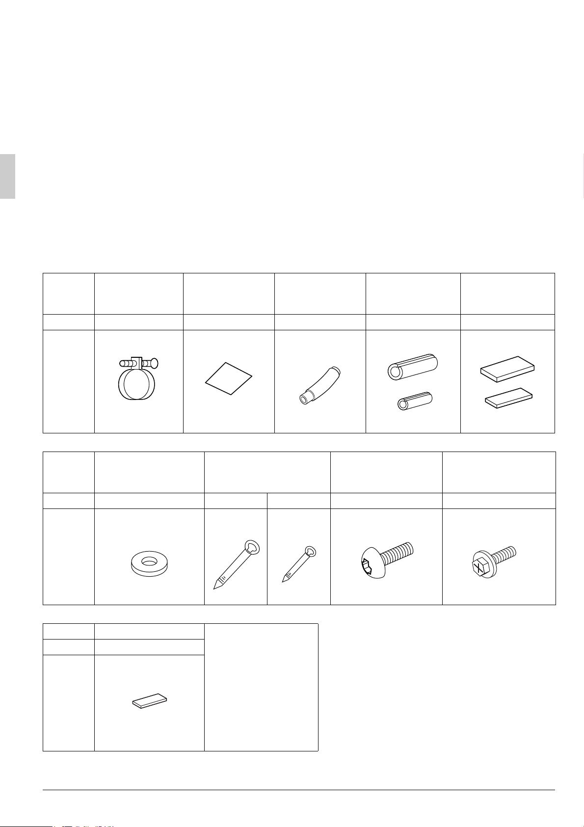
2. Accessories
Check if the following accessories are included with your unit.
(2) Paper pat-
Name (1) Metal clamp
Quantity 1 pc. 1 pc. 1 pc. 1 each 1 each
Shape
Name
Quantity 8 pcs. 6 pcs. 3 pcs. 6 pcs. 12 pcs.
Shape
(8) Washer for
hanger bracket
tern for
installation
(9) Large
Clamp
(10) Small
(3) Drain hose
(11) Screws for fixing
Insulation for
fitting
(4) For gas pipe
(5) For liquid pipe
the paper pattern
for installation
Sealing pad
(6) Large
(7) Middle
(12) Duct companion
flange connection screw
Name
Quantity 2 pcs.
Shape
• Screws for fixing panels are attached to decoration panel.
3 English
(13) Small sealing pad
(Other)
• Operation manual
• Installation manual
Page 5
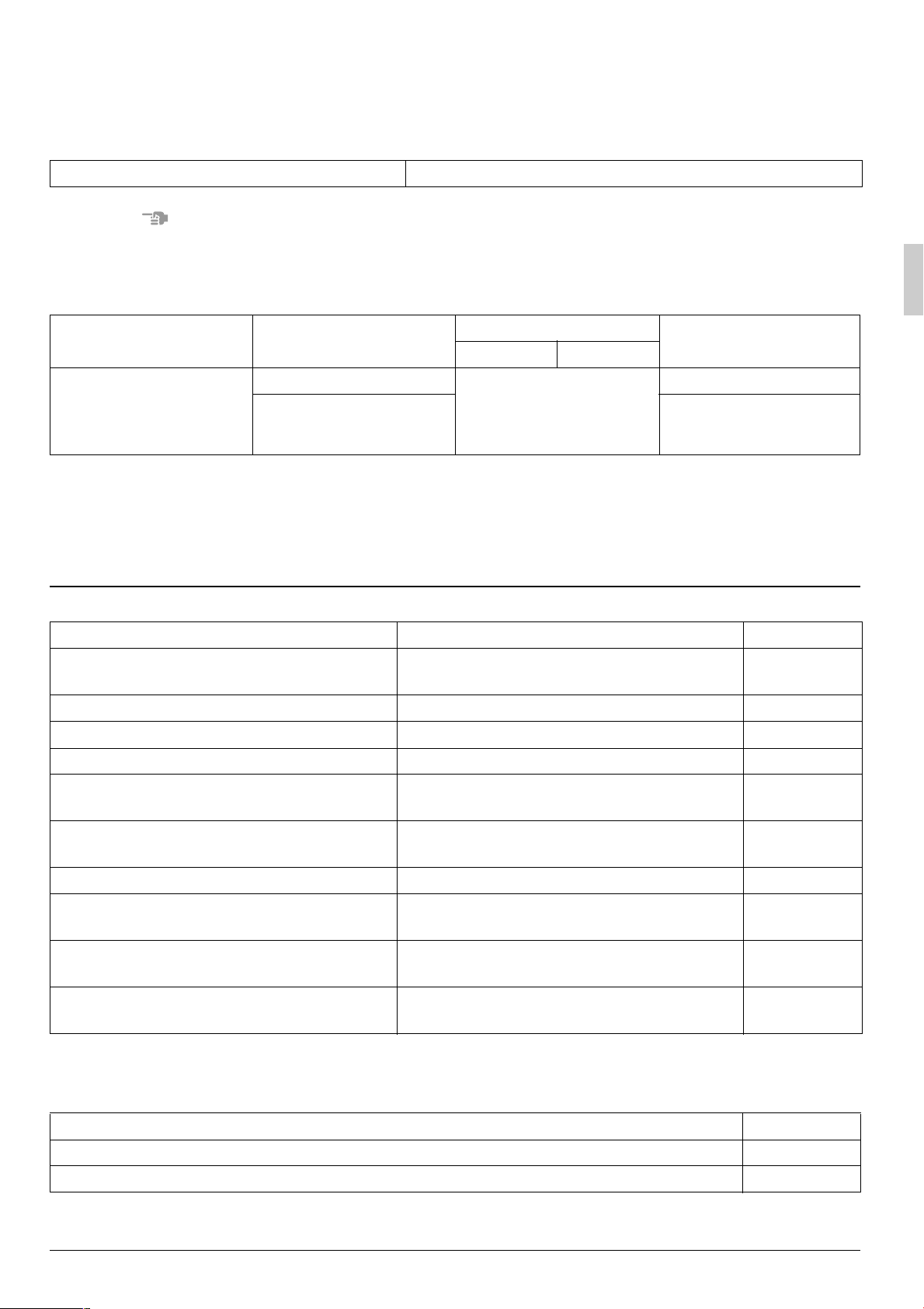
3. Optional accessories
• For this indoor unit, the optional remote controller is necessary. In case of downward air inlet, the dec-
oration panel and the canvas for decoration panel are necessary.
(Refer to “4. PREPARATIONS BEFORE INSTALLATION”)
• Remote controller
Remote controller BRC1C61
NOTE
• If the customer wishes to use a remote controller that is not listed on the table, select a suitable remote
controller after consulting catalogs and technical materials.
• Use the decoration panel which apply to the below table.
Model Min. height above ceiling
FBQ60BV1
FBQ71BV1
FBQ60BVL
FBQ71BVL
∗ When using the canvas duct for the decoration panel, the decoration panel needs at least 42.5 cm
of ceiling space.
FOR THE FOLLOWING ITEMS, TAKE SPECIAL CARE DURING CONSTRUCTION AND CHECK AFTER
INSTALLATION IS FINISHED.
a. Items to be checked after completion of work
Items to be checked If not properly done, what is likely to occur Check
Are the indoor unit and outdoor unit fixed
firmly?
Is the gas leak test finished? It may result in insufficient cooling.
Is the unit fully insulated? Condensate water may drip.
Does drainage flow smoothly? Condensate water may drip.
35 cm or more Installation not required ∗
∗
The unit may drop, vibrate or make noise.
Decoration panel
Color White
BYBS71DJW1
Canvas duct for
decoration panel
KSAJ25K80
Does the power supply voltage correspond
to that shown on the name plate?
Are wiring and piping correct?
Is the unit safely grounded? It may result in electric shock.
Is wiring size according to specifications?
Is something blocking the air outlet or inlet
of either the indoor or outdoor units?
Are refrigerant piping length and additional
refrigerant charge noted down?
b. Items to be checked at time of delivery
∗Also review the “1. SAFETY CONSIDERATIONS”
Items to be checked Check
Did you explain about operations while showing the operation manual to your customer?
Did you hand the operation manual over to your customer?
The unit may malfunction or the components burn out.
The unit may malfunction or the components burn out.
The unit may malfunction or the components burn out.
It may result in insufficient cooling.
The refrigerant charge in the system is not
clear.
English 4
Page 6
c. Points for explanation about operations
The items with WARNING and CAUTION marks in the operation manual are the items pertaining
to possibilities for bodily injury and material damage in addition to the general usage of the product.
Accordingly, it is necessary that you make a full explanation about the described contents and also ask
your customers to read the operation manual.
4. Note to the installer
Be sure to instruct customers how to properly operate the unit (especially cleaning filters, operating different functions, and adjusting the temperature) by having them carry out operations themselves while
looking at the manual.
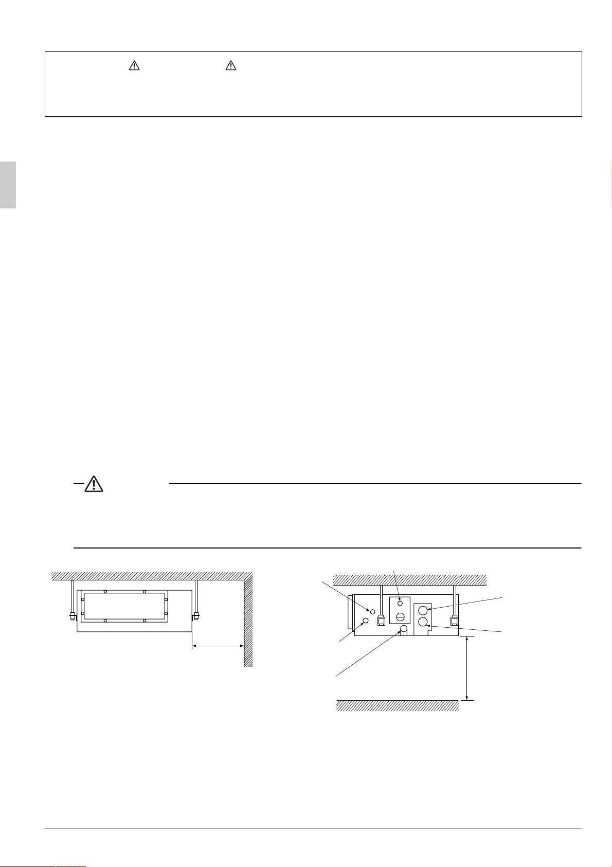
3. SELECTING INSTALLATION SITE
Please attach additional thermal insulation material to the unit body when it is believed that the relative humidity in the ceiling exceeds 80%. Use glass wool, polyethylene foam, or similar with a thickness of 10 mm or
more as thermal insulation material.
1. Select an installation site where the following conditions are fulfilled and that meets
your customer’s approval.
• In the upper space (including the back of the ceiling) of the indoor unit where there is no possible
dripping of water from the refrigerant pipe, drain pipe, water pipe, etc.
• Where optimum air distribution can be ensured.
• Where nothing blocks air passage.
• Where condensate can be properly drained.
• Where the ceiling is strong enough to bear the indoor unit weight.
• Where the false ceiling is not noticeably on an incline.
• Where sufficient clearance for maintenance and service can be ensured.
• Where there is no risk of flammable gas leakage.
• Where piping between indoor and outdoor units is possible within the allowable limit. (Refer to the
installation manual for the outdoor unit.)
CAUTION
•
Keep indoor unit, outdoor unit, power supply wiring and transmission wiring at least 1 meter away from
televisions and radios. This is to prevent image interference and noise in those electrical appliances.
(Noise may be generated depending on the conditions under which the electric wave is generated,
even if 1 meter is kept.)
Drain pipe
Liquid pipe
Power supply
wiring port
Transmission
300 or
more
(Service space)
Gas pipe
Maintenance
drain hose
Floor
Required service space
2500 or higher
from the floor
For installation
in high places
wiring port
2. Use suspension bolts for installation. Check whether the ceiling is strong enough to
support the weight of the unit or not. If there is a risk, reinforce the ceiling before
installing the unit.
(Installation pitch is marked on the paper pattern for installation. Refer to it to check for points requiring
reinforcement.)
5 English
Page 7
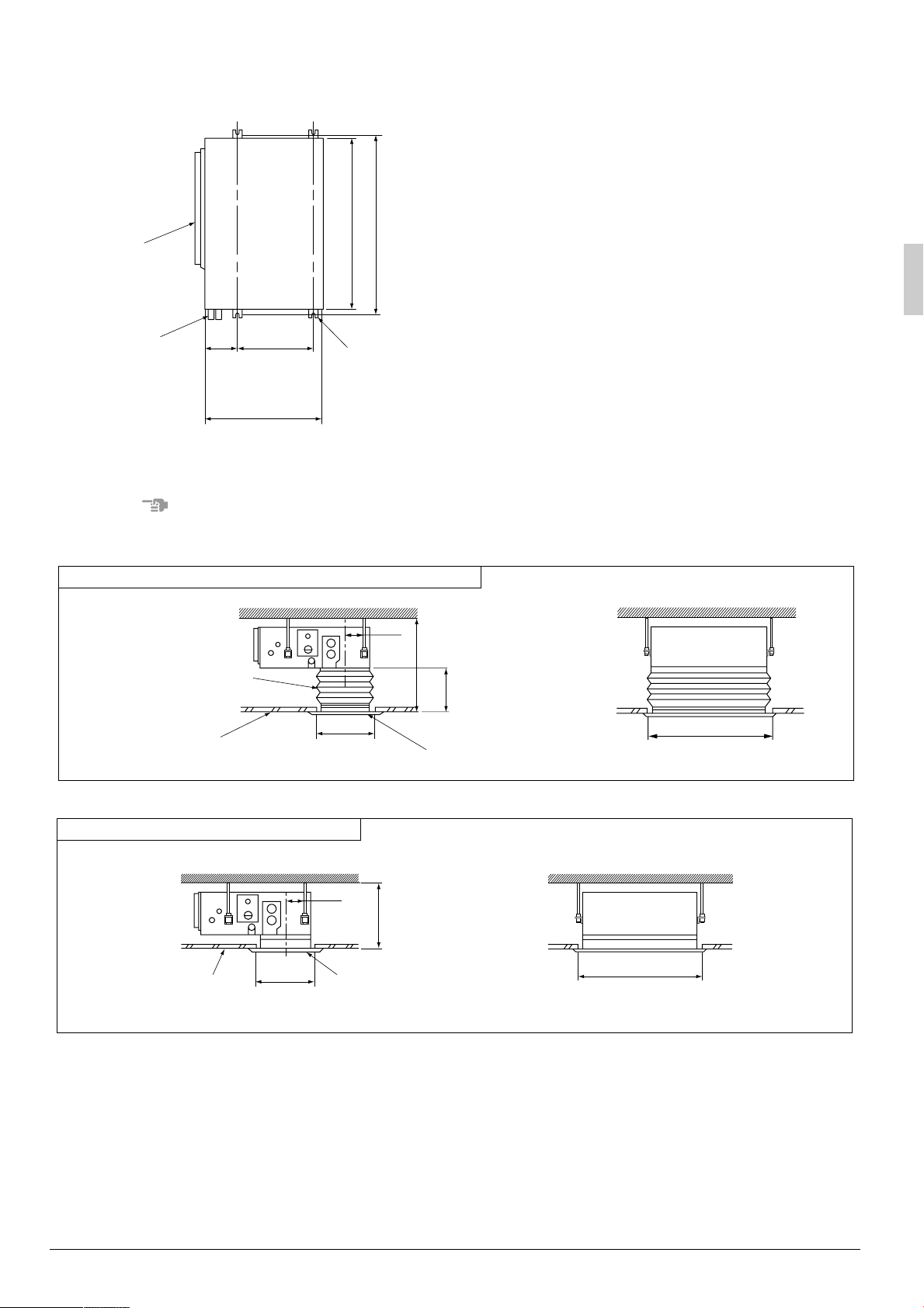
4. PREPARATIONS BEFORE INSTALLATION
1. Relation of ceiling opening to unit and suspension bolt position. (Refer to Fig. 1)
(Indoor unit)
Indoor unit
1050
1000
(Suspension bolt pitch)
Pipe
800 (Indoor unit)
For standard installation (air inlet on the both side), choose one of the below two means of installation.
NOTE
• For other than standard installation, contact your Daikin dealer for details.
For mounting decoration panel with canvas duct
Canvas duct for
decoration panel
(Optional accessory)
Ceiling
surface
630145
(Suspension
bolt pitch)
Fig. 1
(Ceiling opening)
Suspension bolt (×4)
180
or more
425
120
462
Decoration panel
(Optional accessory)
(120-300)
Indoor unit
(Back side)
1060
(Ceiling opening)
For mounting decoration panel directly
Ceiling
surface
180
462
(Ceiling opening)
350
or more
Decoration panel
Indoor unit
(Back side)
1060
(Ceiling opening)
2. The fan speed for this indoor unit is preset to provide standard external static pressure.
• If higher or lower external static pressure is required, reset the external static pressure by changing
the initial setting from the remote controller. Refer to the section entitled “10. FIELD SETTING”.
English 6
Page 8
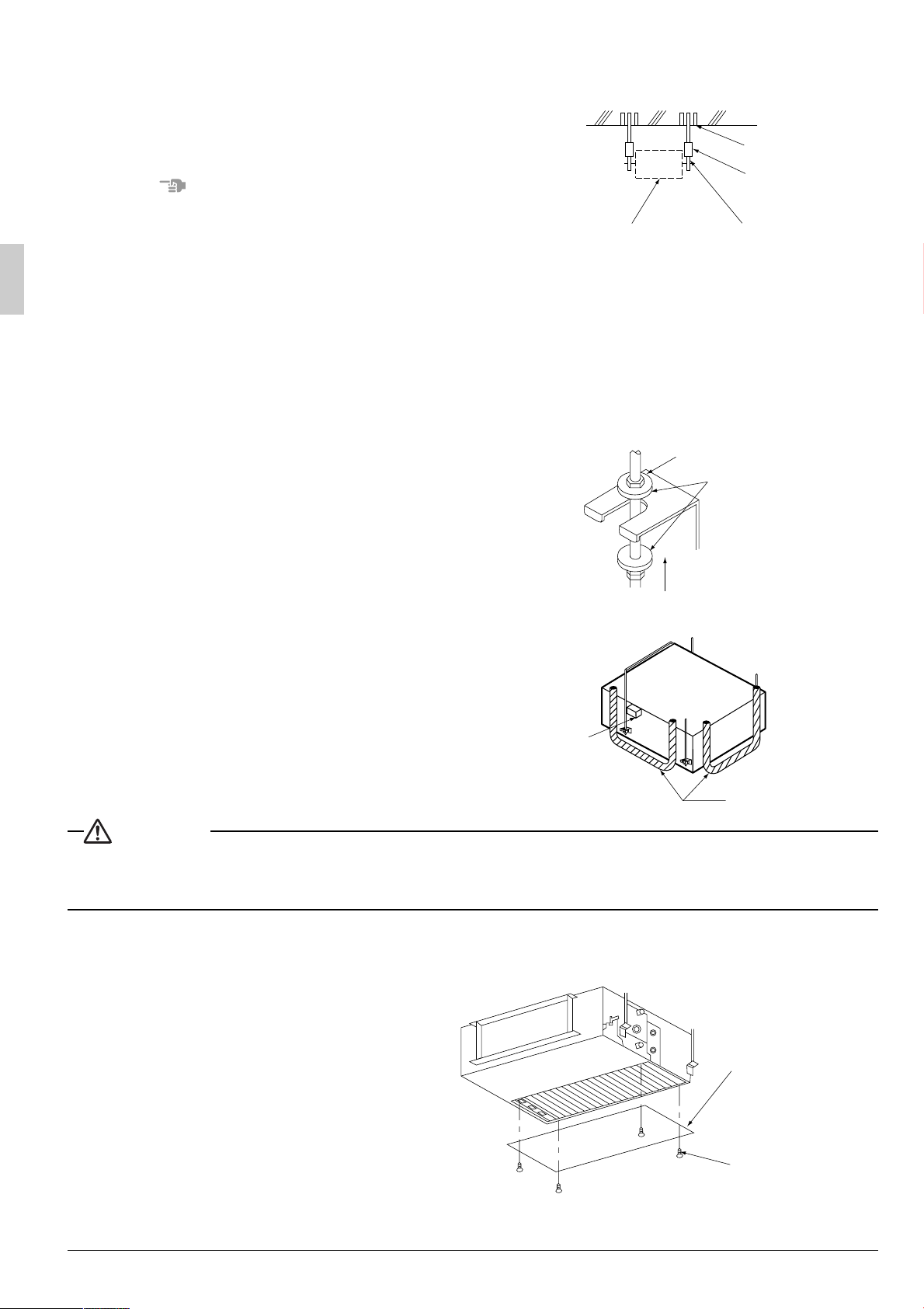
3. Install the suspension bolts. (Refer to Fig. 2)
(Use M10 size bolt for the suspension bolt)
Use anchors for existing ceilings, and a sunken insert,
sunken anchor or other field supplied parts for new ceilings to reinforce the ceiling to bear the weight of the unit.
<Installation example>
Ceiling slab
Anchor
NOTE
• All the above parts are field supplied.
Indoor unit
Fig. 2
Long nut or
turn-buckle
Suspension bolt
5. INDOOR UNIT INSTALLATION
<When installing optional accessories (
manual for optional accessories.
Depending on the field conditions, it may be easier to install optional accessories before the indoor
unit is installed.>
Be sure to use the furnished accessories or ones that match the specifications when installing.
except for the decoration panel
1. Install the indoor unit temporarily.
• Attach the hanger bracket to the suspension bolt. Be sure to
fix it securely by using a nut and washer (8) from the upper
and lower sides of the hanger bracket. (Refer to Fig. 3)
2. Check the unit is horizontally level. (Refer to Fig. 4)
), read also the installation
Field supply
(8)Washer for hanger
bracket (attached)
Tighten (double nuts)
Fig. 3
Level
Fig. 4
CAUTION
• The indoor unit is equipped with a built-in drain pump and float switch. Verify that it is level by using a level
or a water-filled vinyl tube.
(If the unit is tilted against condensate flow, the float switch may malfunction and cause water to drip.)
Vinyl tube
3. Tighten the upper nut.
4. Fix the installation paper pattern
• The paper pattern for installation corre-
sponds with the measurements of the ceiling opening. Consult the builder for details.
• Attach the paper pattern for installation to
the unit with the attached screws.
(Refer to Fig. 5)
The paper pattern for installation is marked
for 3 types of ceiling openings. Read the
notations carefully when installing.
Fig. 5
(2) Paper pattern
for installation
(attached)
(11) Screws for fixing
the paper pattern
for installation
(×6 attached)
7 English
Page 9
6. REFRIGERANT PIPING WORK
For refrigerant piping of outdoor unit and BP unit, see the installation manuals attached to the out-
〈〈〈〈
door unit and BP unit.
〈Execute heat insulation work completely on both sides of the gas piping and the liquid piping. Otherwise, a
water leakage can result sometimes.〉
(When using a heat pump, the temperature of the gas piping can reach up to approximately 120°C, so use
insulation which is sufficiently resistant.)
〈Also, in cases where the temperature and humidity of the refrigerant piping sections might exceed 30°C or
RH80%, reinforce the refrigerant insulation. (20 mm or thicker) Condensate may form on the surface of the
insulating material.〉
〈Be sure to check the type of refrigerant to be used before doing any work. (Using an incorrect refrigerant will
prevent normal operation of the unit.)〉
CAUTION
• Use a pipe cutter and flare suitable for the type of refrigerant.
• Apply ester oil or ether oil around the flare section before connecting.
• To prevent dust, moisture or other foreign matter from infiltrating the tube, either pinch the end or cover it
with tape.
• Do not allow anything other than the designated refrigerant to get mixed into the refrigerant circuit, such as
air, etc. If any refrigerant gas leaks while working on the unit, ventilate the room thoroughly right away.
〉
〉
〉 〉
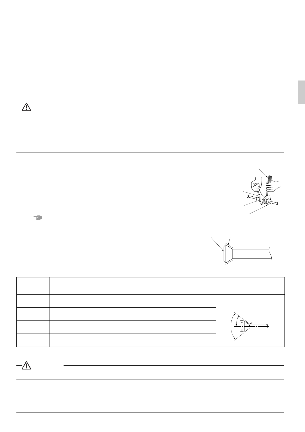
• Be sure to use both a spanner and torque wrench together, as shown
in the drawing, when connecting or disconnecting pipes to/from the
unit. (Refer to Fig. 6)
• Refer to “Table 1” for the dimensions of flare nut spaces.
• When connecting the flare nut, apply ester oil or ether oil to the flare
section (both inside and outside), and spin 3-4 times before screwing
in. (Refer to Fig. 7)
NOTE
• Use the flare nut included with the unit main body.
Table 1
Pipe size Tightening torque
Flare dimensions
A (mm)
φ 6.4 14.2 – 17.2N·m (144 – 176 kgf·cm) 8.7 – 9.1
φ 9.5 32.7 – 39.9N·m (333 – 407 kgf·cm) 12.8 – 13.2
φ 12.7 49.5 – 60.3N·m (504 – 616 kgf·cm) 16.2 – 16.6
Torque wrench
Spanner
Pipe union
Flare nut
Fig. 6
Coat here with ester or ether oil
Fig. 7
Flare
0
2
±
0
45
0
0.5
±
0
90
R0.4-0.8
A
φ 15.9 61.8 – 75.4N·m (630 – 770 kgf·cm) 19.3 – 19.7
• Refer to “Table 1” to determine the proper tightening torque.
CAUTION
Over-tightening the flare nut may break it and/or cause the refrigerant to leak.
English 8
Page 10
Not recommendable but in case of emergency
You must use a torque wrench but if you are obliged to install the unit without a torque wrench, you may
follow the installation method mentioned below
After the work is finished, make sure to check that there is no gas leak.
When you keep on tightening the flare nut with a spanner, there is a point where the
tightening torque suddenly increases. From that position, further tighten the flare nut the angle shown
below:
Pipe size Further tightening angle Recommended arm length of tool
φ 6.4 (1/4”) 60 to 90 degrees Approx. 150mm
φ 9.5 (3/8”) 60 to 90 degrees Approx. 200mm
φ 12.7 (1/2”) 30 to 60 degrees Approx. 250mm
φ 15.9 (5/8”) 30 to 60 degrees Approx. 300mm
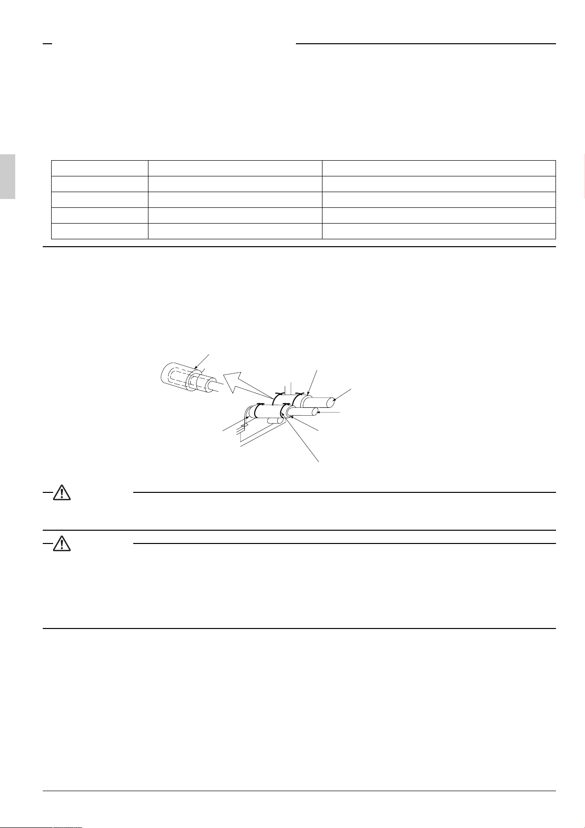
• Make absolutely sure to execute heat insulation works on the pipe-connecting section after checking gas
leakage by thoroughly studying the following figure and using the attached heat insulating materials for
fitting (4) and (5). (Fasten both ends with the clamps (9).) (Refer to Fig. 8)
• Wrap the sealing pad (7) only around the insulation for the joints on the gas piping side. (Refer to Fig. 8)
(7) Middle sealing pad (attached)
(Wrap from the bottom up)
(4) Insulation for fitting (attached)
(for gas line)
Gas pipe
Liquid pipe
Attach to the bottom
(For both gas piping
and liquid piping)
(5)Insulation for fitting (attached)
(for liquid line)
(9) Clamp (attached) (×4)
Fig. 8
CAUTION
For local insulation, be sure to insulate local piping all the way into the pipe connections inside the machine.
Exposed piping may cause condensation or burns on contact.
CAUTION
CAUTION TO BE TAKEN WHEN BRAZING REFRIGERANT PIPING
“Do not use flux when brazing refrigerant piping. Therefore, use the phosphor copper brazing filler metal
(BCuP-2: JIS Z 3264/B-Cu93P-710/795: ISO 3677) which does not require flux.”
(Flux has extremely harmful influence on refrigerant piping systems. For instance, if the chlorine based
flux is used, it will cause pipe corrosion or, in particular, if the flux contains fluorine, it will damage the refrigerant oil.)
• Before brazing local refrigerant piping, nitrogen gas shall be blown through the piping to expel air from the
piping.
If you brazing is done without nitrogen gas blowing, a large amount of oxide film develops inside the piping,
and could cause system malfunction.
• When brazing the refrigerant piping, only begin brazing after having carried out nitrogen substitution or
while inserting nitrogen into the refrigerant piping. Once this is done, connect the indoor unit with a flared
or a flanged connection.
9 English
Page 11
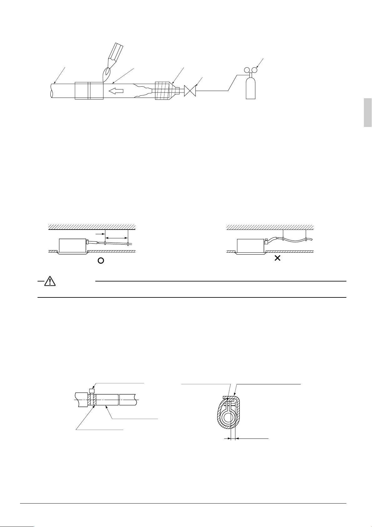
• Nitrogen should be set to 0.02 Mpa (0.2 kg/cm
nitrogen into the piping. (Refer to Fig. 9)
Refrigerant piping
Part to be
brazed
2
) with a pressure-reducing valve if brazing while inserting
Pressure-reducing valve
Taping
hands valve
Nitrogen
Nitrogen Fig. 9
7. DRAIN PIPING WORK
1. Rig drain piping (Refer to Fig. 10, Fig. 11)
• As for drain work, perform piping in such a manner that water can be drained properly.
As for drain piping, the connection can be made from three different directions.
• Employ a pipe with either the same diameter or with the diameter larger (excluding the raising section)
than that of the connecting pipe (PVC pipe, nominal diameter 25 mm, outside diameter 32 mm).
• Keep the drain pipe short and sloping downwards at a gradient of at least 1/100 to prevent air pockets
from forming.
• If the drain pipe cannot be sufficiently set on a slope, execute the drain raising piping.
• To keep the drain pipe from sagging, space hanging wires every 1 to 1.5 m.
Hanger bracket
1~1.5 m
Fig. 10
1/100 gradient or more
Fig. 11
CAUTION
Water pooling in the drainage piping can cause the drain to clog.
• Use the attached drain hose (3) and Metal clamp (1).
• Insert the drain hose into the drain socket up to the base, and tighten the Metal clamp securely within
the portion of a white tape of the hose-inserted tip. Tighten the Metal clamp until the screw head is less
than 4 mm from the hose.
• Wrap the attached sealing pad (6) over the Metal clamp and drain hose to insulate.
• Make sure that heat insulation work is executed on the following 2 spots to prevent any possible water
leakage due to dew condensation.
• Indoor drain pipe
• Drain socket
Metal clamp (1)
Metal clamp (1)
(attached)
Large sealing pad (6)
(attached)
Drain hose (3)
Tape (White)
4 mm
≥
Fig. 12
Fig. 13
English 10
Page 12
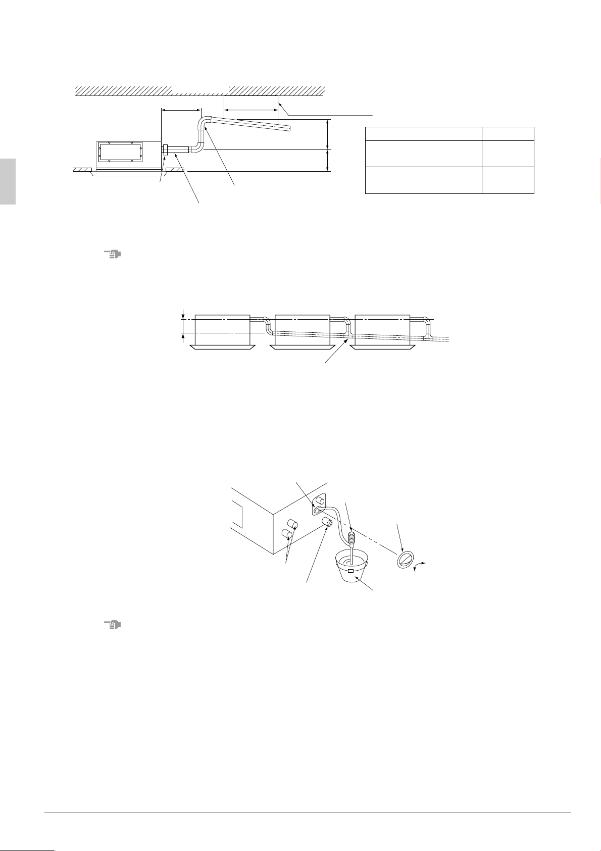
<PRECAUTIONS FOR DRAIN RAISING PIPING>
• Install the drain raising pipes at a height of less than 250 mm.
• Install the drain raising pipes at a right angle to the indoor unit and no more than 300 mm from the unit.
Ceiling slab
300 mm or less
1~1.5m
Hanging bracket
Adjustable (0~250mm)
A
(1) Metal clamp
(attached)
NOTE
• To ensure no excessive pressure is applied to the included drain hose (3), do not bend or twist when
installing. (This may cause leakage.)
• If converging multiple drain pipes, install according to the procedure shown below.
Select converging drain pipes whose gauge is suitable for the operating capacity of the unit.
(3) Drain hose(attached)
Fig. 14
100 mm
≥
Drain raising pipe
(Field supplied parts)
T-joint converging drain pipes
Fig. 15
When canvas duct
is installed
When decoration panel
is directly installed
A
350 - 530
275
2. After piping work is finished, check if drainage flows smoothly.
• Open the water inlet lid, add approximately 1000 cc of water gradually and check drainage flow.
(Refer to Fig. 16)
Water inlet
Portable pump
Water inlet lid
Refrigerant pipes
Drain outlet for maintenance
(with rubber plug)
Fig. 16
NOTE
• Use the drain outlet for maintenance to drain water from the drain pan.
WHEN ELECTRIC WIRING WORK IS FINISHED
• Check drainage flow during cool running, explained in the section entitled. “12. TEST OPERATION”
Bucket
Close
Open
11 English
Page 13
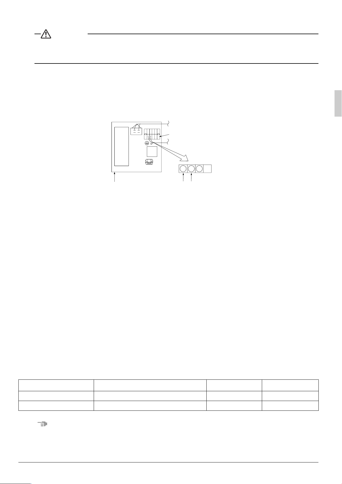
WHEN ELECTRIC WIRING WORK IS NOT FINISHED
CAUTION
• Electrical wiring work should be done by a certified electrician.
• If someone who does not have the proper qualifications performs the work, perform the following after
test run is complete.
• Remove the control box lid. Connect the single phase power supply (SINGLE PHASE 50/60Hz
220-240V/220V) to connections No.1 and No.2 on the terminal block for wiring the units. Do not connect to No.3 of the terminal block for wiring the units. (The drain pump will not operate.) Connect the
ground wire firmly. When carrying out wiring work around the control box, make sure none of the connectors come undone. Be sure to attach the control box before turning on the power.
• After confirming drainage (Fig. 16, Fig. 17), turn off the power and remove the power supply.
• Attach the control box lid as before.
Terminal block for wiring
1 2 3
Control box
Single phase power supply
Fig. 17
8. ELECTRIC WIRING WORK
• All field supplied parts and materials and electric works must conform to local codes.
• Use copper wire only.
• For electric wiring work, refer also to “13. WIRING DIAGRAM”
• For remote controller wiring details, refer to the installation manual attached to the remote controller.
• All wiring must be performed by an authorized electrician.
• A circuit breaker capable of shutting down power supply to the entire system must be installed.
• Refer to the installation manual attached to the outdoor unit and BP unit for the size of power supply electric
wire connected to the outdoor unit, the capacity of the circuit breaker and switch, and wiring instructions.
• Be sure to ground the air conditioner
• Do not connect the ground wire to gas pipes, plumbing pipes, lightning rods, or telephone ground wires.
• Gas pipes: might cause explosions or fire if gas leaks.
• Plumbing: no grounding effect if hard vinyl piping is used.
• Telephone ground wires or lightning rods: might cause abnormally high electric potential in the ground
during lighting storms.
• Specifications for field wire
The remote controller cord should be procured locally. Refer to the Table 2 when preparing one.
Table 2
Wire
Size (mm
Wiring the units H05VV - U4G (NOTE 1) 2.5
Remote controller cord
(NOTE 2) (2 wires)
0.75 - 1.25 Max. 500 m
2
)
Length
-
NOTE
1. Shows only in case of protected pipes. Use H07RN-F in case of no protection.
2. For Asian market : Vinyl cord with sheath or cable (Insulated thickness : 1mm or more)
For Australian regular : Shield wire (Insulated thickness : 1mm or more)
English 12
Page 14
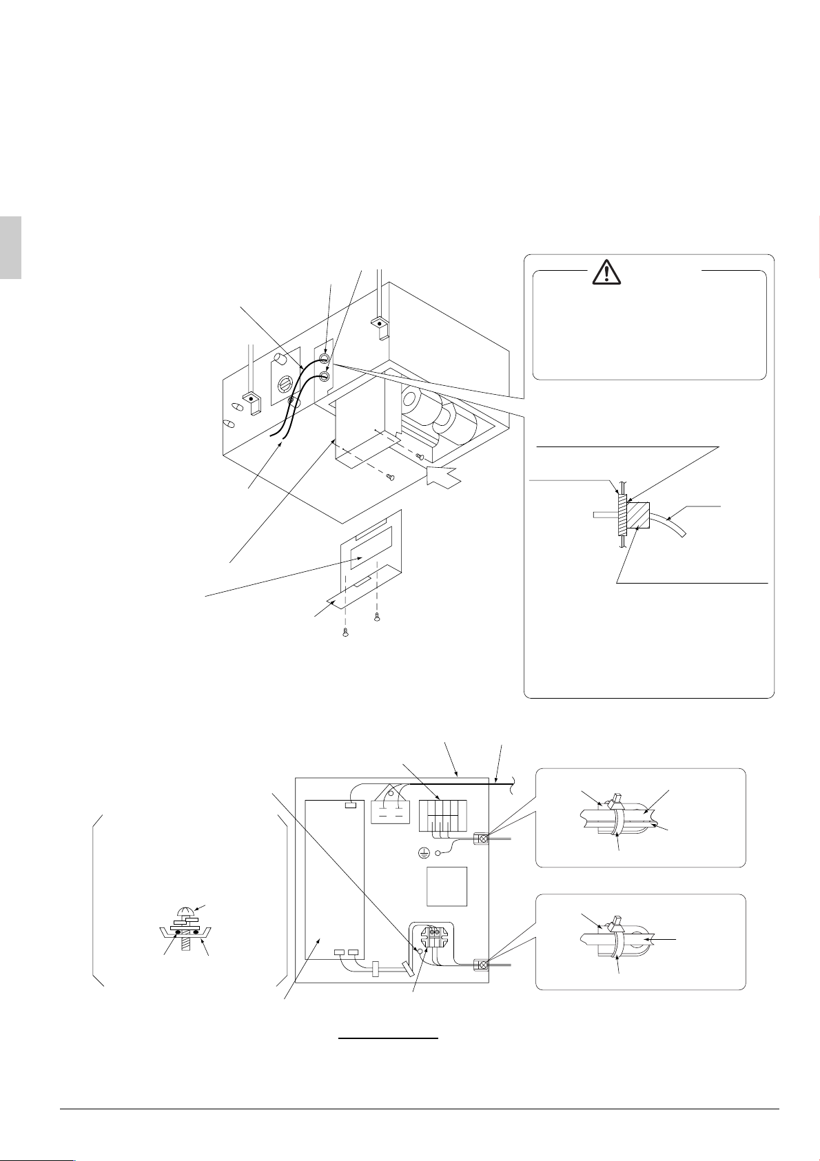
PRECAUTION
Connection of wiring units, ground wire and remote controller cord. (Refer to Fig. 18 and 19)
• Wiring the units and ground for the wire
Remove the control box lid and pull out the control box. (Refer to Fig. 18)
Next, pull the wires inside through the rubber bush A and connect them to their respective terminals on the
terminal block for wiring the units (4P) inside. Also, connect the ground wire to the ground terminal. In doing
this, pull the wiring through the rubber bush A and fix it in place with the clamp.
• Remote controller cord
Connect the cord to the terminal block for remote controller (2P) (no polarity). In doing this, pull the wiring
through the rubber bush B and fix it in place with the clamp.
Rubber bush A
*Wiring the units
Do not clamp remote
*
controller cords together with
wires connecting the units.
Doing so may cause
malfunction.
*Remote controller cord
Control box
WIRING DIAGRAM
Control box lid
Rubber bush B
Fig. 18
A
CAUTION
•
After wiring, adhere the attached
small sealing pad (13) around the
wires as shown below.
(Be sure to adhere it to avoid
water from outside unit.)
Note) No gap are allowed.
(Between rubber bush
and sealing material.)
Rubber bush
Wire
Inside unit Outside unit
Small sealing pad (13)
(Adhere it around the wire)
[ How to adhere it ]
Note) In case of two wires or more,
adhere sealing material to
each wire separately.
Control box
Motor lead wire
Terminal block for
wiring the units
Grounding terminal for
the remote controller
Ground the shield
part of shield wire.
If using shield wire.
Clamp material
123
(10) Clamp (attached)
Wiring the
units
Ground
wire
Refer to NOTE of
“9. WIRING EXAMPLE”
Shield part
Grounding
terminal
C-cup
washer
Indoor PC board
P1P2
Terminal block for remote controller
Clamp material
Remote
controller
cord
(10) Clamp (attached)
Arrow view A
Fig. 19
13 English
Page 15
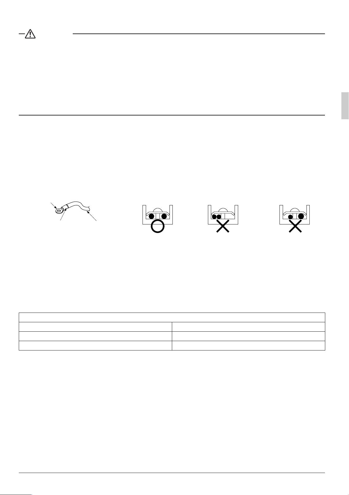
Observe the notes mentioned below when wiring to the terminal block for wiring the units.
CAUTION
• When clamping wiring, use the included clamping material to prevent outside pressure being exerted on
the wiring connections and clamp firmly. When doing the wiring, make sure the wiring is neat and does not
cause the control box lid to stick up, then close the cover firmly.
• When attaching the control box lid, make sure you do not pinch any wires.
• After all the wiring connections are done, fill in any gaps in the through holes with putty or insulation (pro-
cured locally) to prevent small animals and insects from entering the unit from outside. (If any do get in, they
could cause short circuits in the control box.)
• Outside the machine, separate the weak wiring (remote controller cord) and strong wiring (interunit,
ground, and other power wiring) at least 50 mm so that they do not pass through the same place together.
Proximity may cause electrical interference, malfunctions, and breakage.
• Do not connect wires of different gauge to the same power supply terminal. (Looseness in the connection
may cause overheating.) (Refer to Fig. 20)
• Observe the notes when wiring to the terminal block for wiring the units.
(Use a round crimp-style terminal with insulation sleeve for connection to the terminal block for wiring the
units. In case it cannot be used due to unavoidable reasons, connect wires of the same gauge to the both
side as shown in Fig. 20.)
Round crimp-style
terminal
Attach insulation
Connect wires of the
same gauge to both
side. (GOOD)
Electric wire
Do not connect wires
of the same gauge to
one side.(WRONG)
Do not connect
wires of different
gauges.(WRONG)
sleeve
Fig. 20
Follow the instructions below if the wiring gets very hot due to slack in the power wiring.
• In wiring, make certain that prescribed wires are used, carry out complete connections, and fix the wires so
that outside forces are not applied to the terminals.
• Use the correct screwdriver for tightening the terminal screws. If the blade of screwdriver is too small, the
head of the screw might be damaged, and the screw will not be properly tightened.
• If the terminal screw are tightened too hard, screws might be damaged.
• Refer to the table below for the tightening torque of the terminal screws.
Tightening torque (N·m)
Terminal block for remote controller 0.79 to 0.97
Terminal block for wiring the units 1.18 to 1.44
Ground terminal 1.44 to 1.94
English 14
Page 16
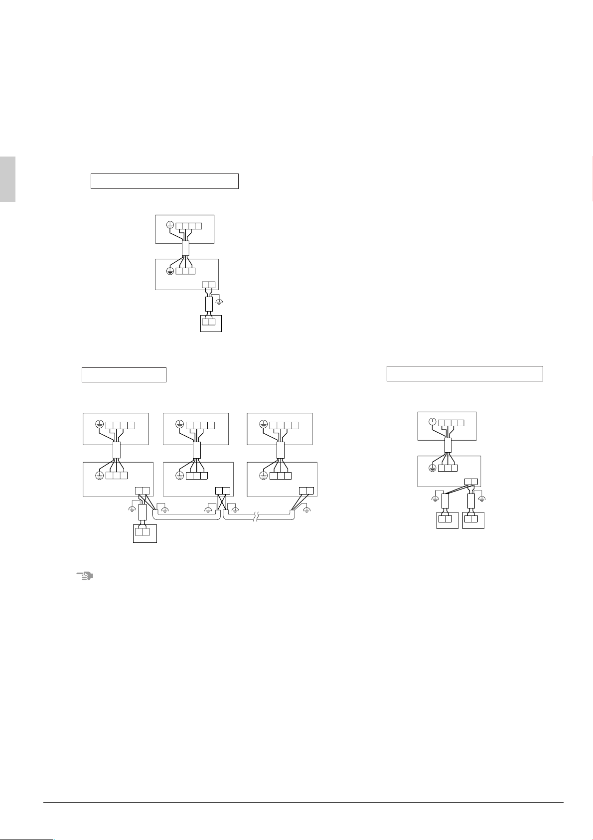
9. WIRING EXAMPLE
For the wiring of outdoor unit and BP unit, refer to the installation manuals attached to the outdoor unit and
BP unit.
Confirm the system type.
1 remote controller control: 1 remote controller controls 1 indoor unit (standard system). (Refer to Fig. 21)
•
• Group control: 1 remote controller controls up to 16 indoor units.
(All indoor units operate according to the remote controller.) (Refer to Fig. 22)
• 2 remote controllers control: 2 remote controllers control 1 indoor unit. (Refer to Fig. 23)
Fig. 21
1 remote controller control
BP unit
3
1
2
Indoor unit
3
1
2
P
1P2
(NOTE.2)
Remote controller
(Optional accessories)
.
P1P2
Fig. 22
Group control
BP unit BP unit BP unit
3
1
2
3
1
2
Indoor unit Indoor unit Indoor unit
1
2
(NOTE.2)
3
P
1P2
(NOTE.2) (NOTE.2)
P1P
2
3
1
2
P
1P2
(NOTE.2)
Remote controller
1
2
1
2
3
3
P
1P2
(NOTE.2)
Fig. 23
2 remote controllers control
BP unit
3
1
2
Indoor unit
3
1
2
1P2
P
(NOTE.2) (NOTE.2)
P1P2P1P2
Remote controller
(Optional accessories)
(Optional accessories)
NOTE
1. All transmission wiring except for the remote controller wires is polarized and must match the terminal
symbol.
2.
In case a shielding wire is to be used, connect a shielded portion with the grounding terminal for remote
controller inside the control box. (Also, connect the ground for the remote control to a grounded metal part.)
3. For group control remote controller, choose the remote controller that suits the indoor unit which has the
most functions (as attached swing flap)
15 English
Page 17
10. FIELD SETTING
<Field setting must be made from the remote controller in accordance with the installation condition.>
• Setting can be made by changing the “Mode No.”, “FIRST CODE NO.” and “SECOND CODE NO.”.
• For setting procedures and instructions, refer to the “FIELD SETTING” in the installation manual of the
remote controller.
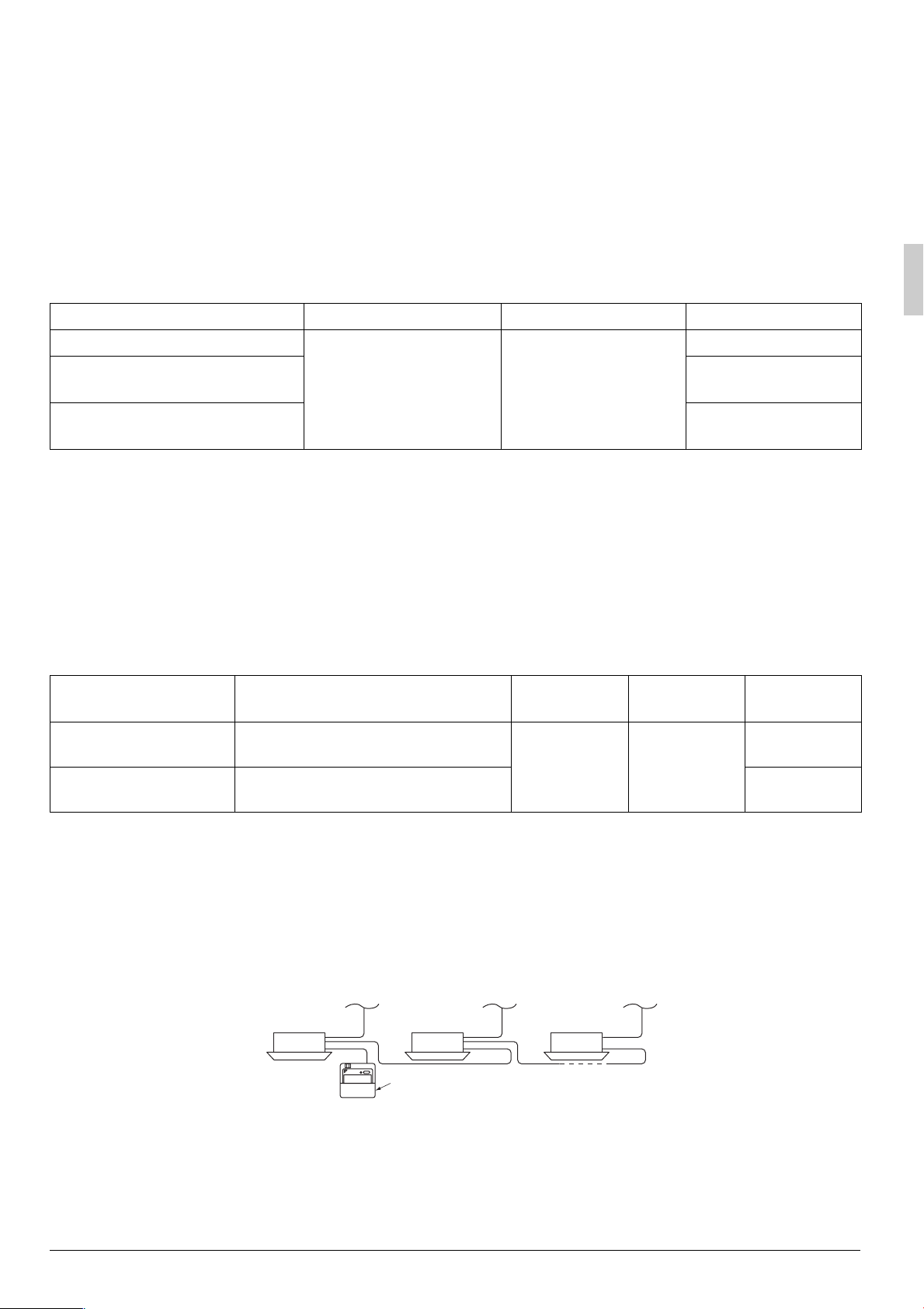
1. Setting external static pressure
•
Change the SECOND CODE No. according to Table 3 depending on the resistance of the connecting duct.
(SECOND CODE NO. is factory set to “01” normal.)
Table 3
External static pressure Mode No. FIRST CODE NO. FIRST CODE NO.
Normal: 49Pa (5 mmH
High static pressure:
88/108Pa (9/11 mmH
Low static pressure: 20Pa
(2 mmH
2
O)
2. Setting with installing optional accessories
• Refer to the installation manual of the optional accessories for the optional accessories installation.
2
2
O)
O)
13 (23) 6
01
02
03
3. Setting air filter sign
•
Remote controllers are equipped with liquid crystal display air fil
er signs to display the time to clean air
filters.
•
Change the SECOND CODE No. according to Table 4 depending on the amount of dirt or dust in the room.
(SECOND CODE NO. is factory set to “01” for filter contamination-light)
Table 4
Setting
Air filter
contamination-light
Air filter
contamination-heavy
Spacing time of display air filter
sign (long life type)
Approx. 2500 hrs
Approx. 1250 hrs 02
Mode No.
10 (20) 0
FIRST CODE
NO.
4. When implementing group control
• When using as a pair unit or as a parent unit for simultaneous operation multi, you may simultaneous
start/stop (group) control up to 16 unit with the remote controller.
• In this case, all the indoor units in the group will operate in accordance with the group control remote
controller.
• Select a remote controller which matches as many of the functions (swing flap, etc) in the group as
possible.
SECOND
CODE NO.
01
Indoor unit 1 Indoor unit 2
Indoor unit 3
Group control remote control
Fig. 24
Wiring Method
(1)Remove the control box lids. (See ‘‘8. ELECTRIC WIRING WORK’’.)
(2)Cross-wire the terminal block for remote controller (P
) inside the control box. (There is no
1 P2
polarity.) (Refer to Fig. 22 on page 15 and Table 2 on page 12)
English 16
Page 18
5. Control by 2 remote controllers
(
Controlling 1 indoor unit by 2 remote controllers
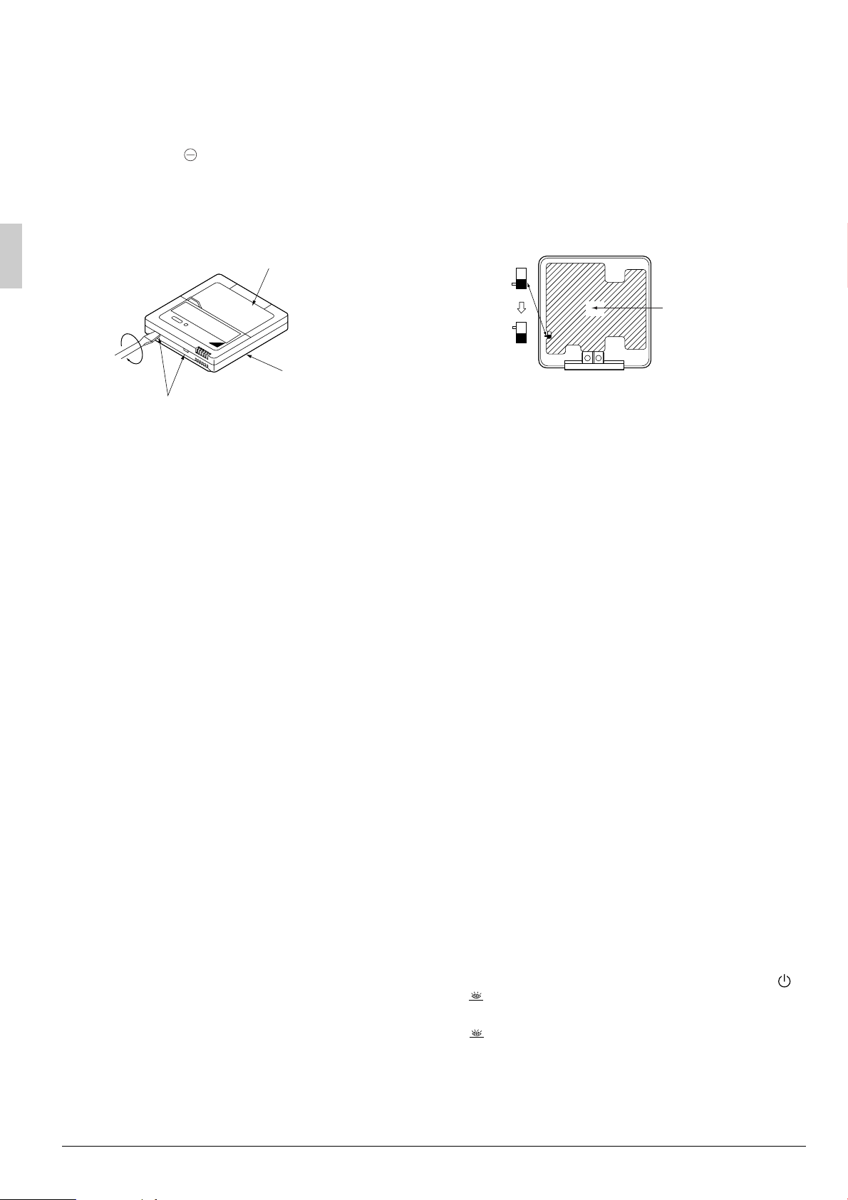
• When using 2 remote controllers, one must be set to “MAIN” and the other to “SUB”.
MAIN/SUB CHANGEOVER
(1)Insert a screwdriver into the recess between the upper and lower part of remote controller and,
working from the 2 positions, pry off the upper part. (The remote controller PC board is attached to
the upper part of remote controller.) (Refer to Fig. 25)
(2)Turn the MAIN/SUB changeover switch on one of the two remote controller PC board to “S”.
(Leave the switch of the other remote controller set to “M”.) (Refer to Fig. 26)
Upper part of remote controller
(Factory setting)
Lower part of
remote
controller
Insert the screwdriver here and gently
work off the upper part of remote controller.
Fig. 25
(Only one remote controller
needs to be changed
if factory settings have
remained untouched.)
)
S
S
M
Remote controller
S
M
Fig. 26
PC board
Wiring Method (See ‘‘8. ELECTRIC WIRING WORK’’ on page 12)
(3)Remove the control box lids.
(4)Add remote control 2 (slave) to the terminal block for remote controller (P
, P2) in the control
1
box. (There is no polarity.) (Refer to Fig. 23 on page 15 and Table 2 on page 12)
11. INSTALLATION OF THE DECORATION PANEL
Refer to the installation manual attached to the decoration panel.
After installing the decoration panel, ensure that there is no space between the unit body and decoration
panel.
12. TEST OPERATION
Refer to the section of “FOR THE FOLLOWING ITEMS, TAKE SPECIAL CARE DURING CONSTRUCTION AND CHECK AFTER INSTALLATION IS FINISHED” .
• After finishing the construction of refrigerant piping, drain piping, and electric wiring, conduct test operation
accordingly to protect the unit.
1. How to test operation
1. Open the gas side stop valve.
2. Open the liquid side stop valve.
3.
Electrify crank case heater for 6 hours (Not required in case of a unit exclusively designed for cooling
only).
4.
Set to cooling operation with the remote controller and start operation by pushing ON/OFF button ( ).
5. Press INSPECTION/TEST OPERATION button ( ) 4 times (2 times for wireless remote control-
ler) and operate at Test Operation mode for 3 minutes.
6. Press INSPECTION/TEST OPERATION button ( ) and operate normally.
7. Confirm function of unit according to the operation manual.
TEST
TEST
17 English
Page 19
PRECAUTIONS
• Refer to the diagnoses below if the unit does not operate properly.
• After completing the test run, press the INSPECTION/TEST OPERATION button once to put the
unit in inspection mode, and make sure the Malfunction code is “00” (=normal).
If the code reads anything other than “00”, refer to the malfunction diagnoses below.
NOTE
• If a malfunction is preventing operation, refer to the malfunction diagnoses below.
2. Cautions for servicing
With the power on. Troubles can be monitored on the remote controller.
• If the air conditioner does not operate normally after installing the air conditioner.
a malfunction shown in the table below may happened.
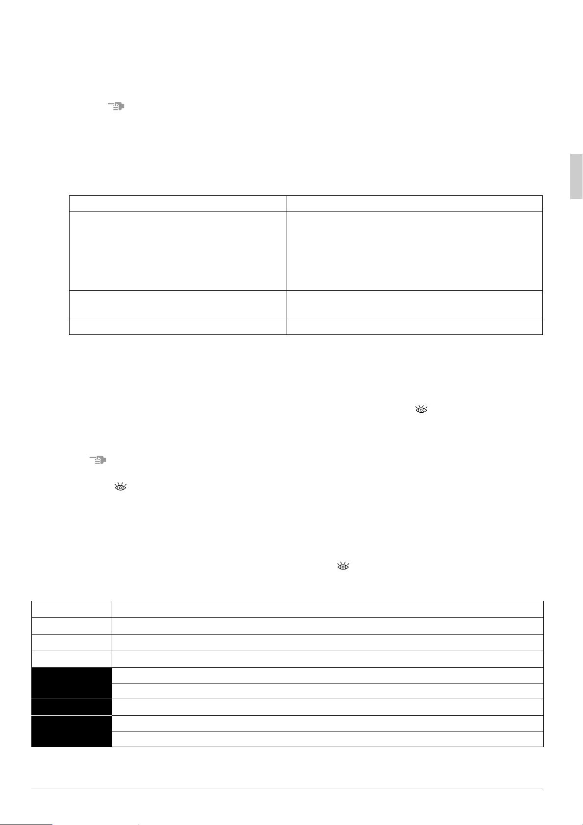
Remote control display Malfunction
• Power supply trouble or Open phase connection
• Wrong wiring between indoor and outdoor unit
No display
88∗
88 flashing • Wrong wiring between indoor and outdoor unit
• Indoor PC board faulty
• Wrong remote control connection wiring
• Remote control faulty
• Fuse faulty
• Indoor PC board faulty
• Wrong wiring between indoor and outdoor unit
∗After turning on the power, the maximum is 90 seconds, although it will only display “88”. This is not
a problem, and it will be set for 90 seconds.
! Trouble shooting with the display on the liquid crystal display remote controller.
With the wired remote controller. (NOTE 1)
When the operation stops due to trouble, operation lamp flashed, and “ ” and the Malfunction
code are indicated on the liquid crystal display. In such a case, diagnose the fault contents by refering to the table on the Malfunction code list it case of group control, the unit No. is displayed so that
the indoor unit no with the trouble can be recognized. (NOTE 2)
NOTE
1. In case wired remote controller. Press the INSPECTION /TEST OPERATION button on remote con-
troller, “ ” starts flashing and changes the inspection mode.
2. Keep down the ON/OFF button for 5 seconds or longer in the inspection mode and the above trouble
history disappears, after the Malfunction code goes on and off twice, followed by the code “00”(normal). The display changes from the inspection mode to the normal mode.
3. Malfunction code
• For places where the Malfunction code is left blank, the “ ” indication is not displayed. Though the
system continues operating, be sure to inspect the system and make repairs as necessary.
• Depending on the type of indoor or outdoor unit, the Malfunction code may or may not be displayed.
Code
A1
A3
A6
A7
AF
AH
Indoor unit’s PC board faulty
Drain water level abnormal
Indoor fan motor overloaded, overcurrent or locked
Swing flap motor locked
Only the air flow direction can not be controlled.
Humidifier faulty
Air cleaner faulty
Only the air cleaner does not function.
Malfunction/Remarks
English 18
Page 20
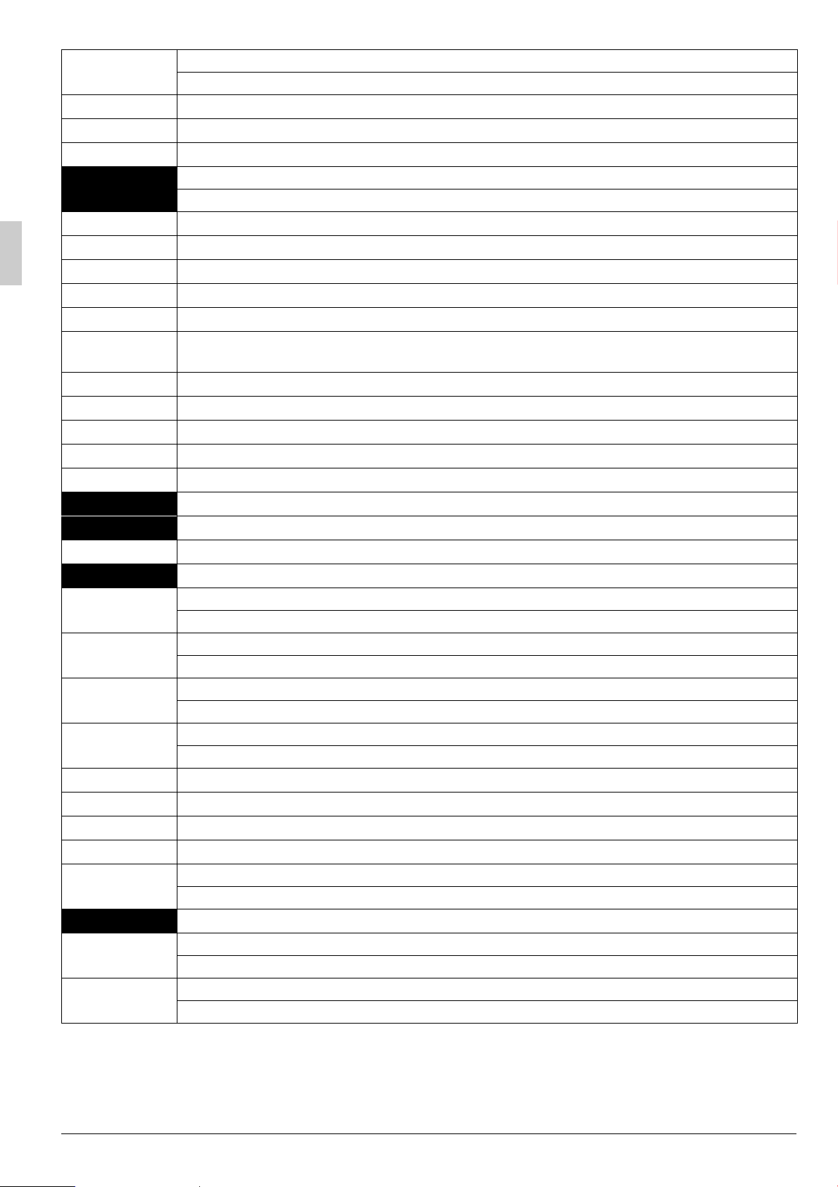
AJ
C4
C5
C9
CJ
E0
E1
E3
E4
E5
E7
E9
F3
H3
H4
H7
H9
J3
J5
J6
L4
L5
L8
L9
LC
P1
P3
P4
PJ
U0
U1
U2
Type set improper
Capacity data is wrongly preset. Or there is nothing programmed in the data hold IC.
Sensor (R2T) for heat exchanger temperature is fault
Sensor (R3T) for heat exchanger temperature is fault
Sensor for suction air temperature is fault
Sensor for remote controller is fault
The remote controller thermistor does not function, but the system thermo run is possible.
Action of safety device (outdoor unit)
Outdoor unit’s PC board faulty (outdoor unit)
High pressure abnormal (outdoor unit)
Low pressure abnormal (outdoor unit)
Compressor motor lock malfunction (outdoor unit)
Outdoor fan motor lock malfunction
Outdoor fan instantaneous overcurrent malfunction (outdoor unit)
Electronic expansion valve faulty (outdoor unit)
Discharge pipe temperature abnormal (outdoor unit)
High pressure switch faulty (outdoor unit)
Low pressure switch faulty (outdoor unit)
Outdoor motor position signal malfunction (outdoor unit)
Outdoor air thermistor faulty (outdoor unit)
Discharge pipe thermistor faulty (outdoor unit)
Suction pipe thermistor faulty (outdoor unit)
Heat exchanger thermistor faulty (outdoor unit)
Overheated heat-radiating fin (outdoor unit)
Inverter cooling defect.
Instantaneous overcurrent (outdoor unit)
Possible earth fault or short circuit in the compressor motor.
Electric thermal (outdoor unit)
Possible electrical overload in the compressor or cut line in the compressor motor.
Stall prevention (outdoor unit)
Compressor possibly locked.
Transmission malfunction between the outdoor control units’ inverters (outdoor unit)
Open-phase (outdoor unit)
PC board temperature sensor malfunction (outdoor unit)
Heat-radiating fin temperature sensor malfunction (outdoor unit)
Type set improper (outdoor unit)
Capacity data is wrongly preset. Or there is nothing programmed in the data hold IC.
Suction pipe temperature abnormal
Reverse phase
Reverse two of the L1,L2 and L3 leads.
Power source voltage malfunction (outdoor unit)
Includes the defect in K1M.
19 English
Page 21
U4
UF
U5
U8
UA
UC
Transmission error (indoor unit – outdoor unit)
Wrong wiring between indoor and outdoor units or malfunction of the PC board mounted
on the indoor and the outdoor units.
If UF is shown, the wiring between the indoor and outdoor units is not properly wired.
Therefore, immediately disconnect the power supply and correct the wiring. (The compressor and the fan mounted on the outdoor unit may start operation independent of the
remote controller operation.)
Transmission error (indoor unit – remote controller)
Transmission is improper between the indoor unit and the remote controller.
Malfunction in transmission between main and sub remote controls.
(Malfunction in sub remote control.)
Miss setting for multi system
Setting is wrong for selector switch of multi-system.
(see switch SS2 on the main unit’s PC board)
Central control address overlapping
English 20
Page 22
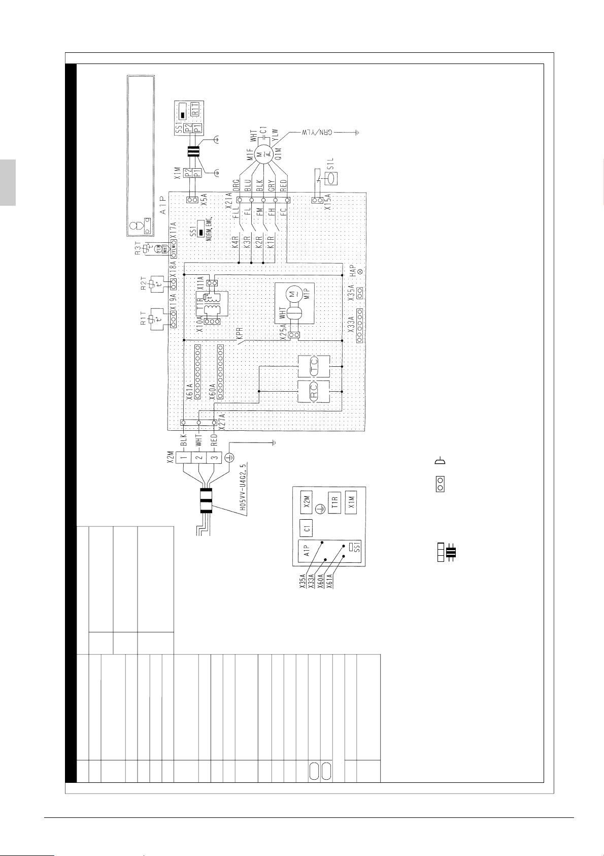
13. WIRING DIAGRAM
WIRED REMOTE CONTROLLER
(OPTIONAL PARTS)
:CONNECTER DISCRIMINATION COLOUR FOR COMPONENTS.
:CONNECTER COLOUR FOR COMPONENTS.
:CONNECTER COLOUR FOR PRINTED CIRCUIT BOARD.
FBQ60 • 71BV1 , FBQ60 • 71BVL3D048487-1
NOTE) 7 NOTE) 7
WIRING DIAGRAM
INDOOR UNIT
TO BP UNIT
CONNECTOR
(ADAPTOR FOR WIRING)
CONNECTOR
(GROUP CONTROL ADAPTOR)
CONNECTOR
(INTERFACE ADAPTOR FOR
SKY AIR SERIES)
CONNECTOR FOR OPTIONAL PARTS
X33A
X35A
X60A
X61A
CONTROL BOX
, : CONNECTOR
: TERMINAL
: FIELD WIRING
NOTES)
INSTALLATION MANUAL.
1.
3. IN CASE USING CENTRAL REMOTE CONTROLLER, CONNECT IT TO THE UNIT IN ACCORDANCE WITH THE ATTACHED
4. REMOTE CONTROLLER MODEL VARIES ACCORDING TO THE COMBINATION SYSTEM, CONFIRM ENGINEERING
2.
MATERIALS AND CATALOGS, ETC. BEFORE CONNECTING.
MATERIALS, ETC.
5. SYMBOLS SHOW AS FOLLOWS: RED: RED BLK: BLACK WHT: WHITE YLW: YELLOW
GRN: GREEN GRY: GRAY BLU: BLUE ORG: ORANGE
6. CONFIRM THE METHOD OF SETTING THE SELECTOR SWITCH (SS1) BY INSTALLATION MANUAL AND ENGINEERING
7. GROUND THE SHIELD OF THE REMOTE CONTROLLER CORD TO THE INDOOR UNIT (IN CASE OF USING SHIELD WIRE).
PRINTED CIRCUIT BOARD
CAPACITOR (M1F)
LIGHT EMITTING DIODE
(SERVICE MONITOR GREEN)
MAGNETIC RELAY (M1F)
MAGNETIC RELAY (M1P)
MOTOR (INDOOR FAN)
MOTOR (DRAIN PUMP)
THERMO SWITCH
(M1F EMBEDDED)
THERMISTOR (AIR)
THERMISTOR (LIQUID)
THERMISTOR (COIL)
SELECTOR SWITCH
(EMERGENCY)
FLOAT SWITCH
TRANSFORMER (220 - 240V/22V)
TERMINAL STRIP
TERMINAL STRIP
SIGNAL RECEIVER CIRCUIT
SIGNAL TRANSMISSION CIRCUIT
THERMISTOR (AIR)
SELECTOR SWITCH
(MAIN/SUB)
WIRED REMOTE CONTROLLER
A1P
C1
HAP K1R~4R
KPR
M1F
M1P
Q1M
R1T
R2T
R3T
SS1
S1L
T1R
X1M
X2M
RC TC
R1T
SS1
21 English
Page 23

3P156215-4C EM04A076B
(0506) HT
 Loading...