

Daikin FCQ18TAVJU, FCQ24TAVJU, FCQ30TAVJU, FCQ36TAVJU, FCQ42TAVJU Service Manual
...
Service
Manual
SiUS281811E
RZR-TA, RZQ-TA Series
Cooling Only 60 Hz
Heat Pump 60 Hz

SiUS281811E
Introduction .......................................................................................1
1. Safety Cautions...........................................................................................2
1.1 Warnings and Cautions Regarding Safety of Workers................................. 2
1.2 Warnings and Cautions Regarding Safety of Users..................................... 4
2. Icons Used ..................................................................................................7
3. Revision History ..........................................................................................8
Part 1 General Information ...............................................................9
1. Model Names and Power Supply..............................................................10
1.1 Cooling Only............................................................................................... 10
1.2 Heat Pump ................................................................................................. 11
2. External Appearance.................................................................................12
2.1 Indoor Unit.................................................................................................. 12
2.2 Outdoor Unit ............................................................................................... 13
2.3 Remote Controller ...................................................................................... 14
3. Specifications ............................................................................................15
3.1 Cooling Only............................................................................................... 15
3.2 Heat Pump ................................................................................................. 28
Part 2 Refrigerant Circuit............................................................... 41
1. Refrigerant Circuit (Piping Diagrams) .......................................................42
1.1 RZR18/24TAVJU, RZQ18/24TAVJU.......................................................... 42
1.2 RZR30/36/42/48TAVJU, RZQ30/36/42/48TAVJU...................................... 44
1.3 Indoor Unit.................................................................................................. 46
2. Functional Parts Layout ............................................................................47
2.1 RZR18/24TAVJU, RZQ18/24TAVJU.......................................................... 47
2.2 RZR30/36/42/48TAVJU, RZQ30/36/42/48TAVJU...................................... 49
Part 3 Remote Controller ................................................................ 51
1. Applicable Models .....................................................................................52
2. Names and Functions ...............................................................................53
2.1 Wired Remote Controller............................................................................ 53
2.2 Simplified Remote Controller...................................................................... 56
2.3 Wireless Remote Controller ....................................................................... 57
3. Main/Sub Setting.......................................................................................59
3.1 Wired Remote Controller (BRC1E73) ........................................................ 59
3.2 When Wireless Remote Controller is Used Together................................. 60
4. Address Setting for Wireless Remote Controller.......................................61
5. Centralized Control Group No. Setting......................................................64
5.1 BRC1E73 ................................................................................................... 64
5.2 Wireless Remote Controller ....................................................................... 66
6. Service Settings Menu, Maintenance Menu..............................................67
6.1 BRC1E73 ................................................................................................... 67
6.2 Wireless Remote Controller ....................................................................... 71
i Table of Contents

SiUS281811E
Part 4 Functions and Control .......................................................... 72
1. Operation Mode ........................................................................................73
2. Basic Control.............................................................................................74
2.1 Normal Operation ....................................................................................... 74
2.2 Compressor PI Control............................................................................... 75
2.3 Electronic Expansion Valve PI Control....................................................... 77
2.4 Cooling Operation Fan Control................................................................... 78
3. Special Control..........................................................................................79
3.1 Startup Control ........................................................................................... 79
3.2 Oil Return Control....................................................................................... 81
3.3 Defrost Control ........................................................................................... 83
3.4 Pump Down Residual Control .................................................................... 84
3.5 Restart Standby.......................................................................................... 85
3.6 Stop Control ............................................................................................... 85
4. Protection Control .....................................................................................86
4.1 High Pressure Protection Control............................................................... 86
4.2 Low Pressure Protection Control................................................................ 87
4.3 Discharge Pipe Temperature Protection Control........................................ 89
4.4 Inverter Protection Control ......................................................................... 90
5. Other Control.............................................................................................92
5.1 Demand Operation ..................................................................................... 92
5.2 Heating Operation Prohibition .................................................................... 92
6. Outline of Control (Indoor Unit) .................................................................93
6.1 Remote Controller Thermistor .................................................................... 93
6.2 Thermostat Control..................................................................................... 95
6.3 Thermostat Control with Operation Mode Set to AUTO ............................. 97
6.4 List of Swing Flap Operations .................................................................... 98
6.5 Hot Start Control (In Heating Operation Only)............................................ 99
6.6 Louver Control for Preventing Ceiling Dirt (FCQ Models Only)................ 100
6.7 Drain Pump Control.................................................................................. 101
6.8 Freeze-Up Prevention .............................................................................. 103
6.9 Heater Control (Except FTQ-TA Models) ................................................. 105
6.10 Heater Control (FTQ-TA Models) ............................................................. 106
6.11 3-Step Thermostat Processing (FTQ-TA Models).................................... 110
6.12 Fan Control (Heater Residual) (FTQ-TA Models) .................................... 111
6.13 Interlocked with External Equipment (FTQ-TA Models) ........................... 111
Part 5 Field Settings and Test Operation ..................................... 113
1. Field Setting from Remote Controller......................................................114
1.1 Wired Remote Controller.......................................................................... 114
1.2 Simplified Remote Controller.................................................................... 116
1.3 Wireless Remote Controller ..................................................................... 117
1.4 List of Field Settings for Indoor Unit ......................................................... 118
1.5 Details of Field Settings for Indoor Unit.................................................... 122
1.6 Operation Control Mode........................................................................... 137
2. Field Settings from Outdoor Unit.............................................................138
2.1 Capacity Setting ....................................................................................... 138
Table of Contents ii

SiUS281811E
2.2 Setting Mode and Monitor Mode .............................................................. 139
2.3 Setting Mode 1 ......................................................................................... 140
2.4 Setting Mode 2 ......................................................................................... 142
2.5 Monitor Mode ........................................................................................... 146
2.6 Setting of Low Noise Operation and Demand Operation ......................... 148
2.7 Setting of Refrigerant Recovery Mode ..................................................... 151
2.8 Setting of Vacuuming Mode ..................................................................... 151
2.9 Check Operation ...................................................................................... 152
2.10 Setting of Auxiliary Heater Control ........................................................... 153
2.11 Setting of Heat Pump Lockout and Emergency Heat Mode..................... 154
3. Test Operation ........................................................................................156
3.1 Check Work Prior to Turning Power Supply ON ...................................... 156
3.2 Turn Power ON ........................................................................................ 156
3.3 Test Operation.......................................................................................... 157
3.4 Error Codes and Corresponding Measures.............................................. 160
3.5 When Turning ON Power First Time ........................................................ 162
3.6 When Turning ON Power the Second Time and Subsequent.................. 162
3.7 When an Indoor Unit or Outdoor Unit has been Added,
or Indoor or Outdoor Unit PCB has been Changed.................................. 162
Part 6 Service Diagnosis ............................................................... 163
1. Servicing Items to be Confirmed .............................................................166
1.1 Troubleshooting........................................................................................ 166
1.2 Precautions for Maintenance.................................................................... 166
1.3 Refrigerant Properties (R-410A)............................................................... 168
2. Symptom-based Troubleshooting ...........................................................169
2.1 Indoor Unit Overall ................................................................................... 169
2.2 With Optional Infrared Presence/Floor Sensor......................................... 172
3. Troubleshooting with Remote Controller.................................................174
3.1 Wired Remote Controller.......................................................................... 174
3.2 Wireless Remote Controller ..................................................................... 175
4. Troubleshooting by Error Codes .............................................................177
4.1 Error Codes and Description .................................................................... 177
4.2 Error Codes - Sub Codes ......................................................................... 179
4.3 Error Code Indication by Outdoor Unit PCB............................................. 181
4.4 External Protection Device Abnormality (Except FTQ-TA)....................... 185
4.5 External Protection Device Abnormality (FTQ-TA Only) .......................... 186
4.6 Indoor Unit PCB Abnormality ................................................................... 187
4.7 Drain Level Control System (S1L) Abnormality........................................ 188
4.8 Indoor Fan Motor (M1F) Lock, Overload .................................................. 190
4.9 Indoor Fan Motor Abnormality.................................................................. 192
4.10 Blower Motor Not Running ....................................................................... 196
4.11 Indoor Fan Motor Status Abnormality....................................................... 197
4.12 Low Indoor Airflow.................................................................................... 198
4.13 Swing Flap Motor Abnormality ................................................................. 199
4.14 Power Supply Voltage Abnormality .......................................................... 201
4.15 Blower Motor Stops for Over/Under Voltage ............................................ 202
4.16 Electronic Expansion Valve Coil Abnormality, Dust Clogging .................. 203
iii Table of Contents

SiUS281811E
4.17 Drain Level Above Limit ........................................................................... 205
4.18 Capacity Determination Device Abnormality ............................................ 206
4.19 Transmission Abnormality (between Indoor Unit PCB and Fan PCB) ..... 207
4.20 Blower Motor Communication Error ......................................................... 209
4.21 Thermistor Abnormality ............................................................................ 210
4.22 Combination Abnormality (between Indoor Unit PCB and Fan PCB)....... 211
4.23 Blower Motor HP Mismatch...................................................................... 212
4.24 Indoor Blower Does Not Have Required Parameters to Function............ 213
4.25 Remote Sensor Abnormality .................................................................... 214
4.26 Infrared Presence/Floor Sensor Error ...................................................... 215
4.27 Remote Controller Thermistor Abnormality .............................................. 220
4.28 Outdoor Main PCB Abnormality ............................................................... 221
4.29 Activation of High Pressure Switch .......................................................... 222
4.30 Activation of Low Pressure Sensor .......................................................... 224
4.31 Inverter Compressor Motor Lock.............................................................. 226
4.32 Outdoor Fan Motor Abnormality ............................................................... 228
4.33 Electronic Expansion Valve Coil Abnormality........................................... 230
4.34 Discharge Pipe Temperature Abnormality ............................................... 231
4.35 Refrigerant Overcharged.......................................................................... 232
4.36 Thermistor Abnormality ............................................................................ 233
4.37 High Pressure Sensor Abnormality .......................................................... 234
4.38 Low Pressure Sensor Abnormality ........................................................... 235
4.39 PCB (for Inverter Compressor) Abnormality............................................. 236
4.40 Radiation Fin Temperature Rise Abnormality .......................................... 237
4.41 Inverter Compressor Instantaneous Overcurrent ..................................... 238
4.42 Inverter Compressor Overcurrent............................................................. 239
4.43 Inverter Compressor Startup Abnormality ................................................ 240
4.44 Transmission Error
(Between Microcomputers on the Outdoor Main PCB) ............................ 241
4.45 Inverter Circuit Capacitor High Voltage .................................................... 242
4.46 Radiation Fin Thermistor Abnormality ...................................................... 243
4.47 Refrigerant Shortage ................................................................................ 244
4.48 Power Supply Insufficient or Instantaneous Abnormality ......................... 246
4.49 Check Operation Not Executed................................................................ 248
4.50 Transmission Error between Indoor Units and Outdoor Units.................. 249
4.51 Transmission Error between Remote Controller and Indoor Unit............. 251
4.52 Transmission Error between Main and Sub Remote Controllers ............. 252
4.53 Transmission Error between Indoor and Outdoor Units in the
Same System ........................................................................................... 253
4.54 Improper Combination of Indoor and Outdoor Units,
Indoor Units and Remote Controller......................................................... 254
4.55 Incorrect Electric Heater Capacity Setting................................................ 256
4.56 Address Duplication of Centralized Controller.......................................... 257
4.57 Transmission Error between Centralized Controller and Indoor Unit ....... 258
4.58 System Not Set ........................................................................................ 259
4.59 System Abnormality, Refrigerant System Address Undefined ................. 260
5. Check ......................................................................................................261
5.1 High Pressure Check ............................................................................... 261
5.2 Low Pressure Check ................................................................................ 262
Table of Contents iv

SiUS281811E
5.3 Superheat Operation Check..................................................................... 263
5.4 Power Transistor Check ........................................................................... 264
5.5 Refrigerant Overcharge Check................................................................. 265
5.6 Refrigerant Shortage Check..................................................................... 266
5.7 Vacuuming and Dehydration Procedure .................................................. 267
5.8 List of Inverter-Related Error Codes......................................................... 268
5.9 Concept of Inverter-Related Error Codes................................................. 269
5.10 Thermistor Check ..................................................................................... 270
5.11 Pressure Sensor Check ........................................................................... 273
5.12 Broken Wire Check of the Relay Wires .................................................... 274
5.13 Fan Motor Connector Check .................................................................... 275
5.14 Electronic Expansion Valve Coil Check ................................................... 277
5.15 Fan Motor Connector Check for FTQ-TA ................................................. 280
Part 7 Appendix ............................................................................. 284
1. Wiring Diagrams......................................................................................285
1.1 Outdoor Unit ............................................................................................. 285
1.2 Indoor Unit................................................................................................ 287
v Table of Contents

SiUS281811E
Introduction
1. Safety Cautions...........................................................................................2
1.1 Warnings and Cautions Regarding Safety of Workers................................. 2
1.2 Warnings and Cautions Regarding Safety of Users..................................... 4
2. Icons Used ..................................................................................................7
3. Revision History ..........................................................................................8
Introduction 1
Safety Cautions SiUS281811E
Warning
1. Safety Cautions
Be sure to read the following safety cautions before conducting repair work.
After the repair work is complete, be sure to conduct a test operation to ensure that the equipment
operates normally, and explain the cautions for operating the product to the customer.
This manual is for the
person in charge of
maintenance and
inspection.
Caution Items The caution items are classified into Warning and Caution. The Warning items are
especially important since death or serious injury can result if they are not followed closely. The
Caution items can also lead to serious accidents under some conditions if they are not
followed. Therefore, be sure to observe all the safety caution items described below.
Pictograms This symbol indicates an item for which caution must be exercised.
The pictogram shows the item to which attention must be paid.
This symbol indicates a prohibited action.
The prohibited item or action is shown in the illustration or near the symbol.
This symbol indicates an action that must be taken, or an instruction.
The instruction is shown in the illustration or near the symbol.
1.1 Warnings and Cautions Regarding Safety of Workers
Do not store equipment in a room with fire sources (e.g., naked
flames, gas appliances, electric heaters).
Be sure to disconnect the power cable from the socket before
disassembling equipment for repair.
Working on equipment that is connected to the power supply may cause
an electrical shock.
If it is necessary to supply power to the equipment to conduct the repair or
inspect the circuits, do not touch any electrically charged sections of the
equipment.
If refrigerant gas is discharged during repair work, do not touch the
discharged refrigerant gas.
Refrigerant gas may cause frostbite.
When disconnecting the suction or discharge pipe of the
compressor at the welded section, evacuate the refrigerant gas
completely at a well-ventilated place first.
If there is gas remaining inside the compressor, the refrigerant gas or
refrigerating machine oil discharges when the pipe is disconnected, and it
may cause injury.
If refrigerant gas leaks during repair work, ventilate the area.
Refrigerant gas may generate toxic gases when it contacts flames.
2 Introduction

SiUS281811E Safety Cautions
Caution
Warning
Be sure to discharge the capacitor completely before conducting
repair work.
The step-up capacitor supplies high-voltage electricity to the electrical
components of the outdoor unit.
A charged capacitor may cause an electrical shock.
Do not turn the air conditioner on or off by plugging in or
unplugging the power cable.
Plugging in or unplugging the power cable to operate the equipment may
cause an electrical shock or fire.
Be sure to wear a safety helmet, gloves, and a safety belt when
working in a high place (more than 2 m (6.5 ft)).
Insufficient safety measures may cause a fall.
In case of R-410A refrigerant models, be sure to use pipes, flare nuts
and tools intended for the exclusive use with the R-410A refrigerant.
The use of materials for other refrigerant models may cause a serious
accident, such as a damage of refrigerant cycle or equipment failure.
Do not mix air or gas other than the specified refrigerant (R-410A) in
the refrigerant system.
If air enters the refrigerant system, an excessively high pressure results,
causing equipment damage and injury.
Do not repair electrical components with wet hands.
Working on the equipment with wet hands may cause an electrical shock.
Do not clean the air conditioner with water.
Washing the unit with water may cause an electrical shock.
Be sure to provide an earth / grounding when repairing the
equipment in a humid or wet place, to avoid electrical shocks.
Be sure to turn off the power switch and unplug the power cable
when cleaning the equipment.
The internal fan rotates at a high speed, and may cause injury.
Be sure to conduct repair work with appropriate tools.
The use of inappropriate tools may cause injury.
Introduction 3
Safety Cautions SiUS281811E
Caution
Warning
Be sure to check that the refrigerating cycle section has cooled
down enough before conducting repair work.
Working on the unit when the refrigerating cycle section is hot may cause
burns.
Conduct welding work in a well-ventilated place.
Using the welder in an enclosed room may cause oxygen deficiency.
1.2 Warnings and Cautions Regarding Safety of Users
Do not store the equipment in a room with fire sources (e.g., naked
flames, gas appliances, electric heaters).
Be sure to use parts listed in the service parts list of the applicable
model and appropriate tools to conduct repair work. Never attempt
to modify the equipment.
The use of inappropriate parts or tools may cause an electrical shock,
excessive heat generation or fire.
If the power cable and lead wires are scratched or have deteriorated,
be sure to replace them.
Damaged cable and wires may cause an electrical shock, excessive heat
generation or fire.
Do not use a joined power cable or extension cable, or share the
same power outlet with other electrical appliances, since it may
cause an electrical shock, excessive heat generation or fire.
Be sure to use an exclusive power circuit for the equipment, and
follow the local technical standards related to the electrical
equipment, the internal wiring regulations, and the instruction
manual for installation when conducting electrical work.
Insufficient power circuit capacity and improper electrical work may cause
an electrical shock or fire.
Be sure to use the specified cable for wiring between the indoor and
outdoor units.
Make the connections securely and route the cable properly so that there
is no force pulling the cable at the connection terminals.
Improper connections may cause excessive heat generation or fire.
When wiring between the indoor and outdoor units, make sure that
the terminal cover does not lift off or dismount because of the cable.
If the cover is not mounted properly, the terminal connection section may
cause an electrical shock, excessive heat generation or fire.
Do not damage or modify the power cable.
Damaged or modified power cables may cause an electrical shock or fire.
Placing heavy items on the power cable, or heating or pulling the power
cable may damage it.
4 Introduction
SiUS281811E Safety Cautions
Caution
Warning
Do not mix air or gas other than the specified refrigerant (R-410A) in
the refrigerant system.
If air enters the refrigerant system, an excessively high pressure results,
causing equipment damage and injury.
If the refrigerant gas leaks, be sure to locate the leaking point and
repair it before charging the refrigerant. After charging the
refrigerant, make sure that there is no leak.
If the leaking point cannot be located and the repair work must be
stopped, be sure to pump-down, and close the service valve, to prevent
refrigerant gas from leaking into the room. Refrigerant gas itself is
harmless, but it may generate toxic gases when it contacts flames, such
as those from fan type and other heaters, stoves and ranges.
When relocating the equipment, make sure that the new installation
site has sufficient strength to withstand the weight of the
equipment.
If the installation site does not have sufficient strength or the installation
work is not conducted securely, the equipment may fall and cause injury.
Check to make sure that the power cable plug is not dirty or loose,
then insert the plug into a power outlet securely.
If the plug is dusty or has a loose connection, it may cause an electrical
shock or fire.
When replacing the coin battery in the remote controller, be sure to
dispose of the old battery to prevent children from swallowing it.
If a child swallows the coin battery, see a doctor immediately.
Installation of a leakage breaker is necessary in some cases
depending on the conditions of the installation site, to prevent
electrical shocks.
Do not install the equipment in a place where there is a possibility of
combustible gas leaks.
If combustible gas leaks and remains around the unit, it may cause a fire.
Check to see if parts and wires are mounted and connected
properly, and if connections at the soldered or crimped terminals
are secure.
Improper installation and connections may cause excessive heat
generation, fire or an electrical shock.
If the installation platform or frame has corroded, replace it.
A corroded installation platform or frame may cause the unit to fall,
resulting in injury.
Check the earth / grounding, and repair it if the equipment is not
properly earthed / grounded.
Improper earth / grounding may cause an electrical shock.
Introduction 5
Safety Cautions SiUS281811E
Caution
Be sure to measure insulation resistance after the repair, and make
sure that the resistance is 1 M or greater.
Faulty insulation may cause an electrical shock.
Be sure to check the drainage of the indoor unit after the repair.
Faulty drainage may cause water to enter the room and wet the furniture
and floor.
Do not tilt the unit when removing it.
The water inside the unit may spill and wet the furniture and floor.
6 Introduction
SiUS281811E Icons Used
2. Icons Used
The following icons are used to attract the attention of the reader to specific information.
Icon Type of
Information
Warning Warning is used when there is danger of personal injury.
Warning
Caution Caution is used when there is danger that the reader,
Caution
Note Note provides information that is not indispensable, but
Note
Reference Reference guides the reader to other places in this binder
Reference
Description
through incorrect manipulation, may damage equipment,
lose data, get an unexpected result or have to restart (part
of) a procedure.
may nevertheless be valuable to the reader, such as tips
and tricks.
or in this manual, where he/she will find additional
information on a specific topic.
Introduction 7

Revision History SiUS281811E
3. Revision History
Month / Year Version Revised contents
04 / 2019 SiUS281811E First edition
8 Introduction

SiUS281811E
Part 1
General Information
1. Model Names and Power Supply..............................................................10
1.1 Cooling Only............................................................................................... 10
1.2 Heat Pump ................................................................................................. 11
2. External Appearance.................................................................................12
2.1 Indoor Unit.................................................................................................. 12
2.2 Outdoor Unit ............................................................................................... 13
2.3 Remote Controller ...................................................................................... 14
3. Specifications ............................................................................................15
3.1 Cooling Only............................................................................................... 15
3.2 Heat Pump ................................................................................................. 28
Part 1 General Information 9
Model Names and Power Supply SiUS281811E
Note(s)
1. Model Names and Power Supply
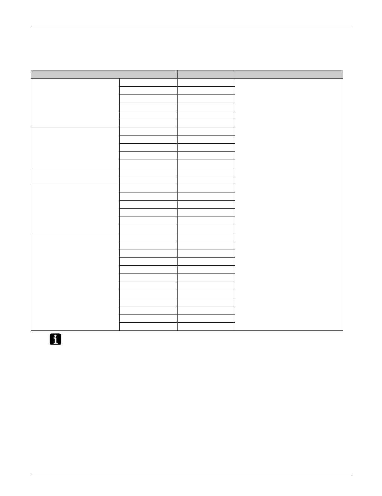
1.1 Cooling Only
Indoor unit Outdoor unit Power supply intake
Ceiling mounted cassette type
(Round flow with sensing)
Ceiling suspended type FHQ18PVJU RZR18TAVJU
Wall mounted type FAQ18TAVJU RZR18TAVJU
Ceiling mounted duct type
(High static pressure)
Multi position air handling unit FTQ18TAVJUD RZR18TAVJU
FCQ18TAVJU RZR18TAVJU
FCQ24TAVJU RZR24TAVJU
FCQ30TAVJU RZR30TAVJU
FCQ36TAVJU RZR36TAVJU
FCQ42TAVJU RZR42TAVJU
FCQ48TAVJU RZR48TAVJU
FHQ24PVJU RZR24TAVJU
FHQ30PVJU RZR30TAVJU
FHQ36MVJU RZR36TAVJU
FHQ42MVJU RZR42TAVJU
FAQ24TAVJU RZR24TAVJU
FBQ18PVJU RZR18TAVJU
FBQ24PVJU RZR24TAVJU
FBQ30PVJU RZR30TAVJU
FBQ36PVJU RZR36TAVJU
FBQ42PVJU RZR42TAVJU
FBQ48PVJU RZR48TAVJU
FTQ24TAVJUD RZR24TAVJU
FTQ30TAVJUD RZR30TAVJU
FTQ36TAVJUD RZR36TAVJU
FTQ42TAVJUD RZR42TAVJU
FTQ48TAVJUD RZR48TAVJU
FTQ18TAVJUA RZR18TAVJU
FTQ24TAVJUA RZR24TAVJU
FTQ30TAVJUA RZR30TAVJU
FTQ36TAVJUA RZR36TAVJU
FTQ42TAVJUA RZR42TAVJU
FTQ48TAVJUA RZR48TAVJU
Indoor unit: 1 phase, 208/230 V, 60 Hz
Outdoor unit: 1 phase, 208/230 V, 60 Hz
1. Power supply intake: outdoor unit
2. VJ: 1 phase, 208/230 V, 60 Hz
U (VJU): Standard Symbol
10 Part 1 General Information
SiUS281811E Model Names and Power Supply
Note(s)
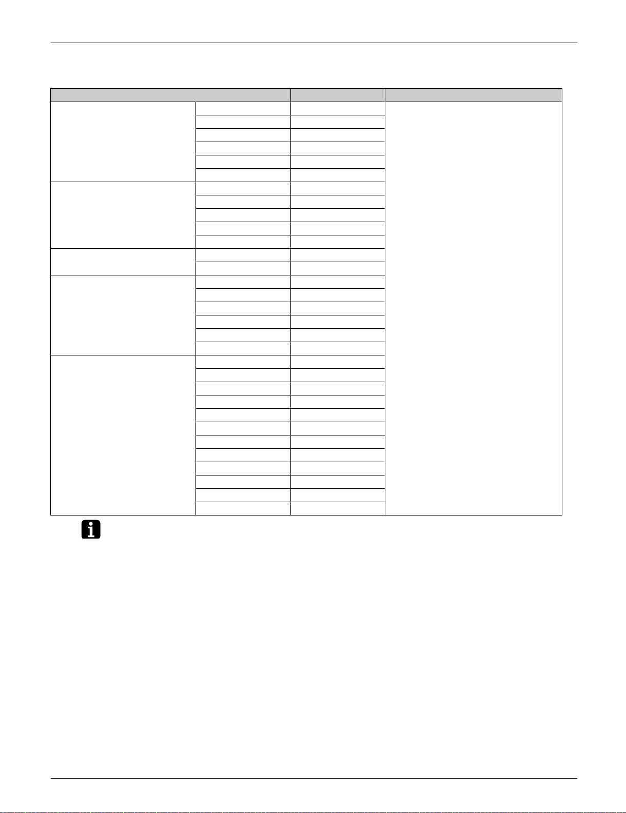
1.2 Heat Pump
Indoor unit Outdoor unit Power supply intake
Ceiling mounted cassette type
(Round flow with sensing)
Ceiling suspended type FHQ18PVJU RZQ18TAVJU
Wall mounted type FAQ18TAVJU RZQ18TAVJU
Ceiling mounted duct type
(High static pressure)
Multi position air handling unit FTQ18TAVJUD RZQ18TAVJU
FCQ18TAVJU RZQ18TAVJU
FCQ24TAVJU RZQ24TAVJU
FCQ30TAVJU RZQ30TAVJU
FCQ36TAVJU RZQ36TAVJU
FCQ42TAVJU RZQ42TAVJU
FCQ48TAVJU RZQ48TAVJU
FHQ24PVJU RZQ24TAVJU
FHQ30PVJU RZQ30TAVJU
FHQ36MVJU RZQ36TAVJU
FHQ42MVJU RZQ42TAVJU
FAQ24TAVJU RZQ24TAVJU
FBQ18PVJU RZQ18TAVJU
FBQ24PVJU RZQ24TAVJU
FBQ30PVJU RZQ30TAVJU
FBQ36PVJU RZQ36TAVJU
FBQ42PVJU RZQ42TAVJU
FBQ48PVJU RZQ48TAVJU
FTQ24TAVJUD RZQ24TAVJU
FTQ30TAVJUD RZQ30TAVJU
FTQ36TAVJUD RZQ36TAVJU
FTQ42TAVJUD RZQ42TAVJU
FTQ48TAVJUD RZQ48TAVJU
FTQ18TAVJUA RZQ18TAVJU
FTQ24TAVJUA RZQ24TAVJU
FTQ30TAVJUA RZQ30TAVJU
FTQ36TAVJUA RZQ36TAVJU
FTQ42TAVJUA RZQ42TAVJU
FTQ48TAVJUA RZQ48TAVJU
Indoor unit: 1 phase, 208/230 V, 60 Hz
Outdoor unit: 1 phase, 208/230 V, 60 Hz
1. Power supply intake: outdoor unit
2. VJ: 1 phase, 208/230 V, 60 Hz
U (VJU): Standard Symbol
Part 1 General Information 11
External Appearance SiUS281811E
2. External Appearance
2.1 Indoor Unit
Ceiling Mounted Cassette Type (Round Flow with Sensing)
FCQ18TAVJU
FCQ24TAVJU
FCQ30TAVJU
FCQ36TAVJU
FCQ42TAVJU
FCQ48TAVJU
Shown with BYCQ125B-W1
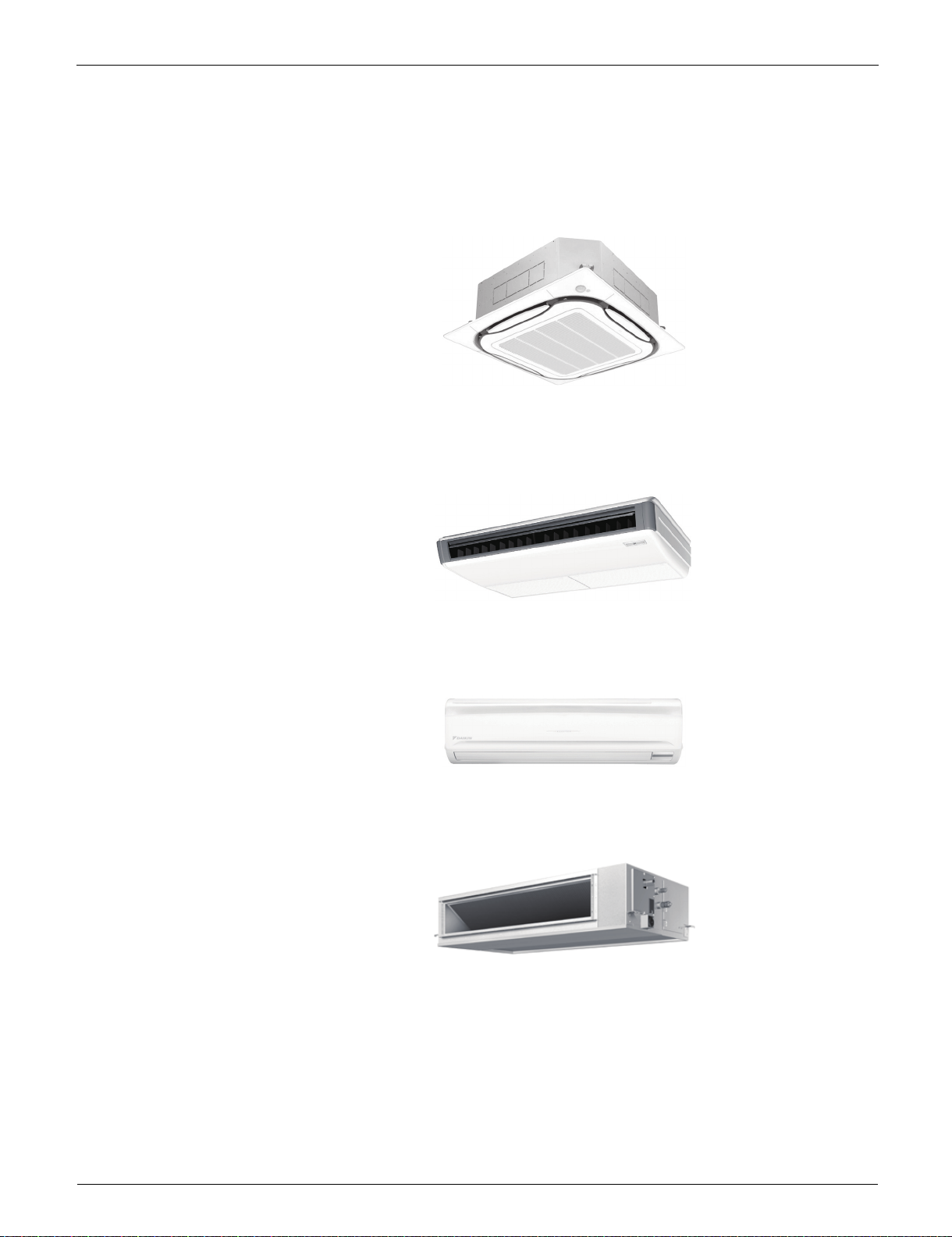
Ceiling Suspended Type
FHQ18PVJU
FHQ24PVJU
FHQ30PVJU
FHQ36MVJU
FHQ42MVJU
Wall Mounted Type
FAQ18TAVJU
FAQ24TAVJU
Ceiling Mounted Duct Type (High Static Pressure)
FBQ18PVJU
FBQ24PVJU
FBQ30PVJU
FBQ36PVJU
FBQ42PVJU
FBQ48PVJU
12 Part 1 General Information
SiUS281811E External Appearance
Multi Position Air Handling Unit
FTQ18TAVJUD, FTQ18TAVJUA
FTQ24TAVJUD, FTQ24TAVJUA
FTQ30TAVJUD, FTQ30TAVJUA
FTQ36TAVJUD, FTQ36TAVJUA
FTQ42TAVJUD, FTQ42TAVJUA
FTQ48TAVJUD, FTQ48TAVJUA
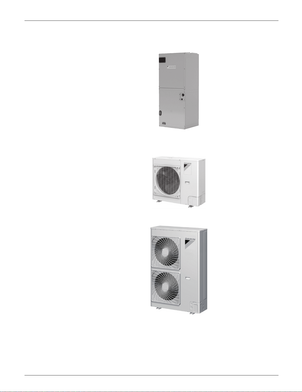
2.2 Outdoor Unit
RZR18TAVJU
RZR24TAVJU
RZQ18TAVJU
RZQ24TAVJU
RZR30TAVJU
RZR36TAVJU
RZR42TAVJU
RZR48TAVJU
RZQ30TAVJU
RZQ36TAVJU
RZQ42TAVJU
RZQ48TAVJU
Part 1 General Information 13
External Appearance SiUS281811E
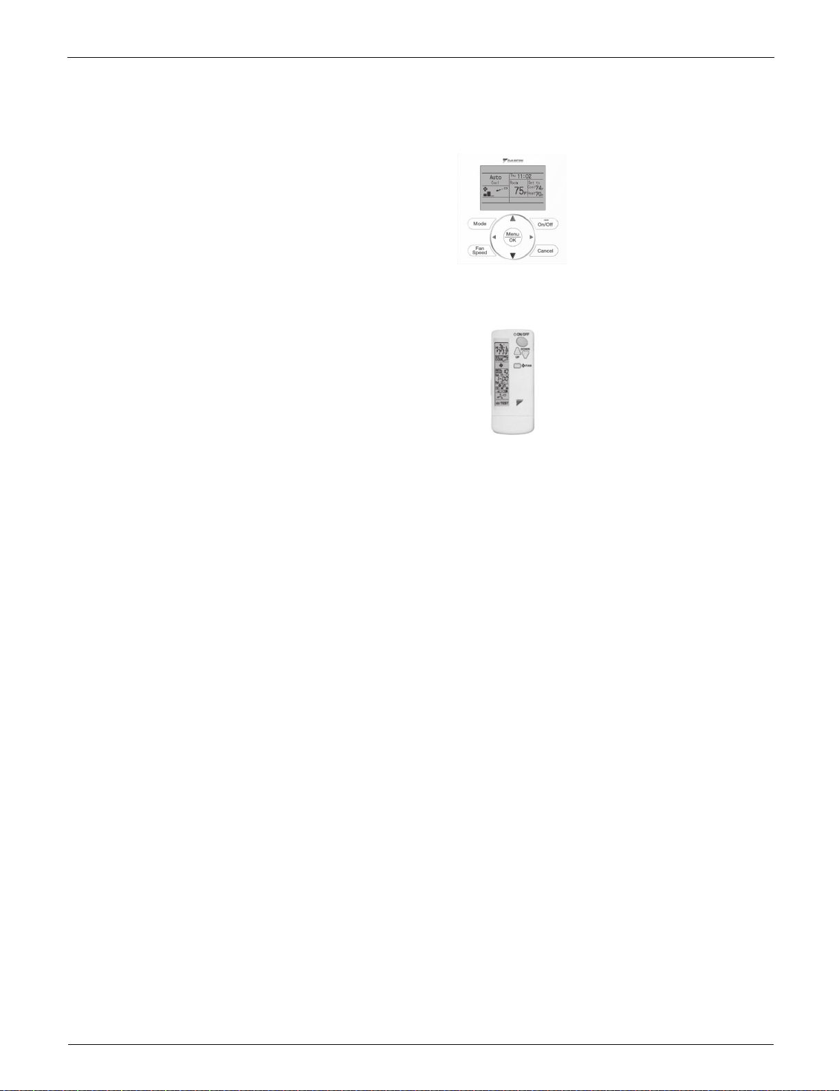
2.3 Remote Controller
Wired remote controller
BRC1E73
Wireless remote controller
BRC7E83 (FHQ)
BRC7E818 (FAQ)
BRC4C82 (FBQ (1), FTQ)
BRC082A43 (FBQ (1))
1. For FBQ series, the fan step control is different according to the wireless remote controller used.
BRC4C82 (Fan: 2 steps)
BRC082A43 (Fan: 3 steps)
14 Part 1 General Information
SiUS281811E Specifications
3. Specifications
3.1 Cooling Only
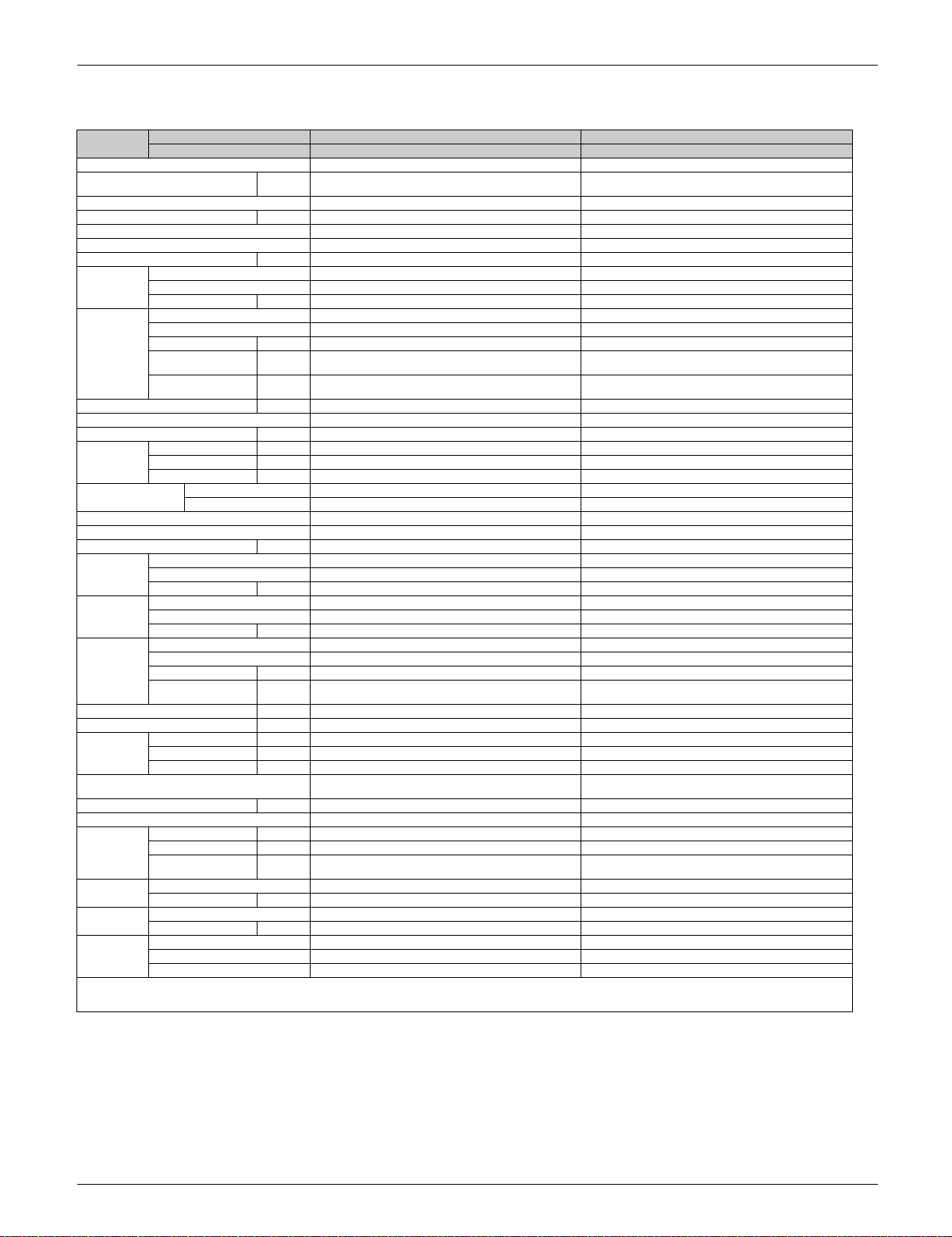
3.1.1 Ceiling Mounted Cassette Type (Round Flow with Sensing)
Model
name
Power supply 1 phase, 208/230 V, 60 Hz 1 phase, 208/230 V, 60 Hz
1 2 Cooling capacity Btu/h
SEER (Rated) 18.6 18.5
EER (Rated) Btu/h∙W 13.0 12.0
Indoor unit FCQ18TAVJU FCQ24TAVJU
Casing color Galvanized steel plate Galvanized steel plate
Dimensions: (H×W×D) in (mm) 10–1/16 × 33–1/16 × 33–1/16 (256 × 840 × 840) 10–1/16 × 33–1/16 × 33–1/16 (256 × 840 × 840)
Coil Type Cross fin coil Cross fin coil
Fan Model QTS48C15M QTS48C15M
Sound pressure level (H/M/L) dB (A) 35.5/32.0/28.0 36.0/32.0/28.0
Air filter ——
Weight lbs (kg) 63 (28.5) 63 (28.5)
Connecting
Pipes
Remote controller
(option)
Decoration
panels
(option)
Outdoor unit RZR18TAVJU RZR24TAVJU
Casing color Ivory white Ivory white
Dimensions: (H×W×D) in (mm) 39 × 37 × 12–5/8 (990 × 940 × 320) 39 × 37 × 12–5/8 (990 × 940 × 320)
Coil Type Cross fin coil Cross fin coil
Compressor Model 2YC63ABXDD 2YC63ABXDD
Fan Model P51J11F P51J11F
Weight lbs (kg) 172 (78) 172 (78)
Sound pressure level dB(A) 61 61
Connecting
Pipes
Safety devices High pressure switch, Outdoor fan driver overload
Capacity Control % 14-100 14-100
Refrigerant control Electronic expansion valve Electronic expansion valve
Ref.
piping
Refrigerant Model R-410A R-410A
Ref. oil Model DAPHNE FVC50K DAPHNE FVC50K
Drawing
No
Notes:
1 Indoor temp. : 80°FDB (26.7°CDB), 67°FWB (19.4°CWB) / outdoor temp. : 95°FDB (35.0°CDB) / Equivalent piping length : 25 ft (7.6m), level difference : 0 ft (0m).
2 Capacities are net, including a deduction for cooling for indoor fan motor heat.
Indoor unit FCQ18TAVJU FCQ24TAVJU
Outdoor unit RZR18TAVJU RZR24TAVJU
(kW)
Rows×Stages×FPI 3 × (12 + 15 × 2) × (20 + 21 × 2) 3 × (12 + 15 × 2) × (20 + 21 × 2)
Face area ft² (m
Type Turbo fan Turbo fan
Motor output W 48 48
Airflow rate (H/M/L) cfm
External static
pressure
Liquid Pipe in (mm) 3/8 (9.5) (Flare connection) 3/8 (9.5) (Flare connection)
Gas Pipe in (mm) 5/8 (15.9) (Flare connection) 5/8 (15.9) (Flare connection)
Drain Pipe in (mm) VP25 (External dia. 1–1/4 (32), internal dia. 1 (26)) VP25 (External dia. 1–1/4 (32), internal dia. 1 (26))
Wired BRC1E73, BRC2A71 BRC1E73, BRC2A71
Wireless — —
Model BYCQ125B–W1 / BYCQ125BGW1 BYCQ125B–W1 / BYCQ125BGW1
Color Fresh white Fresh white
Dimensions:
(H×W×D)
Air filter Resin net (with mold resistance) Resin net (With mold resistance)
Weight lbs (kg) 12.2 (5.5) / 22.1 (10.0) 12.2 (5.5) / 22.1 (10.0)
Rows×Stages×FPI 2 × 44 × 19 2 × 44 × 19
Face area ft² (m
Type Hermetically sealed swing type Hermetically sealed swing type
Motor output kW 1.9 1.9
Type Propeller fan Propeller fan
Motor output W 200 200
Airflow rate cfm
Liquid Pipe in (mm) 3/8 (9.5) (Flare connection) 3/8 (9.5) (Flare connection)
Gas Pipe in (mm) 5/8 (15.9) (Flare connection) 5/8 (15.9) (Flare connection)
Drain Pipe in (mm) 1 (26) (Hole) 1 (26) (Hole)
Standard length ft (m) 25 (7.6) 25 (7.6)
Max. length ft (m) 164 (50) 164 (50)
Max. height
difference
Charge lbs (kg) 6.4 (2.9) 6.4 (2.9)
Charge L 1.08 1.08
Specification C: 4D115509 C: 4D115509
Sound (indoor) C: 4D087483B C: 4D087474B
Sound (outdoor) C: 4D101948E C: 4D101948E
2
) 4.59 (0.427) 4.59 (0.427)
3
/min)
(m
O
inH
2
(Pa)
in (mm) 2 × 37–3/8 × 37–3/8 / 5–1/8 × 37–3/8 × 37–3/8
2
) 9.5 (0.88) 9.5 (0.88)
3
/min)
(m
protector, Inverter overload protector, Fusible plugs, Fuse
ft (m)
(50 × 950 × 950 / 130 × 950 × 950)
18,000 (5.3) 24,000 (7.0)
742/618/477 (21.0/17.5/13.5) 777/618/477 (22.0/17.5/13.5)
——
2 × 37–3/8 × 37–3/8 / 5–1/8 × 37–3/8 × 37–3/8
(50 × 950 × 950 / 130 × 950 × 950)
2,682 (76) 2,682 (76)
High pressure switch, Outdoor fan driver overload
protector, Inverter overload protector, Fusible plugs, Fuse
98 (30) 98 (30)
Part 1 General Information 15
Specifications SiUS281811E
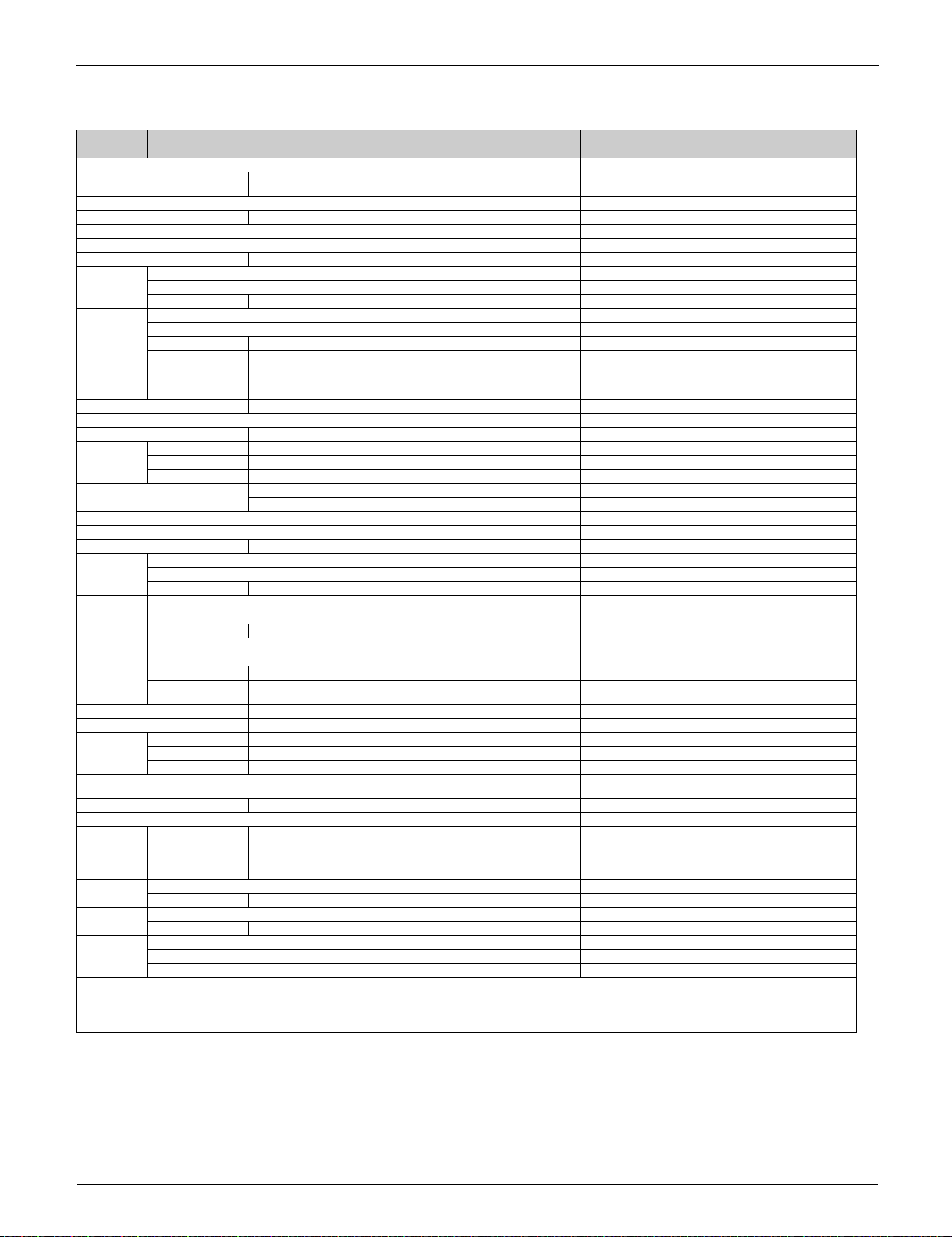
Model
name
Indoor unit FCQ30TAVJU FCQ36TAVJU
Outdoor unit RZR30TAVJU RZR36TAVJU
Power supply 1 phase, 208/230 V, 60 Hz 1 phase, 208/230 V, 60 Hz
1 2 Cooling capacity Btu/h
(kW)
30,000 (8.8) 36,000 (10.6)
SEER (Rated) 17.2 17.6
EER (Rated) Btu/h∙W 9.3 11.4
Indoor unit FCQ30TAVJU FCQ36TAVJU
Casing color Galvanized steel plate Galvanized steel plate
Dimensions: (H×W×D) in (mm) 11–23/32 × 33–1/16 × 33–1/16 (298 × 840 × 840) 11–23/32 × 33–1/16 × 33–1/16 (298 × 840 × 840)
Coil Type Cross fin coil Cross fin coil
Rows×Stages×FPI 3 × 18 × (20 + 21 × 2) 3 × 18 × (20 + 21 × 2)
Face area ft² (m
2
) 5.92 (0.550) 5.92 (0.550)
Fan Model QTS48C15M QTS48C15M
Type Turbo fan Turbo fan
Motor output W 106 106
Airflow rate (H/M/L) cfm
External static
pressure
(m
inH
(Pa)
3
/min)
2
O
1,112/918/671 (31.5/26.0/19.0) 1,165/918/671 (33.0/26.0/19.0)
——
Sound pressure level (H/M/L) dB(A) 43.5/38.0/32.0 44.0/38.0/32.0
Air filter ——
Weight lbs (kg) 70 (31.5) 70 (31.5)
Connecting
Pipes
Liquid Pipe in (mm) 3/8 (9.5) (Flare connection) 3/8 (9.5) (Flare connection)
Gas Pipe in (mm) 5/8 (15.9) (Flare connection) 5/8 (15.9) (Flare connection)
Drain Pipe in (mm) VP25 (External dia. 1–1/4 (32), internal dia. 1 (26)) VP25 (External dia. 1–1/4 (32), internal dia. 1 (26))
Remote controller
(option)
Decoration
panels
(option)
Wired BRC1E73, BRC2A71 BRC1E73, BRC2A71
Wireless — —
Model BYCQ125B–W1 / BYCQ125BGW1 BYCQ125B–W1 / BYCQ125BGW1
Color Fresh white Fresh white
Dimensions:
(H×W×D)
in (mm) 2 × 37–3/8 × 37–3/8 / 5–1/8 × 37–3/8 × 37–3/8
(50 × 950 × 950 / 130 × 950 × 950)
2 × 37–3/8 × 37–3/8 / 5–1/8 × 37–3/8 × 37–3/8
(50 × 950 × 950 / 130 × 950 × 950)
Air filter Resin net (with mold resistance) Resin net (with mold resistance)
Weight lbs (kg) 12.2 (5.5) / 22.1 (10.0) 12.2 (5.5) / 22.1 (10.0)
Outdoor unit RZR30TAVJU RZR36TAVJU
Casing color Ivory white Ivory white
Dimensions: (H×W×D) in (mm) 52–15/16 × 35–7/16 × 12–5/8 (1,345 × 900 × 320) 52–15/16 × 35–7/16 × 12–5/8 (1,345 × 900 × 320)
Coil Type Cross fin coil Cross fin coil
Rows×Stages×FPI 2 × 60 × 19 2 × 60 × 19
Face area ft² (m
2
) 12.2 (1.134) 12.2 (1.134)
Compressor Model 2YC90GXD#D 2YC90GXD#D
Type Hermetically sealed swing type Hermetically sealed swing type
Motor output kW 3.5 3.5
Fan Model P47N P47N
Type Propeller fan Propeller fan
Motor output W 70 × 2 70 × 2
Airflow rate cfm
(m
3
/min)
3,741 (106) 3,741 (106)
Weight lbs (kg) 225 (102) 225 (102)
Sound pressure level dB(A) 59 59
Connecting
Pipes
Liquid Pipe in (mm) 3/8 (9.5) (Flare connection) 3/8 (9.5) (Flare connection)
Gas Pipe in (mm) 5/8 (15.9) (Flare connection) 5/8 (15.9) (Flare connection)
Drain Pipe in (mm) 1 (26) (Hole) 1 (26) (Hole)
Safety devices High pressure switch, Outdoor fan driver overload
protector, Inverter overload protector, Fusible plugs, Fuse
High pressure switch, Outdoor fan driver overload
protector, Inverter overload protector, Fusible plugs, Fuse
Capacity Control % 14-100 14-100
Refrigerant control Electronic expansion valve Electronic expansion valve
Ref.
piping
Standard length ft (m) 25 (7.6) 25 (7.6)
Max. length ft (m) 230 (70) 230 (70)
Max. height
difference
ft (m)
98 (30) 98 (30)
Refrigerant Model R-410A R-410A
Charge lbs (kg) 7.9 (3.6) 7.9 (3.6)
Ref. oil Model DAPHNE FVC50K DAPHNE FVC50K
Charge L 1.52 1.52
Drawing
No
Specification C: 4D115511 C: 4D115511
Sound (indoor) C: 4D087479B C: 4D087475B
Sound (outdoor) C: 4D101950E C: 4D101950E
Notes:
1 Indoor temp. : 80°FDB (26.7°CDB), 67°FWB (19.4°CWB) / outdoor temp. : 95°FDB (35.0°CDB) / Equivalent piping length : 25 ft (7.6m), level difference : 0 ft (0m).
2 Capacities are net, including a deduction for cooling for indoor fan motor heat.
16 Part 1 General Information

SiUS281811E Specifications
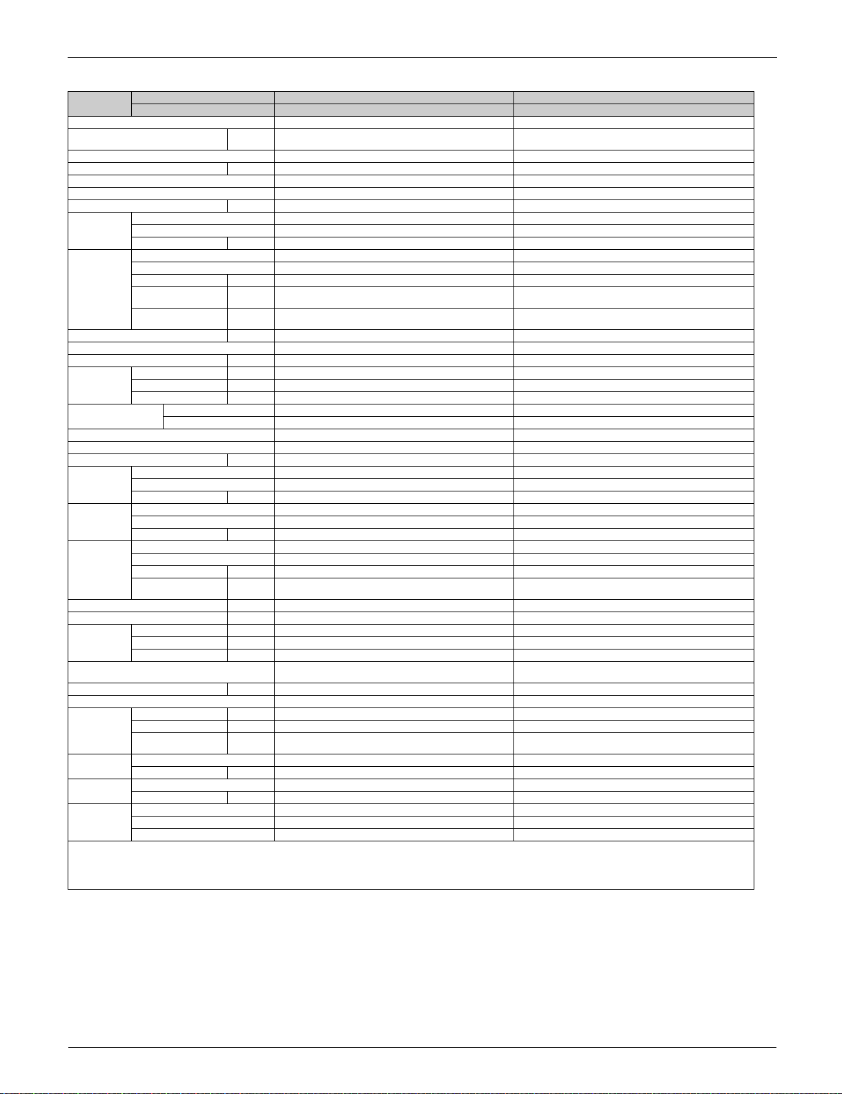
Model
name
Indoor unit FCQ42TAVJU FCQ48TAVJU
Outdoor unit RZR42TAVJU RZR48TAVJU
Power supply 1 phase, 208/230 V, 60 Hz 1 phase, 208/230 V, 60 Hz
1 2 Cooling capacity Btu/h
(kW)
42,000 (12.3) 48,000 (14.1)
SEER (Rated) 17.0 17.0
EER (Rated) Btu/h∙W 10.3 9.0
Indoor unit FCQ42TAVJU FCQ48TAVJU
Casing color Galvanized steel plate Galvanized steel plate
Dimensions: (H×W×D) in (mm) 11–23/32 × 33–1/16 × 33–1/16 (298 × 840 × 840) 11–23/32 × 33–1/16 × 33–1/16 (298 × 840 × 840)
Coil Type Cross fin coil Cross fin coil
Rows×Stages×FPI 3 × 18 × (20 + 21 × 2) 3 × 18 × (20 + 21 × 2)
Face area ft² (m
2
) 5.92 (0.550) 5.92 (0.550)
Fan Model QTS48C15M QTS48C15M
Type Turbo fan Turbo fan
Motor output W 106 106
Airflow rate (H/M/L) cfm
External static
pressure
(m
inH
(Pa)
3
/min)
2
O
1,218/971/742 (34.5/27.5/21.0) 1,218/971/742 (34.5/27.5/21.0)
——
Sound pressure level (H/M/L) dB(A) 45.0/40.0/35.0 45.0/40.0/35.0
Air filter ——
Weight lbs (kg) 70 (31.5) 70 (31.5)
Connecting
Pipes
Liquid Pipe in (mm) 3/8 (9.5) (Flare connection) 3/8 (9.5) (Flare connection)
Gas Pipe in (mm) 5/8 (15.9) (Flare connection) 5/8 (15.9) (Flare connection)
Drain Pipe in (mm) VP25 (External dia. 1–1/4 (32), internal dia. 1 (26)) VP25 (External dia. 1–1/4 (32), internal dia. 1 (26))
Remote controller
(option)
Decoration
panels
(option)
Wired BRC1E73, BRC2A71 BRC1E73, BRC2A71
Wireless — —
Model BYCQ125B–W1 / BYCQ125BGW1 BYCQ125B–W1 / BYCQ125BGW1
Color Fresh white Fresh white
Dimensions:
(H×W×D)
in (mm) 2 × 37–3/8 × 37–3/8 / 5–1/8 × 37–3/8 × 37–3/8
(50 × 950 × 950 / 130 × 950 × 950)
2 × 37–3/8 × 37–3/8 / 5–1/8 × 37–3/8 × 37–3/8
(50 × 950 × 950 / 130 × 950 × 950)
Air filter Resin net (with mold resistance) Resin net (with mold resistance)
Weight lbs (kg) 12.2 (5.5) / 22.1 (10.0) 12.2 (5.5) / 22.1 (10.0)
Outdoor unit RZR42TAVJU RZR48TAVJU
Casing color Ivory white Ivory white
Dimensions: (H×W×D) in (mm) 52–15/16 × 35–7/16 × 12–5/8 (1,345 × 900 × 320) 52–15/16 × 35–7/16 × 12–5/8 (1,345 × 900 × 320)
Coil Type Cross fin coil Cross fin coil
Rows×Stages×FPI 2 × 60 × 19 2 × 60 × 19
Face area ft² (m
2
) 12.2 (1.134) 12.2 (1.134)
Compressor Model 2YC90GXD#D 2YC90GXD#D
Type Hermetically sealed swing type Hermetically sealed swing type
Motor output kW 3.5 3.5
Fan Model P47N P47N
Type Propeller fan Propeller fan
Motor output W 70 × 2 70 × 2
Airflow rate cfm
(m
3
/min)
3,741 (106) 3,741 (106)
Weight lbs (kg) 225 (102) 225 (102)
Sound pressure level dB(A) 59 59
Connecting
Pipes
Liquid Pipe in (mm) 3/8 (9.5) (Flare connection) 3/8 (9.5) (Flare connection)
Gas Pipe in (mm) 5/8 (15.9) (Flare connection) 5/8 (15.9) (Flare connection)
Drain Pipe in (mm) 1 (26) (Hole) 1 (26) (Hole)
Safety devices High pressure switch, Outdoor fan driver overload
protector, Inverter overload protector, Fusible plugs, Fuse
High pressure switch, Outdoor fan driver overload
protector, Inverter overload protector, Fusible plugs, Fuse
Capacity Control % 14-100 14-100
Refrigerant control Electronic expansion valve Electronic expansion valve
Ref.
piping
Standard length ft (m) 25 (7.6) 25 (7.6)
Max. length ft (m) 230 (70) 230 (70)
Max. height
difference
ft (m)
98 (30) 98 (30)
Refrigerant Model R-410A R-410A
Charge lbs (kg) 7.9 (3.6) 7.9 (3.6)
Ref. oil Model DAPHNE FVC50K DAPHNE FVC50K
Charge L 1.52 1.52
Drawing
No
Specification C: 4D115511 C: 4D115511
Sound (indoor) C: 4D087476B C: 4D087476B
Sound (outdoor) C: 4D101950E C: 4D101950E
Notes:
1 Indoor temp. : 80°FDB (26.7°CDB), 67°FWB (19.4°CWB) / outdoor temp. : 95°FDB (35.0°CDB) / Equivalent piping length : 25 ft (7.6m), level difference : 0 ft (0m).
2 Capacities are net, including a deduction for cooling for indoor fan motor heat.
Part 1 General Information 17
Specifications SiUS281811E
3.1.2 Ceiling Suspended Type
Model
name
Power supply 1 phase, 208/230 V, 60 Hz 1 phase, 208/230 V, 60 Hz
1 2 Cooling capacity Btu/h
SEER (Rated) 16.3 16.6
EER (Rated) Btu/h∙W 12.9 11.3
Indoor unit FHQ18PVJU FHQ24PVJU
Casing color White (10Y9/0.5) White (10Y9/0.5)
Dimensions: (H×W×D) in (mm) 7–11/16 × 62–5/8 × 26–3/4 (195 × 1,590 × 680) 7–11/16 × 62–5/8 × 26–3/4 (195 × 1,590 × 680)
Coil Type Cross fin coil Cross fin coil
Fan Model — —
Air filter Resin net (with mold resistance) Resin net (with mold resistance)
Weight lbs (kg) 90 (19.8) 90 (19.8)
Connecting
Pipes
Remote controller
(option)
Outdoor unit RZR18TAVJU RZR24TAVJU
Casing color Ivory white Ivory white
Dimensions: (H×W×D) in (mm) 39 × 37 × 12–5/8 (990 × 940 × 320) 39 × 37 × 12–5/8 (990 × 940 × 320)
Coil Type Cross fin coil Cross fin coil
Compressor Model 2YC63ABXDD 2YC63ABXDD
Fan Model P51J11F P51J11F
Weight lbs (kg) 172 (78) 172 (78)
Sound pressure level dB(A) 61 61
Connecting
Pipes
Safety devices High pressure switch, Outdoor fan driver overload
Capacity Control % 14-100 14-100
Refrigerant control Electronic expansion valve Electronic expansion valve
Ref.
piping
Refrigerant Model R-410A R-410A
Ref. oil Model DAPHNE FVC50K DAPHNE FVC50K
Drawing
No
Notes:
1 Indoor temp. : 80°FDB (26.7°CDB), 67°FWB (19.4°CWB) / outdoor temp. : 95°FDB (35.0°CDB) / Equivalent piping length : 25 ft (7.6m), level difference : 0 ft (0m).
2 Capacities are net, including a deduction for cooling for indoor fan motor heat.
Indoor unit FHQ18PVJU FHQ24PVJU
Outdoor unit RZR18TAVJU RZR24TAVJU
(kW)
Rows×Stages×FPI 2 × 12 × 15 + 2 × 10 × 15 2 × 12 × 15 + 2 × 10 × 15
Face area ft² (m
Type Sirocco fan Sirocco fan
Motor output W 130 130
Airflow rate (H/L) cfm
External static
pressure
Liquid Pipe in (mm) 3/8 (9.5) (Flare connection) 3/8 (9.5) (Flare connection)
Gas Pipe in (mm) 5/8 (15.9) (Flare connection) 5/8 (15.9) (Flare connection)
Drain Pipe in (mm) VP20 (External dia. 1 (26), internal dia. 3/4 (19.1)) VP20 (External dia. 1 (26), internal dia. 3/4 (19.1))
Wired BRC1E73 BRC1E73
Wireless BRC7E83 BRC7E83
Rows×Stages×FPI 2 × 44 × 19 2 × 44 × 19
Face area ft² (m
Type Hermetically sealed swing type Hermetically sealed swing type
Motor output kW 1.9 1.9
Type Propeller fan Propeller fan
Motor output W 200 200
Airflow rate cfm
Liquid Pipe in (mm) 3/8 (9.5) (Flare connection) 3/8 (9.5) (Flare connection)
Gas Pipe in (mm) 5/8 (15.9) (Flare connection) 5/8 (15.9) (Flare connection)
Drain Pipe in (mm) 1 (26) (Hole) 1 (26) (Hole)
Standard length ft (m) 25 (7.6) 25 (7.6)
Max. length ft (m) 164 (50) 164 (50)
Max. height
difference
Charge lbs (kg) 6.4 (2.9) 6.4 (2.9)
Charge L 1.08 1.08
Specification C: 4D115558A C: 4D115558A
Sound (outdoor) C: 4D101948E C: 4D101948E
2
) 3.66 (0.34) + 2.95 (0.27) 3.66 (0.34) + 2.95 (0.27)
3
/min)
(m
inH
O
2
(Pa)
2
) 9.5 (0.88) 9.5 (0.88)
3
/min)
(m
protector, Inverter overload protector, Fusible plugs, Fuse
ft (m)
18,000 (5.3) 24,000 (7.0)
790/670 (22.4/19.0) 790/670 (22.4/19.0)
——
2,682 (76) 2,682 (76)
High pressure switch, Outdoor fan driver overload
protector, Inverter overload protector, Fusible plugs, Fuse
98 (30) 98 (30)
18 Part 1 General Information
SiUS281811E Specifications
Model
name
Indoor unit FHQ30PVJU FHQ36MVJU
Outdoor unit RZR30TAVJU RZR36TAVJU
Power supply 1 phase, 208/230 V, 60 Hz 1 phase, 208/230 V, 60 Hz
1 2 Cooling capacity Btu/h
(kW)
30,000 (8.8) 36,000 (10.6)
SEER (Rated) 16.0 14.0
EER (Rated) Btu/h∙W 10.5 9.5
Indoor unit FHQ30PVJU FHQ36MVJU
Casing color White (10Y9/0.5) White (10Y9/0.5)
Dimensions: (H×W×D) in (mm) 7–11/16 × 62–5/8 × 26–3/4 (195 × 1,590 × 680) 7–11/16 × 62–5/8 × 26–3/4 (195 × 1,590 × 680)
Coil Type Cross fin coil Cross fin coil
Rows×Stages×FPI 2 × 12 × 15 + 2 × 10 × 15 2 × 12 × 15 + 2 × 10 × 15
Face area ft² (m
2
) 3.66 (0.34) + 2.95 (0.27) 3.66 (0.34) + 2.95 (0.27)
Fan Model — —
Type Sirocco fan Sirocco fan
Motor output W 130 130
Airflow rate (H/L) cfm
External static
pressure
(m
inH
(Pa)
3
/min)
2
O
790/670 (22.4/19.0) 830/670 (23.5/19.0)
——
Air filter Resin net (with mold resistance) Resin net (with mold resistance)
Weight lbs (kg) 90 (19.8) 90 (19.8)
Connecting
Pipes
Liquid Pipe in (mm) 3/8 (9.5) (Flare connection) 3/8 (9.5) (Flare connection)
Gas Pipe in (mm) 5/8 (15.9) (Flare connection) 5/8 (15.9) (Flare connection)
Drain Pipe in (mm) VP20 (External dia. 1 (26), internal dia. 3/4 (19.1)) VP20 (External dia. 1 (26), internal dia. 3/4 (19.1))
Remote controller
(option)
Wired BRC1E73 BRC1E73
Wireless BRC7E83 BRC7E83
Outdoor unit RZR30TAVJU RZR36TAVJU
Casing color Ivory white Ivory white
Dimensions: (H×W×D) in (mm) 52–15/16 × 35–7/16 × 12–5/8 (1,345 × 900 × 320) 52–15/16 × 35–7/16 × 12–5/8 (1,345 × 900 × 320)
Coil Type Cross fin coil Cross fin coil
Rows×Stages×FPI 2 × 60 × 19 2 × 60 × 19
Face area ft² (m
2
) 12.2 (1.134) 12.2 (1.134)
Compressor Model 2YC90GXD#D 2YC90GXD#D
Type Hermetically sealed swing type Hermetically sealed swing type
Motor output kW 3.5 3.5
Fan Model P47N P47N
Type Propeller fan Propeller fan
Motor output W 70 × 2 70 × 2
Airflow rate cfm
(m
3
/min)
3,741 (106) 3,741 (106)
Weight lbs (kg) 225 (102) 225 (102)
Sound pressure level dB(A) 59 59
Connecting
Pipes
Liquid Pipe in (mm) 3/8 (9.5) (Flare connection) 3/8 (9.5) (Flare connection)
Gas Pipe in (mm) 5/8 (15.9) (Flare connection) 5/8 (15.9) (Flare connection)
Drain Pipe in (mm) 1 (26) (Hole) 1 (26) (Hole)
Safety devices High pressure switch, Outdoor fan driver overload
protector, Inverter overload protector, Fusible plugs, Fuse
High pressure switch, Outdoor fan driver overload
protector, Inverter overload protector, Fusible plugs, Fuse
Capacity Control % 14-100 14-100
Refrigerant control Electronic expansion valve Electronic expansion valve
Ref.
piping
Standard length ft (m) 25 (7.6) 25 (7.6)
Max. length ft (m) 230 (70) 230 (70)
Max. height
difference
ft (m)
98 (30) 98 (30)
Refrigerant Model R-410A R-410A
Charge lbs (kg) 7.9 (3.6) 7.9 (3.6)
Ref. oil Model DAPHNE FVC50K DAPHNE FVC50K
Charge L 1.52 1.52
Drawing
No
Notes:
1 Indoor temp. : 80°FDB (26.7°CDB), 67°FWB (19.4°CWB) / outdoor temp. : 95°FDB (35.0°CDB) / Equivalent piping length : 25 ft (7.6m), level difference : 0 ft (0m).
2 Capacities are net, including a deduction for cooling for indoor fan motor heat.
Specification C: 4D115560A C: 4D115560A
Sound (outdoor) C: 4D101950E C: 4D101950E
Part 1 General Information 19
Specifications SiUS281811E
Model
name
Indoor unit FHQ42MVJU
Outdoor unit RZR42TAVJU
Power supply 1 phase, 208/230 V, 60 Hz
1 2 Cooling capacity Btu/h
(kW)
40,500 (11.9)
SEER (Rated) 14.0
EER (Rated) Btu/h∙W 8.8
Indoor unit FHQ42MVJU
Casing color White (10Y9/0.5)
Dimensions: (H×W×D) in (mm) 7–11/16 × 62–5/8 × 26–3/4 (195 × 1,590 × 680)
Coil Type Cross fin coil
Rows×Stages×FPI 2 × 12 × 15 + 2 × 10 × 15
Face area ft² (m
2
) 3.66 (0.34) + 2.95 (0.27)
Fan Model —
Type Sirocco fan
Motor output W 130
Airflow rate (H/L) cfm
External static
pressure
(m
inH
(Pa)
3
/min)
2
O
850/700 (24.1/19.8)
—
Air filter Resin net (with mold resistance)
Weight lbs (kg) 90 (19.8)
Connecting
Pipes
Liquid Pipe in (mm) 3/8 (9.5) (Flare connection)
Gas Pipe in (mm) 5/8 (15.9) (Flare connection)
Drain Pipe in (mm) VP20 (External dia. 1 (26), internal dia. 3/4 (19.1))
Remote controller
(option)
Wired BRC1E73
Wireless BRC7E83
Outdoor unit RZR42TAVJU
Casing color Ivory white
Dimensions: (H×W×D) in (mm) 52–15/16 × 35–7/16 × 12–5/8 (1,345 × 900 × 320)
Coil Type Cross fin coil
Rows×Stages×FPI 2 × 60 × 19
Face area ft² (m
2
) 12.2 (1.134)
Compressor Model 2YC90GXD#D
Type Hermetically sealed swing type
Motor output kW 3.5
Fan Model P47N
Type Propeller fan
Motor output W 70 × 2
Airflow rate cfm
(m
3
/min)
3,741 (106)
Weight lbs (kg) 225 (102)
Sound pressure level dB(A) 59
Connecting
Pipes
Liquid Pipe in (mm) 3/8 (9.5) (Flare connection)
Gas Pipe in (mm) 5/8 (15.9) (Flare connection)
Drain Pipe in (mm) 1 (26) (Hole)
Safety devices High pressure switch, Outdoor fan driver overload protector, Inverter overload protector, Fusible plugs, Fuse
Capacity Control % 14-100
Refrigerant control Electronic expansion valve
Ref.
piping
Standard length ft (m) 25 (7.6)
Max. length ft (m) 230 (70)
Max. height
difference
ft (m)
98 (30)
Refrigerant Model R-410A
Charge lbs (kg) 7.9 (3.6)
Ref. oil Model DAPHNE FVC50K
Charge L 1.52
Drawing
No
Notes:
1 Indoor temp. : 80°FDB (26.7°CDB), 67°FWB (19.4°CWB) / outdoor temp. : 95°FDB (35.0°CDB) / Equivalent piping length : 25 ft (7.6m), level difference : 0 ft (0m).
2 Capacities are net, including a deduction for cooling for indoor fan motor heat.
Specification C: 4D115560A
Sound (outdoor) C: 4D101950E
20 Part 1 General Information
SiUS281811E Specifications
3.1.3 Wall Mounted Type
Model
name
Power supply 1 phase, 208/230 V, 60 Hz 1 phase, 208/230 V, 60 Hz
1 2 Cooling capacity Btu/h
SEER (Rated) 17.0 17.6
EER (Rated) Btu/h∙W 11.9 10.2
Indoor unit FAQ18TAVJU FAQ24TAVJU
Casing color White (3.0Y8.5/0.5) White (3.0Y8.5/0.5)
Dimensions: (H×W×D) in (mm) 11–3/8 × 41–3/8 × 9-1/4 (290 × 1,050 × 238) 11–3/8 × 41–3/8 × 9-1/4 (290 × 1,050 × 238)
Coil Type Cross fin coil Cross fin coil
Fan Model QCL9686M QCL9686M
Sound pressure level (H/L) dB(A) 43.0/37.0 47.0/41.0
Air filter Resin net (washable) Resin net (washable)
Weight lbs (kg) 31 (14) 31 (14)
Connecting
Pipes
Remote controller
(option)
Outdoor unit RZR18TAVJU RZR24TAVJU
Casing color Ivory white Ivory white
Dimensions: (H×W×D) in (mm) 39 × 37 × 12–5/8 (990 × 940 × 320) 39 × 37 × 12–5/8 (990 × 940 × 320)
Coil Type Cross fin coil Cross fin coil
Compressor Model 2YC63ABXDD 2YC63ABXDD
Fan Model P51J11F P51J11F
Weight lbs (kg) 172 (78) 172 (78)
Sound pressure level dB(A) 61 61
Connecting
Pipes
Safety devices High pressure switch, Outdoor fan driver overload
Capacity Control % 14-100 14-100
Refrigerant control Electronic expansion valve Electronic expansion valve
Ref.
piping
Refrigerant Model R-410A R-410A
Ref. oil Model DAPHNE FVC50K DAPHNE FVC50K
Drawing
No
Notes:
1 Indoor temp. : 80°FDB (26.7°CDB), 67°FWB (19.4°CWB) / outdoor temp. : 95°FDB (35.0°CDB) / Equivalent piping length : 25 ft (7.6m), level difference : 0 ft (0m).
2 Capacities are net, including a deduction for cooling for indoor fan motor heat.
Indoor unit FAQ18TAVJU FAQ24TAVJU
Outdoor unit RZR18TAVJU RZR24TAVJU
(kW)
Rows×Stages×FPI 2 × 14 × 7 2 × 14 × 7
Face area ft² (m
Type Cross flow fan Cross flow fan
Motor output W 43 43
Airflow rate (H/L) cfm
External static
pressure
Liquid Pipe in (mm) 3/8 (9.5) (Flare connection) 3/8 (9.5) (Flare connection)
Gas Pipe in (mm) 5/8 (15.9) (Flare connection) 5/8 (15.9) (Flare connection)
Drain Pipe in (mm) VP13 (External dia. 11/16 (18), internal dia. 1/2 (13)) VP13 (External dia. 11/16 (18), internal dia. 1/2 (13))
Wired BRC1E73, BRC2A71 BRC1E73, BRC2A71
Wireless BRC7E818 BRC7E818
Rows×Stages×FPI 2 × 44 × 19 2 × 44 × 19
Face area ft² (m
Type Hermetically sealed swing type Hermetically sealed swing type
Motor output kW 1.9 1.9
Type Propeller fan Propeller fan
Motor output W 200 200
Airflow rate cfm
Liquid Pipe in (mm) 3/8 (9.5) (Flare connection) 3/8 (9.5) (Flare connection)
Gas Pipe in (mm) 5/8 (15.9) (Flare connection) 5/8 (15.9) (Flare connection)
Drain Pipe in (mm) 1 (26) (Hole) 1 (26) (Hole)
Standard length ft (m) 25 (7.6) 25 (7.6)
Max. length ft (m) 164 (50) 164 (50)
Max. height
difference
Charge lbs (kg) 6.4 (2.9) 6.4 (2.9)
Charge L 1.08 1.08
Specification C: 4D115552A C: 4D115552A
Sound (indoor) C: 4D075583A C: 4D075584A
Sound (outdoor) C: 4D101948E C: 4D101948E
2
) 1.73 (0.16) 1.73 (0.16)
3
/min)
(m
inH
O
2
(Pa)
2
) 9.5 (0.88) 9.5 (0.88)
3
/min)
(m
protector, Inverter overload protector, Fusible plugs, Fuse
ft (m)
18,000 (5.3) 24,000 (7.0)
500/400 (14/11) 635/470 (18/13)
——
2,682 (76) 2,682 (76)
High pressure switch, Outdoor fan driver overload
protector, Inverter overload protector, Fusible plugs, Fuse
98 (30) 98 (30)
Part 1 General Information 21
Specifications SiUS281811E
3.1.4 Ceiling Mounted Duct Type (High Static Pressure)
Model
name
Power supply 1 phase, 208/230 V, 60 Hz 1 phase, 208/230 V, 60 Hz
1 2 Cooling capacity Btu/h
SEER (Rated) 16.7 16.5
EER (Rated) Btu/h∙W 13.0 12.0
Indoor unit FBQ18PVJU FBQ24PVJU
Casing color Galvanized steel plate Galvanized steel plate
Dimensions: (H×W×D) in (mm) 11–13/16 × 39–3/8 × 27–9/16 (300 × 1,000 × 700) 11–13/16 × 39–3/8 × 27–9/16 (300 × 1,000 × 700)
Coil Type Cross fin coil Cross fin coil
Fan Model — —
Sound pressure level (HH/H/L) dB(A) 41.0/39.0/37.0 42.0/40.0/38.0
Air filter — 4— 4
Weight lbs (kg) 80 (36) 80 (36)
Connecting
Pipes
Remote controller (option) Wired BRC1E73, BRC2A71 BRC1E73, BRC2A71
Outdoor unit RZR18TAVJU RZR24TAVJU
Casing color Ivory white Ivory white
Dimensions: (H×W×D) in (mm) 39 × 37 × 12–5/8 (990 × 940 × 320) 39 × 37 × 12–5/8 (990 × 940 × 320)
Coil Type Cross fin coil Cross fin coil
Compressor Model 2YC63ABXDD 2YC63ABXDD
Fan Model P51J11F P51J11F
Weight lbs (kg) 172 (78) 172 (78)
Sound pressure level dB(A) 61 61
Connecting
Pipes
Safety devices High pressure switch, Outdoor fan driver overload protector,
Capacity Control % 14-100 14-100
Refrigerant control Electronic expansion valve Electronic expansion valve
Ref.
piping
Refrigerant Model R-410A R-410A
Ref. oil Model DAPHNE FVC50K DAPHNE FVC50K
Drawing
No
Notes:
1 Indoor temp. : 80°FDB (26.7°CDB), 67°FWB (19.4°CWB) / outdoor temp. : 95°FDB (35.0°CDB) / Equivalent piping length : 25 ft (7.6m), level difference : 0 ft (0m).
2 Capacities are net, including a deduction for cooling for indoor fan motor heat.
3 External static pressure is changeable in 14 stages within the < > range by remote controller.
4 Air filter is not standard accessory, but please mount it in the duct system of the suction side. Select its dust collection efficiency (gravity method) 50% or more.
Indoor unit FBQ18PVJU FBQ24PVJU
Outdoor unit RZR18TAVJU RZR24TAVJU
(kW)
Rows×Stages×FPI 3 × 16 × 15 3 × 16 × 15
Face area ft² (m
Type Sirocco fan Sirocco fan
Motor output W 350 350
Airflow rate (H/M/L) cfm
External static
pressure
Liquid Pipe in (mm) 3/8 (9.5) (Flare connection) 3/8 (9.5) (Flare connection)
Gas Pipe in (mm) 5/8 (15.9) (Flare connection) 5/8 (15.9) (Flare connection)
Drain Pipe in (mm) VP25 (External dia. 1–1/4 (32), internal dia. 1 (26)) VP25 (External dia. 1–1/4 (32), internal dia. 1 (26))
Rows×Stages×FPI 2 × 44 × 19 2 × 44 × 19
Face area ft² (m
Type Hermetically sealed swing type Hermetically sealed swing type
Motor output kW 1.9 1.9
Type Propeller fan Propeller fan
Motor output W 200 200
Airflow rate cfm
Liquid Pipe in (mm) 3/8 (9.5) (Flare connection) 3/8 (9.5) (Flare connection)
Gas Pipe in (mm) 5/8 (15.9) (Flare connection) 5/8 (15.9) (Flare connection)
Drain Pipe in (mm) 1 (26) (Hole) 1 (26) (Hole)
Standard length ft (m) 25 (7.6) 25 (7.6)
Max. length ft (m) 164 (50) 164 (50)
Max. height
difference
Charge lbs (kg) 6.4 (2.9) 6.4 (2.9)
Charge L 1.08 1.08
Specification C: 4D115554 C: 4D115554
Sound (indoor) C: 4D075278 C: 4D075279
Sound (outdoor) C: 4D101948E C: 4D101948E
2
) 2.68 (0.249) 2.68 (0.249)
3
/min)
(m
inH
O
2
(Pa)
Wireless BRC4C82, BRC082A43 BRC4C82, BRC082A43
2
) 9.5 (0.88) 9.5 (0.88)
3
/min)
(m
ft (m)
Standard 0.40 <0.80-0.20> (100 <200-50>) 3 Standard 0.40 <0.80-0.20> (100 <200-50>) 3
Inverter overload protector, Fusible plugs, Fuse
18,000 (5.3) 24,000 (7.0)
635/582/529 (18.0/16.5/15.0) 688/618/565 (19.5/17.5/16.0)
2,682 (76) 2,682 (76)
High pressure switch, Outdoor fan driver overload protector,
Inverter overload protector, Fusible plugs, Fuse
98 (30) 98 (30)
22 Part 1 General Information

SiUS281811E Specifications
Model
name
Indoor unit FBQ30PVJU FBQ36PVJU
Outdoor unit RZR30TAVJU RZR36TAVJU
Power supply 1 phase, 208/230 V, 60 Hz 1 phase, 208/230 V, 60 Hz
1 2 Cooling capacity Btu/h
(kW)
30,000 (8.8) 36,000 (10.6)
SEER (Rated) 16.0 17.5
EER (Rated) Btu/h∙W 10.5 11.1
Indoor unit FBQ30PVJU FBQ36PVJU
Casing color Galvanized steel plate Galvanized steel plate
Dimensions: (H×W×D) in (mm) 11–13/16 × 39–3/8 × 27–9/16 (300 × 1,000 × 700) 11–13/16 × 55–1/8 × 27–9/16 (300 × 1,400 × 700)
Coil Type Cross fin coil Cross fin coil
Rows×Stages×FPI 3 × 16 × 15 3 × 16 × 15
Face area ft² (m
2
) 2.68 (0.249) 4.12 (0.383)
Fan Model — —
Type Sirocco fan Sirocco fan
Motor output W 350 350
Airflow rate (H/M/L) cfm
External static
pressure
(m
inH
(Pa)
3
/min)
2
O
882/794/706 (25.0/22.0/20.0) 1,130/953/812 (32.0/27.0/23.0)
Standard 0.40 <0.80-0.20> (100 <200-50>) 3 Standard 0.40 <0.80-0.20> (100 <200-50>) 3
Sound pressure level (HH/H/L) dB(A) 43.0/41.0/39.0 43.0/41.0/39.0
Air filter — 4— 4
Weight lbs (kg) 80 (36) 102 (46)
Connecting
Pipes
Liquid Pipe in (mm) 3/8 (9.5) (Flare connection) 3/8 (9.5) (Flare connection)
Gas Pipe in (mm) 5/8 (15.9) (Flare connection) 5/8 (15.9) (Flare connection)
Drain Pipe in (mm) VP25 (External dia. 1–1/4 (32), internal dia. 1 (26)) VP25 (External dia. 1–1/4 (32), internal dia. 1 (26))
Remote controller
(option)
Wired BRC1E73, BRC2A71 BRC1E73, BRC2A71
Wireless BRC4C82, BRC082A43 BRC4C82, BRC082A43
Outdoor unit RZR30TAVJU RZR36TAVJU
Casing color Ivory white Ivory white
Dimensions: (H×W×D) in (mm) 52–15/16 × 35–7/16 × 12–5/8 (1,345 × 900 × 320) 52–15/16 × 35–7/16 × 12–5/8 (1,345 × 900 × 320)
Coil Type Cross fin coil Cross fin coil
Rows×Stages×FPI 2 × 60 × 19 2 × 60 × 19
Face area ft² (m
2
) 12.2 (1.134) 12.2 (1.134)
Compressor Model 2YC90GXD#D 2YC90GXD#D
Type Hermetically sealed swing type Hermetically sealed swing type
Motor output kW 3.5 3.5
Fan Model P47N P47N
Type Propeller fan Propeller fan
Motor output W 70 × 2 70 × 2
Airflow rate cfm
(m
3
/min)
3,741 (106) 3,741 (106)
Weight lbs (kg) 225 (102) 225 (102)
Sound pressure level dB(A) 59 59
Connecting
Pipes
Liquid Pipe in (mm) 3/8 (9.5) (Flare connection) 3/8 (9.5) (Flare connection)
Gas Pipe in (mm) 5/8 (15.9) (Flare connection) 5/8 (15.9) (Flare connection)
Drain Pipe in (mm) 1 (26) (Hole) 1 (26) (Hole)
Safety devices High pressure switch, Outdoor fan driver overload
protector, Inverter overload protector, Fusible plugs, Fuse
High pressure switch, Outdoor fan driver overload
protector, Inverter overload protector, Fusible plugs, Fuse
Capacity Control % 14-100 14-100
Refrigerant control Electronic expansion valve Electronic expansion valve
Ref.
piping
Standard length ft (m) 25 (7.6) 25 (7.6)
Max. length ft (m) 230 (70) 230 (70)
Max. height
difference
ft (m)
98 (30) 98 (30)
Refrigerant Model R-410A R-410A
Charge lbs (kg) 7.9 (3.6) 7.9 (3.6)
Ref. oil Model DAPHNE FVC50K DAPHNE FVC50K
Charge L 1.52 1.52
Drawing
No
Specification C: 4D115556A C: 4D115556A
Sound (indoor) C: 4D075280 C: 4D075281
Sound (outdoor) C: 4D101950E C: 4D101950E
Notes:
1 Indoor temp. : 80°FDB (26.7°CDB), 67°FWB (19.4°CWB) / outdoor temp. : 95°FDB (35.0°CDB) / Equivalent piping length : 25 ft (7.6m), level difference : 0 ft (0m).
2 Capacities are net, including a deduction for cooling for indoor fan motor heat.
3 External static pressure is changeable in 14 stages within the < > range by remote controller.
4 Air filter is not standard accessory, but please mount it in the duct system of the suction side. Select its dust collection efficiency (gravity method) 50% or more.
Part 1 General Information 23
Specifications SiUS281811E
Model
name
Indoor unit FBQ42PVJU FBQ48PVJU
Outdoor unit RZR42TAVJU RZR48TAVJU
Power supply 1 phase, 208/230 V, 60 Hz 1 phase, 208/230 V, 60 Hz
1 2 Cooling capacity Btu/h
(kW)
40,500 (11.9) 48,000 (14.1)
SEER (Rated) 16.0 14.0
EER (Rated) Btu/h∙W 10.1 8.6
Indoor unit FBQ42PVJU FBQ48PVJU
Casing color Galvanized steel plate Galvanized steel plate
Dimensions: (H×W×D) in (mm) 11–13/16 × 55–1/8 × 27–9/16 (300 × 1,400 × 700) 11–13/16 × 55–1/8 × 27–9/16 (300 × 1,400 × 700)
Coil Type Cross fin coil Cross fin coil
Rows×Stages×FPI 3 × 16 × 15 3 × 16 × 15
Face area ft² (m
2
) 4.12 (0.383) 4.12 (0.383)
Fan Model — —
Type Sirocco fan Sirocco fan
Motor output W 350 350
Airflow rate (H/M/L) cfm
External static
pressure
(m
inH
(Pa)
3
/min)
2
O
1,400/1,165/988 (39.6/33.0/28.0) 1,400/1,165/988 (39.6/33.0/28.0)
Standard 0.40 <0.80-0.20> (100 <200-50>) 3 Standard 0.40 <0.80-0.20> (100 <200-50>) 3
Sound pressure level (HH/H/L) dB(A) 44.0/42.0/40.0 44.0/42.0/40.0
Air filter — 4— 4
Weight lbs (kg) 102 (46) 102 (46)
Connecting
Pipes
Liquid Pipe in (mm) 3/8 (9.5) (Flare connection) 3/8 (9.5) (Flare connection)
Gas Pipe in (mm) 5/8 (15.9) (Flare connection) 5/8 (15.9) (Flare connection)
Drain Pipe in (mm) VP25 (External dia. 1–1/4 (32), internal dia. 1 (26)) VP25 (External dia. 1–1/4 (32), internal dia. 1 (26))
Remote controller
(option)
Wired BRC1E73, BRC2A71 BRC1E73, BRC2A71
Wireless BRC4C82, BRC082A43 BRC4C82, BRC082A43
Outdoor unit RZR42TAVJU RZR48TAVJU
Casing color Ivory white Ivory white
Dimensions: (H×W×D) in (mm) 52–15/16 × 35–7/16 × 12–5/8 (1,345 × 900 × 320) 52–15/16 × 35–7/16 × 12–5/8 (1,345 × 900 × 320)
Coil Type Cross fin coil Cross fin coil
Rows×Stages×FPI 2 × 60 × 19 2 × 60 × 19
Face area ft² (m
2
) 12.2 (1.134) 12.2 (1.134)
Compressor Model 2YC90GXD#D 2YC90GXD#D
Type Hermetically sealed swing type Hermetically sealed swing type
Motor output kW 3.5 3.5
Fan Model P47N P47N
Type Propeller fan Propeller fan
Motor output W 70 × 2 70 × 2
Airflow rate cfm
(m
3
/min)
3,741 (106) 3,741 (106)
Weight lbs (kg) 225 (102) 225 (102)
Sound pressure level dB(A) 59 59
Connecting
Pipes
Liquid Pipe in (mm) 3/8 (9.5) (Flare connection) 3/8 (9.5) (Flare connection)
Gas Pipe in (mm) 5/8 (15.9) (Flare connection) 5/8 (15.9) (Flare connection)
Drain Pipe in (mm) 1 (26) (Hole) 1 (26) (Hole)
Safety devices High pressure switch, Outdoor fan driver overload
protector, Inverter overload protector, Fusible plugs, Fuse
High pressure switch, Outdoor fan driver overload
protector, Inverter overload protector, Fusible plugs, Fuse
Capacity Control % 14-100 14-100
Refrigerant control Electronic expansion valve Electronic expansion valve
Ref.
piping
Standard length ft (m) 25 (7.6) 25 (7.6)
Max. length ft (m) 230 (70) 230 (70)
Max. height
difference
ft (m)
98 (30) 98 (30)
Refrigerant Model R-410A R-410A
Charge lbs (kg) 7.9 (3.6) 7.9 (3.6)
Ref. oil Model DAPHNE FVC50K DAPHNE FVC50K
Charge L 1.52 1.52
Drawing
No
Specification C: 4D115556A C: 4D115556A
Sound (indoor) C: 4D075282A C: 4D075282A
Sound (outdoor) C: 4D101950E C: 4D101950E
Notes:
1 Indoor temp.: 80°FDB (26.7°CDB), 67°FWB (19.4°CWB) / Outdoor temp.: 95°FDB (35.0°CDB) / Equivalent piping length: 25 ft (7.6 m), level difference: 0 ft (0 m).
2 Capacities are net, including a deduction for cooling for indoor fan motor heat.
3 External static pressure is changeable in 14 stages within the < > range by remote controller.
4 Air filter is not standard accessory, but please mount it in the duct system of the suction side. Select its dust collection efficiency (gravity method) 50% or more.
24 Part 1 General Information
 Loading...