

Daikin FCQ45EVA, FCQ24EVA, RZQ45LVA, FBQ20EVA, FBQ24EVA Service Manual
...
Service
Manual
RZQ Series
Heat Pump R410A 60Hz
RZQ20 / 24 / 36 / 45LVA
RZQ45 / 48MYL
SiME281501E
TopAir RZQ Series
ED Reference
For items below, please refer to Engineering Data.
No. Item ED No. Page Remarks
1 Specification EDTW281313A P. 9-22
2 Option List EDTW281313A P. 70-72
SiME281501E
Heat Pump
R410A 60Hz
1. Introduction ............................................................................................iv
1.1 Safety Cautions ....................................................................................... iv
1.2 Used Icons ............................................................................................ viii
Part 1 General Information ........................................................... 1
1. Model Name of Indoor / Outdoor Units ...................................................2
2. External Appearance...............................................................................3
Part 2 Functions ............................................................................4
1. Functions.................................................................................................5
Part 3 Remote Controller .............................................................. 6
1. Wired Remote Controller.........................................................................7
1.1 Applicable Models ....................................................................................7
1.2 Names and Functions ..............................................................................8
1.3 MAIN/SUB Setting when Using 2 Remote Controllers ...........................11
1.4 Centralized Control Group No. Setting...................................................12
2. Wireless Remote Controller ..................................................................13
2.1 Applicable Models ..................................................................................13
2.2 Names and Functions ............................................................................13
2.3 Address and MAIN/SUB Setting.............................................................15
3. Service Mode ........................................................................................17
3.1 BRC1C61/BRC1D61 ..............................................................................17
Part 4 Function and Control........................................................ 19
1. Functions of Main Components and Thermistors .................................20
2. Function Outline ....................................................................................23
2.1 Indoor Unit..............................................................................................23
3. Operation Flow Chart ............................................................................25
3.1 Cooling / Dry Operation..........................................................................25
3.2 Heating Operation ..................................................................................26
i Table of Contents

SiME281501E
4. Function Details ....................................................................................27
4.1 Indoor Unit..............................................................................................27
4.2 Outdoor Unit ...........................................................................................32
Part 5 Field Setting ..................................................................... 48
1. Test Operation ......................................................................................49
1.1 Check Items before the Test Operation .................................................49
1.2 Test Operation........................................................................................49
2. Field Setting from Remote Controller....................................................51
2.1 Wired Remote Controller........................................................................51
2.2 Wireless Remote Controller ...................................................................52
2.3 Setting Contents and Code No. for Indoor Units ....................................53
2.4 Setting Contents and Code No. for Outdoor Units .................................57
3. Field Setting from Outdoor Unit PCB ....................................................60
3.1 Location of DIP Switch and BS Button...................................................60
3.2 Field Setting for Outdoor Unit.................................................................61
4. Emergency Operation ...........................................................................67
4.1 Forced Operation ...................................................................................67
4.2 Emergency Operation when the Remote Controller is Lost ...................68
Part 6 Service Diagnosis............................................................. 69
1. Maintenance Inspection ........................................................................71
1.1 Overview ................................................................................................71
2. Symptom-based Troubleshooting .........................................................74
2.1 Overview ................................................................................................74
2.2 Equipment does not Operate .................................................................75
2.3 Indoor Unit Fan Operates, but Compressor does not Operate ..............76
2.4 Cooling / Heating Operation Starts but Stops Immediately ....................77
2.5 After Unit Shuts Down, It cannot be Restarted for a While ....................78
2.6 Equipment Operates but does not Provide Cooling ...............................80
2.7 Equipment Operates but does not Provide Heating...............................81
2.8 Equipment Discharges White Mist .........................................................82
2.9 Equipment Produces Loud Noise or Vibration .......................................83
2.10 Equipment Discharges Dust ...................................................................84
2.11 Remote Controller LCD Displays "88" ....................................................84
3. Troubleshooting by LED Indications .....................................................85
3.1 Troubleshooting by LED on the Indoor Unit ...........................................85
3.2 Troubleshooting by LED on Outdoor Unit PCB......................................85
4. Troubleshooting by Remote Controller .................................................86
4.1 Procedure of Self-diagnosis by Remote Controller ................................86
4.2 Error Codes and Description ..................................................................89
4.3 Safety Devices .......................................................................................90
4.4 Error of External Protection Device ........................................................91
4.5 Indoor Unit PCB Abnormality .................................................................92
4.6 Drain Water Level System Abnormality..................................................93
4.7 Indoor Unit Fan Motor Abnormality ........................................................95
4.8 Swing Flap Motor Abnormality / Lock.....................................................96
4.9 Abnormal Power Supply Voltage............................................................98
4.10 Drain System Abnormality ......................................................................99
4.11 Capacity Setting Abnormality ...............................................................100
Table of Contents ii

SiME281501E
4.12 Transmission Error between Indoor Unit PCB and Fan PCB ...............101
4.13 Thermistor Abnormality ........................................................................103
4.14 Combination Error between Indoor Unit PCB and Fan PCB ................104
4.15 Humidity Sensor System Abnormality ..................................................105
4.16 Room Temperature Thermistor in Remote Controller Abnormality ......106
4.17 Outdoor Unit PCB Abnormality.............................................................107
4.18 High Pressure Abnormality (Detected by the High Pressure Switch)...108
4.19 Low Pressure Abnormality ...................................................................110
4.20 Compressor Motor Lock .......................................................................112
4.21 Outdoor Unit Fan Motor Abnormality....................................................114
4.22 Electronic Expansion Valve Abnormality ..............................................116
4.23 Discharge Pipe Temperature Control Error ..........................................119
4.24 High Pressure Switch System Abnormality ..........................................121
4.25 Thermistor System Abnormality ...........................................................122
4.26 Pressure Sensor Abnormality...............................................................123
4.27 Outdoor Unit PCB Abnormality.............................................................124
4.28 Radiation Fin Temperature Rise ..........................................................126
4.29 DC Output Overcurrent ........................................................................128
4.30 Electronic Thermal (Time Lag) .............................................................130
4.31 Stall Prevention (Time Lag)..................................................................132
4.32 Transmission Error between Control and Inverter PCB .......................134
4.33 Transmission Error between Control and Inverter PCB .......................135
4.34 Open Phase or Power Supply Voltage Imbalance ...............................137
4.35 Radiation Fin Thermistor (R10T) or Related Abnormality ....................138
4.36 Defective Capacity Setting ...................................................................139
4.37 Refrigerant Shortage (Error).................................................................140
4.38 Refrigerant Shortage ............................................................................141
4.39 Power Supply Voltage Abnormality ......................................................142
4.40 Transmission Error between Indoor Unit and Outdoor Unit .................143
4.41 Transmission Error between Indoor Unit and Remote Controller.........146
4.42 Transmission Error between MAIN Remote Controller
and SUB Remote Controller.................................................................147
4.43 Field Setting Switch Abnormality ..........................................................148
4.44 Centralized Address Setting Error ........................................................150
4.45 Transmission Error between Indoor and Outdoor Unit /
Piping and Wiring Mismatch / Refrigerant Shortage ............................151
4.46 Check ...................................................................................................152
Part 7 Appendix......................................................................... 166
1. Wiring Diagrams..................................................................................167
1.1 Indoor Units ..........................................................................................167
1.2 Outdoor Units .......................................................................................169
iii Table of Contents
SiME281501E Introduction
1. Introduction
1.1 Safety Cautions
Cautions and
Warnings
Be sure to read the following safety cautions before conducting repair work.
The caution items are classified into “ Warning” and “ Caution”. The “ Warning”
items are especially important since they can lead to death or serious injury if they are not
followed closely. The “ Caution” items can also lead to serious accidents under some
conditions if they are not followed. Therefore, be sure to observe all the safety caution items
described below.
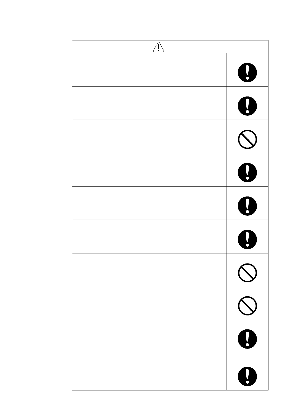
About the pictograms
This symbol indicates the item for which caution must be exercised.
The pictogram shows the item to which attention must be paid.
This symbol indicates the prohibited action.
The prohibited item or action is shown in the illustration or near the symbol.
This symbol indicates the action that must be taken, or the instruction.
The instruction is shown in the illustration or near the symbol.
After the repair work is complete, be sure to conduct a test operation to ensure that the
equipment operates normally, and explain the cautions for operating the product to the
customer.
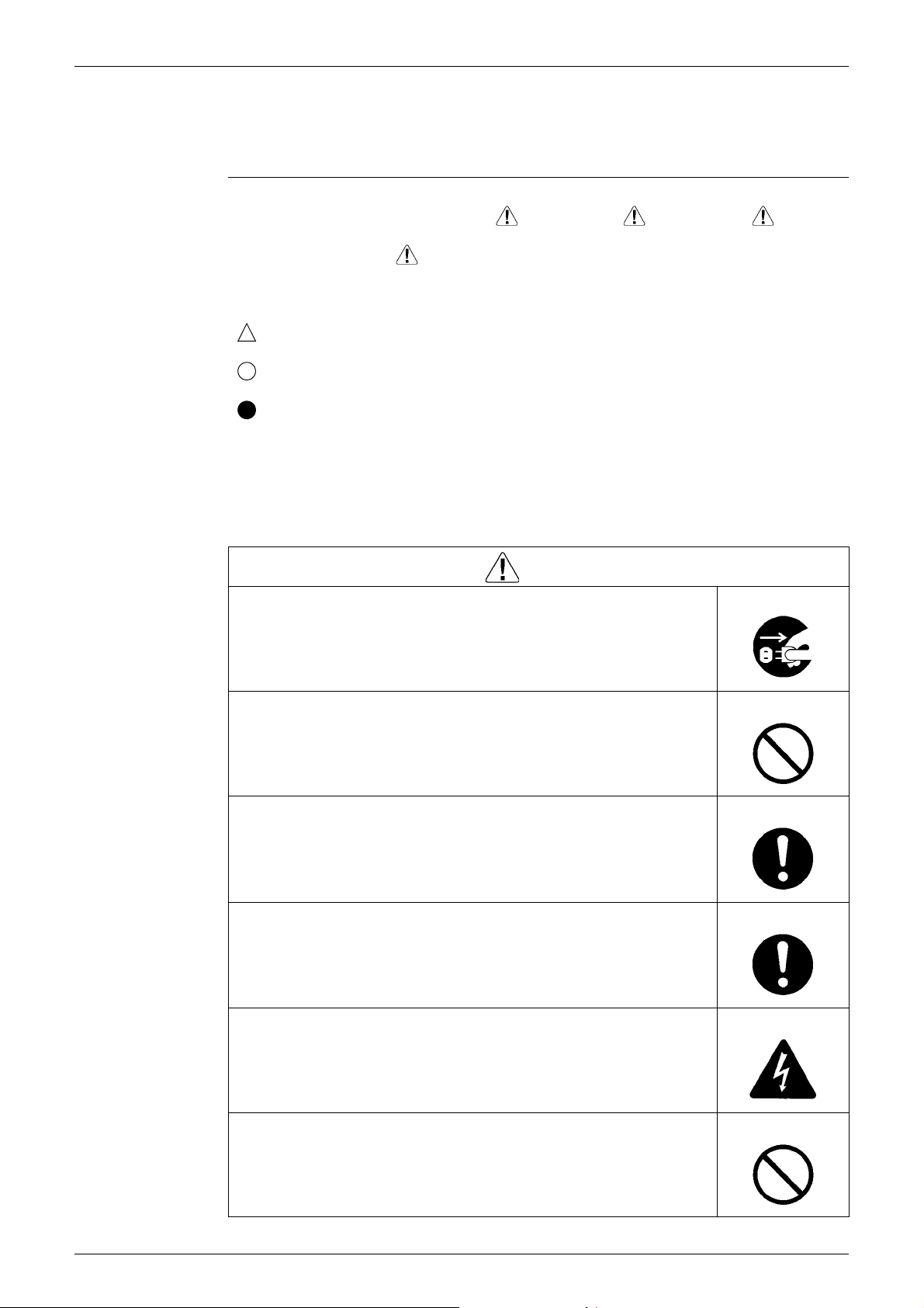
1.1.1 Cautions Regarding Safety of Workers
Be sure to disconnect the power cable plug from the plug socket before
disassembling the equipment for repair.
Working on the equipment that is connected to the power supply may cause an
electrical shook.
If it is necessary to supply power to the equipment to conduct the repair or
inspecting the circuits, do not touch any electrically charged sections of the
equipment.
If the refrigerant gas is discharged during the repair work, do not touch the
discharged refrigerant gas.
The refrigerant gas may cause frostbite.
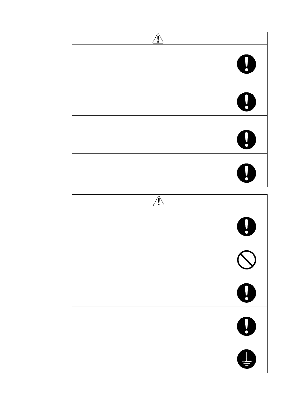
Warning
When disconnecting the suction or discharge pipe of the compressor at the
welded section, evacuate the refrigerant gas completely at a well-ventilated
place first.
If there is a gas remaining inside the compressor, the refrigerant gas or
refrigerating machine oil discharges when the pipe is disconnected, and it may
cause injury.
If the refrigerant gas leaks during the repair work, ventilate the area. The
refrigerant gas may generate toxic gases when it contacts flames.
The step-up capacitor supplies high-voltage electricity to the electrical
components of the outdoor unit.
Be sure to discharge the capacitor completely before conducting repair work.
A charged capacitor may cause an electrical shock.
Do not start or stop the air conditioner operation by plugging or unplugging the
power cable plug.
Plugging or unplugging the power cable plug to operate the equipment may
cause an electrical shock or fire.
iv
Introduction SiME281501E
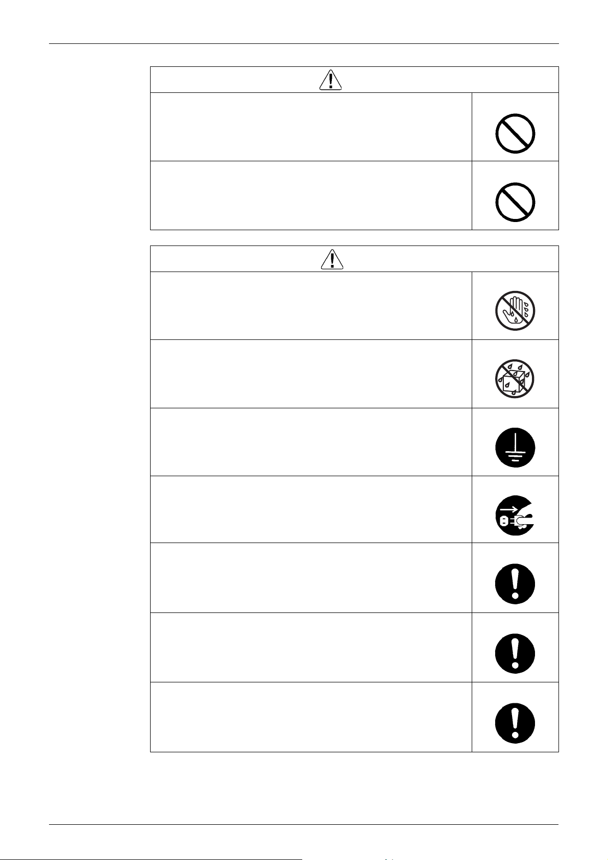
Warning
Be sure to wear a safety helmet, gloves, and a safety belt when working at a
high place (more than 2 m). Insufficient safety measures may cause a fall
accident.
In case of R410A refrigerant models, be sure to use pipes, flare nuts and tools
for the exclusive use of the R410A refrigerant.
The use of materials for R22 refrigerant models may cause a serious accident
such as a damage of refrigerant cycle as well as an equipment failure.
Caution
Do not repair the electrical components with wet hands.
Working on the equipment with wet hands may cause an electrical shock.
Do not clean the air conditioner by splashing water.
Washing the unit with water may cause an electrical shock.
Be sure to provide the grounding when repairing the equipment in a humid or
wet place, to avoid electrical shocks.
Be sure to turn OFF the power switch and unplug the power cable when
cleaning the equipment.
The internal fan rotates at a high speed, and cause injury.
Be sure to conduct repair work with appropriate tools.
The use of inappropriate tools may cause injury.
Be sure to check that the refrigerating cycle section has cooled down enough
before conducting repair work.
Working on the unit when the refrigerating cycle section is hot may cause
burns.
Use the welder in a well-ventilated place.
Using the welder in an enclosed room may cause oxygen deficiency.
v
SiME281501E Introduction
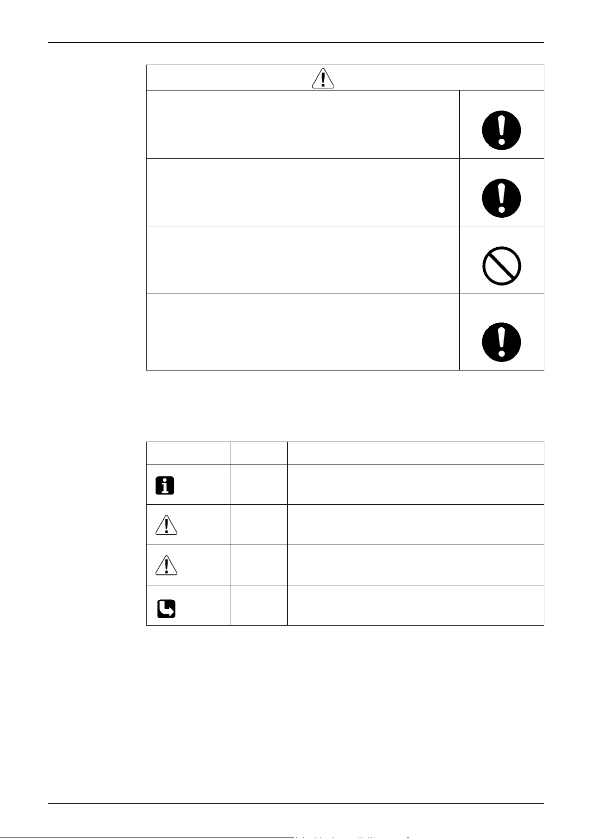
1.1.2 Cautions Regarding Safety of Users
Warning
Be sure to use parts listed in the service parts list of the applicable model and
appropriate tools to conduct repair work. Never attempt to modify the
equipment.
The use of inappropriate parts or tools may cause an electrical shock,
excessive heat generation or fire.
If the power cable and lead wires have scratches or deteriorated, be sure to
replace them.
Damaged cable and wires may cause an electrical shock, excessive heat
generation or fire.
Do not use a joined power cable or extension cable, or share the same power
outlet with other electrical appliances, since it may cause an electrical shock,
excessive heat generation or fire.
Be sure to use an exclusive power circuit for the equipment, and follow the local
technical standards related to the electrical equipment, the internal wiring
regulations, and the instruction manual for installation when conducting
electrical work.
Insufficient power circuit capacity and improper electrical work may cause an
electrical shock or fire.
Be sure to use the specified cable for wiring between the indoor and outdoor
units. Make the connections securely and route the cable properly so that there
is no force pulling the cable at the connection terminals.
Improper connections may cause excessive heat generation or fire.
When wiring between the indoor and outdoor units, make sure that the terminal
cover does not lift off or dismount because of the cable.
If the cover is not mounted properly, the terminal connection section may cause
an electrical shock, excessive heat generation or fire.
Do not damage or modify the power cable.
Damaged or modified power cable may cause an electrical shock or fire.
Placing heavy items on the power cable, and heating or pulling the power cable
may damage the cable.
Do not mix air or gas other than the specified refrigerant (R410A / R22) in the
refrigerant system.
If air enters the refrigerating system, an excessively high pressure results,
causing equipment damage and injury.
If the refrigerant gas leaks, be sure to locate the leaking point and repair it
before charging the refrigerant. After charging refrigerant, make sure that there
is no refrigerant leak.
If the leaking point cannot be located and the repair work must be stopped, be
sure to perform pump down and close the service valve, to prevent the
refrigerant gas from leaking into the room. The refrigerant gas itself is
harmless, but it may generate toxic gases when it contacts flames, such as fan
and other heaters, stoves and ranges.
When relocating the equipment, make sure that the new installation site has
sufficient strength to withstand the weight of the equipment.
If the installation site does not have sufficient strength and if the installation
work is not conducted securely, the equipment may fall and cause injury.
vi
Introduction SiME281501E
Warning
Check to make sure that the power cable plug is not dirty or loose, then insert
the plug into a power outlet securely.
If the plug has dust or loose connection, it may cause an electrical shock or fire.
Be sure to install the product correctly by using the provided standard
installation frame.
Incorrect use of the installation frame and improper installation may cause the
equipment to fall, resulting in injury.
Be sure to install the product securely in the installation frame mounted on the
window frame.
If the unit is not securely mounted, it may fall and cause injury.
When replacing the coin battery in the remote controller, be sure to disposed
of the old battery to prevent children from swallowing it.
If a child swallows the coin battery, see a doctor immediately.
Caution
Installation of a leakage breaker is necessary in some cases depending on the
conditions of the installation site, to prevent electrical shocks.
For unitary type
only
For unitary type
only
Do not install the equipment in a place where there is a possibility of
combustible gas leaks.
If the combustible gas leaks and remains around the unit, it may cause a fire.
Check to see if the parts and wires are mounted and connected properly, and
if the connections at the soldered or crimped terminals are secure.
Improper installation and connections may cause excessive heat generation,
fire or an electrical shock.
If the installation platform or frame has corroded, replace it.
Corroded installation platform or frame may cause the unit to fall, resulting in
injury.
Check the grounding, and repair it if the equipment is not properly grounded.
Improper grounding may cause an electrical shock.
vii
SiME281501E Introduction
Caution
Be sure to measure the insulation resistance after the repair, and make sure
that the resistance is 1 M or higher.
Defective insulation may cause an electrical shock.
Be sure to check the drainage of the indoor unit after the repair.
Defective drainage may cause the water to enter the room and wet the furniture
and floor.
Do not tilt the unit when removing it.
The water inside the unit may spill and wet the furniture and floor.
Be sure to install the packing and seal on the installation frame properly.
If the packing and seal are not installed properly, water may enter the room and
wet the furniture and floor.
1.2 Used Icons
Icons are used to attract the attention of the reader to specific information. The meaning of each
icon is described in the table below:
Icon Type of
Note:
Caution
Warning
For unitary type
only
Description
Information
Note A “note” provides information that is not indispensable, but may
nevertheless be valuable to the reader, such as tips and tricks.
Caution A “caution” is used when there is danger that the reader, through
incorrect manipulation, may damage equipment, loose data, get
an unexpected result or has to restart (part of) a procedure.
Warning A “warning” is used when there is danger of personal injury.
Reference A “reference” guides the reader to other places in this binder or
in this manual, where he/she will find additional information on a
specific topic.
viii

SiME281501E
Part 1
General Information
1. Model Name of Indoor / Outdoor Units ...................................................2
2. External Appearance...............................................................................3
1 General Information
SiME281501E Model Name of Indoor / Outdoor Units
1. Model Name of Indoor / Outdoor Units
Model series Indoor unit Outdoor unit Power supply intake
FCQ20EVA RZQ20LVA
Ceiling Mounted
Cassette Type
(Round Flow)
Duct Connection
Middle and High Static
Pressure Type
FCQ24EVA RZQ24LVA
FCQ36EVA RZQ36LVA
FCQ45EVA RZQ45LVA
FCQ36EVA RZQ36LVA
FCQ45EVA RZQ45LVA
FCQ36EVA RZQ36LVA
FCQ45EVA RZQ45LVA
FBQ20EVA RZQ20LVA
FBQ24EVA RZQ24LVA
FBQ36EVA RZQ36LVA
FBQ45EVA RZQ45LVA
FBQ36EVA RZQ36LVA
FBQ45EVA RZQ45LVA
FBQ45EVA RZQ45MYL
FBQ48EVA RZQ48MYL
Outdoor unit: 1 phase, 220V, 60Hz
Outdoor unit: 3 phase, 220V, 60Hz
Outdoor unit: 3 phase, 380V, 60Hz
Indoor unit: 1 phase, 220V, 60Hz
Outdoor unit: 1 phase, 220V, 60Hz
Indoor unit: 1 phase, 220V, 60Hz
Outdoor unit: 3 phase, 220V, 60Hz
Indoor unit: 1 phase, 220V, 60Hz
Outdoor unit: 3 phase, 380V, 60Hz
Note: : New model or changed model
General Information 2
External Appearance SiME281501E
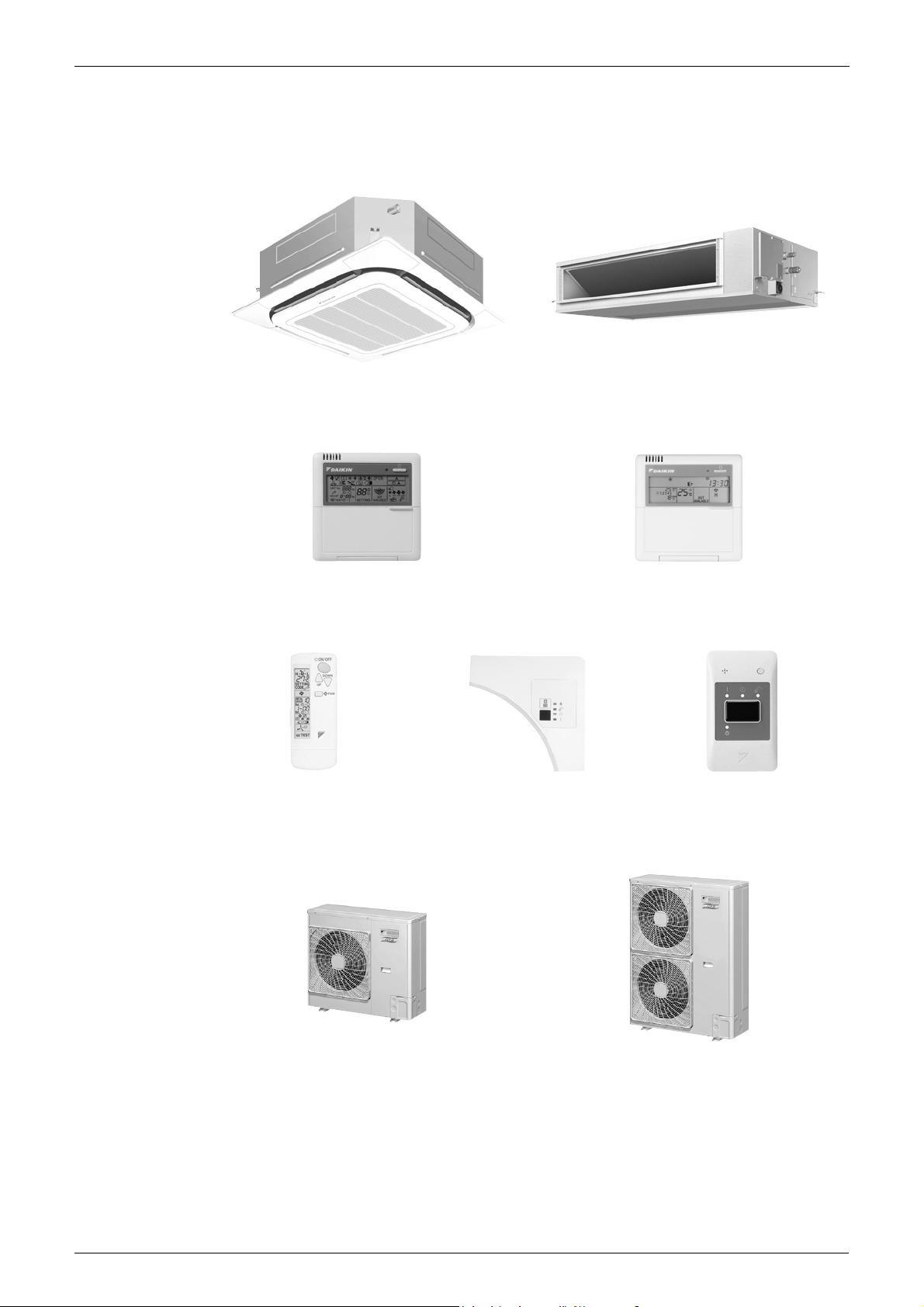
2. External Appearance
Indoor unit
FCQ FBQ-DA
Wired
remote controller
Wireless
remote controller
Outdoor unit
BRC1C61 BRC1D61
BRC7F632F (for FCQ)
BRC4C62 (for FBQ-DA)
Signal receiver unit
(for FCQ)
Signal receiver unit
(for FBQ-DA)
RZQ20LVA
RZQ24LVA
3 General Information
RZQ36LVA
RZQ45LVA
RZQ45MYL
RZQ48MYL

SiME281501E
Part 2
Functions
1. Functions.................................................................................................5
Functions 4
Functions SiME281501E
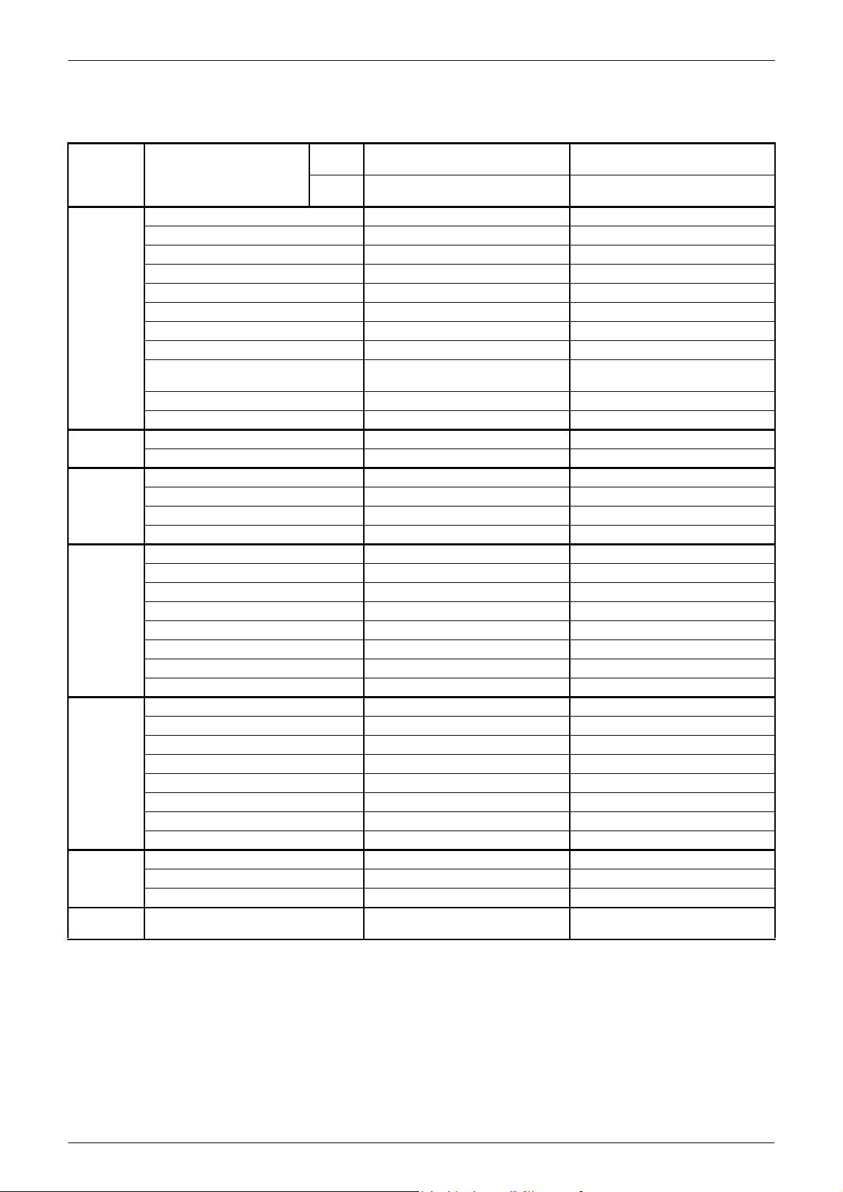
1. Functions
Indoor
Items Features
Comfort Auto swing —
Swing pattern selection —
Draft prevention function (heating) —
Switchable fan speed (2 step) (2 step)
Auto airflow rate — —
High fan speed mode — —
Program “Dry”
High ceiling application —
Two selectable temperature-sensors
(1)
Hot start (after defrost)
Year-round cooling applicable
Remote
controller
Cleanliness Anti-bacterial air filter (4)
Work &
servicing
Control
features
Options High-efficiency filter
Others Anti corrosion treated heat exchanger
Weekly schedule timer (3)
On/Off timer (5)
Mould-proof air filter — —
Silver ion anti-bacterial drain pan
Mould-proof drain pan — —
Drain pump mechanism —
Pre-charged for up to 30 m (2)
Long-life filter (4)
Filter sign
Ceiling soiling prevention —
Low gas pressure detection (2)
Emergency operation
Self-diagnosis function
Auto-restart
Auto cooling/heating changeover
Control by 2 remote controllers
Group control by 1 remote controller
External command control
Centralized remote control
Interlock control
DIII-NET communication standard
Ultra long-life filter —
Fresh air intake kit —
(2)
unit
Outdoor
unit
FCQ20-45EVA FBQ20-48EVA
RZQ20-45LVA
RZQ45-48MYL
RZQ20-45LVA
RZQ45-48MYL
Note: : Functions exist.
— : No functions
1 : Applicable when wired remote controller is used
2 : For the outdoor units
3 : Applicable when BRC1D61 is used
4 : Option
5 : Applicable when BRC1C61 is used
5 Functions

SiME281501E
Part 3
Remote Controller
1. Wired Remote Controller.........................................................................7
1.1 Applicable Models ....................................................................................7
1.2 Names and Functions ..............................................................................8
1.3 MAIN/SUB Setting when Using 2 Remote Controllers ...........................11
1.4 Centralized Control Group No. Setting...................................................12
2. Wireless Remote Controller ..................................................................13
2.1 Applicable Models ..................................................................................13
2.2 Names and Functions ............................................................................13
2.3 Address and MAIN/SUB Setting.............................................................15
3. Service Mode ........................................................................................17
3.1 BRC1C61/BRC1D61 ..............................................................................17
Remote Controller 6
Wired Remote Controller SiME281501E
1. Wired Remote Controller
1.1 Applicable Models
Model Series FCQ-EV FBQ-EV
Remote Controller Heat Pump BRC1C61
Wired Remote Controller with Weekly
Schedule Timer
BRC1D61
7 Remote Controller
SiME281501E Wired Remote Controller
hr
hr
C
C: 3PA59583-16Z
2
10
11
3
1
4
5
6
7
8
14
15
16
17
18
19
20
21
22
12
9
13
1
2
3
4
5
6
7
8
9
10
11
12
13
14
15
16
17
18
19
20
21
22
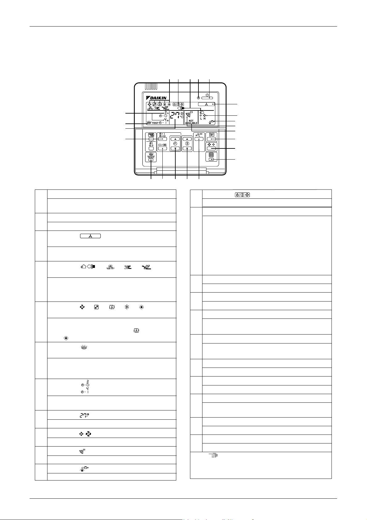
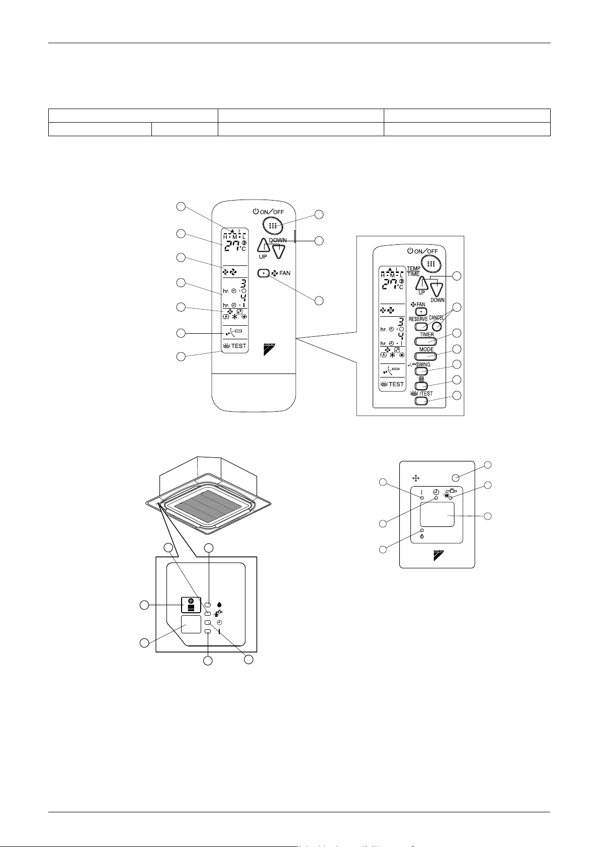
ON/OFF BUTTON
Press the button and the system will start.
Press the button again and the system will stop.
OPERATION LAMP (RED)
The lamp lights up during operation.
DISPLAY “ ” (UNDER CENTRALIZED
CONTROL)
When this display shows, the system is UNDER
CENTRALIZED CONTROL.
DISPLAY “ ” “ ” “ ” “ ”
(VENTILATION/AIR CLEANING)
This display shows that the total heat exchange
and the air cleaning unit are in operation
(These are optional accessories).
DISPLAY “ ” “ ” “ ” “ ” “ ”
(OPERATION MODE)
This display shows the current OPERATION
MODE. For cooling only type, “ ” (Auto)
and “ ” (Heating) are not installed.
DISPLAY “
TEST” (INSPECTION/TEST
OPERATION)
When the INSPECTION/TEST OPERATION
BUTTON is pressed, the display shows the
system mode is in.
DISPLAY “ ” (PROGRAMMED TIME)
This display shows the PROGRAMMED TIME
of the system start or stop.
This display shows the set temperature.
DISPLAY “ ” (FAN SPEED)
DISPLAY “ ” (SET TEMPERATURE)
This display shows the set fan speed.
DISPLAY “ ” (AIRFLOW FLAP)
DISPLAY “ ”(TIME TO CLEAN AIR FILTER)
If that particular function is not available, pressing
the button may display the words “NOT
AVAILABLE” for a few seconds.
When running multiple units simultaneously the
“NOT AVAILABLE” message will only be appear
if none of the indoor units is equipped with the
function. If even one unit is equipped with the
function, the display will not appear.
DISPLAY
“ ” (DEFROST)
NON-FUNCTIONING DISPLAY
TIMER MODE START/STOP BUTTON
TIMER ON/OFF BUTTON
INSPECTION/TEST OPERATION BUTTON
This button is used only by qualified service
persons for maintenance purposes.
PROGRAMMING TIME BUTTON
Use this button for programming “START and/or
STOP” time.
TEMPERATURE SETTING BUTTON
Use this button for SETTING TEMPERATURE.
FILTER SIGN RESET BUTTON
FAN SPEED CONTROL BUTTON
Press this button to select the fan speed,
HIGH or LOW, of your choice.
OPERATION MODE SELECTOR BUTTON
Press this button to select OPERATION MODE.
AIRFLOW DIRECTION ADJUST BUTTON
NOTE
• For the sake of explanation, all indications are shown
on the display in the above figure contrary to actual
running situations.
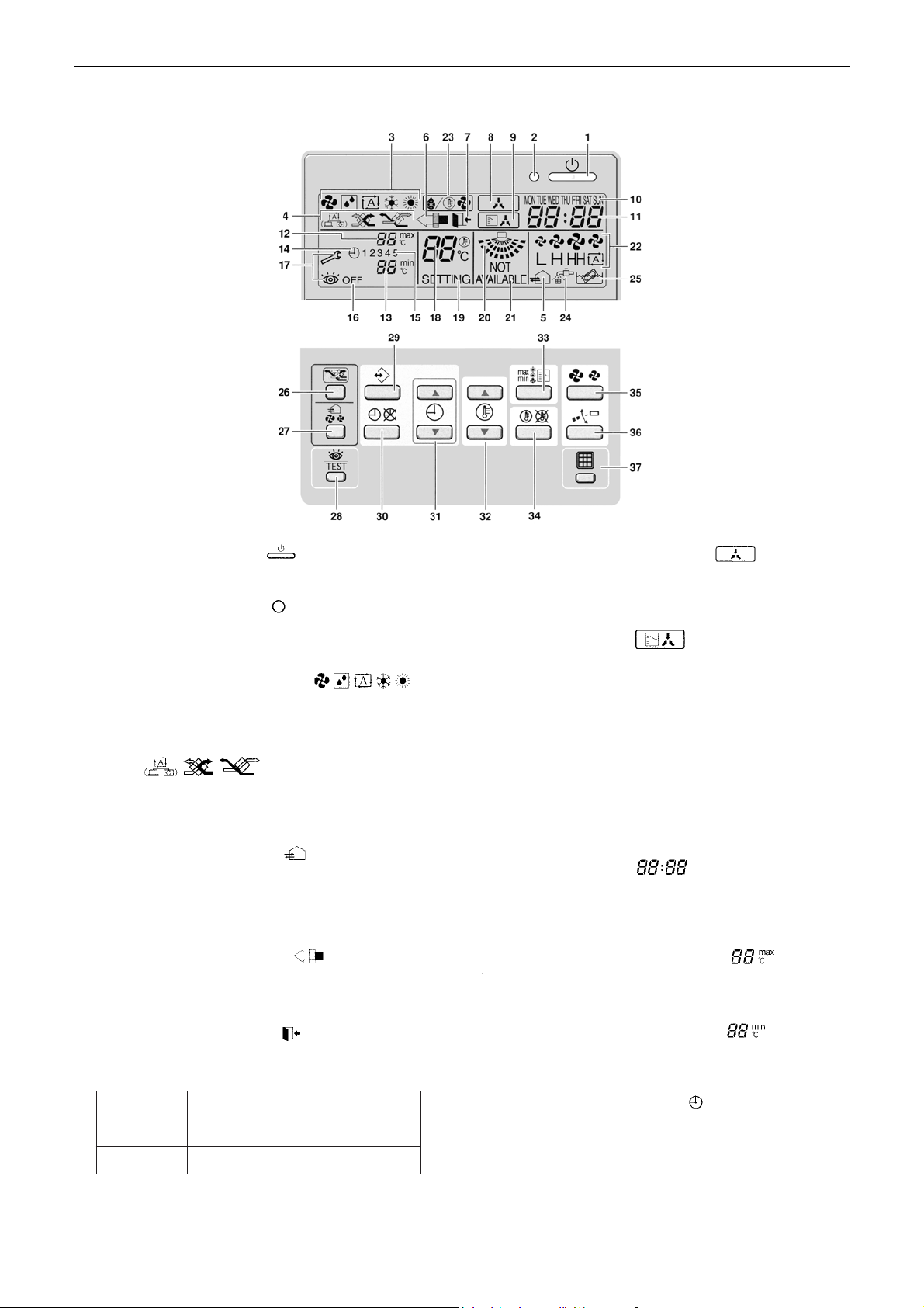
1.2 Names and Functions
1.2.1 BRC1C61
Remote Controller 8
Wired Remote Controller SiME281501E
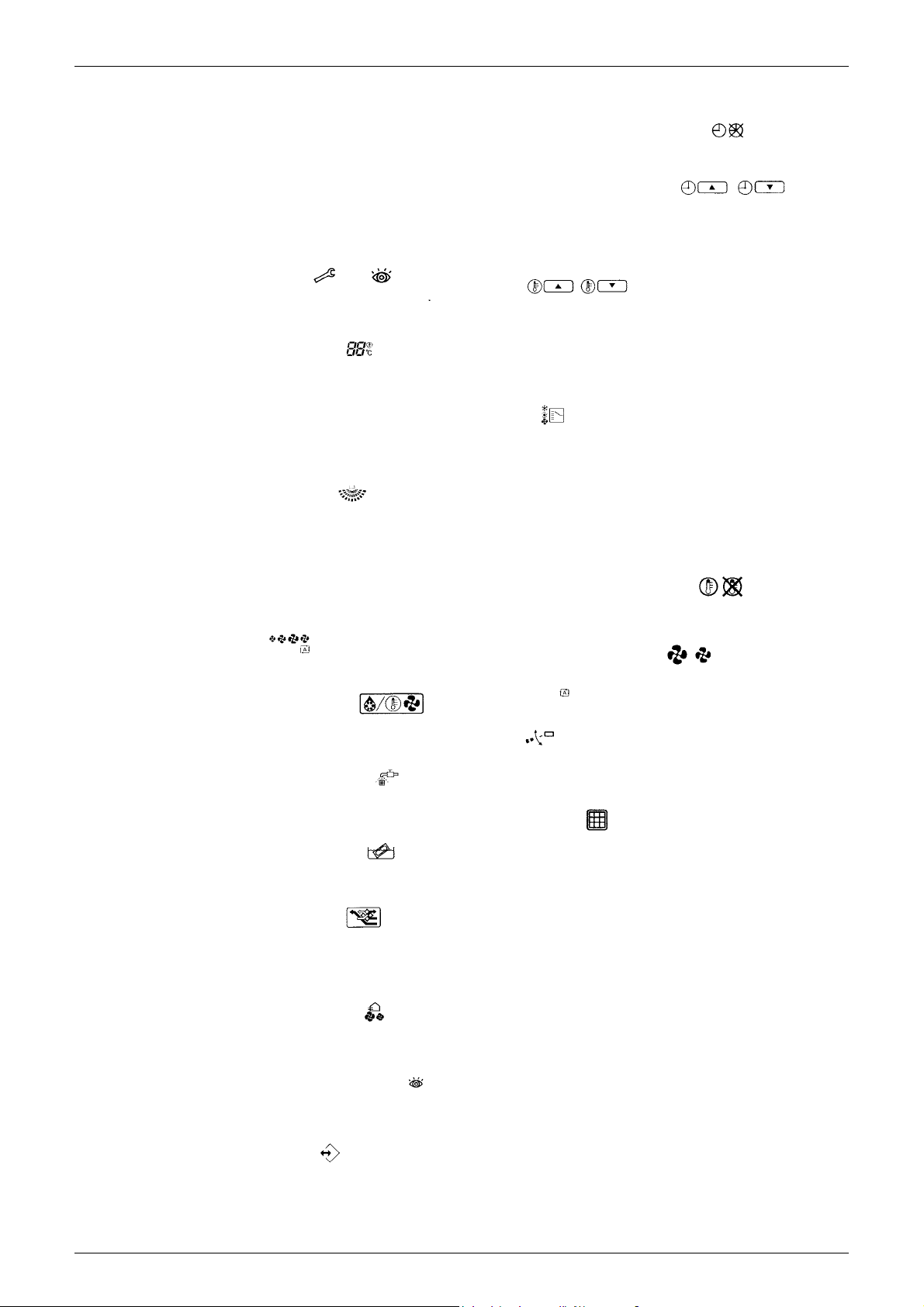
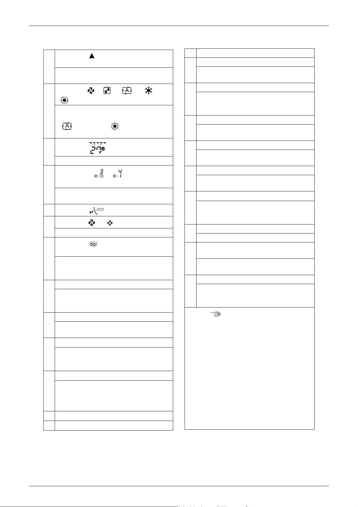
1 ON/OFF BUTTON
Press the ON/OFF button to start or stop the system.
2 OPERATION LAMP
The operation lamp lights up during operation or
blinks if an error occurs.
3 OPERATION MODE ICON
These icons indicate the current operation mode
(FAN, DRY, AUTOMATIC, COOLING, HEATING).
4 VENTILATION MODE ICON
These icons indicate the current ventilation mode
(Heat Reclaim Ventilator only) (AUTOMATIC, HEAT
EXCHANGE, BYPASS).
5 VENTILATION ICON
The ventilation icon appears when the ventilation is
adjusted with the ventilation amount button (Heat
Reclaim Ventilator only). Simultaneously, the ventilation
amount is indicated by the fan speed icon (see 22).
6 AIR CLEANING ICON
This icon indicates that the air cleaning unit (option) is
operational.
7 LEAVE HOME ICON
The leave home icon shows the status of the leave
home function.
ON
FLASHING
OFF
Leave home is enabled
Leave home is active
Leave home is disabled
8 EXTERNAL CONTROL ICON
This icon indicates that another controller with higher
priority is controlling or disabling your installation.
9 CHANGE-OVER UNDER CENTRALIZED
CONTROL ICON
This icon indicates that the change-over of the
installation is under centralized control assigned to
another indoor unit or optional cool/heat selector
connected to the outdoor unit (= main remote
controller).
10 DAY OF THE WEEK INDICATOR
MON TUE WED THU FRI SAT SUN
The day of the week indicator shows the current week
day (or the set day when reading or programming the
schedule timer).
11 CLOCK DISPLAY
The clock display indicates the current time (or the
action time when reading or programming the
schedule timer).
12 MAXIMUM SET TEMPERATURE
The maximum set temperature indicates the
maximum set temperature when in limit operation.
13 MINIMUM SET TEMPERATURE
The minimum set temperature indicates the minimum
set temperature when in limit operation.
14 SCHEDULE TIMER ICON
This icon indicates that the schedule timer is enabled.
1.2.2 BRC1D61
9 Remote Controller
C: 3P107422-3D
SiME281501E Wired Remote Controller
15 ACTION ICONS 1 2 3 4 5
These icons indicate the actions for each day of the
schedule timer.
16 OFF ICON
OFF
This icon indicates that the OFF action is selected
when programming the schedule timer.
17 INSPECTION REQUIRED and
These icons indicate that inspection is required.
Consult your installer.
18 SET TEMPERATURE DISPLAY
This indicates the current set temperature of the
installation (not shown in LIMIT operation or in FAN or
DRY mode).
19 SETTING
SETTING
Not used, for service purposes only.
20 AIRFLOW DIRECTION ICON
This icon indicates the airflow direction (only for
installations with motorised airflow flaps).
21 NOT AVAILABLE
is displayed whenever a non-installed option
is addressed or a function is not available.
NOT
AVAILABLE
NOT
AVAILABLE
22 FAN SPEED ICON
This icon indicates the set fan speed.
23
DEFROST/HOTSTART MODE ICON
This icon indicates that the defrost/hotstart mode is
active.
24
AIR FILTER CLEANING TIME ICON
This icon indicates the air filter must be cleaned.
Refer to the manual of the indoor unit.
25 ELEMENT CLEANING TIME ICON
This icon indicates the element must be cleaned
(Heat Reclaim Ventilator only).
26
VENTILATION MODE BUTTON
The ventilation mode button operates the Heat
Reclaim Ventilator; refer to the Heat Reclaim
Ventilator manual for more details.
27 V
ENTILATION AMOUNT BUTTON
This button sets the ventilation amount; refer to the
Heat Reclaim Ventilator manual for more details.
28
INSPECTION/TEST OPERATION BUTTON
Not used, for service purposes only.
TEST
29 PROGRAMMING BUTTON
This button is a multi-purpose button.
Depending on the previous manipulations of the user,
the programming button can have various functions.
30
SCHEDULE TIMER BUTTON
This button enables or disables the schedule timer.
31 TIME ADJUST BUTTON
These buttons are used to adjust the clock or, when in
programming mode, to adjust the programmed action
time. Both buttons have an auto-repeat function.
32 TEMPERATURE ADJUST BUTTONS
These buttons are used to adjust the current setpoint
or, when in programming mode, to adjust the
programmed setpoint temperature (step = 1˚C). Both
buttons are also used to adjust the day of the week.
33 OPERATION CHANGE/MIN-MAX BUTTON
This button is a multi-purpose button. Depending on
the previous manipulations of the user, it can have
following functions.
1 select the operation mode of the installation
(FAN, DRY, AUTOMATIC, COOLING, HEATING)
2 toggle between minimum temperature and
maximum temperature when in limit operation
34 SETPOINT/LIMIT BUTTON
This button toggles between setpoint, limit operation
or
OFF (programming mode only).
35
FAN SPEED BUTTON
This button toggles between L (Low), H (High), HH
(very High), (Automatic).
36 AIRFLOW DIRECTION ADJUST BUTTON
This button enables to adjust the airflow direction.
37 AIR FILTER CLEANING TIME ICON RESET
BUTTON
This button is used to reset the air filter cleaning time
icon.
max
min
L H
HH
Remote Controller 10
3P107422-3D
Wired Remote Controller SiME281501E
Upper part of the
remote controller
Lower part of the
remote controller
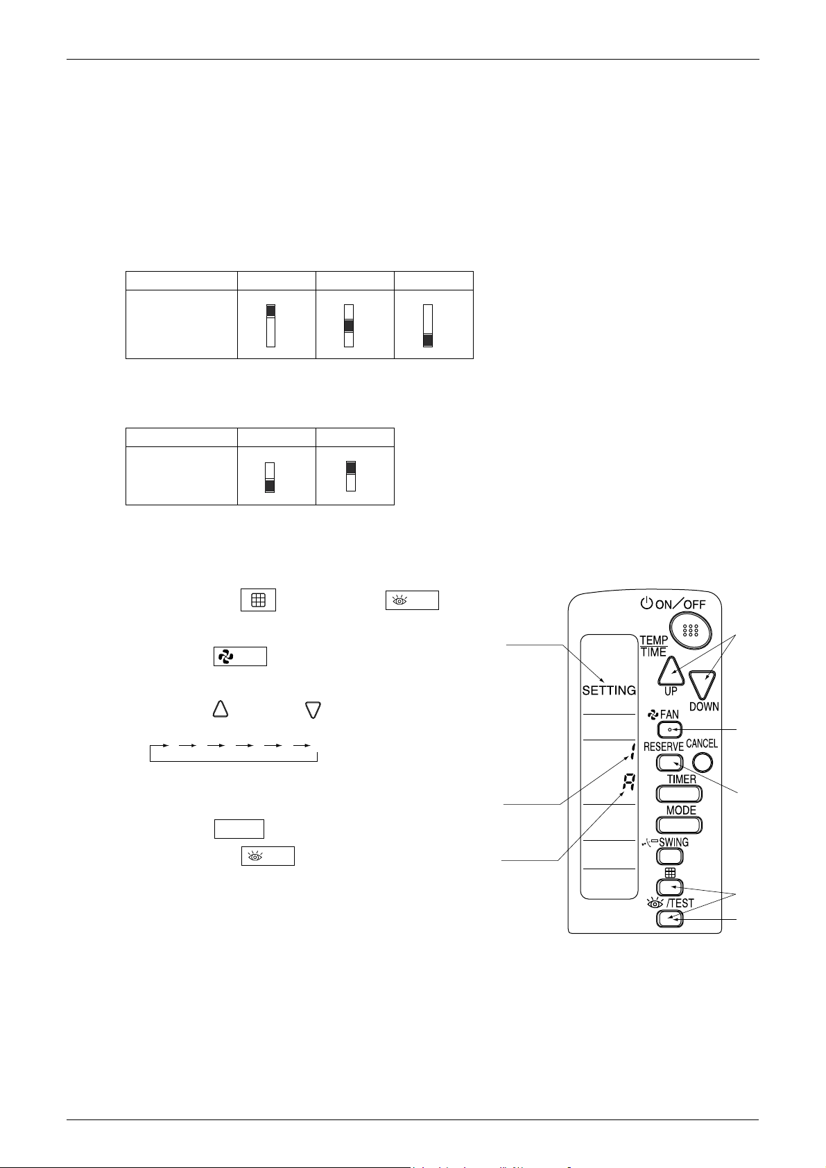
S
M
S
M
The switch is set to MAIN (factory
setting)
Set the switch to SUB.
1.3 MAIN/SUB Setting when Using 2 Remote Controllers
Situation
The MAIN/SUB setting is necessary when 1 indoor unit is controlled by 2 remote controllers. When you use 2
remote controllers (control panel and separate remote controller), set one to MAIN and the other to SUB.
Setting
The remote controllers are set at factory to MAIN, so you only have to change 1 remote controller from MAIN
to SUB. To change a remote controller from MAIN to SUB, proceed as follows:
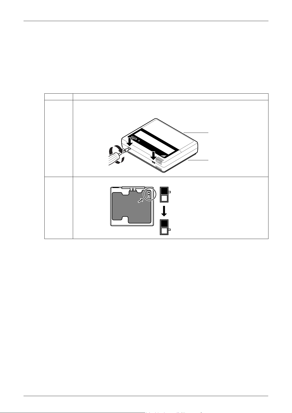
1.3.1 BRC1C61/BRC1D61
Step Action
1 Insert a flathead screwdriver into the recess between the upper and lower part of the remote
controller, as shown in the illustration below. Gently pry off the upper part of the controller, working
from the 2 possible positions.
2 Turn the MAIN/SUB changeover switch on the PCB to “S”.
11 Remote Controller
SiME281501E Wired Remote Controller
TEST
TEST
4
1,5
3
2
Group No.
Mode No.
Field Setting
Mode
4
1,5
3
2
Group No.
Mode No.
Field Setting
Mode
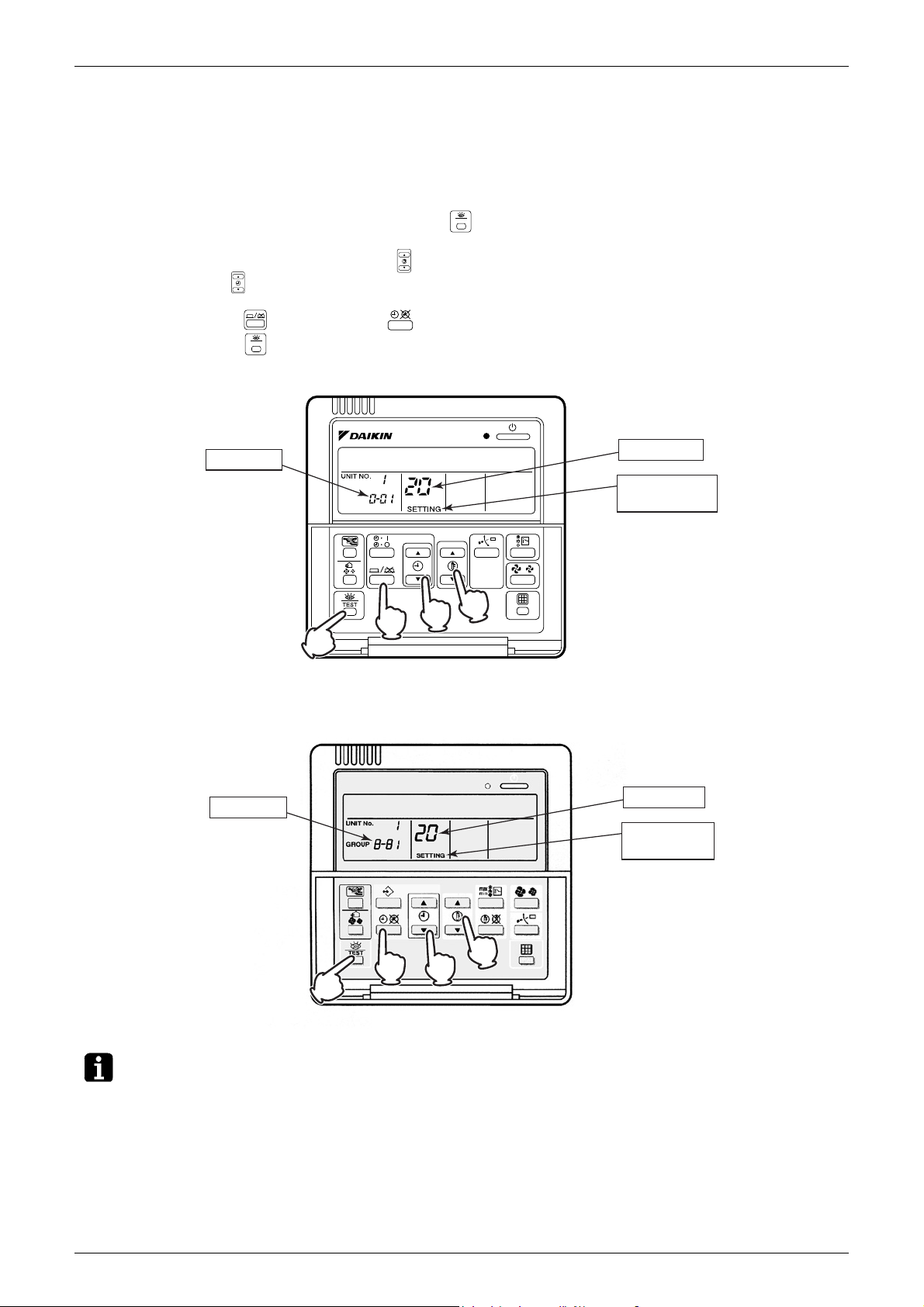
1.4 Centralized Control Group No. Setting
1.4.1 BRC1C61/BRC1D61
In order to conduct the centralized remote control using the central remote controller and the unified ON/OFF
controller, Group No. settings should be made by group using the operating remote controller.
Make Group No. settings for centralized remote control using the operating remote controller.
1. While in normal mode, press and hold the “ ” button for 4 seconds or more to set the system to "Field
Setting Mode".
2. Select the Mode No. “00” with the “ ” button.
3. Use the “ ” button to select the Group No. for each group.
(Group numbers increase in the order of 1-00, 1-01, ... 1-15, 2-00, ... 4-15.)
4. Press the “ ” button or the “ ” button to set the selected group No.
5. Press the “ ” button to return to the Normal Mode.
BRC1C61
BRC1D61
Note:
For setting Group No. of Heat Reclaim Ventilator and wiring adaptor for other air conditioners, etc., refer to
the installation manual attached.
NOTICE
Enter the Group No. and installation place of the indoor unit into the attached installation table. Be sure to
keep the installation table with the operation manual for maintenance.
Remote Controller 12
Wireless Remote Controller SiME281501E
1-1
1-2
8
10
13
11
12
15
14
16
17
9
1
3
4
6
2
5
7
19
23
22
18
20
21
20
21
23
18
22
19
2. Wireless Remote Controller
2.1 Applicable Models
Model Series FCQ FBQ-DA
Remote Controller Heat Pump BRC7F632F BRC4C62
2.2 Names and Functions
3P107422-11J
Receiver
FCQ-K/KA
FBQ-DA (separate type)
3P107422-21S
13 Remote Controller
3P107422-11J
SiME281501E Wireless Remote Controller
MHL
C
hr.
hr.
•
•
•
•
14
15
16
17
18
19
20
21
22
23
1
2
3
4
5
6
7
8
9
10
11
12
13
This display shows the current
OPERATION MODE. For cooling only type,
“ ” (Auto) and “ ” (Heating) are not
installed.
DISPLAY “ ” (SIGNAL
TRANSMISSION)
This lights up when a signal is being
transmitted.
DISPLAY “ ”
(PROGRAMMED TIME)
DISPLAY “ ”
(SET TEMPERATURE)
This display shows the set temperature.
This display shows PROGRAMMED TIME
of the system start or stop.
DISPLAY “ ” (AIRFLOW FLAP)
DISPLAY “ ” “ ” (FAN SPEED)
The display shows the set fan speed.
DISPLAY “ TEST ”
(INSPECTION/TEST OPERATION)
When the INSPECTION/TEST
OPERATION BUTTON is pressed, the
display shows the system mode is in.
ON/OFF BUTTON
Press the button and the system will start.
Press the button again and the system will
stop.
FAN SPEED CONTROL BUTTON
Press this button to select the fan speed,
HIGH or LOW, of your choice.
TEMPERATURE SETTING BUTTON
Use this button for SETTING
TEMPERATURE (Operates with the front
cover of the remote controller closed.)
PROGRAMMING TIMER BUTTON
Use this button for programming “START
and/or STOP” time. (Operates with the
front cover of the remote controller
opened.)
TIMER MODE START/STOP BUTTON
TIMER RESERVE/CANCEL BUTTON
AIRFLOW DIRECTION ADJUST BUTTON
OPERATION MODE SELECTOR BUTTON
Press this button to select OPERATION
MODE.
FILTER SIGN RESET BUTTON
Refer to the section of MAINTENANCE in
the operation manual attached to the
indoor unit.
INSPECTION/TEST OPERATION BUTTON
This button is used only by qualified service
persons for maintenance purposes.
EMERGENCY OPERATION SWITCH
This switch is readily used if the remote
controller does not work.
RECEIVER
This receives the signals from the remote
controller.
OPERATING INDICATOR LAMP (Red)
This lamp stays lit while the air
conditioner runs. It blinks when the unit
is in trouble.
TIMER INDICATOR LAMP (Green)
This lamp stays lit while the timer is set.
AIR FILTER CLEANING TIME
INDICATOR LAMP (Red)
Lights up when it is time to clean the air
filter.
DEFROST LAMP (Orange)
Lights up when the defrosting operation
has started. (For cooling only type this
lamp does not turn ON.)
For the sake of explanation, all indications
are shown on the display in Figure 1 contrary
to actual running situations.
Fig. 1-2 shows the remote controller with the
front cover opened.
If the air filter cleaning time indicator lamp
lights up, clean the air filter as explained in
the operation manual provided with the
indoor unit.
After cleaning and reinstalling the air filter
press the filter sign reset button on the
remote controller. The air filter cleaning time
indicator lamp on the receiver will go out.
The Defrost Lamp will blink when power is
turned ON. This is not an error.
DISPLAY “ ” “ ” “ ” “ ”
“ ” (OPERATION MODE)
NOTES
Remote Controller 14
C: 3P107422-11J
Wireless Remote Controller SiME281501E
1 2 3
1 2 3
1 2 3
S
M
S
M
Mode
Address
Multiple
setting
3
2
4
1
5
/TEST
FAN
UP
DOWN
123456
RESERVE
/TEST
2.3 Address and MAIN/SUB Setting
Introduction
To set the wireless remote controller, you have to set the address for:
The receiver of the wireless remote controller
The wireless remote controller.
Setting the Address for the Receiver
The address for the receiver of the wireless remote controller is factory setting to 1. To change this setting,
proceed as follows:
Set the wireless address switch (SS2) on the PCB according to the table below.
Unit No. No. 1 No. 2 No. 3
Wireless address
switch (SS2)
When using both a wired and a wireless remote controller for 1 indoor unit, the wired controller should be set
to MAIN. Therefore, set the MAIN/SUB switch (SS1) of the receiver to SUB.
For FCQ, FBQ
MAIN/SUB MAIN SUB
MAIN/SUB
switch (SS1)
Setting the Address for the Wireless Remote Controller
The address for the wireless remote controller is factory setting to 1. To change this setting, proceed as
follows:
1. Hold down the “ ” button and the “ ”
button for at least 4 seconds to get the Field Setting mode.
(Indicated in the display area in the figure at right.)
2. Press the “ ” button and select a multiple setting
(A/b). Each time the button is pressed the display
switches between “A” and “b”.
3. Press the “ ” button or “ ” button to set the address.
Address can be set from 1 to 6, but set it to 1 ~ 3 and to
same address as the receiver. (The receiver does not
work with address 4 ~ 6.)
4. Press the “ ” button to enter the setting.
5. Hold down the “ ” button for at least 1 second to
quit the Field Setting mode and return to the normal
display.
15 Remote Controller
SiME281501E Wireless Remote Controller
Multiple Settings A/b
When the indoor unit is being operating by external control (central remote controller, etc.), it sometimes does
not respond to ON/OFF and temperature setting commands from this remote controller. Check what setting
the customer wants and make the multiple setting as shown below.
Remote controller FCQ FBQ
Multiple
setting
A: Standard All items displayed.
b: Multi
System
Remote controller
display
Operations remain
displayed shortly after
execution.
Movement when the operation is controlled
by the other air conditioners and equipment
When operation changeover, temperature
setting or the like is carried out from the
remote controller, the indoor unit rejects the
instruction.
(Signal receiving sound “peeh” or “pickpick-pick”)
As a result, a discrepancy between the
operation state of the indoor unit and the
indication of the remote controller display
occurs.
Since the indication of the remote controller
is turned OFF, no discrepancy such as
mentioned above occurs.
To control other air
conditions and units
Commands other than ON/
OFF and temperature
setting accepted.
(1 LONG BEEP or 3
SHORT BEEPS emitted)
All commands accepted (2 SHORT
BEEPS)
For other than
on left
Remote Controller 16
Service Mode SiME281501E
2
7
6
3
4
5
3
1
Unit No.
Second
Code No.
First
Code No.
Mode No.
Field
Setting
Mode
UNIT NO.
past error
code
CODE
SETTING
Error history
: Newest
: Oldest
1
3
∼
∗ "00" displayed for 4 and subsequent.
UNIT No.
Thermistor type
Temperature
SETTING
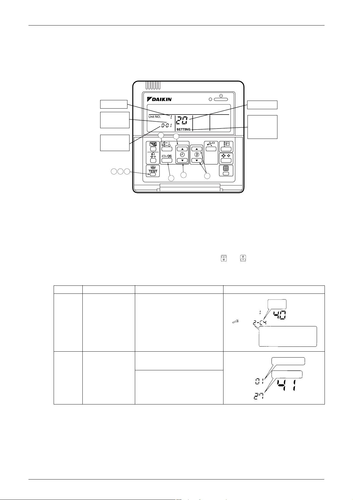
3. Service Mode
3.1 BRC1C61/BRC1D61
3.1.1 Display Service Data
1. Enter the field setting mode.
Press the INSPECTION/TEST button for 4 seconds or more.
2. Enter the service mode.
After having entered the field setting mode, press the INSPECTION/TEST button for 4 seconds or more.
3. Select the mode No.
Set the desired mode No. with the up/down temperature setting button.
4. Select the unit No.
Select the indoor unit No. set with the time mode START/STOP button.
5. Select the desired error history No. or thermistor data No. with “ ” or “ ” button.
6. Each data displays (Refer to the table below display)
7. Return to the normal operation mode.
Press the INSPECTION/TEST button once.
Mode No. Function Content and Operation Method Example of Remote Controller Display
40 Error History You can change the history with the
41 Thermistor Data
Display
programming time up-down button.
Select the display thermistor with
the programming time up-down
button
Display thermistor
00: Room temperature thermistor in
remote controller
01: Suction air thermistor
02: Heat exchanger thermistor
17 Remote Controller
SiME281501E Service Mode
2
6
5
3
4
5
3
1
Unit No.
Second
Code No.
First
Code No.
Mode No.
Field
Setting
Mode
Mode No.
Field Setting Mode
5
5
Second Code No.
First Code No.
3
1, 2, 6
SETTING
UNIT No.
UNIT No.
CODE
Fan
speed
1 : Low
3 : High
Airflow direction
SETTING
0: Upper
4: Lowest
UNIT No.
CODE
SETTING
Field setting No.
No. after change
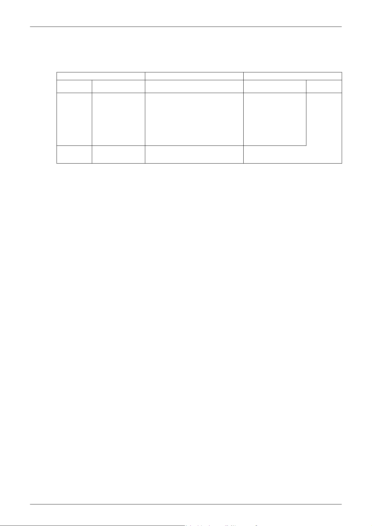
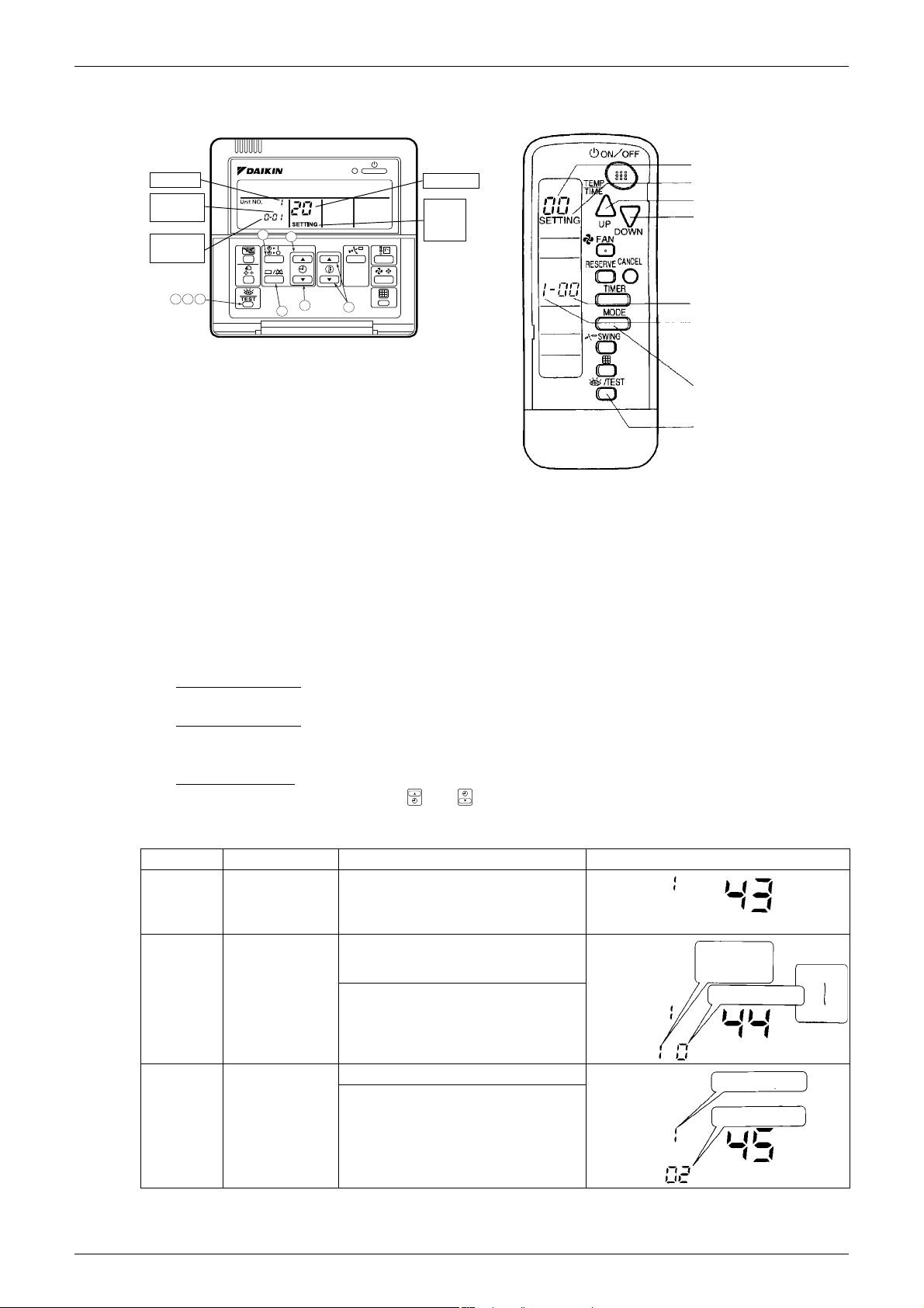
3.1.2 Service Setting
1. Enter the field setting mode.
Press the INSPECTION/TEST operation button for 4 seconds or more.
2. Enter the maintenance mode.
After having entered the field setting mode, press the INSPECTION/TEST operation button for a minimum
of 4 seconds.
3. Select the mode No.
Set the desired mode No. with the up/down temperature setting button.
4. Select the unit No.
Select the indoor unit No. set with the time mode START/STOP button.
5. Carry out the necessary settings for each mode. (Only mode 43 possible for wireless remote controller)
• In case of Mode 43
Press timer ON/OFF button to decide the forced Fan ON.
• In case of Mode 44
Set “Fan speed” with fan speed control button and “Airflow direction” with airflow direction adjusting
button, then press timer ON/OFF button to decide.
In case of Mode 45
•
Select the changed unit No. with “ ” or “ ” button, then press timer ON/OFF button to decide.
6. Return to the normal operation mode.
Press the INSPECTION/TEST operation button once.
Mode No. Function Content and Operation Method Example of Remote Controller Display
43 Forced Fan ON Turns the fan ON for each unit
individually.
44 Individual Setting Sets fan speed and airflow direction for
each unit individually when using group
control.
Settings are made using the “airflow
direction adjust” and “fan speed adjust”
buttons.
45 Unit No. Change Changes unit No.
Set the unit No. after changing with the
programming time up-down button.
Remote Controller 18

SiME281501E
Part 4
Function and Control
1. Functions of Main Components and Thermistors .................................20
2. Function Outline ....................................................................................23
2.1 Indoor Unit..............................................................................................23
3. Operation Flow Chart ............................................................................25
3.1 Cooling / Dry Operation..........................................................................25
3.2 Heating Operation ..................................................................................26
4. Function Details ....................................................................................27
4.1 Indoor Unit..............................................................................................27
4.2 Outdoor Unit ...........................................................................................32
19 Function and Control
SiME281501E Functions of Main Components and Thermistors
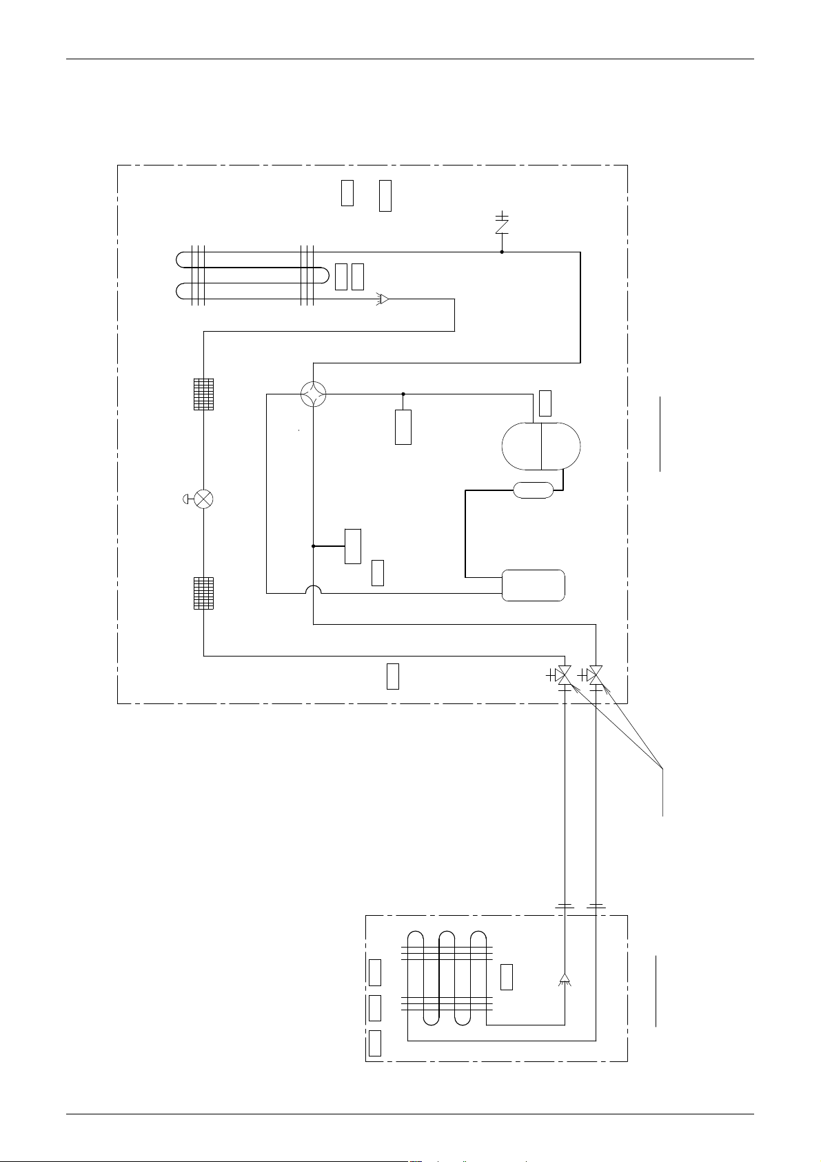
3D058951C
Indoor heat exchanger
R2T
R3T R5T
Indoor unit
R1T
Stop valve
(with service port 5/16'' flare)
Accumulator
(C) Four way valve
FilterFilter
S1NPH
S1PH
(A) Compressor
Outdoor unit
(B)
Electronic
expansion valve
Outdoor unit
heat exchanger
Pressure
sensor
(high/low)
Pressure
switch
(high)
Gauge port
(5/16'' flare)
R6T
R3T
R4T
R1T
∗
R10T
R5T
R2T
∗This thermistor is near the el. compo. box.
Compressor
accumulator
Field piping φ 9.5
C1220T-O
Field piping φ 15.9
C1220T-O
1. Functions of Main Components and Thermistors
FCQ20EVA / FBQ20EVA + RZQ20LVA
FCQ24EVA / FBQ24EVA + RZQ24LVA
Function and Control 20
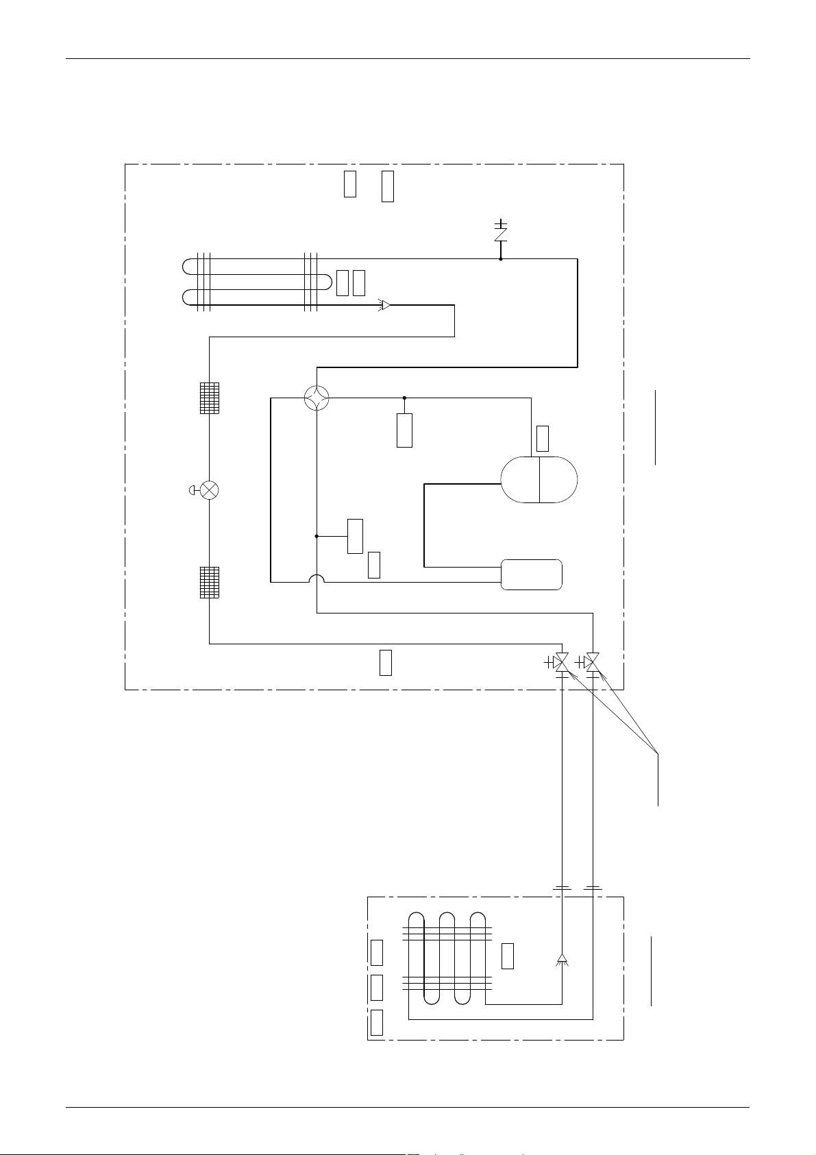
Functions of Main Components and Thermistors SiME281501E
3D060254C
Indoor heat exchanger
Accumulator
(C) Four way valve
FilterFilter
S1NPH
S1PH
(A) Compressor
Indoor unit
Outdoor unit
Stop valve
(with service port 5/16'' flare)
(B)
Electronic
expansion valve
Outdoor unit
heat exchanger
Pressure
sensor
(high/low)
Pressure
switch
(high)
Gauge port
(5/16'' flare)
R2T
R3T R5T
R1T
R6T
R3T
R2T
R4T
R1T
∗
R10T
R5T
∗This thermistor is near the el. compo. box.
Field piping φ 9.5
C1220T-O
Field piping φ 15.9
C1220T-O
FCQ36EVA / FBQ36EVA + RZQ36LVA
FCQ45EVA / FBQ45EVA + RZQ45LVA
FCQ45EVA / FBQ45EVA + RZQ45MYL
FCQ48EVA / RBQ48EVA + RZQ48MYL
21 Function and Control
 Loading...