

Page 1

INSTALLATION MANUAL
ﺐﻴﻛﺮﺘﻟﺍ ﻞﻴﻟﺩ
English
SPLIT SYSTEM Air Conditioner
ءﺍﻮﻬﻟﺍ ﻒﻴﻴﻜﺗ ﺯﺎﻬﺟﻢﺴﻘﻨﻤﻟﺍ ﻡﺎﻈﻨﻟﺍ
MODELS
(Ceiling mounted duct type)
FBQ20EAVAK
FBQ24EAVAK
FBQ36EAVAK
FBQ45EAVAK
FBQ48EAVAK
FBQ48EAVMK
ﺯﺮﻄﻟﺍ
(ﻲﺋﺍﻮﻫ ﻯﺮﺠﻤﺑ ﺩﻭﺰﻣ ﻒﻘﺳ ﻒﻴﻴﻜﺗ)
READ THESE INSTRUCTIONS CAREFULLY BEFORE INSTALLATION.
KEEP THIS MANUAL IN A HANDY PLACE FOR FUTURE REFERENCE.
.ﺐﻴﻛﺮﺘﻟﺍ ﻞﺒﻗ ﺔﻳﺎﻨﻌﺑ ﺕﺍﺩﺎﺷﺭﻹﺍ ﻩﺬﻫ ﺃﺮﻗﺍ
.ﺪﻌﺑ ﺎﻤﻴﻓ ﻪﻴﻟﺇ ﻉﻮﺟﺮﻠﻟ ﻪﻴﻟﺇ ﻝﻮﺻﻮﻟﺍ ﻞﻬﺴﻳ ﻥﺎﻜﻣ ﻲﻓ ﻞﻴﻟﺪﻟﺍ ﺍﺬﻬﺑ ﻆﻔﺘﺣﺍ
ﺔﻴﺑﺮﻌﻟﺍ
Page 2

FBQ20EAVAK
FBQ24EAVAK
FBQ36EAVAK
FBQ45EAVAK
FBQ48EAVAK
FBQ48EAVMK
SPLIT SYSTEM Air Conditioner Installation manual
CONTENTS
1. SAFETY PRECAUTIONS...............................................................................................1
2. BEFORE INSTALLATION ..............................................................................................4
3. SELECTING INSTALLATION SITE................................................................................6
4. PREPARATIONS BEFORE INSTALLATION .................................................................7
5. INDOOR UNIT INSTALLATION .....................................................................................9
6. REFRIGERANT PIPING WORK ..................................................................................10
7. DRAIN PIPING WORK.................................................................................................13
8. DUCT WORK ...............................................................................................................15
9. ELECTRIC WIRING WORK .........................................................................................16
10. WIRING EXAMPLE AND HOW TO SET THE REMOTE CONTROLLER....................16
11. FIELD SETTING...........................................................................................................22
12. TEST OPERATION ......................................................................................................25
1. SAFETY PRECAUTIONS
Please read the these " SAFETY CONSIDERATIONS" carefully before installing air conditioning unit and
be sure to install it correctly. After completing the installation, make sure that the unit operates properly
during the start-up operation.
Please instruct the customer on how to operate the unit and keep it maintained.
Also, inform customers that they should store this installation manual along with the operation manual for
future reference.
Meaning of WARNING and CAUTION notices.
Both are important notices for safety. Be sure to follow them.
WARNING .........Failure to follow these instructions properly may result in personal injury or loss
CAUTION ..........Failure to observe these instructions properly may result in property damage or
sonal injury, which may be serious depending on the circumstances.
per
After completing installation, conduct a trial operation to check for faults and explain to the customer how to
operate the air conditioner and take care of it with the aid of the operation manual. Ask the customer to store
the installation manual along with the operation manual for future reference.
This air conditioner comes under the term “appliances not accessible to the general public”.
WARNING
• Ask your dealer or qualified personnel to carry out installation work.
Do not attempt to install the air conditioner yourself. Improper installation may result in water leakage,
electric shocks or fire.
• Install the air conditioner in accordance with the instructions in this installation manual.
Improper installation may result in water leakage, electric shocks or fire.
• When installing the unit in a small room, take measures against to keep refrigerant concentration from
exceeding allowable safety limits in the event of refrigerant leakage.
Contact the place of purchase for more information. Excessive refrigeran
oxygen deficiency
• Be sure to use only the specified accessories and parts for installation work.
Failure to use the specified parts may result in the unit falling, water leakage, electric shocks or fire.
t in a closed ambient can lead to
of life.
1 English
Page 3
• Install the air conditioner on a foundation strong enough to withstand the weight of the unit.
A foundation of insufficient strength may result in the equipment falling and causing injury.
• Carry out the specified installation work after taking into account strong winds, typhoons or earthquakes.
Failure to do so during installation work may result in the unit falling and causing accidents.
• Make sure that a separate power supply circuit is provided for this unit and that all electrical work is carried
out by qualified personnel according to local laws and regulations and this installation manual.
An insufficient power supply capacity or improper electrical construction may
• Be sure to earth the air conditioner.
Do not earth the unit to a utility pipe, lightning conductor or telephone earth lead.
Imperfect earthing may result in electric shocks or fire.
A high surge current from lightning or other sources may cause damage to the air conditioner.
• Be sure to install the earth leakage breaker.
Failure to install the earth leakage breaker may result in electric shocks or fire.
• Be sure to switch off the unit before touching any electrical parts.
Touching a live part may result in electric shock.
• Make sure that all wiring is secured, the specified wires are used, and that there is no strain on the te
connections or wires.
Improper connections or securing of wires may result in abnormal heat build-up or fire.
• When wiring the power supply and connecting the wiring between the indoor and outdoor units, position the
wires so that the control box lid can be securely fastened.
Improper positioning of the control box lid may result in electric shocks, fire or overheating terminals.
• If refrigerant gas leaks during installation, ventilate the area immediately.
Toxic gas may be produced if the refrigerant comes into contact with fire.
• After completing installation, check for refrigerant gas leakage.
Toxic gas may be produced if the refrigerant gas leaks into the room an
of fire, such as a fan heater, stove or cooker.
• Do not touch any refrigerant that leaks out of refrigerant piping joints or connections.
Touching it may cause frostbite.
Consult your local dealer regarding what to do in case of refrigerant leakage, when the air coditioner is to
•
be installed in a small room, it is necessary to take proper measures so that the amount of any leaked
refrigerant does not exceed the concentration limit in the event of leakage. Otherwise, this may lead to
an accident due to oxygen depletion.
lead to electric shocks or fire.
rminal
d comes into contact with a source
CAUTION
• While following the instructions in this installation manual, install drain piping to ensure proper drainage and
insulate piping to prevent condensation.
Improper drain piping may result in indoor water leakage and property damage.
• Install the indoor and outdoor units, power cord and connecting wires at least 1 meter away from televisions
or radios to prevent picture interference and noise.
(Depending on the incoming signal strength, a distance of 1 meter may not be sufficient to eliminate noise.)
• Install the indoor unit as far away from fluorescent lamps as possible.
Remote controller (wireless kit) transmitting distance can be shorter than expected in rooms with electronic
fluorescent lamps (inverter or rapid start types).
•
In a domestic environment this product may cause radio interference in which case the user may be
required to take adequate measures.
•
Do not allow children to climb on the outdoor unit and avoid placing objects on the unit.
Injury may result if the unit becomes loose and falls.
•
Make sure
shelter by small animals.
Small animals making contact with electrical parts can cause malfunctions, smoke or fire. Please instruct
the customer to keep the area around the unit clean.
Install in a machine room that is free of moisture. The unit is designed for indoor use.
•
•
Disposal requirements
Dismantling of the unit, treatment of the refrigerant, of oil and of other parts must be done in
accordance with relevant local and national legislation.
to provide for adequate measure in order to prevent that the outdoor unit be used as a
English 2
Page 4

• Do not install the air conditioner in the following locations:
1. Where there is a high concentration of mineral oil spray or vapour (e.g. a kitchen).
Plastic parts will deteriorate, parts may fall off and water leakage could result.
2. Where corrosive gas, such as sulphurous acid gas, is produced. Also areas that are rich in sodium
such as seashores.
Corroding of copper pipes or soldered parts may result in refrigerant leakage.
3. Near machinery emitting electromagnetic radiation.
Electromagnetic radiation may disturb the operation of the control system and result in a malfunction
of the unit.
4. Where flammable gas may leak, where there is carbon fibre or ignitable dust suspensions in the air,
or where v
Operating the unit in such conditions may result in fire.
olatile flammables such as paint thinner or gasoline are handled.
SPECIAL NOTICE OF PRODUCT
• Refrigerant
• The refrigerant R410A requires that strict Precautions be observed for keeping the system clean,
dry and tightly sealed.
A. Clean and Dry
Strict measure must be taken to keep impurities (including SUNISO oil and other mineral oils
as well as moisture) out of the system.
B. Tightly sealed
R410A contains no chlorine, does not destroy the ozone layer and so does not reduce the earth’s
protcetion against harmful ultraviolet radiation. R410A will contribute only slightly to the greenhouse
effect if released into the almosphere
• Since design pressure is 4.0 MPa or 40 bar (for R407C units: 3.3MPa or 33bar), the thickness of
pipes must be greater than previously. Since R410A is a mixed refrigerant, the required additional
refrigerant must be charged in its liquid state. (If the system is charged with refrigerant in its gaseous
state, due to composition change, the system will not function normally). The indoor units is designed
for R410A use.
See the catalogue for indoor unit models that can be connected. (Normal operation is not possible
when connecting units that are originally designed for other refrigerants)
English3
Page 5
2. BEFORE INSTALLATION
Do not exert pressure on the resin parts when opening the unit or when moving it after opening.
Be sure to check the type of R410A refrigerant to be used before doing any work. (Using an incorrect
refrigerant will prevent normal operation of the unit.)
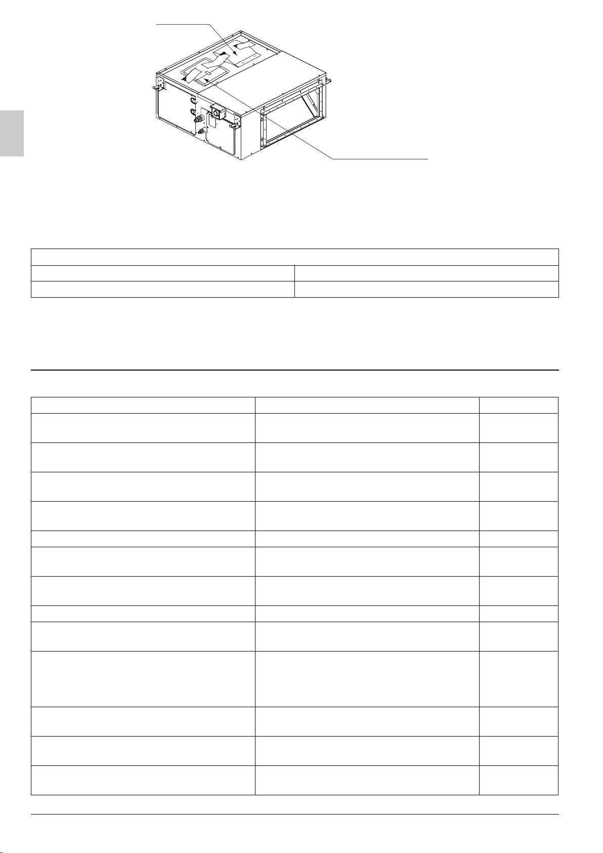
• When opening the unit or moving it after opening, be sure to lift it by holding on to the lifting lugs without
exerting any pressure on other parts, especially, drain piping, and flange.
• Decide upon a line of transport.
• Leave the unit inside its packaging while moving, until reaching the installation site. Use a sling of soft
rial, where unpacking is unavoidable or protective plates together with a rope when lifting, t
mate
damage
or scratches to the unit.
• Refer to the installation manual of the outdoor unit for items not described in this manual.
• Do not dispose of any parts necessary for installation until the installation is complete.
• In order to protect the indoor unit from damage, use packing materials to protect the unit after carrying until
the installation starts.
• Do not use the unit in locations with high salt content in the air such as beachfront property, locations where
the voltage fluctuates such as factories, or in automobiles or marine vessels.
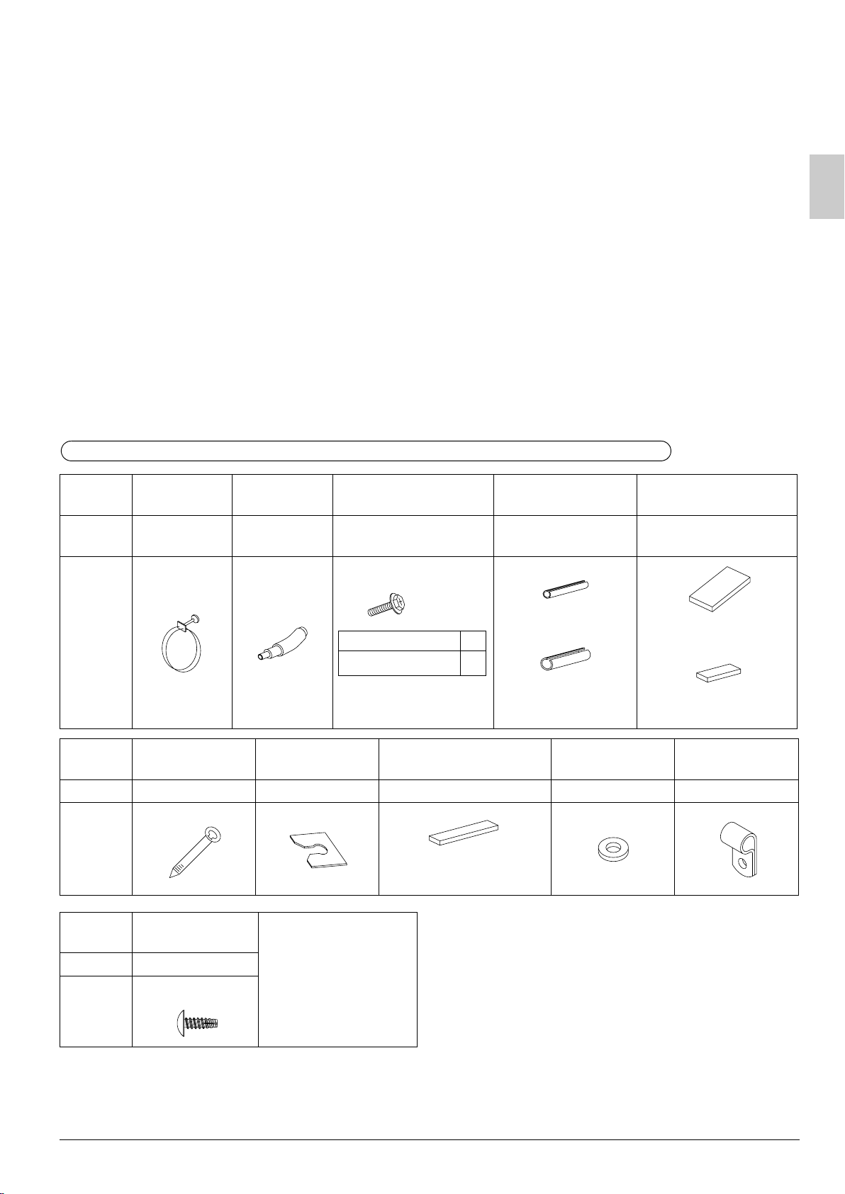
2-1 ACCESSORIES
Check the following accessories are included with your unit.
Refer to Fig. 1 for the location of the accessories.
Do not dispose of any parts necessary for installation until the installation is completed.
Name
Metal clamp
(1)
Quantity 1 pc. 1 pc.
Drain hose
(2)
Screws for duct
flanges (3)
As described in table
below
Insulation for
fitting
1 each –
Sealing pad
o avoid
Thin
1 pc.
Large (Dark gray) (6)
Shape
M5×16
20 • 24 type
36 • 45 • 48 type
18
26
for liquid pipe (4)
Thick
for gas pipe (5)
2 pcs.
Middle (Dark gray) (7)
Name Clamp (8)
Washer fixing
plate (9)
Wire sealing material
(10)
Washer (11)
Wire fixing
bracket (12)
Quantity 9 pcs. 4 pcs. 2 pcs. 8 pcs. 2 pcs.
Shape
Small (Gray)
Name
Quantity 2 pcs.
Wire fixing screw
(13)
(Other)
• Operation manual
M4×8
• Installation manual
Shape
English
4
Page 6
(1) - (13)
Operation manual
Installation manual
Fig. 1
2-2 OPTIONAL ACCESSORIES
• The optional remote controller are required for this indoor unit.
• These are two types of remote controllers: wired and wireless. Select a remote controller according to
customer request and install in an appropriate place.
(When installing, follow the instructions in the manual included with the remote controller.)
Remote controller
epyt deriW
BRC1C61
/ BRC1D61 / BRC1E62
26C4CRBepyt sseleriW
• BRC4C62 cannot be used for the indoor unit FBQ48EAVMK. If required, use wireless type BRC4C64
FOR THE FOLLOWING ITEMS, TAKE SPECIAL CARE DURING CONSTRUCTION AND
CHECK AFTER INSTALLATION IS FINISHED.
a. Items to be checked after completion of work
k
cehCrucco ot ylekil si tahw ,enod ylreporp ton fIdekcehc eb ot smetI
Are the indoor unit and outdoor unit fixed
firmly?
Is the outdoor unit fully installed?
Is the gas leak test finished?
Is the unit fully insulated? (Refrigerant piping, drain piping, and duct)
Does drainage flow smoothly? Condensate water may drip.
Does the power supply voltage correspond
to that shown on the name plate?
Are wiring and pipi
Is the unit safely grounded? It may result in electric shock.
Is wiring size according to specifications?
Is something blocking the air outlet or inlet
of either the indoor or outdoor units?
(This can lead to malfunction or decreased
performance due to decreased air volume.)
Does the cold air (warm air) blow properly
during the cooling (heating) operation?
Are refrigerant piping length and additional
refrigerant charge noted down?
Has the field setting done (as necessary)?
ng correct?
The unit may drop, vibrate or make noise.
The unit may malfunction or components
burn out.
It may result in insufficient cooling or
heating.
Condensate water may drip.
The unit may malfunction or the
components burn out.
The unit may malfunction or the
components burn out.
The unit may malfunction or the
components burn out.
It may result in insufficient cooling or
heating.
It may result in insufficient cooling or
heating.
The refrige
clear.
It may result in insufficient cooling or
heating.
rant charge in the system is not
English5
Page 7
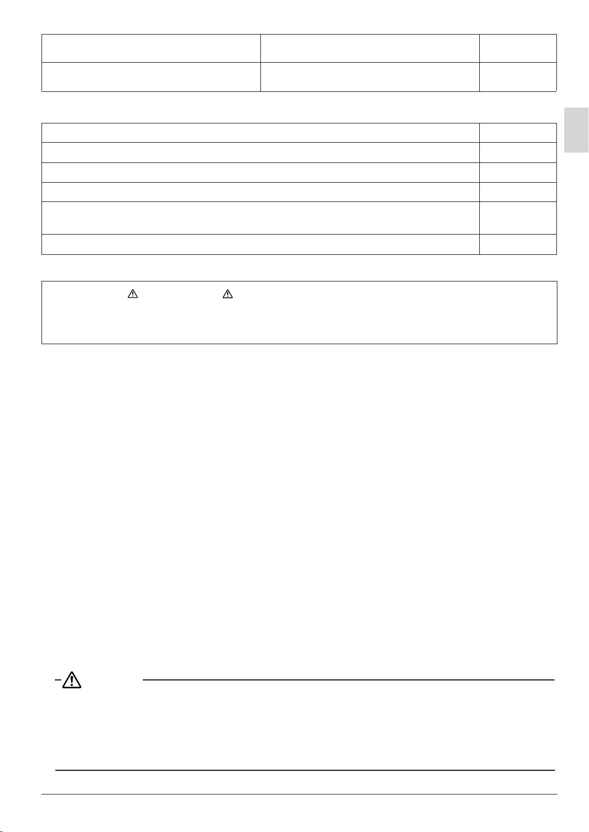
Did you set the external static pressure?
Did you check that no wiring connection
screws were loose?
b. Items to be checked at time of delivery
* Also review the “1. SAFETY PRECAUTIONS”
Items to be checked Check
Did you attach the control box lid, the air filter, air inlet grille and air outlet grille?
Did you explain about operations while showing the instruction manual to your customer?
Did you hand the instruction manual over to your customer?
Did you explain the customer the handling and cleaning methods of the field supplies
(e.g., the air filter, air inlet grilles, and air outlet grille)?
It may result in insufficient cooling or
heating.
Electric shock or fire.
Did you deliver instruction manual, if any, for the fiel
Points for explanation about operations
The items with WARNING and CAUTION marks in the instruction manual are the items
pertaining to possibilities for bodily injury and material damage in addition to the general usage
the product. Accordingly, it is necessary that you make a full explanation about the described
of
con
tents and also ask your customers to read the instruction manual.
d supplies to the customer?
2-3 NOTE TO THE INSTALLER
• Be sure to instruct customers how to properly operate the unit (especially cleaning filters, operating
ent functions, and adjusting the temperature) by having them carry out operations themselves while
differ
looking
at the manual.
3. SELECTING INSTALLATION SITE
When opening the unit or moving it after opening, be sure to lift it by holding on to the hanger bracket without
•
exerting any pressure on other parts, especially piping (refrigerant piping and dr
• Please attach additional thermal insulation material to the unit body when it is believed that the relative
humidity in the ceiling exceeds 80%.
•
Use glass wool, polyethylene foam, or similar with a thickness of 10 mm or more as thermal insulation material.
ain piping) and other resin parts.
(1) Select an installation site where the following conditions are fulfilled and that meets your
cus
tomer’s approval.
• Where optimum air distribution can be ensured.
• Where nothing blocks air passage.
• Where condensate can be properly drained.
• Where the ceiling is strong enough to bear the indoor unit weight.
• Where the false ceiling is not noticeably on an incline.
• Where sufficient clearance for mainte
• Where there is no risk of flammable gas leakage.
• Where piping between indoor and outdoor units is possible within the allowable limit.
(Refer to the installation manual for the outdoor unit.)
CAUTION
• The indoor and outdoor units and the power supply wiring and remote controller cord must be installed
at least 1m away from any televisions or radios. This is to prevent interference with picture and sound
reception. (Interference may occur even at 1m away depending on the reception quality.)
• If installing the wireless kit, the distance of the signal sent from the remote controller might be shorter if
there are fluorescent lights which are electrically started (such as with inverters, rapid starters, etc.) in
the room. The indoor unit should be installed as far away from fluorescent lights as possible.
English
nance and service can be ensured. (Refer to Fig. 2)
6
Page 8
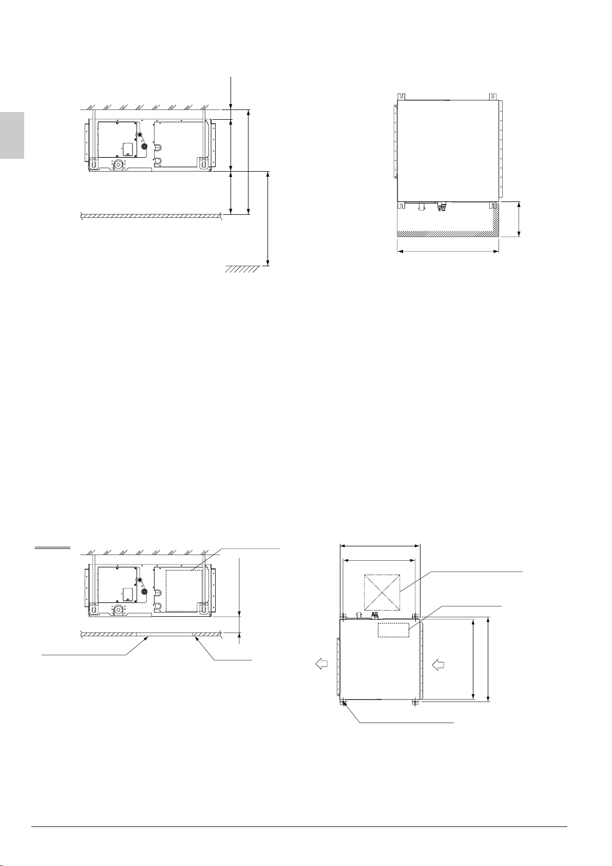
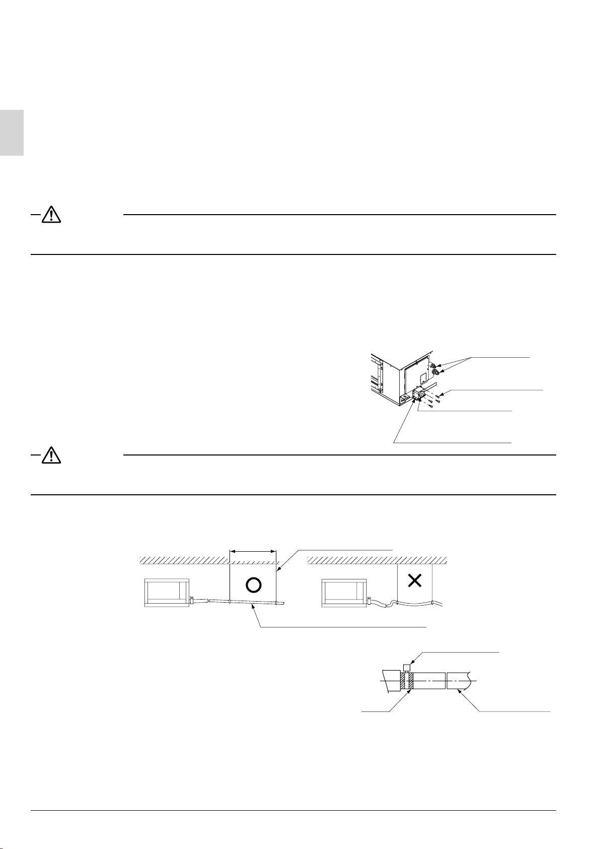
(2) Use suspension bolts for installation. Check if the location for the installation is strong enough to support
the weight of the unit, reinforce it if necessary, and install using suspension bolts.
(length: mm)
Min. 20Min. 300
*H1=300
*H2=Min. 620
Ceiling
Min. 2500
Floor surface
(If no ceiling board is provided.)
*The H1 dimension indicates the height of the
product.
*Determine the H2 dimension by maintaining
a downward slope of at least 1/100 as
specified in “7. DRAIN PIPING WORK”.
Min. 700 (service space)
[Required installation place]
The dimensions indicate the
minimum required space of
installation.
Fig. 2
Min. 450
4. PREPARATIONS BEFORE INSTALLATION
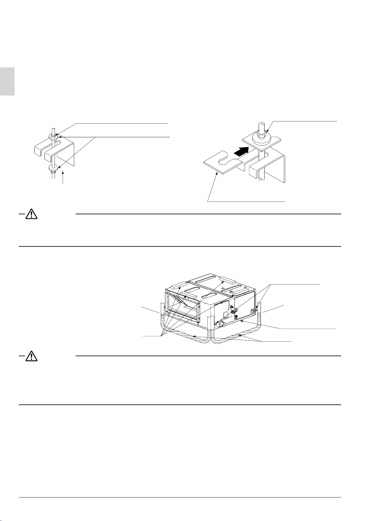
(1) Check the positional relationship between the ceiling opening hole and the hanging bolt of the unit.
• For the maintenance, inspection, and other servicing purposes of the control box, prepare one of the
lowing service spaces.
fol
1. Inspection hatch 1 (450 × 450) for the control box and a minimum space of 300 mm for the lower part
of the product. (Refer to Fig. 3)
2. Inspection hatch 1 (450 × 450) for the control box and inspection hatch 2 for the lower pa
prod
uct (see axial direction view A-1). (Refer to Fig. 4)
3. Inspection hatch 3 for the lower part of the product and the lower part of the control box (see axial
direction view A-2). (Refer to Fig. 4)
rt of the
Case 1
Inspection hatch
Control box
*H3=Min. 300
Ceiling
Air outlet
Fig. 3
700
631
(Hanging bolt pitch)
Bottom of unit
Hanging bolt (× 4)
Inspection hatch 1
(450×450)
Control box
B
C
Air inlet
(Hanging bolt pitch)
English7
Page 9

Case 2, 3
Inspection hatch
(Ceiling opening)
Control box
Inspection hatch 1
(450×450)
Min. 200B
Inspection hatch 3
(Same as the indoor
unit size +300 or more)
Control box
Inspection hatch
*H3=Min. 20
A
Ceiling
Control box
Min. D=B+300
007007
Inspection hatch 2
(Same as the indoor
unit size or more)
*Determine the H3 dimension by
maintaining a downward slope
of at least 1/100 as specified in
“7. DRAIN PIPING WORK”.
Axial direction view A-1 Axial direction view A-2
Fig. 4
Model B C D
20
• 24 type
36 • 45 • 48 type
1000 1038 1300
1400 1438 1700
(length: mm)
(2) Mount the canvas ducts to the air outlet and inlet so that the vibration of the air conditioner will not be
mitted to the duct or ceiling. Apply a sound-absorbing material (insulation material) to the inner wall
trans
of the
duct and vibration insulation rubber to the hanging bolts (refer to 8. DUCT WORK).
(3) Open installation holes (if the ceiling already exists).
• Open the installation holes on the ceiling. Lay the refrigerant piping, drain piping, power line,
transmis
sion wiring, and remote controller wiring for the piping and wiring connection port of the unit.
In the case of the installation of a wireless remote controller, refer to the installation manual provided
with the wireless remote controller.
Refer to 6. REFRIGERANT PIPING WORK, 7. DRAIN PIPING WORK, and 10. WIRING EXAMPLE
AND HOW T
• The ceili
O SET THE REMOTE CONTROLLER.
ng framework may need reinforcement in order to keep the ceiling horizontal and prevent the
vibration of the ceiling after the installation holes are opened. For details, consult your construction or
interior contractor.
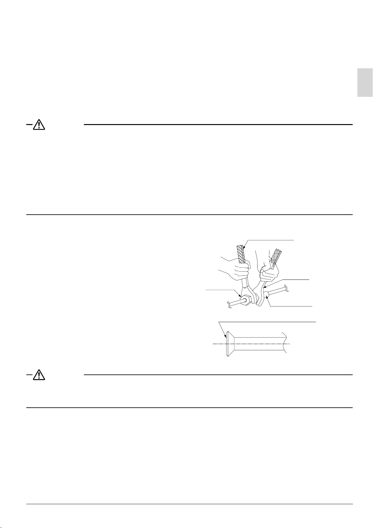
(4) Install the hanging bolts. Make sure that the hanging bolts are M10 in size.
• Use hole-in anchors if the hanging bolts
already exist; otherwise use embedded
inserts and embedded foundation bolts so that
Installation example
Ceiling slab
they will withstand the weight of the unit.
Adjust the distance to the ceiling surface in
Anchor
advance.
Long nut or turn-buckle
English
Hanging bolt
Indoor unit
Note) All the above parts are field supplied.
8
Page 10
5. INDOOR UNIT INSTALLATION
It may be easier to install accessories (sold separately) before installing the indoor unit. Refer to the
〈
installation manuals provided to the accessories as well.〉
As for the parts to be used for installation work, be sure to use the provided accessories and specified parts
designated by our company.
(1) Temporally install the indoor unit.
• Connect the hanging brackets to the hanging bolts. Be sure to use and tighten the nut and washer (11) for
each hanging bracket from both upper and lower sides of the hanging bracket.
the fall of the washer (11) for the hanging bracket can be prevented if the washing fixing plate (9) is used.
Part to be procured in the field
Washer (11) (accessory)
Insert
Tighten from above and below
(Double nut)
Fig. 5
Washer fixing plate (9)
(accessory)
(Refer to Fig. 5)
Nut on the upper side
At that time,
]srehsaw fo dohtem gnixiF[]stekcarb gnignah gnixiF[
CAUTION
• During the installation work, perform the curing of the air outlet and protect the resin drain pan of
the indoor unit from the intrusion of foreign substances, such as welding spatters.
Otherwise, water leakage may occur as a result of damage, such as hole damage, to the resin drain pan.
(2) Make adjustments so that the unit will be in the right position.
(3) Check the level of the unit.
(4) Remove the washer fixing plates for
the falling prevention of the washers
for the hanging brackets, tighten the
nuts on the upper side, and securely
fix the unit.
Level
CAUTION
• Use the level and check that the unit is installed horizontally. (4-directions)
• In the case of using a vinyl tube in place of the level, put the both edges of the vinyl tube in close contact
with the bottom of the product to make levelness adjustment.
If the unit is installed at a slant with the drain pipe side set high, in particular, the float switch will not operate
normally and water leakage may result.
Hanging bracket
Bottom of product
Vinyl tube
9
English
Page 11
6. REFRIGERANT PIPING WORK
For refrigerant piping of outdoor units, see the installation manual attached to the outdoor unit.〉
〈
〈Execute heat insulation work completely on both sides of the gas piping and the liquid piping. Otherwise, a
water leakage can result sometimes.〉
(When using a heat pump, the temperature of the gas piping can reach up to approximately 120°C, so use
insulation which is sufficiently resistant.)
〈Also, in cases where the temperature and humidity of the refrigerant piping sections might exceed 30°C or
RH80%, reinforce the refrigerant insulation. (20mm or thicker) Condensate may form on the surface of the
insulating material.〉
〈Be sure to chec
erant will prevent normal operation of the unit.)〉
refrig
CAUTION
This product is designed to be used with new refrigerant (R410A). Always observe the precautions on the
following when installing.
• Use a pipe cutter and flare suitable for the type of refrigerant.
• Apply ester oil or ether oil around the flare section before connecting.
• Use the flare nut provided to the unit. Do not use a different flare nut (class 1), or otherwise refrigerant
leakage may result.
• To prevent dust, moisture or other foreign matter from infiltrating the tube, either pinch the end or cover
it with tape.
• Do not allow anything other than the designated refrigerant to get mixed into the refrigerant circuit, such
as air, etc. If any refrigerant gas leaks while working on the unit, ventilate the room thoroughly right away.
k the type of R410A refrigerant to be used before doing any work. (Using an incorrect
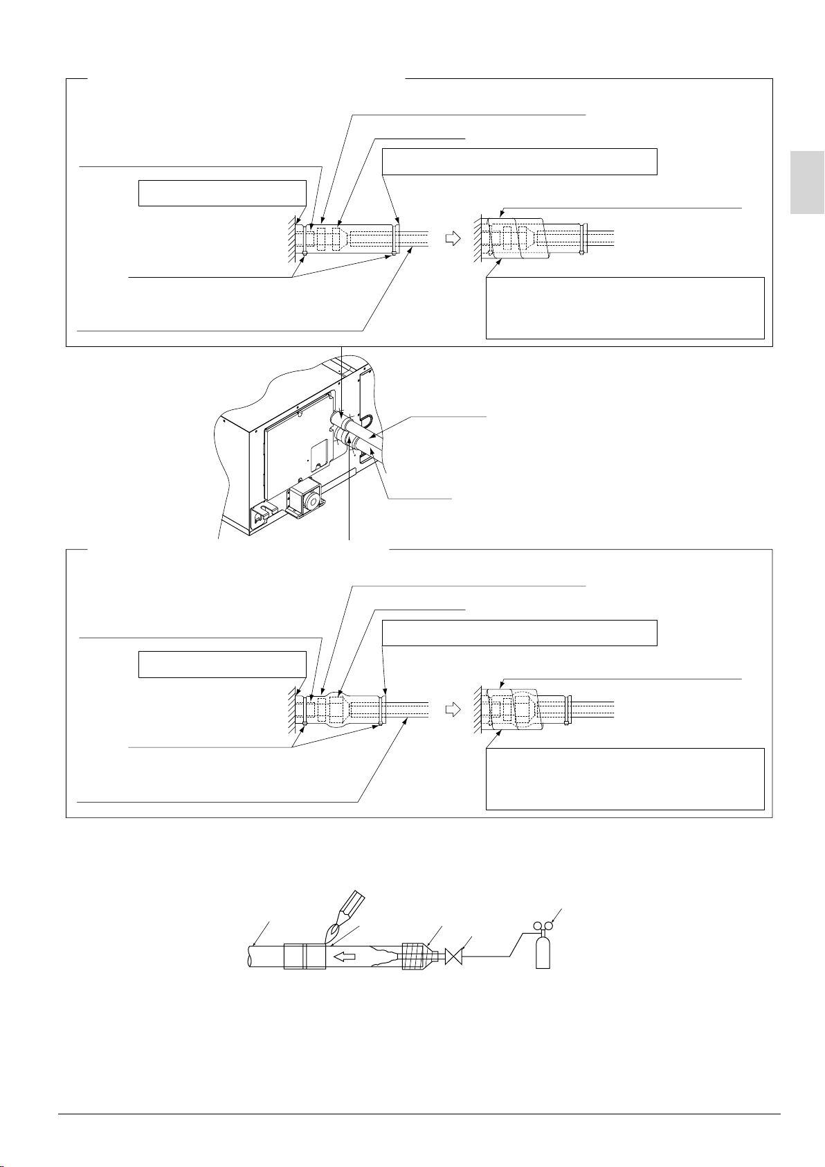
• The outdoor unit is charged with refrigerant.
• Be sure to use both a spanner and torque wrench
together, as shown in the drawing, when connecting
or disconnecting pipes to/from the unit.
(Refer to Fig. 6)
• Refer to “Table 1” for the dimensions of flare nut
spaces.
• Use the flare nut included with the unit main body.
• When connecting the flare nut, apply ester oil or
ether oil to the flare section (inside only), and spin
3
-
4 times before screwing in.
(Refer to Fig. 7)
CAUTION
• Do not let oil get on the screw holders on the dressing board. Oil can weaken the screw holders.
• Refer to “Table 1” to determine the proper tightening torque.
• Be careful not to damage the flare section.
Flare nut
Coat here with ester or ether oil.
Torque wrench
Spanner
Piping union
Fig. 7
Fig. 6
10English
Page 12
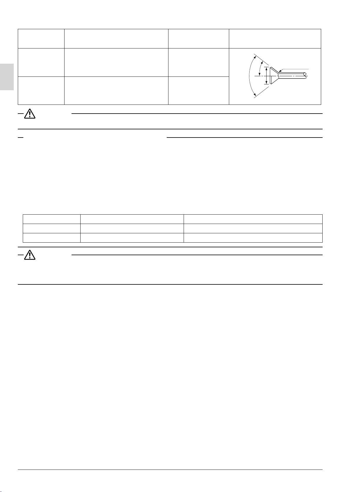
Table 1
Pipe size Tightening torque (N·m)
φ 9.5 (3/8”) 32.7 – 39.9 12.8 – 13.2
Flare dimensions
A (mm)
2˚
±
90˚
2˚
±
45˚
Flare
R0.4-0.8
A
φ 15.9 (5/8”) 61.8 – 75.4 19.3 – 19.7
CAUTION
• Over-tightening the flare nut may break it and/or cause the refrigerant to leak.
Not recommendable but in case of emergency
You must use a torque wrench but if you are obliged to install the unit without a torque wrench, you may
follow the installation method mentioned below.
After the work is finished, make sure to check that there is no gas leak.
When you keep on tightening the flare nut with a spanner, there is a point where the tightening torque
suddenly increases. From that position, further tighten the flare nut the angle shown below:
Unless followed the tightening instruction (it is loose tightening), it will lead to the refrigerant leakage (slow
leak) and the device malfunction (it does not sufficiently cool or heat).
Pipe siz
φ mm002 .
e Further tightening angle Recommended arm length of tool
xorppAseerged 09 ot 06)”8/3( 5.9
φ mm003 .xorppAseerged 06 ot 03)”8/5( 9.51
CAUTION
For local insulation, be sure to insulate local piping all the way into the pipe connections inside the
machine.
Exposed piping may cause condensation or burns on contact.
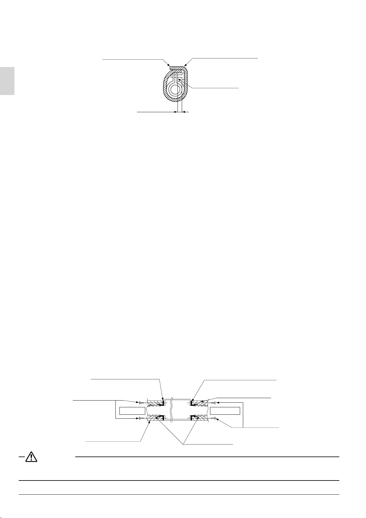
• Make absolutely sure to execute heat insulation works on the pipe-connecting section after checking gas
leakage by thoroughly studying the following figure and using the attached heat insulating materials for
ting (4) and (5). (Fasten both ends with the clamps (8).) (Refer to Fig. 8)
fit
• Wrap the middle sealing material (7) around the insulation for fitting (4) and (5) for the joint (flare nut part).
• Make sure that the joint of the insulation for fitting (4) and (5) for the joint on the liquid piping and gas piping
side faces upward.
English11
Page 13
Heat insulation procedure for liquid piping
Insulation for fitting (4) (accessory)
Insulation material for piping
(on unit side)
Attached to the surface.
Main unit
Clamp (8) (accessory)
Insulation material for piping (field supply)
Flare nut joint
Make sure that the seam faces upward.
Middle sealing pad (7) (accessory)
Wrap the insulation material around the
portion from the surface of the main unit
to the upper part of the flare nut joint.
Liquid pipe
Gas pipe
Fig. 8
Heat insulation procedure for gas piping
Insulation for fitting (5) (accessory)
Insulation material for piping
(on unit side)
Attached to the surface.
Flare nut joint
Make sure that the seam faces upward.
Middle sealing pad (7) (accessory)
Clamp (8) (accessory)
Wrap the insulation material around the
Insulation material for piping (field supply)
portion from the surface of the main unit
to the upper part of the flare nut joint.
• When brazing the refrigerant piping, only begin brazing after having carried out nitrogen
substitu
tion or while inserting nitrogen into the refrigerant piping.
Once this is done, connect the indoor unit with a flared or a flanged connection.
Pressure-reducing valve
Refrigerant piping
Part to be
brazed
Nitrogen
Taping
Hands valve
Nitrogen
English
Fig. 9
12
Page 14
• Nitrogen should be set to 0.02MPa with a pressure-reducing valve if brazing while inserting nitrogen into
the piping. (Refer to Fig. 9)
• Do not use flux when brazing refrigerant piping. Therefore, use the phosphor copper brazing filler metal
(BCuP-2: JIS Z 3264/B-Cu93P-710/795: ISO 3677) which does not require flux.
(Flux has extremely harmful influence on refrigerant piping systems. For instance, if the chlorine based flux is
used, it will cause pipe corrosion or, in particular, if the flux contains fluorine, it will damage the r
• When the airtight test is performed for the indoor unit and inter-unit piping after indoor unit installation, be
sure to refer to the installation manual for the indoor unit or technical guide for airtight pressurization and
refrigerant piping installation.
• Shortage of refrigerant due to air purge or losing the additional refrigerant charging may cause the failure
of the unit (does not sufficiently cool or heat).
Be sure to refer the installation manual or the engineering guide for the outdoor unit at the refrigerant piping
work.
CAUTION
• Do not use anything such as the oxidation inhibitor when brazing. (Residues may result in the clogging pipe
or parts damage.)
efrigerant oil.)
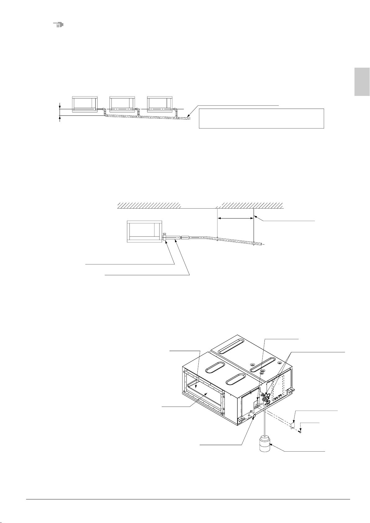
7. DRAIN PIPING WORK
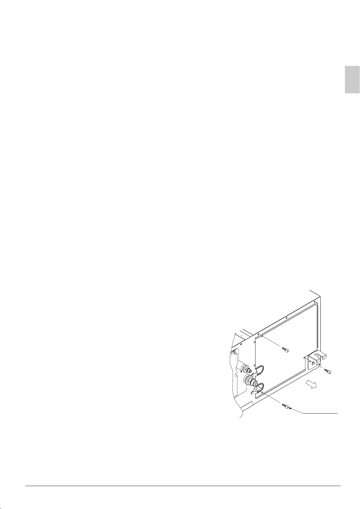
(1) Remove the drain socket cover. (for transportation)
(2) Conduct drain piping work.
Check that the piping ensures proper draining.
• Make sure that the diameter of the piping excluding the rising
part is the same as or larger than the diameter of the
connect
of 32 mm
• Make sure that the piping is short enough with a downward
slope of at least 1/100 and that there is no air bank formed.
No drain trap is required.
ing pipe (vinyl chloride pipe with an outer diameter
and a nominal inner diameter of 25 mm).
Drain socket cover
(for transportation)
Refrigerant
piping
Screw (4 portions)
Drain socket
CAUTION
• The drain piping will be clogged with water and water leakage may result if the water is accumulated in the
drain piping.
• Conduct drain-up piping work if the gradient is insufficient.
• Attach some support brackets at 1 to 1.5 m intervals for the prevention of piping deflection.
1 - 1.5 m
Downward slope of at least 1/100
• Be sure to use the drain hose (2) and metal clamp (1).
Insert the drain hose (2) deep into the base of the drain
socket, and securely fasten the metal clamp (1) within the
taped part on the insertion front end of the hose.
Be sure to fasten the screw of the metal clamp (1) until the
margin of the screw thread decreases to 4 mm or less.
Supporting hanger
Tape
Metal clamp (1)
(accessory)
Drain hose (2)
(accessory)
13
English
Page 15
NOTE
Be sure to follow the instructions as below.
• Do not connect the drain piping directly to a sewer that smells of ammonia.
The ammonia in the sewer may reach through the drain piping and corrode the heat exchanger of the
indoor unit.
• Do not bend or twist the provided drain hose (2) in order not to impose excessive force on the hose.
(Doing so may result in water leakage.)
• Take the procedure shown in the following illustration to perform concentrated drain piping.
Concentrated drain piping
Maintain a downward slope of at least
1/100 so that no air bank will be formed.
Min. 100 mm
The drain piping will be clogged with
water and water leakage may result if the
water is accumulated in the drain piping.
• Select the diameter of the concentrated drain piping to suit the capacity of equipment connecting to the
concentrated drain piping (see the equipment design sheet).
Ceiling slab
1 - 1.5 m
Support bracket
Metal clamp (1) (accessory)
Drain hose (2) (accessory)
(3)
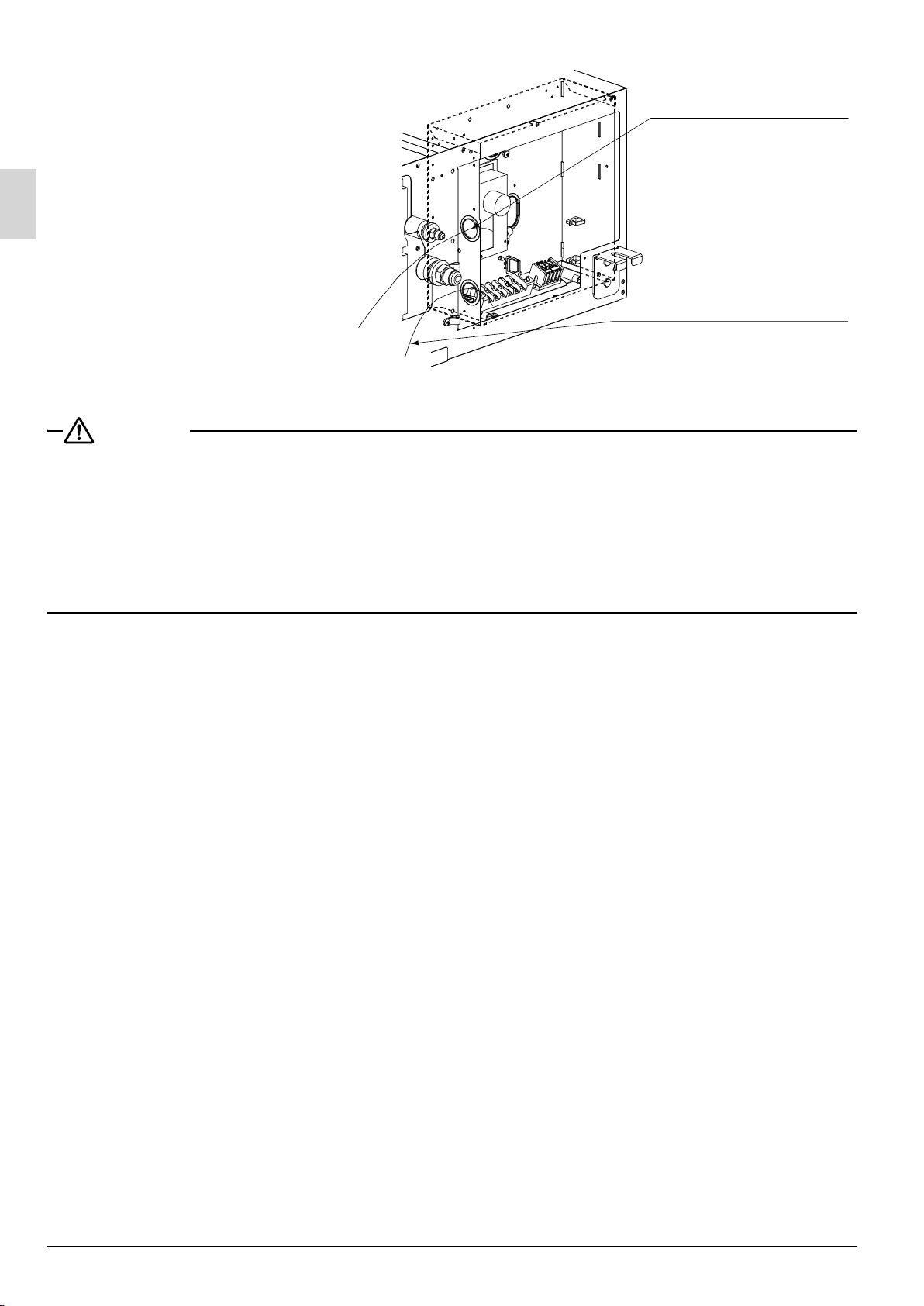
Check the smooth draining of the piping on completion of the installation of the piping.
• Provide approximately one liter of water gradually into the drain pan through the water inlet on the
bottom of the drain socket or the outlet.
(4) Be sure to conduct heat insulation work on the following portions, or otherwise water leakage may
occur as a result of dew condensation.
• Drain piping indoors
• Drain socket
Drain pan
Water inlet
Refrigerant piping
English
Air outlet
Drain socket
Water inlet lid
Screw
Plastic water
container
14
Page 16
• On completion of the drainage check, refer to the following illustration, and use the provided large
seal
ing pad (6) and heat insulate the metal clamp (1) and drain hose (2).
Make sure that the
seam faces upward.
4 mm max.
Large sealing pad (6)
(accessory)
Metal clamp (1)
(accessory)
8. DUCT WORK
Pay the utmost attention to the following items and conduct the ductwork.
• Check that the duct will not be in excess of the setting range of external static pressure for the unit. (Refer
to the technical datasheet for the setting range.)
• Attach a canvas duct each to the air outlet and air inlet so that the vibration of the equipment will not be
transmitted to the duct or ceiling.
Use a sound-absorbing material (insulation material) for the lining of the duct
rubber to the hanging bolts.
• At the time of
the drain pan for the filter.
• If the metal duct pass through a metal lath, wire lath, or metal plate of a wooden structure, separate the duct
and wall electrically.
• Be sure to heat insulate the duct for the prevention of dew condensation. (Material: Glass wool or styrene
foam; Thickness: 25 mm)
• Be sure to attach the field supply air filter to the air inlet of the unit or field supply inlet in the air passage on
the air suction side. (Be s
• Explain the operation and washing methods of the locally procured components (i.e., the air filter, air inlet
grille, and air outlet grille) to the customer.
• Locate the air outlet grille on the indoor side for the prevention of drafts in a position where indirect contact
with people.
The air conditioner incorporates a function to adjust the fan to rated speed automatically.
•
Therefore, do not use booster fans midway in the duct.
duct welding, perform the curing of the duct so that the sputter will not come in contact with
ure to select an air filter with a duct collection efficiency of 50 weight percent.)
and apply vibration insulation
(11. FIELD SETTING)
Connection method of ducts on air inlet and outlet sides.
• Connect the field supply duct in alignment with the in
• Connect the flange and unit with the flange connection screw (3).
• Wrap aluminum tape around the flange and duct joint in order to prevent air leakage.
Flange on air inlet side
(provided with the unit)
Screws for duct
flanges (3)
(accessory)
Insulation material
(field supply)
CAUTION
Connect the flange and unit with the flange connection screw (3) regardless of whether the duct is connected to the air inlet side.
Air inlet
ner side of the flange.
Flange on air outlet side
(provided with the unit)
Insulation material
(field supply)
Unit
Canvas duct
(field supply)
Air outlet
Screws
for duct
flanges (3)
(accessory)
English15
Page 17
9. ELECTRIC WIRING WORK
WIRING INSTRUCTIONS
• Electric wiring work must be conducted by electrician authorized by power companies. (Only licensed
trician can conduct electric work and earth connections.)
elec
• All wiring must be performed by an authorized electrician.
• Be sure to install an earth leakage breaker to the outdoor unit.
(This installation of an earth leakage breaker is mandatory for the prevention of electric shocks and fire
disasters.)
• Install the earth leakage breaker which can handle harmonics.
(This unit has an inverter, so an interrupter capable of handling high frequencies is needed to prevent
mal
function of the interrupter itself.)
e sure to use earth leakage breaker dedicated for earth leakage protection in combination with the load
• B
break switch with fuse or breaker f
• Make sure that 230V is specified wiring between the indoor and outdoor units and between indoor units.
• Do not turn on the power supply (of the indoor unit) until all the installation work is completed.
• Be sure to earth the air conditioner.
• Do not connect the earth wire to gas pipes, plumbing pipes, lightning rods, or telephone earth wires.
• Gas pipes: might cause explosions or fire if gas leaks.
• Plumbing: no earth effect if hard vinyl piping is used.
• Telephone earth wires or lightning rods: might cause abnormally high electric potential in the earth
dur
ing lighting storms.
• The earth is ne
appliances and to release the charge built up in the product box by leaked current.
• For electric wiri
• Never connect the power supply wire to the terminal block for remote controller wire, or otherwise the entire
system may be damaged.
• For remote controller wiring details, refer to the installation manual attached to the remote controller.
• Do not touch the printed circuit board ASSY during the wiring work. Otherwise, it may cause damage.
eded in order to reduce the noise generated by the unit’s inverter and influence on other
ng work, refer to also “WIRING DIAGRAM” attached to the unit body.
or wiring.
10. WIRING EXAMPLE AND HOW TO SET THE REMOTE CONTROLLER
10-1 Connection of wiring between units, earth wire and for the remote controller cord
(Remove the control box lid as shown below and connect each wire.)
(1) Remove the control box lid.
Screw
(3 portions)
English
16
Page 18
(2) Lay the wires in the control box
through the wire inlet on the side of
the control box.
Low-voltage wiring inlet
• Remote controller wiring
(Low voltage)
High-voltage wiring inlet
Wiring the units (High voltage)
•
•
Power supply wiring (High voltage)
• Ground wiring (High voltage)
CAUTION
• Do not lay the remote controller wiring along with the wiring the units, power supply wiring or other electric
wiring in the same route. Separate the remote controller wiring at least 50 mm from the wiring the units,
power supply wiring or other electric wiring, or otherwise malfunctions or failures may be caused by
nal electric noise that may interfere with the remote controller wiring.
exter
• For the installation and wiring of the remote controller, refer to the remote controller installation manual
pro
vided with the remote controller.
• For wiring the units, power supply wiring, refer to the wiring diagram as well.
• Be sure to connect the remote controller wiring correctly to the right terminal block (X2M).
English17
Page 19

(3) Follow the instructions below, and lay the wires in the control box.
Fix the wires with clamp (8)
to the wire fixing bracket
provided to the control box.
Power supply terminals (X1M)
Earth L1 2 3 N
Wiring
the units
Power supply
wiring
Connection method of
power supply terminals
Outdoor unit
Indoor unit
Remote controller
wiring (Low voltage)
Twist and fix the upper part so
that the wires will not drop out.
Fix the cord with the
clamp (8) to the wire
fixing bracket provided
to the control box.
Insert the cord into the wire clips
provided with the control box.
PROHIBITED
Never connect wiring the units
and the power supply wiring.
P1 P2 F1 F2
Remote controller
wiring (No polarity)
Connection method of remote
controller terminals (X2M)
• If stranded wires are used,
do not solder the front end
of the wires.
(Terminal block)
(Terminal block)
Match both numbers.
Connecting wiring between units
WARNING
Trim and lay the wiring neatly and attach the control box lid securely.
An electric shock or fire may result if the control box lid catches any wiring or the wires push up the lid.
(4) Put the control box lid, and wrap the wire sealing
material (Small) (10) around the wires so as to
Wire through holes
block the wire through holes.
18English
Page 20

CAUTION
• After all the wiring connections are done, fill in any gaps in the through holes with putty or insulation
(procured locally) to prevent small animals and insects from entering the unit from outside. (If any do get in,
they
could cause short circuits in the control box.)
(5) Mount the provided wire fixing bracket (12) with
the wire fixing screw (13). Fix each wire with the
provided clamp (8).
Precautions to be taken for power supply wiring
Use a round crimp-style terminal for connection to the
power supply terminal block.
Remote controller
wiring
Wiring the units
Power supply wiring
Ground wiring
Fixing use
Clamp (8) (accessory)
Wire fixing bracket (12) (accessory)
Wire fixing screw (13) (accessory)
Attach insulation sleeve
Electric wireRound crimp-style terminal
In case it cannot be used due to unavoidable reasons, be sure to observe the following instructions.
Connect wires of the
same gauge to both
side. (GOOD)
Do not connect wires
of the same gauge to
one side. (WRONG)
Do not connect wires
of different gauges.
(WRONG)
Good Wrong Wrong
(Loose wiring and similar problems may result in abnormal heat build-up.)
• In wiring, make certain that prescribed wires are used, carry out complete connections, and fix the wires so
that external forces are not applied to the terminals.
• If the strand wire is used, do not solder it.
Tightening torque for the terminal screws.
• Use the correct screwdriver for
head of the screw might be damaged, and the screw will not be properly tightened.
• If the terminal screws are tightened too hard, screws might be damaged.
Refer to the table below for the tightening torque of the terminal screws.
tightening the terminal screws. If
the blade of screwdriver is too small, the
19
Tightening torque (N·m)
69.0 ot 08.0rellortnoc etomer rof kcolb lanimreT
44.1 ot 81.1stinu eht gniriw rof kcolb lanimreT
44.1 ot 81.1lanimret htraE
English
Page 21

Specifications for field wire.
• Remote controller transmission and power supply wiring are field supply. Refer to Table 2.
• Follow 60245 IEC 57 for wiring type (insulating sheath specification, etc.)
Table 2
2
)
2.5 –
Wiring the units
Remote
controller cord
Type Field fuses Wire spec.
20
45 • 48 –
36
• 24 • – 4 cores (incl. earth wire)
4 cores (incl. earth wire)
Shield wire
– –
Size(mm
0.75-1.25 Max.500m*
2 cores
Power supply
wiring (for Fan)
*Total length of system wiring if using group control.
• Wiring specifications assume a voltage drop of 2%.
WIRING EXAMPLE
CAUTION
Be sure to install an earth leakage breaker to the outdoor unit.
Installation of an earth leakage breaker is mandated to avoid electric shocks or fire.
Length
––A51–
For the wiring of outdoor units, refer to the installation manual attached to the outdoor units.
Confirm the system type.
• Pair type: 1 remote controller controls 1 indoor unit. (standard system)
• Group control: 1 remote controller controls up to 16 indoor units. (All indoor units operate according to
te controller) (Refer to Fig. 10)
remo
the
• 2 remote controllers control: 2 remote controllers control 1 indoor unit. (Refer to Fig. 14)
Pair type
Main power supply
Earth leakage breaker
Outdoor unit
1 2 3
P1
P2
P1
P2
Remote controller
(Optional accessory)
Earth leakage breaker
Power supply
single phase
L
N
50Hz/60Hz
1
2
3
L
N
Indoor unit
220-240V/230V
Group control: 1 remote controller controls up to 16 indoor units. (All indoor units operate according to the
remote controller) (Refer to Fig. 10)
n this case, all the indoor units in the group will operate in accordance with the group control remote contro
•
I
FBQ48EAVMK is only 50Hz model.
•
ller.
English
20
Page 22

• For group control remote controller, choose the remote controller that suits the indoor unit which has the
most functions (as attached swing flap)
Group control
Outdoor unit 1
Outdoor unit 2
Indoor unit 1
Indoor unit 2
Indoor unit 16
Group control remote controller
Wiring Method
(1) Remove the control box lid. (See ‘‘9. ELECTRIC WIRING WORK’’.)
(2) Cross-wire the terminal block for remote controller (P
) inside the control box. (There is no
1 P2
polarity.) (Refer to Fig. 10 and Table 2)
Indoor unit 1 Indoor unit 2
2P1P2P1P
Terminal for remote
controller wiring
To next unit
Group control remote controller
Two remote controllers control (Controlling 1 indoor unit by 2 remote controllers)
• When using 2 remote controllers, one must be set to “MAIN” and the other to “SUB”.
Outdoor unit 16
Fig. 10
Fig. 11
MAIN/SUB CHANGEOVER
(1) Insert a screwdriver into the recess between the upper and lower part of remote controller and, working
from the 2 positions, pry off the upper part. (The remote controller PC board is attached to the upper part
of remote controller.) (Refer to Fig. 12)
Fig. 12
Upper part of
remote controller
Lower part of
Insert the screwdriver
remote controller
here and gently work
off the upper part of
remote controller.
21
English
Page 23

(2) Turn the main/sub changeover switch on one of the two remote controller PC boards to “S”. (Leave the
switch of the other remote controller set to “M”.) (Refer to Fig. 13)
Fig. 13
S
(Factory setting)
S
M
Remote
controller
(Only one remote
controller needs
S
M
PC board
to be changed if
factory settings
have remained
untouched.)
Wiring Method (See “9. ELECTRIC WIRING WORK’’.)
(3) Remove the control box lid
(4) Add remote controller 2 (slave) to the terminal block for remote controller (P
, P2) in the control
1
box. (There is no polarity.)
Outdoor unit
P1 P2
Terminal for remote
controller wiring
Remote
controller 1
Remote
controller 2
Remote
controller 1
(Master)
Remote
controller 2
(Slave)
Fig. 14
11. FIELD SETTING
NOTE
• Before 12. TEST OPERATION, be sure to make the following field settings as explained in 11. FIELD
SETTING.
• Be sure to check that the outdoor unit has been wired.
• Make sure the control box lids are closed on the indoor and outdoor units.
• Field setting must be made from the remote controller in accordance with the installation condition.
• Setting can be made by changing the “MODE NO.”, “FIRST CODE NO.”, and “SECOND CODE NO.”.
• For setting and operation, refer to the “FIELD SETTING” in the installation manual of the remote controller.
• Do not set numbers unless mentioned in the table.
22English
Page 24

With Wireless Remote Controller Used
Set the wireless remote controller address before using the wireless remote controller.
For the setting method of the address, refer to the operation manual provided with the wireless remote
con
troller.
NOTE
• A “MODE NO.” is set on a group basis. To make a mode setting on a room unit basis or check the setting
made, however, set the corresponding mode number in the parentheses.
1. Settings for Optional Accessories
• In the case of connecting optional accessories, refer to the operation manuals provided with the optional
accessories and make necessary settings.
2. External Static Pressure Settings
Make settings in either method (a) or method (b) as explained below.
(a) Use the airflow auto adjustment function to make settings.
Airflow auto adjustment: The volume of blow-off air is automatically adjusted to the rated quantity.
NOTE
Be sure to check that the external static pressure is within the rated range before making the settings.
the external static pressure is beyond the rated range, no automatic adjustments will be made and an
If
air
flow rate insufficiency or water leakage may result. (Refer to the relevant technical datasheet for the
rated
range of the external static pressure.)
Table 3
(1)Check that power supply wiring and wiring the units to the air conditioner is completed along with
duct installation. If a closing damper is installed in the air-conditioning system, make sure that the
closing damper is opened. Furthermore, check that the
air passage on the suction side.
(2)If there are a number of air outlets and inlets, adjust the throttles so that the airflow rate of each air
outlet and inlet will coincide with the designed airflow rate. At that time, operate the air conditioner
in “fan operation mode”. To change the airflow rate, press and set the airflow adjustment button of
the remote controller to H, or L.
(3)Make settings for airflow automatic adjustment. After setting the air conditioner to “fan operation
mode”, stop the air conditioner, go to “FIELD SET MODE”, select “MODE NO. 21” (11 in the case
of group settings), set the setting “FIRST CODE NO.” to 7, and set the setting “SECOND CODE
NO.” to 03.
Return t
operation lamp will be lit and the air conditioner will go into fan operation for airflow automatic
adjustment. Do not adjust the throttles of the air outlets or inlets during automatic adjustment of the
air conditioner. After the air conditioner runs approximately one to eight minutes, the air conditioner
will finish airflow adjustment automatically, the operation lamp will be turned OFF, and the air
con
MODE NO. FIRST CODE NO. Setting contents
o normal mode after these settings, and press the ON/OFF OPERATION button. Then the
ditioner will come to a stop.
11 (21 tnemtsujda wolfriA7)
SECOND CODE NO.
OFF Completion of airflow adjustment Start of airflow adjustment
air filter as a field supply is attached to the
302010
(4)After the air conditioner stops operating, check with “MODE NO. 21” on an indoor unit basis that 02
is set for the “SECOND CODE NO.” in Table 3. If the air conditioner does not stop operating
auto
matically or the “SECOND CODE NO.” is not
check
the defective point.
02, repeat steps from (3). If error is displayed,
English23
Page 25

CAUTION
• If there is any change after airflow adjustment in the ventilation paths (e.g., the duct and air outlet), be sure
to make airflow auto adjustment again.
• Consult your Daikin representative if there is any change in the ventilation paths (e.g., the duct and air
out
let) after the test operation is finished or the air conditioner is moved to another place.
(b) Select External Static Pressure with Remote Controller
Check that 01 (OFF) is set for the “SECOND CODE NO.” in “MODE NO. 21” for airflow adjustment on an
indoor unit basis in Table 3. The “SECOND CODE NO.” is set to 01 (OFF) at factory set. Change the
OND CODE NO.” as shown in Table 4 according to the external static pressure of the duct to be
“SEC
connected.
(1)The “SECOND CODE NO.” is set to 01 (an external static pressure of 50 Pa) at
factory set.
Table 4
External Static Pressure
(Pa)
50
MODE NO.
Note
FIRST CODE NO. SECOND CODE NO.
01
60 02
70 03
80 04
90 05
100 06
110 07
120 08
13 (23) 06
130 09
140 10
150 11
160 12
180 13
200 14
NOTE
“Mode No.” setting is done in a batch for the group. To make or confirm settings for an individual unit, set
the Mode No. shown in parentheses.
CAUTION
Keep in mind that a shortage of airflow quantity or water leakage will result because the air conditioner will
be operated outside the rated range of airflow quantity if the external static pressure is wrongly set.
3. Filter Sign Settings
• The remote controller is provided with an LCD that tells the time of air filter cleaning.
• If the air conditioner is used in places with excessive dust, change the “SECOND CODE NO.” as shown
in Table 5. The “SECOND CODE NO.” is set to 01 (standard) at factory set.
Table 5
Dirt Time for display
Standard
Excessive dust
Approximately
2500 hours
Approximately
1250 hours
MODE NO.
Note
10 (20)
FIRST CODE NO.
0
SECOND CODE
NO.
01
02
3)*( yalpsid oN
Select “No display” under conditions in which the cleaning display is not required, such as the time of regular maintenance.
*
NOTE
“Mode No.” setting is done in a batch for the group. To make or confirm settings for an individual unit, set
the Mode No. shown in parentheses.
English
24
Page 26

12. TEST OPERATION
Refer to the section of “FOR THE FOLLOWING ITEMS, TAKE SPECIAL CARE DURING
CONSTRUCTION AND CHECK AFTER INSTALLATION IS FINISHED” .
• Make sure that wiring work for the outdoor units is completed.
• Make sure the control box lids are closed on the indoor and outdoor units.
• After finishing installation work for refrigerant piping, drain piping, and electrical wiring, clean the insides of
the indoor units.
• Conduct test operation in accordance with the instructions in the installation manual included with the
outdoor units.
• If interior work is still unfinished when test operation finishes, explain to th
must not be operated until interior work is completed in order to protect the indoor units.
(Substances generated from paints and adhesives used for the interior work may contaminate indoor units
if the air conditioner is operated.)
• Refer to the diagnoses below if the unit does not operate properly.
• After completing the test run, press the INSPECTION/TEST OPERATION button once to put the unit in
inspection mode, and make sure the malfunction code is “00”. (=normal)
If the code reads anything other than “00”, refer to the malfunction diagnoses below.
• Press the INSPECTION/TEST OPERATION button four times to return to normal operation mode.
• When using wireless remote controllers, conduct test operation after installing the decoration panel.
[Mode switching]
e customer that the air conditioner
Normal operating mode
Once
(Press
4 seconds
or more)
Field setting
* After leaving 10 seconds or
more, the mode returns to
the normal operating mode.
Once
Once
*
“Error code”
display
Once
“Indoor unit type
Once Once
code” display
Measures
Test run
Once
**
“Outdoor unit type
code” display
12-1 Troubleshooting
• When the wired remote controller display is in any of the states described in Table 6, inspect for the
corre
sponding issues.
Table 6
noitcnuflaMyalpsid rellortnoc etomeR
• Power supply trouble or Open phase connection
• Wrong wiring between indoor and outdoor unit
No display
88*
88 flashing • Wrong wiring between indoor and outdoor unit
• Indoor PC board faulty
• Wrong remote controller conection wiring
• Remote controller faulty
• Fuse faulty
• Indoor PC board faulty
• Wrong wiring
between indoor and outdoor unit
*After turning on the power, the maximum is 90 seconds, although it will only display “88”. This is not a
problem, and it will be set for 90 seconds.
English25
Page 27

With the power on. Troubles can be monitored on the remote controller.
Trouble shooting with the display on the liquid crystal display remote controller.
1. With the wired remote controller. (NOTE 1)
When the operation stops due to trouble, operation lamp flashed, and “ ” and the Malfunction code are
indicated on the liquid crystal display. In such a case, diagnose the fault contents by referring to the table
on the Malfunction code list it case of group control, the unit No. is displayed so that the indoor unit no with
the trouble can be recognized. (NOTE 2)
2. With the wireless remote controller.
(Refer also to the operation manual at
When the operation stops due to trouble. the display on the indoor unit flashes. In such a case, diagnose
the fault contents with the table on the Malfunction code list looking for the Malfunction code which can be
found by following procedures. (NOTE 2)
(1) Press the INSPECTION /TEST OPERATION button, “ ” is displayed and “ 0 ” flashes.
(2) Press the PROGRAMMING TIME button and find the unit No. which stopped due to trouble.
Number of beeps 3 short beeps Perform all the following operations
1 short beep Perform (3) and (6)
1 long beep No trouble
(3) Press the OPERATION MODE SELECTOR button and upper figure of the Malfunction code flashes.
Continue pressing the PROGRAMMING TIME button unit it makes 2 short beeps and find the upper code.
(4)
(5) Press the OPERATION MODE SELECTOR button and lower figure of the Malfunction code flashes.
(6) Continue pressing the PROGRAMMING TIME button unit it makes a long beep and find the lower code.
• A long beep indicate the Malfunction code.
NOTE
1. In case wired remote controller. Press the INSPECTION /TEST OPERATION button on remote controller,
“ ” starts flashing and changes the inspection mode.
2. Keep down the ON/OFF button for 5 seconds or longer in the inspection mode and the above trouble
tory disappears, after the trouble code goes on and off twice, followed by the code “00”(normal).
his
The display changes from the inspection mode to the normal mode.
tached to the wireless remote controller)
12-2 Malfunction code list
• For places where the Malfunction code is left blank, the “ ” indication is not displayed. Though the system
continues operating, be sure to inspect the system and make repairs as necessary.
• Depending on the type of indoor or ou
A1 Indoor unit’s PC board faulty
A3 Drain water level abnormal
A6 Indoor fan motor overloaded, overcurrent or locked
A8 Indoor unit power supply voltage abnormal
AF
AH
AJ
C1
C4 Sensor for heat exchanger lamp is fault
C6 Indoor unit fan driver PCB combination failure, control PCB type-wise setting failure
C9 Sensor for suction air lamp is fault
CC
CJ
E0 Action of safety device (outdoor unit)
E1 Outdoor unit’s PC board faulty (outdoor unit)
Humidifier faulty
Air cleaner faulty
Only the air cleaner does not function.
Type set improper
Capacity data is wrongly preset. Or there is nothing programmed in the data hold IC.
Indoor unit fan driver PCB ↔ Indoor control PCB transmission abnormal
Power source malfunction (indoor unit)
Temperature sensor system faulty
Sensor for remote controller is fault
The remote controller thermistor does not function, but the system thermo run is possible.
tdoor unit, the Malfunction code may or may not be displayed.
skrameR/noitcnuflaMedoC
26English
Page 28

E3 High pressure abnormal (outdoor unit)
E4 Low pressure abnormal (outdoor unit)
E5 Compressor motor lock malfunction (outdoor unit)
E7
E9 Electronic expansion valve faulty (outdoor unit)
F3 Discharge pipe temperature abnormal (outdoor unit)
H3 High pressure switch faulty (outdoor unit)
H7 Outdoor motor position signal malfunction (outdoor unit)
H9
J1 Pressure sensor system error (batch) (outdoor unit)
J2
J3
J5 Suction pipe thermistor faulty (outdoor unit)
J6
J7
J8
J9 Suction temperature sensor faulty (outdoor unit)
JA Pressure sensor for discharge pipe faulty (outdoor unit)
JC Pressure sensor for suction pipe faulty (outdoor unit)
L1 Inverter system error (outdoor unit)
L4
L5
L8
L9
LC Transmission malfunction between the ou
P1
P3 PC board temperature sensor malfunction (outdoor unit)
P4 Heat-radiating fin temperature sensor malfunction (outdoor unit)
PJ
U0
U1
U2
Outdoor fan motor lock malfunction
Outdoor fan instantaneous overcurrent malfunction (outdoor unit)
Outdoor air thermistor faulty (outdoor unit)
The air conditioner comes to a stop due to an error depending on the model or operating
conditions.
Current sensor faulty
Discharge pipe thermistor faulty (outdoor unit)
The air conditioner comes to a stop due to an error depending on the model or operating
conditions.
Heat exchanger thermistor faulty (outdoor unit)
The air conditioner comes to a stop due to an error depending on the model or operating
conditions.
Heat exchanger thermistor faulty (outdoor unit)
Equipment operation in response to errors will vary according to model.
Liquid piping temperature sensor system error (outdoor unit)
Overheated heat-radiating fin (outdoor unit)
Inverter cooling defect.
Instantaneous overcurrent (outdoor unit)
Possible earth fault or short circuit in the compressor motor.
Electric thermal (outdoor unit)
Possible electrical overload in the compressor or cut line in the compressor motor.
Stall prevention (outdoor unit)
Compressor possibly locked.
tdoor control units’ inverters (outdoor unit)
Open-phase (outdoor unit)
Type set improper (outdoor unit)
Capacity data is wrongly preset. Or there is nothing programmed in the data hold IC.
Suction pipe temperature abnormal
The quantity of refrigerant may be insufficient.
Reverse phase
Reverse two of the L1,L2 and L3 leads.
Power source voltage malfunction (outdoor unit)
Inverter phase loss or a failure in the main circuit capacitor may be resulting.
27
English
Page 29

Transmission error (indoor unit – outdoor unit)
Wrong wiring between indoor and outdoor units or malfunction of the PC board mounted
U4
UF
U5
U8
UA
UC
UJ Transmission failure in accessory equipment
CAUTION
• Refer to “b. Items to be checked at time of delivery” on page 5 upon completion of the test run and make
sure that all the items are checked.
• If the customer’s interior work has not been finished on completion of the test run, explain the customer
not to operate the air conditioner. This is essential until the interior work is finished so as to protect the
product.
Substances generated from paints and adhesives used for the interior work may contaminate the product
if the unit is operated.
on the indoor and the outdoor units.
If UF is shown, the wiring between the indoor and outdoor units is not properly wired.
Therefore, immediately disconnect the power supply and correct the wiring. (The
compressor and the fan mounted on the outdoor unit may start operation independent of
the remote controller operation.)
Transmission error (indoor unit – remote controller)
Transmission is improper between the indoor unit and the remote controller.
Malfunction in transmission between main and sub remote controllers.
(Malfunction in sub remote controller.)
Miss setting for multi system
Error in multi-system settings for simultaneous ON/OFF operation.
Central control address overlapping
To test run Contractors
When delivering the product to the customer after the test run is completed, check that the control box lid,
the air filter and the suction grille are mounted. In addition, explain to the customer regarding the state
(ON/OFF) of the power supply breaker.
28English
Page 30

MEMO
Page 31

FBQ20EAVAK
FBQ24EAVAK
FBQ36EAVAK
ﺐﻴﻛﺮﺘﻟﺍ ﻞﻴﻟﺩ ﻢﺴﻘﻨﻤﻟﺍ ﻡﺎﻈﻨﻟﺍ ءﺍﻮﻬﻟﺍ ﻒﻴﻴﻜﺗ ﺯﺎﻬﺟ
FBQ45EAVAK
FBQ48EAVAK
FBQ48EAVMK
ﺕﺎﻳﻮﺘﺤﻤﻟﺍ
١ .................................................................................................................. ﺔﻣﻼﺴﻟﺍ ﺕﺎﻃﺎﻴﺘﺣﺍ .١
٤ ........................................................................................................................ ﺐﻴﻛﺮﺘﻟﺍ ﻞﺒﻗ .٢
٦ ................................................................................................................ﺐﻴﻛﺮﺘﻟﺍ ﻊﻗﻮﻣ ﺪﻳﺪﺤﺗ .٣
٧ .......................................................................................................... ﺐﻴﻛﺮﺘﻟﺍ ﻞﺒﻗ ﺕﺍﺮﻴﻀﺤﺘﻟﺍ .٤
٩ ............................................................................................................. ﺔﻴﻠﺧﺍﺪﻟﺍ ﺓﺪﺣﻮﻟﺍ ﺐﻴﻛﺮﺗ .٥
١٠ .......................................................................................................ﺪﻳﺮﺒﺘﻟﺍ ﺐﻴﺑﺎﻧﺃ ﻞﻴﺻﻮﺗ ﻝﺎﻤﻋﺃ .٦
١٣ ...................................................................................................ﻒﻳﺮﺼﺘﻟﺍ ﺐﻴﺑﺎﻧﺃ ﻞﻴﺻﻮﺗ ﻝﺎﻤﻋﺃ .٧
١٥ ................................................................................................................ءﺍﻮﻬﻟﺍ ﻯﺮﺠﻣ ﻝﺎﻤﻋﺃ .٨
١٦ ................................................................................................ ﺔﻴﺋﺎﺑﺮﻬﻜﻟﺍ ﻙﻼﺳﻷﺍ ﻞﻴﺻﻮﺗ ﻝﺎﻤﻋﺃ .٩
١٦ .................................................................... ﺪﻌُﺑ ﻦﻋ ﻢﻜﺤﺘﻟﺍ ﺓﺪﺣﻭ ﻦﻴﻴﻌﺗ ﺔﻴﻔﻴﻛﻭ ﻙﻼﺳﻷﺍ ﻞﻴﺻﻮﺘﻟ ﺝﺫﻮﻤﻧ .١٠
٢٢ ......................................................................................................................... ﻞﻘﺤﻟﺍ ﺩﺍﺪﻋﺇ .١١
٢٥ ..................................................................................................................... ﺭﺎﺒﺘﺧﻻﺍ ﺔﻴﻠﻤﻋ .١٢
١ .ﺔﻣﻼﺴﻟﺍ ﺕﺎﻃﺎﻴﺘﺣﺍ
ﻥﺃ ﻦﻣ ﺪﻛﺄﺗ ،ﺐﻴﻛﺮﺘﻟﺍ ﻦﻣ ءﺎﻬﺘﻧﻻﺍ ﺪﻌﺑ .ﺢﻴﺤﺻ ﻞﻜﺸﺑ ﺎﻬﺒﻴﻛﺮﺗ ﻦﻣ ﺪﻛﺄﺗﻭ ءﺍﻮﻬﻟﺍ ﻒﻴﻴﻜﺗ ﺓﺪﺣﻭ ﺐﻴﻛﺮﺗ ﻞﺒﻗ ﺔﻳﺎﻨﻌﺑ ﻩﺬﻫ "ﺔﻣﻼﺴﻟﺍ ﺕﺎﻃﺎﻴﺘﺣﺍ" ﺓءﺍﺮﻗ ﻰﺟﺮُﻳ
.ﻞﻴﻐﺸﺘﻟﺍ ءﺪﺑ ﺔﻴﻠﻤﻋ ءﺎﻨﺛﺃ ﺢﻴﺤﺻ ﻞﻜﺸﺑ ﻞﻤﻌﺗ ﺓﺪﺣﻮﻟﺍ
.ﺎﻬﺘﻧﺎﻴﺻ ﻰﻠﻋ ﻅﺎﻔﺤﻟﺍﻭ ﺓﺪﺣﻮﻟﺍ ﻞﻴﻐﺸﺗ ﺔﻴﻔﻴﻛ ﻦﻋ ﻞﻴﻤﻌﻟﺍ ﺩﺎﺷﺭﺇ ﻰﺟﺮُﻳ
.ﺪﻌﺑ ﺎﻤﻴﻓ ﻪﻴﻟﺇ ﻉﻮﺟﺮﻠﻟ ﻞﻴﻐﺸﺘﻟﺍ ﻞﻴﻟﺩ ﻊﻣ ﺍﺬﻫ ﺐﻴﻛﺮﺘﻟﺍ ﻞﻴﻟﺪﺑ ﻅﺎﻔﺘﺣﻻﺍ ﻲﻐﺒﻨﻳ ﻪﻧﺃ ﻞﻴﻤﻌﻟﺍ ﻍﻼﺑﺇ ﺐﺠﻳ ﺎﻤﻛ
.ﻪﻴﺒﻨﺘﻟﺍﻭ ﺮﻳﺬﺤﺘﻟﺍ ﺕﺍﺭﺎﻌﺷﺇ ﻰﻨﻌﻣ
.ﺎﻤﻬﻋﺎﺒﺗﺍ ﻦﻣ ﺪﻛﺄﺗ .ﺔﻣﻼﺴﻠﻟ ﺔﻣﺎﻫ ﺕﺍﺭﺎﻌﺷﺇ ﺎﻤﻫﻼﻛ
.ﺡﺍﻭﺭﻷﺍ ﻲﻓ ﺮﺋﺎﺴﺧ ﻭﺃ ﺔﻴﺼﺨﺷ ﺔﺑﺎﺻﻹ ﺽﺮﻌﺘﻟﺍ ﺢﻴﺤﺻ ﻞﻜﺸﺑ ﺕﺍﺩﺎﺷﺭﻹﺍ ﻩﺬﻫ ﻉﺎﺒﺗﺍ ﻡﺪﻋ ﻦﻋ ﻢﺠﻨﻳ ﺪﻗ..........
،ﺹﺎﺨﺷﻸﻟ ﺕﺎﺑﺎﺻﺇ ﻭﺃ ﺕﺎﻜﻠﺘﻤﻤﻟﺍ ﻲﻓ ﺕﺎﻴﻔﻠﺗ ﻲﻓ ﺐﺒﺴﺘﻟﺍ ﻰﻟﺇ ﺢﻴﺤﺻ ﻞﻜﺸﺑ ﺕﺍﺩﺎﺷﺭﻹﺍ ﺓﺎﻋﺍﺮﻣ ﻲﻓ ﺲﻋﺎﻘﺘﻟﺍ ﻱﺩﺆﻳ ﺪﻗﻭ ...........
.ﺔﻄﻴﺤﻤﻟﺍ ﻑﻭﺮﻈﻟﺍ ﻰﻠﻋ ًءﺎﻨﺑ ﺓﺮﻴﻄﺧ ﻥﻮﻜﺗ ﺪﻗ ﻲﺘﻟﺍﻭ
ﺔﻧﺎﻌﺘﺳﻻﺍ ﻊﻣ ﻪﺑ ﻡﺎﻤﺘﻫﻻﺍﻭ ءﺍﻮﻬﻟﺍ ﻒﻴﻴﻜﺗ ﺯﺎﻬﺟ ﻞﻴﻐﺸﺗ ﺔﻴﻔﻴﻛ ﻞﻴﻤﻌﻠﻟ ﺡﺮﺷﺍﻭ ،ﺏﻮﻴﻋ ﺔﻳﺃ ﺩﻮﺟﻭ ﻦﻣ ﻖﻘﺤﺘﻠﻟ ﻲﺒﻳﺮﺠﺗ ﻞﻴﻐﺸﺗ ءﺍﺮﺟﺈﺑ ﻢﻗ ،ﺐﻴﻛﺮﺘﻟﺍ ﻝﺎﻤﺘﻛﺍ ﺪﻌﺑ
.ﺪﻌﺑ ﺎﻤﻴﻓ ﻪﻴﻟﺇ ﻉﻮﺟﺮﻠﻟ ﻞﻴﻐﺸﺘﻟﺍ ﻞﻴﻟﺩ ﻊﻣ ﺐﻴﻛﺮﺘﻟﺍ ﻞﻴﻟﺪﺑ ﻅﺎﻔﺘﺣﻻﺍ ﻞﻴﻤﻌﻟﺍ ﻦﻣ ﺐﻠﻃﺍ .ﻞﻴﻐﺸﺘﻟﺍ ﻞﻴﻟﺪﺑ
."ﻡﺎﻌﻟﺍ ﺭﻮﻬﻤﺠﻟﺍ ﺩﺍﺮﻓﻷ ﺔﺣﺎﺘﻤﻟﺍ ﺮﻴﻏ ﺓﺰﻬﺟﻷﺍ" ﻒﻴﻨﺼﺗ ﺖﺤﺗ ﺍﺬﻫ ءﺍﻮﻬﻟﺍ ﻒﻴﻴﻜﺗ ﺯﺎﻬﺟ ﺝﺭﺪﻨﻳ
.ﻖﻳﺮﺣ ﺏﻮﺸﻧ ﻭﺃ ﺔﻴﺋﺎﺑﺮﻬﻛ ﺕﺎﻣﺪﺼﻟ ﺽﺮﻌﺘﻟﺍ ﻭﺃ ءﺎﻤﻟﺍ ﺏﺮﺴﺗ ﻰﻟﺇ ﺢﻴﺤﺼﻟﺍ ﺮﻴﻏ ﺐﻴﻛﺮﺘﻟﺍ ﻱﺩﺆﻳ ﺪﻘﻓ .ﻚﺴﻔﻨﺑ ءﺍﻮﻬﻟﺍ ﻒﻴﻴﻜﺗ ﺯﺎﻬﺟ ﺐﻴﻛﺮﺗ ﻝﻭﺎﺤﺗ ﻻ
.ﻖﻳﺮﺣ ﺏﻮﺸﻧ ﻭﺃ ﺔﻴﺋﺎﺑﺮﻬﻛ ﺕﺎﻣﺪﺼﻟ ﺽﺮﻌﺘﻟﺍ ﻭﺃ ءﺎﻤﻟﺍ ﺏﺮﺴﺗ ﻰﻟﺇ ﺢﻴﺤﺼﻟﺍ ﺮﻴﻏ ﺐﻴﻛﺮﺘﻟﺍ ﻱﺩﺆﻳ ﺪﻘﻓ
ﻦﻴﺠﺴﻛﻷﺍ ﺺﻘﻧ ﻰﻟﺇ ﻖﻠﻐﻣ ﻂﻴﺤﻣ ﻲﻓ ﺪﻳﺍﺰﺘﻤﻟﺍ ﺪﻳﺮﺒﺘﻟﺍ ﺯﺎﻏ ﻱﺩﺆﻳ ﺪﻘﻓ .ﺕﺎﻣﻮﻠﻌﻤﻟﺍ ﻦﻣ ﺪﻳﺰﻣ ﻰﻠﻋ ﻝﻮﺼﺤﻠﻟ ءﺍﺮﺸﻟﺍ ﻥﺎﻜﻤﺑ ﻞﺼﺗﺍ
.ﻖﻳﺮﺣ ﺏﻮﺸﻧ ﻭﺃ ﺔﻴﺋﺎﺑﺮﻬﻛ ﺕﺎﻣﺪﺼﻟ ﺽﺮﻌﺘﻟﺍ ﻭﺃ ءﺎﻤﻟﺍ ﺏﺮﺴﺗ ﻭﺃ ﺓﺪﺣﻮﻟﺍ ﻁﻮﻘﺳ ﻰﻟﺇ ﺓﺩﺪﺤﻤﻟﺍ ءﺍﺰﺟﻷﺍ ﻡﺍﺪﺨﺘﺳﺍ ﻡﺪﻋ ﻱﺩﺆﻳ ﺪﻘﻓ
ﺮﻳﺬﺤﺗ
ﻪﻴﺒﻨﺗ
ﺮﻳﺬﺤﺗ
•.ﺐﻴﻛﺮﺘﻟﺍ ﻝﺎﻤﻋﺄﺑ ﻡﺎﻴﻘﻟﺍ ﻦﻴﻠﻫﺆﻤﻟﺍ ﻦﻴﻔﻇﻮﻤﻟﺍ ﻭﺃ ﻚﺑ ﺹﺎﺨﻟﺍ ﻉﺯﻮﻤﻟﺍ ﻦﻣ ﺐﻠﻃﺍ
•.ﺍﺬﻫ ﺐﻴﻛﺮﺘﻟﺍ ﻞﻴﻟﺩ ﻲﻓ ﺓﺩﺭﺍﻮﻟﺍ ﺕﺍﺩﺎﺷﺭﻺﻟ ﺎًﻘﻓﻭ ءﺍﻮﻬﻟﺍ ﻒﻴﻴﻜﺗ ﺯﺎﻬﺟ ﺐﻴﻛﺮﺘﺑ ﻢﻗ
•.ﺪﻳﺮﺒﺘﻟﺍ ﺓﺩﺎﻣ ﺏﺮﺴﺗ ﺔﻻﺣ ﻲﻓ ﺎﻬﺑ ﺡﻮﻤﺴﻤﻟﺍ ﺔﻣﻼﺴﻟﺍ ﺩﻭﺪﺤﻟ ﺪﻳﺮﺒﺘﻟﺍ ﺓﺩﺎﻣ ﺰﻴﻛﺮﺗ ﺯﻭﺎﺠﺗ ﻊﻨﻤﻟ ﺔﻣﺯﻼﻟﺍ ﺮﻴﺑﺍﺪﺘﻟﺍ ﺬﺨﺗﺍ ،ﺓﺮﻴﻐﺻ ﺔﻓﺮﻏ ﻲﻓ ﺓﺪﺣﻮﻟﺍ ﺐﻴﻛﺮﺗ ﺪﻨﻋ
•.ﺐﻴﻛﺮﺘﻟﺍ ﻝﺎﻤﻋﻷ ﻂﻘﻓ ﺓﺩﺪﺤﻤﻟﺍ ءﺍﺰﺟﻷﺍﻭ ﺕﺎﻘﺤﻠﻤﻟﺍ ﻡﺍﺪﺨﺘﺳﺍ ﻦﻣ ﺪﻛﺄﺗ
ﺔﻴﺑﺮﻌﻟﺍ ١
Page 32

.ﺔﺑﺎﺻﺇ ﻲﻓ ﺐﺒﺴﺘﻟﺍﻭ ﺯﺎﻬﺠﻟﺍ ﻁﻮﻘﺳ ﻰﻟﺇ ﻲﻔﻜﻳ ﺎﻤﺑ ﺔﻳﻮﻘﻟﺍ ﺮﻴﻏ ﺓﺪﻋﺎﻘﻟﺍ ﻱﺩﺆﺗ ﺪﻗ
.ﺙﺩﺍﻮﺣ ﻉﻮﻗﻭﻭ ﺓﺪﺣﻮﻟﺍ ﻁﻮﻘﺳ ﻰﻟﺇ ﺐﻴﻛﺮﺘﻟﺍ ﻝﺎﻤﻋﺃ ءﺎﻨﺛﺃ ﻚﻟﺬﺑ ﻡﺎﻴﻘﻟﺍ ﻡﺪﻋ ﻱﺩﺆﻳ ﺪﻘﻓ
.ﺍﺬﻫ ﺐﻴﻛﺮﺘﻟﺍ
.ﻖﻳﺮﺣ ﻉﻻﺪﻧﺍ ﻭﺃ ﺔﻴﺋﺎﺑﺮﻬﻛ ﺕﺎﻣﺪﺻ ﺙﻭﺪﺣ ﻰﻟﺇ ﺔﻴﺋﺎﺑﺮﻬﻜﻟﺍ ﺔﻴﻨﺒﻟﺍ ﺔﻣﻼﺳ ﻡﺪﻋ ﻭﺃ ﺔﻗﺎﻄﻟﺍ ﺕﺍﺩﺍﺪﻣﺇ ﺔﻳﺎﻔﻛ ﻡﺪﻋ ﻱﺩﺆﺗ ﺪﻗ
.ﻲﺿﺭﺃ ﻥﻮﻔﻴﻠﺗ ﻚﻠﺳ ﻭﺃ ﻖﻋﺍﻮﺻ ﺔﻌﻧﺎﻣ ﻭﺃ ﻡﺪﺨﺘﺴﻣ ﺏﻮﺒﻧﺃ ﻝﻼﺧ ﻦﻣ ﻲﺿﺭﺃ ﻑﺮﻄﺑ ﺓﺪﺣﻮﻟﺍ ﻞﺻﻮﺗ ﻻ
.ﻖﻳﺮﺣ ﺏﻮﺸﻧ ﻭﺃ ﺔﻴﺋﺎﺑﺮﻬﻛ ﺔﻣﺪﺼﻟ ﺽﺮﻌﺘﻟﺍ ﻰﻟﺇ ﺔﻤﻴﻠﺳ ﺮﻴﻏ ﺔﻘﻳﺮﻄﺑ ﻲﺿﺭﺃ ﻑﺮﻄﺑ ﻞﻴﺻﻮﺘﻟﺍ ﻱﺩﺆﻳ ﺪﻗ
.ءﺍﻮﻬﻟﺍ ﻒﻴﻴﻜﺗ ﻒﻠﺗ ﻰﻟﺇ ،ﻯﺮﺧﺃ ﺭﺩﺎﺼﻣ ﻭﺃ ،ﻖﻋﺍﻮﺻ ﺙﻭﺪﺣ ﺐﺒﺴﺑ ﺓﺪﺸﺑ ﺭﺎﻴﺘﻟﺍ ﻉﺎﻓﺪﻧﺍ ﻱﺩﺆﻳ ﺪﻗ
.ﻖﻳﺮﺣ ﺏﻮﺸﻧ ﻭﺃ ﺔﻴﺋﺎﺑﺮﻬﻛ ﺔﻣﺪﺼﻟ ﺽﺮﻌﺘﻟﺍ ﻰﻟﺇ ﺭﺎﻴﺘﻠﻟ ﻲﺿﺭﻷﺍ ﺏﺮﺴﺘﻟﺍ ﻦﻣ ﺔﻳﺎﻤﺤﻠﻟ ﺔﻴﺳﺎﺴﺣ ﻱﺫ ﻊﻃﺎﻗ ﺐﻴﻛﺮﺗ ﻡﺪﻋ ﻱﺩﺆﻳ ﺪﻗ
.ﺔﻴﺋﺎﺑﺮﻬﻛ ﺔﻣﺪﺼﻟ ﺽﺮﻌﺘﻟﺍ ﻰﻟﺇ ﺔﻠﻣﺎﻋ ءﺍﺰﺟﺃ ﺔﻳﺃ ﺲﻤﻟ ﻱﺩﺆﻳ ﺪﻘﻓ
.ﻖﻳﺮﺣ ﻉﻻﺪﻧﺍ ﻭﺃ ﻲﻌﻴﺒﻃ ﺮﻴﻏ ﻞﻜﺸﺑ ﺓﺭﺍﺮﺤﻟﺍ ﻢﻛﺍﺮﺗ ﻰﻟﺇ ﺔﻨّﻣﺆﻤﻟﺍ ﺮﻴﻏ ﻙﻼﺳﻷﺍ ﻭﺃ ﺔﺤﻴﺤﺼﻟﺍ ﺮﻴﻏ ﺕﻼﻴﺻﻮﺘﻟﺍ ﻱﺩﺆﺗ ﺪﻘﻓ
.ﻦﻣﺁ ﻞﻜﺸﺑ
.ﺓﺪﺸﺑ ﺔﻴﻓﺮﻄﻟﺍ ﺕﻼﻴﺻﻮﺘﻟﺍ ﺓﺭﺍﺮﺣ ﺔﺟﺭﺩ ﻉﺎﻔﺗﺭﺍ ﻭﺃ ﻖﻳﺮﺣ ﺏﻮﺸﻧ ﻭﺃ ﺔﻴﺋﺎﺑﺮﻬﻛ ﺕﺎﻣﺪﺼﻟ ﺽﺮﻌﺘﻟﺍ ﻰﻟﺇ ﺔﺒﺳﺎﻨﻣ ﺮﻴﻏ ﺔﻘﻳﺮﻄﺑ ﻢﻜﺤﺘﻟﺍ ﺔﺒﻠﻋ ﻊﺿﻭ ﻱﺩﺆﻳ ﺪﻗﻭ
.ﺭﺎﻨﻠﻟ ﺪﻳﺮﺒﺘﻟﺍ ﺯﺎﻬﺟ ﺽﺮﻌﺗ ﺍﺫﺇ ﻡﺎﺴﻟﺍ ﺯﺎﻐﻟﺍ ﺭﺪﺼﻳ ﺪﻗ
.ﻥﺮﻓ ﻭﺃ ﺪﻗﻮﻣ ﻭﺃ ﺔﺣﻭﺮﻣ ﻥﺎﺨﺳ ﻞﺜﻣ ،ﺭﺎﻨﻟﺍ ﺭﺩﺎﺼﻣ ﻦﻣ ﺭﺪﺼﻣ ﻱﻷ ﻪﺘﺴﻣﻼﻣﻭ ﺔﻓﺮﻐﻟﺍ ﻲﻓ ﺪﻳﺮﺒﺘﻟﺍ ﺯﺎﻏ ﺏﺮﺴﺗ ﺔﻟﺎﺣ ﻲﻓ ﻡﺎﺳ ﺯﺎﻏ ﺭﺪﺼﻳ ﺪﻘﻓ
.ﻊﻴﻘﺼﻟﺍ ﻰﻟﺇ ﻪﺴﻤﻟ ﻱﺩﺆﻳ ﺪﻘﻓ
ﺔﺛﺩﺎﺤﻟ ﺽﺮﻌﺘﻟﺍ ﻰﻟﺇ ﻚﻟﺫ ﻱﺩﺆﻳ ﺪﻘﻓ ﻻﺇﻭ .ﺏﺮﺴﺗ ﺙﻭﺪﺣ ﺔﻟﺎﺣ ﻲﻓ ﺰﻴﻛﺮﺘﻟﺍ ﺪﺣ ﺪﻳﺮﺒﺘﻟﺍ ﺯﺎﻏ ﻦﻣ ﺏﺮﺴﺗ ﻱﺃ ﺔﻴﻤﻛ ﻰﻄﺨﺘﺗ ﻻ ﺚﻴﺤﺑ ﺔﺒﺳﺎﻨﻤﻟﺍ ﺮﻴﺑﺍﺪﺘﻟﺍ ﺫﺎﺨﺗﺍ
.ﻦﻴﺠﺴﻛﻷﺍ ﺺﻘﻧ ﺐﺒﺴﺑ
•.ﺓﺪﺣﻮﻟﺍ ﻥﺯﻭ ﻞﻤﺤﺘﻟ ﻲﻔﻜﻳ ﺎﻤﺑ ﺔﻳﻮﻗ ﺓﺪﻋﺎﻗ ﻰﻠﻋ ءﺍﻮﻬﻟﺍ ﻒﻴﻴﻜﺗ ﺯﺎﻬﺟ ﺐﻴﻛﺮﺘﺑ ﻢﻗ
•.ﻝﺯﻻﺰﻟﺍ ﻭﺃ ﺮﻴﺻﺎﻋﻷﺍ ﻭﺃ ﺔﻳﻮﻘﻟﺍ ﺡﺎﻳﺮﻟﺍ ﺭﺎﺒﺘﻋﻻﺍ ﻲﻓ ﺬﺧﻷﺍ ﺪﻌﺑ ﺓﺩﺪﺤﻤﻟﺍ ﺐﻴﻛﺮﺘﻟﺍ ﻝﺎﻤﻋﺃ ءﺍﺮﺟﺈﺑ ﻢﻗ
• ﻞﻴﻟﺩﻭ ﺔﻴﻠﺤﻤﻟﺍ ﺢﺋﺍﻮﻠﻟﺍﻭ ﻦﻴﻧﺍﻮﻘﻠﻟ ﺎًﻘﻓﻭ ﻦﻴﻠﻫﺆﻣ ﻦﻴﻴﻨﻓ ﺔﻄﺳﺍﻮﺑ ﺔﻴﺋﺎﺑﺮﻬﻜﻟﺍ ﻝﺎﻤﻋﻷﺍ ﻊﻴﻤﺟ ﻢﺘﺗ ﻥﺃﻭ ﺓﺪﺣﻮﻟﺍ ﻩﺬﻬﻟ ﺔﻠﺼﻔﻨﻣ ﺔﻗﺎﻃ ﺩﺍﺪﻣﺇ ﺓﺮﺋﺍﺩ ﺮﻴﻓﻮﺗ ﻦﻣ ﺪﻛﺄﺗ
•.ءﺍﻮﻬﻟﺍ ﻒﻴﻴﻜﺗ ﺯﺎﻬﺟ ﺾﻳﺭﺄﺗ ﻦﻣ ﺪﻛﺄﺗ
•.ﺭﺎﻴﺘﻠﻟ ﻲﺿﺭﻷﺍ ﺏﺮﺴﺘﻟﺍ ﻦﻣ ﺔﻳﺎﻤﺤﻟﺍ ﻊﻃﺍﻮﻗ ﺐﻴﻛﺮﺗ ﻦﻣ ﺪﻛﺄﺗ
•.ﺔﻴﺋﺎﺑﺮﻬﻛ ءﺍﺰﺟﺃ ﻱﺃ ﺲﻤﻟ ﻞﺒﻗ ﺓﺪﺣﻮﻟﺍ ﻞﻴﻐﺸﺗ ﻑﺎﻘﻳﺇ ﻦﻣ ﺪﻛﺄﺗ
•.ﻙﻼﺳﻷﺍ ﻭﺃ ﺔﻴﻓﺮﻄﻟﺍ ﺕﻼﺻﻮﻟﺍ ﻰﻠﻋ ﻂﻐﺿ ﻱﺃ ﺪﺟﻮﻳ ﻻ ﻪﻧﺃﻭ ﺔﻣﺪﺨﺘﺴﻤﻟﺍ ﻲﻫ ﺓﺩﺪﺤﻤﻟﺍ ﻙﻼﺳﻷﺍ ﻥﺃﻭ ﻙﻼﺳﻷﺍ ﺕﻼﻴﺻﻮﺗ ﻊﻴﻤﺟ ﻦﻴﻣﺄﺗ ﻦﻣ ﺪﻛﺄﺗ
• ﻢﻜﺤﺘﻟﺍ ﺔﺒﻠﻋ ءﺎﻄﻏ ﺖﻴﺒﺜﺗ ﻦﻜﻤﻳ ﺚﻴﺤﺑ ﻙﻼﺳﻷﺍ ﻊﺿﻮﺑ ﻢﻗ ،ﺔﻴﻠﺧﺍﺪﻟﺍﻭ ﺔﻴﺟﺭﺎﺨﻟﺍ ﺓﺪﺣﻮﻟﺍ ﻦﻴﺑ ﻙﻼﺳﻷﺍ ﻞﻴﺻﻮﺗﻭ ﺔﻗﺎﻄﻟﺍ ﺩﺍﺪﻣﺇ ﺭﺪﺼﻣ ﻙﻼﺳﺃ ﻞﻴﺻﻮﺗ ﺪﻨﻋ
•.ﺭﻮﻔﻟﺍ ﻰﻠﻋ ﺔﻘﻄﻨﻤﻟﺍ ﺔﻳﻮﻬﺘﺑ ﻢﻘﻓ ،ﺐﻴﻛﺮﺘﻟﺍ ءﺎﻨﺛﺃ ﺪﻳﺮﺒﺘﻟﺍ ﺯﺎﻏ ﺏﺮﺴﺗ ﺍﺫﺇ
•.ﺪﻳﺮﺒﺘﻟﺍ ﺯﺎﻏ ﻲﻓ ﺏﺮﺴﺗ ﺩﻮﺟﻭ ﻡﺪﻋ ﻦﻣ ﻖﻘﺤﺗ ،ﺐﻴﻛﺮﺘﻟﺍ ﻦﻣ ءﺎﻬﺘﻧﻻﺍ ﺪﻌﺑ
•.ﺪﻳﺮﺒﺘﻟﺍ ﺐﻴﺑﺎﻧﺃ ﺕﻼﺻﻭ ﻦﻣ ﺏﺮﺴﺘﺗ ﺪﻳﺮﺒﺗ ﺓﺩﺎﻣ ﻱﺃ ﺲﻤﻠﺗ ﻻ
• ﻱﺭﻭﺮﻀﻟﺍ ﻦﻤﻓ ،ﺓﺮﻴﻐﺻ ﺔﻓﺮﻏ ﻲﻓ ءﺍﻮﻬﻟﺍ ﻒﻴﻴﻜﺗ ﺯﺎﻬﺟ ﺐﻴﻛﺮﺗ ﻢﺘﻳ ﺎﻣﺪﻨﻋ ،ﺪﻳﺮﺒﺘﻟﺍ ﺯﺎﻏ ﺏﺮﺴﺗ ﺔﻟﺎﺣ ﻲﻓ ﻪﺑ ﻡﺎﻴﻘﻟﺍ ﺐﺠﻳ ﺎﻣ ﻥﺄﺸﺑ ﻲﻠﺤﻤﻟﺍ ﻞﻴﻛﻮﻟﺍ ﺮﺸﺘﺳﺍ
ﻪﻴﺒﻨﺗ
.ﺕﺎﻜﻠﺘﻤﻤﻟﺍ ﻒﻠﺗﻭ ﻞﺧﺍﺪﻟﺍ ﻲﻓ ءﺎﻤﻟﺍ ﺏﺮﺴﺗ ﻰﻟﺇ ﺔﺒﺳﺎﻨﻤﻟﺍ ﺮﻴﻏ ﻒﻳﺮﺼﺘﻟﺍ ﺐﻴﺑﺎﻧﺃ ﻱﺩﺆﺗ ﺪﻘﻓ
.ﺕﺎﺟﻮﻤﻟﺍ ﻞﺧﺍﺪﺗﻭ
(.ﺕﺎﺟﻮﻤﻟﺍ ﻞﺧﺍﺪﺗ ﻊﻨﻤﻟ ﺔﻴﻓﺎﻛ ﺮﺘﻣ ١ ﺔﻓﺎﺴﻣ ﻥﻮﻜﺗ ﻻ ﺪﻗ ،ﺓﺩﺭﺍﻮﻟﺍ ﺓﺭﺎﺷﻹﺍ ﺓﻮﻗ ﻰﻠﻋ ﺍًﺩﺎﻤﺘﻋﺍ)
ﻉﻮﻧ ﻦﻣ) ﺔﻴﻧﻭﺮﺘﻜﻟﺇ ﺖﻨﺳﺭﻮﻠﻓ ﺢﻴﺑﺎﺼﻣ ﺎﻬﺑ ﺪﺟﻮﻳ ﻲﺘﻟﺍ ﻑﺮﻐﻟﺍ ﻲﻓ ﺔﻌﻗﻮﺘﻤﻟﺍ ﻦﻣ ﺮﺼﻗﺃ (ﺔﻴﻜﻠﺳﻻ ﺔﻋﻮﻤﺠﻣ) ﺪﻌُﺑ ﻦﻋ ﻢﻜﺤﺘﻟﺍ ﺓﺪﺣﻮﻟ ﻝﺎﺳﺭﻹﺍ ﺔﻓﺎﺴﻣ ﻥﻮﻜﺗ ﺪﻗ
.(ﻊﻳﺮﺴﻟﺍ ءﺪﺒﻟﺍ ﻭﺃ ﺲﻛﺎﻌﻟﺍ
.ﺎﻬﻃﻮﻘﺳﻭ ﺓﺪﺣﻮﻟﺍ ءﺎﺨﺗﺭﺍ ﺔﻟﺎﺣ ﻲﻓ ﺔﺑﺎﺻﺇ ﺙﺪﺤﺗ ﺪﻗ
ﻰﻠﻋ ﺔﻈﻓﺎﺤﻤﻟﺍ ﻦﻋ ﻞﻴﻤﻌﻟﺍ ﺩﺎﺷﺭﺇ ﻰﺟﺮُﻳ .ﻖﻳﺮﺣ ﻭﺃ ﻥﺎﺧﺩ ﺭﻭﺪﺻ ﻭﺃ ﺓﺪﺣﻮﻟﺍ ﻞﻄﻌﺗ ﻲﻓ ﺔﻴﺋﺎﺑﺮﻬﻜﻟﺍ ءﺍﺰﺟﻷﺍ ﺲﻣﻼﺗ ﻲﺘﻟﺍ ﺓﺮﻴﻐﺼﻟﺍ ﺕﺎﻧﺍﻮﻴﺤﻟﺍ ﺐﺒﺴﺘﺗ ﺪﻘﻓ
.ﺔﻔﻴﻈﻧ ﺓﺪﺣﻮﻟﺎﺑ ﺔﻄﻴﺤﻤﻟﺍ ﺔﻘﻄﻨﻤﻟﺍ
.ﺔﻠﺼﻟﺍ ﺕﺍﺫ ﺔﻴﻨﻃﻮﻟﺍﻭ ﺔﻴﻠﺤﻤﻟﺍ ﺕﺎﻌﻳﺮﺸﺘﻠﻟ ﺎًﻘﻓﻭ ﻯﺮﺧﻷﺍ ءﺍﺰﺟﻷﺍﻭ ﺕﻮﻳﺰﻟﺍﻭ ﺪﻳﺮﺒﺘﻟﺍ ﺓﺩﺎﻣ ﻊﻣ ﻞﻣﺎﻌﺘﻟﺍﻭ ﺓﺪﺣﻮﻟﺍ ﻚﻴﻜﻔﺗ ﻢﺘﻳ ﻥﺃ ﺐﺠﻳ
•.ﻒﻴﺜﻜﺘﻟﺍ ﻊﻨﻤﻟ ﺐﻴﺑﺎﻧﻷﺍ ﻝﺰﻋﻭ ﻢﻴﻠﺴﻟﺍ ﻒﻳﺮﺼﺘﻟﺍ ﻥﺎﻤﻀﻟ ﻒﻳﺮﺼﺘﻟﺍ ﺐﻴﺑﺎﻧﺃ ﺐﻴﻛﺮﺘﺑ ﻢﻗ ،ﺍﺬﻫ ﺐﻴﻛﺮﺘﻟﺍ ﻞﻴﻟﺩ ﻲﻓ ﺓﺩﺭﺍﻮﻟﺍ ﺕﺍﺩﺎﺷﺭﻹﺍ ﻉﺎﺒﺗﺎﺑ ﻡﻮﻘﺗ ﺎﻣﺪﻨﻋ
• ﺓﺭﻮﺼﻟﺍ ﺶﻳﻮﺸﺗ ﻊﻨﻤﻟ ﻮﻳﺩﺍﺮﻟﺍ ﻭﺃ ﻥﻮﻳﺰﻔﻠﺘﻟﺍ ﺓﺰﻬﺟﺃ ﻦﻣ ﻞﻗﻷﺍ ﻰﻠﻋ ﺮﺘﻣ ١ ﺪﻌﺑ ﻰﻠﻋ ﻞﻴﺻﻮﺘﻟﺍ ﻙﻼﺳﺃﻭ ﺔﻗﺎﻄﻟﺍ ﻚﻠﺳﻭ ﺔﻴﺟﺭﺎﺨﻟﺍﻭ ﺔﻴﻠﺧﺍﺪﻟﺍ ﺓﺪﺣﻮﻟﺍ ﺐﻴﻛﺮﺘﺑ ﻢﻗ
•.ﻦﻜﻤﻣ ﺭﺪﻗ ﺮﺒﻛﺄﺑ ﺖﻨﺳﺭﻮﻠﻔﻟﺍ ﺢﻴﺑﺎﺼﻣ ﻦﻋ ﺍًﺪﻴﻌﺑ ﺔﻴﻠﺧﺍﺪﻟﺍ ﺓﺪﺣﻮﻟﺍ ﺐﻴﻛﺮﺘﺑ ﻢﻗ
•.ﺔﺒﺳﺎﻨﻣ ﺮﻴﺑﺍﺪﺗ ﺫﺎﺨﺗﺍ ﻰﻟﺇ ﻡﺪﺨﺘﺴﻤﻟﺍ ﺝﺎﺘﺤﻳ ﺪﻗ ﺔﻟﺎﺤﻟﺍ ﻩﺬﻫ ﻲﻓﻭ ﻮﻳﺩﺍﺮﻟﺍ ﺓﺰﻬﺟﺃ ﻰﻠﻋ ﺶﻳﻮﺸﺗ ﺙﻭﺪﺣ ﻲﻓ ﺞﺘﻨﻤﻟﺍ ﺍﺬﻫ ﺐﺒﺴﺘﻳ ﺪﻗ ،ﺔﻴﻨﻜﺴﻟﺍ ﺔﺌﻴﺒﻟﺍ ﻲﻓ
•.ﺓﺪﺣﻮﻟﺍ ﻰﻠﻋ ءﺎﻴﺷﻷﺍ ﻊﺿﻭ ﺐﻨﺠﺗﻭ ﺔﻴﺟﺭﺎﺨﻟﺍ ﺓﺪﺣﻮﻟﺍ ﻰﻠﻋ ﻖﻠﺴﺘﻟﺎﺑ ﻝﺎﻔﻃﻸﻟ ﺢﻤﺴﺗ ﻻ
•.ﺓﺮﻴﻐﺼﻟﺍ ﺕﺎﻧﺍﻮﻴﺤﻟﺍ ﻞﺒﻗ ﻦﻣ ﺄﺠﻠﻤﻛ ﺔﻴﺟﺭﺎﺨﻟﺍ ﺓﺪﺣﻮﻟﺍ ﻡﺍﺪﺨﺘﺳﺍ ﻊﻨﻤﻟ ﺔﺒﺳﺎﻨﻤﻟﺍ ﺮﻴﺑﺍﺪﺘﻟﺍ ﺫﺎﺨﺗﺍ ﻦﻣ ﺪﻛﺄﺗ
•.ﻲﻠﺧﺍﺪﻟﺍ ﻡﺍﺪﺨﺘﺳﻼﻟ ﺔﻤﻤﺼﻣ ﺓﺪﺣﻮﻟﺍ ﻩﺬﻬﻓ .ﺔﺑﻮﻃﺮﻟﺍ ﻦﻣ ﺔﻴﻟﺎﺧ ﺔﻓﺮﻏ ﻲﻓ ﺯﺎﻬﺠﻟﺍ ﺐﻴﻛﺮﺘﺑ ﻢﻗ
•ﺓﺪﺣﻮﻟﺍ ﻦﻣ ﺺﻠﺨﺘﻟﺍ ﺕﺎﺒﻠﻄﺘﻣ
٢ ﺔﻴﺑﺮﻌﻟﺍ
Page 33

.ﻩﺎﻴﻤﻟﺍ ﺏﺮﺴﺗ ﻰﻟﺇ ﻱﺩﺆﻳ ﺪﻗ ﺎﻤﻣ ءﺍﺰﺟﻷﺍ ﺾﻌﺑ ﻂﻘﺴﺗ ﺪﻗﻭ ،ﺔﻴﻜﻴﺘﺳﻼﺒﻟﺍ ءﺍﺰﺟﻷﺍ ﻒﻠﺘﺘﺴﻓ
.ﺪﻳﺮﺒﺘﻟﺍ ﺯﺎﻏ ﺏﺮﺴﺗ ﻰﻟﺇ ﺔﻣﻮﺤﻠﻤﻟﺍ ءﺍﺰﺟﻷﺍ ﻭﺃ ﺔﻴﺳﺎﺤﻨﻟﺍ ﺐﻴﺑﺎﻧﻷﺍ ﻞﻛﺂﺗ ﻱﺩﺆﻳ ﺪﻘﻓ
.ﺓﺪﺣﻮﻟﺍ ﻞﻄﻌﺗ ﻰﻟﺇ ﻱﺩﺆﻳ ﺎﻤﻣ ﻢﻜﺤﺘﻟﺍ ﻡﺎﻈﻧ ﻞﻴﻐﺸﺗ ﺔﻌﻃﺎﻘﻣ ﻰﻟﺇ ﺔﻴﺴﻴﻃﺎﻨﻐﻣﻭﺮﻬﻜﻟﺍ ﺔﻌﺷﻷﺍ ﻱﺩﺆﺗ ﺪﻘﻓ
.ﻦﻴﻟﻭﺯﺎﺠﻟﺍ ﻭﺃ ءﻼﻄﻟﺍ ﺮﻨﺗ ﻞﺜﻣ ﻝﺎﻌﺘﺷﻼﻟ ﺔﻠﺑﺎﻘﻟﺍ ﺓﺮﻳﺎﻄﺘﻤﻟﺍ ﻞﺋﺍﻮﺴﻟﺍ ﺔﺠﻟﺎﻌﻣ
.ﻖﻳﺮﺣ ﺏﻮﺸﻧ ﻰﻟﺇ ﻑﻭﺮﻈﻟﺍ ﻩﺬﻫ ﻲﻓ ﺓﺪﺣﻮﻟﺍ ﻞﻴﻐﺸﺗ ﻱﺩﺆﻳ ﺪﻘﻓ
ﺞﺘﻨﻤﻠﻟ ﺹﺎﺧ ﺭﺎﻌﺷﺇ
•.ﻡﺎﻜﺣﺈﺑ ﻪﻗﻼﻏﺇﻭ ﻡﺎﻈﻨﻟﺍ ﺔﻓﺎﻈﻧ ﻰﻠﻋ ﺔﻈﻓﺎﺤﻤﻠﻟ ﺔﻣﺭﺎﺻ ﺕﺎﻃﺎﻴﺘﺣﺍ ﺔﻈﺣﻼﻣ R410A ﺪﻳﺮﺒﺘﻟﺍ ﺯﺎﻏ ﺐﻠﻄﺘﻳ
ﻒﻴﻔﺠﺘﻟﺍﻭ ﻒﻴﻈﻨﺘﻟﺍ .ﺃ
.ﻡﺎﻈﻨﻟﺍ ﻰﻟﺇ (ﺔﺑﻮﻃﺮﻟﺍ ﻰﻟﺇ ﺔﻓﺎﺿﻹﺎﺑ ﻯﺮﺧﻷﺍ ﺔﻴﻧﺪﻌﻤﻟﺍ ﺕﻮﻳﺰﻟﺍﻭ SUNISO ﺖﻳﺯ ﻚﻟﺫ ﻲﻓ ﺎﻤﺑ) ﺕﺎﺛﻮﻠﻤﻟﺍ ﻝﻮﺧﺩ ﻊﻨﻤﻟ ﺔﻣﺭﺎﺻ ﺕﺍﻮﻄﺧ ﺫﺎﺨﺗﺍ ﺐﺠﻳ
ﻡﺎﻜﺣﺈﺑ ﻕﻼﻏﻹﺍ .ﺏ
ﻢﻫﺎﺴﻳﻭ .ﺓﺭﺎﻀﻟﺍ ﺔﻴﺠﺴﻔﻨﺒﻟﺍ ﻕﻮﻓ ﺔﻌﺷﻷﺍ ﻦﻣ ﺽﺭﻷﺍ ﺔﻳﺎﻤﺣ ﺾﻔﺧ ﻰﻟﺇ ﻱﺩﺆﻳ ﻻﻭ ﻥﻭﺯﻭﻷﺍ ﺔﻘﺒﻃ ﺮﻣﺪﻳ ﻻﻭ ﺭﻮﻠﻜﻟﺍ ﻰﻠﻋ R410A ﻱﻮﺘﺤﻳ ﻻ
.ﻮﺠﻟﺍ ﻲﻓ ﻪﻗﻼﻃﺇ ﺪﻨﻋ ﺔﺌﻴﻓﺪﻟﺍ ﺮﻴﺛﺄﺗ ﻲﻓ ﻂﻘﻓ ًﻼﻴﻠﻗ R410A
ﻪﺘﻟﺎﺤﺑ ﺪﻳﺮﺒﺗ ﺯﺎﻐﺑ ﻡﺎﻈﻨﻟﺍ ﻦﺤﺷ ﻢﺗ ﺍﺫﺇ) .ﺔﻠﺋﺎﺴﻟﺍ ﻪﺘﻟﺎﺤﺑ ﻡﺯﻼﻟﺍ ﻲﻓﺎﺿﻹﺍ ﺪﻳﺮﺒﺘﻟﺍ ﺯﺎﻏ ﻦﺤﺷ ﺐﺠﻴﻓ ،ﻂﻠﺘﺨﻣ ﺪﻳﺮﺒﺗ ﺯﺎﻏ ﻮﻫ R410A ﻥﻷ ﺍًﺮﻈﻧﻭ .ﻞﺒﻗ ﻱﺫ
.R410A ﻡﺍﺪﺨﺘﺳﻻ ﺔﻤﻤﺼﻣ ﺔﻴﻠﺧﺍﺪﻟﺍ ﺕﺍﺪﺣﻮﻟﺍ ﻩﺬﻬﻓ .(ﺔﻴﻌﻴﺒﻃ ﺔﻘﻳﺮﻄﺑ ﻡﺎﻈﻨﻟﺍ ﻞﻤﻌﻳ ﻦﻠﻓ ،ﺐﻴﻛﺮﺘﻟﺍ ﺮﻴﻐﺗ ﺐﺒﺴﺑ ﺔﻳﺯﺎﻐﻟﺍ
(ﻯﺮﺧﺃ ﺪﻳﺮﺒﺗ ﺕﺍﺯﺎﻐﻟ ﻲﺳﺎﺳﺃ ﻞﻜﺸﺑ ﺔﻤﻤﺼﻣ ﺕﺍﺪﺣﻭ ﻞﻴﺻﻮﺗ ﺪﻨﻋ ﻲﻌﻴﺒﻄﻟﺍ ﻞﻴﻐﺸﺘﻟﺍ ﺭﺬﻌﺘﻳ) .ﺎﻬﻠﻴﺻﻮﺗ ﻦﻜﻤﻳ ﻲﺘﻟﺍ ﺔﻴﻠﺧﺍﺪﻟﺍ ﺕﺍﺪﺣﻮﻟﺍ ﺝﺫﺎﻤﻧ ﺝﻮﻟﺎﺘﻛ ﻊﺟﺍﺭ
•:ﺔﻴﻟﺎﺘﻟﺍ ﻦﻛﺎﻣﻷﺍ ﻲﻓ ءﺍﻮﻬﻟﺍ ﻒﻴﻴﻜﺗ ﺯﺎﻬﺟ ﺐﻴﻛﺮﺘﺑ ﻢﻘﺗ ﻻ
١ ..(ﺦﺒﻄﻤﻟﺍ ﻞﺜﻣ) ﻲﻧﺪﻌﻤﻟﺍ ﺖﻳﺰﻟﺍ ﺭﺎﺨﺑ ﻭﺃ ﺫﺍﺫﺭ ﻦﻣ ٍﻝﺎﻋ ﺰﻴﻛﺮﺗ ﻰﻠﻋ ﻱﻮﺘﺤﺗ ﻲﺘﻟﺍ ﻊﻗﺍﻮﻤﻟﺍ
٢ ..ﺭﺎﺤﺒﻟﺍ ﺊﻃﺍﻮﺷ ﻞﺜﻣ ﻡﻮﻳﺩﻮﺼﻟﺎﺑ ﺔﻴﻨﻐﻟﺍ ﻖﻃﺎﻨﻤﻟﺍ ﻰﻟﺇ ﺔﻓﺎﺿﻹﺎﺑ .ﻚﻴﺘﻳﺮﺒﻜﻟﺍ ﺾﻤﺣ ﻞﺜﻣ ،ﺔﻴﻠﻛﺂﺘﻟﺍ ﺕﺍﺯﺎﻐﻟﺍ ﺎﻬﺑ ﺭﺪﺼﺗ ﻲﺘﻟﺍ ﻊﻗﺍﻮﻤﻟﺍ
٣ ..ﻲﺴﻴﻃﺎﻨﻐﻣﻭﺮﻬﻜﻟﺍ ﻉﺎﻌﺷﻹﺍ ﺎﻬﻨﻣ ﺚﻌﺒﻨﻳ ﻲﺘﻟﺍ ﺕﻻﻵﺍ ﻦﻣ ﺏﺮﻘﻟﺎﺑ
٤ . ﻊﻗﺍﻮﻣ ﻭﺃ ،ءﺍﻮﻬﻟﺍ ﻲﻓ ﻝﺎﻌﺘﺷﻼﻟ ﻞﺑﺎﻗ ﺭﺎﺒﻏ ﺕﺎﻘﻠﻌﻣ ﻭﺃ ﻥﻮﺑﺮﻜﻟﺍ ﻑﺎﻴﻟﺃ ﺎﻬﺑ ﺪﺟﻮﺗ ﻲﺘﻟﺍ ﻊﻗﺍﻮﻤﻟﺍ ﻭﺃ ،ﻝﺎﻌﺘﺷﻼﻟ ﺔﻠﺑﺎﻗ ﺕﺍﺯﺎﻏ ﺎﻬﺑ ﺏﺮﺴﺘﺗ ﺪﻗ ﻲﺘﻟﺍ ﻊﻗﺍﻮﻤﻟﺍ
•ﺪﻳﺮﺒﺘﻟﺍ ﺯﺎﻏ
• ﻦﻣ ﺮﺒﻛﺃ ﺐﻴﺑﺎﻧﻷﺍ ﺔﻛﺎﻤﺳ ﻥﻮﻜﺗ ﻥﺃ ﺐﺠﻳ ،(ﺭﺎﺑ ٣٣ ﻭﺃ ﻝﺎﻜﺳﺎﺑﺎﻐﻴﻣ ٣,٣ :R407C ﺕﺍﺪﺣﻮﻟ) ﺭﺎﺑ ٤٠ ﻭﺃ ﻝﺎﻜﺳﺎﺑﺎﻐﻴﻣ ٤,٠ ﻢﻴﻤﺼﺘﻟﺍ ﻂﻐﺿ ﻥﻮﻜﻳ ﺎﻣﺪﻨﻋ
ﺔﻴﺑﺮﻌﻟﺍ ٣
Page 34

ﺐﻴﻛﺮﺘﻟﺍ ﻞﺒﻗ .٢
.ﺎﻬﺤﺘﻓ ﺪﻌﺑ ﺎﻬﻜﻳﺮﺤﺗ ﺪﻨﻋ ﻭﺃ ﺓﺪﺣﻮﻟﺍ ﺢﺘﻓ ﺪﻨﻋ ﺞﻨﺗﺍﺮﻟﺎﺑ ﺔﺠﻟﺎﻌﻤﻟﺍ ءﺍﺰﺟﻷﺍ ﻰﻠﻋ ﻂﻐﻀﺗ ﻻ
ﻞﻴﻐﺸﺘﻟﺍ ﻊﻨﻤﻴﺳ ﺔﺤﻴﺤﺻ ﺮﻴﻏ ﺪﻳﺮﺒﺗ ﺓﺩﺎﻣ ﻡﺍﺪﺨﺘﺳﺍ ﻥﺇ) .ﻝﺎﻤﻋﺃ ﺔﻳﺄﺑ ﻡﺎﻴﻘﻟﺍ ﻞﺒﻗ ﺎﻬﻣﺍﺪﺨﺘﺳﺍ ﻢﺘﻴﺳ ﻲﺘﻟﺍ R410A ﺪﻳﺮﺒﺘﻟﺍ ﺓﺩﺎﻣ ﻉﻮﻧ ﻦﻣ ﻖﻘﺤﺘﻟﺍ ﻦﻣ ﺪﻛﺄﺗ
(.ﺓﺪﺣﻮﻠﻟ ﻱﺩﺎﻌﻟﺍ
• ﺐﻴﺑﺎﻧﺃ ﺔﺻﺎﺧﻭ ،ﻯﺮﺧﻷﺍ ءﺍﺰﺟﻷﺍ ﻰﻠﻋ ﻂﻐﺿ ﻱﺄﺑ ﻡﺎﻴﻘﻟﺍ ﻥﻭﺩ ﻊﻓﺮﻟﺍ ﺾﺑﺎﻘﻤﺑ ﻙﺎﺴﻣﻹﺍ ﻝﻼﺧ ﻦﻣ ﺎﻬﻌﻓﺭ ﻦﻣ ﺪﻛﺄﺗ ،ﺎﻬﺤﺘﻓ ﺪﻌﺑ ﺎﻬﻜﻳﺮﺤﺗ ﻭﺃ ﺓﺪﺣﻮﻟﺍ ﺢﺘﻓ ﺪﻨﻋ
.ﺔﺤﺘﻔﻟﺍ ﺔﻔﺷﻭ ﻒﻳﺮﺼﺘﻟﺍ
•.ﻞﻘﻧ ﺔﻛﺮﺷ ﻊﻣ ﻖﻔﺗﺍ
• ،ﺎًﻳﺭﻭﺮﺿ ﺍًﺮﻣﺃ ﺓﺪﺣﻮﻟﺍ ﺝﺍﺮﺧﺇ ﻥﻮﻜﻳ ﺎﻤﺜﻴﺣ ،ﺔﻨﻴﻟ ﺩﺍﻮﻣ ﻦﻣ ﺔﻋﻮﻨﺼﻣ ًﻻﺎﺒﺣ ﻡﺪﺨﺘﺳﺍ .ﺐﻴﻛﺮﺘﻟﺍ ﻊﻗﻮﻣ ﻰﻟﺇ ﻞﺼﺗ ﻰﺘﺣ ،ﺎﻬﻠﻘﻧ ﺪﻨﻋ ﺎﻬﺗﻮﺒﻋ ﻞﺧﺍﺩ ﺓﺪﺣﻮﻟﺍ ﻙﺮﺗﺍ
.ﺓﺪﺣﻮﻟﺎﺑ ﺵﻭﺪﺧ ﻭﺃ ﺭﺮﺿ ﺙﻭﺪﺣ ﺐﻨﺠﺘﻟ ،ﺎﻬﻌﻓﺭ ﺪﻨﻋ ﻞﺒﺤﺑ ﺎًﻌﻣ ﺔﻴﻗﺍﻭ ﺡﺍﻮﻟﺃ ﻭﺃ
•.ﻞﻴﻟﺪﻟﺍ ﺍﺬﻫ ﻲﻓ ﺔﺤﺿﻮﻤﻟﺍ ﺮﻴﻏ ﻁﺎﻘﻨﻟﺍ ﻥﺄﺸﺑ ﺔﻴﺟﺭﺎﺨﻟﺍ ﺓﺪﺣﻮﻟﺍ ﺐﻴﻛﺮﺗ ﻞﻴﻟﺩ ﻊﺟﺍﺭ
•.ﺐﻴﻛﺮﺘﻟﺍ ﻦﻣ ءﺎﻬﺘﻧﻻﺍ ﻰﺘﺣ ﺐﻴﻛﺮﺘﻠﻟ ﺔﻣﺯﻻ ءﺍﺰﺟﺃ ﺔﻳﺃ ﻦﻣ ﺺﻠﺨﺘﺗ ﻻ
•.ﺐﻴﻛﺮﺘﻟﺍ ﺔﻴﻠﻤﻋ ﺃﺪﺒﺗ ﻰﺘﺣ ﺎﻬﻠﻤﺣ ﺪﻌﺑ ﺓﺪﺣﻮﻟﺍ ﺔﻳﺎﻤﺤﻟ ﻒﻴﻠﻐﺘﻟﺍﻭ ﺔﺌﺒﻌﺘﻟﺍ ﺩﺍﻮﻣ ﻡﺪﺨﺘﺳﺍ ،ﻒﻠﺘﻟﺍ ﻦﻣ ﺔﻴﻠﺧﺍﺪﻟﺍ ﺓﺪﺣﻮﻟﺍ ﺔﻳﺎﻤﺣ ﻞﺟﺃ ﻦﻣ
• ﻲﺋﺎﺑﺮﻬﻜﻟﺍ ﺪﻬﺠﻟﺍ ﺎﻬﻴﻓ ﺏﺬﺑﺬﺘﻳ ﻲﺘﻟﺍ ﻦﻛﺎﻣﻷﺍ ﻭﺃ ﺮﺤﺒﻟﺍ ﺊﻃﺎﺷ ﻰﻠﻋ ﺓﺩﻮﺟﻮﻤﻟﺍ ﺕﺍﺭﺎﻘﻌﻟﺍ ﻞﺜﻣ ءﺍﻮﻬﻟﺍ ﻲﻓ ٍﻝﺎﻋ ﻲﺤﻠﻣ ﻯﻮﺘﺤﻣ ﺎﻬﺑ ﻦﻛﺎﻣﺃ ﻲﻓ ﺓﺪﺣﻮﻟﺍ ﻡﺪﺨﺘﺴﺗ ﻻ
.ﺔﻳﺮﺤﺒﻟﺍ ﻦﻔﺴﻟﺍ ﻭﺃ ﺕﺍﺭﺎﻴﺴﻟﺍ ﻲﻓ ﻭﺃ ﻊﻧﺎﺼﻤﻟﺍ ﻞﺜﻣ
ﺕﺎﻘﺤﻠﻤﻟﺍ ١-٢
.ﺓﺪﺣﻮﻟﺍ ﻊﻣ ﺔﻴﻟﺎﺘﻟﺍ ﺕﺎﻘﺤﻠﻤﻟﺍ ﻕﺎﻓﺭﺇ ﻢﺗ ﺪﻗ ﻪﻧﺃ ﻦﻣ ﻖﻘﺤﺗ
.ﺕﺎﻘﺤﻠﻤﻟﺍ ﻥﺎﻜﻣ ﺔﻓﺮﻌﻤﻟ ١ ﻞﻜﺸﻟﺍ ﻊﺟﺍﺭ
.ﺐﻴﻛﺮﺘﻟﺍ ﻦﻣ ءﺎﻬﺘﻧﻻﺍ ﻰﺘﺣ ﺐﻴﻛﺮﺘﻠﻟ ﺔﻣﺯﻻ ءﺍﺰﺟﺃ ﻱﺃ ﻦﻣ ﺺﻠﺨﺘﺗ ﻻ
ﺏﺮﺴﺘﻟﺍ ﻊﻨﻣ ﺔﻧﺎﻄﺑ
ﺔﻌﻄﻗ ١
(٦) (ﻦﻛﺍﺩ ﻱﺩﺎﻣﺭ) ﺓﺮﻴﺒﻛ
ﺔﻌﻄﻗ ٢
ﺔﻄﺳﻮﺘﻣ
(٧) (ﻦﻛﺍﺩ ﻱﺩﺎﻣﺭ)
ﺖﻴﺒﺜﺗ ﺔﻔﻴﺘﻛ
(١٢) ﻚﻠﺴﻟﺍ
ﻝﺰﻋ
ﺐﻴﻛﺮﺘﻠﻟ
ﺎﻬﻨﻣ ﻞﻜﻟ ١–
ﺏﻮﺒﻧﻷ ﻊﻴﻓﺭ
(٤) ﻞﺋﺎﺴﻟﺍ
ﺏﻮﺒﻧﻷ ﻚﻴﻤﺳ
(٥) ﺯﺎﻐﻟﺍ
(١١) ﺔﻠﺳﺎﻐﻟﺍ
ﻯﺮﺠﻤﻠﻟ ﻲﻏﺍﺮﺑ
(٣) ﺔﺤﺘﻔﻟﺍ
ﻝﻭﺪﺠﻟﺍ ﻲﻓ ﺢﺿﻮﻣ ﻮﻫ ﺎﻤﻛ
ﻩﺎﻧﺩﺃ
M5×16
24 • 20 ﻉﻮﻧ١٨
48 • 45 • 36 ﻉﻮﻧ٢٦
ﺮﺒﻋ ﺏﺮﺴﺘﻟﺍ ﻊﻨﻣ ﺩﺍﻮﻣ
(١٠) ﻙﻼﺳﻷﺍ
(ﻱﺩﺎﻣﺭ) ﺓﺮﻴﻐﺻ
ﻒﻳﺮﺼﺘﻟﺍ ﻡﻮﻃﺮﺧ
(٢)
ﺖﻴﺒﺜﺗ ﺔﺣﻮﻟ
(٩) ﺔﻠﺳﺎﻐﻟﺍ
ﻲﻧﺪﻌﻤﻟﺍ ﻚﺒﺸﻤﻟﺍ
(١)
ﻢﺳﻻﺍ
ﺔﻴﻤﻜﻟﺍﺔﻌﻄﻗ ١ﺔﻌﻄﻗ ١
ﻞﻜﺸﻟﺍ
ﻢﺳﻻﺍ(٨) ﻚﺒﺸﻤﻟﺍ
ﺔﻴﻤﻜﻟﺍﻊﻄﻗ ٩ﻊﻄﻗ ٤ﺔﻌﻄﻗ ٢ﻊﻄﻗ ٨ﺔﻌﻄﻗ ٢
ﻞﻜﺸﻟﺍ
ﺖﻴﺒﺜﺗ ﺭﺎﻤﺴﻣ
(١٣) ﻚﻠﺴﻟﺍ
(ﻯﺮﺧﺃ)
ﻞﻴﻐﺸﺘﻟﺍ ﻞﻴﻟﺩ •
ﺐﻴﻛﺮﺘﻟﺍ ﻞﻴﻟﺩ •
M4×8
٤ ﺔﻴﺑﺮﻌﻟﺍ
ﻢﺳﻻﺍ
ﺔﻴﻤﻜﻟﺍﺔﻌﻄﻗ ٢
ﻞﻜﺸﻟﺍ
Page 35

(١٣) - (١)
ﻞﻴﻐﺸﺘﻟﺍ ﻞﻴﻟﺩ
ﺐﻴﻛﺮﺘﻟﺍ ﻞﻴﻟﺩ
١ ﻞﻜﺸﻟﺍ
ﺔﻳﺭﺎﻴﺘﺧﺍ ﺕﺎﻘﺤﻠﻣ ٢-٢
•.ﺔﻴﻠﺧﺍﺪﻟﺍ ﺓﺪﺣﻮﻟﺍ ﻩﺬﻬﻟ ﺔﻳﺭﺎﻴﺘﺧﻻﺍ ﺪﻌُﺑ ﻦﻋ ﻢﻜﺤﺘﻟﺍ ﺓﺪﺣﻭ ﻡﺍﺪﺨﺘﺳﺍ ﻡﺰﻠﻳ
•.ﺐﺳﺎﻨﻣ ﻥﺎﻜﻣ ﻲﻓ ﺎﻬﺒﻴﻛﺮﺘﺑ ﻢﻗﻭ ﻞﻴﻤﻌﻟﺍ ﺐﻠﻄﻟ ﺎًﻘﻓﻭ ﺪﻌُﺑ ﻦﻋ ﻢﻜﺤﺘﻟﺍ ﺓﺪﺣﻭ ﺩﺪﺣ .ﻲﻜﻠﺳﻻﻭ ﻲﻜﻠﺳ :ﺪﻌُﺑ ﻦﻋ ﻢﻜﺤﺘﻟﺍ ﺓﺪﺣﻭ ﻦﻣ ﻥﺎﻋﻮﻧ ﻥﺍﺬﻫ
(.ﺪﻌُﺑ ﻦﻋ ﻢﻜﺤﺘﻟﺍ ﺓﺪﺣﻭ ﻊﻣ ﻖﻓﺮﻤﻟﺍ ﻞﻴﻟﺪﻟﺍ ﻲﻓ ﺕﺍﺩﺎﺷﺭﻹﺍ ﻊﺒﺗﺍ ،ﺐﻴﻛﺮﺘﻟﺍ ﺪﻨﻋ)
ﺪﻌُﺑ ﻦﻋ ﻢﻜﺤﺘﻟﺍ ﺓﺪﺣﻭ
ﻲﻜﻠﺳ ﻉﻮﻧBRC1E62/BRC1D61/BRC1C61
ﻲﻜﻠﺳﻻ ﻉﻮﻧBRC4C62
BRC4C64 ﻲﻛﻠﺳﻻ عوﻧ لﻣﻌﺗﺳا ,مزﻟ اذا FBQ48EAVMK ﻊﻣ ﮫﻟﺎﻣﻌﺗﺳا نﻛﻣﯾ ﻻ BRC4C62
.ﺐﻴﻛﺮﺘﻟﺍ ﻦﻣ ءﺎﻬﺘﻧﻻﺍ ﺪﻌﺑ ﺎﻬﻨﻣ ﻖﻘﺤﺘﻟﺍﻭ ﺐﻴﻛﺮﺘﻟﺍ ﺔﻴﻠﻤﻋ ﻝﻼﺧ ﺭﺬﺤﻟﺍ ﻲﺧﻮﺗ ﺐﺠﻳ ،ﺔﻴﻟﺎﺘﻟﺍ ﻁﺎﻘﻨﻠﻟ
ﻝﺎﻤﻋﻷﺍ ﻦﻣ ءﺎﻬﺘﻧﻻﺍ ﺪﻌﺑ ﺎﻬﻨﻣ ﻖﻘﺤﺘﻟﺍ ﺐﺠﻳ ﻁﺎﻘﻧ .ﺃ
ﺎﻬﻨﻣ ﻖﻘﺤﺘﻟﺍ ﺐﺠﻳ ﻁﺎﻘﻧﻪﺛﻭﺪﺣ ﺢﺟﺮﻤﻟﺍ ﻮﻫ ﺎﻣ ،ﺢﻴﺤﺻ ﻞﻜﺸﺑ ﺎﻬﻠﻤﻋ ﻢﺘﻳ ﻢﻟ ﺍﺫﺇﺩﺪﺣ
؟ﻡﺎﻜﺣﺈﺑ ﺔﻴﺟﺭﺎﺨﻟﺍ ﺓﺪﺣﻮﻟﺍﻭ ﺔﻴﻠﺧﺍﺪﻟﺍ ﺓﺪﺣﻮﻟﺍ ﺖﻴﺒﺜﺗ ﻢﺗ ﻞﻫ.ءﺎﺿﻮﺿ ﺙﺪﺤُﺗ ﻭﺃ ﺰﺘﻬﺗ ﻭﺃ ﺓﺪﺣﻮﻟﺍ ﻂﻘﺴﺗ ﺪﻗ
؟ﻞﻣﺎﻛ ﻞﻜﺸﺑ ﺔﻴﺟﺭﺎﺨﻟﺍ ﺓﺪﺣﻮﻟﺍ ﺐﻴﻛﺮﺗ ﻢﺗ ﻞﻫ.ﺎﻬﺗﺎﻧﻮﻜﻣ ﻕﺮﺘﺤﺗ ﻭﺃ ﺓﺪﺣﻮﻟﺍ ﻞﻄﻌﺘﺗ ﺪﻗ
؟ﺯﺎﻐﻟﺍ ﺏﺮﺴﺗ ﺭﺎﺒﺘﺧﺍ ﻦﻣ ءﺎﻬﺘﻧﻻﺍ ﻢﺗ ﻞﻫ.ﺔﺌﻓﺪﺘﻟﺍ ﻭﺃ ﺪﻳﺮﺒﺘﻟﺍ ﺔﻳﺎﻔﻛ ﻡﺪﻋ ﻰﻟﺇ ﻚﻟﺫ ﻱﺩﺆﻳ ﺪﻗ
.ﻒﺜﻜﺘﻤﻟﺍ ءﺎﻤﻟﺍ ﻞﻴﺴﻳ ﺪﻗ
.ﺕﺎﻧﻮﻜﻤﻟﺍ ﻕﺮﺘﺤﺗ ﻭﺃ ﺓﺪﺣﻮﻟﺍ ﻞﻄﻌﺘﺗ ﺪﻗ
.ﺔﺌﻓﺪﺘﻟﺍ ﻭﺃ ﺪﻳﺮﺒﺘﻟﺍ ﺔﻳﺎﻔﻛ ﻡﺪﻋ ﻰﻟﺇ ﻚﻟﺫ ﻱﺩﺆﻳ ﺪﻗ
.ﺔﺌﻓﺪﺘﻟﺍ ﻭﺃ ﺪﻳﺮﺒﺘﻟﺍ ﺔﻳﺎﻔﻛ ﻡﺪﻋ ﻰﻟﺇ ﻚﻟﺫ ﻱﺩﺆﻳ ﺪﻗ
.ﺢﺿﺍﻭ ﺮﻴﻏ ﻡﺎﻈﻨﻟﺍ ﻲﻓ ﺪﻳﺮﺒﺘﻟﺍ ﺓﺩﺎﻣ ﻦﺤﺷ
.ﻖﻳﺮﺣ ﻊﻟﺪﻨﻳ ﻭﺃ ﺔﻴﺋﺎﺑﺮﻬﻛ ﺔﻣﺪﺻ ﺙﺪﺤﺗ ﺪﻗ
ﻒﻳﺮﺼﺘﻟﺍ ﺐﻴﺑﺎﻧﺃﻭ ﺪﻳﺮﺒﺘﻟﺍ ﺐﻴﺑﺎﻧﺃ) ؟ﺎًﻣﺎﻤﺗ ﺔﻟﻭﺰﻌﻣ ﺓﺪﺣﻮﻟﺍ ﻞﻫ
(ﻲﺋﺍﻮﻬﻟﺍ ﻯﺮﺠﻤﻟﺍﻭ
؟ﺔﺳﻼﺴﺑ ﻒﻳﺮﺼﺘﻟﺍ ﻖﻓﺪﺘﻳ ﻞﻫ.ﻒﺜﻜﺘﻤﻟﺍ ءﺎﻤﻟﺍ ﻞﻴﺴﻳ ﺪﻗ
ﻚﻟﺫ ﻊﻣ ﺔﻗﺎﻄﻟﺍ ﺩﺍﺪﻣﺇ ﺭﺪﺼﻤﻟ ﻲﺋﺎﺑﺮﻬﻜﻟﺍ ﺪﻬﺠﻟﺍ ﻖﻓﺍﻮﺘﻳ ﻞﻫ
؟ﻢﺳﻻﺍ ﺔﺣﻮﻟ ﻰﻠﻋ ﺢﺿﻮﻤﻟﺍ
؟ﺢﻴﺤﺻ ﻞﻜﺸﺑ ﺔﻠﺻﻮﻣ ﺐﻴﺑﺎﻧﻷﺍﻭ ﻙﻼﺳﻷﺍ ﻞﻫ.ﺕﺎﻧﻮﻜﻤﻟﺍ ﻕﺮﺘﺤﺗ ﻭﺃ ﺓﺪﺣﻮﻟﺍ ﻞﻄﻌﺘﺗ ﺪﻗ
؟ﻦﻣﺁ ﻞﻜﺸﺑ ﺔﺿﺭﺆﻣ ﺓﺪﺣﻮﻟﺍ ﻞﻫ.ﺔﻴﺋﺎﺑﺮﻬﻛ ﺔﻣﺪﺻ ﺙﻭﺪﺣ ﻰﻟﺇ ﻚﻟﺫ ﻱﺩﺆﻳ ﺪﻗ
؟ﺕﺎﻔﺻﺍﻮﻤﻠﻟ ﻖﺑﺎﻄﻣ ﻙﻼﺳﻷﺍ ﻢﺠﺣ ﻞﻫ.ﺕﺎﻧﻮﻜﻤﻟﺍ ﻕﺮﺘﺤﺗ ﻭﺃ ﺓﺪﺣﻮﻟﺍ ﻞﻄﻌﺘﺗ ﺪﻗ
ﻭﺃ ﺔﻴﻠﺧﺍﺪﻟﺍ ﺓﺪﺣﻮﻠﻟ ءﺍﻮﻬﻟﺍ ﻞﺧﺪﻣ ﻭﺃ ﺬﻔﻨﻣ ﺪﺴﻳ ءﻲﺷ ﻙﺎﻨﻫ ﻞﻫ
ﺐﺒﺴﺑ ءﺍﺩﻷﺍ ﺽﺎﻔﺨﻧﺍ ﻭﺃ ﺓﺪﺣﻮﻟﺍ ﻞﻄﻌﺗ ﻰﻟﺇ ﻚﻟﺫ ﻱﺩﺆﻳ ﺪﻗ)
(.ءﺍﻮﻬﻟﺍ ﻢﺠﺣ ﺽﺎﻔﺨﻧﺍ
ءﺎﻨﺛﺃ ﺢﻴﺤﺻ ﻞﻜﺸﺑ (ﻦﺧﺎﺴﻟﺍ ءﺍﻮﻬﻟﺍ) ﺩﺭﺎﺒﻟﺍ ءﺍﻮﻬﻟﺍ ﻖﻓﺪﺘﻳ ﻞﻫ
؟(ﺔﺌﻓﺪﺘﻟﺍ) ﺪﻳﺮﺒﺘﻟﺍ ﺔﻴﻠﻤﻋ
ﺪﻳﺮﺒﺘﻟﺍ ﺓﺩﺎﻣ ﻦﺤﺷﻭ ﺪﻳﺮﺒﺘﻟﺍ ﺐﻴﺑﺎﻧﺃ ﻝﻮﻃ ﺔﺑﺎﺘﻛ ﺖﻤﺗ ﻞﻫ
؟(ﺔﺟﺎﺤﻟﺍ ﺐﺴﺣ) ﻞﻘﺤﻟﺍ ﺩﺍﺪﻋﺇ ﻢﺗ ﻞﻫ.ﺔﺌﻓﺪﺘﻟﺍ ﻭﺃ ﺪﻳﺮﺒﺘﻟﺍ ﺔﻳﺎﻔﻛ ﻡﺪﻋ ﻰﻟﺇ ﻚﻟﺫ ﻱﺩﺆﻳ ﺪﻗ
؟ﺖﺑﺎﺜﻟﺍ ﻲﺟﺭﺎﺨﻟﺍ ﻂﻐﻀﻟﺍ ﺪﻳﺪﺤﺘﺑ ﺖﻤﻗ ﻞﻫ.ﺔﺌﻓﺪﺘﻟﺍ ﻭﺃ ﺪﻳﺮﺒﺘﻟﺍ ﺔﻳﺎﻔﻛ ﻡﺪﻋ ﻰﻟﺇ ﻚﻟﺫ ﻱﺩﺆﻳ ﺪﻗ
ﺮﻴﻣﺎﺴﻣ ﻦﻣ ﺔﻛﻮﻜﻔﻣ ﺮﻴﻣﺎﺴﻣ ﺪﺟﻮﻳ ﻻ ﻪﻧﺃ ﻦﻣ ﺖﻘﻘﺤﺗ ﻞﻫ
؟ﺔﻴﺟﺭﺎﺨﻟﺍ
؟ﺔﻴﻓﺎﺿﻹﺍ
؟ﻙﻼﺳﻷﺍ ﻞﻴﺻﻮﺗ
ﺔﻴﺑﺮﻌﻟﺍ ٥
Page 36

ﻢﻴﻠﺴﺘﻟﺍ ﺖﻗﻭ ﻲﻓ ﺎﻬﻨﻣ ﻖﻘﺤﺘﻟﺍ ﺐﺠﻳ ﻁﺎﻘﻧ .ﺏ
"ﺔﻣﻼﺴﻟﺍ ﺕﺎﻃﺎﻴﺘﺣﺍ .١" ﺔﻌﺟﺍﺮﻤﺑ ﻢﻗ ﺎًﻀﻳﺃ *
ﺎﻬﻨﻣ ﻖﻘﺤﺘﻟﺍ ﺐﺠﻳ ﻁﺎﻘﻧﺩﺪﺣ
؟ءﺍﻮﻬﻟﺍ ﺝﺮﺨﻣ ﺔﻜﺒﺷﻭ ءﺍﻮﻬﻟﺍ ﻞﺧﺪﻣ ﺔﻜﺒﺷﻭ ءﺍﻮﻬﻟﺍ ﺮﺘﻠﻓﻭ ﻢﻜﺤﺘﻟﺍ ﺔﺒﻠﻋ ءﺎﻄﻏ ﻕﺎﻓﺭﺈﺑ ﺖﻤﻗ ﻞﻫ
؟ﻞﻴﻤﻌﻟﺍ ﻰﻟﺇ ﺕﺍﺩﺎﺷﺭﻹﺍ ﻞﻴﻟﺩ ﻡﺪﻘﺗ ﺎﻤﻨﻴﺑ ﺕﺎﻴﻠﻤﻌﻟﺍ ﺡﺮﺸﺑ ﺖﻤﻗ ﻞﻫ
؟ﻞﻴﻤﻌﻟﺍ ﻰﻟﺇ ﺕﺍﺩﺎﺷﺭﻹﺍ ﻞﻴﻟﺩ ﻢﻴﻠﺴﺘﺑ ﺖﻤﻗ ﻞﻫ
ﺔﻜﺒﺷﻭ ءﺍﻮﻬﻟﺍ ﻞﺧﺪﻣ ﺔﻜﺒﺷﻭ ءﺍﻮﻬﻟﺍ ﺮﺘﻠﻓ ،ﻝﺎﺜﻤﻟﺍ ﻞﻴﺒﺳ ﻰﻠﻋ) ﻞﻘﺤﻟﺍ ﻡﺯﺍﻮﻠﻟ ﻒﻴﻈﻨﺘﻟﺍﻭ ﻞﻣﺎﻌﺘﻟﺍ ﻕﺮﻃ ﻞﻴﻤﻌﻠﻟ ﺢﻴﺿﻮﺘﻟﺎﺑ ﺖﻤﻗ ﻞﻫ
؟(ءﺍﻮﻬﻟﺍ ﺝﺮﺨﻣ
؟ﻞﻴﻤﻌﻟﺍ ﻰﻟﺇ ﻞﻘﺤﻟﺍ ﻡﺯﺍﻮﻠﺑ ﺹﺎﺨﻟﺍ ،ﺪﺟﻭ ﻥﺇ ،ﺕﺍﺩﺎﺷﺭﻹﺍ ﻞﻴﻟﺩ ﻢﻳﺪﻘﺘﺑ ﺖﻤﻗ ﻞﻫ
ﺕﺎﻴﻠﻤﻌﻟﺍ ﻝﻮﺣ ﺡﺮﺸﻠﻟ ﻁﺎﻘﻧ
ﺔﻳﺩﺎﻣ ﺭﺍﺮﺿﺃ ﻭﺃ ﺔﻳﺪﺴﺟ ﺔﺑﺎﺻﺇ ﺙﻭﺪﺣ ﺕﻻﺎﻤﺘﺣﺎﺑ ﺔﻘﻠﻌﺘﻤﻟﺍ ﻁﺎﻘﻨﻟﺍ ﻲﻫ ﺕﺍﺩﺎﺷﺭﻹﺍ ﻞﻴﻟﺩ ﻲﻓ ﻪﻴﺒﻨﺗﻭ ﺮﻳﺬﺤﺗ ﺕﺎﻣﻼﻋ ﺎﻬﻴﻠﻋ ﺪﺟﻮﻳ ﻲﺘﻟﺍ ﻁﺎﻘﻨﻟﺍ
ﺓءﺍﺮﻗ ﻞﻴﻤﻌﻟﺍ ﻦﻣ ﺎًﻀﻳﺃ ﺐﻠﻃﺍﻭ ﺔﻓﻮﺻﻮﻤﻟﺍ ﺕﺎﻳﻮﺘﺤﻤﻟﺍ ﻝﻮﺣ ٍﻑﺍﻭ ﺡﺮﺷ ﻢﻳﺪﻘﺘﺑ ﻡﻮﻘﺗ ﻥﺃ ﻱﺭﻭﺮﻀﻟﺍ ﻦﻣ ،ﻚﻟﺬﻟ ﺎًﻘﻓﻭ .ﺞﺘﻨﻤﻠﻟ ﻡﺎﻌﻟﺍ ﻡﺍﺪﺨﺘﺳﻻﺍ ﻰﻟﺇ ﺔﻓﺎﺿﻹﺎﺑ
.ﺕﺍﺩﺎﺷﺭﻹﺍ ﻞﻴﻟﺩ
ﺐﻴﻛﺮﺘﻟﺎﺑ ﻡﻮﻘﻴﺳ ﻦﻣ ﻰﻟﺇ ﺔﻈﺣﻼﻣ ٣-٢
.ﻞﻴﻟﺪﻟﺍ ﻲﻓ ﻥﻭﺮﻈﻨﻳ ﻢﻫﻭ ﻢﻬﺴﻔﻧﺄﺑ ﺕﺎﻴﻠﻤﻌﻟﺍ ﺬﻴﻔﻨﺘﺑ ﻢﻬﻣﺎﻴﻗ
• ﻝﻼﺧ ﻦﻣ (ﺓﺭﺍﺮﺤﻟﺍ ﺔﺟﺭﺩ ﻂﺒﺿﻭ ﺔﻔﻠﺘﺨﻤﻟﺍ ﻒﺋﺎﻇﻮﻟﺍ ﻞﻴﻐﺸﺗﻭ ﺮﺗﻼﻔﻟﺍ ﻒﻴﻈﻨﺗ ﺔﺻﺎﺧ) ﺢﻴﺤﺻ ﻞﻜﺸﺑ ﺓﺪﺣﻮﻟﺍ ﻞﻴﻐﺸﺗ ﺔﻴﻔﻴﻛ ﻦﻋ ﻞﻴﻤﻌﻟﺍ ﺩﺎﺷﺭﺇ ﻦﻣ ﺪﻛﺄﺗ
ﺐﻴﻛﺮﺘﻟﺍ ﻊﻗﻮﻣ ﺪﻳﺪﺤﺗ .٣
.ﺞﻨﻴﺗﺍﺮﻟﺎﺑ ﺔﺠﻟﺎﻌﻤﻟﺍ ﻯﺮﺧﻷﺍ ءﺍﺰﺟﻷﺍﻭ (ﻒﻳﺮﺼﺘﻟﺍ ﺐﻴﺑﺎﻧﺃﻭ ﺪﻳﺮﺒﺘﻟﺍ ﺐﻴﺑﺎﻧﺃ)
.ﻞﻴﻤﻌﻟﺍ ﺔﻘﻓﺍﻮﻣ ﻲﺒﻠﺗ ﻲﺘﻟﺍﻭ ﺔﻴﻟﺎﺘﻟﺍ ﻁﻭﺮﺸﻟﺍ ءﺎﻔﻴﺘﺳﺍ ﻢﺘﻳ ﺎﻤﺜﻴﺣ ﺐﻴﻛﺮﺘﻟﺍ ﻊﻗﻮﻣ ﺩﺪﺣ (١)
(.ﺔﻴﺟﺭﺎﺨﻟﺍ ﺓﺪﺣﻮﻠﻟ ﺐﻴﻛﺮﺘﻟﺍ ﻞﻴﻟﺩ ﻊﺟﺍﺭ)
ﻪﻴﺒﻨﺗ
(.ﻝﺎﺒﻘﺘﺳﻻﺍ ﺓﺩﻮﺟ ﻰﻠﻋ ﺍًﺩﺎﻤﺘﻋﺍ ﺮﺘﻣ ١ ﻦﻣ ﺪﻌﺑﺃ ﺔﻓﺎﺴﻣ ﻰﻠﻋ ﻰﺘﺣ ﺶﻳﻮﺸﺘﻟﺍ ﺙﺪﺤﻳ ﺪﻗ) .ﺕﻮﺼﻟﺍ ﻝﺎﺒﻘﺘﺳﺍﻭ ﺓﺭﻮﺼﻟﺍ ﺶﻳﻮﺸﺗ ﻊﻨﻤﻟ ﺍﺬﻫﻭ .ﻞﻗﻷﺍ ﻰﻠﻋ
ﺖﻨﺳﺭﻮﻠﻔﻟﺍ ءﺍﻮﺿﺃ ﻦﻋ ﺍًﺪﻴﻌﺑ ﺔﻴﻠﺧﺍﺪﻟﺍ ﺓﺪﺣﻮﻟﺍ ﺐﻴﻛﺮﺗ ﺐﺠﻳ .ﺔﻓﺮﻐﻟﺍ ﻲﻓ (ﺦﻟﺇ ،ﻊﻳﺮﺴﻟﺍ ءﺪﺒﻟﺍ ﺢﻴﺑﺎﺼﻣ ﻭﺃ ﺔﺴﻛﺎﻌﻟﺍ ﺢﻴﺑﺎﺼﻤﻟﺍ ﻞﺜﻣ) ﺎًﻴﺋﺎﺑﺮﻬﻛ ﺎﻬﻠﻴﻐﺸﺗ
.ﻦﻜﻤﻣ ﺭﺪﻗ ﺮﺒﻛﺄﺑ
• ﺐﻴﺑﺎﻧﻷﺍ ﺔﺻﺎﺧﻭ ،ﻯﺮﺧﻷﺍ ءﺍﺰﺟﻷﺍ ﻰﻠﻋ ﻂﻐﺿ ﻱﺄﺑ ﻡﺎﻴﻘﻟﺍ ﻥﻭﺩ ﻖﻴﻠﻌﺘﻟﺍ ﺔﻔﻴﺘﻜﺑ ﻙﺎﺴﻣﻹﺍ ﻝﻼﺧ ﻦﻣ ﺎﻬﻌﻓﺭ ﻦﻣ ﺪﻛﺄﺗ ،ﺎﻬﺤﺘﻓ ﺪﻌﺑ ﺎﻬﻜﻳﺮﺤﺗ ﻭﺃ ﺓﺪﺣﻮﻟﺍ ﺢﺘﻓ ﺪﻨﻋ
•.٪٨٠ ﻰﻄﺨﺘﺗ ﻒﻘﺴﻟﺍ ﻲﻓ ﺔﻴﺒﺴﻨﻟﺍ ﺔﺑﻮﻃﺮﻟﺍ ﻥﺃ ﺪﻘﺘﻌُﻳ ﺎﻣﺪﻨﻋ ﺓﺪﺣﻮﻟﺍ ﻢﺴﺠﺑ ﺔﻴﻓﺎﺿﺇ ﻱﺭﺍﺮﺣ ﻝﺰﻋ ﺓﺩﺎﻣ ﻕﺎﻓﺭﺇ ﻰﺟﺮُﻳ
•.ﻱﺭﺍﺮﺣ ﻝﺰﻋ ﺓﺩﺎﻤﻛ ﺮﺜﻛﺃ ﻭﺃ ﻢﻣ ١٠ ﻩﺭﺪﻗ ﻚﻤُﺴﺑ ﻚﻟﺫ ﻪﺑﺎﺷ ﺎﻣ ﻭﺃ ﻦﻴﻠﻴﺜﻳﺇ ﻲﻟﻮﺒﻟﺍ ﺓﻮﻏﺭ ﻭﺃ ﻲﺟﺎﺟﺰﻟﺍ ﻑﻮﺼﻟﺍ ﻡﺪﺨﺘﺳﺍ
•.ﻞﺜﻣﻷﺍ ﻞﻜﺸﻟﺎﺑ ءﺍﻮﻬﻟﺍ ﻊﻳﺯﻮﺗ ﻥﺎﻤﺿ ﻢﺘﻳ ﺎﻤﺜﻴﺣ
•.ءﺍﻮﻬﻟﺍ ﺭﻭﺮﻣ ﻊﻨﻤﻳ ءﻲﺷ ﺪﺟﻮﻳ ﻻ ﺎﻤﺜﻴﺣ
•.ﺢﻴﺤﺻ ﻞﻜﺸﺑ ﺕﺎﻔﺜﻜﻤﻟﺍ ﻒﻳﺮﺼﺗ ﻦﻜﻤﻳ ﺎﻤﺜﻴﺣ
•.ﺔﻴﻠﺧﺍﺪﻟﺍ ﺓﺪﺣﻮﻟﺍ ﻥﺯﻭ ﻞﻤﺤﺘﻟ ﻲﻔﻜﻳ ﺎﻤﺑ ﺎًﻳﻮﻗ ﻒﻘﺴﻟﺍ ﻥﻮﻜﻳ ﺎﻤﺜﻴﺣ
•.ﻞﺋﺎﻤﻟﺍ ﺢﻄﺴﻟﺍ ﻰﻠﻋ ﺎًﻇﻮﺤﻠﻣ ﻲﻋﺎﻨﻄﺻﻻﺍ ﻒﻘﺴﻟﺍ ﻥﻮﻜﻳ ﻻ ﺎﻤﺜﻴﺣ
•(٢ ﻞﻜﺸﻟﺍ ﻊﺟﺍﺭ) .ﺔﻣﺪﺨﻟﺍﻭ ﺔﻧﺎﻴﺼﻟﺍ ﺕﺎﻴﻠﻤﻋ ءﺍﺮﺟﻹ ﺔﻴﻓﺎﻜﻟﺍ ﺔﺣﺎﺴﻤﻟﺍ ﻥﺎﻤﺿ ﻦﻜﻤﻳ ﺎﻤﺜﻴﺣ
•.ﻝﺎﻌﺘﺷﻼﻟ ﻞﺑﺎﻘﻟﺍ ﺯﺎﻐﻟﺍ ﺏﺮﺴﺗ ﻦﻣ ﺮﻄﺧ ﺪﺟﻮﻳ ﻻ ﺎﻤﺜﻴﺣ
•.ﺎﻬﺑ ﺡﻮﻤﺴﻤﻟﺍ ﺩﻭﺪﺤﻟﺍ ﻦﻤﺿ ﺔﻨﻜﻤﻣ ﺔﻴﺟﺭﺎﺨﻟﺍﻭ ﺔﻴﻠﺧﺍﺪﻟﺍ ﺕﺍﺪﺣﻮﻟﺍ ﻦﻴﺑ ﺐﻴﺑﺎﻧﻷﺍ ﻥﻮﻜﺗ ﺎﻤﺜﻴﺣ
• ﺮﺘﻣ ١ ﺔﻓﺎﺴﻤﺑ ﻮﻳﺩﺍﺭ ﻭﺃ ﻥﻮﻳﺰﻔﻠﺗ ﺓﺰﻬﺟﺃ ﻱﺃ ﻦﻋ ﺍًﺪﻴﻌﺑ ﺪﻌُﺑ ﻦﻋ ﻢﻜﺤﺘﻟﺍ ﻚﻠﺳﻭ ﺔﻗﺎﻄﻟﺍ ﺩﺍﺪﻣﺇ ﻙﻼﺳﺃﻭ ﺔﻴﺟﺭﺎﺨﻟﺍﻭ ﺔﻴﻠﺧﺍﺪﻟﺍ ﺓﺪﺣﻮﻟﺍ ﺐﻴﻛﺮﺗ ﻢﺘﻳ ﻥﺃ ﺐﺠﻳ
• ﻢﺘﻳ ﻲﺘﻟﺍﻭ ﺖﻨﺳﺭﻮﻠﻓ ﺢﻴﺑﺎﺼﻣ ﻙﺎﻨﻫ ﺖﻧﺎﻛ ﺍﺫﺇ ﺮﺼﻗﺃ ﺪﻌُﺑ ﻦﻋ ﻢﻜﺤﺘﻟﺍ ﺓﺪﺣﻭ ﻦﻣ ﺔﻠﺳﺮﻤﻟﺍ ﺓﺭﺎﺷﻹﺍ ﺔﻓﺎﺴﻣ ﻥﻮﻜﺗ ﺪﻗ ،ﺔﻴﻜﻠﺳﻼﻟﺍ ﺔﻋﻮﻤﺠﻤﻟﺍ ﺐﻴﻛﺮﺗ ﻢﺗ ﺍﺫﺇ
٦ ﺔﻴﺑﺮﻌﻟﺍ
Page 37

ﻡﺍﺪﺨﺘﺳﺎﺑ ﺐﻴﻛﺮﺘﻟﺎﺑ ﻢﻗﻭ ،ﺮﻣﻷﺍ ﻡﺰﻟ ﺍﺫﺇ ﻩﺰﻳﺰﻌﺗﻭ ،ﺓﺪﺣﻮﻟﺍ ﻥﺯﻭ ﻞﻤﺤﺘﻟ ﻲﻔﻜﻳ ﺎﻤﺑ ﺎًﻳﻮﻗ ﺐﻴﻛﺮﺘﻟﺍ ﻊﻗﻮﻣ ﻥﺎﻛ ﺍﺫﺇ ﺎﻤﻣ ﻖﻘﺤﺗ .ﺐﻴﻛﺮﺘﻠﻟ ﻖﻴﻠﻌﺘﻟﺍ ﺮﻴﻣﺎﺴﻣ ﻡﺪﺨﺘﺳﺍ (٢)
.ﻖﻴﻠﻌﺘﻟﺍ ﺮﻴﻣﺎﺴﻣ
(ﻢﻠﻣ :ﻝﻮﻄﻟﺍ)
٢٠ ﻰﻧﺩﻷﺍ ﺪﺤﻟﺍ
٣٠٠=١ﻉﺎﻔﺗﺭﻻﺍ*
٦٢٠ ﻰﻧﺩﻷﺍ ﺪﺤﻟﺍ=٢ ﻉﺎﻔﺗﺭﻻﺍ*
ﻒﻘﺴﻟﺍ
٣٠٠ ﻰﻧﺩﻷﺍ ﺪﺤﻟﺍ
٢٥٠٠ ﻰﻧﺩﻷﺍ ﺪﺤﻟﺍ
ﺽﺭﻷﺍ ﺢﻄﺳ
.ﺞﺘﻨﻤﻟﺍ ﻉﺎﻔﺗﺭﺍ ﻰﻟﺇ ١ ﻉﺎﻔﺗﺭﻻﺍ ﺪﻌُﺑ ﺮﻴﺸﻳ *
١٠٠/١ ﺭﺪﺤﻨﻣ ﻰﻠﻋ ﺔﻈﻓﺎﺤﻤﻟﺍ ﻝﻼﺧ ﻦﻣ ٢ ﻉﺎﻔﺗﺭﻻﺍ ﺪﻌُﺑ ﺩﺪﺣ *
."ﻒﻳﺮﺼﺘﻟﺍ ﺐﻴﺑﺎﻧﺃ ﻝﺎﻤﻋﺃ .٧" ﻲﻓ ﺩﺪﺤﻣ ﻮﻫ ﺎﻤﻛ ﻞﻗﻷﺍ ﻰﻠﻋ
(.ﻒﻘﺴﻠﻟ ﺔﺣﻮﻟ ﺮﻴﻓﻮﺗ ﻢﺘﻳ ﻢﻟ ﺍﺫﺇ)
(ﺔﻣﺪﺨﻟﺍ ﺔﺣﺎﺴﻣ) ٧٠٠ ﻰﻧﺩﻷﺍ ﺪﺤﻟﺍ
[ﺏﻮﻠﻄﻤﻟﺍ ﺐﻴﻛﺮﺘﻟﺍ ﻥﺎﻜﻣ]
ﺔﺣﺎﺴﻤﻟﺍ ﻦﻣ ﻰﻧﺩﻷﺍ ﺪﺤﻟﺍ ﻰﻟﺇ ﺩﺎﻌﺑﻷﺍ ﺮﻴﺸﺗ
.ﺐﻴﻛﺮﺘﻠﻟ ﺔﺑﻮﻠﻄﻤﻟﺍ
٤٥٠ ﻰﻧﺩﻷﺍ ﺪﺤﻟﺍ
٢ ﻞﻜﺸﻟﺍ
ﺐﻴﻛﺮﺘﻟﺍ ﻞﺒﻗ ﺕﺍﺮﻴﻀﺤﺘﻟﺍ .٤
.ﺓﺪﺣﻮﻟﺎﺑ ﺹﺎﺨﻟﺍ ﻖﻴﻠﻌﺘﻟﺍ ﺭﺎﻤﺴﻣﻭ ﻒﻘﺴﻟﺍ ﺢﺘﻓ ﺔﺤﺘﻓ ﻦﻴﺑ ﺔﻴﻌﺿﻮﻤﻟﺍ ﺔﻗﻼﻌﻟﺍ ﻦﻣ ﻖﻘﺤﺗ (١)
•.ﺔﻴﻟﺎﺘﻟﺍ ﺔﻣﺪﺨﻟﺍ ﺕﺎﺣﺎﺴﻣ ﻦﻣ ﺪﺣﺍﻭ ﺩﺍﺪﻋﺈﺑ ﻢﻗ ،ﻢﻜﺤﺘﻟﺍ ﺔﺒﻠﻌﻟ ﻯﺮﺧﻷﺍ ﺕﺎﻣﺪﺨﻟﺍ ﺽﺍﺮﻏﺃﻭ ﺺﺤﻔﻟﺍﻭ ﺔﻧﺎﻴﺼﻟﺍ ﻝﺎﻤﻋﻷ
(٣ ﻞﻜﺸﻟﺍ ﻊﺟﺍﺭ) .ﺞﺘﻨﻤﻟﺍ ﻦﻣ ﻲﻠﻔﺴﻟﺍ ءﺰﺠﻠﻟ ﻢﻣ ٣٠٠ ﻦﻋ ﻞﻘﺗ ﻻ ﺔﺣﺎﺴﻣﻭ ﻢﻜﺤﺘﻟﺍ ﺔﺒﻠﻌﻟ (٤٥٠ × ٤٥٠) ١ ﺺﺤﻔﻟﺍ ﺔﺤﺘﻓ .١
(٤ ﻞﻜﺸﻟﺍ ﻊﺟﺍﺭ) .(A-1 ﻱﺭﻮﺤﻤﻟﺍ ﻩﺎﺠﺗﻻﺍ ﺽﺮﻋ ﺮﻈﻧﺍ) ﺞﺘﻨﻤﻟﺍ ﻦﻣ ﻲﻠﻔﺴﻟﺍ ءﺰﺠﻠﻟ ٢ ﺺﺤﻔﻟﺍ ﺔﺤﺘﻓﻭ ﻢﻜﺤﺘﻟﺍ ﺔﺒﻠﻌﻟ (٤٥٠ × ٤٥٠) ١ ﺺﺤﻔﻟﺍ ﺔﺤﺘﻓ .٢
(٤ ﻞﻜﺸﻟﺍ ﻊﺟﺍﺭ) .(A-2 ﻱﺭﻮﺤﻤﻟﺍ ﻩﺎﺠﺗﻻﺍ ﺽﺮﻋ ﺮﻈﻧﺍ) ﻢﻜﺤﺘﻟﺍ ﺔﺒﻠﻋ ﻦﻣ ﻲﻠﻔﺴﻟﺍ ءﺰﺠﻟﺍﻭ ﺞﺘﻨﻤﻟﺍ ﻦﻣ ﻲﻠﻔﺴﻟﺍ ءﺰﺠﻠﻟ ٣ ﺺﺤﻔﻟﺍ ﺔﺤﺘﻓ .٣
١ ﺔﻟﺎﺤﻟﺍ
ﺺﺤﻔﻟﺍ ﺔﺤﺘﻓ
٣٠٠ ﻰﻧﺩﻷﺍ
ﺪﺤﻟﺍ=٣ ﻉﺎﻔﺗﺭﻻﺍ*
ﻒﻘﺴﻟﺍ
ﻢﻜﺤﺘﻟﺍ ﺔﺒﻠﻋ
ءﺍﻮﻬﻟﺍ ﺝﺮﺨﻣ
٧٠٠
٦٣١
(ﻖﻴﻠﻌﺘﻟﺍ ﺭﺎﻤﺴﻣ ﻞﻴﻣ)
ﻦﻣ ﻲﻠﻔﺴﻟﺍ ءﺰﺠﻟﺍ
ﺓﺪﺣﻮﻟﺍ
(٤٥٠×٤٥٠)١ ﺺﺤﻔﻟﺍ ﺔﺤﺘﻓ
ﻢﻜﺤﺘﻟﺍ ﺔﺒﻠﻋ
(ﻖﻴﻠﻌﺘﻟﺍ ﺭﺎﻤﺴﻣ ﻞﻴﻣ)
ءﺍﻮﻬﻟﺍ ﻞﺧﺪﻣ
٣ ﻞﻜﺸﻟﺍ
(٤ ×) ﻖﻴﻠﻌﺘﻟﺍ ﺭﺎﻤﺴﻣ
ﺔﻴﺑﺮﻌﻟﺍ ٧
Page 38

٣ ،٢ ﻥﺎﺘﻟﺎﺤﻟﺍ
ﺺﺤﻔﻟﺍ ﺔﺤﺘﻓ
(ﻒﻘﺴﻟﺍ ﺔﺤﺘﻓ)
ﻢﻜﺤﺘﻟﺍ ﺔﺒﻠﻋ
١ ﺺﺤﻔﻟﺍ ﺔﺤﺘﻓ
(٤٥٠×٤٥٠)
٢٠٠ ﻰﻧﺩﻷﺍ ﺪﺤﻟﺍ
٣ ﺺﺤﻔﻟﺍ ﺔﺤﺘﻓ
ﺓﺪﺣﻮﻟﺍ ﻢﺠﺣ ﺲﻔﻧ)
(ﺮﺜﻛﺃ ﻭﺃ ٣٠٠+ ﺔﻴﻠﺧﺍﺪﻟﺍ
ﻢﻜﺤﺘﻟﺍ ﺔﺒﻠﻋ
ﺺﺤﻔﻟﺍ ﺔﺤﺘﻓ
٢٠ ﻰﻧﺩﻷﺍ ﺪﺤﻟﺍ=٣ ﻉﺎﻔﺗﺭﻻﺍ*
ﻒﻘﺴﻟﺍ
٧٠٠
ﻢﻜﺤﺘﻟﺍ ﺔﺒﻠﻋ
B+ ٣٠٠ =D ﻰﻧﺩﻷﺍ ﺪﺤﻟﺍ
٧٠٠
٢ ﺺﺤﻔﻟﺍ ﺔﺤﺘﻓ
ﺓﺪﺣﻮﻟﺍ ﻢﺠﺣ ﺲﻔﻧ)
ﻰﻠﻋ ﺔﻈﻓﺎﺤﻤﻟﺍ ﻝﻼﺧ ﻦﻣ ٣ ﻉﺎﻔﺗﺭﻻﺍ ﺪﻌُﺑ ﺩﺪﺣ *
(ﺮﺜﻛﺃ ﻭﺃ ﺔﻴﻠﺧﺍﺪﻟﺍ
ﻲﻓ ﺩﺪﺤﻣ ﻮﻫ ﺎﻤﻛ ﻞﻗﻷﺍ ﻰﻠﻋ ١٠٠/١ ﺭﺪﺤﻨﻣ
."ﻒﻳﺮﺼﺘﻟﺍ ﺐﻴﺑﺎﻧﺃ ﻝﺎﻤﻋﺃ .٧"
A-1 ﻱﺭﻮﺤﻤﻟﺍ ﻩﺎﺠﺗﻻﺍ ﺽﺮﻋ A-2 ﻱﺭﻮﺤﻤﻟﺍ ﻩﺎﺠﺗﻻﺍ ﺽﺮﻋ
٤ ﻞﻜﺸﻟﺍ
ﺯﺍﺮﻄﻟﺍBCD
24 • 20 ﻉﻮﻧ١٠٠٠١٠٣٨١٣٠٠
48 • 45 • 36 ﻉﻮﻧ١٤٠٠١٤٣٨١٧٠٠
(ﻢﻠﻣ :ﻝﻮﻄﻟﺍ)
ﺓﺩﺎﻣ ﻊﺿ .ﻒﻘﺴﻟﺍ ﻭﺃ ﻯﺮﺠﻤﻟﺍ ﻰﻟﺇ ءﺍﻮﻬﻟﺍ ﻒﻴﻴﻜﺗ ﺯﺎﻬﺟ ﺯﺍﺰﺘﻫﺍ ﻞﻘﺘﻨﻳ ﻻ ﺚﻴﺤﺑ ءﺍﻮﻬﻟﺍ ﻞﺧﺪﻣﻭ ﺬﻔﻨﻤﺑ ﺵﺎﻤﻘﻟﺍ ﻦﻣ ﺔﻋﻮﻨﺼﻤﻟﺍ ﺔﻴﺋﺍﻮﻬﻟﺍ ﻱﺭﺎﺠﻤﻟﺍ ﺐﻛﺭ (٢)
.(ءﺍﻮﻬﻟﺍ ﻯﺮﺠﻣ ﻝﺎﻤﻋﺃ .٨ ﻊﺟﺍﺭ) ﻖﻴﻠﻌﺘﻟﺍ ﺮﻴﻣﺎﺴﻣ ﻰﻠﻋ ﺯﺍﺰﺘﻫﻻﺍ ﻝﺰﻋ ﻁﺎﻄﻣﻭ ﻯﺮﺠﻤﻠﻟ ﻲﻠﺧﺍﺪﻟﺍ ﺭﺍﺪﺠﻟﺍ ﻰﻠﻋ (ﺔﻟﺯﺎﻋ ﺓﺩﺎﻣ) ﺕﻮﺼﻠﻟ ﺔﺼﺘﻤﻣ
.(ﻞﻌﻔﻟﺎﺑ ﺍًﺩﻮﺟﻮﻣ ﻒﻘﺴﻟﺍ ﻥﺎﻛ ﺍﺫﺇ) ﺐﻴﻛﺮﺘﻟﺍ ﺕﺎﺤﺘﻓ ﺢﺘﻓﺍ (٣)
• ﺓﺪﺣﻭ ﻙﻼﺳﺃﻭ ﻝﺎﺳﺭﻹﺍ ﻙﻼﺳﺃﻭ ﺔﻴﺋﺎﺑﺮﻬﻜﻟﺍ ﺔﻗﺎﻄﻟﺍ ﻞﻘﻧ ﻂﺧﻭ ﻒﻳﺮﺼﺘﻟﺍ ﺐﻴﺑﺎﻧﺃﻭ ﺪﻳﺮﺒﺘﻟﺍ ﺐﻴﺑﺎﻧﺃ ﻊﺿ .ﻒﻘﺴﻟﺍ ﻰﻠﻋ ﺐﻴﻛﺮﺘﻟﺍ ﺕﺎﺤﺘﻓ ﺢﺘﻓﺍ
.ﺓﺪﺣﻮﻟﺎﺑ ﻙﻼﺳﻷﺍﻭ ﺐﻴﺑﺎﻧﻷﺍ ﻦﻴﺑ ﻝﺎﺼﺗﻻﺍ ﺬﻔﻨﻤﻟ ﺪﻌُﺑ ﻦﻋ ﻢﻜﺤﺘﻟﺍ
.ﺔﻴﻜﻠﺳﻼﻟﺍ ﺪﻌُﺑ ﻦﻋ ﻢﻜﺤﺘﻟﺍ ﺓﺪﺣﻭ ﻊﻣ ﻖﻓﺮﻤﻟﺍ ﺐﻴﻛﺮﺘﻟﺍ ﻞﻴﻟﺩ ﻊﺟﺍﺭ ،ﺔﻴﻜﻠﺳﻻ ﺪﻌُﺑ ﻦﻋ ﻢﻜﺤﺗ ﺓﺪﺣﻭ ﺐﻴﻛﺮﺗ ﺔﻟﺎﺣ ﻲﻓ
ﻢﻜﺤﺘﻟﺍ ﺓﺪﺣﻭ ﻦﻴﻴﻌﺗ ﺔﻴﻔﻴﻛﻭ ﻙﻼﺳﻷﺍ ﻞﻴﺻﻮﺘﻟ ﺝﺫﻮﻤﻧ .١٠ ﻭ ,ﻒﻳﺮﺼﺘﻟﺍ ﺐﻴﺑﺎﻧﺃ ﻞﻴﺻﻮﺗ ﻝﺎﻤﻋﺃ .٧ ,ﺪﻳﺮﺒﺘﻟﺍ ﺐﻴﺑﺎﻧﺃ ﻞﻴﺻﻮﺗ ﻝﺎﻤﻋﺃ .٦ ﻊﺟﺍﺭ
.ﺪﻌُﺑ ﻦﻋ
• ﻦﻣ ﺪﻳﺰﻤﻟ .ﺐﻴﻛﺮﺘﻟﺍ ﺕﺎﺤﺘﻓ ﺢﺘﻓ ﺪﻌﺑ ﻒﻘﺴﻟﺍ ﺯﺍﺰﺘﻫﺍ ﻊﻨﻣﻭ ﻲﻘﻓﺃ ﻯﻮﺘﺴﻣ ﻲﻓ ﻪﻴﻠﻋ ﻅﺎﻔﺤﻟﺍ ﻞﺟﺃ ﻦﻣ ﺔﻳﻮﻘﺗ ﻰﻟﺇ ﻒﻘﺴﻟﺍ ﺭﺎﻃﺇ ﺝﺎﺘﺤﻳ ﺪﻗ
.ﻲﻠﺧﺍﺪﻟﺍ ﺪﻬﻌﺘﻤﻟﺍ ﻭﺃ ءﺎﻨﺒﻟﺍ ﻝﻭﺎﻘﻣ ﺔﻌﺟﺍﺮﻣ ﻰﺟﺮُﻳ ،ﻞﻴﺻﺎﻔﺘﻟﺍ
.M10 ﻢﺠﺣ ﻦﻣ ﻲﻫ ﻖﻴﻠﻌﺘﻟﺍ ﺮﻴﻣﺎﺴﻣ ﻥﺃ ﻦﻣ ﺪﻛﺄﺗ .ﻖﻴﻠﻌﺘﻟﺍ ﺮﻴﻣﺎﺴﻣ ﺐّﻛﺭ (٤)
<ﺐﻴﻛﺮﺘﻟﺍ ﻝﺎﺜﻣ>
ﻒﻘﺴﻟﺍ ﺔﺣﻮﻟ
ﻞﻤﺤﺘﺗ ﺚﻴﺤﺑ ﺔﺠﻣﺪﻤﻟﺍ ﺓﺪﻋﺎﻘﻟﺍ ﺮﻴﻣﺎﺴﻣﻭ ﺔﺠﻣﺪﻤﻟﺍ ﺕﺎﻘﺤﻠﻤﻟﺍ ﻡﺪﺨﺘﺳﺍ ﻻﺇﻭ
.ﺎًﻘﺒﺴﻣ ﻒﻘﺴﻟﺍ ﺢﻄﺳ ﻰﻟﺇ ﺔﻓﺎﺴﻤﻟﺍ ﻂﺒﺿﺍ .ﺓﺪﺣﻮﻟﺍ ﻥﺯﻭ
• ،ﻞﻌﻔﻟﺎﺑ ﺓﺩﻮﺟﻮﻣ ﻖﻴﻠﻌﺘﻟﺍ ﺮﻴﻣﺎﺴﻣ ﺖﻧﺎﻛ ﺍﺫﺇ ﺔﺤﺘﻔﻟﺍ ﻲﻓ ﺕﺎﺘﺒﺜﻤﻟﺍ ﻡﺪﺨﺘﺳﺍ
ﺖﺒﺜﻣ
ﺓﺩﺍﺪﺷ ﻭﺃ ﺔﻠﻳﻮﻃ ﺔﻟﻮﻣﺎﺻ
ﻖﻴﻠﻌﺗ ﺭﺎﻤﺴﻣ
ﺔﻴﻠﺧﺍﺪﻟﺍ ﺓﺪﺣﻮﻟﺍ
.ﻞﻘﺤﻟﺎﺑ ﺓﺩﻭﺰﻣ ﻩﻼﻋﺃ ءﺍﺰﺟﻷﺍ ﻊﻴﻤﺟ (ﺔﻈﺣﻼﻣ
٨ ﺔﻴﺑﺮﻌﻟﺍ
Page 39

ﺔﻴﻠﺧﺍﺪﻟﺍ ﺓﺪﺣﻮﻟﺍ ﺐﻴﻛﺮﺗ .٥
❬.ﺎًﻀﻳﺃ ﺕﺎﻘﺤﻠﻤﻟﺍ ﻊﻣ ﺔﻘﻓﺮﻤﻟﺍ ﺐﻴﻛﺮﺘﻟﺍ ﺔﻟﺩﺃ ﻊﺟﺍﺭ .ﺔﻴﻠﺧﺍﺪﻟﺍ ﺓﺪﺣﻮﻟﺍ ﺐﻴﻛﺮﺗ ﻞﺒﻗ (ﺓﺪﺣ ﻰﻠﻋ ﻉﺎﺒﺗ) ﺕﺎﻘﺤﻠﻤﻟﺍ ﺐﻴﻛﺮﺗ ﻞﻬﺳﻷﺍ ﻦﻣ ﻥﻮﻜﻳ ﺪﻗ❭
.ﺎﻨﺘﻛﺮﺷ ﻞﺒﻗ ﻦﻣ ﺓﺩﺪﺤﻤﻟﺍ ﺔﺼﺼﺨﻤﻟﺍ ءﺍﺰﺟﻷﺍﻭ ﺔﻘﻓﺮﻤﻟﺍ ﺕﺎﻘﺤﻠﻤﻟﺍ ﻡﺍﺪﺨﺘﺳﺍ ﻦﻣ ﺪﻛﺄﺗ ،ﺐﻴﻛﺮﺘﻟﺍ ﻝﺎﻤﻋﻷ ﺎﻬﻣﺍﺪﺨﺘﺳﺍ ﻢﺘﻴﺳ ﻲﺘﻟﺍ ءﺍﺰﺟﻷﺍ ﻰﻟﺇ ﺔﺒﺴﻨﻟﺎﺑ ﺎﻣﺃ
.ﺎًﺘﻗﺆﻣ ﺔﻴﻠﺧﺍﺪﻟﺍ ﺓﺪﺣﻮﻟﺍ ﺐﻴﻛﺮﺗ (١)
.(٩) ﺔﻠﺳﺎﻐﻟﺍ ﺖﻴﺒﺜﺗ ﺔﺣﻮﻟ ﻡﺍﺪﺨﺘﺳﺍ ﻢﺗ ﺍﺫﺇ ﻖﻴﻠﻌﺘﻟﺍ ﺔﻔﻴﺘﻜﻟ (١١) ﺔﻠﺳﺎﻐﻟﺍ ﻁﻮﻘﺳ ﻊﻨﻣ ﻦﻜﻤﻳ ،ﺖﻗﻮﻟﺍ ﻚﻟﺫ ﻲﻓ (٥ ﻞﻜﺸﻟﺍ ﻊﺟﺍﺭ) .ﻖﻴﻠﻌﺘﻟﺍ ﺔﻔﻴﺘﻜﻟ ﻲﻠﻔﺴﻟﺍﻭ
[ﻖﻴﻠﻌﺘﻟﺍ ﻒﺋﺎﺘﻛ ﺖﻴﺒﺜﺗ] [ﺕﻼﺳﺎﻐﻟﺍ ﺔﻘﻳﺮﻃ ﺖﻴﺒﺜﺗ]
ﻞﻘﺤﻟﺍ ﻲﻓ ﻪﻴﻠﻋ ﻝﻮﺼﺤﻟﺍ ﻢﺘﻴﺳ ءﺰﺟ
(ﻖﺤﻠﻣ) (١١) ﺔﻠﺳﺎﻐﻟﺍ
ﻞﻔﺳﺃﻭ ﻰﻠﻋﺃ ﻦﻣ ﻂﺑﺭﺍ
(ﺔﺟﻭﺩﺰﻣ ﺔﻟﻮﻣﺎﺻ)
ﻞﺧﺩﺃ
(٩) ﺔﻠﺳﺎﻐﻟﺍ ﺖﻴﺒﺜﺗ ﺔﺣﻮﻟ
(ﻖﺤﻠﻣ)
٥ ﻞﻜﺸﻟﺍ
ﻱﻮﻠﻌﻟﺍ ﺐﻧﺎﺠﻟﺍ ﻰﻠﻋ ﺔﻟﻮﻣﺎﺼﻟﺍ
• ﻱﻮﻠﻌﻟﺍ ﻦﻴﺒﻧﺎﺠﻟﺍ ﻼﻛ ﻦﻣ ﻖﻴﻠﻌﺗ ﺔﻔﻴﺘﻛ ﻞﻜﻟ (١١) ﻡﺎﻜﺣﺈﺑ ﺔﻠﺳﺎﻐﻟﺍﻭ ﺔﻟﻮﻣﺎﺼﻟﺍ ﻂﺑﺭﻭ ﻡﺍﺪﺨﺘﺳﺍ ﻦﻣ ﺪﻛﺄﺗ .ﻖﻴﻠﻌﺘﻟﺍ ﺮﻴﻣﺎﺴﻤﺑ ﻖﻴﻠﻌﺘﻟﺍ ﻒﺋﺎﺘﻛ ﻞﻴﺻﻮﺘﺑ ﻢﻗ
ﻪﻴﺒﻨﺗ
.ﻡﺎﺤﻠﻟﺍ
.ﺞﻨﻴﺗﺍﺮﻟﺎﺑ ﺔﺠﻟﺎﻌﻤﻟﺍ ﻑﺮﺼﻟﺍ ﺔﻌﻤﺠﻤﺑ ﻖﺤﻟ ﻱﺬﻟﺍ ،ﺔﺤﺘﻔﻟﺍ ﻒﻠﺗ ﻞﺜﻣ ،ﻒﻠﺘﻠﻟ ﺔﺠﻴﺘﻧ ءﺎﻤﻠﻟ ﺏﺮﺴﺗ ﺙﺪﺤﻳ ﺪﻗ ،ﻻﺇﻭ
.ﺢﻴﺤﺼﻟﺍ ﻥﺎﻜﻤﻟﺍ ﻲﻓ ﺓﺪﺣﻮﻟﺍ ﻥﻮﻜﺗ ﺚﻴﺤﺑ ﺕﻼﻳﺪﻌﺗ ءﺍﺮﺟﺈﺑ ﻢﻗ (٢)
.ﺓﺪﺣﻮﻟﺍ ﻯﻮﺘﺴﻣ ﻦﻣ ﻖﻘﺤﺗ (٣)
ﻖﻴﻠﻌﺘﻟﺍ ﺔﻔﻴﺘﻛ
ﺞﺘﻨﻤﻟﺍ ﻦﻣ ﻲﻠﻔﺴﻟﺍ ءﺰﺠﻟﺍ
ﻯﻮﺘﺴﻤﻟﺍ
ﻞﻴﻨﻴﻔﻟﺍ ﺏﻮﺒﻧﺃ
.ءﺎﻤﻠﻟ ﺏﺮﺴﺗ ﺙﺪﺤﻳ ﺪﻗﻭ ﻲﻌﻴﺒﻃ ﻞﻜﺸﺑ ﻮﻔﻄﻟﺍ ﺡﺎﺘﻔﻣ ﻞﻤﻌﻳ ﻦﻟ ،ﺹﻮﺼﺨﻟﺍ ﻪﺟﻭ ﻰﻠﻋ ،ﻰﻠﻋﻷ ﻒﻳﺮﺼﺘﻟﺍ ﺏﻮﺒﻧﺃ ﺐﻧﺎﺟ ﻊﺿﻭ ﻊﻣ ﻞﻴﻤﺑ ﺓﺪﺣﻮﻟﺍ ﺐﻴﻛﺮﺗ ﻢﺗ ﺍﺫﺇ
ﻊﻨﻤﻟ ﺔﻠﺳﺎﻐﻟﺍ ﺖﻴﺒﺜﺗ ﺕﺎﺣﻮﻟ ﺔﻟﺍﺯﺈﺑ ﻢﻗ (٤)
ﻢﻗﻭ ﻖﻴﻠﻌﺘﻟﺍ ﻒﺋﺎﺘﻜﻟ ﺕﻼﺳﺎﻐﻟﺍ ﻁﻮﻘﺳ
ﻱﻮﻠﻌﻟﺍ ﺐﻧﺎﺠﻟﺍ ﻰﻠﻋ ﻞﻴﻣﺍﻮﺼﻟﺍ ﻂﺑﺮﺑ
.ﻦﻣﺁ ﻞﻜﺸﺑ ﺓﺪﺣﻮﻟﺍ ﺖﻴﺒﺜﺗﻭ ﻡﺎﻜﺣﺈﺑ
ﻪﻴﺒﻨﺗ
• ﺕﺎﺷﺎﺷﺭ ﻞﺜﻣ ،ﺔﺒﻳﺮﻐﻟﺍ ﺩﺍﻮﻤﻟﺍ ﻝﻮﺧﺩ ﻦﻣ ﺔﻴﻠﺧﺍﺪﻟﺍ ﺓﺪﺣﻮﻠﻟ ﺞﻨﻴﺗﺍﺮﻟﺎﺑ ﺔﺠﻟﺎﻌﻤﻟﺍ ﻑﺮﺼﻟﺍ ﺔﻌﻤﺠﻣ ﺔﻳﺎﻤﺣﻭ ءﺍﻮﻬﻟﺍ ﺝﺮﺨﻣ ﺔﺠﻟﺎﻌﻤﺑ ﻢﻗ ،ﺐﻴﻛﺮﺘﻟﺍ ﻝﺎﻤﻋﺃ ءﺎﻨﺛﺃ
•(ﺕﺎﻫﺎﺠﺗﻻﺍ-٤) .ﻲﻘﻓﺃ ﻞﻜﺸﺑ ﺓﺪﺣﻮﻟﺍ ﺐﻴﻛﺮﺗ ﻢﺗ ﻪﻧﺃ ﻦﻣ ﻖﻘﺤﺗﻭ ﻯﻮﺘﺴﻤﻟﺍ ﻡﺪﺨﺘﺳﺍ
•.ءﺍﻮﺘﺳﻻﺍ ﻂﺒﻀﻟ ﺞﺘﻨﻤﻟﺍ ﻦﻣ ﻲﻠﻔﺴﻟﺍ ءﺰﺠﻟﺍ ﻊﻣ ﻖﻴﺛﻭ ﺲﻣﻼﺗ ﻲﻓ ﻞﻴﻨﻴﻔﻟﺍ ﺏﻮﺒﻧﺃ ﻲﺘﻓﺎﺣ ﻼﻛ ﻊﺿ ،ﻯﻮﺘﺴﻤﻟﺍ ﻥﺎﻜﻣ ﻲﻓ ﻞﻴﻨﻴﻔﻟﺍ ﺏﻮﺒﻧﺃ ﻡﺍﺪﺨﺘﺳﺍ ﺔﻟﺎﺣ ﻲﻓ
ﺔﻴﺑﺮﻌﻟﺍ ٩
Page 40

ﺪﻳﺮﺒﺘﻟﺍ ﺐﻴﺑﺎﻧﺃ ﻞﻴﺻﻮﺗ ﻝﺎﻤﻋﺃ .٦
❬.ﺔﻴﺟﺭﺎﺨﻟﺍ ﺓﺪﺣﻮﻟﺍ ﻊﻣ ﻖﻓﺮﻤﻟﺍ ﺐﻴﻛﺮﺘﻟﺍ ﻞﻴﻟﺩ ﺮﻈﻧﺍ ،ﺔﻴﺟﺭﺎﺨﻟﺍ ﺓﺪﺣﻮﻟﺎﺑ ﺪﻳﺮﺒﺘﻟﺍ ﺐﻴﺑﺎﻧﺃ ﻞﻴﺻﻮﺗ ﻦﻋ ﺪﻳﺰﻤﻟﺍ ﺔﻓﺮﻌﻤﻟ❭
<.ﻥﺎﻴﺣﻷﺍ ﺾﻌﺑ ﻲﻓ ءﺎﻤﻟﺍ ﺏﺮﺴﺘﻳ ﻥﺃ ﻦﻜﻤﻳ ،ﻻﺇﻭ .ﻞﺋﺎﺴﻟﺍ ﺐﻴﺑﺎﻧﺃﻭ ﺯﺎﻐﻟﺍ ﺐﻴﺑﺎﻧﺃ ﻲﺒﻧﺎﺟ ﻼﻛ ﻰﻠﻋ ﻞﻣﺎﻛ ﻞﻜﺸﺑ ﻱﺭﺍﺮﺤﻟﺍ ﻝﺰﻌﻟﺍ ﻝﺎﻤﻋﺃ ﺬﻴﻔﻨﺘﺑ ﻢﻗ>
ﻡﺪﺨﺘﺳﺍ ﻚﻟﺬﻟ ،C°١٢٠ ﻲﻟﺍﻮﺣ ﻰﻟﺇ ﺯﺎﻐﻟﺍ ﺐﻴﺑﺎﻧﺃ ﺓﺭﺍﺮﺣ ﺔﺟﺭﺩ ﻞﺼﺗ ﻥﺃ ﻦﻜﻤﻳ ،ﺔﻳﺭﺍﺮﺣ ﺔﺨﻀﻣ ﻡﺍﺪﺨﺘﺳﺍ ﺪﻨﻋ)
(.ﺔﻴﻓﺎﻛ ﺔﺟﺭﺪﺑ ﺔﻣﻭﺎﻘﻣ ﺔﻟﺯﺎﻋ ﺓﺩﺎﻣ
.ﺪﻳﺮﺒﺘﻠﻟ ﺔﻟﺯﺎﻌﻟﺍ ﺓﺩﺎﻤﻟﺍ ﺔﻳﻮﻘﺘﺑ ﻢﻗ ،RH%٨٠ ﻭﺃ C°٣٠ ﺪﻳﺮﺒﺘﻟﺍ ﺐﻴﺑﺎﻧﺃ ءﺍﺰﺟﻷ ﺔﺑﻮﻃﺮﻟﺍ ﺔﺒﺴﻧﻭ ﺓﺭﺍﺮﺤﻟﺍ ﺔﺟﺭﺩ ﺎﻬﻴﻓ ﺯﻭﺎﺠﺘﺗ ﺪﻗ ﻲﺘﻟﺍ ﺕﻻﺎﺤﻟﺍ ﻲﻓ ﺎًﻀﻳﺃﻭ>
<.ﺔﻟﺯﺎﻌﻟﺍ ﺓﺩﺎﻤﻟﺍ ﺢﻄﺳ ﻰﻠﻋ ﺕﺎﻔﺜﻜﻤﻟﺍ ﻞﻜﺸﺘﺗ ﺪﻗ (ﺔﻛﺎﻤﺳ ﺮﺜﻛﺃ ﻭﺃ ﻢﻣ ٢٠)
ﻱﺩﺎﻌﻟﺍ ﻞﻴﻐﺸﺘﻟﺍ ﻊﻨﻤﻴﺳ ﺔﺤﻴﺤﺻ ﺮﻴﻏ ﺪﻳﺮﺒﺗ ﺓﺩﺎﻣ ﻡﺍﺪﺨﺘﺳﺍ ﻥﺇ) .ﻝﺎﻤﻋﺃ ﺔﻳﺄﺑ ﻡﺎﻴﻘﻟﺍ ﻞﺒﻗ ﺎﻬﻣﺍﺪﺨﺘﺳﺍ ﻢﺘﻴﺳ ﻲﺘﻟﺍ R410A ﺪﻳﺮﺒﺘﻟﺍ ﺓﺩﺎﻣ ﻉﻮﻧ ﻦﻣ ﻖﻘﺤﺘﻟﺍ ﻦﻣ ﺪﻛﺄﺗ>
<(.ﺓﺪﺣﻮﻠﻟ
ﻪﻴﺒﻨﺗ
.ﺐﻴﻛﺮﺘﻟﺍ ﺪﻨﻋ ﻲﻟﺎﺘﻟﺍ ﻰﻠﻋ ﺕﺎﻃﺎﻴﺘﺣﻻﺍ ﺓﺎﻋﺍﺮﻣ ﺎًﻤﺋﺍﺩ ﻰﺟﺮُﻳ .(R410A) ﺓﺪﻳﺪﺠﻟﺍ ﺪﻳﺮﺒﺘﻟﺍ ﺓﺩﺎﻣ ﻊﻣ ﻪﻣﺍﺪﺨﺘﺳﺍ ﻢﺘﻴﻟ ﺞﺘﻨﻤﻟﺍ ﺍﺬﻫ ﻢﻴﻤﺼﺗ ﻢﺗ
•.ﺪﻳﺮﺒﺘﻟﺍ ﺓﺩﺎﻣ ﻉﻮﻨﻟ ﺎًﺒﺳﺎﻨﻣ ﺎًﻌﺳﺍﻭ ﺎًﻓﺮﻃﻭ ﺐﻴﺑﺎﻧﺃ ﻊﻃﺎﻗ ﻡﺪﺨﺘﺳﺍ
•.ﻞﻴﺻﻮﺘﻟﺍ ﻞﺒﻗ ﻊﺳﺍﻮﻟﺍ ﻑﺮﻄﻟﺍ ﻝﻮﺣ ﺮﻴﺜﻳﻹﺍ ﺖﻳﺯ ﻭﺃ ﺮﺘﺳﺇ ﺖﻳﺯ ﻊﺿ
•.ﺪﻳﺮﺒﺘﻟﺍ ﺓﺩﺎﻤﻟ ﺏﺮﺴﺗ ﺙﺪﺤﻳ ﺪﻗ ﻻﺇﻭ ,(١ﺔﺌﻔﻟﺍ) ﺔﻔﻠﺘﺨﻣ ﻊﻴﺳﻮﺗ ﺔﻟﻮﻣﺎﺻ ﻡﺪﺨﺘﺴﺗ ﻻ .ﺓﺪﺣﻮﻟﺍ ﻊﻣ ﺔﻘﻓﺮﻤﻟﺍ ﻊﻴﺳﻮﺘﻟﺍ ﺔﻟﻮﻣﺎﺻ ﻡﺪﺨﺘﺳﺍ
•.ﻖﺻﻻ ﻂﻳﺮﺸﺑ ﻪﺘﻴﻄﻐﺗ ﻭﺃ ﻑﺮﻄﻟﺍ ﻡﺎﺤﻠﺑ ﺎﻣﺇ ﻢﻗ ،ﺏﻮﺒﻧﻷﺍ ﻝﻮﺧﺩ ﻦﻣ ﻯﺮﺧﻷﺍ ﺔﺒﻳﺮﻐﻟﺍ ﺩﺍﻮﻤﻟﺍ ﻭﺃ ﺔﺑﻮﻃﺮﻟﺍ ﻭﺃ ﺭﺎﺒﻐﻟﺍ ﻊﻨﻤﻟ
• ،ﺓﺪﺣﻮﻟﺍ ﻰﻠﻋ ﻞﻤﻌﻟﺍ ءﺎﻨﺛﺃ ﺪﻳﺮﺒﺗ ﺯﺎﻏ ﻱﺃ ﺏﺮﺴﺗ ﺍﺫﺇ .ﺦﻟﺇ ،ءﺍﻮﻬﻟﺍ ﻞﺜﻣ ،ﺪﻳﺮﺒﺘﻟﺍ ﺓﺮﺋﺍﺩ ﻲﻓ ﻁﻼﺘﺧﻻﺎﺑ ﺔﺼﺼﺨﻤﻟﺍ ﺪﻳﺮﺒﺘﻟﺍ ﺓﺩﺎﻣ ﺮﻴﻏ ﺮﺧﺁ ءﻲﺷ ﻱﻷ ﺢﻤﺴﺗ ﻻ
.ﺭﻮﻔﻟﺍ ﻰﻠﻋ ﺍًﺪﻴﺟ ﺔﻓﺮﻐﻟﺍ ﺔﻳﻮﻬﺘﺑ ﻢﻘﻓ
ﻡﺰﻌﻟﺍ ﺡﺎﺘﻔﻣ
ﻞﻴﺻﻮﺗ ﺔﻟﻮﻣﺎﺻ
.ﺮﻴﺜﻳﻹﺍ ﻭﺃ ﺮﺘﺳﻹﺍ ﺖﻳﺯ ﺎﻨﻫ ﻦﻫﺩﺍ
ﻂﺑﺭ ﺡﺎﺘﻔﻣ
ﺐﻴﺑﺎﻧﻷﺍ ﺔﻠﺻﻭ
٦ ﻞﻜﺸﻟﺍ
٧ ﻞﻜﺸﻟﺍ
•.ﺪﻳﺮﺒﺘﻟﺍ ﺓﺩﺎﻤﺑ ﺔﻴﺟﺭﺎﺨﻟﺍ ﺓﺪﺣﻮﻟﺍ ﻦﺤﺷ ﻢﺗ
•ﺡﺎﺘﻔﻣﻭ ﻂﺑﺮﻟﺍ ﺡﺎﺘﻔﻣ ﻡﺍﺪﺨﺘﺳﺍ ﻦﻣ ﺪﻛﺄﺗ
،ﻢﺳﺮﻟﺎﺑ ﺢﺿﻮﻣ ﻮﻫ ﺎﻤﻛ ،ﺎًﻌﻣ ﻡﺰﻌﻟﺍ
.ﺓﺪﺣﻮﻟﺍ ﻦﻋ/ﻰﻟﺇ ﺐﻴﺑﺎﻧﻷﺍ ﻞﺼﻓ ﻭﺃ ﻞﻴﺻﻮﺗ ﺪﻨﻋ
(٦ ﻞﻜﺸﻟﺍ ﻊﺟﺍﺭ)
•ﺕﺎﻓﺎﺴﻣ ﺩﺎﻌﺑﺃ ﻰﻠﻋ ﻝﻮﺼﺤﻠﻟ "١ ﻝﻭﺪﺠﻟﺍ" ﻊﺟﺍﺭ
.ﻊﻴﺳﻮﺘﻟﺍ ﺔﻟﻮﻣﺎﺻ
•.ﻲﺴﻴﺋﺮﻟﺍ ﺓﺪﺣﻮﻟﺍ ﻢﺴﺟ ﻊﻣ ﺔﻘﻓﺮﻤﻟﺍ ﻊﻴﺳﻮﺘﻟﺍ ﺔﻟﻮﻣﺎﺻ ﻡﺪﺨﺘﺳﺍ
•
•
•ﻭﺃ ﺮﺘﺳﻹﺍ ﺖﻳﺯ ﻊﺿ ،ﻊﻴﺳﻮﺘﻟﺍ ﺔﻟﻮﻣﺎﺻ ﻞﻴﺻﻮﺗ ﺪﻨﻋ
(ﻂﻘﻓ ﻞﺧﺍﺪﻟﺍ ﻲﻓ) ﻊﺳﺍﻮﻟﺍ ﻑﺮﻄﻟﺍ ﻰﻠﻋ ﺮﻴﺜﻳﻹﺍ ﺖﻳﺯ
.ﺡﺎﺘﻔﻤﻟﺎﺑ ﺎﻬﻄﺑﺭ ﻞﺒﻗ ﺕﺍﺮﻣ ٤-٣ ﺎﻬﻔﻟﻭ
(٧ ﻞﻜﺸﻟﺍ ﻊﺟﺍﺭ)
ﻪﻴﺒﻨﺗ
•.ﺮﻴﻣﺎﺴﻤﻟﺍ ﻞﻣﺍﻮﺣ ﺓﻮﻗ ﻦﻣ ﺖﻳﺰﻟﺍ ﻒﻌﻀُﻳ ﻥﺃ ﻦﻜﻤﻴﻓ .ﺩﺍﺪﻋﻹﺍ ﺔﺣﻮﻟ ﻰﻠﻋ ﺮﻴﻣﺎﺴﻤﻟﺍ ﻞﻣﺍﻮﺣ ﻲﻓ ﻞﺧﺪﻳ ﺖﻳﺰﻟﺍ ﻉﺪﺗ ﻻ
•.ﺢﻴﺤﺼﻟﺍ ﻂﺑﺮﻟﺍ ﻥﺍﺭﻭﺩ ﻡﺰﻋ ﺪﻳﺪﺤﺘﻟ "١ ﻝﻭﺪﺠﻟﺍ" ﻊﺟﺍﺭ
•.ﻊﺳﺍﻮﻟﺍ ﻑﺮﻄﻟﺎﺑ ﺭﺍﺮﺿﻹﺍ ﻡﺪﻋ ﻰﻠﻋ ﺹﺮﺣﺍ
١٠ ﺔﻴﺑﺮﻌﻟﺍ
Page 41

١ ﻝﻭﺪﺠﻟﺍ
ﻊﺳﺍﻮﻟﺍ ﻑﺮﻄﻟﺍ
ﻊﺳﺍﻮﻟﺍ ﻑﺮﻄﻟﺍ ﺩﺎﻌﺑﺃ
(ﻢﻣ) A
٠٫٤-٠٫٨
ﺉﺭﺍﻮﻄﻟﺍ ﺔﻟﺎﺣ ﻲﻓ ﻻﺇ ﻪﺑ ﻰﺻﻮﻳ ﻻ
ﻚﻨﻜﻤﻴﻓ ،ﻡﺰﻌﻟﺍ ﺡﺎﺘﻔﻣ ﻥﻭﺩ ﺓﺪﺣﻮﻟﺍ ﺐﻴﻛﺮﺘﻟ ﺍًﺮﻄﻀﻣ ﺖﻨﻛ ﺍﺫﺇ ﻦﻜﻟﻭ ﻡﺰﻌﻟﺍ ﺡﺎﺘﻔﻣ ﻡﺍﺪﺨﺘﺳﺍ ﻚﻴﻠﻋ ﺐﺠﻳ
.ﻩﺎﻧﺩﺃ ﺔﺤﺿﻮﻤﻟﺍ ﺐﻴﻛﺮﺘﻟﺍ ﺔﻘﻳﺮﻃ ﻉﺎﺒﺗﺍ
.ﺯﺎﻐﻠﻟ ﺏﺮﺴﺗ ﻱﺃ ﺪﺟﻮﻳ ﻻ ﻪﻧﺃ ﻦﻣ ﻖﻘﺤﺘﻟﺍ ﻦﻣ ﺪﻛﺄﺗ ،ﻝﺎﻤﻋﻷﺍ ءﺎﻬﺘﻧﺍ ﺪﻌﺑ
ﺔﻟﻮﻣﺎﺻ ﻂﺑﺮﺑ ﻢﻗ ،ﻊﺿﻮﻤﻟﺍ ﺍﺬﻫ ﻦﻣ ﺔﻳﺍﺪﺑﻭ .ﺓﺄﺠﻓ ﻂﺑﺮﻟﺍ ﻥﺍﺭﻭﺩ ﻡﺰﻋ ﺎﻬﻴﻓ ﺪﻳﺰﻴﺳ ﺔﻄﻘﻧ ﻙﺎﻨﻫ ،ﻂﺑﺮﻟﺍ ﺡﺎﺘﻔﻤﺑ ﻊﻴﺳﻮﺘﻟﺍ ﺔﻟﻮﻣﺎﺻ ﻂﺑﺭ ﻲﻓ ﺭﺍﺮﻤﺘﺳﻻﺍ ﺪﻨﻋ
ﺔﺌﻓﺪﺘﻟﺍ ﻭﺃ ﺪﻳﺮﺒﺘﻟﺎﺑ ﻡﻮﻘﻳ ﻻ) ﺯﺎﻬﺠﻟﺍ ﻞﻄﻌﺗﻭ (ءﻲﻄﺒﻟﺍ ﺏﺮﺴﺘﻟﺍ) ﺪﻳﺮﺒﺘﻟﺍ ﺓﺩﺎﻣ ﺏﺮﺴﺗ ﻰﻟﺇ ﻚﻟﺫ ﻱﺩﺆﻴﺳ ،(ﻦﻴﻠﻟﺍ ﻂﺑﺮﻟﺍ ﻮﻫﻭ) ﻂﺑﺮﻟﺍ ﺕﺍﺩﺎﺷﺭﺇ ﻉﺎﺒﺗﺍ ﻢﺘﻳ ﻢﻟ ﺍﺫﺇ
ﺏﻮﺒﻧﻷﺍ ﻢﺠﺣ(ﺮﺘﻣ ﻦﺗﻮﻴﻧ) ﻂﺑﺮﻟﺍ ﻡﺰﻋ
(ﺔﺻﻮﺑ ٨/٣) ٩,٥ φ٣٩,٩ – ٣٢,٧١٣,٢ – ١٢,٨
(ﺔﺻﻮﺑ ٨/٥) ١٥,٩ φ٧٥,٤ – ٦١,٨١٩,٧ – ١٩,٣
ﻪﻴﺒﻨﺗ
•.ﺪﻳﺮﺒﺘﻟﺍ ﺓﺩﺎﻣ ﺏﺮﺴﺗ ﻲﻓ ﺐﺒﺴﺘﻟﺍ ﻭﺃ/ﻭ ﺎﻫﺮﺴﻛ ﻰﻟﺇ ﻊﻴﺳﻮﺘﻟﺍ ﺔﻟﻮﻣﺎﺻ ﻂﺑﺭ ﻲﻓ ﻁﺍﺮﻓﻹﺍ ﻱﺩﺆﻳ ﺪﻗ
:ﻩﺎﻧﺩﺃ ﺔﺤﺿﻮﻤﻟﺍ ﺔﻳﻭﺍﺰﻟﺎﺑ ﻞﻴﺻﻮﺘﻟﺍ
.(ﺔﻴﻓﺎﻛ ﺔﺟﺭﺪﺑ
ﺏﻮﺒﻧﻷﺍ ﻢﺠﺣﺔﻴﻓﺎﺿﻹﺍ ﻂﺑﺮﻟﺍ ﺔﻳﻭﺍﺯﺓﺍﺩﻷﺍ ﻉﺍﺭﺬﻟ ﻪﺑ ﻰﺻﻮﻤﻟﺍ ﻝﻮﻄﻟﺍ
(ﺔﺻﻮﺑ ٨/٣) ٩,٥ φﺔﺟﺭﺩ ٩٠ ﻰﻟﺇ ٦٠ﺎًﺒﻳﺮﻘﺗ ﻢﻣ ٢٠٠
(ﺔﺻﻮﺑ ٨/٥) ١٥,٩ φﺔﺟﺭﺩ ٦٠ ﻰﻟﺇ ٣٠ﺎًﺒﻳﺮﻘﺗ ﻢﻣ ٣٠٠
ﻪﻴﺒﻨﺗ
ﻞﺧﺍﺩ ﺐﻴﺑﺎﻧﻷﺍ ﺕﻼﺻﻭ ﻲﻓ ﺔﻳﺎﻬﻨﻠﻟ ﺔﻳﺍﺪﺒﻟﺍ ﻦﻣ ﺔﻴﻠﺧﺍﺪﻟﺍ ﺐﻴﺑﺎﻧﻷﺍ ﻝﺰﻋ ﻦﻣ ﺪﻛﺄﺗ ،ﻲﻌﺿﻮﻤﻟﺍ ﻝﺰﻌﻠﻟ
.ﺯﺎﻬﺠﻟﺍ
.ﺎﻬﺘﺴﻣﻼﻣ ﺪﻨﻋ ﻕﻭﺮﺤﻟﺍ ﻭﺃ ﻒﻴﺜﻜﺘﻟﺍ ﺔﻓﻮﺸﻜﻤﻟﺍ ﺐﻴﺑﺎﻧﻷﺍ ﺐﺒﺴﺗ ﺪﻗ
(٨ ﻞﻜﺸﻟﺍ ﻊﺟﺍﺭ) (.(٨) ﻚﺑﺎﺸﻤﻟﺎﺑ ﻦﻴﻓﺮﻄﻟﺍ ﻂﺑﺭﺍ) .(٥) ﻭ (٤) ﺐﻴﻛﺮﺘﻠﻟ ﺔﻘﻓﺮﻤﻟﺍ ﻱﺭﺍﺮﺤﻟﺍ ﻝﺰﻌﻟﺍ
• ﺩﺍﻮﻣ ﻡﺍﺪﺨﺘﺳﺍﻭ ﻲﻟﺎﺘﻟﺍ ﻞﻜﺸﻟﺍ ﺔﻌﺟﺍﺮﻣ ﻝﻼﺧ ﻦﻣ ﺯﺎﻐﻟﺍ ﺏﺮﺴﺗ ﻦﻣ ﻖﻘﺤﺘﻟﺍ ﺪﻌﺑ ﺐﻴﺑﺎﻧﻷﺍ ﻞﻴﺻﻮﺗ ءﺰﺟ ﻰﻠﻋ ﻱﺭﺍﺮﺤﻟﺍ ﻝﺰﻌﻟﺍ ﻝﺎﻤﻋﺃ ﺬﻴﻔﻨﺗ ﻦﻣ ﺎًﻣﺎﻤﺗ ﺪﻛﺄﺗ
•.(ﻊﻴﺳﻮﺘﻟﺍ ﺔﻟﻮﻣﺎﺻ ءﺰﺟ) ﺔﻠﺻﻮﻠﻟ (٥) ﻭ (٤) ﺐﻴﻛﺮﺘﻠﻟ ﺔﻟﺯﺎﻌﻟﺍ ﺓﺩﺎﻤﻟﺍ ﻝﻮﺣ (٧) ﻰﻄﺳﻮﻟﺍ ﺏﺮﺴﺘﻟﺍ ﻊﻨﻣ ﺓﺩﺎﻣ ﻒﻠﺑ ﻢﻗ
•.ﻰﻠﻋﻷ ﺯﺎﻐﻟﺍ ﺐﻴﺑﺎﻧﺃﻭ ﻞﺋﺎﺴﻟﺍ ﺐﻴﺑﺎﻧﺃ ﺐﻧﺎﺟ ﻰﻠﻋ ﺔﻠﺻﻮﻟﺍ (٥) ﻭ (٤) ﺐﻴﻛﺮﺘﻠﻟ ﺔﻟﺯﺎﻌﻟﺍ ﺓﺩﺎﻤﻟﺍ ﺔﻠﺻﻭ ﻪﺟﻭ ﻥﻮﻜﻳ ﻥﺃ ﻦﻣ ﺪﻛﺄﺗ
ﺔﻴﺑﺮﻌﻟﺍ ١١
Page 42

(ﻖﺤﻠﻣ) (٤) ﺐﻴﻛﺮﺘﻠﻟ ﻝﺰﻋ
ﻞﺋﺎﺴﻟﺍ ﺐﻴﺑﺎﻧﻷ ﻱﺭﺍﺮﺤﻟﺍ ﻝﺰﻌﻟﺍ ءﺍﺮﺟﺇ
ﺐﻴﺑﺎﻧﻸﻟ ﺔﻟﺯﺎﻌﻟﺍ ﺓﺩﺎﻤﻟﺍ
(ﺓﺪﺣﻮﻟﺍ ﺐﻧﺎﺟ ﻰﻠﻋ)
.ﺢﻄﺴﻟﺍ ﻰﻠﻋ ﺔﻘﻠﻌﻣ
ﺔﻴﺴﻴﺋﺮﻟﺍ ﺓﺪﺣﻮﻟﺍ
(ﻖﺤﻠﻣ) (٨) ﻚﺒﺸﻤﻟﺍ
(ﺐﻴﻛﺮﺘﻟﺍ ءﺎﻨﺛﺃ ﺎﻬﺘﻓﺎﺿﺇ ﻢﺘﺗ) ﺐﻴﺑﺎﻧﻸﻟ ﺔﻟﺯﺎﻌﻟﺍ ﺓﺩﺎﻤﻟﺍ
ﻊﻴﺳﻮﺘﻟﺍ ﺔﻟﻮﻣﺎﺻ ﺔﻠﺻﻭ
.ﻰﻠﻋﻷ ﺓﺯﺭﺪﻟﺍ ﻪﺟﻭ ﻥﻮﻜﻳ ﻥﺃ ﻦﻣ ﺪﻛﺄﺗ
(ﻖﺤﻠﻣ) (٧) ﻰﻄﺳﻮﻟﺍ ﺏﺮﺴﺘﻟﺍ ﻊﻨﻣ ﺔﻧﺎﻄﺑ
ﻝﻮﺣ ﻝﺰﻌﻟﺍ ﺓﺩﺎﻣ ﻒﻠﺑ ﻢﻗ
ﺔﻴﺴﻴﺋﺮﻟﺍ ﺓﺪﺣﻮﻟﺍ ﺢﻄﺳ ﻦﻣ ءﺰﺟ
.ﻊﻴﺳﻮﺘﻟﺍ ﺔﻟﻮﻣﺎﺻ ﺔﻠﺻﻭ ﻦﻣ ﻱﻮﻠﻌﻟﺍ ءﺰﺠﻟﺍ ﻰﻟﺇ
ﻞﺋﺎﺴﻟﺍ ﺏﻮﺒﻧﺃ
ﺯﺎﻐﻟﺍ ﺏﻮﺒﻧﺃ
ﺐﻴﺑﺎﻧﻸﻟ ﺔﻟﺯﺎﻌﻟﺍ ﺓﺩﺎﻤﻟﺍ
(ﺓﺪﺣﻮﻟﺍ ﺐﻧﺎﺟ ﻰﻠﻋ)
.ﺢﻄﺴﻟﺍ ﻰﻠﻋ ﺔﻘﻠﻌﻣ
(ﻖﺤﻠﻣ) (٨) ﻚﺒﺸﻤﻟﺍ
(ﺐﻴﻛﺮﺘﻟﺍ ءﺎﻨﺛﺃ ﺎﻬﺘﻓﺎﺿﺇ ﻢﺘﺗ) ﺐﻴﺑﺎﻧﻸﻟ ﺔﻟﺯﺎﻌﻟﺍ ﺓﺩﺎﻤﻟﺍ
ﺪﻳﺮﺒﺘﻟﺍ ﺐﻴﺑﺎﻧﺃ ﻞﻴﺻﻮﺗ
ﻢﺘﻴﺳ ﻱﺬﻟﺍ ءﺰﺠﻟﺍ
ﺱﺎﺤﻨﻟﺎﺑ ﻪﻣﺎﺤﻟ
ﻦﻴﺟﻭﺮﺘﻴﻨﻟﺍ
٨ ﻞﻜﺸﻟﺍ
ﺯﺎﻐﻟﺍ ﺐﻴﺑﺎﻧﻷ ﻱﺭﺍﺮﺤﻟﺍ ﻝﺰﻌﻟﺍ ءﺍﺮﺟﺇ
(ﻖﺤﻠﻣ) (٤) ﺐﻴﻛﺮﺘﻠﻟ ﻝﺰﻋ
ﻊﻴﺳﻮﺘﻟﺍ ﺔﻟﻮﻣﺎﺻ ﺔﻠﺻﻭ
.ﻰﻠﻋﻷ ﺓﺯﺭﺪﻟﺍ ﻪﺟﻭ ﻥﻮﻜﻳ ﻥﺃ ﻦﻣ ﺪﻛﺄﺗ
(ﻖﺤﻠﻣ) (٧) ﻰﻄﺳﻮﻟﺍ ﺏﺮﺴﺘﻟﺍ ﻊﻨﻣ ﺔﻧﺎﻄﺑ
ﻝﻮﺣ ﻝﺰﻌﻟﺍ ﺓﺩﺎﻣ ﻒﻠﺑ ﻢﻗ
ﺔﻴﺴﻴﺋﺮﻟﺍ ﺓﺪﺣﻮﻟﺍ ﺢﻄﺳ ﻦﻣ ءﺰﺟ
.ﻊﻴﺳﻮﺘﻟﺍ ﺔﻟﻮﻣﺎﺻ ﺔﻠﺻﻭ ﻦﻣ ﻱﻮﻠﻌﻟﺍ ءﺰﺠﻟﺍ ﻰﻟﺇ
•.ﺪﻳﺮﺒﺘﻟﺍ ﺐﻴﺑﺎﻧﺃ ﻰﻟﺇ ﻦﻴﺟﻭﺮﺘﻴﻨﻟﺍ ﻝﺎﺧﺩﺇ ءﺎﻨﺛﺃ ﻭﺃ ﻦﻴﺟﻭﺮﺘﻴﻨﻟﺍ ﻝﺍﺪﺒﺘﺳﺍ ﺪﻌﺑ ﻻﺇ ﻡﺎﺤﻠﻟﺍ ﺃﺪﺒﺗ ﻻ ،ﺱﺎﺤﻨﻟﺎﺑ ﺪﻳﺮﺒﺘﻟﺍ ﺐﻴﺑﺎﻧﺃ ﻡﺎﺤﻟ ﺪﻨﻋ
.ﻪﻔﺸﻣ ﻭﺃ ﻊﺳﻮﻣ ﻝﺎﺼﺗﺎﺑ ﺔﻴﻠﺧﺍﺪﻟﺍ ﺓﺪﺣﻮﻟﺍ ﻞﻴﺻﻮﺘﺑ ﻢﻗ ،ﻚﻟﺫ ﻢﺘﻳ ﻥﺃ ﺩﺮﺠﻤﺑ
ﻂﻐﻀﻟﺍ ﺾﻔﺧ ﻡﺎﻤﺻ
ﻖﺻﻻ ﻂﻳﺮﺸﺑ ﻂﺑﺮﻟﺍ
ﻱﻭﺪﻳ ﻡﺎﻤﺻ
ﻦﻴﺟﻭﺮﺘﻴﻨﻟﺍ
٩ ﻞﻜﺸﻟﺍ
١٢ ﺔﻴﺑﺮﻌﻟﺍ
Page 43

.ﻖﻓﺩ ﺩﻮﺟﻭ ﺐﻠﻄﺘﻳ ﻻ ﻱﺬﻟﺍﻭ (BCuP-2: JIS Z 3264/B-Cu93P-710/795: ISO 3677)
ﻭﺃ ﺐﻴﺑﺎﻧﻷﺍ ﻞﻛﺂﺗ ﻚﻟﺫ ﺐﺒﺴﻴﺴﻓ ،ﺭﻮﻠﻜﻟﺍ ﻰﻠﻋ ﻢﺋﺎﻘﻟﺍ ﻖﻓﺪﻟﺍ ﻡﺍﺪﺨﺘﺳﺍ ﻢﺗ ﺍﺫﺇ ،ﻝﺎﺜﻤﻟﺍ ﻞﻴﺒﺳ ﻰﻠﻋ .ﺪﻳﺮﺒﺘﻟﺍ ﺐﻴﺑﺎﻧﺃ ﺔﻤﻈﻧﺃ ﻰﻠﻋ ﺔﻳﺎﻐﻠﻟ ﺭﺎﺿ ﺮﻴﺛﺄﺗ ﻪﻟ ﻖﻓﺪﻟﺍ)
(.ﺪﻳﺮﺒﺘﻟﺍ ﺖﻳﺯ ﻚﻟﺫ ﻒﻠﺘﻴﺴﻓ ،ﺭﻮﻠﻔﻟﺍ ﻰﻠﻋ ﻱﻮﺘﺤﻳ ﻖﻓﺪﻟﺍ ﻥﺎﻛ ﺍﺫﺇ ،ﺺﺧﻷﺎﺑ
.ﺪﻳﺮﺒﺘﻟﺍ ﺐﻴﺑﺎﻧﺃﻭ ﻢﻜﺤﻤﻟﺍ ﻂﻐﻀﻟﺍ ﻒﻴﻴﻜﺗ ﺐﻴﺑﺎﻧﺃ ﺐﻴﻛﺮﺘﻟ ﻲﻨﻘﺘﻟﺍ ﻞﻴﻟﺪﻟﺍ
.ﺪﻳﺮﺒﺘﻟﺍ ﺐﻴﺑﺎﻧﺃ ﻞﻴﺻﻮﺗ ﻝﺎﻤﻋﺃ ﻲﻓ ﺔﻴﺟﺭﺎﺨﻟﺍ ﺓﺪﺣﻮﻠﻟ ﻲﻨﻔﻟﺍ ﻞﻴﻟﺪﻟﺍ ﻭﺃ ﺐﻴﻛﺮﺘﻟﺍ ﻞﻴﻟﺩ ﻰﻟﺇ ﻉﻮﺟﺮﻟﺍ ﻦﻣ ﺪﻛﺄﺗ
ﻪﻴﺒﻨﺗ
ﻒﻳﺮﺼﺘﻟﺍ ﺐﻴﺑﺎﻧﺃ ﻞﻴﺻﻮﺗ ﻝﺎﻤﻋﺃ .٧
(ﻞﻘﻨﻠﻟ) .ﻒﻳﺮﺼﺘﻟﺍ ﺔﺤﺘﻓ ءﺎﻄﻏ ﺔﻟﺍﺯﺈﺑ ﻢﻗ (١)
.ﻒﻳﺮﺼﺘﻟﺍ ﺐﻴﺑﺎﻧﺃ ﻞﻴﺻﻮﺗ ﻝﺎﻤﻋﺃ ءﺍﺮﺟﺈﺑ ﻢﻗ (٢)
ﺪﻳﺮﺒﺘﻟﺍ ﺯﺎﻏ
ﺪﻳﺮﺒﺘﻟﺍ
.(ﻢﻣ ٢٥ ﻩﺭﺪﻗ ﻲﻤﺳﺍ ﻲﻠﺧﺍﺩ ﺮﻄﻗﻭ ﻢﻣ ٣٢ ﻩﺭﺪﻗ ﻲﺟﺭﺎﺧ ﺮﻄﻘﺑ ﻞﻴﻨﻴﻔﻟﺍ ﺪﻳﺭﻮﻠﻛ ﺏﻮﺒﻧﺃ)
(ءﺍﺰﺟﺃ ٤) ﺭﺎﻤﺴﻣ
ﻒﻳﺮﺼﺘﻟﺍ ﺔﺤﺘﻓ
ﻒﻳﺮﺼﺘﻟﺍ ﺔﺤﺘﻓ ءﺎﻄﻏ
(ﻞﻘﻨﻠﻟ)
.ﺢﻴﺤﺼﻟﺍ ﻒﻳﺮﺼﺘﻟﺍ ﻦﻤﻀﺗ ﺐﻴﺑﺎﻧﻷﺍ ﻥﺃ ﻦﻣ ﻖﻘﺤﺗ
• ﻪﻨﻣ ﺮﺒﻛﺃ ﻭﺃ ﻞﺻﻮﻤﻟﺍ ﺏﻮﺒﻧﻷﺍ ﺮﻄﻗ ﻪﺴﻔﻧ ﻮﻫ ﻊﻔﺗﺮﻤﻟﺍ ءﺰﺠﻟﺍ ءﺎﻨﺜﺘﺳﺎﺑ ﺐﻴﺑﺎﻧﻷﺍ ﺮﻄﻗ ﻥﺃ ﻦﻣ ﺪﻛﺄﺗ
• ﺔﻠﺘﻛ ﺪﺟﻮﻳ ﻻ ﻪﻧﺃﻭ ﻞﻗﻷﺍ ﻰﻠﻋ ١٠٠/١ ﺭﺪﺤﻨﻣ ﻊﻣ ﻲﻔﻜﻳ ﺎﻤﺑ ﺓﺮﻴﺼﻗ ﺐﻴﺑﺎﻧﻷﺍ ﻥﺃ ﻦﻣ ﺪﻛﺄﺗ
.ﺖﻠﻜﺸﺗ ﺪﻗ ﺔﻴﺋﺍﻮﻫ
.ﻱﺭﺎﺠﻤﻟﺍ ءﺍﻮﻫ ﺓﺪﻴﺼﻣ ﻰﻟﺇ ﺔﺟﺎﺣ ﺪﺟﻮﻳ ﻻ
•(٩ ﻞﻜﺸﻟﺍ ﻊﺟﺍﺭ) .ﺐﻴﺑﺎﻧﻷﺍ ﻰﻟﺇ ﻦﻴﺟﻭﺮﺘﻴﻨﻟﺍ ﻝﺎﺧﺩﺇ ﺪﻨﻋ ﺱﺎﺤﻨﻟﺎﺑ ﻡﺎﺤﻠﻟﺍ ﻢﺗ ﺍﺫﺇ ﻂﻐﻀﻟﺍ ﺾﻔﺧ ﻡﺎﻤﺼﺑ ﻝﺎﻜﺳﺎﺑﺎﻐﻴﻣ ٠,٠٢ ﻰﻠﻋ ﻦﻴﺟﻭﺮﺘﻴﻨﻟﺍ ﻂﺒﺿ ﺐﺠﻳ
• ﺭﻮﻔﺴﻔﻟﺍﻭ ﺱﺎﺤﻨﻟﺍ ﻡﺎﺤﻟ ﺊﻟﺎﻣ ﻥﺪﻌﻣ ﻡﺪﺨﺘﺳﺍ ،ﻲﻟﺎﺘﻟﺎﺑﻭ .ﺱﺎﺤﻨﻟﺎﺑ ﺪﻳﺮﺒﺘﻟﺍ ﺐﻴﺑﺎﻧﺃ ﻡﺎﺤﻟ ﺪﻨﻋ ﻖﻓﺪﻟﺍ ﻡﺪﺨﺘﺴﺗ ﻻ
• ﻭﺃ ﺔﻴﻠﺧﺍﺪﻟﺍ ﺓﺪﺣﻮﻠﻟ ﺐﻴﻛﺮﺘﻟﺍ ﻞﻴﻟﺩ ﻰﻟﺇ ﻉﻮﺟﺮﻟﺍ ﻦﻣ ﺪﻛﺄﺗ ،ﺔﻴﻠﺧﺍﺪﻟﺍ ﺓﺪﺣﻮﻟﺍ ﺐﻴﻛﺮﺗ ﺪﻌﺑ ﺓﺪﺣﻮﻟﺍ ﻞﺧﺍﺩ ﺐﻴﺑﺎﻧﻷﺍﻭ ﺔﻴﻠﺧﺍﺪﻟﺍ ﺓﺪﺣﻮﻠﻟ ﻢﻜﺤﻣ ﺭﺎﺒﺘﺧﺍ ﺬﻴﻔﻨﺗ ﻢﺘﻳ ﺎﻣﺪﻨﻋ
•.(ﺔﻴﻓﺎﻛ ﺔﺟﺭﺪﺑ ﺔﺌﻓﺪﺘﻟﺍ ﻭﺃ ﺪﻳﺮﺒﺘﻟﺎﺑ ﻢﻘﺗ ﻻ) ﺓﺪﺣﻮﻟﺍ ﻞﻄﻌﺗ ﻲﻓ ﺔﻴﻓﺎﺿﻹﺍ ﺪﻳﺮﺒﺘﻟﺍ ﺓﺩﺎﻣ ﻦﺤﺷ ﻥﺍﺪﻘﻓ ﻭﺃ ءﺍﻮﻬﻟﺍ ﺮﻴﻬﻄﺗ ﺐﺒﺴﺑ ﺪﻳﺮﺒﺘﻟﺍ ﺓﺩﺎﻣ ﺺﻘﻧ ﺐﺒﺴﺘﻳ ﺪﻗ
•(.ءﺍﺰﺟﻷﺍ ﻒﻠﺗ ﻭﺃ ﺐﻴﺑﺎﻧﻷﺍ ﺩﺍﺪﺴﻧﺍ ﻰﻟﺇ ﺎﻳﺎﻘﺒﻟﺍ ﻱﺩﺆﺗ ﺪﻗ) .ﺱﺎﺤﻨﻟﺎﺑ ﻡﺎﺤﻠﻟﺍ ﺪﻨﻋ ﺓﺪﺴﻛﻷﺍ ﻊﻧﺎﻣ ﻞﺜﻣ ءﻲﺷ ﻱﺃ ﻡﺪﺨﺘﺴﺗ ﻻ
ﻖﺻﻻ ﻂﻳﺮﺷ
(١) ﻲﻧﺪﻌﻤﻟﺍ ﻚﺒﺸﻤﻟﺍ
(ﻖﺤﻠﻣ)
(٢) ﻒﻳﺮﺼﺘﻟﺍ ﻡﻮﻃﺮﺧ
(ﻖﺤﻠﻣ)
ﻡ ١٫٥-١
ﻞﻗﻷﺍ ﻰﻠﻋ ١٠٠/١ ﺭﺪﺤﻨﻣ
ﻪﻴﺒﻨﺗ
•.ﻒﻳﺮﺼﺘﻟﺍ ﺐﻴﺑﺎﻧﺃ ﻲﻓ ﻩﺎﻴﻤﻟﺍ ﺖﻤﻛﺍﺮﺗ ﺍﺫﺇ ءﺎﻤﻠﻟ ﺏﺮﺴﺗ ﺙﺪﺤﻳ ﺪﻗﻭ ءﺎﻤﻟﺎﺑ ﻒﻳﺮﺼﺘﻟﺍ ﺐﻴﺑﺎﻧﺃ ﺪﺴﻨﺘﺳ
•.ٍﻑﺎﻛ ﺮﻴﻏ ﺞﻳﺭﺪﺘﻟﺍ ﻥﺎﻛ ﺍﺫﺇ ﻰﻠﻋﻷ ﻒﻳﺮﺼﺘﻟﺍ ﺐﻴﺑﺎﻧﺃ ﻞﻴﺻﻮﺗ ﻝﺎﻤﻋﺃ ءﺍﺮﺟﺈﺑ ﻢﻗ
•.ﺐﻴﺑﺎﻧﻷﺍ ﻑﺍﺮﺤﻧﺍ ﻊﻨﻤﻟ ﻡ ١,٥ ﻰﻟﺇ ١ ﺕﺎﻓﺎﺴﻣ ﻰﻠﻋ ﻢﻋﺪﻟﺍ ﻒﺋﺎﺘﻛ ﺾﻌﺑ ﻂﺑﺭﺍ
ﺔﻤﻋﺍﺩ ﻖﻴﻠﻌﺗ ﺓﺍﺩﺃ
•.(١) ﻲﻧﺪﻌﻤﻟﺍ ﻚﺒﺸﻤﻟﺍﻭ (٢) ﻒﻳﺮﺼﺘﻟﺍ ﻡﻮﻃﺮﺧ ﻡﺍﺪﺨﺘﺳﺍ ﻦﻣ ﺪﻛﺄﺗ
ﺔﺤﺘﻓ ﺓﺪﻋﺎﻗ ﻲﻓ ﺎًﻘﻴﻤﻋ (٢) ﻒﻳﺮﺼﺘﻟﺍ ﻡﻮﻃﺮﺧ ﻞﺧﺩﺃ
ﻲﻓ (١) ﻦﻣﺁ ﻞﻜﺸﺑ ﻲﻧﺪﻌﻤﻟﺍ ﻚﺒﺸﻤﻟﺍ ﻂﺑﺮﺑ ﻢﻗﻭ ،ﻒﻳﺮﺼﺘﻟﺍ
.ﻡﻮﻃﺮﺨﻟﺍ ﻝﺎﺧﺩﻹ ﻲﻣﺎﻣﻷﺍ ﻑﺮﻄﻟﺍ ﻰﻠﻋ ﻖﺻﻼﻟﺍ ﻂﻳﺮﺸﻟﺎﺑ ﻁﻮﺑﺮﻤﻟﺍ ءﺰﺠﻟﺍ
ﻞﻘﺗ ﻰﺘﺣ (١) ﻲﻧﺪﻌﻤﻟﺍ ﻚﺒﺸﻤﻟﺍ ﺭﺎﻤﺴﻣ ﻂﺑﺭ ﻦﻣ ﺪﻛﺄﺗ
.ﻞﻗﺃ ﻭﺃ ﻢﻣ ٤ ﻰﻟﺇ ﺐﻟﻮﻠﻟﺍ ﻦﺳ ﻲﻓ ﻕﺮﻔﻟﺍ ﺔﺟﺭﺩ
ﺔﻴﺑﺮﻌﻟﺍ ١٣
Page 44

ﻢﻣ ١٠٠ ﻰﻧﺩﻷﺍ ﺪﺤﻟﺍ
ﺔﻈﺣﻼﻣ
.ﻲﻟﺎﺘﻟﺍ ﻮﺤﻨﻟﺍ ﻰﻠﻋ ﺕﺍﺩﺎﺷﺭﻹﺍ ﻉﺎﺒﺗﺍ ﻦﻣ ﺪﻛﺄﺗ
•.ﺎﻴﻧﻮﻣﻷﺍ ﺔﺤﺋﺍﺭ ﻪﻨﻣ ﺡﻮﻔﺗ ﻱﺬﻟﺍ ﻒﻳﺮﺼﺘﻟﺍ ﻯﺮﺠﻤﺑ ﺓﺮﺷﺎﺒﻣ ﻒﻳﺮﺼﺘﻟﺍ ﺐﻴﺑﺎﻧﺃ ﻞﻴﺻﻮﺘﺑ ﻢﻘﺗ ﻻ
.ﺔﻴﻠﺧﺍﺪﻟﺍ ﺓﺪﺣﻮﻠﻟ ﻱﺭﺍﺮﺤﻟﺍ ﻝﺩﺎﺒﻤﻟﺍ ﻞﻛﺂﺗ ﺐﺒﺴﺗﻭ ﻒﻳﺮﺼﺘﻟﺍ ﺐﻴﺑﺎﻧﺃ ﻝﻼﺧ ﻦﻣ ﻯﺮﺠﻤﻟﺍ ﻲﻓ ﺓﺩﻮﺟﻮﻤﻟﺍ ﺎﻴﻧﻮﻣﻷﺍ ﻞﺼﺗ ﺪﻗ
•.ﻡﻮﻃﺮﺨﻟﺍ ﻰﻠﻋ ﺔﻃﺮﻔﻣ ﺓﻮﻘﺑ ﻂﻐﻀﻟﺍ ﻡﺪﻋ ﻞﺟﺃ ﻦﻣ (٢) ﻖﻓﺮﻤﻟﺍ ﻒﻳﺮﺼﺘﻟﺍ ﻡﻮﻃﺮﺧ ّﻲﻟ ﻭﺃ ﻲﻨﺜﺑ ﻢﻘﺗ ﻻ
(.ءﺎﻤﻟﺍ ﺏﺮﺴﺗ ﻰﻟﺇ ﻚﻟﺫ ﻞﻌﻓ ﻱﺩﺆﻳ ﺪﻗ)
•.ﺓﺰﻛﺮﻤﻟﺍ ﻒﻳﺮﺼﺘﻟﺍ ﺐﻴﺑﺎﻧﺃ ﻞﻴﺻﻮﺘﺑ ﻡﺎﻴﻘﻠﻟ ﻲﻟﺎﺘﻟﺍ ﻲﺤﻴﺿﻮﺘﻟﺍ ﻢﺳﺮﻟﺍ ﻲﻓ ﺢﺿﻮﻤﻟﺍ ءﺍﺮﺟﻹﺍ ﻞﻤﻌﺑ ﻢﻗ
ﺓﺰﻛﺮﻣ ﻒﻳﺮﺼﺗ ﺐﻴﺑﺎﻧﺃ
ﻱﺃ ﻞﻜﺸﺘﻳ ﻻ ﺚﻴﺤﺑ ﻞﻗﻷﺍ ﻰﻠﻋ ١٠٠/١ ﺭﺪﺤﻨﻣ ﻰﻠﻋ ﻆﻓﺎﺣ
.ﺔﻴﺋﺍﻮﻫ ﻞﺘﻛ
ءﺎﻤﻟﺎﺑ ﻒﻳﺮﺼﺘﻟﺍ ﺐﻴﺑﺎﻧﺃ ﺪﺴﻨﺘﺳ
ﺍﺫﺇ ءﺎﻤﻠﻟ ﺏﺮﺴﺗ ﺙﺪﺤﻳ ﺪﻗﻭ
.ﻒﻳﺮﺼﺘﻟﺍ ﺐﻴﺑﺎﻧﺃ ﻲﻓ ﻩﺎﻴﻤﻟﺍ ﺖﻤﻛﺍﺮﺗ
•.(ﺯﺎﻬﺠﻟﺍ ﻢﻴﻤﺼﺗ ﺔﻗﺭﻭ ﺮﻈﻧﺍ) ﺓﺰﻛﺮﻤﻟﺍ ﻒﻳﺮﺼﺘﻟﺍ ﺐﻴﺑﺎﻧﺄﺑ ﻞﺼﺘﻤﻟﺍ ﺯﺎﻬﺠﻟﺍ ﺓﺭﺪﻗ ﻊﻣ ﺐﺳﺎﻨﺘﺗ ﻲﻛ ﺓﺰﻛﺮﻤﻟﺍ ﻒﻳﺮﺼﺘﻟﺍ ﺐﻴﺑﺎﻧﺃ ﺮﻄﻗ ﺩﺪﺣ
ﻒﻘﺴﻟﺍ ﺔﺣﻮﻟ
ﻡ ١٫٥-١
ﻢﻋﺩ ﺔﻔﻴﺘﻛ
ﻑﺮﺼﻟﺍ ﺔﻌﻤﺠﻣ
ءﺍﻮﻬﻟﺍ ﺝﺮﺨﻣ
(ﻖﺤﻠﻣ) (١) ﻲﻧﺪﻌﻤﻟﺍ ﻚﺒﺸﻤﻟﺍ
(ﻖﺤﻠﻣ) (٢) ﻒﻳﺮﺼﺘﻟﺍ ﻡﻮﻃﺮﺧ
.ﺐﻴﺑﺎﻧﻷﺍ ﺐﻴﻛﺮﺗ ﻦﻣ ءﺎﻬﺘﻧﻻﺍ ﺪﻨﻋ ﺐﻴﺑﺎﻧﻸﻟ ﺲﻠﺴﻟﺍ ﻒﻳﺮﺼﺘﻟﺍ ﻦﻣ ﻖﻘﺤﺗ (٣)
•.ﺝﺮﺨﻤﻟﺍ ﻭﺃ ﻒﻳﺮﺼﺘﻟﺍ ﺔﺤﺘﻓ ﻦﻣ ﻲﻠﻔﺴﻟﺍ ءﺰﺠﻟﺍ ﻲﻓ ءﺎﻤﻟﺍ ﻞﺧﺪﻣ ﻝﻼﺧ ﻦﻣ ﻑﺮﺼﻟﺍ ﺔﻌﻤﺠﻣ ﻲﻓ ﺎًﻴﺠﻳﺭﺪﺗ ﺎًﺒﻳﺮﻘﺗ ءﺎﻤﻟﺍ ﻦﻣ ﺪﺣﺍﻭ ﺮﺘﻟ ﻊﺿﻮﺑ ﻢﻗ
.ﻯﺪﻨﻟﺍ ﻒﺜﻜﺘﻟ ﺔﺠﻴﺘﻧ ءﺎﻤﻠﻟ ﺎًﺑﺮﺴﺗ ﺙﺪﺤﻳ ﺪﻗ ﻻﺇﻭ ،ﺔﻴﻟﺎﺘﻟﺍ ءﺍﺰﺟﻷﺍ ﻰﻠﻋ ﻱﺭﺍﺮﺤﻟﺍ ﻝﺰﻌﻟﺍ ﻝﺎﻤﻋﺄﺑ ﻡﺎﻴﻘﻟﺍ ﻦﻣ ﺪﻛﺄﺗ (٤)
•ﺔﻴﻠﺧﺍﺪﻟﺍ ﻒﻳﺮﺼﺘﻟﺍ ﺐﻴﺑﺎﻧﺃ
•ﻒﻳﺮﺼﺘﻟﺍ ﺔﺤﺘﻓ
ءﺎﻤﻟﺍ ﻞﺧﺪﻣ
ﺪﻳﺮﺒﺘﻟﺍ ﺐﻴﺑﺎﻧﺃ ﻞﻴﺻﻮﺗ
ءﺎﻤﻟﺍ ﻞﺧﺪﻣ ءﺎﻄﻏ
ﺭﺎﻤﺴﻣ
ﻒﻳﺮﺼﺘﻟﺍ ﺔﺤﺘﻓ
ﺔﻴﻜﻴﺘﺳﻼﺑ ءﺎﻣ ﺔﻳﻭﺎﺣ
١٤ ﺔﻴﺑﺮﻌﻟﺍ
Page 45

.(٢) ﻒﻳﺮﺼﺘﻟﺍ ﻡﻮﻃﺮﺧﻭ (١) ﺎًﻳﺭﺍﺮﺣ
• ﻲﻧﺪﻌﻤﻟﺍ ﻚﺒﺸﻤﻟﺍ ﻝﺰﻌﺑ ﻢﻗﻭ (٦) ﺔﻘﻓﺮﻤﻟﺍ ﺓﺮﻴﺒﻜﻟﺍ ﺏﺮﺴﺘﻟﺍ ﻊﻨﻣ ﺔﻧﺎﻄﺑ ﻡﺪﺨﺘﺳﺍﻭ ﻲﻟﺎﺘﻟﺍ ﻲﺤﻴﺿﻮﺘﻟﺍ ﻢﺳﺮﻟﺍ ﻊﺟﺍﺭ ،ﻒﻳﺮﺼﺘﻟﺍ ﻦﻣ ﻖﻘﺤﺘﻟﺍ ﻦﻣ ءﺎﻬﺘﻧﻻﺍ ﺪﻨﻋ
ﻥﻮﻜﻳ ﻥﺃ ﻦﻣ ﺪﻛﺄﺗ
.ﻰﻠﻋﻷ ﺓﺯﺭﺪﻟﺍ ﻪﺟﻭ
.ﻰﺼﻗﻷﺍ ﺪﺤﻟﺍ ﻢﻣ ٤
(٦) ﺓﺮﻴﺒﻜﻟﺍ ﺏﺮﺴﺘﻟﺍ ﻊﻨﻣ ﺔﻧﺎﻄﺑ
(ﻖﺤﻠﻣ)
(١) ﻲﻧﺪﻌﻤﻟﺍ ﻚﺒﺸﻤﻟﺍ
(ﻖﺤﻠﻣ)
ءﺍﻮﻬﻟﺍ ﻯﺮﺠﻣ ﻝﺎﻤﻋﺃ .٨
.ءﺍﻮﻬﻟﺍ ﻯﺮﺠﻣ ﻝﺎﻤﻋﺃ ءﺍﺮﺟﺈﺑ ﻢﻗﻭ ﺔﻴﻟﺎﺘﻟﺍ ﻁﺎﻘﻨﻟﺎﺑ ﺍًﺪﻴﺟ ﺎًﻣﺎﻤﺘﻫﺍ ﻢﺘﻫﺍ
(.ﺩﺍﺪﻋﻹﺍ ﻕﺎﻄﻨﻟ ﺔﻴﻨﻔﻟﺍ ﺕﺎﻧﺎﻴﺒﻟﺍ ﺔﻗﺭﻭ ﻊﺟﺍﺭ)
.ﻖﻴﻠﻌﺘﻟﺍ ﺮﻴﻣﺎﺴﻣ ﻰﻠﻋ ﺯﺍﺰﺘﻫﻻﺍ ﻝﺰﻋ ﻁﺎﻄﻣ ﻊﺿﻭ ﻯﺮﺠﻤﻟﺍ ﺔﻧﺎﻄﺒﻟ (ﺔﻟﺯﺎﻋ ﺓﺩﺎﻣ) ﺕﻮﺼﻠﻟ ﺔﺼﺘﻤﻣ ﺓﺩﺎﻣ ﻡﺪﺨﺘﺳﺍ
(.ﻥﺯﻮﻟﺍ ﻦﻣ ﺔﺋﺎﻤﻟﺍ ﻲﻓ ٥٠ ـﺑ ﺭﺪﻘﺗ ﻱﺭﺎﺠﻤﻟﺍ ﻊﻴﻤﺠﺗ ﺓءﺎﻔﻜﺑ ءﺍﻮﻫ
• .ﺓﺪﺣﻮﻟﺎﺑ ﺹﺎﺨﻟﺍ ﺖﺑﺎﺜﻟﺍ ﻲﺟﺭﺎﺨﻟﺍ ﻂﻐﻀﻠﻟ ﺩﺍﺪﻋﻹﺍ ﻕﺎﻄﻧ ﺯﻭﺎﺠﺘﻳ ﻦﻟ ﻯﺮﺠﻤﻟﺍ ﻥﺃ ﻦﻣ ﻖﻘﺤﺗ
•.ﻒﻘﺴﻟﺍ ﻭﺃ ﻯﺮﺠﻤﻟﺍ ﻰﻟﺇ ﺯﺎﻬﺠﻟﺍ ﺯﺍﺰﺘﻫﺍ ﻞﻘﺘﻨﻳ ﻻ ﺚﻴﺤﺑ ءﺍﻮﻬﻟﺍ ﻞﺧﺪﻣﻭ ءﺍﻮﻬﻟﺍ ﺝﺮﺨﻣ ﻦﻣ ﻞﻜﺑ ﺵﺎﻤﻘﻟﺍ ﻦﻣ ﺔﻋﻮﻨﺼﻤﻟﺍ ﻱﺭﺎﺠﻤﻟﺍ ﺐﻛﺭ
•.ﺮﺘﻠﻔﻠﻟ ﻑﺮﺼﻟﺍ ﺔﻌﻤﺠﻣ ﻊﻣ ﺔﺷﺮﺷﺮﻟﺍ ﺲﻣﻼﺘﺗ ﻻ ﺚﻴﺤﺑ ﻯﺮﺠﻤﻟﺍ ﺔﺠﻟﺎﻌﻤﺑ ﻢﻗ ،ﻯﺮﺠﻤﻟﺍ ﻡﺎﺤﻟ ءﺎﻨﺛﺃ ﻲﻓ
•.ﺎًﻴﺋﺎﺑﺮﻬﻛ ﺭﺍﺪﺠﻟﺍ ﻦﻋ ﻯﺮﺠﻤﻟﺍ ﻞﺼﻔﺑ ﻢﻘﻓ ،ﻲﺒﺸﺧ ﻞﻜﻴﻬﻟ ﺔﻴﻧﺪﻌﻣ ﺔﺣﻮﻟ ﻭﺃ ﻙﻼﺳﺃ ﺔﺣﻮﻟ ﻭﺃ ﺔﻴﻧﺪﻌﻣ ﺔﺤﻳﺮﺷ ﺮﺒﻋ ﻲﻧﺪﻌﻤﻟﺍ ﻯﺮﺠﻤﻟﺍ ﺮﻣ ﺍﺫﺇ
•(ﻢﻣ ٢٥ :ﺔﻛﺎﻤﺴﻟﺍ ؛ﻦﻳﺮﻳﺎﺘﺴﻟﺍ ﺓﻮﻏﺭ ﻭﺃ ﻲﺟﺎﺟﺰﻟﺍ ﻑﻮﺼﻟﺍ :ﺓﺩﺎﻤﻟﺍ) .ﻯﺪﻨﻟﺍ ﻒﺜﻜﺗ ﻊﻨﻤﻟ ءﺍﻮﻬﻟﺍ ﻯﺮﺠﻤﻟ ﻱﺭﺍﺮﺤﻟﺍ ﻝﺰﻌﻟﺍ ﻦﻣ ﺪﻛﺄﺗ
• ﺮﺘﻠﻓ ﺪﻳﺪﺤﺗ ﻦﻣ ﺪﻛﺄﺗ) .ءﺍﻮﻬﻟﺍ ﺹﺎﺼﺘﻣﺍ ﺐﻧﺎﺟ ﻰﻠﻋ ءﺍﻮﻬﻟﺍ ﺮﻤﻣ ﻲﻓ ﻞﻘﺤﻟﺍ ﺩﺍﺪﻣﺇ ﻞﺧﺪﻣ ﻭﺃ ﺓﺪﺣﻮﻟﺍ ﻲﻓ ءﺍﻮﻬﻟﺍ ﻞﺧﺪﻤﺑ ﻞﻘﺤﻟﺍ ﺩﺍﺪﻣﺇ ءﺍﻮﻫ ﺮﺘﻠﻓ ﻖﻴﻠﻌﺗ ﻦﻣ ﺪﻛﺄﺗ
•.ﻞﻴﻤﻌﻟﺍ ﻰﻟﺇ (ءﺍﻮﻬﻟﺍ ﺝﺮﺨﻣ ﺔﻜﺒﺷﻭ ءﺍﻮﻬﻟﺍ ﻞﺧﺪﻣ ﺔﻜﺒﺷﻭ ءﺍﻮﻬﻟﺍ ﺮﺘﻠﻓ ﻱﺃ) ﺎًﻴﻠﺤﻣ ﺎﻫﺅﺍﺮﺷ ﻢﺘﻳ ﻲﺘﻟﺍ ﺕﺎﻧﻮﻜﻤﻠﻟ ﻞﺴﻐﻟﺍﻭ ﻞﻴﻐﺸﺘﻟﺍ ﻕﺮﻃ ﺢﺿﻭ
•.ﺹﺎﺨﺷﻷﺍ ﻊﻣ ﺓﺮﺷﺎﺒﻣ ﺲﻣﻼﺘﻟﺍ ﻪﻨﻜﻤﻳ ﻊﺿﻭ ﻲﻓ ﺩﻮﺟﻮﻟﺍ ﻦﻣ ﺔﻳﻮﻬﺘﻟﺍ ﺭﺎﻴﺗ ﻊﻨﻤﻟ ﻲﻠﺧﺍﺪﻟﺍ ﺐﻧﺎﺠﻟﺍ ﻰﻠﻋ ءﺍﻮﻬﻟﺍ ﺝﺮﺨﻣ ﺔﻜﺒﺷ ﻊﻗﻮﻣ ﺩﺪﺣ
•.ﻯﺮﺠﻤﻟﺍ ﻂﺳﻭ ﻲﻓ ﺰﻳﺰﻌﺘﻟﺍ ﺡﻭﺍﺮﻣ ﻡﺪﺨﺘﺴﺗ ﻻ ،ﺍﺬﻟ (ﻞﻘﺤﻟﺍ ﺩﺍﺪﻋﺇ .١١) .ﺎًﻴﺋﺎﻘﻠﺗ ﺓﺭﺪﻘﻤﻟﺍ ﺔﻋﺮﺴﻠﻟ ﺔﺣﻭﺮﻤﻟﺍ ﻞﻳﺪﻌﺘﻟ ﺔﻔﻴﻇﻭ ءﺍﻮﻬﻟﺍ ﻒﻴﻴﻜﺗ ﺯﺎﻬﺠﺑ ﺪﺟﻮﻳ
.ءﺍﻮﻬﻟﺍ ﺝﺮﺨﻣﻭ ﻞﺧﺪﻣ ﻲﺒﻧﺎﺟ ﻰﻠﻋ ﻱﺭﺎﺠﻤﻟﺍ ﻞﻴﺻﻮﺗ ﺔﻘﻳﺮﻃ
ءﺍﻮﻬﻟﺍ ﻞﺧﺪﻣ ﺐﻧﺎﺟ ﻰﻠﻋ ﺔﻔﺷ
(ﺓﺪﺣﻮﻟﺍ ﻊﻣ ﺔﻘﻓﺮﻣ)
(٣) ﺔﺤﺘﻔﻟﺍ ﻯﺮﺠﻤﻠﻟ ﻲﻏﺍﺮﺑ
(ﻖﺤﻠﻣ)
(ﺐﻴﻛﺮﺘﻟﺍ ءﺎﻨﺛﺃ ﺎﻬﺘﻓﺎﺿﺇ ﻢﺘﺗ)
.ﻻ ﻡﺃ ءﺍﻮﻬﻟﺍ ﻞﺧﺪﻣ ﺐﻧﺎﺠﺑ ًﻼﺼﺘﻣ ﻯﺮﺠﻤﻟﺍ ﻥﺎﻛ ﺍﺫﺇ ﺎﻤﻋ ﺮﻈﻨﻟﺍ ﺾﻐﺑ (٣) ﺔﻔﺸﻟﺍ ﻞﻴﺻﻮﺗ ﺮﻴﻣﺎﺴﻤﺑ ﺓﺪﺣﻮﻟﺍﻭ ﺔﻔﺸﻟﺍ ﻞﻴﺻﻮﺘﺑ ﻢﻗ
ءﺍﻮﻬﻟﺍ ﻞﺧﺪﻣ
ﻝﺰﻌﻟﺍ ﺓﺩﺎﻣ
ﺓﺪﺣﻮﻟﺍ
ءﺍﻮﻬﻟﺍ ﺝﺮﺨﻣ ﺐﻧﺎﺟ ﻰﻠﻋ ﺔﻔﺷ
(ﺓﺪﺣﻮﻟﺍ ﻊﻣ ﺔﻘﻓﺮﻣ)
ﻝﺰﻌﻟﺍ ﺓﺩﺎﻣ
(ﺐﻴﻛﺮﺘﻟﺍ ءﺎﻨﺛﺃ ﺎﻬﺘﻓﺎﺿﺇ ﻢﺘﺗ)
ءﺍﻮﻬﻟﺍ ﺝﺮﺨﻣ
ﺵﺎﻤﻘﻟﺍ ﻦﻣ ﻉﻮﻨﺼﻣ ﻯﺮﺠﻣ
(ﺐﻴﻛﺮﺘﻟﺍ ءﺎﻨﺛﺃ ﺎﻬﺘﻓﺎﺿﺇ ﻢﺘﺗ)
ﻲﻏﺍﺮﺑ
ﻯﺮﺠﻤﻠﻟ
(٣) ﺔﺤﺘﻔﻟﺍ
(ﻖﺤﻠﻣ)
ﻪﻴﺒﻨﺗ
•.ﺔﺤﺘﻔﻟﺍ ﺔﻔﺸﻟ ﻲﻠﺧﺍﺪﻟﺍ ﺐﻧﺎﺠﻟﺍ ﻊﻣ ﺓﺍﺫﺎﺤﻤﺑ ﻞﻘﺤﻟﺍ ﺩﺍﺪﻣﺇ ﻯﺮﺠﻣ ﻞﻴﺻﻮﺘﺑ ﻢﻗ
•.(٣) ﺔﻔﺸﻟﺍ ﻞﻴﺻﻮﺗ ﺮﻴﻣﺎﺴﻤﺑ ﺓﺪﺣﻮﻟﺍﻭ ﺔﻔﺸﻟﺍ ﻞﻴﺻﻮﺘﺑ ﻢﻗ
•.ءﺍﻮﻬﻟﺍ ﺏﺮﺴﺗ ﻊﻨﻣ ﻞﺟﺃ ﻦﻣ ﻯﺮﺠﻤﻟﺍ ﺔﻠﺻﻭﻭ ﺔﻔﺸﻟﺍ ﻝﻮﺣ ﻡﻮﻴﻨﻣﻮﻟﻷﺍ ﻂﻳﺮﺷ ﻒﻠﺑ ﻢﻗ
ﺔﻴﺑﺮﻌﻟﺍ ١٥
Page 46

ﺔﻴﺋﺎﺑﺮﻬﻜﻟﺍ ﻙﻼﺳﻷﺍ ﻞﻴﺻﻮﺗ ﻝﺎﻤﻋﺃ .٩
ﻙﻼﺳﻷﺍ ﻞﻴﺻﻮﺗ ﺕﺍﺩﺎﺷﺭﺇ
(.ﺪﻤﺘﻌﻤﻟﺍ ءﺎﺑﺮﻬﻜﻟﺍ ﻲﻨﻓ ﻝﻼﺧ ﻦﻣ ﻻﺇ
(.ﻖﻳﺮﺤﻟﺍ ﺙﺭﺍﻮﻛ ﻭﺃ ﺔﻴﺋﺎﺑﺮﻬﻛ ﺕﺎﻣﺪﺻ ﺙﻭﺪﺣ ﻊﻨﻤﻟ ﻲﻣﺍﺰﻟﺇ ﺮﻣﺃ ﺭﺎﻴﺘﻠﻟ ﻲﺿﺭﻷﺍ ﺏﺮﺴﺘﻟﺍ ﻦﻣ ﺔﻳﺎﻤﺤﻟﺍ ﻊﻃﺍﻮﻗ ﺐﻴﻛﺮﺗ ﻥﺇ)
(.ﻪﺴﻔﻧ ﻊﻃﺎﻘﻟﺍ ﻞﻄﻌﺗ ﻊﻨﻤﻟ ﺔﻴﻟﺎﻌﻟﺍ ﺕﺍﺩﺩﺮﺘﻟﺍ ﻞﻤﺤﺗ ﻰﻠﻋ ﺭﺩﺎﻗ ﻊﻃﺎﻗ ﻰﻟﺇ ﺔﺟﺎﺣ ﻙﺎﻨﻫ ﻚﻟﺬﻟ ،ﺲﻛﺎﻋ ﺎﻬﺑ ﺓﺪﺣﻮﻟﺍ ﻩﺬﻫ)
•.ﺯﺎﻐﻟﺍ ﺏﺮﺴﺗ ﺍﺫﺇ ﻖﻳﺮﺣ ﻉﻻﺪﻧﺍ ﻭﺃ ﺕﺍﺭﺎﺠﻔﻧﺍ ﺐﺒﺴﺗ ﺪﻗ :ﺯﺎﻐﻟﺍ ﺐﻴﺑﺎﻧﺃ
•.ﺐﻠﺼﻟﺍ ﻞﻴﻨﻴﻔﻟﺍ ﻦﻣ ﺔﻋﻮﻨﺼﻣ ﺐﻴﺑﺎﻧﺃ ﻡﺍﺪﺨﺘﺳﺍ ﻢﺗ ﺍﺫﺇ ﻲﺿﺭﺃ ﺮﻴﺛﺄﺗ ﺪﺟﻮﻳ ﻻ :ﺔﻛﺎﺒﺴﻟﺍ
• ءﺎﻨﺛﺃ ﺔﻴﺿﺭﻷﺍ ﻙﻼﺳﻷﺍ ﻲﻓ ﻲﻌﻴﺒﻃ ﺮﻴﻏ ﻞﻜﺸﺑ ﻲﺋﺎﺑﺮﻬﻜﻟﺍ ﺪﻬﺠﻟﺍ ﻉﺎﻔﺗﺭﺍ ﺐﺒﺴﺗ ﺪﻗ :ﻖﻋﺍﻮﺼﻟﺍ ﻦﻣ ﺔﻳﺎﻤﺤﻟﺍ ﻥﺎﺒﻀﻗ ﻭﺃ ﻒﺗﺎﻬﻠﻟ ﺔﻴﺿﺭﻷﺍ ﻙﻼﺳﻷﺍ
.ﻕﺮﺒﻟﺍ ﻒﺻﺍﻮﻋ
.ﺏﺮﺴﺘﻤﻟﺍ ﺭﺎﻴﺘﻟﺍ ﻝﻼﺧ ﻦﻣ ﺞﺘﻨﻤﻟﺍ ﻕﻭﺪﻨﺻ
• ﺔﻴﺿﺭﻷﺍ ﺕﻼﻴﺻﻮﺘﻟﺍﻭ ءﺎﺑﺮﻬﻜﻟﺍ ﻝﺎﻤﻋﺃ ءﺍﺮﺟﺇ ﻦﻜﻤﻳ ﻻ) .ﺔﻗﺎﻄﻟﺍ ﺕﺎﻛﺮﺷ ﻦﻣ ﺪﻤﺘﻌﻣ ءﺎﺑﺮﻬﻛ ﻲﻨﻓ ﺔﻄﺳﺍﻮﺑ ﺔﻴﺋﺎﺑﺮﻬﻜﻟﺍ ﻙﻼﺳﻷﺍ ﻞﻴﺻﻮﺗ ﻝﺎﻤﻋﺃ ﻢﺘﺗ ﻥﺃ ﺐﺠﻳ
•.ﺪﻤﺘﻌﻣ ءﺎﺑﺮﻬﻛ ﻲﻨﻓ ﺔﻄﺳﺍﻮﺑ ﻙﻼﺳﻷﺍ ﺕﻼﻴﺻﻮﺗ ﻊﻴﻤﺟ ﻢﺘﺗ ﻥﺃ ﺐﺠﻳ
•.ﺔﻴﺟﺭﺎﺨﻟﺍ ﺓﺪﺣﻮﻟﺎﺑ ﺭﺎﻴﺘﻠﻟ ﻲﺿﺭﻷﺍ ﺏﺮﺴﺘﻟﺍ ﻦﻣ ﺔﻳﺎﻤﺤﻟﺍ ﻊﻃﺍﻮﻗ ﺐﻴﻛﺮﺗ ﻦﻣ ﺪﻛﺄﺗ
•.ﺕﺎﻴﻘﻓﺍﻮﺘﻟﺍ ﺔﺠﻟﺎﻌﻣ ﻪﻨﻜﻤﻳ ﻲﺿﺭﺃ ﺏﺮﺴﺗ ﻊﻧﺎﻣ ﺐﻴﻛﺮﺘﺑ ﻢﻗ
•.ﻙﻼﺳﻸﻟ ﻊﻃﺎﻗ ﺃ ﺮﻬﺻ ﺓﺪﺣﻮﺑ ﺩﻭﺰﻤﻟﺍ ﻞﻤﺤﻟﺍ ﻊﻄﻗ ﺡﺎﺘﻔﻣ ﻊﻣ ﺔﻳﺎﻤﺤﻟﺎﺑ ﻲﺿﺭﻷﺍ ﺏﺮﺴﺘﻟﺍ ﻦﻣ ﺔﻳﺎﻤﺤﻠﻟ ﺺﺼﺨﻤﻟﺍ ﻲﺿﺭﻷﺍ ﺏﺮﺴﺘﻟﺍ ﻊﻧﺎﻣ ﻡﺍﺪﺨﺘﺳﺍ ﻦﻣ ﺪﻛﺄﺗ
•.ﺔﻴﻠﺧﺍﺪﻟﺍ ﺕﺍﺪﺣﻮﻟﺍ ﻦﻴﺑﻭ ﺔﻴﺟﺭﺎﺨﻟﺍﻭ ﺔﻴﻠﺧﺍﺪﻟﺍ ﺕﺍﺪﺣﻮﻟﺍ ﻦﻴﺑ ﻙﻼﺳﻷﺍ ﻞﻴﺻﻮﺘﻟ ﺖﻟﻮﻓ ٢٣٠ ﺪﻳﺪﺤﺗ ﻢﺗ ﻪﻧﺃ ﻦﻣ ﺪﻛﺄﺗ
•.ﺐﻴﻛﺮﺘﻟﺍ ﻝﺎﻤﻋﺃ ﻦﻣ ءﺎﻬﺘﻧﻻﺍ ﻢﺘﻳ ﻰﺘﺣ (ﺔﻴﻠﺧﺍﺪﻟﺍ ﺓﺪﺣﻮﻠﻟ) ﺔﻗﺎﻄﻟﺍ ﺩﺍﺪﻣﺇ ﺭﺪﺼﻣ ﻞﻴﻐﺸﺘﺑ ﻢﻘﺗ ﻻ
•.ءﺍﻮﻬﻟﺍ ﻒﻴﻴﻜﺗ ﺯﺎﻬﺟ ﺾﻳﺭﺄﺗ ﻦﻣ ﺪﻛﺄﺗ
•.ﻒﺗﺎﻬﻠﻟ ﺔﻴﺿﺭﻷﺍ ﻙﻼﺳﻷﺍ ﻭﺃ ﻖﻋﺍﻮﺼﻟﺍ ﻦﻣ ﺔﻳﺎﻤﺤﻟﺍ ﻥﺎﺒﻀﻗ ﻭﺃ ﺔﻛﺎﺒﺴﻟﺍ ﺐﻴﺑﺎﻧﺃ ﻭﺃ ﺯﺎﻐﻟﺍ ﺐﻴﺑﺎﻧﺄﺑ ﺔﻴﺿﺭﻷﺍ ﻙﻼﺳﻷﺍ ﻞﻴﺻﻮﺘﺑ ﻢﻘﺗ ﻻ
• ﻲﻓ ﺔﻤﻛﺍﺮﺘﻤﻟﺍ ﺕﺎﻨﺤﺸﻟﺍ ﻕﻼﻃﻹﻭ ﻯﺮﺧﻷﺍ ﺓﺰﻬﺟﻷﺍ ﻰﻠﻋ ﺮﺛﺆﻳ ﻱﺬﻟﺍﻭ ﺓﺪﺣﻮﻟﺍ ﺲﻛﺎﻋ ﻦﻋ ﺞﺗﺎﻨﻟﺍ ﺵﻮﺸﺘﻟﺍ ﻞﻴﻠﻘﺗ ﻞﺟﺃ ﻦﻣ ﺔﻴﺿﺭﻷﺍ ﻙﻼﺳﻸﻟ ﺔﺟﺎﺣ ﻙﺎﻨﻫ
•.ﺓﺪﺣﻮﻟﺍ ﻢﺴﺟ ﻊﻣ ﻖﻓﺮﻤﻟﺍ "ﻙﻼﺳﻷﺍ ﻂﻄﺨﻣ" ﺔﻌﺟﺍﺮﻣ ﻰﺟﺮُﻳ ،ﺔﻴﺋﺎﺑﺮﻬﻜﻟﺍ ﻙﻼﺳﻷﺍ ﻞﻴﺻﻮﺗ ﻝﺎﻤﻋﻷ
•.ﻞﻣﺎﻜﻟﺎﺑ ﻡﺎﻈﻨﻟﺍ ﻞﻄﻌﺘﻳ ﺪﻗ ﻻﺇﻭ ،ﺪﻌُﺑ ﻦﻋ ﻢﻜﺤﺘﻟﺍ ﺓﺪﺣﻭ ﻚﻠﺴﻟ ﺔﻴﻓﺮﻄﻟﺍ ﺔﻋﻮﻤﺠﻤﻟﺎﺑ ﺔﻗﺎﻄﻟﺍ ﺩﺍﺪﻣﺇ ﺭﺪﺼﻣ ﻚﻠﺳ ﻞﻴﺻﻮﺘﺑ ﺎًﻘﻠﻄﻣ ﻢﻘﺗ ﻻ
•.ﺪﻌُﺑ ﻦﻋ ﻢﻜﺤﺘﻟﺍ ﺓﺪﺣﻭ ﻊﻣ ﻖﻓﺮﻤﻟﺍ ﺐﻴﻛﺮﺘﻟﺍ ﻞﻴﻟﺩ ﻰﻟﺇ ﻊﺟﺭﺍ ،ﺪﻌُﺑ ﻦﻋ ﻢﻜﺤﺘﻟﺍ ﺓﺪﺣﻭ ﻙﻼﺳﺃ ﻞﻴﺻﻮﺗ ﻦﻋ ﻞﻴﺻﺎﻔﺘﻟﺍ ﻦﻣ ﺪﻳﺰﻣ ﺔﻓﺮﻌﻤﻟ
•.ﺍًﺭﺮﺿ ﺎﻬﺴﻤﻟ ﺐﺒﺴﻳ ﺪﻘﻓ .ﻙﻼﺳﻷﺍ ﻞﻴﺻﻮﺗ ﻝﺎﻤﻋﺄﺑ ﻡﺎﻴﻘﻟﺍ ءﺎﻨﺛﺃ ASSY ﺔﻋﻮﺒﻄﻤﻟﺍ ﺓﺮﺋﺍﺪﻟﺍ ﺔﺣﻮﻟ ﺲﻤﻠﺑ ﻢﻘﺗ ﻻ
ﺭﺎﻤﺴﻣ
(ءﺍﺰﺟﺃ ٣)
ﺪﻌُﺑ ﻦﻋ ﻢﻜﺤﺘﻟﺍ ﺓﺪﺣﻭ ﻦﻴﻴﻌﺗ ﺔﻴﻔﻴﻛﻭ ﻙﻼﺳﻷﺍ ﻞﻴﺻﻮﺘﻟ ﺝﺫﻮﻤﻧ .١٠
ﺪﻌُﺑ ﻦﻋ ﻢﻜﺤﺘﻟ ﻚﻠﺴﻟﻭ ﻲﺿﺭﻷﺍ ﻚﻠﺴﻟﺍﻭ ﺕﺍﺪﺣﻮﻟﺍ ﻦﻴﺑ ﻙﻼﺳﻷﺍ ﻞﻴﺻﻮﺗ ١-١٠
(.ﻚﻠﺳ ﻞﻛ ﻞﻴﺻﻮﺘﺑ ﻢﻗﻭ ﻩﺎﻧﺩﺃ ﺢﺿﻮﻣ ﻮﻫ ﺎﻤﻛ ﻢﻜﺤﺘﻟﺍ ﺔﺒﻠﻋ ءﺎﻄﻏ ﺔﻟﺍﺯﺈﺑ ﻢﻗ)
.ﻢﻜﺤﺘﻟﺍ ﺔﺒﻠﻋ ءﺎﻄﻏ ﺔﻟﺍﺯﺈﺑ ﻢﻗ (١)
١٦ ﺔﻴﺑﺮﻌﻟﺍ
Page 47

ﻝﻼﺧ ﻦﻣ ﻢﻜﺤﺘﻟﺍ ﺔﺒﻠﻋ ﻲﻓ ﻙﻼﺳﻷﺍ ﻊﺿ (٢)
.ﻢﻜﺤﺘﻟﺍ ﺔﺒﻠﻋ ﺐﻧﺎﺟ ﻰﻠﻋ ﻙﻼﺳﻷﺍ ﻞﺧﺪﻣ
ﺾﻔﺨﻨﻤﻟﺍ ﺪﻬﺠﻟﺍ ﺕﺍﺫ ﻙﻼﺳﻷﺍ ﻞﻴﺻﻮﺗ ﻞﺧﺪﻣ
• ﺪﻌُﺑ ﻦﻋ ﻢﻜﺤﺘﻟﺍ ﺓﺪﺣﻭ ﻙﻼﺳﺃ ﻞﻴﺻﻮﺗ
(ﺾﻔﺨﻨﻣ ﺪﻬﺟ)
ﻲﻟﺎﻌﻟﺍ ﺪﻬﺠﻟﺍ ﺕﺍﺫ ﻙﻼﺳﻷﺍ ﻞﻴﺻﻮﺗ ﻞﺧﺪﻣ
•(ٍﻝﺎﻋ ﺪﻬﺟ) ﺕﺍﺪﺣﻮﻟﺍ ﻙﻼﺳﺃ ﻞﻴﺻﻮﺗ
•(ٍﻝﺎﻋ ﺪﻬﺟ) ﺔﻗﺎﻄﻟﺍ ﺩﺍﺪﻣﺇ ﺭﺪﺼﻣ ﻙﻼﺳﺃ ﻞﻴﺻﻮﺗ
•(ٍﻝﺎﻋ ﺪﻬﺟ) ﺔﻴﺿﺭﻷﺍ ﻙﻼﺳﻷﺍ ﻞﻴﺻﻮﺗ
ﻪﻴﺒﻨﺗ
ﺪﻗ ﻻﺇﻭ ،ﻢﻣ ٥٠ ﻦﻋ ﻞﻘﺗ ﻻ ﺔﻓﺎﺴﻤﺑ ﻯﺮﺧﺃ ﺔﻴﺋﺎﺑﺮﻬﻛ ﻙﻼﺳﺃ ﺔﻳﺃ ﻭﺃ ﺔﻗﺎﻄﻟﺍ ﺩﺍﺪﻣﺇ ﺭﺪﺼﻣ ﻙﻼﺳﺃ ﻭﺃ ﺕﺍﺪﺣﻮﻟﺍ ﻙﻼﺳﺃ ﻦﻋ ﺪﻌُﺑ ﻦﻋ ﻢﻜﺤﺘﻟﺍ ﺓﺪﺣﻭ ﻙﻼﺳﺃ
.ﺪﻌُﺑ ﻦﻋ ﻢﻜﺤﺘﻟﺍ ﺓﺪﺣﻭ ﻙﻼﺳﺃ ﻊﻣ ﻞﺧﺍﺪﺘﻳ ﺪﻗ ﻱﺬﻟﺍ ﻲﺟﺭﺎﺨﻟﺍ ﻲﺋﺎﺑﺮﻬﻜﻟﺍ ﺶﻳﻮﺸﺘﻟﺍ ﺐﺒﺴﺑ ﺕﺎﻗﺎﻔﺧﺇ ﻭﺃ ﻝﺎﻄﻋﺃ ﺙﺪﺤﺗ
• ﻞﺼﻔﺑ ﻢﻗ .ﺭﺎﺴﻤﻟﺍ ﺲﻔﻧ ﻲﻓ ﻯﺮﺧﺃ ﺔﻴﺋﺎﺑﺮﻬﻛ ﻙﻼﺳﺃ ﺔﻳﺃ ﻭﺃ ﺔﻗﺎﻄﻟﺍ ﺩﺍﺪﻣﺇ ﺭﺪﺼﻣ ﻙﻼﺳﺃ ﻭﺃ ﺕﺍﺪﺣﻮﻟﺍ ﻙﻼﺳﺃ ﻊﻣ ﺪﻌُﺑ ﻦﻋ ﻢﻜﺤﺘﻟﺍ ﺓﺪﺣﻭ ﻙﻼﺳﺃ ﻊﻀﺗ ﻻ
•.ﺓﺪﺣﻮﻟﺍ ﻊﻣ ﻖﻓﺮﻤﻟﺍ ﺪﻌُﺑ ﻦﻋ ﻢﻜﺤﺘﻟﺍ ﺓﺪﺣﻭ ﺐﻴﻛﺮﺗ ﻞﻴﻟﺩ ﺔﻌﺟﺍﺮﻣ ﻰﺟﺮُﻳ ،ﺪﻌُﺑ ﻦﻋ ﻢﻜﺤﺘﻟﺍ ﺓﺪﺣﻭ ﻙﻼﺳﺃ ﻞﻴﺻﻮﺗﻭ ﺐﻴﻛﺮﺘﻟ
•.ﺎًﻀﻳﺃ ﻙﻼﺳﻷﺍ ﻂﻄﺨﻣ ﺔﻌﺟﺍﺮﻣ ﻰﺟﺮُﻳ ،ﺔﻗﺎﻄﻟﺍ ﺩﺍﺪﻣﺇ ﺭﺪﺼﻣ ﻙﻼﺳﺃ ﻞﻴﺻﻮﺗ ﻭﺃ ﺕﺍﺪﺣﻮﻟﺍ ﻙﻼﺳﺃ ﻞﻴﺻﻮﺗ ﻦﻋ ﻞﻴﺻﺎﻔﺘﻟﺍ ﻦﻣ ﺪﻳﺰﻣ ﺔﻓﺮﻌﻤﻟ
•.(X2M) ﺔﺤﻴﺤﺼﻟﺍ ﺔﻴﻓﺮﻄﻟﺍ ﺔﻋﻮﻤﺠﻤﻟﺎﺑ ﺢﻴﺤﺻ ﻞﻜﺸﺑ ﺪﻌُﺑ ﻦﻋ ﻢﻜﺤﺘﻟﺍ ﺓﺪﺣﻭ ﻙﻼﺳﺃ ﻞﻴﺻﻮﺗ ﻦﻣ ﺪﻛﺄﺗ
ﺔﻴﺑﺮﻌﻟﺍ ١٧
Page 48

(٨) ﻚﺒﺸﻣ ﺔﻄﺳﺍﻮﺑ ﻙﻼﺳﻷﺍ ﺖﻴﺒﺜﺘﺑ ﻢﻗ
ﻚﻠﺴﻟﺍ ﺖﻴﺒﺜﺗ ﺔﻔﻴﺘﻜﺑ
.ﻢﻜﺤﺘﻟﺍ ﺔﺒﻠﻋ ﻊﻣ ﺔﻘﻓﺮﻤﻟﺍ
.ﻢﻜﺤﺘﻟﺍ ﺔﺒﻠﻋ ﻲﻓ ﻙﻼﺳﻷﺍ ﻊﺿﻭ ،ﺔﻴﻟﺎﺘﻟﺍ ﺕﺍﺩﺎﺷﺭﻹﺍ ﻊﺒﺗﺍ (٣)
(X1M) ﺔﻗﺎﻄﻟﺍ ﺩﺍﺪﻣﺇ ﺭﺪﺼﻣ ﻑﺍﺮﻃﺃ
ﻲﺿﺭﺃ
ﻙﻼﺳﻷﺍ ﻞﻴﺻﻮﺗ
ﺕﺍﺪﺣﻮﻟﺍ
ﻙﻼﺳﺃ ﻞﻴﺻﻮﺗ
ﺔﻗﺎﻄﻟﺍ ﺩﺍﺪﻣﺇ ﺭﺪﺼﻣ
ﻞﻴﺻﻮﺘﻟﺍ ﺔﻘﻳﺮﻃ
ﺔﻗﺎﻄﻟﺍ ﺩﺍﺪﻣﺇ ﺭﺪﺼﻣ ﻑﺍﺮﻃﻷ
ﺔﻴﺟﺭﺎﺨﻟﺍ ﺓﺪﺣﻮﻟﺍ
ﺔﻴﻠﺧﺍﺪﻟﺍ ﺓﺪﺣﻮﻟﺍ
ﻢﻜﺤﺘﻟﺍ ﺓﺪﺣﻭ ﻙﻼﺳﺃ ﻞﻴﺻﻮﺗ
(ﺾﻔﺨﻨﻣ ﺪﻬﺟ) ﺪﻌُﺑ ﻦﻋ
ﻱﻮﻠﻌﻟﺍ ءﺰﺠﻟﺍ ﺖﻴﺒﺜﺗﻭ ﻲﻨﺜﺑ ﻢﻗ
ﺔﻄﺳﺍﻮﺑ ﻚﻠﺴﻟﺍ ﺖﻴﺒﺜﺘﺑ ﻢﻗ
ﻚﻠﺴﻟﺍ ﺖﻴﺒﺜﺗ ﺔﻔﻴﺘﻜﺑ (٨) ﻚﺒﺸﻤﻟﺍ
ﻚﻠﺴﻟﺍ ﺖﻴﺒﺜﺗ ﻚﺑﺎﺸﻣ ﻲﻓ ﻚﻠﺴﻟﺍ ﻞﺧﺩﺃ
.ﻙﻼﺳﻷﺍ ﻂﻘﺴﺗ ﻻ ﺚﻴﺤﺑ
.ﻢﻜﺤﺘﻟﺍ ﺔﺒﻠﻌﺑ ﺔﻘﻓﺮﻤﻟﺍ
.ﻢﻜﺤﺘﻟﺍ ﺔﺒﻠﻋ ﻊﻣ ﺔﻘﻓﺮﻤﻟﺍ
ﺭﻮﻈﺤﻣ
ﺓﺪﺣﻮﻟﺍ ﻙﻼﺳﺃ ﻞﻴﺻﻮﺗ ﻂﺑﺮﺑ ﺍًﺪﺑﺃ ﻢﻘﺗ ﻻ
.ﺔﻗﺎﻄﻟﺍ ﺩﺍﺪﻣﺇ ﺭﺪﺼﻣ ﻙﻼﺳﺃﻭ
ﻢﻜﺤﺘﻟﺍ ﺓﺪﺣﻭ ﻙﻼﺳﺃ ﻞﻴﺻﻮﺗ
(ﺔﻴﺒﻄﻗ ﻥﻭﺪﺑ) ﺪﻌُﺑ ﻦﻋ
ﻦﻋ ﻢﻜﺤﺘﻟﺍ ﺓﺪﺣﻭ ﻑﺍﺮﻃﻷ ﻞﻴﺻﻮﺘﻟﺍ ﺔﻘﻳﺮﻃ
(X2M) ﺪﻌُﺑ
• ﻢﺤﻠﺗ ﻻ ،ﺔﻟﻭﺪﺠﻤﻟﺍ ﻙﻼﺳﻷﺍ ﻡﺍﺪﺨﺘﺳﺍ ﻢﺗ ﺍﺫﺇ
.ﻙﻼﺳﻸﻟ ﻲﻣﺎﻣﻷﺍ ﻑﺮﻄﻟﺍ
(ﺔﻴﻓﺮﻄﻟﺍ ﺔﻋﻮﻤﺠﻤﻟﺍ)(ﺔﻴﻓﺮﻄﻟﺍ ﺔﻋﻮﻤﺠﻤﻟﺍ)
.ﻦﻴﻤﻗﺮﻟﺍ ﻼﻛ ﺔﻘﺑﺎﻄﻤﺑ ﻢﻗ
ﺕﺍﺪﺣﻮﻟﺍ ﻦﻴﺑ ﻙﻼﺳﻷﺍ ﻞﻴﺻﻮﺗ
.ﻰﻠﻋﻷ ءﺎﻄﻐﻟﺍ ﻙﻼﺳﻷﺍ ﺖﻌﻓﺩ ﺍﺫﺇ ﻭﺃ ﻚﻠﺳ ﻱﺃ ﻢﻜﺤﺘﻟﺍ ﺔﺒﻠﻋ ءﺎﻄﻏ ﺲﻣﻻ ﺍﺫﺇ ﻖﻳﺮﺣ ﻊﻟﺪﻨﻳ ﻭﺃ ﺔﻴﺋﺎﺑﺮﻬﻛ ﺔﻣﺪﺻ ﺙﺪﺤﺗ ﺪﻗ
ﻚﻠﺴﻟﺎﺑ ﺔﺻﺎﺨﻟﺍ ﺏﺮﺴﺘﻟﺍ ﻊﻨﻣ ﺓﺩﺎﻣ ﻒﻠﺑ ﻢﻗ ﻢﺛ ،ﻢﻜﺤﺘﻟﺍ ﺔﺒﻠﻋ ءﺎﻄﻏ ﻊﺿ (٤)
.ﻙﻼﺳﻷﺎﺑ ﺓﺬﻓﺎﻨﻟﺍ ﺕﺎﺤﺘﻔﻟﺍ ﺪﺳ ﻢﺘﻳ ﻰﺘﺣ ﻙﻼﺳﻷﺍ ﻝﻮﺣ (١٠) (ﺓﺮﻴﻐﺻ)
ﺮﻳﺬﺤﺗ
.ﻡﺎﻜﺣﺈﺑ ﻢﻜﺤﺘﻟﺍ ﺔﺒﻠﻋ ءﺎﻄﻏ ﻊﺿﻮﺑ ﻢﻗ ﻢﺛ ﻢﻈﻨﻣ ﻞﻜﺸﺑ ﻙﻼﺳﻷﺍ ﻊﺿﻭﻭ ﺐﻴﺗﺮﺘﺑ ﻢﻗ
ﻙﻼﺳﻷﺎﺑ ﺓﺬﻓﺎﻨﻟﺍ ﺕﺎﺤﺘﻔﻟﺍ
١٨ ﺔﻴﺑﺮﻌﻟﺍ
Page 49

ﻪﻴﺒﻨﺗ
ﺓﺩﻮﺟﻮﻤﻟﺍ ﺔﻴﺋﺎﺑﺮﻬﻜﻟﺍ ﺓﺮﺋﺍﺪﻟﺎﺑ ﺮﺼﻗ ﺙﻭﺪﺣ ﻲﻓ ﻚﻟﺫ ﺐﺒﺴﺘﻳ ﺪﻘﻓ ،ءﻲﺷ ﻱﺃ ﻝﻮﺧﺩ ﻢﺗ ﺍﺫﺇ) .ﺝﺭﺎﺨﻟﺍ ﻦﻣ ﺓﺪﺣﻮﻟﺍ ﻲﻓ ﺕﺍﺮﺸﺤﻟﺍﻭ ﺓﺮﻴﻐﺼﻟﺍ ﺕﺎﻧﺍﻮﻴﺤﻟﺍ ﻝﻮﺧﺩ
(.ﻢﻜﺤﺘﻟﺍ ﺔﺒﻠﻋ ﻲﻓ
• ﻊﻨﻤﻟ (ﺎًﻴﻠﺤﻣ ﺎﻬﻴﻠﻋ ﻝﻮﺼﺤﻟﺍ ﻢﺘﻳ) ﺔﻟﺯﺎﻋ ﺓﺩﺎﻣ ﻭﺃ ﻥﻮﺠﻌﻤﺑ ﺓﺬﻓﺎﻨﻟﺍ ﺕﺎﺤﺘﻔﻟﺍ ﻲﻓ ﺓﺩﻮﺟﻮﻣ ﺕﺎﻏﺍﺮﻓ ﻱﺃ ﺪﺴﺑ ﻢﻗ ،ﻙﻼﺳﻷﺍ ﻊﻴﻤﺟ ﺕﻼﻴﺻﻮﺗ ﻦﻣ ءﺎﻬﺘﻧﻻﺍ ﺪﻌﺑ
ﻢﻜﺤﺘﻟﺍ ﺓﺪﺣﻭ ﻙﻼﺳﺃ ﻞﻴﺻﻮﺗ
ﺪﻌُﺑ ﻦﻋ
ﻞﻴﺻﻮﺗ ﺕﺍﺪﺣﻮﻟﺍ ﻙﻼﺳﺃ ﻞﻴﺻﻮﺗ
ﺔﻗﺎﻄﻟﺍ ﺩﺍﺪﻣﺇ ﺭﺪﺼﻣ ﻙﻼﺳﺃ
ﺔﻴﺿﺭﻷﺍ ﻙﻼﺳﻷﺍ ﻞﻴﺻﻮﺗ
ﺖﻴﺒﺜﺘﻟﺍ ﻡﺍﺪﺨﺘﺳﺍ
ﺔﻟﺯﺎﻋ ﺔﺒﻠﺟ ﺐﻴﻛﺮﺗ
(ﻖﺤﻠﻣ) (٨) ﻚﺒﺸﻤﻟﺍ
(ﻖﺤﻠﻣ) (١٢) ﻚﻠﺴﻟﺍ ﺖﻴﺒﺜﺗ ﺔﻔﻴﺘﻛ
(ﻖﺤﻠﻣ) (١٣) ﻚﻠﺴﻟﺍ ﺖﻴﺒﺜﺗ ﺭﺎﻤﺴﻣ
ﺖﻴﺒﺜﺗ ﺭﺎﻤﺴﻣ ﺔﻄﺳﺍﻮﺑ (١٢) ﺔﻘﻓﺮﻤﻟﺍ ﻚﻠﺴﻟﺍ ﺖﻴﺒﺜﺗ ﺔﻔﻴﺘﻛ ﺐﻴﻛﺮﺘﺑ ﻢﻗ (٥)
.(٨) ﻖﻓﺮﻤﻟﺍ ﻚﺒﺸﻤﻟﺍ ﺔﻄﺳﺍﻮﺑ ﻚﻠﺳ ﻞﻛ ﺖﻴﺒﺜﺘﺑ ﻢﻗ .(١٣) ﻚﻠﺴﻟﺍ
ﺔﻗﺎﻄﻟﺍ ﺩﺍﺪﻣﺇ ﺭﺪﺼﻣ ﻙﻼﺳﺃ ﻞﻴﺻﻮﺗ ﺪﻨﻋ ﺎﻫﺫﺎﺨﺗﺍ ﺐﺠﻳ ﻲﺘﻟﺍ ﺕﺎﻃﺎﻴﺘﺣﻻﺍ
ﻞﻴﺻﻮﺘﻠﻟ ﻱﺮﺋﺍﺪﻟﺍ ﺝﻮﻤﺘﻤﻟﺍ ﻂﻤﻨﻟﺍ ﺍﺫ ﻞﻴﺻﻮﺗ ﻑﺮﻃ ﻡﺪﺨﺘﺳﺍ
.ﺔﻗﺎﻄﻟﺍ ﺩﺍﺪﻣﺇ ﺭﺪﺼﻤﻟ ﺔﻴﻓﺮﻄﻟﺍ ﺔﻋﻮﻤﺠﻤﻟﺎﺑ
ﻱﺮﺋﺍﺩ ﺝﻮﻤﺘﻣ ﻂﻤﻧ ﻭﺫ ﻞﻴﺻﻮﺗ ﻑﺮﻃ
ﻙﻼﺳﻷﺍ ﻞﻴﺻﻮﺘﺑ ﻢﻗ
ﻼﻜﻟ ﺲﻴﻳﺎﻘﻤﻟﺍ ﺲﻔﻧ ﻦﻣ
ﻲﺋﺎﺑﺮﻬﻛ ﻚﻠﺳ
.ﺔﻴﻟﺎﺘﻟﺍ ﺕﺍﺩﺎﺷﺭﻹﺍ ﻉﺎﺒﺗﺍ ﻦﻣ ﺪﻛﺄﺗ ،ﺔﻳﺭﻭﺮﺿ ﺏﺎﺒﺳﻷ ﺎﻬﻣﺍﺪﺨﺘﺳﺍ ﻦﻣ ﻦﻜﻤﺘﻟﺍ ﻡﺪﻋ ﺔﻟﺎﺣ ﻲﻓ
ﻙﻼﺳﻷﺍ ﻞﻴﺻﻮﺘﺑ ﻢﻘﺗ ﻻ
ﺱﺎﻴﻘﻤﻟﺍ ﺲﻔﻧ ﻦﻣ
(ﺪﻴﺟ) .ﻦﻴﺒﻧﺎﺠﻟﺍ
ﺪﻴﺟ ﺄﻄﺧ ﺄﻄﺧ
(.ﻲﻌﻴﺒﻃ ﺮﻴﻏ ﻞﻜﺸﺑ ﺓﺭﺍﺮﺤﻟﺍ ﻢﻛﺍﺮﺗ ﻲﻓ ﺔﻬﻴﺒﺸﻟﺍ ﺕﻼﻜﺸﻤﻟﺍﻭ ﺔﻛﻮﻜﻔﻤﻟﺍ ﻙﻼﺳﻷﺍ ﺐﺒﺴﺘﺗ ﺪﻗ)
(ﺄﻄﺧ) .ﺪﺣﺍﻭ ﺐﻧﺎﺠﻟ
.ﻞﻴﺻﻮﺘﻟﺍ ﻑﺍﺮﻃﺃ ﺮﻴﻣﺎﺴﻤﻟ ﻂﺑﺮﻟﺍ ﻥﺍﺭﻭﺩ ﻡﺰﻌﻟ ﻩﺎﻧﺩﺃ ﻝﻭﺪﺠﻟﺍ ﻰﻟﺇ ﻊﺟﺭﺍ
ﻙﻼﺳﻷﺍ ﻞﻴﺻﻮﺘﺑ ﻢﻘﺗ ﻻ
.ﺔﻔﻠﺘﺨﻣ ﺲﻴﻳﺎﻘﻣ ﻦﻣ
(ﺄﻄﺧ)
.ﻞﻴﺻﻮﺘﻟﺍ ﻑﺍﺮﻃﺃ ﺮﻴﻣﺎﺴﻤﻟ ﻂﺑﺮﻟﺍ ﻥﺍﺭﻭﺩ ﻡﺰﻋ
• ﻰﻠﻋ ﺔﻴﺟﺭﺎﺨﻟﺍ ﻞﻣﺍﻮﻌﻟﺍ ﺮﺛﺆﺗ ﻻ ﺚﻴﺤﺑ ﻙﻼﺳﻷﺍ ﺖﻴﺒﺜﺗﻭ ﺔﻠﻣﺎﻜﻟﺍ ﺕﻼﻴﺻﻮﺘﻟﺎﺑ ﻡﺎﻴﻘﻟﺍﻭ ،ﺎﻬﺑ ﻰﺻﻮﻤﻟﺍ ﻙﻼﺳﻷﺍ ﻡﺍﺪﺨﺘﺳﺍ ﻦﻣ ﺪﻛﺄﺗ ،ﻙﻼﺳﻷﺍ ﻞﻴﺻﻮﺗ ﺪﻨﻋ
.ﻞﻴﺻﻮﺘﻟﺍ ﻑﺍﺮﻃﺃ
•.ﻪﻄﺑﺮﺑ ﻢﻘﺗ ﻻ ،ﻝﻭﺪﺠﻤﻟﺍ ﻚﻠﺴﻟﺍ ﻡﺍﺪﺨﺘﺳﺍ ﻢﺗ ﺍﺫﺇ
• ﺭﺎﻤﺴﻤﻟﺍ ﻂﺑﺭ ﻢﺘﻳ ﻦﻟﻭ ،ﺭﺎﻤﺴﻤﻟﺍ ﺱﺃﺮﻟ ﻒﻠﺗ ﺙﺪﺤﻳ ﺪﻘﻓ ،ﺍًﺪﺟ ﺓﺮﻴﻐﺻ ﻚﻔﻤﻟﺍ ﺓﺮﻔﺷ ﺖﻧﺎﻛ ﺍﺫﺇ .ﻞﻴﺻﻮﺘﻟﺍ ﻑﺍﺮﻃﺃ ﺮﻴﻣﺎﺴﻣ ﻂﺑﺮﻟ ﺢﻴﺤﺼﻟﺍ ﻚﻔﻤﻟﺍ ﻡﺪﺨﺘﺳﺍ
.ﻢﻴﻠﺳ ﻞﻜﺸﺑ
•.ﺮﻴﻣﺎﺴﻤﻟﺍ ﻒﻠﺘﺗ ﺪﻘﻓ ،ﺪﻳﺪﺷ ﻡﺎﻜﺣﺈﺑ ﻞﻴﺻﻮﺘﻟﺍ ﻑﺍﺮﻃﺃ ﺮﻴﻣﺎﺴﻣ ﻂﺑﺭ ﻢﺗ ﺍﺫﺇ
(ﺮﺘﻣ ﻦﺗﻮﻴﻧ) ﻂﺑﺮﻟﺍ ﻡﺰﻋ
ﺪﻌُﺑ ﻦﻋ ﻢﻜﺤﺘﻟﺍ ﺓﺪﺣﻮﻟ ﺔﻴﻓﺮﻄﻟﺍ ﺔﻋﻮﻤﺠﻤﻟﺍ٠,٩٦ ﻰﻟﺇ ٠,٨٠
ﺓﺪﺣﻮﻟﺍ ﻙﻼﺳﺃ ﻞﻴﺻﻮﺘﻟ ﺔﻴﻓﺮﻄﻟﺍ ﺔﻋﻮﻤﺠﻤﻟﺍ١,٤٤ ﻰﻟﺇ ١,١٨
ﻲﺿﺭﻷﺍ ﻞﻴﺻﻮﺘﻟﺍ ﻑﺮﻃ١,٤٤ ﻰﻟﺇ ١,١٨
ﺔﻴﺑﺮﻌﻟﺍ ١٩
Page 50

.ﻞﻘﺤﻟﺍ ﻚﻠﺴﻟ ﺕﺎﻔﺻﺍﻮﻤﻟﺍ
•.٢ ﻢﻗﺭ ﻝﻭﺪﺠﻟﺍ ﻊﺟﺍﺭ .ﻞﻘﺤﻟﺍ ﻡﺯﺍﻮﻟ ﻦﻣ ﺔﻗﺎﻄﻟﺍ ﺩﺍﺪﻣﺇ ﺭﺪﺼﻣ ﻙﻼﺳﺃ ﻞﻴﺻﻮﺗﻭ ﺪﻌُﺑ ﻦﻋ ﻢﻜﺤﺘﻟﺍ ﺓﺪﺣﻭ ﻝﺎﺳﺭﺇ ﺪﻌُﻳ
•(.ﺦﻟﺇ ،ﻝﺯﺎﻌﻟﺍ ﻑﻼﻐﻟﺍ ﺕﺎﻔﺻﺍﻮﻣ) ﻙﻼﺳﻷﺍ ﻉﻮﻨﻟ ﺔﻴﻠﺤﻤﻟﺍ ﺮﻴﻳﺎﻌﻤﻟﺍﻭ ﻦﻴﻧﺍﻮﻘﻟﺍ ﻊﺒﺗﺍ
٢ ﻝﻭﺪﺠﻟﺍ
ﻉﻮﻨﻟﺍﻞﻘﺤﻟﺍ ﺕﺎﻣﺎﻤﺻﻙﻼﺳﻷﺍ ﺕﺎﻔﺻﺍﻮﻣ(٢ﻢﻣ) ﻢﺠﺤﻟﺍﻝﻮﻄﻟﺍ
(ﻲﺿﺭﻷﺍ ﻚﻠﺴﻟﺍ ﻚﻟﺫ ﻲﻓ ﺎﻤﺑ) ﺭﻭﺎﺤﻣ ٤
٢,٥–
ﻚﻠﺴﻟﺍ ﻚﻟﺫ ﻲﻓ ﺎﻤﺑ) ﺭﻭﺎﺤﻣ ٤
ﻝﻭﺰﻌﻣ ﻚﻠﺳ (ﻲﺿﺭﻷﺍ
١,٢٥-٠,٧٥*ﻡ ٥٠٠ ﻰﺼﻗﻷﺍ ﺪﺤﻟﺍ
ﺭﻮﺤﻣ ٢
36 • 24 • 20 –
48 • 45–
––
–ﺮﻴﺒﻣﺃ ١٥––
ﻙﻼﺳﺃ ﻞﻴﺻﻮﺗ
ﺕﺍﺪﺣﻮﻟﺍ
ﻢﻜﺤﺘﻟﺍ ﺓﺪﺣﻭ ﻚﻠﺳ
ﺪﻌُﺑ ﻦﻋ
ﺭﺪﺼﻣ ﻙﻼﺳﺃ ﻞﻴﺻﻮﺗ
(ﺔﺣﻭﺮﻤﻠﻟ) ﺔﻗﺎﻄﻟﺍ ﺩﺍﺪﻣﺇ
.ﺔﻋﻮﻤﺠﻤﻟﺍ ﻲﻓ ﻢﻜﺤﺘﻟﺍ ﻡﺍﺪﺨﺘﺳﺍ ﺔﻟﺎﺣ ﻲﻓ ﻡﺎﻈﻨﻟﺍ ﻙﻼﺳﺃ ﻞﻴﺻﻮﺘﻟ ﻲﻟﺎﻤﺟﻹﺍ ﻝﻮﻄﻟﺍ*
•.٪٢ ﺔﺒﺴﻨﺑ ﻲﺋﺎﺑﺮﻬﻜﻟﺍ ﺪﻬﺠﻟﺍ ﺽﺎﻔﺨﻧﺍ ﻙﻼﺳﻷﺍ ﻞﻴﺻﻮﺗ ﺕﺎﻔﺻﺍﻮﻣ ﺽﺮﺘﻔﺗ
ﻙﻼﺳﻷﺍ ﻞﻴﺻﻮﺘﻟ ﺝﺫﻮﻤﻧ ■
ﻪﻴﺒﻨﺗ
.ﺔﻴﺟﺭﺎﺨﻟﺍ ﺓﺪﺣﻮﻟﺎﺑ ﺭﺎﻴﺘﻠﻟ ﻲﺿﺭﻷﺍ ﺏﺮﺴﺘﻟﺍ ﻦﻣ ﺔﻳﺎﻤﺤﻟﺍ ﻊﻃﺍﻮﻗ ﺐﻴﻛﺮﺗ ﻦﻣ ﺪﻛﺄﺗ
.ﻖﻳﺮﺣ ﻉﻻﺪﻧﺍ ﻭﺃ ﺔﻴﺋﺎﺑﺮﻬﻛ ﺕﺎﻣﺪﺻ ﺙﻭﺪﺣ ﻊﻨﻤﻟ ﺭﺎﻴﺘﻠﻟ ﻲﺿﺭﻷﺍ ﺏﺮﺴﺘﻟﺍ ﻦﻣ ﺔﻳﺎﻤﺤﻟﺍ ﻊﻃﺍﻮﻗ ﺐﻴﻛﺮﺗ ﻡﺰﻠﻳ
.ﺔﻴﺟﺭﺎﺨﻟﺍ ﺕﺍﺪﺣﻮﻟﺍ ﻊﻣ ﻖﻓﺮﻤﻟﺍ ﺐﻴﻛﺮﺘﻟﺍ ﻞﻴﻟﺩ ﻊﺟﺍﺭ ،ﺔﻴﺟﺭﺎﺨﻟﺍ ﺕﺍﺪﺣﻮﻟﺍ ﻙﻼﺳﺃ ﻞﻴﺻﻮﺗ ﻦﻋ ﺪﻳﺰﻤﻟﺍ ﺔﻓﺮﻌﻤﻟ
.ﻡﺎﻈﻨﻟﺍ ﻉﻮﻧ ﺪﻴﻛﺄﺗ
•(ﻲﺳﺎﻴﻗ ﻡﺎﻈﻧ) .ﺔﻴﻠﺧﺍﺩ ﺓﺪﺣﻭ ١ ـﺑ ﻢﻜﺤﺘﺗ ﺪﻌُﺑ ﻦﻋ ﻢﻜﺤﺗ ﺓﺪﺣﻭ ١ :ﻥﺍﺮﺘﻗﻻﺍ ﻉﻮﻧ
• (ﺪﻌُﺑ ﻦﻋ ﻢﻜﺤﺘﻟﺍ ﺓﺪﺣﻮﻟ ﺎًﻘﻓﻭ ﻞﻤﻌﺗ ﺔﻴﻠﺧﺍﺪﻟﺍ ﺕﺍﺪﺣﻮﻟﺍ ﻊﻴﻤﺟ) .ﺔﻴﻠﺧﺍﺩ ﺓﺪﺣﻭ ١٦ ﻰﻟﺇ ﻞﺼﻳ ﺎﻣ ﻲﻓ ﻢﻜﺤﺘﺗ ﺪﻌُﺑ ﻦﻋ ﻢﻜﺤﺗ ﺓﺪﺣﻭ ١ :ﺔﻋﻮﻤﺠﻤﻟﺍ ﻲﻓ ﻢﻜﺤﺘﻟﺍ
(١٠ ﻞﻜﺸﻟﺍ ﻊﺟﺍﺭ)
•(١٤ ﻞﻜﺸﻟﺍ ﻊﺟﺍﺭ) .ﺔﻴﻠﺧﺍﺩ ﺓﺪﺣﻭ ١ ﻲﻓ ﻢﻜﺤﺘﺗ ﺪﻌُﺑ ﻦﻋ ﻢﻜﺤﺗ ﺓﺪﺣﻭ ٢ :ﺪﻌُﺑ ﻦﻋ ﻢﻜﺤﺗ ﺓﺪﺣﻭ ٢ ﻢﻜﺤﺗ
تﻟوﻓ ۲۳۰\
زﺗرھ ٦٠
ﻲﺿﺭﻷﺍ ﺏﺮﺴﺘﻟﺍ ﻊﻧﺎﻣ
ﻲﺿﺭﻷﺍ ﺏﺮﺴﺘﻟﺍ ﻊﻧﺎﻣ
ﺔﻗﺎﻄﻟا داﺪﻣإ
رﻮﻄﻟا يدﺎﺣأ
تﻟوﻓ ۲٤۰- ٢۲٠
\ زﺗرھ ٥۰
ﻥﺍﺮﺘﻗﻻﺍ ﻉﻮﻧ
ﻲﺴﻴﺋﺮﻟﺍ ﺔﻗﺎﻄﻟﺍ ﺩﺍﺪﻣﺇ
ﺔﻴﺟﺭﺎﺨﻟﺍ ﺓﺪﺣﻮﻟﺍ
ﺪﻌُﺑ ﻦﻋ ﻢﻜﺤﺘﻟﺍ ﺓﺪﺣﻭ
(ﻱﺭﺎﻴﺘﺧﺍ ﻖﺤﻠﻣ)
ﺔﻴﻠﺧﺍﺪﻟﺍ ﺓﺪﺣﻮﻟﺍ
)ﺪﻌُﺑ ﻦﻋ ﻢﻜﺤﺘﻟا ةﺪﺣﻮﻟ ﺎًﻘﻓو ﻞﻤﻌﺗ ﺔﯿﻠﺧاﺪﻟا تاﺪﺣﻮﻟا ﻊﯿﻤﺟ(
.ﺔﯿﻠﺧاد ةﺪﺣو ١٦ ﻰﻟإ ﻞﺼﯾ ﺎﻣ ﻲﻓ ﻢﻜﺤﺘﺗ ﺪﻌُﺑ ﻦﻋ ﻢﻜﺤﺗ ةﺪﺣو ١ :ﺔﻋﻮﻤﺠﻤﻟا ﻲﻓ ﻢﻜﺤﺘﻟا
(١٠ ﻞﻜﺸﻟا ﻊﺟار)
.ﺔﻋﻮﻤﺠﻤﻟا ﻲﻓ ﺪﻌُﺑ ﻦﻋ ﻢﻜﺤﺘﻟا ةﺪﺣﻮﻟ ﺎًﻘﻓو ﻞﻤﻌﺘﺳ ﺔﻋﻮﻤﺠﻤﻟا ﻲﻓ ﺔﯿﻠﺧاﺪﻟا تاﺪﺣﻮﻟا ﻊﯿﻤﺟ ،ﺔﻟﺎﺤﻟا هﺬھ ﻲﻓ
زﺗرھ ٥۰ ددرﺗﺑ ةرﻓوﺗﻣ FBQ48EAVMK طﻘﻓ
٢٠ ﺔﻴﺑﺮﻌﻟﺍ
Page 51

(ﻖﻓﺮﻤﻟﺍ ﺢﺟﺭﺄﺘﻤﻟﺍ ﻥﺎﺴﻠﻟﺍ ﻞﺜﻣ)
• ﻒﺋﺎﻇﻮﻟﺍ ﺐﻠﻏﺃ ﻰﻠﻋ ﻱﻮﺘﺤﺗ ﻲﺘﻟﺍ ﺔﻴﻠﺧﺍﺪﻟﺍ ﺓﺪﺣﻮﻟﺍ ﺐﺳﺎﻨﺗ ﻲﺘﻟﺍ ﺪﻌُﺑ ﻦﻋ ﻢﻜﺤﺘﻟﺍ ﺓﺪﺣﻭ ﺮﺘﺧﺍ ،ﺔﻋﻮﻤﺠﻤﻟﺍ ﻲﻓ ﻢﻜﺤﺘﻟﺎﺑ ﺔﺻﺎﺨﻟﺍ ﺪﻌُﺑ ﻦﻋ ﻢﻜﺤﺘﻟﺍ ﺓﺪﺣﻮﻟ ﺔﺒﺴﻨﻟﺎﺑ
ﺔﻋﻮﻤﺠﻤﻟﺍ ﻲﻓ ﻢﻜﺤﺘﻟﺍ
١ ﺔﻴﺟﺭﺎﺨﻟﺍ ﺓﺪﺣﻮﻟﺍ
٢ ﺔﻴﺟﺭﺎﺨﻟﺍ ﺓﺪﺣﻮﻟﺍ ١٦ ﺔﻴﺟﺭﺎﺨﻟﺍ ﺓﺪﺣﻮﻟﺍ
١ ﺔﻴﻠﺧﺍﺪﻟﺍ ﺓﺪﺣﻮﻟﺍ
٢ ﺔﻴﻠﺧﺍﺪﻟﺍ ﺓﺪﺣﻮﻟﺍ
١٦ ﺔﻴﻠﺧﺍﺪﻟﺍ ﺓﺪﺣﻮﻟﺍ
ﺔﻋﻮﻤﺠﻤﻟﺍ ﻲﻓ ﻢﻜﺤﺘﻠﻟ ﺪﻌُﺑ ﻦﻋ ﻢﻜﺤﺘﻟﺍ ﺓﺪﺣﻭ
١٠ ﻞﻜﺸﻟﺍ
ﻙﻼﺳﻷﺍ ﻞﻴﺻﻮﺗ ﺔﻘﻳﺮﻃ
(."ﺔﻴﺋﺎﺑﺮﻬﻜﻟﺍ ﻙﻼﺳﻷﺍ ﻞﻴﺻﻮﺗ ﻝﺎﻤﻋﺃ .٩" ﺮﻈﻧﺍ) .ﻢﻜﺤﺘﻟﺍ ﺔﺒﻠﻋ ءﺎﻄﻏ ﺔﻟﺍﺯﺈﺑ ﻢﻗ (١)
(٢ ﻝﻭﺪﺠﻟﺍﻭ ١٠ ﻞﻜﺸﻟﺍ ﻊﺟﺍﺭ) (.ﺔﻴﺒﻄﻗ ﻙﺎﻨﻫ ﺖﺴﻴﻟ) .ﻢﻜﺤﺘﻟﺍ ﺔﺒﻠﻋ ﻞﺧﺍﺩ (P1 P2) ﺪﻌُﺑ ﻦﻋ ﻢﻜﺤﺘﻟﺍ ﺓﺪﺣﻮﻟ ﺔﻴﻓﺮﻄﻟﺍ ﺔﻋﻮﻤﺠﻤﻠﻟ ﺎًﻌﻃﺎﻘﺘﻣ ﺎًﻜﻠﺳ ﻊﺿ (٢)
١ ﺔﻴﻠﺧﺍﺪﻟﺍ ﺓﺪﺣﻮﻟﺍ
٢ ﺔﻴﻠﺧﺍﺪﻟﺍ ﺓﺪﺣﻮﻟﺍ
2P1P2P1P
ﻙﻼﺳﺃ ﻞﻴﺻﻮﺗ ﻑﺮﻃ
ﺪﻌُﺑ ﻦﻋ ﻢﻜﺤﺘﻟﺍ ﺓﺪﺣﻭ
ﺔﻋﻮﻤﺠﻤﻟﺍ ﻲﻓ ﻢﻜﺤﺘﻠﻟ ﺪﻌُﺑ ﻦﻋ ﻢﻜﺤﺘﻟﺍ ﺓﺪﺣﻭ
ﺔﻴﻟﺎﺘﻟﺍ ﺓﺪﺣﻮﻟﺍ ﻰﻟﺇ
١١ ﻞﻜﺸﻟﺍ
(ﺪﻌُﺑ ﻦﻋ ﻢﻜﺤﺗ ﺓﺪﺣﻭ ٢ ﺔﻄﺳﺍﻮﺑ ﺔﻴﻠﺧﺍﺩ ﺓﺪﺣﻭ ١ ـﺑ ﻢﻜﺤﺘﻟﺍ) ﺪﻌُﺑ ﻦﻋ ﻢﻜﺤﺘﻟﺍ ﻲﺗﺪﺣﻮﺑ ﻢﻜﺤﺘﻟﺍ
•."ﻲﻋﺮﻓ" ﻰﻟﺇ ﻯﺮﺧﻷﺍﻭ "ﻲﺴﻴﺋﺭ" ﻰﻟﺇ ﺎﻤﻫﺍﺪﺣﺇ ﻦﻴﻴﻌﺗ ﺐﺠﻳ ،ﺪﻌُﺑ ﻦﻋ ﻢﻜﺤﺗ ﺓﺪﺣﻭ ٢ ﻡﺍﺪﺨﺘﺳﺍ ﺪﻨﻋ
ﻲﻋﺮﻓ/ﻲﺴﻴﺋﺭ ﻦﻴﺑ ﻞﻳﻮﺤﺘﻟﺍ
ءﺰﺠﻟﺍ ﺔﻟﺍﺯﺈﺑ ﻢﻗﻭ ،ﻊﺿﺍﻮﻤﻟﺍ ﻦﻣ ٢ ﻦﻣ ﻞﻤﻌﻟﺍﻭ ،ﺪﻌُﺑ ﻦﻋ ﻢﻜﺤﺘﻟﺍ ﺓﺪﺣﻭ ﻦﻣ ﻲﻠﻔﺴﻟﺍ ءﺰﺠﻟﺍﻭ ﻱﻮﻠﻌﻟﺍ ءﺰﺠﻟﺍ ﻦﻴﺑ ﺩﻮﺟﻮﻤﻟﺍ ﻒﻳﻮﺠﺘﻟﺍ ﻲﻓ ﺎًﻜﻔﻣ \ ﻞﺧﺩﺃ (١)
(١٢ ﻞﻜﺸﻟﺍ ﻊﺟﺍﺭ) (.ﺪﻌُﺑ ﻦﻋ ﻢﻜﺤﺘﻟﺍ ﺓﺪﺣﻭ ﻦﻣ ﻱﻮﻠﻌﻟﺍ ءﺰﺠﻟﺎﺑ ﺔﻘﻓﺮﻣ ﺪﻌُﺑ ﻦﻋ ﻢﻜﺤﺘﻟﺍ ﺓﺪﺣﻮﻟ ﺔﻋﻮﺒﻄﻤﻟﺍ ﺓﺮﺋﺍﺪﻟﺍ ﺔﺣﻮﻟ) .ﻱﻮﻠﻌﻟﺍ
١٢ ﻞﻜﺸﻟﺍ
ﻦﻣ ﻱﻮﻠﻌﻟﺍ ءﺰﺠﻟﺍ
ﺪﻌُﺑ ﻦﻋ ﻢﻜﺤﺘﻟﺍ ﺓﺪﺣﻭ
ﻢﻜﺤﺘﻟﺍ ﺓﺪﺣﻭ ﻦﻣ ﻲﻠﻔﺴﻟﺍ ءﺰﺠﻟﺍ
ﺪﻌُﺑ ﻦﻋ
ءﺰﺠﻟﺍ ﺔﻟﺍﺯﺈﺑ ﻢﻗ ﻢﺛ ﺎﻨﻫ ﻚﻔﻤﻟﺍ ﻞﺧﺩﺃ
.ﺪﻌُﺑ ﻦﻋ ﻢﻜﺤﺘﻟﺍ ﺓﺪﺣﻭ ﻦﻣ ﻱﻮﻠﻌﻟﺍ
ﺔﻴﺑﺮﻌﻟﺍ ٢١
Page 52

ﻦﻋ ﻢﻜﺤﺘﻟﺍ ﺓﺪﺣﻭ ﺡﺎﺘﻔﻣ ﻙﺮﺗﺍ) ."S" ﻊﺿﻮﻟﺍ ﻰﻠﻋ ﺪﻌُﺑ ﻦﻋ ﻢﻜﺤﺘﻟﺍ ﻲﺗﺪﺣﻭ ﺪﺣﻷ ﺔﻋﻮﺒﻄﻤﻟﺍ ﺓﺮﺋﺍﺪﻟﺍ ﺕﺎﺣﻮﻟ ﻰﻠﻋ ﻲﻋﺮﻓ/ﻲﺴﻴﺋﺭ ﻦﻴﺑ ﻞﻳﻮﺤﺘﻟﺍ ﺡﺎﺘﻔﻣ ﺭﺩﺃ (٢)
(١٣ ﻞﻜﺸﻟﺍ ﻊﺟﺍﺭ) (."M" ﻊﺿﻮﻟﺍ ﻰﻠﻋ ﻯﺮﺧﻷﺍ ﺪﻌُﺑ
١٣ ﻞﻜﺸﻟﺍ
(ﻊﻨﺼﻤﻟﺍ ﺩﺍﺪﻋﺇ)
ﺓﺮﺋﺍﺪﻟﺍ ﺔﺣﻮﻟ
ﺯﺎﻬﺠﻟ ﺔﻋﻮﺒﻄﻤﻟﺍ
ﻢﻜﺤﺗ ﺯﺎﻬﺟ ﻻﺇ ﺪﺟﻮﻳ ﻻ)
ﺪﻌُﺑ ﻦﻋ ﻢﻜﺤﺘﻟﺍ
ﻰﻟﺇ ﺝﺎﺘﺤﻳ ﺪﺣﺍﻭ ﺪﻌُﺑ ﻦﻋ
ﺮﻴﻴﻐﺗ ﻢﺘﻳ ﻢﻟ ﺍﺫﺇ ﻩﺮﻴﻴﻐﺗ
(.ﻊﻨﺼﻤﻟﺍ ﺕﺍﺩﺍﺪﻋﺇ
(."ﺔﻴﺋﺎﺑﺮﻬﻜﻟﺍ ﻙﻼﺳﻷﺍ ﻞﻴﺻﻮﺗ ﻝﺎﻤﻋﺃ .٩" ﺮﻈﻧﺍ) ﻙﻼﺳﻷﺍ ﻞﻴﺻﻮﺗ ﺔﻘﻳﺮﻃ
ﻢﻜﺤﺘﻟﺍ ﺔﺒﻠﻋ ءﺎﻄﻏ ﺔﻟﺍﺯﺈﺑ ﻢﻗ (٣)
(.ﺔﻴﺒﻄﻗ ﻙﺎﻨﻫ ﺖﺴﻴﻟ) .ﻢﻜﺤﺘﻟﺍ ﺔﺒﻠﻋ ﻲﻓ (P
) ﺪﻌُﺑ ﻦﻋ ﻢﻜﺤﺘﻟﺍ ﺓﺪﺣﻮﻟ ﺔﻴﻓﺮﻄﻟﺍ ﺔﻋﻮﻤﺠﻤﻟﺍ ﻰﻟﺇ (ﺔﻌﺑﺎﺘﻟﺍ) ٢ ﺪﻌُﺑ ﻦﻋ ﻢﻜﺤﺘﻟﺍ ﺓﺪﺣﻭ ﻒﺿﺃ (٤)
1 P2
ﺔﻴﺟﺭﺎﺨﻟﺍ ﺓﺪﺣﻮﻟﺍ
ﻙﻼﺳﺃ ﻞﻴﺻﻮﺗ ﻑﺮﻃ
ﺪﻌُﺑ ﻦﻋ ﻢﻜﺤﺘﻟﺍ ﺓﺪﺣﻭ
ﻢﻜﺤﺘﻟﺍ ﺓﺪﺣﻭ
١ ﺪﻌُﺑ ﻦﻋ
ﻢﻜﺤﺘﻟﺍ ﺓﺪﺣﻭ
٢ ﺪﻌُﺑ ﻦﻋ
ﻢﻜﺤﺘﻟﺍ ﺓﺪﺣﻭ
١ ﺪﻌُﺑ ﻦﻋ
(ﺔﻴﺴﻴﺋﺮﻟﺍ)
ﻢﻜﺤﺘﻟﺍ ﺓﺪﺣﻭ
٢ ﺪﻌُﺑ ﻦﻋ
(ﺔﻌﺑﺎﺘﻟﺍ)
١٤ ﻞﻜﺸﻟﺍ
ﻞﻘﺤﻟﺍ ﺩﺍﺪﻋﺇ .١١
ﺔﻈﺣﻼﻣ
•.ﻞﻘﺤﻟﺍ ﺩﺍﺪﻋﺇ .١١ ﻲﻓ ﺢﺿﻮﻣ ﻮﻫ ﺎﻤﻛ ﻲﻟﺎﺘﻟﺍ ﻞﻘﺤﻟﺍ ﺩﺍﺪﻋﺇ ﻂﺒﺿ ﻦﻣ ﺪﻛﺄﺗ ,ﺭﺎﺒﺘﺧﻻﺍ ﺔﻴﻠﻤﻋ .١٢ ﻞﺒﻗ
•.ﺔﻴﺟﺭﺎﺨﻟﺍ ﺓﺪﺣﻮﻟﺎﺑ ﻙﻼﺳﻷﺍ ﻞﻴﺻﻮﺗ ﻢﺗ ﻪﻧﺃ ﻦﻣ ﻖﻘﺤﺘﻟﺍ ﻦﻣ ﺪﻛﺄﺗ
•.ﺔﻴﺟﺭﺎﺨﻟﺍﻭ ﺔﻴﻠﺧﺍﺪﻟﺍ ﺕﺍﺪﺣﻮﻟﺍ ﻰﻠﻋ ﺔﻘﻠﻐﻣ ﻢﻜﺤﺘﻟﺍ ﺔﺒﻠﻋ ﺔﻴﻄﻏﺃ ﻥﺃ ﻦﻣ ﺪﻛﺄﺗ
•.ﺐﻴﻛﺮﺘﻟﺍ ﺔﻟﺎﺤﻟ ﺎًﻘﻓﻭ ﺪﻌُﺑ ﻦﻋ ﻢﻜﺤﺘﻟﺍ ﺓﺪﺣﻭ ﻦﻣ ﻞﻘﺤﻟﺍ ﺩﺍﺪﻋﺇ ﺐﺠﻳ
•."ﻲﻧﺎﺜﻟﺍ ﺰﻣﺮﻟﺍ ﻢﻗﺭ" ﻭ "ﻝﻭﻷﺍ ﺰﻣﺮﻟﺍ ﻢﻗﺭ" ﻭ "ﻊﺿﻮﻟﺍ ﻢﻗﺭ" ﺮﻴﻴﻐﺗ ﻝﻼﺧ ﻦﻣ ﺩﺍﺪﻋﻹﺍ ﻂﺒﺿ ﻦﻜﻤﻳ
•.ﺪﻌُﺑ ﻦﻋ ﻢﻜﺤﺘﻟﺍ ﺓﺪﺣﻮﺑ ﺹﺎﺨﻟﺍ ﺐﻴﻛﺮﺘﻟﺍ ﻞﻴﻟﺩ ﻲﻓ "ﻞﻘﺤﻟﺍ ﺩﺍﺪﻋﺇ" ﻊﺟﺍﺭ ،ﻞﻴﻐﺸﺘﻟﺍﻭ ﺩﺍﺪﻋﻺﻟ
•.ﻝﻭﺪﺠﻟﺍ ﻲﻓ ﺓﺭﻮﻛﺬﻤﻟﺍ ﺮﻴﻏ ﻡﺎﻗﺭﺃ ﻦﻴﻴﻌﺘﺑ ﻢﻘﺗ ﻻ
٢٢ ﺔﻴﺑﺮﻌﻟﺍ
Page 53

ﻲﻜﻠﺳﻻ ﺪﻌُﺑ ﻦﻋ ﻢﻜﺤﺗ ﺯﺎﻬﺟ ﻡﺍﺪﺨﺘﺳﺎﺑ
.ﺎﻬﻣﺍﺪﺨﺘﺳﺍ ﻞﺒﻗ ﺔﻴﻜﻠﺳﻼﻟﺍ ﺪﻌُﺑ ﻦﻋ ﻢﻜﺤﺘﻟﺍ ﺓﺪﺣﻭ ﻥﺍﻮﻨﻋ ﻦﻴﻴﻌﺘﺑ ﻢﻗ
.ﺔﻴﻜﻠﺳﻼﻟﺍ ﺪﻌُﺑ ﻦﻋ ﻢﻜﺤﺘﻟﺍ ﺓﺪﺣﻭ ﻊﻣ ﻖﻓﺮﻤﻟﺍ ﻞﻴﻐﺸﺘﻟﺍ ﻞﻴﻟﺩ ﻰﻟﺇ ﻉﻮﺟﺮﻟﺍ ﻰﺟﺮُﻳ ،ﻥﺍﻮﻨﻌﻟﺍ ﺩﺍﺪﻋﺇ ﺔﻘﻳﺮﻃ ﺔﻓﺮﻌﻤﻟ
ﺔﻈﺣﻼﻣ
• ﻢﺗ ﻱﺬﻟﺍ ﺩﺍﺪﻋﻹﺍ ﻦﻣ ﻖﻘﺤﺘﻟﺍ ﻭﺃ ﻑﺮﻐﻟﺍ ﺪﺣﺄﺑ ﺎﻬﺒﻴﻛﺮﺗ ﻢﺘﻴﺳ ﺓﺪﺣﻭ ﺓﺪﻋﺎﻘﻟ ﻊﺿﻮﻟﺍ ﺩﺍﺪﻋﺇ ءﺍﺮﺟﻹ ،ﻚﻟﺫ ﻊﻣﻭ .ﺔﻋﻮﻤﺠﻤﻟﺍ ﺓﺪﻋﺎﻗ ﻰﻠﻋ "ﻊﺿﻮﻟﺍ ﻢﻗﺭ" ﻦﻴﻴﻌﺗ ﻢﺗ
.ﻦﻴﺳﻮﻘﻟﺍ ﻦﻴﺑ ﺎﻤﻴﻓ ﻞﺛﺎﻤﺘﻤﻟﺍ ﻊﺿﻮﻟﺍ ﻢﻗﺭ ﻦﻴﻴﻌﺘﺑ ﻢﻗ ،ﻩﺅﺍﺮﺟﺇ
•.ﺔﻳﺭﻭﺮﻀﻟﺍ ﺕﺍﺩﺍﺪﻋﻹﺍ ءﺍﺮﺟﺇﻭ ﺔﻳﺭﺎﻴﺘﺧﻻﺍ ﺕﺎﻘﺤﻠﻤﻟﺎﺑ ﺔﺻﺎﺨﻟﺍ ﻞﻴﻐﺸﺘﻟﺍ ﺔﻟﺩﺃ ﻰﻟﺇ ﻉﻮﺟﺮﻟﺍ ﻰﺟﺮُﻳ ،ﺔﻳﺭﺎﻴﺘﺧﻻﺍ ﺕﺎﻘﺤﻠﻤﻟﺍ ﻞﻴﺻﻮﺗ ﺔﻟﺎﺣ ﻲﻓ
.ﻩﺎﻧﺩﺃ ﺢﺿﻮﻣ ﻮﻫ ﺎﻤﻛ (ﺏ) ﺔﻘﻳﺮﻄﻟﺍ ﻭﺃ (ﺃ) ﺔﻘﻳﺮﻄﻟﺎﺑ ﺎﻣﺇ ﺕﺍﺩﺍﺪﻋﻹﺍ ﻂﺒﺿﺍ
.ﺕﺍﺩﺍﺪﻋﻹﺍ ﻂﺒﻀﻟ ءﺍﻮﻬﻟﺍ ﻖﻓﺪﺘﻟ ﻲﺋﺎﻘﻠﺘﻟﺍ ﻂﺒﻀﻟﺍ ﺔﻔﻴﻇﻭ ﻡﺪﺨﺘﺳﺍ (ﺃ)
.ﺓﺭﺪﻘﻤﻟﺍ ﺔﻴﻤﻜﻟﺍ ﻰﻠﻋ ﺎًﻴﺋﺎﻘﻠﺗ ﻒﻳﺮﺼﺘﻟﺍ ءﺍﻮﻫ ﻢﺠﺣ ﻂﺒﺿ ﻢﺗ :ءﺍﻮﻬﻟﺍ ﻖﻓﺪﺘﻟ ﻲﺋﺎﻘﻠﺘﻟﺍ ﻂﺒﻀﻟﺍ
ﺔﻈﺣﻼﻣ
،ﺭﺪﻘﻤﻟﺍ ﻕﺎﻄﻨﻟﺍ ﺯﻭﺎﺠﺘﻳ ﺖﺑﺎﺜﻟﺍ ﻲﺟﺭﺎﺨﻟﺍ ﻂﻐﻀﻟﺍ ﻥﺎﻛ ﺍﺫﺇ .ﺕﺍﺩﺍﺪﻋﻹﺍ ﻂﺒﺿ ﻞﺒﻗ ﺭﺪﻘﻤﻟﺍ ﻕﺎﻄﻨﻟﺍ ﻦﻤﺿ ﻮﻫ ﺖﺑﺎﺜﻟﺍ ﻲﺟﺭﺎﺨﻟﺍ ﻂﻐﻀﻟﺍ ﻥﺃ ﻦﻣ ﻖﻘﺤﺘﻟﺍ ﻦﻣ ﺪﻛﺄﺗ
ﻕﺎﻄﻨﻟﺎﺑ ﺔﻠﺼﺘﻤﻟﺍ ﺔﻴﻨﻔﻟﺍ ﺕﺎﻧﺎﻴﺒﻟﺍ ﺔﻗﺭﻭ ﻊﺟﺍﺭ) .ءﺎﻤﻠﻟ ﺏﺮﺴﺗ ﺙﺪﺤﻳ ﻭﺃ ٍﻑﺎﻛ ﺮﻴﻏ ءﺍﻮﻬﻟﺍ ﻖﻓﺪﺗ ﻝﺪﻌﻣ ﺢﺒﺼﻳ ﺪﻗﻭ ﺔﻴﺋﺎﻘﻠﺗ ﻂﺒﺿ ﺕﺎﻴﻠﻤﻋ ﻱﺃ ءﺍﺮﺟﺇ ﻢﺘﻳ ﻦﻠﻓ
(.ﺖﺑﺎﺜﻟﺍ ﻲﺟﺭﺎﺨﻟﺍ ﻂﻐﻀﻠﻟ ﺭﺪﻘﻤﻟﺍ
ﺪﻤﺨﻣ ﺐﻴﻛﺮﺗ ﻢﺗ ﺍﺫﺇ .ﻯﺮﺠﻤﻟﺍ ﺐﻴﻛﺮﺗ ﺐﻧﺎﺠﺑ ﻞﻤﺘﻛﺍ ﺪﻗ ءﺍﻮﻬﻟﺍ ﻒﻴﻴﻜﺗ ﺯﺎﻬﺠﺑ ﺕﺍﺪﺣﻮﻟﺍ ﻙﻼﺳﺃﻭ ﺔﻗﺎﻄﻟﺍ ﺩﺍﺪﻣﺇ ﺭﺪﺼﻣ ﻙﻼﺳﺃ ﻞﻴﺻﻮﺗ ﻥﺃ ﻦﻣ ﻖﻘﺤﺗ (١)
ﻡﺯﺍﻮﻟ ﺪﺣﺄﻛ ﻩﺭﺎﺒﺘﻋﺎﺑ ءﺍﻮﻬﻟﺍ ﺮﺘﻠﻓ ﻥﺃ ﻦﻣ ﻖﻘﺤﺗ ،ﻚﻟﺫ ﻰﻠﻋ ﺓﻭﻼﻋﻭ .ﺡﻮﺘﻔﻣ ﻕﻼﻏﻹﺍ ﺪﻤﺨﻣ ﻥﺃ ﻦﻣ ﺪﻛﺄﺘﻓ ،ءﺍﻮﻬﻟﺍ ﻒﻴﻴﻜﺗ ﻡﺎﻈﻧ ﻲﻓ ءﺍﻮﻬﻟﺍ ﻕﻼﻏﻹ
.ﺹﺎﺼﺘﻣﻻﺍ ﺐﻧﺎﺟ ﻰﻠﻋ ءﺍﻮﻬﻟﺍ ﺮﻤﻤﺑ ﻖﻓﺮﻣ ﻞﻘﺤﻟﺍ
ﻊﻣ ءﺍﻮﻬﻠﻟ ﻞﺧﺪﻣﻭ ﺝﺮﺨﻣ ﻞﻜﻟ ءﺍﻮﻬﻟﺍ ﻖﻓﺪﺗ ﻝﺪﻌﻣ ﻖﻓﺍﻮﺘﻳ ﺚﻴﺤﺑ ﺔﻘﻧﺎﺨﻟﺍ ﺕﺎﻣﺎﻤﺼﻟﺍ ﻂﺒﻀﺑ ﻢﻘﻓ ،ءﺍﻮﻬﻟﺍ ﻞﺧﺍﺪﻣﻭ ﺝﺭﺎﺨﻣ ﻦﻣ ﺩﺪﻋ ﻙﺎﻨﻫ ﻥﺎﻛ ﺍﺫﺇ (٢)
ﻂﻐﺿﺍ ،ءﺍﻮﻬﻟﺍ ﻖﻓﺪﺗ ﻝﺪﻌﻣ ﺮﻴﻴﻐﺘﻟ ."ﺔﺣﻭﺮﻤﻟﺍ ﻞﻴﻐﺸﺗ ﻊﺿﻭ" ﻰﻠﻋ ءﺍﻮﻬﻟﺍ ﻒﻴﻴﻜﺗ ﺯﺎﻬﺟ ﻞﻴﻐﺸﺘﺑ ﻢﻗ ،ﺖﻗﻮﻟﺍ ﻚﻟﺫ ﻲﻓﻭ .ﺩﺪﺤﻤﻟﺍ ءﺍﻮﻬﻟﺍ ﻖﻓﺪﺗ ﻝﺪﻌﻣ
.L ﻭﺃ H ﻰﻠﻋ ﺎﻬﻨﻴﻴﻌﺘﺑ ﻢﻗﻭ ﺪﻌُﺑ ﻦﻋ ﻢﻜﺤﺘﻟﺍ ﺓﺪﺣﻮﺑ ءﺍﻮﻬﻟﺍ ﻖﻓﺪﺗ ﻂﺒﺿ ﺭﺯ ﻰﻠﻋ
ءﺍﻮﻬﻟﺍ ﻒﻴﻴﻜﺗ ﺯﺎﻬﺟ ﻞﻴﻐﺸﺗ ﻒﻗﻭﺃ ،"ﺔﺣﻭﺮﻤﻟﺍ ﻞﻴﻐﺸﺗ ﻊﺿﻭ" ﻰﻠﻋ ءﺍﻮﻬﻟﺍ ﻒﻴﻴﻜﺗ ﺯﺎﻬﺟ ﺩﺍﺪﻋﺇ ﺪﻌﺑ .ءﺍﻮﻬﻟﺍ ﻖﻓﺪﺘﻟ ﻲﺋﺎﻘﻠﺘﻟﺍ ﻂﺒﻀﻟﺍ ﺕﺍﺩﺍﺪﻋﺇ ﻂﺒﺿﺍ (٣)
،٧ ﻰﻠﻋ "ﻝﻭﻷﺍ ﺰﻣﺮﻟﺍ ﻢﻗﺭ" ﺩﺍﺪﻋﻹﺍ ﻦﻴﻴﻌﺘﺑ ﻢﻗﻭ ،(ﺔﻋﻮﻤﺠﻤﻟﺍ ﺕﺍﺩﺍﺪﻋﺇ ﺔﻟﺎﺣ ﻲﻓ ١١) "٢١ ﻢﻗﺭ ﻊﺿﻮﻟﺍ" ﺩﺪﺣﻭ "ﻞﻘﺤﻟﺍ ﺩﺍﺪﻋﺇ ﻊﺿﻭ" ﻰﻟﺇ ﻞﻘﺘﻧﺍﻭ
.٠٣ ﻰﻠﻋ "ﻲﻧﺎﺜﻟﺍ ﺰﻣﺮﻟﺍ ﻢﻗﺭ" ﺩﺍﺪﻋﻹﺍ ﻢﺛ
ﻞﻤﻌﻴﺳﻭ ﻞﻴﻐﺸﺘﻟﺍ ﺡﺎﺒﺼﻣ ءﺎﻀُﻴﺳ ،ﻚﻟﺫ ﺪﻌﺑﻭ .ﻞﻴﻐﺸﺗ ﻑﺎﻘﻳﺇ/ﻞﻴﻐﺸﺗ ﺭﺯ ﻰﻠﻋ ﻂﻐﺿﺍﻭ ،ﺕﺍﺩﺍﺪﻋﻹﺍ ﻩﺬﻫ ﺪﻌﺑ ﻱﺩﺎﻌﻟﺍ ﻊﺿﻮﻟﺍ ﻰﻟﺇ ﻊﺟﺭﺍ
ءﺎﻨﺛﺃ ءﺍﻮﻬﻟﺍ ﻞﺧﺍﺪﻣ ﻭﺃ ﺝﺭﺎﺨﻤﻟ ﺔﻘﻧﺎﺨﻟﺍ ﺕﺎﻣﺎﻤﺼﻟﺍ ﻂﺒﻀﺑ ﻢﻘﺗ ﻻ .ﺎًﻴﺋﺎﻘﻠﺗ ءﺍﻮﻬﻟﺍ ﻖﻓﺪﺗ ﻂﺒﻀﻟ ﺔﺣﻭﺮﻤﻟﺍ ﻞﻴﻐﺸﺗ ﻰﻠﻋ ءﺍﻮﻬﻟﺍ ﻒﻴﻴﻜﺗ ﺯﺎﻬﺟ
ﻒﻴﻴﻜﺗ ﺯﺎﻬﺟ ﻲﻬﺘﻨﻴﺳ ،ﺎًﺒﻳﺮﻘﺗ ﻖﺋﺎﻗﺩ ﻲﻧﺎﻤﺛ ﻰﻟﺇ ﺔﻘﻴﻗﺩ ﺓﺪﻤﻟ ءﺍﻮﻬﻟﺍ ﻒﻴﻴﻜﺗ ﺯﺎﻬﺟ ﻞﻴﻐﺸﺗ ﺪﻌﺑ .ءﺍﻮﻬﻟﺍ ﻒﻴﻴﻜﺗ ﺯﺎﻬﺠﻟ ﻲﺋﺎﻘﻠﺘﻟﺍ ﻂﺒﻀﻟﺍ ﺔﻴﻠﻤﻋ
.ءﺍﻮﻬﻟﺍ ﻒﻴﻴﻜﺗ ﺯﺎﻬﺟ ﻒﻗﻮﺘﻴﺳﻭ ﻞﻴﻐﺸﺘﻟﺍ ﺡﺎﺒﺼﻣ ﺊﻔﻄﻨﻴﺳﻭ ﺎًﻴﺋﺎﻘﻠﺗ ءﺍﻮﻬﻟﺍ ﻖﻓﺪﺗ ﻂﺒﺿ ﻦﻣ ءﺍﻮﻬﻟﺍ
١ .ﺔﻳﺭﺎﻴﺘﺧﻻﺍ ﺕﺎﻘﺤﻠﻤﻟﺍ ﺕﺍﺩﺍﺪﻋﺇ
٢ .ﺖﺑﺎﺜﻟﺍ ﻲﺟﺭﺎﺨﻟﺍ ﻂﻐﻀﻟﺍ ﺕﺍﺩﺍﺪﻋﺇ
٣ ﻝﻭﺪﺠﻟﺍ
ﻊﺿﻮﻟﺍ ﻢﻗﺭﻝﻭﻷﺍ ﺰﻣﺮﻟﺍ ﻢﻗﺭﺩﺍﺪﻋﻹﺍ ﺕﺎﻳﻮﺘﺤﻣ
(٢١) ١١٧ءﺍﻮﻬﻟﺍ ﻖﻓﺪﺗ ﻂﺒﺿ
ﻲﻧﺎﺜﻟﺍ ﺰﻣﺮﻟﺍ ﻢﻗﺭ
٠١٠٢٠٣
ﻞﻴﻐﺸﺘﻟﺍ ﻑﺎﻘﻳﺇءﺍﻮﻬﻟﺍ ﻖﻓﺪﺗ ﻂﺒﺿ ﻦﻣ ءﺎﻬﺘﻧﻻﺍءﺍﻮﻬﻟﺍ ﻖﻓﺪﺗ ﻂﺒﺿ ءﺪﺑ
"ﻲﻧﺎﺜﻟﺍ ﺰﻣﺮﻟﺍ ﻢﻗﺭ" ـﻟ ٠٢ ﻰﻠﻋ ﻪﻨﻴﻴﻌﺗ ﻢﺗ ﺪﻗ ﺔﻴﻠﺧﺍﺪﻟﺍ ﺓﺪﺣﻮﻟﺍ ﺓﺪﻋﺎﻗ ﻰﻠﻋ "٢١ ﻢﻗﺭ ﻊﺿﻮﻟﺍ" ﻥﺃ ﻦﻣ ﻖﻘﺤﺗ ،ءﺍﻮﻬﻟﺍ ﻒﻴﻴﻜﺗ ﺯﺎﻬﺟ ﻞﻴﻐﺸﺗ ﻑﺎﻘﻳﺇ ﺪﻌﺑ (٤)
ﻦﻣ ﺍًءﺪﺑ ﺕﺍﻮﻄﺨﻟﺍ ﺪﻋﺄﻓ ،٠٢ ﻰﻠﻋ ﺎًﻃﻮﺒﻀﻣ "ﻲﻧﺎﺜﻟﺍ ﺰﻣﺮﻟﺍ ﻢﻗﺭ" ﻦﻜﻳ ﻢﻟ ﻭﺃ ﺎًﻴﺋﺎﻘﻠﺗ ءﺍﻮﻬﻟﺍ ﻒﻴﻴﻜﺗ ﺯﺎﻬﺟ ﻞﻴﻐﺸﺗ ﻒﻗﻮﺘﻳ ﻢﻟ ﺍﺫﺇ .٣ ﻝﻭﺪﺠﻟﺍ ﻲﻓ
.ﺔﺒﻴﻌﻤﻟﺍ ﺔﻄﻘﻨﻟﺍ ﻦﻣ ﻖﻘﺤﺘﻓ ،ﺄﻄﺨﻟﺍ ﺽﺮﻋ ﻢﺗ ﺍﺫﺇ .(٣) ﺓﻮﻄﺨﻟﺍ
ﺔﻴﺑﺮﻌﻟﺍ ٢٣
Page 54

ﻪﻴﺒﻨﺗ
.ﺮﺧﺁ ﻥﺎﻜﻣ ﻰﻟﺇ ءﺍﻮﻬﻟﺍ ﻒﻴﻴﻜﺗ
ﺪﻌُﺑ ﻦﻋ ﻢﻜﺤﺘﻟﺍ ﺓﺪﺣﻮﺑ ﺖﺑﺎﺜﻟﺍ ﻲﺟﺭﺎﺨﻟﺍ ﻂﻐﻀﻟﺍ ﺪﻳﺪﺤﺗ (ﺏ)
ﻲﻓ ﺔﻴﻠﺧﺍﺪﻟﺍ ﺓﺪﺣﻮﻟﺍ ﺓﺪﻋﺎﻗ ﻰﻠﻋ ءﺍﻮﻬﻟﺍ ﻖﻓﺪﺗ ﻂﺒﻀﻟ "٢١ ﻊﺿﻮﻟﺍ ﻢﻗﺭ" ﻲﻓ "ﻲﻧﺎﺜﻟﺍ ﺰﻣﺮﻟﺍ ﻢﻗﺭ" ـﻟ (ﻞﻴﻐﺸﺘﻟﺍ ﻑﺎﻘﻳﺇ) ٠١ ﻦﻴﻴﻌﺗ ﻢﺗ ﻪﻧﺃ ﻦﻣ ﻖﻘﺤﺗ
٤ ﻝﻭﺪﺠﻟﺍ ﻲﻓ ﺢﺿﻮﻣ ﻮﻫ ﺎﻤﻛ "ﻲﻧﺎﺜﻟﺍ ﺰﻣﺮﻟﺍ ﻢﻗﺭ" ﺮﻴﻴﻐﺘﺑ ﻢﻗ .ﻊﻨﺼﻤﻟﺍ ﻂﺒﻀﺑ (ﻞﻴﻐﺸﺘﻟﺍ ﻑﺎﻘﻳﺇ) ٠١ ﻰﻠﻋ "ﻲﻧﺎﺜﻟﺍ ﺰﻣﺮﻟﺍ ﻢﻗﺭ" ﻦﻴﻴﻌﺗ ﻢﺗ .٣ ﻝﻭﺪﺠﻟﺍ
.ﻪﻠﻴﺻﻮﺗ ﻢﺘﻴﺳ ﻱﺬﻟﺍ ﻯﺮﺠﻤﻠﻟ ﺖﺑﺎﺜﻟﺍ ﻲﺟﺭﺎﺨﻟﺍ ﻂﻐﻀﻠﻟ ﺎًﻘﻓﻭ
.ﻊﻨﺼﻤﻟﺍ ﻂﺒﻀﺑ (ﻝﺎﻜﺳﺎﺑ ٥٠ ﻩﺭﺪﻗ ﺖﺑﺎﺜﻟﺍ ﻲﺟﺭﺎﺨﻟﺍ ﻂﻐﻀﻟﺍ) ٠١ ﻰﻠﻋ "ﻲﻧﺎﺜﻟﺍ ﺰﻣﺮﻟﺍ ﻢﻗﺭ" ﻦﻴﻴﻌﺗ ﻢﺗ (١)
ﺖﺑﺎﺜﻟﺍ ﻲﺟﺭﺎﺨﻟﺍ ﻂﻐﻀﻟﺍ
(ﻝﺎﻜﺳﺎﺑ)
٥٠
٠١
ﻝﻭﻷﺍ ﺰﻣﺮﻟﺍ ﻢﻗﺭﻲﻧﺎﺜﻟﺍ ﺰﻣﺮﻟﺍ ﻢﻗﺭ
ﻊﺿﻮﻟﺍ ﻢﻗﺭ
ﺔﻈﺣﻼﻣ
٦٠٠٢
٧٠٠٣
٨٠٠٤
٩٠٠٥
١٠٠٠٦
١١٠٠٧
(٢٣) ١٣٠٦
١٢٠٠٨
١٣٠٠٩
١٤٠١٠
١٥٠١١
١٦٠١٢
١٨٠١٣
٢٠٠١٤
• ﺓﺮﻣ ءﺍﻮﻬﻟﺍ ﻖﻓﺪﺘﻟ ﻲﺋﺎﻘﻠﺘﻟﺍ ﻂﺒﻀﻟﺍ ﺩﺍﺪﻋﺇ ﻦﻣ ﺪﻛﺄﺘﻓ ،(ءﺍﻮﻬﻟﺍ ﺝﺮﺨﻣﻭ ﻯﺮﺠﻤﻟﺍ ﻞﺜﻣ) ﺔﻳﻮﻬﺘﻟﺍ ﺕﺍﺭﺎﺴﻣ ﻲﻓ ءﺍﻮﻬﻟﺍ ﻖﻓﺪﺗ ﻂﺒﺿ ﺪﻌﺑ ﺮﻴﻴﻐﺗ ﻱﺃ ﻙﺎﻨﻫ ﻥﺎﻛ ﺍﺫﺇ
.ﻯﺮﺧﺃ
• ﺯﺎﻬﺟ ﻞﻘﻧ ﻭﺃ ﺭﺎﺒﺘﺧﻻﺍ ﺔﻴﻠﻤﻋ ﻦﻣ ءﺎﻬﺘﻧﻻﺍ ﺪﻌﺑ (ءﺍﻮﻬﻟﺍ ﺝﺮﺨﻣﻭ ﻯﺮﺠﻤﻟﺍ ﻞﺜﻣ) ﺔﻳﻮﻬﺘﻟﺍ ﺕﺍﺭﺎﺴﻣ ﻲﻓ ﺮﻴﻴﻐﺗ ﻱﺃ ﻙﺎﻨﻫ ﻥﺎﻛ ﺍﺫﺇ Daikin ﻞﻴﻛﻭ ﺮﺸﺘﺳﺍ
٤ ﻝﻭﺪﺠﻟﺍ
ﺔﻈﺣﻼﻣ
.ﻦﻴﺳﻮﻘﻟﺍ ﻦﻴﺑ ﺢﺿﻮﻤﻟﺍ ﻊﺿﻮﻟﺍ ﻢﻗﺭ ﻦﻴﻴﻌﺘﺑ ﻢﻗ ،ﺔﻳﺩﺮﻓ ﺓﺪﺣﻮﻟ ﺕﺍﺩﺍﺪﻋﻹﺍ ﺪﻴﻛﺄﺗ ﻭﺃ ﻂﺒﻀﻟ .ﺔﻋﻮﻤﺠﻤﻠﻟ ﺔﻌﻓﺩ ﻲﻓ "ﻊﺿﻮﻟﺍ ﻢﻗﺭ" ﺩﺍﺪﻋﺇ ﻂﺒﺿ ﻢﺘﻳ
ﻪﻴﺒﻨﺗ
ﻢﺗ ﺍﺫﺇ ءﺍﻮﻬﻟﺍ ﻖﻓﺪﺗ ﺔﻴﻤﻜﻟ ﺭﺪﻘﻤﻟﺍ ﻕﺎﻄﻨﻟﺍ ﺝﺭﺎﺧ ﻞﻤﻌﻴﺳ ءﺍﻮﻬﻟﺍ ﻒﻴﻴﻜﺗ ﺯﺎﻬﺟ ﻥﻷ ﺞﺘﻨﻴﺳ ءﺎﻤﻟﺍ ﺏﺮﺴﺗ ﻭﺃ ءﺍﻮﻬﻟﺍ ﻖﻓﺪﺗ ﺔﻴﻤﻛ ﺺﻘﻧ ﻥﺃ ﻙﺭﺎﺒﺘﻋﺍ ﻲﻓ ﻊﺿ
.ﺊﻃﺎﺧ ﻞﻜﺸﺑ ﺖﺑﺎﺜﻟﺍ ﻲﺟﺭﺎﺨﻟﺍ ﻂﻐﻀﻟﺍ ﻦﻴﻴﻌﺗ
ﺮﺘﻠﻔﻟﺍ ﻞﻴﺠﺴﺗ ﺕﺍﺩﺍﺪﻋﺇ .٣
•.ءﺍﻮﻬﻟﺍ ﺮﺘﻠﻓ ﻒﻴﻈﻨﺗ ﺖﻗﻭ ﺢﺿﻮﺗ LCD ﺔﺷﺎﺸﺑ ﺓﺩﻭﺰﻣ ﺪﻌُﺑ ﻦﻋ ﻢﻜﺤﺘﻟﺍ ﺓﺪﺣﻭ ﻥﺇ
• ﻢﻗﺭ" ﻦﻴﻴﻌﺗ ﻢﺗ .٥ ﻝﻭﺪﺠﻟﺍ ﻲﻓ ﺢﺿﻮﻣ ﻮﻫ ﺎﻤﻛ "ﻲﻧﺎﺜﻟﺍ ﺰﻣﺮﻟﺍ ﻢﻗﺭ" ﺮﻴﻴﻐﺘﺑ ﻢﻘﻓ ،ﺭﺎﺒﻐﻟﺍ ﻦﻣ ﺔﻴﻟﺎﻋ ﺔﺒﺴﻧ ﺎﻬﺑ ﻦﻛﺎﻣﺃ ﻲﻓ ءﺍﻮﻬﻟﺍ ﻒﻴﻴﻜﺗ ﺯﺎﻬﺟ ﻡﺍﺪﺨﺘﺳﺍ ﻢﺗ ﺍﺫﺇ
.ﻊﻨﺼﻤﻟﺍ ﻂﺒﻀﺑ (ﻲﺳﺎﻴﻗ) ٠١ ﻰﻠﻋ "ﻲﻧﺎﺜﻟﺍ ﺰﻣﺮﻟﺍ
٥ ﻝﻭﺪﺠﻟﺍ
ﺰﻣﺮﻟﺍ ﻢﻗﺭ
ﻲﻧﺎﺜﻟﺍ
٠١
٠٢
ﻝﻭﻷﺍ ﺰﻣﺮﻟﺍ ﻢﻗﺭ
٠
ﻊﺿﻮﻟﺍ ﻢﻗﺭ
ﺔﻈﺣﻼﻣ
(٢٠) ١٠
ﺎًﺒﻳﺮﻘﺗ
ﺔﻋﺎﺳ ٢٥٠٠
ﺎًﺒﻳﺮﻘﺗ
ﺔﻋﺎﺳ ١٢٥٠
ﺏﺍﺮﺗﺽﺮﻌﻟﺍ ﺖﻗﻭ
ﻲﺳﺎﻴﻗ
ﻁﺮﻔﻤﻟﺍ ﺭﺎﺒﻐﻟﺍ
(*) ﺽﺮﻋ ﻼﺑ٣
.ﺔﻳﺭﻭﺪﻟﺍ ﺔﻧﺎﻴﺼﻟﺍ ﺖﻗﻭ ﻞﺜﻣ ،ﻒﻴﻈﻨﺘﻟﺍ ﺽﺮﻋ ﺎﻬﻴﻓ ﻁﺮﺘﺸُﻳ ﻻ ﻲﺘﻟﺍ ﻑﻭﺮﻈﻟﺍ ﻞﻇ ﻲﻓ "ﺽﺮﻋ ﻼﺑ" ﺩﺪﺣ *
ﺔﻈﺣﻼﻣ
.ﻦﻴﺳﻮﻘﻟﺍ ﻦﻴﺑ ﺢﺿﻮﻤﻟﺍ ﻊﺿﻮﻟﺍ ﻢﻗﺭ ﻦﻴﻴﻌﺘﺑ ﻢﻗ ،ﺔﻳﺩﺮﻓ ﺓﺪﺣﻮﻟ ﺕﺍﺩﺍﺪﻋﻹﺍ ﺪﻴﻛﺄﺗ ﻭﺃ ﻂﺒﻀﻟ .ﺔﻋﻮﻤﺠﻤﻠﻟ ﺔﻌﻓﺩ ﻲﻓ "ﻊﺿﻮﻟﺍ ﻢﻗﺭ" ﺩﺍﺪﻋﺇ ﻂﺒﺿ ﻢﺘﻳ
٢٤ ﺔﻴﺑﺮﻌﻟﺍ
Page 55

ﺭﺎﺒﺘﺧﻻﺍ ﺔﻴﻠﻤﻋ .١٢
ﻝﻼﺧ ﺭﺬﺤﻟﺍ ﻲﺧﻮﺗ ﺐﺠﻳ ،ﺔﻴﻟﺎﺘﻟﺍ ﻁﺎﻘﻨﻠﻟ" ءﺰﺠﻟﺍ ﻊﺟﺍﺭ
."ﺐﻴﻛﺮﺘﻟﺍ ﻦﻣ ءﺎﻬﺘﻧﻻﺍ ﺪﻌﺑ ﺎﻬﻨﻣ ﻖﻘﺤﺘﻟﺍﻭ ﺐﻴﻛﺮﺘﻟﺍ ﺔﻴﻠﻤﻋ
.ﺔﻴﻠﺧﺍﺪﻟﺍ ﺕﺍﺪﺣﻮﻟﺍ ﺔﻳﺎﻤﺣ ﻞﺟﺃ ﻦﻣ ﺔﻴﻠﺧﺍﺪﻟﺍ
(.ءﺍﻮﻬﻟﺍ ﻒﻴﻴﻜﺗ ﺯﺎﻬﺟ ﻞﻴﻐﺸﺗ ﻢﺗ ﺍﺫﺇ ﺔﻴﻠﺧﺍﺪﻟﺍ ﺕﺍﺪﺣﻮﻟﺍ ﺙﻮﻠﺗ ﺪﻗ ﺔﻴﻠﺧﺍﺪﻟﺍ ﻝﺎﻤﻋﻸﻟ ﺔﻣﺪﺨﺘﺴﻤﻟﺍ ﺔﻘﺻﻼﻟﺍ ﺩﺍﻮﻤﻟﺍﻭ ﺕﺎﻧﺎﻫﺪﻟﺍ ﻦﻣ ﺔﺠﺗﺎﻨﻟﺍ ﺩﺍﻮﻤﻟﺍ)
(ﻲﻌﻴﺒﻃ=) ."٠٠"
.ﻩﺎﻧﺩﺃ ﻝﺎﻄﻋﻷﺍ ﺕﺎﺼﻴﺨﺸﺗ ﻊﺟﺍﺭ ،"٠٠" ﺮﻴﻏ ﺮﺧﺁ ءﻲﺷ ﻱﺃ ﺃﺮﻘﻳ ﺰﻣﺮﻟﺍ ﻥﺎﻛ ﺍﺫﺇ
[ﻊﺿﻮﻟﺍ ﻞﻳﺪﺒﺗ]
ﻱﺩﺎﻌﻟﺍ ﻞﻴﻐﺸﺘﻟﺍ ﻊﺿﻭ
ﺓﺪﺣﺍﻭ ﺓﺮﻣ
ﻲﺒﻳﺮﺠﺘﻟﺍ ﻞﻴﻐﺸﺘﻟﺍ
•.ﺔﻴﺟﺭﺎﺨﻟﺍ ﺓﺪﺣﻮﻟﺎﺑ ﺔﺻﺎﺨﻟﺍ ﻙﻼﺳﻷﺍ ﻞﻴﺻﻮﺗ ﻝﺎﻤﻋﺃ ﻝﺎﻤﺘﻛﺍ ﻦﻣ ﺪﻛﺄﺗ
•.ﺔﻴﺟﺭﺎﺨﻟﺍﻭ ﺔﻴﻠﺧﺍﺪﻟﺍ ﺕﺍﺪﺣﻮﻟﺍ ﻰﻠﻋ ﺔﻘﻠﻐﻣ ﻢﻜﺤﺘﻟﺍ ﺔﺒﻠﻋ ﺔﻴﻄﻏﺃ ﻥﺃ ﻦﻣ ﺪﻛﺄﺗ
•.ﺔﻴﻠﺧﺍﺪﻟﺍ ﺕﺍﺪﺣﻮﻟﺍ ﻞﺧﺍﻭﺩ ﻒﻴﻈﻨﺘﺑ ﻢﻗ ،ﺔﻴﺋﺎﺑﺮﻬﻜﻟﺍ ﻙﻼﺳﻷﺍﻭ ﻒﻳﺮﺼﺘﻟﺍ ﺐﻴﺑﺎﻧﺃﻭ ﺪﻳﺮﺒﺘﻟﺍ ﺐﻴﺑﺎﻧﺃ ﺐﻴﻛﺮﺗ ﻝﺎﻤﻋﺃ ﻦﻣ ءﺎﻬﺘﻧﻻﺍ ﺪﻌﺑ
•.ﺔﻴﺟﺭﺎﺨﻟﺍ ﺕﺍﺪﺣﻮﻟﺍ ﻊﻣ ﻖﻓﺮﻤﻟﺍ ﺐﻴﻛﺮﺘﻟﺍ ﻞﻴﻟﺩ ﻲﻓ ﺓﺩﺭﺍﻮﻟﺍ ﺕﺍﺩﺎﺷﺭﻺﻟ ﺎًﻘﻓﻭ ﺭﺎﺒﺘﺧﻻﺍ ﺔﻴﻠﻤﻋ ءﺍﺮﺟﺈﺑ ﻢﻗ
• ﻝﺎﻤﻋﻷﺍ ﻦﻣ ءﺎﻬﺘﻧﻻﺍ ﻰﺘﺣ ءﺍﻮﻬﻟﺍ ﻒﻴﻴﻜﺗ ﺯﺎﻬﺟ ﻞﻴﻐﺸﺗ ﺐﺠﻳ ﻻ ﻪﻧﺃ ﻞﻴﻤﻌﻠﻟ ﺢﱢﺿﻮﻓ ،ﺭﺎﺒﺘﺧﻻﺍ ﺔﻴﻠﻤﻋ ءﺎﻬﺘﻧﺍ ﺪﻨﻋ ﺖﻬﺘﻧﺍ ﺪﻗ ﺔﻴﻠﺧﺍﺪﻟﺍ ﻝﺎﻤﻋﻷﺍ ﻦﻜﺗ ﻢﻟ ﺍﺫﺇ
•.ﺢﻴﺤﺻ ﻞﻜﺸﺑ ﺓﺪﺣﻮﻟﺍ ﻞﻤﻌﺗ ﻢﻟ ﺍﺫﺇ ﻩﺎﻧﺩﺃ ﺕﺎﺼﻴﺨﺸﺘﻟﺍ ﻊﺟﺍﺭ
• ﻮﻫ ﻝﺎﻄﻋﻷﺍ ﺰﻣﺭ ﻥﺃ ﺪﻛﺄﺗﻭ ،ﺺﺤﻔﻟﺍ ﻊﺿﻭ ﻲﻓ ﺓﺪﺣﻮﻟﺍ ﻊﺿﻮﻟ ﺓﺪﺣﺍﻭ ﺓﺮﻣ ﺭﺎﺒﺘﺧﻻﺍ/ﺺﺤﻔﻟﺍ ﻞﻴﻐﺸﺗ ﺭﺯ ﻰﻠﻋ ﻂﻐﺿﺍ ،ﻲﺒﻳﺮﺠﺘﻟﺍ ﻞﻴﻐﺸﺘﻟﺍ ﻦﻣ ءﺎﻬﺘﻧﻻﺍ ﺪﻌﺑ
•.ﻱﺩﺎﻌﻟﺍ ﻞﻴﻐﺸﺘﻟﺍ ﻊﺿﻭ ﻰﻟﺇ ﻉﻮﺟﺮﻠﻟ ﺕﺍﺮﻣ ﻊﺑﺭﺃ ﺭﺎﺒﺘﺧﻻﺍ/ﺺﺤﻔﻟﺍ ﻞﻴﻐﺸﺗ ﺭﺯ ﻰﻠﻋ ﻂﻐﺿﺍ
•.ﻦﻴﺴﺤﺘﻟﺍ ﺔﺣﻮﻟ ﺐﻴﻛﺮﺗ ﺪﻌﺑ ﺭﺎﺒﺘﺧﺍ ﺔﻴﻠﻤﻋ ءﺍﺮﺟﺈﺑ ﻢﻗ ،ﺔﻴﻜﻠﺳﻻ ﺪﻌُﺑ ﻦﻋ ﻢﻜﺤﺗ ﺕﺍﺪﺣﻭ ﻡﺪﺨﺘﺳﺍ ﺪﻨﻋ
ﺓﺪﺣﺍﻭ ﺓﺮﻣ
ﺓﺪﻤﻟ ﻂﻐﺿﺍ)
ﻭﺃ ٍﻥﺍﻮﺛ ٤
(ﺮﺜﻛﺃ
ﻞﻘﺤﻟﺍ ﺩﺍﺪﻋﺇ
ﺓﺪﺣﺍﻭ ﺓﺮﻣ
ﻉﻮﻧ ﺰﻣﺭ" ﺽﺮﻋ
"ﺔﻴﺟﺭﺎﺨﻟﺍ ﺓﺪﺣﻮﻟﺍ
ﺓﺪﺣﺍﻭ ﺓﺮﻣ
ﺓﺪﺣﺍﻭ ﺓﺮﻣ
ﺽﺮﻋ
"ﻞﻄﻌﻟﺍ ﺰﻣﺭ"
ﺓﺪﺣﺍﻭ ﺓﺮﻣ
ﻉﻮﻧ ﺰﻣﺭ" ﺽﺮﻋ
"ﺔﻴﻠﺧﺍﺪﻟﺍ ﺓﺪﺣﻮﻟﺍ
ﺕﺍءﺍﺮﺟﻹﺍ
ﺓﺪﺣﺍﻭ ﺓﺮﻣ
ﺩﻮﻌﻳ ،ﺮﺜﻛﺃ ﻭﺃ ٍﻥﺍﻮﺛ ١٠ ﺓﺪﻤﻟ ﻪﻛﺮﺗ ﺪﻌﺑ *
.ﻱﺩﺎﻌﻟﺍ ﻞﻴﻐﺸﺘﻟﺍ ﻊﺿﻭ ﻰﻟﺇ ﻊﺿﻮﻟﺍ
ﺎﻬﺣﻼﺻﺇﻭ ءﺎﻄﺧﻷﺍ ﻑﺎﺸﻜﺘﺳﺍ ١-١٢
ﺪﻌُﺑ ﻦﻋ ﻢﻜﺤﺘﻟﺍ ﺓﺪﺣﻭ ﺽﺮﻋﻞﻄﻌﻟﺍ
ﺭﻮﻄﻟﺍ ﺡﺎﺘﻔﻧﺍ ﻝﺎﺼﺗﺍ ﻭﺃ ﺔﻗﺎﻄﻟﺍ ﺩﺍﺪﻣﺈﺑ ﺔﻠﻜﺸﻣ •
ﺔﻴﺟﺭﺎﺨﻟﺍﻭ ﺔﻴﻠﺧﺍﺪﻟﺍ ﺓﺪﺣﻮﻟﺍ ﻦﻴﺑ ﺢﻴﺤﺻ ﺮﻴﻏ ﻙﻼﺳﻷﺍ ﻞﻴﺻﻮﺗ •
ﺔﻴﻠﺧﺍﺪﻟﺍ ﺓﺪﺣﻮﻠﻟ ﺔﻋﻮﺒﻄﻤﻟﺍ ﺓﺮﺋﺍﺪﻟﺍ ﺔﺣﻮﻠﺑ ﻞﻄﻋ •
ﺢﻴﺤﺻ ﺮﻴﻏ ﺪﻌُﺑ ﻦﻋ ﻢﻜﺤﺘﻟﺍ ﺓﺪﺣﻮﺑ ﻝﺎﺼﺗﻻﺍ ﻙﻼﺳﺃ ﻞﻴﺻﻮﺗ •
ﺪﻌُﺑ ﻦﻋ ﻢﻜﺤﺘﻟﺍ ﺓﺪﺣﻮﺑ ﻞﻄﻋ •
ﺮﻬﺼﻨﻤﻟﺎﺑ ﻞﻄﻋ •
ﺔﻴﻠﺧﺍﺪﻟﺍ ﺓﺪﺣﻮﻠﻟ ﺔﻋﻮﺒﻄﻤﻟﺍ ﺓﺮﺋﺍﺪﻟﺍ ﺔﺣﻮﻠﺑ ﻞﻄﻋ •
ﺔﻴﺟﺭﺎﺨﻟﺍﻭ ﺔﻴﻠﺧﺍﺪﻟﺍ ﺓﺪﺣﻮﻟﺍ ﻦﻴﺑ ﺢﻴﺤﺻ ﺮﻴﻏ ﻙﻼﺳﻷﺍ ﻞﻴﺻﻮﺗ •
.ﺔﻴﻧﺎﺛ ٩٠ ﻰﻠﻋ ﻪﻨﻴﻴﻌﺗ ﻢﺘﻴﺳﻭ ،ﺔﻠﻜﺸﻣ ﺖﺴﻴﻟ ﻩﺬﻫ ."٨٨" ﻂﻘﻓ ﺽﺮﻌﻴﺳ ﻪﻧﺃ ﻦﻣ ﻢﻏﺮﻟﺎﺑ ،ﺔﻴﻧﺎﺛ ٩٠ ﻰﺼﻗﻷﺍ ﺪﺤﻟﺍ ﺢﺒﺼُﻳ ،ﺔﻗﺎﻄﻟﺍ ﻞﻴﻐﺸﺗ ﺪﻌﺑ *
ﺽﺮﻋ ﻼﺑ
*٨٨
ﺾﻴﻣﻭ ٨٨ﺔﻴﺟﺭﺎﺨﻟﺍﻭ ﺔﻴﻠﺧﺍﺪﻟﺍ ﺓﺪﺣﻮﻟﺍ ﻦﻴﺑ ﺢﻴﺤﺻ ﺮﻴﻏ ﻙﻼﺳﻷﺍ ﻞﻴﺻﻮﺗ •
•.ﺔﻠﺼﺘﻤﻟﺍ ﺕﻼﻜﺸﻤﻟﺍ ﻰﻟﺇ ﻝﻮﺻﻮﻠﻟ ﺺﺤﻓ ءﺍﺮﺟﺈﺑ ﻢﻗ ،٦ ﻝﻭﺪﺠﻟﺍ ﻲﻓ ﺔﺤﺿﻮﻤﻟﺍ ﺕﻻﺎﺤﻟﺍ ﻦﻣ ﻱﺃ ﻲﻓ ﺔﻴﻜﻠﺳﻼﻟﺍ ﺪﻌُﺑ ﻦﻋ ﻢﻜﺤﺘﻟﺍ ﺓﺪﺣﻭ ﺽﺮﻋ ﻥﻮﻜﻳ ﺎﻣﺪﻨﻋ
٦ ﻝﻭﺪﺠﻟﺍ
ﺔﻴﺑﺮﻌﻟﺍ ٢٥
Page 56

.ﺪﻌُﺑ ﻦﻋ ﻢﻜﺤﺘﻟﺍ ﺓﺪﺣﻭ ﻰﻠﻋ ﺕﻼﻜﺸﻤﻟﺍ ﺪﺻﺭ ﻦﻜﻤﻳ .ﺔﻗﺎﻄﻟﺎﺑ ﻞﻴﺻﻮﺘﻟﺍ ﺪﻨﻋ
.ﺔﻴﺋﺎﻤﻟﺍ ﺔﻳﺭﻮﻠﺒﻟﺍ ﺽﺮﻌﻟﺍ ﺔﺷﺎﺷ ﻢﻜﺤﺗ ﺓﺪﺣﻭ ﻰﻠﻋ ﺽﺮﻌﻟﺍ ﻝﻼﺧ ﻦﻣ ﺎﻬﺣﻼﺻﺇﻭ ﺕﻼﻜﺸﻤﻟﺍ ﻑﺎﺸﻜﺘﺳﺍ
ﻩﺬﻫ ﻞﺜﻣ ﻲﻓ .ﺔﻴﺋﺎﻤﻟﺍ ﺔﻳﺭﻮﻠﺒﻟﺍ ﺽﺮﻌﻟﺍ ﺔﺷﺎﺷ ﻰﻠﻋ ﻞﻄﻌﻟﺍ ﺰﻣﺭ ﺮﻬﻈﻳﻭ "
ﺽﺮﻋ ﻢﺘﻳ ،ﺔﻋﻮﻤﺠﻤﻟﺍ ﻲﻓ ﻢﻜﺤﺘﻟﺍ ﺔﻟﺎﺣ ﻲﻓ ﻝﺎﻄﻋﻷﺍ ﺯﻮﻣﺭ ﺔﻤﺋﺎﻗ ﻥﺄﺸﺑ ﺩﻮﺟﻮﻤﻟﺍ ﻝﻭﺪﺠﻟﺍ ﻰﻟﺇ ﻉﻮﺟﺮﻟﺍ ﻝﻼﺧ ﻦﻣ ﻞﻄﻌﻟﺍ ﺕﺎﻧﻮﻜﻣ ﺺﻴﺨﺸﺘﺑ ﻢﻗ ،ﺔﻟﺎﺤﻟﺍ
(٢ ﺔﻈﺣﻼﻣ) .ﺔﻠﻜﺸﻣ ﺎﻬﺑ ﺪﺟﻮﻳ ﻲﺘﻟﺍ ﺔﻴﻠﺧﺍﺪﻟﺍ ﺓﺪﺣﻮﻟﺍ ﻢﻗﺭ ﻰﻠﻋ ﻑﺮﻌﺘﻟﺍ ﻦﻜﻤﻳ ﺚﻴﺤﺑ ﺓﺪﺣﻮﻟﺍ ﻢﻗﺭ
(ﺔﻴﻜﻠﺳﻼﻟﺍ ﺪﻌُﺑ ﻦﻋ ﻢﻜﺤﺘﻟﺍ ﺓﺪﺣﻭ ﻊﻣ ﻖﻓﺮُﻤﻟﺍ ﻞﻴﻐﺸﺘﻟﺍ ﻞﻴﻟﺩ ﻰﻟﺇ ﻉﻮﺟﺮﻟﺍ ﺎًﻀﻳﺃ ﻚﻨﻜﻤﻳ)
ﻝﻼﺧ ﻦﻣ ﻞﻄﻌﻟﺍ ﺕﺎﻧﻮﻜﻣ ﺺﻴﺨﺸﺘﺑ ﻢﻗ ،ﺔﻟﺎﺤﻟﺍ ﻩﺬﻫ ﻞﺜﻣ ﻲﻓ .ﺔﻴﻠﺧﺍﺪﻟﺍ ﺓﺪﺣﻮﻟﺎﺑ ﺓﺩﻮﺟﻮﻤﻟﺍ ﺔﺷﺎﺸﻟﺍ ﺾﻣﻮﺗ ،ﺔﻠﻜﺸﻣ ﺩﻮﺟﻭ ﺐﺒﺴﺑ ﻞﻴﻐﺸﺘﻟﺍ ﻒﻗﻮﺗ ﺪﻨﻋ
(٢ ﺔﻈﺣﻼﻣ) .ﺔﻴﻟﺎﺘﻟﺍ ﺕﺍءﺍﺮﺟﻹﺍ ﻉﺎﺒﺗﺎﺑ ﻪﻴﻠﻋ ﺭﻮﺜﻌﻟﺍ ﻦﻜﻤﻳ ﻱﺬﻟﺍ ﻞﻄﻌﻟﺍ ﺰﻣﺭ ﻦﻋ ﺚﺤﺒﻟﺍﻭ ﻝﺎﻄﻋﻷﺍ ﺯﻮﻣﺭ ﺔﻤﺋﺎﻗ ﻥﺄﺸﺑ ﺩﻮﺟﻮﻤﻟﺍ ﻝﻭﺪﺠﻟﺍ ﻰﻟﺇ ﻉﻮﺟﺮﻟﺍ
." ٠ " ﺾﻣﻮﻳﻭ "
.ﺔﻠﻜﺸﻤﻟﺍ ﺐﺒﺴﺑ ﺖﻔﻗﻮﺗ ﻲﺘﻟﺍ ﺓﺪﺣﻮﻟﺍ ﻢﻗﺭ ﺪﺠﺘﺳﻭ "ﺔﺠﻣﺮﺒﻟﺍ ﺖﻗﻭ" ﺭﺯ ﻰﻠﻋ ﻂﻐﺿﺍ (٢)
ﺔﻴﻟﺎﺘﻟﺍ ﺕﺎﻴﻠﻤﻌﻟﺍ ﻊﻴﻤﺟ ﺬﻴﻔﻨﺘﺑ ﻢﻗ ﺓﺮﻴﺼﻗ ﺕﺍﺭﺎﻔﺻ ٣ ﺕﺍﺭﺎﻔﺼﻟﺍ ﺩﺪﻋ
.ﻞﻄﻌﻟﺍ ﺰﻣﺮﻟ ﻱﻮﻠﻌﻟﺍ ﻞﻜﺸﻟﺍ ﺾﻣﻮﻴﺳﻭ "ﻞﻴﻐﺸﺘﻟﺍ ﻊﺿﻭ ﺩﺪﺤﻣ" ﺭﺯ ﻰﻠﻋ ﻂﻐﺿﺍ (٣)
.ﻱﻮﻠﻌﻟﺍ ﺰﻣﺮﻟﺍ ﺪﺠﺘﺳﻭ ﺓﺮﻴﺼﻘﻟﺍ ﺕﺍﺮﻓﺎﺼﻟﺍ ﻦﻣ ٢ ﺭﺪﺼﻳ ﺚﻴﺤﺑ "ﺔﺠﻣﺮﺒﻟﺍ ﺖﻗﻭ" ﺭﺯ ﺓﺪﺣﻭ ﻰﻠﻋ ﺭﺍﺮﻤﺘﺳﻻﺍ ﻊﻣ ﻂﻐﺿﺍ (٤)
.ﻞﻄﻌﻟﺍ ﺰﻣﺮﻟ ﻲﻠﻔﺴﻟﺍ ﻞﻜﺸﻟﺍ ﺾﻣﻮﻴﺳﻭ "ﻞﻴﻐﺸﺘﻟﺍ ﻊﺿﻭ ﺩﺪﺤﻣ" ﺭﺯ ﻰﻠﻋ ﻂﻐﺿﺍ (٥)
.ﻲﻠﻔﺴﻟﺍ ﺰﻣﺮﻟﺍ ﺪﺠﺘﺳﻭ ﺔﻠﻳﻮﻃ ﺓﺭﺎﻔﺻ ﺭﺪﺼﺗ ﺚﻴﺤﺑ "ﺔﺠﻣﺮﺒﻟﺍ ﺖﻗﻭ" ﺭﺯ ﺓﺪﺣﻭ ﻰﻠﻋ ﺭﺍﺮﻤﺘﺳﻻﺍ ﻊﻣ ﻂﻐﺿﺍ (٦)
ﻲﻓ "
ﺰﻣﺭ ءﻲﻀﻳ ﺎﻣﺪﻌﺑ ،ﻩﻼﻋﺃ ﺮﻫﺎﻈﻟﺍ ﺔﻠﻜﺸﻤﻟﺍ ﺦﻳﺭﺎﺗ ﻲﻔﺘﺨﻴﺳﻭ ﺺﺤﻔﻟﺍ ﻊﺿﻭ ﻲﻓ ﺮﺜﻛﺃ ﻭﺃ ٍﻥﺍﻮﺛ ٥ ﺓﺪﻤﻟ ﻞﻴﻐﺸﺘﻟﺍ ﻑﺎﻘﻳﺇ/ﻞﻴﻐﺸﺘﻟﺍ ﺭﺯ ﻰﻠﻋ ﻂﻐﻀﻟﺍ ﻲﻓ ﺮﻤﺘﺳﺍ .٢
" ﺃﺪﺒﻴﺳ ،ﺪﻌُﺑ ﻦﻋ ﻢﻜﺤﺘﻟﺍ ﺓﺪﺣﻭ ﻲﻓ ﺩﻮﺟﻮﻤﻟﺍ ﺭﺎﺒﺘﺧﻻﺍ/ ﺺﺤﻔﻟﺍ ﻞﻴﻐﺸﺗ ﺭﺯ ﻰﻠﻋ ﻂﻐﺿﺍ .ﺔﻴﻜﻠﺴﻟﺍ ﺪﻌُﺑ ﻦﻋ ﻢﻜﺤﺘﻟﺍ ﺓﺪﺣﻭ ﻡﺍﺪﺨﺘﺳﺍ ﺔﻟﺎﺣ ﻲﻓ .١
" ﻭ ﻞﻴﻐﺸﺘﻟﺍ ﺡﺎﺒﺼﻣ ﺾﻣﻮﻳ ،ﺔﻠﻜﺸﻣ ﺩﻮﺟﻭ ﺐﺒﺴﺑ ﻞﻴﻐﺸﺘﻟﺍ ﻒﻗﻮﺗ ﺪﻨﻋ
" ﺽﺮﻋ ﻢﺘﻴﺳﻭ ،ﺭﺎﺒﺘﺧﻻﺍ/ ﺺﺤﻔﻟﺍ ﻞﻴﻐﺸﺗ ﺭﺯ ﻰﻠﻋ ﻂﻐﺿﺍ (١)
(٦) ﻭ (٣) ﺬﻴﻔﻨﺗ ﺓﺮﻴﺼﻗ ﺓﺭﺎﻔﺻ ١
ﺔﻠﻜﺸﻣ ﺪﺟﻮﺗ ﻻ ﺔﻠﻳﻮﻃ ﺓﺭﺎﻔﺻ ١
.ﺺﺤﻔﻟﺍ ﻊﺿﻭ ﺮﻴﻐﺘﻳﻭ ﺾﻴﻣﻮﻟﺍ
.(ﻱﺩﺎﻋ) "٠٠" ﺰﻣﺮﻟﺎﺑ ﺎًﻋﻮﺒﺘﻣ ،ﻦﻴﺗﺮﻣ ﺊﻔﻄﻨﻳﻭ ﺔﻠﻜﺸﻤﻟﺍ
.ﻱﺩﺎﻌﻟﺍ ﻊﺿﻮﻟﺍ ﻰﻟﺇ ﺺﺤﻔﻟﺍ ﻊﺿﻭ ﻦﻣ ﺽﺮﻌﻟﺍ ﺔﺷﺎﺷ ﺮﻴﻐﺘﺗ
■
•.ﻞﻄﻌﻟﺍ ﺰﻣﺭ ﻰﻟﺇ ﺔﻠﻳﻮﻄﻟﺍ ﺓﺭﺎﻔﺼﻟﺍ ﺮﻴﺸﺗ
ﺔﻈﺣﻼﻣ
١ .(١ ﺔﻈﺣﻼﻣ) .ﺔﻴﻜﻠﺴﻟﺍ ﺪﻌُﺑ ﻦﻋ ﻢﻜﺤﺘﻟﺍ ﺓﺪﺣﻭ ﻡﺍﺪﺨﺘﺳﺎﺑ
٢ ..ﺔﻴﻜﻠﺴﻟﺍ ﺪﻌُﺑ ﻦﻋ ﻢﻜﺤﺘﻟﺍ ﺓﺪﺣﻭ ﻡﺍﺪﺨﺘﺳﺎﺑ
ﻝﺎﻄﻋﻷﺍ ﺯﻮﻣﺭ ﺔﻤﺋﺎﻗ ٢-١٢
" ﺮﺷﺆﻣ ﺽﺮﻋ ﻢﺘﻳ ﻻ ،ﺎًﻏﺭﺎﻓ ﻞﻄﻌﻟﺍ ﺰﻣﺭ ﺎﻬﻴﻓ ﻙَﺮﺘُﻳ ﻲﺘﻟﺍ ﻦﻛﺎﻣﻷﺍ ﻲﻓ
.ﺔﻣﺯﻼﻟﺍ ﺕﺎﺣﻼﺻﻹﺍ
ءﺍﻮﻬﻟﺍ ﻒﻈﻨﻤﺑ ﻞﻄﻋ
.ﻂﻘﻓ ءﺍﻮﻬﻟﺍ ﻒﻈﻨﻣ ﻞﻤﻌﻳ ﻻ
ﺢﻴﺤﺻ ﺮﻴﻏ ﻉﻮﻨﻟﺍ ﻦﻴﻴﻌﺗ
.ﺕﺎﻧﺎﻴﺒﻟﺍ ﻞﻤﺤﺗ ﻲﺘﻟﺍ ﺔﺠﻣﺪﻤﻟﺍ ﺓﺮﺋﺍﺪﻟﺍ ﻲﻓ ﻪﺘﺠﻣﺮﺑ ﻢﺗ ءﻲﺷ ﺪﺟﻮﻳ ﻻ ﻪﻧﺃ ﻭﺃ .ﺢﻴﺤﺻ ﺮﻴﻏ ﺓﺭﺪﻘﻟﺍ ﺕﺎﻧﺎﻴﺒﻟ ﻖﺒﺴﻤﻟﺍ ﺩﺍﺪﻋﻹﺍ
ﻲﻌﻴﺒﻃ ﺮﻴﻏ ﻲﻠﺧﺍﺪﻟﺍ ﻢﻜﺤﺘﻠﻟ ﺔﻋﻮﺒﻄﻤﻟﺍ ﺓﺮﺋﺍﺪﻟﺍ ﺔﺣﻮﻟ ﻝﺎﺳﺭﺇ ↔ ﺔﻴﻠﺧﺍﺪﻟﺍ ﺓﺪﺣﻮﻟﺍ ﺔﺣﻭﺮﻣ ﻞﻴﻐﺸﺗ ﺞﻣﺎﻧﺮﺒﻟ ﺔﻋﻮﺒﻄﻤﻟﺍ ﺓﺮﺋﺍﺪﻟﺍ ﺔﺣﻮﻟ
(ﺔﻴﻠﺧﺍﺪﻟﺍ ﺓﺪﺣﻮﻟﺍ) ﺔﻗﺎﻄﻟﺍ ﺭﺪﺼﻤﺑ ﻞﻄﻋ
ﺔﺣﻮﻠﻟ ﻉﺍﻮﻧﻷﺍ ﻊﺳﺍﻭ ﺩﺍﺪﻋﻹﺍ ﻲﻓ ﻢﻜﺤﺘﻟﺍ ﻞﻄﻌﺗﻭ ،ﺔﻴﻠﺧﺍﺪﻟﺍ ﺓﺪﺣﻮﻟﺍ ﺔﺣﻭﺮﻣ ﻞﻴﻐﺸﺗ ﺞﻣﺎﻧﺮﺒﻟ ﺔﻋﻮﺒﻄﻤﻟﺍ ﺓﺮﺋﺍﺪﻟﺍ ﺔﺣﻮﻟ ﺔﻋﻮﻤﺠﻣ ﻞﻄﻌﺗ
ﺔﻋﻮﺒﻄﻤﻟﺍ ﺓﺮﺋﺍﺪﻟﺍ
ﺪﻌُﺑ ﻦﻋ ﻢﻜﺤﺘﻟﺍ ﺓﺪﺣﻭ ﺭﺎﻌﺸﺘﺳﺍ ﻲﻓ ﺄﻄﺧ
.ﻱﺭﺍﺮﺤﻟﺍ ﻡﺎﻈﻨﻟﺍ ﻞﻴﻐﺸﺗ ﻦﻜﻤﻳ ﻦﻜﻟﻭ ،ﻞﻤﻌﻳ ﻻ ﺪﻌُﺑ ﻦﻋ ﻢﻜﺤﺘﻟﺍ ﺓﺪﺣﻭ ﺮﺘﺳﻮﻣﺮﻴﺛ
• ءﺍﺮﺟﺇﻭ ﻪﺼﺤﻓ ﻰﻠﻋ ﺹﺮﺣﺍ ،ﻡﺎﻈﻨﻟﺍ ﻞﻴﻐﺸﺗ ﺭﺍﺮﻤﺘﺳﺍ ﻦﻣ ﻢﻏﺮﻟﺎﺑ ."
•.ﻞﻄﻌﻟﺍ ﺰﻣﺭ ﺽﺮﻋ ﻢﺘﻳ ﻻ ﻭﺃ ﻢﺘﻳ ﺪﻗ ،ﺔﻴﺟﺭﺎﺨﻟﺍ ﻭﺃ ﺔﻴﻠﺧﺍﺪﻟﺍ ﺓﺪﺣﻮﻟﺍ ﻉﻮﻧ ﻰﻠﻋ ًءﺎﻨﺑ
ﺰﻣﺮﻟﺍﺕﺎﻈﺣﻼﻤﻟﺍ/ﻝﺎﻄﻋﻷﺍ
A1ﺔﻴﻠﺧﺍﺪﻟﺍ ﺓﺪﺣﻮﻠﻟ ﺔﻋﻮﺒﻄﻤﻟﺍ ﺓﺮﺋﺍﺪﻟﺍ ﺔﺣﻮﻠﺑ ﻞﻄﻋ
A3ﻲﻌﻴﺒﻃ ﺮﻴﻏ ﻒﻳﺮﺼﺘﻟﺍ ﻩﺎﻴﻣ ﻯﻮﺘﺴﻣ
A6ﺔﻴﻠﺧﺍﺪﻟﺍ ﺔﺣﻭﺮﻤﻟﺍ ﻙﺮﺤﻣ ﻖﻠﻏ ﻭﺃ ﻲﺋﺎﺑﺮﻬﻜﻟﺍ ﺭﺎﻴﺘﻟﺍ ﺓﺩﺎﻳﺯ ﻭﺃ ﻞﻤﺣ ﺓﺩﺎﻳﺯ
A8ﻲﻌﻴﺒﻃ ﺮﻴﻏ ﺔﻴﻠﺧﺍﺪﻟﺍ ﺓﺪﺣﻮﻠﻟ ﺔﻗﺎﻄﻟﺍ ﺩﺍﺪﻣﻹ ﻲﺋﺎﺑﺮﻬﻜﻟﺍ ﺪﻬﺠﻟﺍ
AFﺔﺑﻮﻃﺮﻟﺍ ﻂﺒﺿ ﺯﺎﻬﺠﺑ ﻞﻄﻋ
AH
AJ
C1
C4ﻱﺭﺍﺮﺤﻟﺍ ﻝﺩﺎﺒﻤﻟﺍ ﺡﺎﺒﺼﻣ ﺭﺎﻌﺸﺘﺳﺍ ﻲﻓ ﺄﻄﺧ
C6
C9ءﺍﻮﻬﻟﺍ ﺹﺎﺼﺘﻣﺍ ﺡﺎﺒﺼﻣ ﺭﺎﻌﺸﺘﺳﺍ ﻲﻓ ﺄﻄﺧ
CCﺓﺭﺍﺮﺤﻟﺍ ﺔﺟﺭﺩ ﺭﺎﻌﺸﺘﺳﺍ ﻡﺎﻈﻨﺑ ﻞﻄﻋ
CJ
E0(ﺔﻴﺟﺭﺎﺨﻟﺍ ﺓﺪﺣﻮﻟﺍ) ﺔﻣﻼﺴﻟﺍ ﺯﺎﻬﺟ ﻞﻤﻋ
E1(ﺔﻴﺟﺭﺎﺨﻟﺍ ﺓﺪﺣﻮﻟﺍ) ﺔﻴﺟﺭﺎﺨﻟﺍ ﺓﺪﺣﻮﻠﻟ ﺔﻋﻮﺒﻄﻤﻟﺍ ﺓﺮﺋﺍﺪﻟﺍ ﺔﺣﻮﻠﺑ ﻞﻄﻋ
٢٦ ﺔﻴﺑﺮﻌﻟﺍ
Page 57

ﺔﻴﺟﺭﺎﺨﻟﺍ ﺔﺣﻭﺮﻤﻟﺍ ﻙﺮﺤﻣ ﻞﻔﻗ ﻲﻓ ﻞﻄﻋ
(ﺔﻴﺟﺭﺎﺨﻟﺍ ﺓﺪﺣﻮﻟﺍ) ﺔﻴﺟﺭﺎﺨﻟﺍ ﺔﺣﻭﺮﻤﻟﺍ ﻲﻓ ﺔﻴﻈﺤﻟ ﺭﺎﻴﺗ ﺓﺩﺎﻳﺯ ﺐﺒﺴﺑ ﻞﻄﻋ
(ﺔﻴﺟﺭﺎﺨﻟﺍ ﺓﺪﺣﻮﻟﺍ) ﻲﺟﺭﺎﺨﻟﺍ ءﺍﻮﻬﻟﺍ ﺮﺘﺳﻮﻣﺮﻴﺜﺑ ﻞﻄﻋ
.ﻞﻴﻐﺸﺘﻟﺍ ﻑﻭﺮﻇ ﻭﺃ ﺯﺍﺮﻄﻟﺍ ﻰﻠﻋ ﺍًﺩﺎﻤﺘﻋﺍ ﺄﻄﺧ ﺩﻮﺟﻭ ﺐﺒﺴﺑ ءﺍﻮﻬﻟﺍ ﻒﻴﻴﻜﺗ ﺯﺎﻬﺟ ﻒﻗﻮﺘﻴﺳ
(ﺔﻴﺟﺭﺎﺨﻟﺍ ﺓﺪﺣﻮﻟﺍ) ﻎﻳﺮﻔﺘﻟﺍ ﺏﻮﺒﻧﺃ ﺮﺘﺳﻮﻣﺮﻴﺛ ﻲﻓ ﻞﻄﻋ
.ﻞﻴﻐﺸﺘﻟﺍ ﻑﻭﺮﻇ ﻭﺃ ﺯﺍﺮﻄﻟﺍ ﻰﻠﻋ ﺍًﺩﺎﻤﺘﻋﺍ ﺄﻄﺧ ﺩﻮﺟﻭ ﺐﺒﺴﺑ ءﺍﻮﻬﻟﺍ ﻒﻴﻴﻜﺗ ﺯﺎﻬﺟ ﻒﻗﻮﺘﻴﺳ
(ﺔﻴﺟﺭﺎﺨﻟﺍ ﺓﺪﺣﻮﻟﺍ) ﻱﺭﺍﺮﺤﻟﺍ ﻝﺩﺎﺒﻤﻟﺍ ﺮﺘﺳﻮﻣﺮﻴﺛ ﻲﻓ ﻞﻄﻋ
.ﻞﻴﻐﺸﺘﻟﺍ ﻑﻭﺮﻇ ﻭﺃ ﺯﺍﺮﻄﻟﺍ ﻰﻠﻋ ﺍًﺩﺎﻤﺘﻋﺍ ﺄﻄﺧ ﺩﻮﺟﻭ ﺐﺒﺴﺑ ءﺍﻮﻬﻟﺍ ﻒﻴﻴﻜﺗ ﺯﺎﻬﺟ ﻒﻗﻮﺘﻴﺳ
(ﺔﻴﺟﺭﺎﺨﻟﺍ ﺓﺪﺣﻮﻟﺍ) ﻱﺭﺍﺮﺤﻟﺍ ﻝﺩﺎﺒﻤﻟﺍ ﺮﺘﺳﻮﻣﺮﻴﺛ ﻲﻓ ﻞﻄﻋ
.ﺯﺍﺮﻄﻟﺍ ﺐﺴﺣ ءﺎﻄﺧﻸﻟ ﺔﺑﺎﺠﺘﺳﺍ ﺯﺎﻬﺠﻟﺍ ﻞﻴﻐﺸﺗ ﻒﻠﺘﺨﻳ
(ﺔﻴﺟﺭﺎﺨﻟﺍ ﺓﺪﺣﻮﻟﺍ) ﻱﺭﺍﺮﺤﻟﺍ ﻉﺎﻌﺷﻹﺍ ﺔﻘﻨﻋﺯ ﺔﻧﻮﺨﺳ ﻁﺮﻓ
.ﺲﻛﺎﻌﻟﺍ ﺪﻳﺮﺒﺗ ﻲﻓ ﻞﻠﺧ
(ﺔﻴﺟﺭﺎﺨﻟﺍ ﺓﺪﺣﻮﻟﺍ) ﺔﻴﻈﺤﻟ ﺭﺎﻴﺗ ﺓﺩﺎﻳﺯ
.ﻂﻏﺎﻀﻟﺍ ﻙﺮﺤﻣ ﻲﻓ ﺮﺼﻗ ﺓﺮﺋﺍﺩ ﻭﺃ ﺔﻴﺿﺭﻷﺍ ﻙﻼﺳﻷﺍ ﻲﻓ ﻞﻤﺘﺤﻣ ﺄﻄﺧ
(ﺔﻴﺟﺭﺎﺨﻟﺍ ﺓﺪﺣﻮﻟﺍ) ﺔﻴﺋﺎﺑﺮﻬﻛ ﺓﺭﺍﺮﺣ
.ﻂﻏﺎﻀﻟﺍ ﻙﺮﺤﻣ ﻲﻓ ﻂﺨﻟﺍ ﻊﻄﻗ ﻭﺃ ﻂﻏﺎﻀﻟﺍ ﻲﻓ ﻲﺋﺎﺑﺮﻬﻜﻟﺍ ﻞﻤﺤﻟﺍ ﺓﺩﺎﻳﺯ ﺔﻴﻧﺎﻜﻣﺇ
(ﺔﻴﺟﺭﺎﺨﻟﺍ ﺓﺪﺣﻮﻟﺍ) ﺊﺟﺎﻔﻤﻟﺍ ﻒﻗﻮﺘﻟﺍ ﻊﻨﻣ
.ﻂﻏﺎﻀﻟﺍ ﻞﻔﻗ ﻢﺘﻳ ﺎﻤﺑﺭ
(ﺔﻴﺟﺭﺎﺨﻟﺍ ﺓﺪﺣﺍﻮﻟﺍ) ﺢﻴﺤﺻ ﺮﻴﻏ ﻉﻮﻨﻟﺍ ﻦﻴﻴﻌﺗ
.ﺕﺎﻧﺎﻴﺒﻟﺍ ﻞﻤﺤﺗ ﻲﺘﻟﺍ ﺔﺠﻣﺪﻤﻟﺍ ﺓﺮﺋﺍﺪﻟﺍ ﻲﻓ ﻪﺘﺠﻣﺮﺑ ﻢﺗ ءﻲﺷ ﺪﺟﻮﻳ ﻻ ﻪﻧﺃ ﻭﺃ .ﺢﻴﺤﺻ ﺮﻴﻏ ﺓﺭﺪﻘﻟﺍ ﺕﺎﻧﺎﻴﺒﻟ ﻖﺒﺴﻤﻟﺍ ﺩﺍﺪﻋﻹﺍ
ﺔﻴﻌﻴﺒﻃ ﺮﻴﻏ ﺹﺎﺼﺘﻣﻻﺍ ﺐﻴﺑﺎﻧﺃ ﺓﺭﺍﺮﺣ ﺔﺟﺭﺩ
.ﺔﻴﻓﺎﻛ ﺪﻳﺮﺒﺘﻟﺍ ﺓﺩﺎﻣ ﺔﻴﻤﻛ ﻥﻮﻜﺗ ﻻ ﺪﻗ
ﺔﻠﺣﺮﻤﻟﺍ ﺲﻜﻋ
.L3ﻭ L2ﻭ L1 ﻞﻴﺻﻮﺘﻟﺍ ﻙﻼﺳﺃ ﻦﻣ ﻦﻴﻨﺛﺍ ﺲﻜﻋ
(ﺔﻴﺟﺭﺎﺨﻟﺍ ﺓﺪﺣﻮﻟﺍ) ﺔﻗﺎﻄﻟﺍ ﺭﺪﺼﻤﻟ ﻲﺋﺎﺑﺮﻬﻜﻟﺍ ﺪﻬﺠﻟﺎﺑ ﻞﻄﻋ
.ﺔﻴﺴﻴﺋﺮﻟﺍ ﺓﺮﺋﺍﺪﻟﺍ ﻒﺜﻜﻣ ﻲﻓ ﻞﻄﻌﺗ ﻭﺃ ﺔﺴﻛﺎﻌﻟﺍ ﺔﻠﺣﺮﻤﻟﺍ ﻥﺍﺪﻘﻓ ﺞﺘﻨﻳ ﺪﻗ
E3(ﺔﻴﺟﺭﺎﺨﻟﺍ ﺓﺪﺣﻮﻟﺍ) ﻲﻌﻴﺒﻃ ﺮﻴﻏ ٍﻝﺎﻋ ﻂﻐﺿ
E4(ﺔﻴﺟﺭﺎﺨﻟﺍ ﺓﺪﺣﻮﻟﺍ) ﻲﻌﻴﺒﻃ ﺮﻴﻏ ﺾﻔﺨﻨﻣ ﻂﻐﺿ
E5(ﺔﻴﺟﺭﺎﺨﻟﺍ ﺓﺪﺣﻮﻟﺍ) ﻂﻏﺎﻀﻟﺍ ﻙﺮﺤﻣ ﻞﻔﻗ ﻲﻓ ﻞﻄﻋ
E7
E9(ﺔﻴﺟﺭﺎﺨﻟﺍ ﺓﺪﺣﻮﻟﺍ) ﻲﻧﻭﺮﺘﻜﻟﻹﺍ ﺔﻌﺳﻮﺘﻟﺍ ﻡﺎﻤﺻ ﻲﻓ ﻞﻄﻋ
F3(ﺔﻴﺟﺭﺎﺨﻟﺍ ﺓﺪﺣﻮﻟﺍ) ﺔﻴﻌﻴﺒﻃ ﺮﻴﻏ ﻎﻳﺮﻔﺘﻟﺍ ﺏﻮﺒﻧﺃ ﺓﺭﺍﺮﺣ ﺔﺟﺭﺩ
H3(ﺔﻴﺟﺭﺎﺨﻟﺍ ﺓﺪﺣﻮﻟﺍ) ﻲﻟﺎﻌﻟﺍ ﻂﻐﻀﻟﺍ ﺡﺎﺘﻔﻣ ﻲﻓ ﻞﻄﻋ
H7(ﺔﻴﺟﺭﺎﺨﻟﺍ ﺓﺪﺣﻮﻟﺍ) ﻲﺟﺭﺎﺨﻟﺍ ﻙﺮﺤﻤﻟﺍ ﻥﺎﻜﻣ ﺓﺭﺎﺷﺇ ﻲﻓ ﻞﻄﻋ
H9
J1(ﺔﻴﺟﺭﺎﺨﻟﺍ ﺓﺪﺣﻮﻟﺍ) (ﺔﻌﻓﺪﻟﺍ) ﻂﻐﻀﻟﺍ ﺭﺎﻌﺸﺘﺳﺍ ﻡﺎﻈﻧ ﻲﻓ ﺄﻄﺧ
J2ﻲﻟﺎﺤﻟﺍ ﺭﺎﻌﺸﺘﺳﻻﺍ ﻡﺎﻈﻧ ﻲﻓ ﻞﻄﻌﺗ
J3
J5(ﺔﻴﺟﺭﺎﺨﻟﺍ ﺓﺪﺣﻮﻟﺍ) ﺹﺎﺼﺘﻣﻻﺍ ﺏﻮﺒﻧﺃ ﺮﺘﺳﻮﻣﺮﻴﺛ ﻲﻓ ﻞﻄﻋ
J6
J7
J8(ﺔﻴﺟﺭﺎﺨﻟﺍ ﺓﺪﺣﻮﻟﺍ) ﻞﺋﺎﺴﻟﺍ ﺐﻴﺑﺎﻧﺃ ﺓﺭﺍﺮﺣ ﺔﺟﺭﺩ ﺭﺎﻌﺸﺘﺳﺍ ﻡﺎﻈﻧ ﻲﻓ ﺄﻄﺧ
J9(ﺔﻴﺟﺭﺎﺨﻟﺍ ﺓﺪﺣﻮﻟﺍ) ﺹﺎﺼﺘﻣﻻﺍ ﺓﺭﺍﺮﺣ ﺔﺟﺭﺩ ﺭﺎﻌﺸﺘﺳﺍ ﻲﻓ ﻞﻄﻋ
JA(ﺔﻴﺟﺭﺎﺨﻟﺍ ﺓﺪﺣﻮﻟﺍ) ﻎﻳﺮﻔﺘﻟﺍ ﺐﻴﺑﺎﻧﻷ ﻂﻐﻀﻟﺍ ﺭﺎﻌﺸﺘﺳﺍ ﻲﻓ ﻞﻄﻋ
JC(ﺔﻴﺟﺭﺎﺨﻟﺍ ﺓﺪﺣﻮﻟﺍ) ﺹﺎﺼﺘﻣﻻﺍ ﺐﻴﺑﺎﻧﻷ ﻂﻐﻀﻟﺍ ﺭﺎﻌﺸﺘﺳﺍ ﻲﻓ ﻞﻄﻋ
L1(ﺔﻴﺟﺭﺎﺨﻟﺍ ﺓﺪﺣﻮﻟﺍ) ﺲﻛﺎﻌﻟﺍ ﻡﺎﻈﻨﻟﺍ ﻲﻓ ﺄﻄﺧ
L4
L5
L8
L9
LC(ﺔﻴﺟﺭﺎﺨﻟﺍ ﺓﺪﺣﻮﻟﺍ) ﺔﻴﺟﺭﺎﺨﻟﺍ ﻢﻜﺤﺘﻟﺍ ﺕﺍﺪﺣﻭ ﺲﻛﺍﻮﻋ ﻦﻴﺑ ﻝﺎﺳﺭﻹﺍ ﻞﻄﻌﺗ
P1(ﺔﻴﺟﺭﺎﺨﻟﺍ ﺓﺪﺣﻮﻟﺍ) ﺭﻮﻄﻟﺍ ﺡﺎﺘﻔﻧﺍ
P3(ﺔﻴﺟﺭﺎﺨﻟﺍ ﺓﺪﺣﻮﻟﺍ) ﺔﻋﻮﺒﻄﻤﻟﺍ ﺓﺮﺋﺍﺪﻟﺍ ﺔﺣﻮﻟ ﺓﺭﺍﺮﺣ ﺔﺟﺭﺩ ﺭﺎﻌﺸﺘﺳﺍ ﻲﻓ ﻞﻄﻋ
P4(ﺔﻴﺟﺭﺎﺨﻟﺍ ﺓﺪﺣﻮﻟﺍ) ﻱﺭﺍﺮﺤﻟﺍ ﻉﺎﻌﺷﻹﺍ ﺔﻘﻨﻋﺯ ﺓﺭﺍﺮﺣ ﺔﺟﺭﺩ ﺭﺎﻌﺸﺘﺳﺍ ﻲﻓ ﻞﻄﻋ
PJ
U0
U1
U2
ﺔﻴﺑﺮﻌﻟﺍ ٢٧
Page 58

(ﺔﻴﺟﺭﺎﺨﻟﺍ ﺓﺪﺣﻮﻟﺍ - ﺔﻴﻠﺧﺍﺪﻟﺍ ﺓﺪﺣﻮﻟﺍ) ﻝﺎﺳﺭﻹﺍ ﻲﻓ ﺄﻄﺧ
ﺔﻴﻠﺧﺍﺪﻟﺍ ﺕﺍﺪﺣﻮﻟﺍ ﻰﻠﻋ ﺔﺘﺒﺜﻤﻟﺍ ﺔﻋﻮﺒﻄﻤﻟﺍ ﺓﺮﺋﺍﺪﻟﺍ ﺔﺣﻮﻟ ﻞﻄﻌﺗ ﻭﺃ ﺔﻴﺟﺭﺎﺨﻟﺍﻭ ﺔﻴﻠﺧﺍﺪﻟﺍ ﺕﺍﺪﺣﻮﻟﺍ ﻦﻴﺑ ﺢﻴﺤﺻ ﺮﻴﻏ ﻙﻼﺳﻷﺍ ﻞﻴﺻﻮﺗ
.ﺔﻴﺟﺭﺎﺨﻟﺍﻭ
.ﺢﻴﺤﺻ ﻞﻜﺸﺑ ﺔﻴﺟﺭﺎﺨﻟﺍﻭ ﺔﻴﻠﺧﺍﺪﻟﺍ ﺕﺍﺪﺣﻮﻟﺍ ﻦﻴﺑ ﻙﻼﺳﻷﺍ ﻞﻴﺻﻮﺗ ﻢﺘﻳ ﻢﻟ ﻪﻧﺈﻓ ،UF ﺕﺮﻬﻇ ﺍﺫﺇ
ﺔﻴﺟﺭﺎﺨﻟﺍ ﺓﺪﺣﻮﻟﺍ ﻰﻠﻋ ﻥﺎﺘﺒﺜﻤﻟﺍ ﺔﺣﻭﺮﻤﻟﺍﻭ ﻂﻏﺎﻀﻟﺍ ﺃﺪﺒﻳ ﺪﻗ) .ﻙﻼﺳﻷﺍ ﻞﻴﺻﻮﺗ ﺢﻴﺤﺼﺘﺑ ﻢﻗﻭ ﺭﻮﻔﻟﺍ ﻰﻠﻋ ﺔﻗﺎﻄﻟﺍ ﺩﺍﺪﻣﺇ ﻊﻄﻗﺍ ،ﻲﻟﺎﺘﻟﺎﺑﻭ
(.ﺪﻌُﺑ ﻦﻋ ﻢﻜﺤﺘﻟﺍ ﺓﺪﺣﻭ ﻞﻴﻐﺸﺗ ﻦﻋ ﺔﻠﻘﺘﺴﻣ ﻞﻴﻐﺸﺗ ﺔﻴﻠﻤﻋ
(ﺪﻌُﺑ ﻦﻋ ﻢﻜﺤﺘﻟﺍ ﺓﺪﺣﻭ - ﺔﻴﻠﺧﺍﺪﻟﺍ ﺓﺪﺣﻮﻟﺍ) ﻝﺎﺳﺭﻹﺍ ﻲﻓ ﺄﻄﺧ
.ﺪﻌُﺑ ﻦﻋ ﻢﻜﺤﺘﻟﺍ ﺓﺪﺣﻭﻭ ﺔﻴﻠﺧﺍﺪﻟﺍ ﺓﺪﺣﻮﻟﺍ ﻦﻴﺑ ﺢﻴﺤﺻ ﺮﻴﻏ ﻝﺎﺳﺭﻹﺍ
.ﺔﻴﻋﺮﻔﻟﺍﻭ ﺔﻴﺴﻴﺋﺮﻟﺍ ﻢﻜﺤﺘﻟﺍ ﻲﺗﺪﺣﻭ ﻦﻴﺑ ﻝﺎﺳﺭﻹﺍ ﻲﻓ ﻞﻄﻋ
(.ﺔﻴﻋﺮﻔﻟﺍ ﺪﻌُﺑ ﻦﻋ ﻢﻜﺤﺘﻟﺍ ﺓﺪﺣﻭ ﻲﻓ ﻞﻄﻋ)
ﺩﺪﻌﺘﻤﻟﺍ ﻡﺎﻈﻨﻠﻟ ﺩﻮﻘﻔﻣ ﺩﺍﺪﻋﺇ
.ﺖﻗﻮﻟﺍ ﺲﻔﻧ ﻲﻓ ﻞﻴﻐﺸﺗ ﻑﺎﻘﻳﺇ/ﻞﻴﻐﺸﺗ ﺔﻴﻠﻤﻌﻟ ﺩﺪﻌﺘﻤﻟﺍ ﻡﺎﻈﻨﻟﺍ ﺕﺍﺩﺍﺪﻋﺇ ﻲﻓ ﺄﻄﺧ
.ﺢﺘﻨﻤﻟﺍ ﺔﻳﺎﻤﺤﻟ ﻚﻟﺫﻭ ﺔﻴﻠﺧﺍﺪﻟﺍ ﻝﺎﻤﻋﻷﺍ ﻦﻣ ءﺎﻬﺘﻧﻻﺍ ﻢﺘﻳ ﻰﺘﺣ ﻱﺭﻭﺮﺿ
.ﺓﺪﺣﻮﻟﺍ ﻞﻴﻐﺸﺗ ﻢﺗ ﺍﺫﺇ ﺞﺘﻨﻤﻟﺍ ﺙﻮﻠﺗ ﺪﻗ ﺔﻴﻠﺧﺍﺪﻟﺍ ﻝﺎﻤﻋﻸﻟ ﺔﻣﺪﺨﺘﺴﻤﻟﺍ ﺔﻘﺻﻼﻟﺍ ﺩﺍﻮﻤﻟﺍﻭ ﺕﺎﻧﺎﻫﺪﻟﺍ ﻦﻣ ﺔﺠﺗﺎﻨﻟﺍ ﺩﺍﻮﻤﻟﺍ
U4
UF
U5
U8
UA
UCﻱﺰﻛﺮﻤﻟﺍ ﻢﻜﺤﺘﻟﺍ ﻥﺍﻮﻨﻋ ﻞﺧﺍﺪﺗ
UJﺔﻘﺤﻠﻤﻟﺍ ﺓﺰﻬﺟﻷﺍ ﻲﻓ ﻝﺎﺳﺭﻹﺍ ﻞﻄﻌﺗ
ﻪﻴﺒﻨﺗ
• ﻦﻣ ﻖﻘﺤﺘﻟﺍ ﻢﺗ ﺪﻗ ﻪﻧﺃ ﻦﻣ ﺪﻛﺄﺘﻟﺍﻭ ﺭﺎﺒﺘﺧﻻﺍ ﻲﺒﻳﺮﺠﺘﻟﺍ ﻞﻴﻐﺸﺘﻟﺍ ﻦﻣ ءﺎﻬﺘﻧﻻﺍ ﺪﻨﻋ ٥ ﺔﺤﻔﺼﻟﺍ ﻲﻓ "ﻢﻴﻠﺴﺘﻟﺍ ﺖﻗﻭ ﻲﻓ ﺎﻬﻨﻣ ﻖﻘﺤﺘﻟﺍ ﺐﺠﻳ ﻁﺎﻘﻧ .ﺏ" ﻊﺟﺍﺭ
.ﻁﺎﻘﻨﻟﺍ ﻊﻴﻤﺟ
• ﺮﻣﺃ ﺍﺬﻫ .ءﺍﻮﻬﻟﺍ ﻒﻴﻴﻜﺗ ﺯﺎﻬﺟ ﻞﻴﻐﺸﺘﺑ ﻡﻮﻘﻳ ﻻﺃ ﻞﻴﻤﻌﻠﻟ ﺢﱢﺿﻮﻓ ،ﻲﺒﻳﺮﺠﺘﻟﺍ ﻞﻴﻐﺸﺘﻟﺍ ﻦﻣ ءﺎﻬﺘﻧﻻﺍ ﺪﻨﻋ ﻞﻴﻤﻌﻠﻟ ﺔﻴﻠﺧﺍﺪﻟﺍ ﻝﺎﻤﻋﻷﺍ ﻦﻣ ءﺎﻬﺘﻧﻻﺍ ﻢﺘﻳ ﻢﻟ ﺍﺫﺇ
ﻲﺒﻳﺮﺠﺘﻟﺍ ﻞﻴﻐﺸﺘﻟﺎﺑ ﻥﻮﻣﻮﻘﻳ ﻦﻤﻟ
،ﻚﻟﺫ ﻰﻟﺇ ﺔﻓﺎﺿﻹﺎﺑﻭ .ﺹﺎﺼﺘﻣﻻﺍ ﺔﻜﺒﺷﻭ ءﺍﻮﻬﻟﺍ ﺮﺘﻠﻓﻭ ﻢﻜﺤﺘﻟﺍ ﺔﺒﻠﻋ ءﺎﻄﻏ ﺐﻴﻛﺮﺗ ﻦﻣ ﻖﻘﺤﺗ ،ﻲﺒﻳﺮﺠﺘﻟﺍ ﻞﻴﻐﺸﺘﻟﺍ ﻦﻣ ءﺎﻬﺘﻧﻻﺍ ﺪﻌﺑ ﻞﻴﻤﻌﻠﻟ ﺞﺘﻨﻤﻟﺍ ﻢﻳﺪﻘﺗ ﺪﻨﻋ
.ﺔﻗﺎﻄﻟﺍ ﺩﺍﺪﻣﺇ ﻊﻃﺎﻘﻟ (ﻞﻴﻐﺸﺘﻟﺍ ﻑﺎﻘﻳﺇ/ﻞﻴﻐﺸﺘﻟﺍ) ﺔﻟﺎﺣ ﺺﺨﻳ ﺎﻣ ﻞﻴﻤﻌﻠﻟ ﺢﺿﻭ
٢٨ ﺔﻴﺑﺮﻌﻟﺍ
Page 59

Page 60

http;//www.daikin.com/global_ac/
3P370016-3D M14N101A
 Loading...