

Page 1

SPLIT SYSTEM Air Conditioner
MODELS
Wall-mounted type
FAQ18PVJU
FAQ24PVJU
INSTALLATION MANUAL
English
Français
Read these instructions carefully before installation.
Keep this manual in a handy place for future reference.
This manual should be left with the equipment owner.
Español
Lire soigneusement ces instructions avant I’installation.
Concerver ce manuel à portée de main pour référence
ultérieure.
Ce manuel doit être donné au propriétaire de l’équipement.
Lea cuidadosamente estas instrucciones antes de instalar.
Guarde este manual en un lugar a mano para leer en caso
de tener alguna duda.
Este manual debe permanecer con el propietario del
equipo.
Page 2
SPLIT SYSTEM Air Conditioner Installation manual
CONTENTS
1. SAFETY CONSIDERATIONS ………………………………………………………………1
2. BEFORE INSTALLATION ……………………………………………………………………3
3. SELECTING INSTALLATION SITE …………………………………………………………5
4. INDOOR UNIT INSTALLATION ………………………………………………………………7
5. REFRIGERANT PIPING WORK ………………………………………………………… 10
6. DRAIN PIPING WORK …………………………………………………………………… 13
7. ELECTRIC WIRING WORK ……………………………………………………………… 14
8. WIRING EXAMPLE AND HOW TO SET THE REMOTE CONTROLLER …………… 15
9. FIELD SETTINGS ………………………………………………………………………… 20
10. TEST OPERATION ………………………………………………………………………… 21
SAFETY CONSIDERATIONS1.
Please read these “SAFETY CONSIDERATIONS” carefully before installing air conditioning equipment and
be sure to install it correctly. After completing the installation, make sure that the unit operates properly during the start-up operation.
Please instruct the customer on how to operate the unit and keep it maintained.
Also, inform customers that they should store this installation manual along with the operation manual for
future reference.
This air conditioner comes under the term “appliances not accessible to the general public”.
Meaning of danger, warning, caution and note symbols.
DANGER ...........Indicates an imminently hazardous situation which,if not avoided, will result in death
or serious injury.
WARNING .........Indicates a potentially hazardous situation which, if not avoided, could result in
death or serious injury.
CAUTION ..........Indicates a potentially hazardous situation which, if not avoided, may result in minor
or moderate injury. It may also be sued to alert against unsafe practices.
NOTE .................Indicates situation that may result in equipment or property-damage-only accidents.
1
English
Page 3

DANGER
Do not ground the unit to water pipes, telephone wires or lightning rods as incomplete grounding •
could cause a severe shock hazard resulting in severe injury or death, and to gas pipes because a
gas leak could result in an explosion which could lead to severe injury or death.
Do not install unit in an area where fl ammable materials are present due to risk of explosion result- •
ing in serious injury or death.
Refrigerant gas is heavier than air and displaces oxygen. A massive leak could lead to oxygen deple- •
tion, especially in basements, and an asphyxiation hazard could occur leading to serious injury or death.
If the refrigerant gas leaks during installation, ventilate the area immediately. •
Refrigerant gas may produce toxic gas if it comes in contact with fi re such as from a fan, heater, stove or
cooking device. Exposure to this gas could result in severe injury or death.
After completing the installation work, check that the refrigerant gas does not leak. •
Refrigerant gas may produce toxic gas if it comes in contact with fi re such as from a fan, heater, stove or
cooking device. Exposure to this gas could result in severe injury or death.
Safely dispose of the packing materials. •
Packing materials, such as nails and other metal or wooden parts, may cause stabs or other injuries. Tear
apart and throw away plastic packaging bags so that children will not play with them. Children playing
with plastic bags face the danger of death by suffocation.
WARNING
Ask your dealer or an authorized personnel to carry out installation work. Do not try to install the •
unit by yourself.
Improper installation may result in water leakage, electric shocks or fi re.
Perform installation work in accordance with this installation manual. •
Improper installation may result in water leakage, electric shocks or fi re.
Be sure to use only the specifi ed accessories and parts for installation work. •
Failure to use the specifi ed parts may result in water leakage, electric shocks, fi re or the unit falling.
Install the air conditioner on a foundation strong enough to withstand the weight of the unit. •
A foundation of insuffi cient strength may result in the equipment falling and causing injuries.
Carry out the specifi ed installation work after taking account of strong winds, typhoons or earth- •
quakes.
Improper installation work may result in the equipment falling and causing accidents.
Make sure that a separate power supply circuit is provided for this unit and that all electrical work •
is carried out by an authorized personnel according to local laws and regulations and this installation manual.
An insuffi cient power supply capacity or improper electrical construction may lead to electric shocks or fi re.
Make sure that all wiring is secured, the specifi ed wires are used, and no external forces act on the •
terminal connections or wires.
Improper connections or installation may result in fi re.
When wiring the power supply and connecting the remote controller wiring and transmission wir- •
ing, position the wires so that the electric parts box lid can be securely fastened.
Improper positioning of the electric parts box lid may result in electric shocks, fi re or the terminals
overheating.
Before touching electrical parts, turn off the unit. •
Do not touch the switch with wet fi ngers. •
Touching a switch with wet fi ngers can cause electric shock.
Be sure to install an earth leakage breaker. •
Failure to install an earth leakage breaker may result in electric shocks, or fi re.
Do not install the air conditioner in the following locations: •
(a) where a mineral oil mist or an oil spray or vapor is produced, for example in a kitchen. Plastic parts
may deteriorate and fall off or result in water leakage.
2English
Page 4
(b) where corrosive gas, such as sulfurous acid gas, is produced. Corroding copper pipes or soldered
parts may result in refrigerant leakage.
(c) near machinery emitting electromagnetic waves. Electromagnetic waves may disturb the operation of
the control system and result in a malfunction of the equipment.
(d) where fl ammable gases may leak, where there are carbon fi ber or ignitable dust suspensions in the
air, or where volatile liquids such as thinner or gasoline are handled.
Operating the unit in such conditions may result in fi re.
Heat exchanger fi ns are sharp enough to cut. •
To avoid injury wear gloves to cover the fi ns when working around them.
Refrigerant pipes may be very hot or very cold during or immediately after operation. •
Touching them could result in burns or frostbite. To avoid injury give the pipes time to return to normal
temperature or, if you must touch them, be sure to wear proper gloves.
CAUTION
While following the instructions in this installation manual, insulate piping in order to prevent con- •
densation.
Improper piping insulation may result in water leakage and property damage.
Be very careful about product transportation. •
Some products use PP bands for packaging. Do not use any PP bands for a means of transportation. It
is dangerous.
Do not turn off the power immediately after stopping operation. •
Always wait at least fi ve minutes before turning off the power. Otherwise, water leakage and trouble may occur.
Make sure to provide for adequate measures in order to prevent that the outdoor unit be used as a •
shelter by small animals.
Small animals making contact with electrical parts can cause malfunctions, smoke or fi re. Please instruct
the customer to keep the area around the unit clean.
NOTE
Install the indoor and outdoor units, power supply wiring and connecting wires at least 3.5ft. away •
from televisions or radios in order to prevent image interference or noise.
(Depending on the radio waves, a distance of 3.5ft. may not be suffi cient enough to eliminate the noise.)
Remote controller (wireless kit) transmitting distance can result shorter than expected in rooms •
with electronic fl uorescent lamps. (inverter or rapid start types)
Install the indoor unit as far away from fl uorescent lamps as possible.
Dismantling of the unit, treatment of the refrigerant, oil and eventual other parts, should be done in •
accordance with the relevant local and national regulations.
BEFORE INSTALLATION2.
When moving the unit while removing it from the packing case, be sure to lift it by the four hanger •
brackets. Aboid putting any pressure on other parts, especially, holizontal fl aps, the refrigerant piping, drain piping, and other resin parts.
Be sure to remove a cushion (corrugated paper) located between the heat exchanger and the right air fi lter. •
Be sure to check the type of R410A refrigerant to be used before installing the unit. (Using an incorrect •
refrigerant will prevent normal operation of the unit.)
The accessories needed for installation must be retained in your custody until the installation work is •
completed. Do not discard them!
Decide upon a line of transport. •
Leave the unit inside its packaging while moving, until reaching the installation site. Where unpacking is •
unavoidable, use a sling of soft material or protective plates together with a rope when lifting, to avoid
damage or scratches to the unit.
3 English
Page 5
For the installation of an outdoor unit, refer to the installation manual attached to the outdoor unit. •
When using the wireless remote controller, refer to the installation manual attached to the wireless re- •
mote controller.
Do not install or operate the unit in rooms mentioned below. •
Laden with mineral oil, or fi lled with oil vapor or spray like in kitchens. (Plastic parts may deterio- •
rate which could eventually cause the unit to fall out of place, or could lead to leaks.)
Where corrosive gas like sulfurous gas exists. (Copper tubing and brazed spots may corrode •
which could eventually lead to refrigerant leaks.)
Where machines can generate electromagnetic waves. (Control system may malfunction.) •
Where the air contains high levels of salt such as that near the ocean and where voltage fl uctu- •
ates greatly such as that in factories.
Also in vehicles or vessels.
This unit, both indoor and outdoor, is suitable for installation in a commercial and light industrial environment. •
If installed as a household appliance it could cause electromagnetic interference.
WARNING
Entrust installation to the place of purchase or an authorized serviceman. Improper installation could lead •
to leaks and, in worse cases, electric shock of fi re.
Use of unspecifi ed parts could lead to the unit falling, leaks and, in worse cases, electric shock or fi re. •
NOTE
Be sure to read this manual before installing the indoor unit. •
ACCESSORIES2-1
Check the following accessories are included with your unit.
Name
Quantity 1 set 9 pcs. 1 pc. 1 pc.
Shape
Name (5) Clamp (6) Securing screws (7) Insulating tube
Quantity 1 large 4 small 2 pcs. 1 long 1 short
Shape
(1) Installation
panel
(2) Attachment screws
for the installation panel
M4 × 25L
(3) Paper pattern
for installation
(4) Insulating tape
(Other)
Operation manual •
Installation manual •
M4 × 12L
OPTIONAL ACCESSORIES2-2
Remote controller type Model
Wired type BRC1C71
Wireless type BRC7E818
4English
Page 6
FOR THE FOLLOWING ITEMS, TAKE SPECIAL CARE DURING CONSTRUCTION AND
CHECK AFTER INSTALLATION IS FINISHED.
Items1. to be checked after completion of work
Items to be checked If not properly done, what is likely to occur Check
Are the indoor and outdoor unit fi xed
fi rmly?
Is the gas leak test fi nished? It may result in insuffi cient cooling.
Is the unit fully insulated? Condensate water may drip.
Does drainage fl ow smoothly? Condensate water may drip.
Does the power supply voltage correspond
to that shown on the name plate?
Are wiring and piping correct?
Is the unit safely grounded? It may be dangerous at electric leakage.
Is wiring size according to specifi cations?
Is something blocking the air outlet or inlet
of either the indoor or outdoor units?
Are refrigerant piping length and additional
refrigerant charge noted down?
The units may drop, vibrate or make noise.
The unit may malfunction or the
components burn out.
The unit may malfunction or the
components burn out.
The unit may malfunction or the
components burn out.
It may result in insuffi cient cooling.
The refrigerant charge in the system is not
clear.
Items to be checked at time of delivery2.
* Also review the “SAFETY CONSIDERATIONS”
Items to be checked Check
Did you explain about operations while showing the operation manual to your customer?
Did you hand the operation manual over to your customer?
NOTE TO THE INSTALLER2-3
Be sure to instruct customers how to properly operate the unit (especially cleaning fi lters, operating different functions, and adjusting the temperature) by having them carry out operations themselves while looking
at the manual.
SELECTING INSTALLATION SITE3.
Select an installation site where the following conditions are fulfi lled and that meets with your (1)
customer's approval.
In the upper space (including the back of the ceiling) of the indoor unit where there is no possible •
dripping of water from the refrigerant pipe, drain pipe, water pipe, etc.
Where the wall is strong enough to bear the indoor unit weight. •
Where suffi cient clearance for installation and maintenance can be ensured. •
(Refer to Fig. 1 and Fig. 2)
Where optimum air distribution can be ensured. •
Where nothing blocks the air passage. •
Where condensate can be properly drained. •
5 English
Page 7
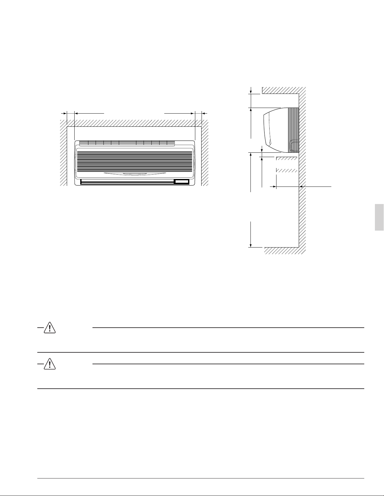
Where the wall is not signifi cantly tilted. •
Where piping between indoor and outdoor units is possible within the allowable limit. •
(Refer to the installation manual of the outdoor unit.)
Install the indoor and outdoor units, power supply wiring and connecting wires at least 3.5ft. away from •
televisions or radios in order to prevent image interference or noise.
(Depending on the radio waves, a distance of 3.5ft. may not be suffi cient enough to eliminate the noise.)
Where the cool (warm) air reaches all across the room. •
[ Space required for installation (in.) ]
≥ 2 ≥ 2
≥ 3 1/2
Obstruction
≥ 1 1/4
Fig. 1
Consider whether the place where the unit will be installed can support the full weight of the (2)
unit, and reinforce it with boards and beams, etc. if needed before proceeding with the installation. Also, reinforce the place to prevent vibration and noise before installing.
(The installation pitch can be found on the paper pattern for installation (3), so refer to it when
considering the necessity for reinforcing the location.)
The indoor unit may not be directly installed on the wall. Use the attached installation panel (1) (3)
before installing the unit.
DANGER
Do not install unit in an area where fl ammable materials are present due to risk of explosion resulting in •
serious injury or death.
≥ 100 (from floor)
For installation
in high places.
Floor
≤ 4 3/4
Fig. 2
WARNING
If the supporting structural members are not strong enough to take the unit's weight, the unit could fall •
out of place and cause serious injury.
6English
Page 8

INDOOR UNIT INSTALLATION4.
Use only accessories and parts which are of the designated specifi cation when installing. •
CAUTION
Install so that the unit does not tilt to either side or forward. •
Do not hold the unit by the horizontal fl aps when lifting it. (This may damage the horizontal fl aps.) •
Open the piping through-hole.(1)
The refrigerant pipe and drain pipe can be passed out in one of 5 directions: left, bottom-left, back-left, •
bottom-right, and back-right. (Refer to Fig. 3)
Using the paper pattern for installation (3), choose where to pass the piping out and open a through- •
hole (φ3 1/8”) in the wall.
Open the hole so that there is a downward slope for the drain piping. (See “ 6.DRAIN PIPING WORK ”)
Remove the installation panel (1) from the unit and attach to the wall.(2)
(The installation panel is temporarily attached to the unit with a screw. (In case of 12 type))
(Refer to Fig. 3)
(a) Check the location for the hole using the included paper pattern for installation (3).
Choose a location so that there is at least a 3 1/2” gap between the ceiling and the main unit. •
(b) Temporarily attach the installation panel (1) at the temporary-securing position on the paper pattern for
installation (3) and use a level to make sure the drain hose is either level or tilted slightly downward.
(c) Secure the installation panel (1) to the wall using either screws or bolts.
If using the attachment screws for the installation panel (2), attach using at least 4 screws on •
either side (for a total of 9 screws) of the recommended installation cleat position on the included
paper pattern for installation (3).
If using bolts, attach using a M8 - M10 bolt or equivalent (for a total of 2 bolts) on either side. •
If dealing with concrete, use commercially available foundation bolts (M8 - M10 or equivalent). •
If using the left, bottom-left, or bottom-right positions for the piping, cut out the through-hole for (3)
the piping in the front grill. (Refer to Fig. 4)
Installation panel (1)
Temporary screw
(In case of 12 type)
Fig. 3
Bottom-right pipe
Left pipe
Back-left pipe
Bottom-left pipe
Back-right pipe
Front grill
Cut out along
the groove.
Cut away
Fig. 4
7 English
Page 9

Remove the front panel and the service lid. (Refer to Fig. 5)(4)
< How to remove the front panel and service lid >
(1) Open the front panel to the point where it stops.
(2) Push the axes on either side of the front panel towards the center of the main unit and remove. (You
can also remove it by sliding the front panel either to the left or right and pulling it forward.)
(3) Remove the screw from the service lid and pull the handle forward.
Axis
(2) (2)
Axis
Point the pipe in the direction it will be passed out.(5)
For bottom-right and back-right piping (Refer to Fig. 6)
Wrap the drain hose and the refrigerant piping together with the insu- •
lating tape (4) so that the drain hose is below the refrigerant piping.
For left, bottom-left, and back-left piping
Remove the front grill. • (Refer to Fig. 7)
< How to remove the front grill >
Remove the front grill as described below when securing the indoor
unit with screws or when attaching Optional Accessories (wireless
remote controller, adapter PC board, etc.).
(1) Remove the front panel.
(1)
Front panel
Axis
Fig. 5
Service lid
(3)
Handle
Screw
Insulating tape (4)
Refrigerant piping
Drain hose
Fig. 6
(2) Remove the screws (3 places) securing the front grill.
(3) Remove the tabs (3 places) securing the front grill by pushing them in the direction of the arrows.
(4) Making sure not to catch the horizontal fl aps, remove the front grill by pulling in the direction of the arrow.
Ta b
(3)
Screw position
(2)
Tab position Tab position
(3) (3)
Front grill
(4)
(2) (2)
Fig. 7
Screw position
8English
Page 10

Remove the drain plug, the insulation tube, and the drain hose from the drain pan and replace. •
(Refer to Fig. 8)
Connect the local refrigerant piping ahead of time, matching it to the liquid pipe and gas pipe marks en- •
graved on the installation panel (accessory) (1).
< Replacing the drain hose and drain plug >
(1) Remove the drain plug and insulation tube.
(2) Remove the drain hose and replace onto the left side.
(3) Replace the drain plug and the insulation tube onto the right side.
Hook the indoor unit onto the installation panel. (Refer to Fig. 9)(6)
Placing buffering material between the wall and the indoor unit at this time will make work easier. •
Insulating tube
Make sure
there are
no gaps.
Fig. 8
Service lid
Front panel
Be sure to pass all wires through
the wiring guide.
Drain plug
Do not place lubricant (refrigerant oil) when inserting.
This may cause deterioration and water leaks.
Insert using a hexagon wrench (4mm).
Hook the indoor unit hook onto the installation panel (1).
Front grill
Place buffering material
Wall
Power supply wiring,
Ground wiring
Conduit
Refrigerant piping
(There are 2 places.)
Wiring (locally procured)
Transmission wiring, Remote controller wiring
For bottom-right and back-right piping
Pass the drain hose and the refrigerant piping to the wall. •
Pass power supply wiring and ground wiring threaded through conduit (For connecting the con-(7)
duit to the unit, see “8-1 HOW TO CONNECT WIRINGS”), and remote controller wiring through the
wiring guide in through the back of the indoor unit and to the front.
Ta b
Installation panel
(accessory) (1)
Fig. 9
9 English
Page 11

Connect the piping. (See “5.REFRIGERANT PIPING WORK” and Fig. 10)(8)
Drain hose
Transmission wiring
and remote controller
wiring
Secure with
vinyl tape.
Refrigerant piping
Conduit
A
A arrow view
Refrigerant piping
Transmission wiring and
remote controller wiring
Seal with putty corking material.
Fig. 10
Seal the piping through-hole with putty corking material. •
Push on both bottom edges of the indoor unit using both hands and hook the tab on the back of (9)
the indoor unit onto the installation panel (1). (Refer to Fig. 9)
At this time remove the buffering material placed in step (6). •
Make sure power supply wiring, transmission wiring, ground wiring and remote controller wiring are •
not caught inside the indoor unit.
When screwing in the indoor unit
Remove the front grill. • (Refer to Fig. 7)
Secure the indoor unit to the installation panel (1) with the securing •
screws (6). (Refer to Fig. 11)
Wrap the insulating tape overlapping at least half the width with each wrap.
Wrap the insulating tape all the way to the L-shaped bend.
Installation panel
(accessory) (1)
Refrigerant piping
Insulating tape
(accessory) (4)
M4 × 12L
Fig. 11
(accessory) (6)
REFRIGERANT PIPING WORK5.
For refrigerant piping of outdoor units, see the installation manual attached to the outdoor unit.〉
〈
Execute heat insulation work completely on both sides of the gas piping and the liquid piping.
〈
Otherwise, a water leakage can result sometimes.〉
(When using a heat pump, the temperature of the gas piping can reach up to approximately 250°F, so use
insulation which is suffi ciently resistant.)
Also, in cases where the temperature and humidity of the refrigerant piping sections might exceed
〈
86ºF or RH80 %, reinforce the refrigerant insulation. (13/16” or thicker) Condensation may form on
the surface of the insulating material.
Before refrigerant piping work, check which type of refrigerant is used. Proper operation is not
〈
possible if the types of refrigerant are not the same.
〉
〉
DANGER
Refrigerant gas may produce toxic gas if it comes in contact with fi re such as from a fan, heater, stove or •
cooking device. Exposure to this gas could result in severe injury or death.
10English
Page 12

NOTE
Use a pipe cutter and fl are suitable for the type of refrigerant. •
To prevent dust, moisture or other foreign matter from infi ltrating the tube, either pinch the end or cover it •
with tape.
Do not allow anything other than the designated refrigerant to get mixed into the refrigerant circuit, such •
as air, etc.
If any refrigerant gas leaks while working on the unit, ventilate the room thoroughly right away. •
The outdoor unit is charged with refrigerant. •
Torque wrench
Use copper alloy seamless pipes. •
Be sure to use both a spanner and torque wrench together, as shown •
in the drawing, when connecting or disconnecting pipes to/from the
unit. (Refer to Fig. 12)
Spanner
Refer to “Table 1” for the dimensions of fl are. •
When connecting the fl are nut, coat the fl are section with ester oil or •
ether oil, rotate three or four times fi rst, then screw in.
Piping union
Flare nut
(Refer to Fig. 13)
Fig. 12
CAUTION
Ester oil or ether oil
Over-tightening may cause the fl are nuts to crack or the refrigerant to •
leak.
Use the fl are nut included with the unit. •
Fig. 13
Refer to Table 1 for tightening torque. •
Table 1
Pipe size Tightening torque (ft-lbf) Flare dimensions A (in.) Flare shape (in.)
0
2
φ 3/8” 24.1 – 29.4 0.504 – 0.520
φ 5/8” 45.6 – 55.6 0.760 – 0.776
Ⳳ
0
45
0
2
Ⳳ
0
90
R0.016-0.031
A
Not recommended but in case of emergency
You must use a torque wrench but if you are obliged to install the unit without a torque wrench, you may
follow the installation method mentioned below.
After the work is fi nished, make sure to check that there is no gas leak.
When you keep on tightening the fl are nut with a spanner, there is a point where the tightening torque
suddenly increases. From that position, further tighten the fl are nut the angle shown below:
Table 2
Pipe size (in.) Further tightening angle Recommended arm length of tool (in.)
3/8” 60 to 90 degrees Approx. 7 7/8”
φ
5/8” 30 to 60 degrees Approx. 11 13/16”
φ
11 English
Page 13

CAUTION
CAUTION TO BE TAKEN WHEN BRAZING REFRIGERANT PIPING •
“Do not use fl ux when brazing refrigerant piping. Therefore, use the phosphor copper brazing fi lter metal
(BCuP) which does not require fl ux.”
(Flux has an extremely negative effect on refrigerant piping systems. For instance, if chlorine based fl ux
is used, it will cause pipe corrosion. If the fl ux contains fl uorine, it will damage the refrigerant oil.)
When brazing the refrigerant piping, only begin brazing after having carried out nitrogen substitution •
(NOTE 1) or while inserting nitrogen into the refrigerant piping (NOTE 2). Once this is done, connect the
indoor unit with a fl ared or a fl anged connection.
DANGER
Use of oxygen may cause an explosion resulting in serious injury or death. Only use nitrogen gas. •
NOTE
Refer to the “Manual for Multi Installation for Buildings” for directions on how to carry out nitrogen 1.
substitution. (Inquire with your dealer.)
Nitrogen should be set to 2.9 psi with a pressure-reducing valve if brazing while inserting nitrogen into 2.
the piping. (Refer to Fig. 14)
Pressure-reducing valve
Refrigerant piping
Part to be
brazed
Taping
hands valve
Nitrogen
After checking for gas leaks, be sure to insulate the pipe connections using the supplementary piping •
insulation tubing and insulating tape (4). The insulating tape (4) should be wrapped from the L-shaped
bend all the way to the end inside the unit. (Refer to Fig. 15)
Clamping material large
(accessory) (5)
Insulating tubing tape
Insulating tubing tape
Local piping
Nitrogen Fig. 14
Indoor unit piping insulation tubing
Insulating tubing tape
L-shaped
Indoor unit piping
Indoor unit piping insulation tubing
CAUTION
Be sure to insulate any fi eld piping all the way to the piping connection inside the unit. Any exposed piping •
may cause condensate or burns if touched.
Insulating tape (accessory) (4)
See “ 4.INDOOR UNIT
INSTALLATION ”
bend
Start wrapping
Insulation tubing seam
Attach the insulation tubing
tape so that there are no gaps
in the insulation tubing seam.
Fig. 15
12English
Page 14

DRAIN PIPING WORK6.
Install the drain piping. (Refer to Fig. 16)(1)
The drain pipe should be short with a downward slope and should prevent air pockets from forming. •
Watch out for the points in the fi gure 16 when performing drain work. •
Make sure the drain
hose is at a downward
slope.
Make sure the tip does
not go underwater even
when water is added.
When extending the drain hose, use a commercially available drain extension hose, and be sure to •
insulate the extended section of the drain hose which is indoors. (Refer to Fig. 17)
Extension drain piping
(commercially available)
Fig. 16
Drain hose Drain hose
(Downward
slope)
Indoor unit drain hose
Insulating tube
(commercially available)
Make sure the diameter of the extension drain piping is the same as the indoor unit drain hose (hard •
vinyl chloride, I.D. 9/16”) or bigger.
In case of converging multiple drain pipes, install them referring to Fig. 18. •
Select diameter of drain piping which adapts to the capacity of the unit connected. •
4 or more
Fig. 18
Make sure the drain works properly. (2)
After drain work is complete, perform a drain •
check by opening the front panel, removing
the air fi lter, pouring water into the drain pan,
and making sure water fl ows smoothly out of
the drain hose. (Refer to Fig. 19)
(Slope of at least 1/100)
Insulating tape (accessory) (4)
( See “4.INDOOR UNIT INSTALLATION” )
Plastic container
for pouring
Fig. 17
Drain pan
Fig. 19
13 English
Make sure not to splash the water.
Page 15

CAUTION
Drain piping connections •
Do not connect the drain piping directly to sewage pipes that smell of ammonia. The ammonia in the
sewage might enter the indoor unit through the drain pipes and corrode the heat exchanger.
Keep in mind that it will become the cause of getting drain pipe blocked if water collects on drain pipe.
ELECTRIC WIRING WORK7.
GENERAL INSTRUCTIONS7-1
All fi eld supplied parts and materials and electric works must conform to local codes. •
Use copper wire only. •
For electric wiring work, refer to also “WIRING DIAGRAM” attached to the unit. •
For remote controller wiring details, refer to the installation manual attached to the remote controller. •
All wiring must be performed by an authorized electrician. •
This system consists of multiple indoor units. Mark each indoor unit as unit A, unit B..., and be sure the •
terminal block wiring to the outdoor unit and BS unit is properly matched. If wiring and piping between the
outdoor unit and indoor unit are mismatched, the system may cause a malfunction.
A circuit breaker capable of shutting down power supply to the entire system must be installed. •
Refer to the installation manual attached to the outdoor unit for the size of power supply wiring connected •
to the outdoor unit, the capacity of the circuit breaker and switch, and wiring instructions.
Be sure to ground the air conditioner. •
DANGER
Do not ground units to water pipes, telephone wires or lightning rods because incomplete grounding •
could cause a severe shock hazard resulting in severe injury or death, and to gas pipes because a gas
leak could result in an explosion which could lead to severe injury or death.
ELECTRICAL CHARACTERISTICS7-2
Units Power supply Fan motor
Model Hz Volts Voltage range MCA MFA W FLA
FAQ18PVJU
FAQ24PVJU 0.6 15 43 0.5
MCA: Min. Circuit Amps (A); MFA: Max. Fuse Amps (A)
W: Fan Motor Rated Output (W); FLA: Full Load Amps (A)
60 208-230
Max. 253
Min. 187
0.4 15 43 0.3
SPECIFICATIONS FOR FIELD SUPPLIED FUSES AND WIRE7-3
Model
Field fuses
FAQ18PVJU
FAQ24PVJU
Allowable length of transmission wiring and remote controller wiring are as follows. •
(1) Outdoor unit - Indoor unit:Max.3280ft. (Total wiring length: 6560ft.)
(2) Indoor unit - Remote controller:Max.1640ft.
Insulated thickness: 1/16” or more. •
Power supply wiring
15A
Size must comply
with local codes.
Size Wire Size
Sheathed wire (2 wire)
Remote controller wiring
Transmission wiring
AWG18-16
14English
Page 16

WIRING EXAMPLE AND HOW TO SET THE REMOTE CONTROLLER8.
HOW TO CONNECT WIRINGS8-1
Conduit for power supply wiring •
Unscrew and remove the conduit mounting plate from the electric parts box. (Refer to Fig. 20)
Fix a conduit to the plate with a lock nut and reattach them at original position.
Conduit
Lock nut
Conduit mounting plate
Refrigerant piping
Electric parts box
Screw
Power supply wiring and ground wiring •
Unscrew and remove the service lid.
Thread the power supply wiring and ground wiring through the included insulating tube (short) (7) and
secure them with the included clamp (small) (5). (Refer to Fig. 21)
Connect the power supply wiring and ground wiring to the power supply terminal block (3P).
When doing this, fi rmly secure using the included clamp (small) (5) according to the fi gure.
(Refer to Fig. 22)
Transmission wiring and remote controller wiring •
Unscrew and remove the service lid.
Thread the remote controller wiring and transmission wiring through the included insulating tube (long) (7)
and secure them with the included clamp (small) (5). (Refer to Fig. 21)
Connect the remote controller wiring and the transmission wiring to the terminal block (6P).
When doing this, tie the remote controller wiring and the transmission wiring using the included clamp (small)
(5) and then fi rmly secure using the included clamp (small) (5) according to the fi gure. (Refer to Fig. 22)
Insulating tube (short)
(accessory) (7)
Fig. 21
Clamp small
(accessory) (5)
(1in.)
Insulating tube (long)
(accessory) (7)
Power
supply
wiring
Ground
wiring
Fig. 20
Clamp small
(accessory) (5)
(1in.)
Tramsmission
wiring
Remote
controller
wiring
15 English
Page 17

Power supply
terminal block (3P)
<
Wiring clamp method
Clamp small
(accessory) (5)
>
Ground terminal
Power supply wiring
Ground wiring
Ground wiring
Insulating tube
L1
L2
Remote controller
wiring
Transmission wiring
Clamp small
Power supply wiring
(accessory) (5)
Clamp small
Insulating tube
(accessory) (5)
Remote
controller wiring
REMOTE
CNTRL
F1 F2 T1 T2P1 P2
FORCED
TRANSMISSION
WIRING
OFF
(3 places)
Cut off any excess
material after tightening.
Terminal block (6P)
Transmission wiring
Fig. 22
WARNING
Never connect power supply wiring to the terminal block for remote controller wiring as this could dam- •
age the entire system.
Use only specifi ed wire and connect wires to the terminal tightly. Be careful wires do not place external •
stress on terminals. Keep wires in neat order so as not to obstruct other equipment. Make sure that the
electric box lid fi ts tightly. Incomplete connections could result in overheating and, in worse case, result in
electric shock or fi re.
To avoid a short circuit in the electric parts box, be sure to apply sealing material or putty (not included) •
to the wiring hole to prevent the infi ltration of water as well as insects or other small creatures. Otherwise
a short-circuit may occur inside the electric parts box.
CAUTION
When clamping the wirings, be sure no tension is applied to the wire connections by using the included •
clamp. Also, when wiring, make sure the lid on the electric parts box fi ts snugly by arranging the wirings neatly and attaching the service lid fi rmly. When attaching the service lid, make sure no wirings get
caught in the edges. Pass wiring through holes to prevent damage to them.
Make sure the remote controller wiring and transmission wiring between the units, and other electrical •
wiring do not pass through the same locations outside the unit, separating them by at least 5”, otherwise
electrical noise (external static) could cause incorrect operation or breakage.
Use only specifi ed wire and tightly connect wires to terminals. Be careful wires do not place external
stress on terminals. Keep wiring in neat order and so as not to obstruct other equipment such as popping
open the service cover. Make sure the cover closes tight. Incomplete connections could result in overheating, and in worse case, electric shock or fi re.
16English
Page 18

[ PRECAUTIONS ]
Use round crimp-style terminals for connecting wires to the power supply terminal block.1.
(Refer to Fig. 23)
If unavailable, observe the following points when wiring.
Do not connect wires of different gauge to the same power supply terminal. •
(Looseness in the connection may cause overheating.)
Use the specifi ed electric wire. Connect the wire securely to the terminal. Lock the wire down without •
applying excessive force to the terminal. (Tightening torque: 0.97ft.lbf ±10 %)
Attach insulation sleeve
Round crimp-style terminal
Electric wire
Fig. 23
Tightening torque for the terminal screws.2.
Use the correct screwdriver for tightening the terminal screws. If the blade of screwdriver is too small, •
the head of the screw might be damaged, and the screw will not be properly tightened.
If the terminal screws are tightened too hard, screws might be damaged. •
Refer to the table below for the tightening torque of the terminal screws. •
Terminal Size
Remote controller, Transmission wiring and
Forced off terminal block (6P)
M3.5 0.58 – 0.72
Tightening torque
(ft-lbf)
Power supply and Ground terminal block (3P) M4 0.87 – 1.06
Do not connect wires of different gauge to the same ground terminal. Looseness in the connection may 3.
lessen protection.
Keep transmission wiring at least 5” away from power supply wiring. The equipment may malfunction if 4.
subjected to electrical (external) noise.
For remote controller wiring, refer to the “INSTALLATION MANUAL OF REMOTE CONTROLLER” at-5.
tached to the remote controller.
WIRING EXAMPLE8-2
Fit the power supply wire of each unit with a switch and fuse as shown in the drawing. •
COMPLETE SYSTEM EXAMPLE
Power supply
Main
switch
Indoor unit
Remote controller
Outdoor unit
17 English
Power supply wire
Transmission wire
Switch
Fuse
Page 19

When using 1 remote controller for 1 indoor unit. (Normal operation)1.
Power Supply
208-230V
~
60Hz
L1L2
Outdoor unit
Control box
IN/D OUT/D
1 F2 F1 F2
F
P1P
2
F1F2T1T
L1L
2
2
Indoor unit
P1P
2
Remote
controller
When using 2 remote controllers for 1 indoor unit.2.
Power Supply
208-230V
~
60Hz
L1L2
Outdoor unit
Control box
IN/D OUT/D
1 F2 F1 F2
F
P1P2F1F2T1T
L1L
2
Indoor unit
P1P
2
For use with
2 remote
controllers
NOTE
A single switch can be used to supply power to units on the same system. However, branch switches 1.
and branch circuit breakers must be selected carefully.
Do not ground the equipment on gas pipes, water pipes or lightning rods, or crossground with tele-2.
phones. Improper grounding could result in electric shock.
2
P1P
2
18English
Page 20

CONTROL BY 2 REMOTE CONTROLLERS (CONTROLLING 1 INDOOR UNIT BY 8-3
2 REMOTE CONTROLLERS)
When using 2 remote controllers, one must be set to “MAIN” and the other to “SUB”. •
MAIN/SUB CHANGEOVER
Insert a (1) screwdriver into the recess between the
upper and lower part of remote controller, and
working from the 2 positions, pry off the upper part.
The remote controller PC board is attached to the
upper part of the remote controller. (Refer to Fig. 28)
Turn the (2) MAIN/SUB changeover switch on one of
the two remote controller PC boards to “S”.
(Leave the switch of the other remote controller set to
“M”.) (Refer to Fig. 29)
Wiring Method (See “7.ELECTRIC WIRING WORK”)
Remove the service lid.(3)
Add remote control 2 (slave) to the terminal block (4)
(6P) for remote controller (P1, P2) in the electric
parts box.
(There is no polarity.) (Refer to Fig. 26 and section
7-3 for the wiring size.)
Upper part of
remote controller
Lower part of
remote controller
Insert the screwdriver here
and gently work off the
upper part of the remote controller.
S
(Factory setting)
S
M
Remote
(Only one remote
controller needs
to be changed if
S
M
controller
PC board
factory settings
have remained
untouched.)
Fig. 28
Fig. 29
COMPUTERISED CONTROL (FORCED OFF AND ON/OFF OPERATION) 8-4
Wire specifi cations and how to perform wiring (1)
Connect the input from outside to terminals T1 and T2 of the terminal block (6P). •
Input A
F2 T1 T2
FORCED
OFF
Fig. 30
Actuation (2)
The following table explains FORCED OFF and ON/OFF OPERATIONS in response to Input A. •
FORCED OFF ON/OFF OPERATION
Input “ON” stops operation (impossible by remote controllers). Input OFF → ON turns ON unit.
Input OFF enables control by remote controller. Input ON → OFF turns OFF unit.
Wire specifi cation Sheathed vinyl cord or cable (2 wire)
Gauge AWG18-16
Length Max. 328 ft.
External terminal
Contact that can ensure the minimum
applicable load of 15V DC, 10 mA.
19 English
Page 21

How to select FORCED OFF and ON/OFF OPERATION (3)
Turn the power on and then use the remote controller to •
SECOND CODE NO.
Mode No.
select operation.
Set the remote controller to the fi eld set mode. For details, •
refer to the “HOW TO SET IN THE FIELD”, in the remote
controller manual.
When in the fi eld set mode, select mode No. 12, then set •
the fi rst code (switch) No. to “1”. Then set second code
SETTING
(position) No. to “01” for FORCED OFF and “02” for ON/
OFF OPERATION.
(FORCED OFF at factory set) (Refer to Fig. 31)
FIRST CODE NO.
FIELD SET MODE
Fig. 31
CENTRALIZED CONTROL 8-5
For centralized control, it is necessary to designate the group No. For details, refer to the manual of each •
optional controllers for centralized control.
FIELD SETTINGS9.
Make sure the service lids are closed on the indoor and outdoor units.(1)
Field settings must be made from the remote controller in accordance with installation conditions.(2)
Settings can be made by changing the “Mode No”, “FIRST CODE NO.” and “SECOND CODE NO.”. •
Refer to the installation manual attached to the remote controller.
The “Field Settings” included with the remote controller lists the order of the settings and method of op- •
eration.
* Setting is made in all units in a group. To set for individual indoor units or to check the setting, use the
mode Nos. (with “2” in upper digit) in parentheses ( ).
SETTING AIR FILTER SIGN9-1
Remote controllers are equiped with liquid crystal display air fi lter signs to display the time to clean air fi lters. •
Change the SECOND CODE NO. according to Table 3 depending on the amount of dirt or dust in the room. •
(SECOND CODE NO. is factory set to “01” for air fi lter contamination-light)
Table 3
Setting
Air fi lter
contamination-light
Air fi lter
contamination-heavy
Spacing time of display
air fi lter sign
Mode No. FIRST CODE NO. SECOND CODE NO.
Approx. 200 hrs
10 (20) 0
Approx. 100 hrs 02
01
20English
Page 22

SETTING AIR FLOWRATE INCREASE MODE9-2
It is possible to raise set air fl ow (HIGH and LOW) from the fi eld. Change the SECOND CODE NO. as •
shown in Table 4 to suit your needs.
(SECOND CODE NO. is factory set to “01” for Standard.)
Table 4
Setting Mode No. FIRST CODE NO. SECOND CODE NO.
Standard
A little increase 02
Increase 03
When using wireless remote controllers
〈
When using wireless remote controllers, wireless remote controller address setting is necessary. Refer to •
the installation manual attached to the wireless remote controller for setting instructions.
13 (23) 0
〉
01
TEST OPERATION10.
Make sure the service lids are closed on the indoor and outdoor units.
Refer to the installation manual of the outdoor unit.
The operation lamp of the remote controller will fl ash when a malfunction occurs. Check the malfunction •
code on the liquid crystal display to identify the point of trouble. An explanation of malfunction codes and
the corresponding trouble is provided in the installation manual of the outdoor unit.
If any of the items in Table 5 are displayed, there may be a problem with the wiring or power, so check
the wiring again.
Table 5
Remote controller display Content
“
control) is lit up
“U4” is lit up
“UH” is lit up
No display
If “U3” is lit up, the malfunction code shows the test operation has not been performed yet. •
” (under centralized
There is a short circuit at the FORCED OFF terminals (T1, T2). •
The power on the outdoor unit is off. •
The outdoor unit has not been wired for power supply. •
Incorrect wiring for the transmission wiring and/or FORCED •
OFF wiring.
The transmission wiring is cut. •
The power on the indoor unit is off. •
The indoor unit has not been wired for power supply. •
Incorrect wiring for the remote controller wiring, the •
transmission wiring, and/or the FORCED OFF wiring.
The remote controller wiring is cut. •
21 English
Page 23

(0902)
EM08A091A3PN07521-2C
FS
 Loading...