

Installation and operation manual
Split system air conditioner
FAA71BUV1B
FAA100BUV1B
Installation and operation manual
Split system air conditioner
English
Directivelor, cu amendamentele respective.
<A>
<B>
<C>
DEKRA (NB0344)
2178265.0551-EMC
DAIKIN.TCF.033B2/06-2021
Direktive z vsemi spremembami.
Direktiivid koos muudatustega.
Директиви, с техните изменения.
Direktyvose su papildymais.
Direktīvās un to papildinājumos.
Smernice, v platnom znení.
18192021222324
Direktiver, med senere ændringer.
Direktiv, med företagna ändringar.
Direktiver, med foretatte endringer.
10111213141516
deklaruje na własną i wyłączną odpowiedzialność, że modele klimatyzatorów, których dotyczy niniejsza deklaracja:
declară pe proprie răspundere că aparatele de aer condiţionat la care se referă această declaraţie:
z vso odgovornostjo izjavlja, da so modeli klimatskih naprav, na katere se izjava nanaša:
kinnitab oma täielikul vastutusel, et käesoleva deklaratsiooni alla kuuluvad kliimaseadmete mudelid:
декларира на своя отговорност, че моделите климатична инсталация, за които се отнася тази декларация:
visiška savo atsakomybe skelbia, kad oro kondicionavimo prietaisų modeliai, kuriems yra taikoma ši deklaracija:
ar pilnu atbildību apliecina, ka tālāk uzskaitīto modeļu gaisa kondicionētāji, uz kuriem attiecas šī deklarācija:
vyhlasuje na vlastnú zodpovednosť, že tieto klimatizačné modely, na ktoré sa vzťahuje toto vyhlásenie:
tamamen kendi sorumluluǧunda olmak üzere bu bildirinin ilgili olduǧu klima modellerinin aşaǧıdaki gibi olduǧunu beyan eder:
17
18
19
20
21
22
23
24
25
megfelelnek az alábbi szabvány(ok)nak vagy egyéb irányadó dokumentum(ok)nak, ha azokat előírás szerint használják:
spełniają wymogi następujących norm i innych dokumentów normalizacyjnych, pod warunkiem że używane są zgodnie z naszymi instrukcjami:
sunt în conformitate cu următorul (următoarele) standard(e) sau alt(e) document(e) normativ(e), cu condiţia ca acestea să fie utilizate în conformitate cu
instrucţiunile noastre:
skladni z naslednjimi standardi in drugimi normativi, pod pogojem, da se uporabljajo v skladu z našimi navodili:
on vastavuses järgmis(t)e standardi(te)ga või teiste normatiivsete dokumentidega, kui neid kasutatakse vastavalt meie juhenditele:
съответстват на следните стандарти или други нормативни документи, при условие, че се използват съгласно нашите инструкции:
atitinka žemiau nurodytus standartus ir (arba) kitus norminius dokumentus su sąlyga, kad yra naudojami pagal mūsų nurodymus:
tad, ja lietoti atbilstoši ražotāja norādījumiem, atbilst sekojošiem standartiem un citiem normatīviem dokumentiem:
sú v zhode s nasledovnou(ými) normou(ami) alebo iným(i) normatívnym(i) dokumentom(ami), za predpokladu, že sa používajú v súlade snašim
161718192021222324
návodom:
Directives, as amended.
Direktiven, gemäß Änderung.
ürünün, talimatlarımıza göre kullanılması koşuluyla aşağıdaki standartlar ve norm belirten belgelerle uyumludur:
25
Directives, telles que modifiées.
010203040506070809
Değiştirilmiş halleriyle Yönetmelikler.
25
Direktiivejä, sellaisina kuin ne ovat muutettuina.
v platném znění.
Smjernice, kako je izmijenjeno.
irányelv(ek) és módosításaik rendelkezéseit.
z późniejszymi poprawkami.
17
както е изложено в <A> и оценено положително от <B>
съгласно Сертификата<C>.
kaip nustatyta <A> ir kaip teigiamai nuspręsta <B> pagal
Sertifikatą<C>.
kā norādīts <A> un atbilstoši <B> pozitīvajam vērtējumam
saskaņā ar sertifikātu<C>.
Richtlijnen, zoals geamendeerd.
Directivas, según lo enmendado.
Direttive, come da modifica.
Οδηγιών, όπως έχουν τροποποιηθεί.
Directivas, conforme alteração em.
Директив со всеми поправками.
21Забележка*
22Pastaba*
23Piezīmes*
*
**
Daikin Europe N.V. je pooblaščen za sestavo datoteke s tehnično mapo.
Daikin Europe N.V. on volitatud koostama tehnilist dokumentatsiooni.
Daikin Europe N.V. е оторизирана да състави Акта за техническа конструкция.
Daikin Europe N.V. yra įgaliota sudaryti šį techninės konstrukcijos failą.
Daikin Europe N.V. ir autorizēts sastādīt tehnisko dokumentāciju.
Spoločnosť Daikin Europe N.V. je oprávnená vytvoriť súbor technickej konštrukcie.
Daikin Europe N.V. Teknik Yapı Dosyasını derlemeye yetkilidir.
19**
20**
21**
22**
23**
24**
25**
ako bolo uvedené v <A> a pozitívne zistené <B> vsúlade
s osvedčením<C>.
<A>’da belirtildiği gibi ve <C>Sertifikasına göre <B>
tarafından olumlu olarak değerlendirildiği gibi.
24Poznámka*
25Not*
a(z) <A> alapján, a(z) <B> igazolta a megfelelést, a(z)
<C>tanúsítvány szerint.
zgodnie z dokumentacją <A>, pozytywną
opinią <B> i Świadectwem<C>.
aşa cum este stabilit în <A> şi apreciat pozitiv de<B>
în conformitate cu Certificatul<C>.
kot je določeno v <A> in odobreno s strani <B>
vskladu scertifikatom<C>.
nagu on näidatud dokumendis <A> ja heaks kiidetud
<B> järgi vastavalt sertifikaadile<C>.
Daikin Europe N.V. on valtuutettu laatimaan Teknisen asiakirjan.
Společnost Daikin Europe N.V. má oprávnění ke kompilaci souboru technické konstrukce.
Daikin Europe N.V. je ovlašten za izradu Datoteke o tehničkoj konstrukciji.
A Daikin Europe N.V. jogosult a műszaki konstrukciós dokumentáció összeállítására.
Daikin Europe N.V. ma upoważnienie do zbierania i opracowywania dokumentacji konstrukcyjnej.
Daikin Europe N.V. este autorizat să compileze Dosarul tehnic de construcţie.
13**
14**
15**
16**
17**
16Megjegyzés*
17Uwaga*
18Notă*
19Opomba*
20Märkus*
Machinery 2006/42/EC
Low Voltage 2014/35/EU
enligt <A> och godkänts av <B> enligt
Certifikatet<C>.
som det fremkommer i <A> og gjennom positiv
bedømmelse av <B> ifølge Sertifikat<C>.
jotka on esitetty asiakirjassa <A> ja jotka <B>
on hyväksynyt Sertifikaatin<C> mukaisesti.
jak bylo uvedeno v <A> a pozitivně zjištěno
<B> vsouladu sosvědčením<C>.
kako je izloženo u <A> i pozitivno ocijenjeno odstrane
Electromagnetic Compatibility 2014/30/EU
заявляет, исключительно под свою ответственность, что модели кондиционеров воздуха, к которым относится настоящее заявление:
erklærer under eneansvar, at klimaanlægmodellerne, som denne deklaration vedrører:
deklarerar i egenskap av huvudansvarig, att luftkonditioneringsmodellerna som berörs av denna deklaration innebär att:
erklærer et fullstendig ansvar for at de luftkondisjoneringsmodeller som berøres av denne deklarasjon, innebærer at:
ilmoittaa yksinomaan omalla vastuullaan, että tämän ilmoituksen tarkoittamat ilmastointilaitteiden mallit:
prohlašuje ve své plné odpovědnosti, že modely klimatizace, k nimž se toto prohlášení vztahuje:
izjavljuje pod isključivo vlastitom odgovornošću da su modeli klima uređaja na koje se ova izjava odnosi:
teljes felelőssége tudatában kijelenti, hogy a klímaberendezés modellek, melyekre e nyilatkozat vonatkozik:
09
10
11
12
13
14
15
16
estão em conformidade com a(s) seguinte(s) norma(s) ou outro(s) documento(s) normativo(s), desde que estes sejam utilizados de
acordo com as nossas instruções:
соответствуют следующим стандартам или другим нормативным документам, при условии их использования согласно нашим инструкциям:
overholder følgende standard(er) eller andet/andre retningsgivende dokument(er), forudsat at disse anvendes i henhold til vore instrukser:
respektive utrustning är utförd i överensstämmelse med och följer följande standard(er) eller andra normgivande dokument, under förutsättning att
användning sker i överensstämmelse med våra instruktioner:
respektive utstyr er i overensstemmelse med følgende standard(er) eller andre normgivende dokument(er), under forutssetning av at disse brukes i
henhold til våre instrukser:
vastaavat seuraavien standardien ja muiden ohjeellisten dokumenttien vaatimuksia edellyttäen, että niitä käytetään ohjeidemme mukaisesti:
za předpokladu, že jsou využívány v souladu s našimi pokyny, odpovídají následujícím normám nebo normativním dokumentům:
08091011121314
u skladu sa slijedećim standardom(ima) ili drugim normativnim dokumentom(ima), uz uvjet da se oni koriste u skladu s našim uputama:
15
ob upoštevanju določb:
vastavalt nõuetele:
следвайки клаузите на:
laikantis nuostatų, pateikiamų:
ievērojot prasības, kas noteiktas:
19202122232425
održiavajúc ustanovenia:
11Information*
12Merk*
13Huom*
bunun koşullarına uygun olarak:
delineato nel <A> e giudicato positivamente da<B>
secondo il Certificato<C>.
όπως καθορίζεται στο <A> και κρίνεται θετικά
από το <B> σύμφωνα με το Πιστοποιητικό<C>.
tal como estabelecido em <A> e com o parecer positivo
<B> prema Certifikatu<C>.
14Poznámka*
15Napomena*
Η Daikin Europe N.V. είναι εξουσιοδοτημένη να συντάξει τον Τεχνικό φάκελο κατασκευής.
07**
de <B> de acordo com o Certificado<C>.
как указано в <A> и в соответствии сположительным
решением <B> согласно Свидетельству<C>.
som anført i <A> og positivt vurderet af <B> ihenhold til
Certifikat<C>.
18**
A Daikin Europe N.V. está autorizada a compilar a documentação técnica de fabrico.
Компания Daikin Europe N.V. уполномочена составить Комплект технической документации.
Daikin Europe N.V. er autoriseret til at udarbejde de tekniske konstruktionsdata.
Daikin Europe N.V. är bemyndigade att sammanställa den tekniska konstruktionsfilen.
Daikin Europe N.V. har tillatelse til å kompilere den Tekniske konstruksjonsfilen.
08**
09**
10**
11**
12**
Hiromitsu Iwasaki
Director
Ostend, 1st of July 2021
declares under its sole responsibility that the air conditioning models to which this declaration relates:
erklärt auf seine alleinige Verantwortung daß die Modelle der Klimageräte für die diese Erklärung bestimmt ist:
CE - DECLARATION-OF-CONFORMITY CE - DECLARACION-DE-CONFORMIDAD CE - DECLARAÇÃO-DE-CONFORMIDADE CE - ERKLÆRING OM-SAMSVAR CE - IZJAVA-O-USKLAĐENOSTI CE - IZJAVA O SKLADNOSTI CE - ATITIKTIES-DEKLARACIJA
CE - KONFORMITÄTSERKLÄRUNG CE - DICHIARAZIONE-DI-CONFORMITA CE - ЗАЯВЛЕНИЕ-О-СООТВЕТСТВИИ CE - ILMOITUS-YHDENMUKAISUUDESTA CE - MEGFELELŐSÉGI-NYILATKOZAT CE - VASTAVUSDEKLARATSIOON CE - ATBILSTĪBAS-DEKLARĀCIJA
CE - DECLARATION-DE-CONFORMITE CE - ΔHΛΩΣΗ ΣΥΜΜΟΡΦΩΣΗΣ CE - OVERENSSTEMMELSESERKLÆRING CE - PROHLÁŠENÍ-O-SHODĚ CE - DEKLARACJA-ZGODNOŚCI CE - ДЕКЛАРАЦИЯ-ЗА-СЪОТВЕТСТВИЕ CE - VYHLÁSENIE-ZHODY
CE - CONFORMITEITSVERKLARING CE - FÖRSÄKRAN-OM-ÖVERENSTÄMMELSE CE - DECLARAŢIE-DE-CONFORMITATE CE - UYGUNLUK-BEYANI
déclare sous sa seule responsabilité que les appareils d'air conditionné visés par la présente déclaration:
Daikin Europe N.V.
01
02
03
06Nota*
07Σημείωση*
08Nota*
09Примечание*
10Bemærk*
under iagttagelse af bestemmelserne i:
enligt villkoren i:
gitt i henhold til bestemmelsene i:
noudattaen määräyksiä:
za dodržení ustanovení předpisu:
prema odredbama:
követi a(z):
zgodnie z postanowieniami Dyrektyw:
101112131415161718
verklaart hierbij op eigen exclusieve verantwoordelijkheid dat de airconditioning units waarop deze verklaring betrekking heeft:
declara baja su única responsabilidad que los modelos de aire acondicionado a los cuales hace referencia la declaración:
dichiara sotto sua responsabilità che i condizionatori modello a cui è riferita questa dichiarazione:
δηλώνει με αποκλειστική της ευθύνη ότι τα μοντέλα των κλιματιστικών συσκευών στα οποία αναφέρεται η παρούσα δήλωση:
declara sob sua exclusiva responsabilidade que os modelos de ar condicionado a que esta declaração se refere:
04
05
06
FAA71BUV1B, FAA100BUV1B,
07
08
are in conformity with the following standard(s) or other normative document(s), provided that these are used in accordance with our instructions:
der/den folgenden Norm(en) oder einem anderen Normdokument oder -dokumenten entspricht/entsprechen, unter der Voraussetzung, daß sie gemäß
unseren Anweisungen eingesetzt werden:
sont conformes à la/aux norme(s) ou autre(s) document(s) normatif(s), pour autant qu'ils soient utilisés conformément à nos instructions:
conform de volgende norm(en) of één of meer andere bindende documenten zijn, op voorwaarde dat ze worden gebruikt overeenkomstig onze
instructies:
están en conformidad con la(s) siguiente(s) norma(s) u otro(s) documento(s) normativo(s), siempre que sean utilizados de acuerdo con nuestras
instrucciones:
sono conformi al(i) seguente(i) standard(s) o altro(i) documento(i) a carattere normativo, a patto che vengano usati in conformità alle nostre istruzioni:
είναι σύμφωνα με το(α) ακόλουθο(α) πρότυπο(α) ή άλλο έγγραφο(α) κανονισμών, υπό την προϋπόθεση ότι χρησιμοποιούνται
01020304050607
σύμφωνα με τις οδηγίες μας:
following the provisions of:
gemäß den Vorschriften der:
conformément aux stipulations des:
EN60335-2-40,
overeenkomstig de bepalingen van:
010203040506070809
în urma prevederilor:
as set out in <A> and judged positively by <B>
according to the Certificate<C>.
wie in <A> aufgeführt und von <B> positiv
beurteilt gemäß Zertifikat<C>.
tel que défini dans <A> et évalué positivement par <B>
conformément au Certificat<C>.
zoals vermeld in <A> en positief beoordeeld door <B>
siguiendo las disposiciones de:
secondo le prescrizioni per:
με τήρηση των διατάξεων των:
de acordo com o previsto em:
в соответствии с положениями:
01Note*
02Hinweis*
03Remarque*
04Bemerk*
overeenkomstig Certificaat<C>.
como se establece en <A> y es valorado
positivamente por <B> de acuerdo con el
Certificado<C>.
05Nota*
Daikin Europe N.V. is authorised to compile the Technical Construction File.
Daikin Europe N.V. hat die Berechtigung die Technische Konstruktionsakte zusammenzustellen.
01**
02**
Daikin Europe N.V. est autorisé à compiler le Dossier de Construction Technique.
Daikin Europe N.V. is bevoegd om het Technisch Constructiedossier samen te stellen.
Daikin Europe N.V. está autorizado a compilar el Archivo de Construcción Técnica.
Daikin Europe N.V. è autorizzata a redigere il File Tecnico di Costruzione.
03**
04**
05**
06**
3P471028-18M

Table of Contents
Table of Contents
1 About the documentation 3
1.1 About this document.................................................................. 3
2 Specific installer safety instructions 4
For the user 4
3 User safety instructions 4
3.1 General...................................................................................... 4
3.2 Instructions for safe operation ................................................... 5
4 About the system 7
4.1 System layout............................................................................ 7
5 User interface 8
6 Operation 8
6.1 Operation range ........................................................................ 8
6.2 About operation modes ............................................................. 8
6.2.1 Basic operation modes ............................................... 8
6.2.2 Special heating operation modes................................ 9
6.2.3 Airflow direction........................................................... 9
6.3 To operate the system............................................................... 9
7 Maintenance and service 10
7.1 Precautions for maintenance and service ................................. 10
7.2 Cleaning the unit ....................................................................... 10
7.2.1 To clean the air outlet and exterior ............................. 10
7.2.2 To clean the front panel .............................................. 10
7.2.3 To clean the air filter ................................................... 11
7.3 About the refrigerant.................................................................. 11
8 Troubleshooting 11
9 Relocation 12
10 Disposal 12
For the installer 12
11 About the box 12
11.1 Indoor unit ................................................................................. 12
11.1.1 To remove the accessories from the indoor unit......... 12
12 Unit installation 12
12.1 Preparing the installation site .................................................... 12
12.1.1 Installation site requirements of the indoor unit .......... 12
12.2 Mounting the indoor unit............................................................ 13
12.2.1 To install the mounting plate....................................... 13
12.2.2 To drill a wall hole ....................................................... 14
12.2.3 To remove the pipe port cover.................................... 14
12.2.4 To hook the unit on the mounting plate....................... 15
12.2.5 To pass the pipes through the wall hole ..................... 15
12.2.6 To provide drainage.................................................... 15
13 Piping installation 16
13.1 Preparing refrigerant piping....................................................... 16
13.1.1 Refrigerant piping requirements.................................. 16
13.1.2 Refrigerant piping insulation ....................................... 16
13.2 Connecting the refrigerant piping .............................................. 17
13.2.1 To connect the refrigerant piping to the indoor unit .... 17
15.1 To fix the unit on the mounting plate .......................................... 19
16 Commissioning 19
16.1 Checklist before commissioning................................................. 19
16.2 To perform a test run.................................................................. 20
17 Configuration 20
17.1 Field setting ................................................................................ 20
18 Technical data 21
18.1 Wiring diagram ........................................................................... 21
18.1.1 Unified wiring diagram legend...................................... 21
1 About the documentation
1.1 About this document
Target audience
Authorised installers + end users
INFORMATION
This appliance is intended to be used by expert or trained
users in shops, in light industry, and on farms, or for
commercial and household use by lay persons.
WARNING
Make sure installation, servicing, maintenance, repair and
applied materials follow the instructions from Daikin and, in
addition, comply with applicable legislation and are
performed by qualified persons only. In Europe and areas
where IEC standards apply, EN/IEC 60335-2-40 is the
applicable standard.
Documentation set
This document is part of a documentation set. The complete set
consists of:
▪ General safety precautions:
▪ Safety instructions that you must read before installing
▪ Format: Paper (in the box of the indoor unit)
▪ Indoor unit installation and operation manual:
▪ Installation and operation instructions
▪ Format: Paper (in the box of the indoor unit)
▪ Installer and user reference guide:
▪ Preparation of the installation, good practices, reference data,…
▪ Detailed step-by-step instructions and background information
for basic and advanced usage
▪ Format: Digital files on http://www.daikineurope.com/support-
and-manuals/product-information/
Latest revisions of the supplied documentation may be available on
the regional Daikin website or via your dealer.
The original documentation is written in English. All other languages
are translations.
Technical engineering data
▪ A subset of the latest technical data is available on the regional
Daikin website (publicly accessible).
▪ The full set of latest technical data is available on the Daikin
Business Portal (authentication required).
14 Electrical installation 17
14.1 Specifications of standard wiring components .......................... 17
14.2 To connect the electrical wiring to the indoor unit ..................... 17
15 Finishing the indoor unit installation 19
FAA71+100BUV1B
Split system air conditioner
3P654518-1A – 2021.03
Installation and operation manual
3
2 Specific installer safety instructions
2 Specific installer safety
instructions
Always observe the following safety instructions and regulations.
General
WARNING
Make sure installation, servicing, maintenance, repair and
applied materials follow the instructions from Daikin and, in
addition, comply with applicable legislation and are
performed by qualified persons only. In Europe and areas
where IEC standards apply, EN/IEC 60335-2-40 is the
applicable standard.
Unit installation (see "12Unit installation"[412])
WARNING
The appliance using R32 refrigerant shall be stored so as
to prevent mechanical damage and in a well-ventilated
room without continuously operating ignition sources (e.g.
open flames, an operating gas appliance, or an operating
electric heater). The room size shall be as specified in the
General safety precaution.
CAUTION
For walls containing a metal frame or a metal board, use a
wall embedded pipe and wall cover in the feed-through
hole to prevent possible heat, electrical shock, or fire.
Refrigerant piping installation (see "13Piping
installation"[416])
CAUTION
Piping MUST be installed according to instructions given in
"13Piping installation"[416]. Only mechanical joints (e.g.
braze+flare connections) that are compliant with the latest
version of ISO14903 can be used.
CAUTION
▪ Do NOT use mineral oil on flared part.
▪ Do NOT reuse piping from previous installations.
▪ NEVER install a drier to this unit to guarantee its
lifetime. The drying material may dissolve and damage
the system.
CAUTION
▪ Incomplete flaring may cause refrigerant gas leakage.
▪ Do NOT re-use flares. Use new flares to prevent
refrigerant gas leakage.
▪ Use flare nuts that are included with the unit. Using
different flare nuts may cause refrigerant gas leakage.
CAUTION
Install the refrigerant piping or components in a position
where they are unlikely to be exposed to any substance
which may corrode components containing refrigerant,
unless the components are constructed of materials that
are inherently resistant to corrosion or are suitably
protected against corrosion.
Electrical installation (see "14Electrical installation"[417])
WARNING
▪ All wiring MUST be performed by an authorised
electrician and MUST comply with the applicable
legislation.
▪ Make electrical connections to the fixed wiring.
▪ All components procured on-site and all electrical
construction MUST comply with the applicable
legislation.
WARNING
▪ If the power supply has a missing or wrong N-phase,
equipment might break down.
▪ Establish proper earthing. Do NOT earth the unit to a
utility pipe, surge absorber, or telephone earth.
Incomplete earthing may cause electrical shock.
▪ Install the required fuses or circuit breakers.
▪ Secure the electrical wiring with cable ties so that the
cables do NOT come in contact with sharp edges or
piping, particularly on the high-pressure side.
▪ Do NOT use taped wires, stranded conductor wires,
extension cords, or connections from a star system.
They can cause overheating, electrical shock or fire.
▪ Do NOT install a phase advancing capacitor, because
this unit is equipped with an inverter. A phase
advancing capacitor will reduce performance and may
cause accidents.
WARNING
ALWAYS use multicore cable for power supply cables.
WARNING
Use an all-pole disconnection type breaker with at least
3 mm between the contact point gaps that provide full
disconnection under overvoltage category III.
WARNING
If the supply cord is damaged, it MUST be replaced by the
manufacturer, its service agent or similarly qualified
persons in order to avoid a hazard.
For the user
3 User safety instructions
Always observe the following safety instructions and regulations.
Installation and operation manual
4
3.1 General
WARNING
If you are NOT sure how to operate the
unit, contact your installer.
FAA71+100BUV1B
Split system air conditioner
3P654518-1A – 2021.03
3 User safety instructions
WARNING
This appliance can be used by children
aged from 8 years and above and
persons with reduced physical, sensory
or mental capabilities or lack of
experience and knowledge if they have
been given supervision or instruction
concerning use of the appliance in a
safe way and understand the hazards
involved.
Children SHALL NOT play with the
appliance.
Cleaning and user maintenance
SHALL NOT be made by children
without supervision.
WARNING
To prevent electrical shocks or fire:
▪ Do NOT rinse the unit.
▪ Do NOT operate the unit with wet
hands.
▪ Do NOT place any objects containing
water on the unit.
CAUTION
▪ Do NOT place any objects or
equipment on top of the unit.
▪ Do NOT sit, climb or stand on the
unit.
▪ Units are marked with the following symbol:
▪ Batteries are marked with the following symbol:
This means that the batteries may NOT be mixed with unsorted
household waste. If a chemical symbol is printed beneath the
symbol, this chemical symbol means that the battery contains a
heavy metal above a certain concentration.
Possible chemical symbols are: Pb: lead (>0.004%).
Waste batteries must be treated at a specialized treatment facility
for reuse. By ensuring waste batteries are disposed of correctly,
you will help to prevent potential negative consequences for the
environment and human health.
3.2 Instructions for safe operation
WARNING
▪ Do NOT modify, disassemble,
remove, reinstall or repair the unit
yourself as incorrect dismantling or
installation may cause an electric
shock or fire. Contact your dealer.
▪ In case of accidental refrigerant
leaks, make sure there are no naked
flames. The refrigerant itself is
entirely safe and non-toxic. R410A is
a non-combustible refrigerant, and
R32 is a mildly flammable refrigerant,
but they will generate a toxic gas
when they accidentally leak into a
room where combustible air from fan
heaters, gas cookers, etc. is present.
Always have qualified service
personnel confirm that the point of
leakage has been repaired or
corrected before resuming operation.
This means that electrical and electronic products may NOT be
mixed with unsorted household waste. Do NOT try to dismantle
the system yourself: the dismantling of the system, treatment of
the refrigerant, of oil and of other parts must be done by an
authorized installer and must comply with applicable legislation.
Units must be treated at a specialized treatment facility for reuse,
recycling and recovery. By ensuring this product is disposed of
correctly, you will help to prevent potential negative consequences
for the environment and human health. For more information,
contact your installer or local authority.
FAA71+100BUV1B
Split system air conditioner
3P654518-1A – 2021.03
CAUTION
▪ NEVER touch the internal parts of the
controller.
▪ Do NOT remove the front panel.
Some parts inside are dangerous to
touch and appliance problems may
happen. For checking and adjusting
the internal parts, contact your
dealer.
WARNING
This unit contains electrical and hot
parts.
Installation and operation manual
5
3 User safety instructions
WARNING
Before operating the unit, be sure the
installation has been carried out
correctly by an installer.
CAUTION
It is unhealthy to expose your body to
the air flow for a long time.
CAUTION
To avoid oxygen deficiency, ventilate
the room sufficiently if equipment with
burner is used together with the
system.
CAUTION
Do NOT operate the system when
using a room fumigation-type
insecticide. Chemicals could collect in
the unit, and endanger the health of
people who are hypersensitive to
chemicals.
CAUTION
CAUTION
Do NOT insert fingers, rods or other
objects into the air inlet or outlet. When
the fan is rotating at high speed, it will
cause injury.
WARNING
NEVER replace a fuse with a fuse of a
wrong ampere ratings or other wires
when a fuse blows out. Use of wire or
copper wire may cause the unit to
break down or cause a fire.
CAUTION
After a long use, check the unit stand
and fitting for damage. If damaged, the
unit may fall and result in injury.
CAUTION
Before accessing terminal devices,
make sure to interrupt all power supply.
DANGER: RISK OF
ELECTROCUTION
▪ ALWAYS use a user interface to
adjust the angle of the flap. When the
flap is swinging and you move it
forcibly by hand, the mechanism will
break.
▪ Be careful when adjusting the
louvers. Inside the air outlet, a fan is
rotating at high speed.
CAUTION
NEVER expose little children, plants or
animals directly to the airflow.
WARNING
Do NOT place a flammable spray
bottle near the air conditioner and do
NOT use sprays near the unit. Doing
so may result in a fire.
Maintenance and service (see "7Maintenance and
service"[410])
CAUTION: Pay attention to the fan!
It is dangerous to inspect the unit while
the fan is running.
Be sure to turn off the main switch
before executing any maintenance
task.
To clean the air conditioner or air filter,
be sure to stop operation and turn all
power supplies off. Otherwise, an
electric shock and injury may result.
WARNING
Be careful with ladders when working
in high places.
CAUTION
Turn off the unit before cleaning the air
outlet, exterior, front panel and air filter.
WARNING
Do NOT let the indoor unit get wet.
Possible consequence: Electric
shock or fire.
About the refrigerant (see "7.3About the refrigerant"[411])
WARNING: MILDLY FLAMMABLE
MATERIAL
The R32 refrigerant (if applicable) in
this unit is mildly flammable. Refer to
the outdoor unit specifications for the
type of refrigerant to be used.
Installation and operation manual
6
FAA71+100BUV1B
Split system air conditioner
3P654518-1A – 2021.03
4 About the system
b
c
a
d
e
WARNING
The appliance using R32 refrigerant
shall be stored so as to prevent
mechanical damage and in a wellventilated room without continuously
operating ignition sources (e.g. open
flames, an operating gas appliance, or
an operating electric heater). The room
size shall be as specified in the
General safety precaution.
WARNING
▪ Do NOT pierce or burn refrigerant
cycle parts.
▪ Do NOT use cleaning materials or
means to accelerate the defrosting
process other than those
recommended by the manufacturer.
▪ Be aware that the refrigerant inside
the system is odourless.
WARNING
R410A is a non-combustible
refrigerant, and R32 is a mildly
flammable refrigerant; they normally
don’t leak. If the refrigerant leaks in the
room and comes into contact with fire
from a burner, a heater, or a cooker,
this may result in a fire (in case of
R32), or the formation of a harmful gas.
4 About the system
WARNING
▪ Do NOT modify, disassemble, remove, reinstall or
repair the unit yourself as incorrect dismantling or
installation may cause an electric shock or fire. Contact
your dealer.
▪ In case of accidental refrigerant leaks, make sure there
are no naked flames. The refrigerant itself is entirely
safe and non-toxic. R410A is a non-combustible
refrigerant, and R32 is a mildly flammable refrigerant,
but they will generate a toxic gas when they
accidentally leak into a room where combustible air
from fan heaters, gas cookers, etc. is present. Always
have qualified service personnel confirm that the point
of leakage has been repaired or corrected before
resuming operation.
NOTICE
Do NOT use the system for other purposes. In order to
avoid any quality deterioration, do NOT use the unit for
cooling precision instruments, food, plants, animals, or
works of art.
NOTICE
For future modifications or expansions of your system:
A full overview of allowable combinations (for future
system extensions) is available in technical engineering
data and should be consulted. Contact your installer to
receive more information and professional advice.
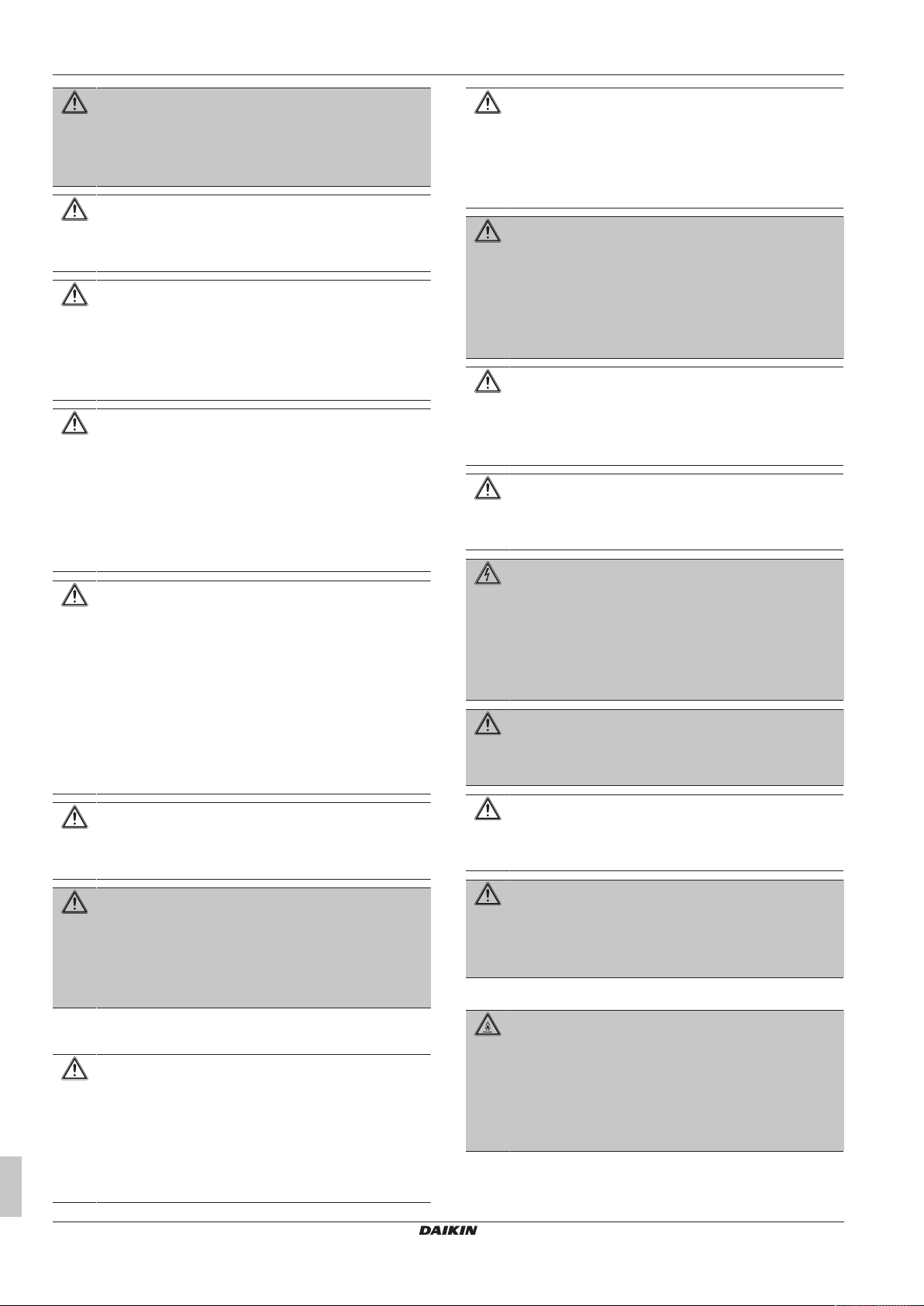
4.1 System layout
INFORMATION
The following illustration is an example and might NOT
match your system layout.
Turn off any combustible heating
devices, ventilate the room, and
contact the dealer from where you
purchased the unit.
Do not use the unit until a service
person confirms that the part from
which the refrigerant leaked has been
repaired.
Troubleshooting (see "8Troubleshooting"[411])
WARNING
Stop operation and shut off the
power if anything unusual occurs
(burning smells etc.).
Leaving the unit running under such
circumstances may cause breakage,
electric shock or fire. Contact your
dealer.
a Indoor unit
b Outdoor unit
c User interface
d Refrigerant piping + trasmission cable
e Drain pipe
FAA71+100BUV1B
Split system air conditioner
3P654518-1A – 2021.03
Installation and operation manual
7
5 User interface
a
c
d
b
e
f
g
h
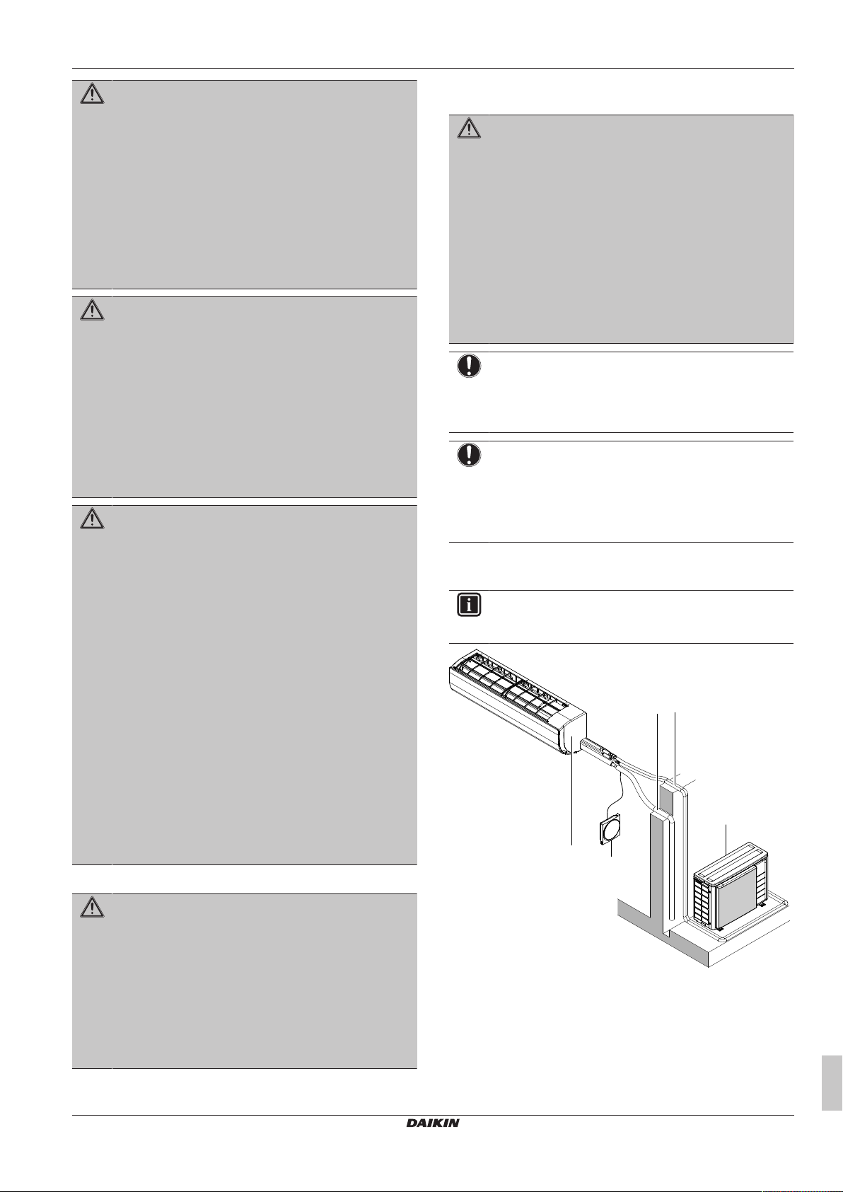
a Front panel
b Front grille
c Service cover
d Air filters
e Drain hose
f Refrigerant pipes
g Electrical wiring
h User interface
5 User interface
CAUTION
▪ NEVER touch the internal parts of the controller.
▪ Do NOT remove the front panel. Some parts inside are
dangerous to touch and appliance problems may
happen. For checking and adjusting the internal parts,
contact your dealer.
NOTICE
Do NOT wipe the controller operation panel with benzine,
thinner, chemical dust cloth, etc. The panel may get
discoloured or the coating peeled off. If it is heavily dirty,
soak a cloth in water-diluted neutral detergent, squeeze it
well and wipe the panel clean. Wipe it with another dry
cloth.
NOTICE
NEVER press the button of the user interface with a hard,
pointed object. The user interface may be damaged.
NOTICE
NEVER pull or twist the electric wire of the user interface. It
may cause the unit to malfunction.
This operation manual offers a non-exhaustive overview of the main
functions of the system.
For more information about the user interface, see the operation
manual of the installed user interface.
Outdoor units Cooling Heating
RZQSG71~140 Outdoor
–15~46°C DB –15~15.5°C WB
temperature
Indoor
14~28°C WB 10~27°C DB
temperature
Indoor humidity ≤80%
(a)
To avoid condensation and water dripping out of the unit. If the
temperature or the humidity is beyond these conditions, safety
devices may be put in action and the air conditioner may not
operate.
(a)
—
For combination with R32 outdoor unit, refer to the following table:
Outdoor units Cooling Heating
RZAG71~140 Outdoor
temperature
Indoor
temperature
RZASG71~140 Outdoor
temperature
Indoor
temperature
AZAS71+100 Outdoor
temperature
Indoor
temperature
RZA200+250 Outdoor
–20~52°C DB –20~24°C DB
–20~18°C WB
17~38°C DB
10~27°C DB
12~28°C WB
–15~46°C DB –15~21°C DB
–15~15.5°C WB
20~38°C DB
10~27°C DB
14~28°C WB
–5~46°C DB –15~21°C DB
–15~15.5°C WB
20~38°C DB
10~27°C DB
14~28°C WB
-20~46°C DB -20~15°C WB
temperature
Indoor
14~28°C WB 10~27°C DB
temperature
ARXM71 Outdoor
-10~46°C DB -15~18°C WB
temperature
Indoor
14~28°C WB 10~30°C DB
temperature
Indoor humidity ≤80%
(a)
To avoid condensation and water dripping out of the unit. If the
temperature or the humidity is beyond these conditions, safety
devices may be put in action and the air conditioner may not
operate.
(a)
—
DB: Dry bulb
WB: Wet bulb
6.2 About operation modes
6 Operation
6.1 Operation range
Use the system in the following temperature and humidity ranges for
safe and effective operation.
For combination with R410A outdoor unit, refer to the following table:
Outdoor units Cooling Heating
RZQ200 Outdoor
temperature
Indoor
temperature
RZQG71~140 Outdoor
temperature
Indoor
temperature
Installation and operation manual
8
–5~46°C DB –15~15°C WB
14~28°C WB 10~27°C DB
–15~50°C DB –20~15.5°C WB
12~28°C WB 10~27°C DB
INFORMATION
Depending on the installed system, some operation modes
will not be available.
▪ The air flow rate may adjust itself depending on the room
temperature or the fan may stop immediately. This is not a
malfunction.
▪ If the main power supply is turned off during operation, operation
will restart automatically after the power turns back on again.
▪ Setpoint. Target temperature for the Cooling, Heating, and Auto
operation modes.
▪ Setback. A function that keeps the room temperature in a specific
range when the system is turned off (by the user, the schedule
function, or the OFF timer).
6.2.1 Basic operation modes
The indoor unit can operate in various operation modes.
FAA71+100BUV1B
Split system air conditioner
3P654518-1A – 2021.03

6 Operation
a
b
aa
Icon Operation mode
Cooling. In this mode, cooling will be activated as
required by the setpoint, or by Setback operation.
Heating. In this mode, heating will be activated as
required by the setpoint, or by Setback operation.
Fan only. In this mode, air circulates without heating
or cooling.
Dry. In this mode, the air humidity will be lowered with
a minimal temperature decrease.
The temperature and fan speed are controlled
automatically and cannot be controlled by the
controller.
Dry operation will not function if the room temperature
is too low.
Auto. In Auto mode, the indoor unit automatically
switches between heating and cooling mode, as
required by the setpoint.
6.2.2 Special heating operation modes
Operation Description
Defrost To prevent a loss of heating
capacity due to frost
accumulation in the outdoor unit,
the system will automatically
switch to defrost operation.
During defrost operation, the
indoor unit fan will stop
operation, and the following icon
will appear on the home screen:
The system will resume normal
operation after approximately 6
to 8 minutes.
Hot start During hot start, the indoor unit
fan will stop operation, and the
following icon will appear on the
home screen:
Direction Screen
Fixed position. The indoor unit
blows air in 1 of 5 fixed positions.
Swing. The indoor unit alternates
between the 5 positions.
Note: Recommended position of the horizontal blades (flaps) varies
according to the operation mode.
a Cooling operation
b Heating operation
INFORMATION
For setting procedure of the vertical airflow direction, see
the reference guide or the manual of the used user
interface.
2 Horizontal airflow
▪ Horizontal airflow: by manually adjusting position of the vertical
blades (louvers).
To adjust the louvers (vertical blades)
1 Adjust horizontal blades using the user interface so you can
easily access the knobs on the vertical blades.
2 Hold knobs and move them down slightly.
3 Adjust left or right to the desired position while holding the
knobs.
6.2.3 Airflow direction
When. Adjust the airflow direction as desired.
What. The system directs the airflow differently, depending on the
user selection.
CAUTION
▪ ALWAYS use a user interface to adjust the angle of the
flap. When the flap is swinging and you move it forcibly
by hand, the mechanism will break.
▪ Be careful when adjusting the louvers. Inside the air
outlet, a fan is rotating at high speed.
1 Vertical airflow
The following vertical airflow directions can be set by the user
interface:
FAA71+100BUV1B
Split system air conditioner
3P654518-1A – 2021.03
6.3 To operate the system
a Knobs
INFORMATION
When the unit is installed in a corner of a room, the
direction of the louvers should be facing away from the
wall. Efficiency will drop if a wall blocks the air.
INFORMATION
For setting of the operation mode or other settings, see the
reference guide or operation manual of the user interface.
Installation and operation manual
9

7 Maintenance and service
a
7 Maintenance and service
7.1 Precautions for maintenance and service
NOTICE
Maintenance MUST be done by an authorized installer or
service agent.
We recommend performing maintenance at least once a
year. However, applicable legislation might require shorter
maintenance intervals.
CAUTION
Do NOT insert fingers, rods or other objects into the air
inlet or outlet. When the fan is rotating at high speed, it will
cause injury.
NOTICE
NEVER inspect or service the unit by yourself. Ask a
qualified service person to perform this work. However, as
end user, you may clean the air outlet, exterior, front panel
and air filter.
WARNING
NEVER replace a fuse with a fuse of a wrong ampere
ratings or other wires when a fuse blows out. Use of wire
or copper wire may cause the unit to break down or cause
a fire.
NOTICE
▪ Do NOT use gasoline, benzene, thinner polishing
powder or liquid insecticide. Possible consequence:
Discoloration and deformation.
▪ Do NOT use water or air of 50°C or higher. Possible
consequence: Discoloration and deformation.
▪ Do NOT scrub firmly when washing the blade with
water. Possible consequence: The surface sealing
peels off.
Clean with a soft cloth. If it is difficult to remove stains, use water or
neutral detergent.
7.2.2 To clean the front panel
WARNING
Do NOT let the indoor unit get wet. Possible
consequence: Electric shock or fire.
NOTICE
▪ Do NOT use gasoline, benzene, thinner polishing
powder or liquid insecticide. Possible consequence:
Discoloration and deformation.
▪ Do NOT use water or air of 50°C or higher. Possible
consequence: Discoloration and deformation.
You can remove the front panel to clean it.
1 Open the front panel. Hold the front panel by the panel tabs on
both sides and open until the panel stops.
CAUTION
After a long use, check the unit stand and fitting for
damage. If damaged, the unit may fall and result in injury.
CAUTION
Before accessing terminal devices, make sure to interrupt
all power supply.
DANGER: RISK OF ELECTROCUTION
To clean the air conditioner or air filter, be sure to stop
operation and turn all power supplies off. Otherwise, an
electric shock and injury may result.
WARNING
Be careful with ladders when working in high places.
Following symbols may occur on the indoor unit:
Symbol Explanation
Measure the voltage at the terminals of main circuit
capacitors or electrical components before servicing.
7.2 Cleaning the unit
CAUTION
Turn off the unit before cleaning the air outlet, exterior,
front panel and air filter.
a Panel tab
2 Remove the front panel by pushing hooks on either side of the
front panel towards the side of the unit and remove the panel.
3 Clean the front panel. Wipe it with a soft cloth soaked in water
by using only neutral detergent.
4 Wipe panel with a dry soft cloth and let it dry up in the shade.
5 Attach the front panel. Align the hooks of the front panel with
the slots and push them all the way in.
7.2.1 To clean the air outlet and exterior
WARNING
Do NOT let the indoor unit get wet. Possible
consequence: Electric shock or fire.
Installation and operation manual
10
FAA71+100BUV1B
Split system air conditioner
3P654518-1A – 2021.03

8 Troubleshooting
a
6 Close the front panel slowly.
7.2.3 To clean the air filter
NOTICE
Do NOT use water of 50°C or higher. Possible
consequence: Discoloration and deformation.
When to clean the air filter:
▪ Rule of thumb: Clean every 6months. If the air in the room is
extremely contaminated, increase the cleaning frequency.
▪ Depending on the settings, the user interface can display the
"Time to clean filter" notification. Clean the air filter when the
notification is displayed.
▪ If the dirt becomes impossible to clean, change the air filter
(=optional equipment).
How to clean the air filter:
1 Open the front panel. Hold the front panel by the panel tabs on
both sides and open until the panel stops.
a Panel tab
2 Remove the air filter. Push up the tab in the center of the air
filter slightly then pull the air filter out in a downward direction.
Global warming potential (GWP) value: 675
Refrigerant type: R410A
Global warming potential (GWP) value: 2087.5
NOTICE
Applicable legislation on fluorinated greenhouse gases
requires that the refrigerant charge of the unit is indicated
both in weight and CO2 equivalent.
Formula to calculate the quantity in CO2 equivalent
tonnes: GWP value of the refrigerant × total refrigerant
charge [in kg] / 1000
Please contact your installer for more information.
WARNING: MILDLY FLAMMABLE MATERIAL
The R32 refrigerant (if applicable) in this unit is mildly
flammable. Refer to the outdoor unit specifications for the
type of refrigerant to be used.
WARNING
The appliance using R32 refrigerant shall be stored so as
to prevent mechanical damage and in a well-ventilated
room without continuously operating ignition sources (e.g.
open flames, an operating gas appliance, or an operating
electric heater). The room size shall be as specified in the
General safety precaution.
WARNING
▪ Do NOT pierce or burn refrigerant cycle parts.
▪ Do NOT use cleaning materials or means to accelerate
the defrosting process other than those recommended
by the manufacturer.
▪ Be aware that the refrigerant inside the system is
odourless.
3 Clean the air filter. Use a vacuum cleaner or wash with water.
If the air filter is very dirty, use a soft brush and neutral
detergent.
4 Dry the air filter in the shadow.
5 Reattach the air filter. Replace the air filter as it was.
6 Close the front panel. Hold the front panel by the panel tabs
on both sides and close it slowly.
7 Turn ON the power.
8 To remove warning screens, see the reference guide of the
user interface.
7.3 About the refrigerant
This product contains fluorinated greenhouse gases. Do NOT vent
gases into the atmosphere.
Refrigerant type: R32
WARNING
R410A is a non-combustible refrigerant, and R32 is a
mildly flammable refrigerant; they normally don’t leak. If the
refrigerant leaks in the room and comes into contact with
fire from a burner, a heater, or a cooker, this may result in
a fire (in case of R32), or the formation of a harmful gas.
Turn off any combustible heating devices, ventilate the
room, and contact the dealer from where you purchased
the unit.
Do not use the unit until a service person confirms that the
part from which the refrigerant leaked has been repaired.
8 Troubleshooting
If one of the following malfunctions occur, take the measures shown
below and contact your dealer.
WARNING
Stop operation and shut off the power if anything
unusual occurs (burning smells etc.).
Leaving the unit running under such circumstances may
cause breakage, electric shock or fire. Contact your dealer.
The system MUST be repaired by a qualified service person.
Malfunction Measure
If a safety device such as a fuse, a
circuit breaker or a residual current
device frequently actuates or the ON/
OFF switch does NOT function properly.
If water leaks from the unit. Stop operation.
Turn OFF all main power
supply switches to the
unit.
FAA71+100BUV1B
Split system air conditioner
3P654518-1A – 2021.03
Installation and operation manual
11

9 Relocation
1×1× 1× 4× 1× 3× 1×
cba d e f g
Malfunction Measure
The operation switch does NOT function
properly.
If the user interface displays .
If the system does NOT operate properly except for the above
mentioned cases and none of the above mentioned malfunctions is
evident, investigate the system in accordance with the following
procedures.
INFORMATION
Refer to the reference guide located on http://
www.daikineurope.com/support-and-manuals/productinformation/ for more troubleshooting tips.
Turn OFF the power
supply.
Notify your installer and
report the error code. To
display an error code see
the reference guide of the
user interface.
For the installer
If after checking all above items, it is impossible to fix the problem
yourself, contact your installer and state the symptoms, the complete
model name of the unit (with manufacturing number if possible) and
the installation date (possibly listed on the warranty card).
9 Relocation
Contact your dealer for removing and reinstalling the total unit.
Moving units requires technical expertise.
10 Disposal
NOTICE
Do NOT try to dismantle the system yourself: dismantling
of the system, treatment of the refrigerant, oil and other
parts MUST comply with applicable legislation. Units
MUST be treated at a specialised treatment facility for
reuse, recycling and recovery.
11 About the box
11.1 Indoor unit
WARNING: MILDLY FLAMMABLE MATERIAL
The R32 refrigerant (if applicable) in this unit is mildly
flammable. Refer to the outdoor unit specifications for the
type of refrigerant to be used.
▪ At delivery, the unit MUST be checked for damage. Any damage
MUST be reported immediately to the claims agent of the carrier.
▪ Bring the packed unit as close as possible to its final installation
position to prevent damage during transport.
▪ Unpack the indoor unit completely according to the instructions
mentioned on the unpacking instructions sheet.
11.1.1 To remove the accessories from the indoor unit
1 Remove:
▪ the accessory bag located at the bottom of the package,
▪ the mounting plate attached to the back of the indoor unit.
12 Unit installation
INFORMATION
If you are not sure how to open or close parts of the unit
(front panel, electrical wiring box, front grille…) refer to the
installer reference guide of the unit for opening and closing
procedures.
WARNING
Installation shall be done by an installer, the choice of
materials and installation shall comply with the applicable
legislation. In Europe, EN378 is the applicable standard.
12.1 Preparing the installation site
Avoid installation in an environment with a lot of organic solvents
such as ink and siloxane.
WARNING
The appliance using R32 refrigerant shall be stored so as
to prevent mechanical damage and in a well-ventilated
room without continuously operating ignition sources (e.g.
open flames, an operating gas appliance, or an operating
electric heater). The room size shall be as specified in the
General safety precaution.
12.1.1 Installation site requirements of the indoor unit
a Installation and operation manual
b General safety precautions
c Fixing screws M4×25L for the mounting plate (9×),
securing screws M4×12L (2× for 71 class, 3× for 100
class)
d Tie wraps (1 large, 3 small)
e Insulation tape
f Screws cover (for 100 class only)
g Mounting plate
Installation and operation manual
12
INFORMATION
The sound pressure level is less than 70dBA.
CAUTION
Appliance not accessible to the general public, install it in a
secured area, protected from easy access.
This unit, both indoor and outdoor, is suitable for
installation in a commercial and light industrial
environment.
FAA71+100BUV1B
Split system air conditioner
3P654518-1A – 2021.03

▪ Wall insulation. When conditions in the wall exceed 30°C and a
≤120
≥90
≥30
a
b ≥1800
≥50 ≥50
≥90
(mm)
A
b
a
b
1
1
c
2
c
2
c
2
3
B
c
2
2
2
2
3
a
b
1
c c
c
a
b
c
d
e
f
relative humidity of 80%, or when fresh air is inducted into the
wall, then additional insulation is required (minimum 10 mm
thickness, polyethylene foam).
▪ Wall strength. Check whether the wall is strong enough to
support the weight of the unit. If there is a risk, reinforce the wall
before installing the unit.
▪ Air flow. Make sure nothing blocks the air flow.
▪ Drainage. Make sure condensation water can be evacuated
properly.
▪ Spacing. Mind the following requirements:
12 Unit installation
A Class 71
B Class 100
a Mounting plate
b Screw
c Knob
2 Choose position for piping (for bottom or side piping see
"12.2.3To remove the pipe port cover"[414]):
a Obstruction
b Minimum distance to the floor
NOTICE
NEVER mount the indoor unit directly on the wall. Use the
attached mounting plate for installation.
12.2 Mounting the indoor unit
12.2.1 To install the mounting plate
1 Remove the mounting plate from the unit.
▪ Remove 2 screws from class 71 or 1 screw from class 100.
▪ Push the knobs in the direction of the arrow.
▪ Remove the mounting plate.
a Right piping
b Bottom-right piping
c Back-right piping
d Bottom-left piping
e Back-left piping
f Left piping
3 Attach the mounting plate on the wall and install it temporarily.
4 Level the mounting plate (use tabs on the mounting plate).
5 Mark the centers of the drilling points on the wall using a tape
measure. Position the end of tape measure at symbol " ".
6 Finish the installation by securing the mounting plate on the
wall:
▪ When using M4×25L screws (accessory), install evenly at least 4
screws on each side.
▪ When using bolts (Example: for concrete wall): use M8~M10
bolts (field supply) one for each side.
INFORMATION
The removed pipe port cover can be kept in the mounting
plate pocket.
FAA71+100BUV1B
Split system air conditioner
3P654518-1A – 2021.03
Installation and operation manual
13

12 Unit installation
A
(mm)
60 85
480 411
1050
104 98
344
389
44
44
103
52
101
290
d
e
ca a ac
ia
d
e
b
a a a a
f
f
gh
B
(mm)
1200
543 503
16465
186 89
393
459
45
45
80
36
194
340
a a a
a
a a aa
i
b c c
d
e
d
e
f
f
gh
Ø80
a
b
c
A Pattern for installation with mounting plate for class 71
B Pattern for installation with mounting plate for class 100
a Recommended fixing spots
b Pocket for the pipe port cover
c Tabs for placing a spirit level
d Through-the-wall hole Ø80mm
e Drain hose position
f Position for the tape measure at symbol " "
g Gas pipe end
h Liquid pipe end
i Temporary fixing hole
12.2.2 To drill a wall hole
CAUTION
For walls containing a metal frame or a metal board, use a
wall embedded pipe and wall cover in the feed-through
hole to prevent possible heat, electrical shock, or fire.
NOTICE
Be sure to seal the gaps around the pipes with sealing
material (field supply), in order to prevent water leakage.
1 Drill a 80 mm large feed-through hole in the wall with a
downward slope towards the outside.
2 Insert a wall embedded pipe into the hole.
3 Insert a wall cover into the wall pipe.
Installation and operation manual
14
a Wall embedded pipe (field supply)
b Putty (field supply)
c Wall hole cover (field supply)
4 After completing wiring, refrigerant piping and drain piping, do
NOT forget to seal the gap with putty.
12.2.3 To remove the pipe port cover
INFORMATION
To connect the piping on right-side, right-bottom, left-side
or left-bottom, the pipe port cover MUST be removed.
Split system air conditioner
3P654518-1A – 2021.03
FAA71+100BUV1B

a
b
a Cut off for side piping
a
c
db e
c
e f
bda
A
A
c g
b Cut off for bottom piping
1 Remove the front grille.
2 Cut off the pipe port cover from inside the front grille using a
coping saw.
3 Remove any burrs along the cut section using a half round
needle file.
12 Unit installation
2 Shape the refrigerant pipes along the pipe path marking on the
mounting plate.
3 Fix the electrical wiring and the refrigerant pipes together using
vinyl tape (field supply).
a Drain hose
b Wall hole
c Refrigerant piping
d Electrical wiring
e Vinyl tape (field supply)
f Power supply wiring
g Transmission wiring and user interface wiring
NOTICE
▪ Do NOT bend refrigerant pipes.
▪ Do NOT push the refrigerant pipes onto the bottom
frame or the front grille.
NOTICE
Do NOT use nippers to remove the pipe port cover, as this
would damage the front grille.
12.2.4 To hook the unit on the mounting plate
1 Remove the front panel.
2 Set the indoor unit on the mounting plate hooks. Use the " "
marks as a guide.
3 Place piece of packing material for support.
a Front grille
b Refrigerant piping
c Tab 2×
d Mounting plate (accessory)
e Piece of packing material
12.2.5 To pass the pipes through the wall hole
1 Connect the drain piping "12.2.6 To provide drainage" [4 15],
the refrigerant piping "13 Piping installation" [4 16] and the
electrical wiring "14Electrical installation"[417].
4 Pass the drain hose and refrigerant pipes through the wall hole.
5 When the complete installation is finished (drain piping
"12.2.6 To provide drainage" [4 15], the refrigerant piping
"13 Piping installation" [4 16] and the electrical wiring
"14 Electrical installation" [4 17]), fix the indoor unit on the
mounting plate "15.1 To fix the unit on the mounting
plate"[419].
12.2.6 To provide drainage
INFORMATION
Make sure to check and follow the General guidelines for
draining in the installer reference guide of the indoor unit.
To connect the piping on right side, right-back, or right-bottom
INFORMATION
The factory default is right-side piping. For left-side piping,
remove the piping from the right side and install it on the
left side.
1 Attach the drain hose with adhesive vinyl tape to the bottom of
the refrigerant pipes.
2 Wrap the drain hose and the refrigerant pipes together using
insulation tape.
FAA71+100BUV1B
Split system air conditioner
3P654518-1A – 2021.03
Installation and operation manual
15

13 Piping installation
A
B
C
a
b
A
B
C
b
a
a
b
t
Ø
ØiØ
i
t
ØpØ
p
A Right-side piping
B Right-bottom piping
C Right-back piping
a Remove the pipe port cover here for right side piping
b Remove the pipe port cover here for right-bottom piping
To connect the piping on left side, left-back, or leftbottom
INFORMATION
The factory default is right-side piping. For left-side piping,
remove the piping from the right side and install it on the
left side.
1 Remove the insulation fixing screw on the right side and
remove the drain hose.
2 Remove the drain plug on the left side and attach it to the right
side.
NOTICE
Do NOT apply lubricating oil (refrigerant oil) to the drain
plug when inserting it. The drain plug may deteriorate and
cause drain leakage from the plug.
3 Insert the drain hose on the left side and do not forget to tighten
it with the fixing screw; otherwise water leakage may occur.
4 Attach the drain hose to the refrigerant piping bottom side using
adhesive vinyl tape.
13 Piping installation
13.1 Preparing refrigerant piping
13.1.1 Refrigerant piping requirements
CAUTION
Piping MUST be installed according to instructions given in
"13Piping installation"[416]. Only mechanical joints (e.g.
braze+flare connections) that are compliant with the latest
version of ISO14903 can be used.
NOTICE
The piping and other pressure-containing parts shall be
suitable for refrigerant. Use phosphoric acid deoxidised
seamless copper for refrigerant.
▪ Foreign materials inside pipes (including oils for fabrication) must
be ≤30mg/10m.
Refrigerant piping diameter
For piping connections of the indoor unit use the following piping
diameters:
Pipe outer diameter (mm)
Liquid pipe Gas pipe
Ø9.5 Ø15.9
Refrigerant piping material
▪ Piping material: Phosphoric acid deoxidised seamless copper.
▪ Flare connections: Only use annealed material.
▪ Piping temper grade and thickness:
Outer diameter
(Ø)
9.5mm (3/8") Annealed (O) ≥0.8mm
15.9mm (5/8") Annealed (O)
Temper grade Thickness (t)
(a)
A Left-side piping
B Left-back piping
C Left-bottom piping
a Remove the pipe port cover here for left-side piping
b Remove the pipe port cover here for left-bottom piping
To check for water leaks
1 Remove the air filters (see "7.2.3To clean the air filter"[411]).
2 Gradually pour approximately 1l of water in the drain pan, and
check for water leaks.
a Drain pan
b Plastic container
3 Reattach the air filters (see "7.2.3To clean the air filter"[411]).
(a)
Depending on the applicable legislation and the maximum
working pressure of the unit (see "PS High" on the unit name
plate), larger piping thickness might be required.
13.1.2 Refrigerant piping insulation
▪ Use polyethylene foam as insulation material:
▪ with a heat transfer rate between 0.041 and 0.052W/mK (0.035
and 0.045kcal/mh°C)
▪ with a heat resistance of at least 120°C
▪ Insulation thickness
Pipe outer diameter
(Øp)
9.5mm (3/8") 12~15mm ≥13mm
15.9mm (5/8") 17~20mm ≥13mm
If the temperature is higher than 30°C and the humidity is higher
than RH 80%, the thickness of the insulation materials should be at
least 20 mm to prevent condensation on the surface of the
insulation.
Insulation inner
diameter (Øi)
Insulation thickness
(t)
Installation and operation manual
16
FAA71+100BUV1B
Split system air conditioner
3P654518-1A – 2021.03

14 Electrical installation
d
f
b
e
g
a c
h
db
i
13.2 Connecting the refrigerant piping
DANGER: RISK OF BURNING/SCALDING
13.2.1 To connect the refrigerant piping to the indoor unit
CAUTION
Install the refrigerant piping or components in a position
where they are unlikely to be exposed to any substance
which may corrode components containing refrigerant,
unless the components are constructed of materials that
are inherently resistant to corrosion or are suitably
protected against corrosion.
WARNING: MILDLY FLAMMABLE MATERIAL
The R32 refrigerant (if applicable) in this unit is mildly
flammable. Refer to the outdoor unit specifications for the
type of refrigerant to be used.
▪ Pipe length. Keep refrigerant piping as short as possible.
1 Flare connections. Connect refrigerant piping to the unit using
flare connections.
2 Insulation. Insulate the refrigerant piping, the insulating tape
should be wrapped from the L-shaped bend all the way to the
end inside the unit as follows:
WARNING
Use an all-pole disconnection type breaker with at least
3 mm between the contact point gaps that provide full
disconnection under overvoltage category III.
WARNING
If the supply cord is damaged, it MUST be replaced by the
manufacturer, its service agent or similarly qualified
persons in order to avoid a hazard.
14.1 Specifications of standard wiring components
Component Specification
Interconnection cable
(indoor↔outdoor)
User interface cable Vinyl cords with 0.75 to
(a)
In case the conduit pipes are not used, use H07RN-F (60245 IEC
66).
4-core cable
1.5mm2~2.5mm2 and
applicable for 220~240V
H05RN-F (60245 IEC 57)
1.25mm² sheath or cables
(2‑core wires)
H03VV-F (60227 IEC 52)
Maximum 500m
(a)
a Field piping
b Indoor unit piping insulation tubing
c Indoor unit piping
d Insulating tubing tape
e Insulating tape (accessory)
f Large tie wrap (accessory)
g Beginning of wrapping
h L-shaped bend
i Insulation tubing seam (make sure there are no gaps in
the insulation tubing seam)
NOTICE
Make sure to insulate all refrigerant piping. Any exposed
piping might cause condensation.
14 Electrical installation
DANGER: RISK OF ELECTROCUTION
WARNING
▪ All wiring MUST be performed by an authorised
electrician and MUST comply with the applicable
legislation.
▪ Make electrical connections to the fixed wiring.
▪ All components procured on-site and all electrical
construction MUST comply with the applicable
legislation.
WARNING
ALWAYS use multicore cable for power supply cables.
14.2 To connect the electrical wiring to the indoor unit
NOTICE
▪ Follow the wiring diagram (delivered with the unit,
located at the inside of the service cover).
▪ For instructions on how to connect the optional
equipment, see the installation manual delivered with
the optional equipment.
▪ Make sure the electrical wiring does NOT obstruct
proper reattachment of the service cover.
It is important to keep the power supply and the transmission wiring
separated from each other. In order to avoid any electrical
interference the distance between both wirings should ALWAYS be
at least 50mm.
NOTICE
Be sure to keep the power line and transmission line apart
from each other. Transmission wiring and power supply
wiring may cross, but may NOT run parallel.
1 Remove the service cover and shield plate.
2 User interface cable: Connect the cable to the terminal block
(symbols P1, P2).
3 Interconnection cable (indoor↔outdoor): Route the cable
through the frame, connect the cable to the terminal block
(make sure the numbers match with the numbers on the
outdoor unit, and connect the earth wire), and fix the cable with
a cable tie.
4 Seal all gaps with a sealing material (field supply) to prevent
small animals from entering the system.
5 Reattach the shield plate and the service cover.
FAA71+100BUV1B
Split system air conditioner
3P654518-1A – 2021.03
Installation and operation manual
17

14 Electrical installation
1
3
2
P
1
REMOTE
CNTRL
TRANSMISSION
WIRING
FORCED
OFF
T
2
P2F1F2T
1
1
3
2
e
70~90
10~20
R-Ctrl D III-Net
F1 F2 T1 T2P1 P2
70~90
7
b
c
d
a
a
P1 P2
21 3
P1 P2
21 3
e
b
c
d
a
21 3
P1 P2
P1 P2
P1 P2
21 3
1 2 3
e
c
d1 d2
b
a
P1 P2
1 2 3
21 3 1 2 3
P1 P2 P1 P2 P1 P2
21 3 21 3 1 2 3
e
c c c
d1 d2 d2
b b b
a a a
b(1)
b(2)
b(16)
d
a(1)
c
a(2)
a(16)
a Interconnection wiring terminal
b User interface wiring terminal
c Interconnection wiring cable
d User interface terminal wiring cable
e Small tie wrap (accessory)
Electrical wiring route:
a Power supply
b Residual current device
c Outdoor unit
d Indoor unit
e User interface
Group control: 1 remote controller controls up to 4 indoor units
(all indoor units operate according to the user interface)
a Electrical wiring
Complete system wiring example
For the wiring of outdoor units, refer to the installation manual
attached to the outdoor units.
Pair type: 1 remote controller controls 1 indoor unit (standard)
a Power supply
b Residual current device
c Outdoor unit
d Indoor unit
e User interface
Simultaneous operation system: 1 user interface controls 2
indoor units (2 indoor units operates equally)
Installation and operation manual
18
a Power supply
b Residual current device
c Outdoor unit
d1 Indoor unit (master)
d2 Indoor unit (slave)
e User interface
▪ When using a pair type system as a master system for
simultaneous multiple unit operation, you may carry out
simultaneous start/stop (group) control up to 16 units with 1
remote controller. (All indoor units operate according to the user
interface)
▪ The thermistor reading of room temperature is effective only for
the indoor unit connected to the user interface.
a Outdoor unit (number)
b Indoor unit (number)
c Slave indoor unit
d User interface
2 remote controllers control: 2 remote controllers control 1
indoor unit.
FAA71+100BUV1B
Split system air conditioner
3P654518-1A – 2021.03

21 3
P1 P2
21 3
e(1) e(2)
b
c
d
a
P2 P1 P2P1
a Power supply
P1 P2 F1 F2
b
a
c
a
b
e
c
d
b Residual current device
c Outdoor unit
d Indoor unit
e User interface
1 Remove the service cover.
2 Lay crossover between the terminals (P1, P2) inside the control
box for the remote controller (there is no polarity). For
simultaneous operation system, be sure to connect the user
interface to the master unit.
a Terminal block (X1M) (Master unit)
b User interface (MAIN)
c User interface (SUB)
3 When using 2 user interfaces, one must be set to “MAIN” and
the other to “SUB”. For setting refer to the installation manual of
the connected user interface.
15 Finishing the indoor unit
installation
15 Finishing the indoor unit installation
a Mounting plate (accessory)
b Refrigerant piping
c Insulation tape
d Bottom frame
e Screw M4×12L ( accessory) 2 for class 71, 3 for class
100
5 Re-install the front grille and front panel.
16 Commissioning
NOTICE
General commissioning checklist. Next to the
commissioning instructions in this chapter, a general
commissioning checklist is also available on the Daikin
Business Portal (authentication required).
The general commissioning checklist is complementary to
the instructions in this chapter and can be used as a
guideline and reporting template during the commissioning
and hand-over to the user.
NOTICE
ALWAYS operate the unit with thermistors and/or pressure
sensors/switches. If NOT, burning of the compressor might
be the result.
16.1 Checklist before commissioning
After the installation of the unit, first check the items listed below.
Once all checks are fulfilled, the unit must be closed. Power-up the
unit after it is closed.
You read the complete installation and operation
instructions, as described in the installer and user
reference guide.
The indoor unit is properly mounted.
The outdoor unit is properly mounted.
Make sure drain piping is properly installed, insulated
and drainage flows smoothly. Check for water leaks.
Possible consequence: Condensate water might drip.
The refrigerant pipes (gas and liquid) are installed
correctly and thermally insulated.
There are NO refrigerant leaks.
15.1 To fix the unit on the mounting plate
1 Remove the piece of packing material.
2 Press the bottom frame of the unit with both hands to set it on
the bottom hooks of the mounting plate. Make sure that the
wires do NOT get squeezed or caught anywhere.
3 Press the bottom edge of the indoor unit with both hands until it
is firmly caught by the mounting plate hooks.
4 Secure the indoor unit to the mounting plate using indoor unit
fixing screws M4×12L (2 for class 71, 3 for class 100)
(accessory).
FAA71+100BUV1B
Split system air conditioner
3P654518-1A – 2021.03
There are NO missing phases or reversed phases.
The system is properly earthed and the earth terminals
are tightened.
The fuses or locally installed protection devices are
installed according to this document, and have NOT been
bypassed.
The power supply voltage matches the voltage on the
identification label of the unit.
There are NO loose connections or damaged electrical
components in the switchbox.
There are NO damaged components or squeezed
pipes on the inside of the indoor and outdoor units.
The stop valves (gas and liquid) on the outdoor unit are
fully open.
Installation and operation manual
19

17 Configuration
16.2 To perform a test run
INFORMATION
For the test run procedure, see the reference guide or the
service manual of the used user interface.
NOTICE
Do NOT interrupt the test run.
17 Configuration
17.1 Field setting
Make the following field settings so that they correspond with the
actual installation setup and with the needs of the user:
▪ Airflow rate increase mode
▪ Airflow rate when thermostat control is OFF
▪ Time to clean air filter
▪ Indoor unit number of simultaneous operation system
▪ Simultaneous operation system individual setting
▪ Computerised control (forced OFF and ON/OFF operation)
INFORMATION
▪ The connection of optional accessories to the indoor
unit might cause changes to some field settings. For
more information, see the installation manual of the
optional accessory.
▪ Following setting are only applicable when using the
BRC1H52* user interface. When using any other user
interface, see the installation manual or service manual
of the user interface.
Setting: Airflow rate increase mode
This setting must correspond with the needs of the user. It is
possible to raise set airflow (HIGH, MEDIUM and LOW) from the
field. Change the value number (—) as shown in the table below.
If you want airflow… Then
M SW —
Standard 13 (23) 0 01
A little increased 02
Increased 03
Setting: Airflow rate when thermostat control is OFF
This setting must correspond with the needs of the user. It
determines the fan speed of the indoor unit during thermostat OFF
condition.
1 If you have set the fan to operate, set the airflow rate speed:
(1)
If you want… Then
(1)
M SW —
Fan operation
during thermostat
OFF (cooling/
Normal 11 (21) 2 01
Stop 02
heating operation)
During thermostat
OFF at cooling
operation
During thermostat
OFF at heating
operation
(2)
LL
Setup volume
(2)
12 (22) 6 01
02
OFF 03
Monitoring 1
Monitoring 3
(2)
LL
Setup volume
(2)
(2)
04
05
12 (22) 3 01
(2)
02
OFF 03
Monitoring 1
Monitoring 2
(2)
(2)
04
05
Setting: Time to clean air filter
This setting must correspond with the air contamination in the room.
It determines the interval at which "Time to clean filter" notification
is displayed on the user interface.
If you want an interval of…
(air contamination)
M SW —
Then
(1)
±200h (light) 10 (20) 0 01
±100h (heavy) 02
Setting: Indoor unit number of simultaneous operation system
For simultaneous operation system mode made following field
setting:
If the system mode is… Then
(1)
M SW —
Pair (1 unit) 11 (21) 0 01
Simultaneous (2 units) 02
Simultaneous (3 units) 03
When using in simultaneous operation system mode, refer to
“simultaneous operation system individual setting” section to set
master and slave units separately.
When using wireless remote controllers, wireless remote
controller address setting is necessary. Refer to the installation
manual attached to the wireless remote controller for setting
instructions.
Setting: Simultaneous operation system individual setting
Perform the following procedure when setting the master and slave
unit separately.
1 Change setting:
If you want… Then
(1)
M SW —
Unified setting 11 (21) 1 01
Individual setting 02
(1)
Field settings are defined as follows:
• M: Mode number – First number: for group of units – Number between brackets: for individual unit
• SW: Setting number
• —: Value number
• : Default
(2)
Fan speed:
• LL: Low fan speed (set during thermostat OFF)
• L: Low fan speed (set by the user interface)
• Setup volume: The fan speed corresponds to the speed the user has set using the fan speed button on the user interface.
• Monitoring 1, 2, 3: The fan is OFF, but runs for a short time every 6minutes to detect the room temperature by LL (Monitoring 1), L
(Monitoring 2) or Setup volume (Monitoring 3).
Installation and operation manual
20
2 Perform field setting for the master unit.
FAA71+100BUV1B
Split system air conditioner
3P654518-1A – 2021.03

18 Technical data
F2 T1 T2
FORCED
OFF
a
,
A
INDOOR
OUTDOOR
3 Turn off main power supply.
4 Detach user interface from the master unit and connect it to the
slave unit.
Turn on the main power supply switch and set individual setting.
5 Perform field setting for slave unit.
6 Turn off the main power supply.
7 If there is more than one slave unit, repeat setting for each
8 Detach user interface from the slave unit, and reattach to the
master unit.
INFORMATION
▪ You do not need to rewire the user interface from the
master unit if the optional remote controller for slave
unit is used. However, remove the wires attached to the
user interface terminal board of the master unit.
▪ After the slave unit setting, remove the user interface
wiring, and rewire the user interface from the master
unit.
▪ The unit does not operate properly when two or more
user interfaces are attached to the unit in the
simultaneous operation system mode.
Setting: Computerised control (forced OFF and ON/OFF
operation)
Wire specifications and how to perform wiring
Connect input from outside to terminals T1 and T2 of the terminal
block for user interface (there is no polarity).
18 Technical data
▪ A subset of the latest technical data is available on the regional
Daikin website (publicly accessible).
▪ The full set of latest technical data is available on the Daikin
Business Portal (authentication required).
18.1 Wiring diagram
18.1.1 Unified wiring diagram legend
For applied parts and numbering, refer to the wiring diagram on the
unit. Part numbering is by Arabic numbers in ascending order for
each part and is represented in the overview below by "*" in the part
code.
Symbol Meaning Symbol Meaning
Circuit breaker Protective earth
Connection Protective earth (screw)
Connector
Earth Relay connector
Field wiring Short-circuit connector
Fuse Terminal
Indoor unit Terminal strip
Rectifier
a Input A
Wire specification
Wire specification Sheathed vinyl cord or cable (2 wire)
Gauge 0.75~1.25mm
2
External terminal Contact that can ensure the minimum
applicable load of 15VDC, 10mA.
Actuation
Forced OFF ON/OFF operation
Input „ON“ stops operation
(impossible by user inteface)
Input OFF enables control by
user interface
a) Input OFF → ON
Result: turns the unit ON
a) Input ON → OFF
Result: Turns the unit OFF
How to select FORCED OFF and ON/OFF OPERATION
1 Turn on the power and then use the user interface to select
operation.
2 Change setting:
If you want… Then
(1)
M SW —
Forced OFF 12 (22) 1 01
ON/OFF operation 02
Outdoor unit Wire clamp
Residual current
device
Symbol Colour Symbol Colour
BLK Black ORG Orange
BLU Blue PNK Pink
BRN Brown PRP, PPL Purple
GRN Green RED Red
GRY Grey WHT White
YLW Yellow
Symbol Meaning
A*P Printed circuit board
BS* Pushbutton ON/OFF, operation
switch
BZ, H*O Buzzer
C* Capacitor
AC*, CN*, E*, HA*, HE*, HL*,
Connection, connector
HN*, HR*, MR*_A, MR*_B, S*, U,
V, W, X*A, K*R_*, NE
D*, V*D Diode
DB* Diode bridge
DS* DIP switch
E*H Heater
FU*, F*U, (for characteristics,
Fuse
refer to PCB inside your unit)
FAA71+100BUV1B
Split system air conditioner
3P654518-1A – 2021.03
(1)
Field settings are defined as follows:
• M: Mode number – First number: for group of units – Number between brackets: for individual unit
• SW: Setting number
• —: Value number
• : Default
Installation and operation manual
21

18 Technical data
Symbol Meaning
FG* Connector (frame ground)
H* Harness
H*P, LED*, V*L Pilot lamp, light emitting diode
HAP Light emitting diode (service
monitor green)
HIGH VOLTAGE High voltage
IES Intelligent eye sensor
IPM* Intelligent power module
K*R, KCR, KFR, KHuR, K*M Magnetic relay
L Live
L* Coil
L*R Reactor
M* Stepper motor
M*C Compressor motor
M*F Fan motor
M*P Drain pump motor
M*S Swing motor
MR*, MRCW*, MRM*, MRN* Magnetic relay
N Neutral
n=*, N=* Number of passes through ferrite
core
PAM Pulse-amplitude modulation
PCB* Printed circuit board
PM* Power module
PS Switching power supply
PTC* PTC thermistor
Q* Insulated gate bipolar transistor
(IGBT)
Q*C Circuit breaker
Q*DI, KLM Earth leak circuit breaker
Q*L Overload protector
Q*M Thermo switch
Q*R Residual current device
R* Resistor
R*T Thermistor
RC Receiver
S*C Limit switch
S*L Float switch
S*NG Refrigerant leak detector
S*NPH Pressure sensor (high)
S*NPL Pressure sensor (low)
S*PH, HPS* Pressure switch (high)
S*PL Pressure switch (low)
S*T Thermostat
S*RH Humidity sensor
S*W, SW* Operation switch
SA*, F1S Surge arrester
SR*, WLU Signal receiver
SS* Selector switch
SHEET METAL Terminal strip fixed plate
T*R Transformer
TC, TRC Transmitter
V*, R*V Varistor
Symbol Meaning
V*R Diode bridge, Insulated-gate
bipolar transistor (IGBT) power
module
WRC Wireless remote controller
X* Terminal
X*M Terminal strip (block)
Y*E Electronic expansion valve coil
Y*R, Y*S Reversing solenoid valve coil
Z*C Ferrite core
ZF, Z*F Noise filter
Installation and operation manual
22
FAA71+100BUV1B
Split system air conditioner
3P654518-1A – 2021.03


Verantwortung für Energie und Umwelt
Copyright 2021 Daikin
3P654518-1A 2021.03
 Loading...