

Installer and user reference guide
Split system air conditioner
FAA71BUV1B
FAA100BUV1B

Table of contents
Table of contents
1 About the documentation 5
1.1 About this document ...................................................................................................................................................... 5
1.2 Meaning of warnings and symbols................................................................................................................................. 6
2 General safety precautions 8
2.1 For the installer............................................................................................................................................................... 8
2.1.1 General ........................................................................................................................................................... 8
2.1.2 Installation site ............................................................................................................................................... 9
2.1.3 Refrigerant — in case of R410A or R32.......................................................................................................... 12
2.1.4 Electrical ......................................................................................................................................................... 13
3 Specific installer safety instructions 16
For the user 18
4 User safety instructions 19
4.1 General............................................................................................................................................................................ 19
4.2 Instructions for safe operation ....................................................................................................................................... 20
5 About the system 25
5.1 System layout.................................................................................................................................................................. 25
6 User interface 27
7 Before operation 28
8 Operation 29
8.1 Operation range.............................................................................................................................................................. 29
8.2 About operation modes.................................................................................................................................................. 30
8.2.1 Basic operation modes ................................................................................................................................... 30
8.2.2 Special heating operation modes................................................................................................................... 31
8.2.3 Airflow direction ............................................................................................................................................. 31
8.3 To operate the system.................................................................................................................................................... 32
9 Energy saving and optimum operation 33
10 Maintenance and service 34
10.1 Precautions for maintenance and service ...................................................................................................................... 34
10.2 Cleaning the unit ............................................................................................................................................................. 35
10.2.1 To clean the air outlet and exterior ............................................................................................................... 35
10.2.2 To clean the front panel................................................................................................................................. 35
10.2.3 To clean the air filter ...................................................................................................................................... 36
10.3 Maintenance before a long stop period......................................................................................................................... 37
10.4 Maintenance after a long stop period............................................................................................................................ 37
10.5 About the refrigerant...................................................................................................................................................... 38
11 Troubleshooting 39
11.1 Symptoms that are NOT system malfunctions............................................................................................................... 40
11.1.1 Symptom: The system does not operate....................................................................................................... 40
11.1.2 Symptom: The fan speed does not correspond to the setting...................................................................... 40
11.1.3 Symptom: The fan direction does not correspond to the setting................................................................. 40
11.1.4 Symptom: White mist comes out of a unit (Indoor unit) .............................................................................. 41
11.1.5 Symptom: White mist comes out of a unit (Indoor unit, outdoor unit)........................................................ 41
11.1.6 Symptom: The user interface reads "U4" or "U5" and stops, but then restarts after a few minutes.......... 41
11.1.7 Symptom: Noise of air conditioners (Indoor unit)......................................................................................... 41
11.1.8 Symptom: Noise of air conditioners (Indoor unit, outdoor unit).................................................................. 41
11.1.9 Symptom: Dust comes out of the unit........................................................................................................... 41
11.1.10 Symptom: The units can give off odours ....................................................................................................... 41
Installer and user reference guide
2
12 Relocation 42
13 Disposal 43
For the installer 44
14 About the box 45
FAA71+100BUV1B
Split system air conditioner
4P654517-1 – 2021.03

Table of contents
14.1 Overview: About the box ................................................................................................................................................ 45
14.2 Indoor unit ...................................................................................................................................................................... 45
14.2.1 To unpack and handle the unit ...................................................................................................................... 45
14.2.2 To remove the accessories from the indoor unit .......................................................................................... 46
15 About the units and options 47
15.1 Identification ................................................................................................................................................................... 47
15.1.1 Identification label: Indoor unit ..................................................................................................................... 47
15.2 About the indoor unit ..................................................................................................................................................... 47
15.3 System layout .................................................................................................................................................................. 48
15.4 Combining units and options .......................................................................................................................................... 49
15.4.1 Possible options for the indoor unit............................................................................................................... 49
16 Unit installation 50
16.1 Preparing the installation site......................................................................................................................................... 50
16.1.1 Installation site requirements of the indoor unit .......................................................................................... 50
16.2 Opening and closing the unit .......................................................................................................................................... 52
16.2.1 To remove the front panel............................................................................................................................. 52
16.2.2 To re-install the front panel ........................................................................................................................... 52
16.2.3 To remove the front grille.............................................................................................................................. 52
16.2.4 To re-install the front grille ............................................................................................................................ 53
16.2.5 To open the service cover.............................................................................................................................. 54
16.2.6 To close the service cover.............................................................................................................................. 54
16.3 Mounting the indoor unit ............................................................................................................................................... 54
16.3.1 To install the mounting plate......................................................................................................................... 54
16.3.2 To drill a wall hole........................................................................................................................................... 56
16.3.3 To remove the pipe port cover ...................................................................................................................... 57
16.3.4 To hook the unit on the mounting plate........................................................................................................ 58
16.3.5 To pass the pipes through the wall hole........................................................................................................ 58
16.3.6 To provide drainage........................................................................................................................................ 59
17 Piping installation 62
17.1 Preparing refrigerant piping ........................................................................................................................................... 62
17.1.1 Refrigerant piping requirements.................................................................................................................... 62
17.1.2 Refrigerant piping insulation.......................................................................................................................... 63
17.2 Connecting the refrigerant piping .................................................................................................................................. 63
17.2.1 About connecting the refrigerant piping....................................................................................................... 63
17.2.2 Precautions when connecting the refrigerant piping.................................................................................... 63
17.2.3 Guidelines when connecting the refrigerant piping...................................................................................... 64
17.2.4 Pipe bending guidelines ................................................................................................................................. 65
17.2.5 To flare the pipe end...................................................................................................................................... 65
17.2.6 To connect the refrigerant piping to the indoor unit.................................................................................... 66
18 Electrical installation 67
18.1 About connecting the electrical wiring .......................................................................................................................... 67
18.1.1 Precautions when connecting the electrical wiring....................................................................................... 67
18.1.2 Guidelines when connecting the electrical wiring......................................................................................... 68
18.1.3 Specifications of standard wiring components.............................................................................................. 69
18.2 To connect the electrical wiring to the indoor unit ....................................................................................................... 69
19 Finishing the indoor unit installation 73
19.1 To fix the unit on the mounting plate ............................................................................................................................ 73
20 Commissioning 74
20.1 Overview: Commissioning .............................................................................................................................................. 74
20.2 Precautions when commissioning .................................................................................................................................. 74
20.3 Checklist before commissioning ..................................................................................................................................... 74
20.4 To perform a test run...................................................................................................................................................... 75
21 Configuration 76
21.1 Field setting ..................................................................................................................................................................... 76
FAA71+100BUV1B
Split system air conditioner
4P654517-1 – 2021.03
22 Hand-over to the user 80
23 Troubleshooting 81
23.1 Solving problems based on error codes ......................................................................................................................... 81
23.1.1 Error codes: Overview.................................................................................................................................... 81
24 Disposal 82
25 Technical data 83
25.1 Wiring diagram................................................................................................................................................................ 83
25.1.1 Unified wiring diagram legend....................................................................................................................... 83
Installer and user reference guide
3

Table of contents
26 Glossary 86
Installer and user reference guide
4
FAA71+100BUV1B
Split system air conditioner
4P654517-1 – 2021.03

1 About the documentation
1.1 About this document
Target audience
Authorised installers + end users
INFORMATION
This appliance is intended to be used by expert or trained users in shops, in light
industry, and on farms, or for commercial and household use by lay persons.
WARNING
Make sure installation, servicing, maintenance, repair and applied materials follow
the instructions from Daikin and, in addition, comply with applicable legislation and
are performed by qualified persons only. In Europe and areas where IEC standards
apply, EN/IEC 60335-2-40 is the applicable standard.
Documentation set
1 | About the documentation
This document is part of a documentation set. The complete set consists of:
▪ General safety precautions:
- Safety instructions that you must read before installing
- Format: Paper (in the box of the indoor unit)
▪ Indoor unit installation and operation manual:
- Installation and operation instructions
- Format: Paper (in the box of the indoor unit)
▪ Installer and user reference guide:
- Preparation of the installation, good practices, reference data,…
- Detailed step-by-step instructions and background information for basic and
advanced usage
- Format: Digital files on http://www.daikineurope.com/support-and-manuals/
product-information/
Latest revisions of the supplied documentation may be available on the regional
Daikin website or via your dealer.
The original documentation is written in English. All other languages are
translations.
Technical engineering data
FAA71+100BUV1B
Split system air conditioner
4P654517-1 – 2021.03
▪ A subset of the latest technical data is available on the regional Daikin website
(publicly accessible).
▪ The full set of latest technical data is available on the Daikin Business Portal
(authentication required).
Installer and user reference guide
5
1 | About the documentation
1.2 Meaning of warnings and symbols
DANGER
Indicates a situation that results in death or serious injury.
DANGER: RISK OF ELECTROCUTION
Indicates a situation that could result in electrocution.
DANGER: RISK OF BURNING/SCALDING
Indicates a situation that could result in burning/scalding because of extreme hot or
cold temperatures.
DANGER: RISK OF EXPLOSION
Indicates a situation that could result in explosion.
WARNING
Indicates a situation that could result in death or serious injury.
WARNING: FLAMMABLE MATERIAL
CAUTION
Indicates a situation that could result in minor or moderate injury.
NOTICE
Indicates a situation that could result in equipment or property damage.
INFORMATION
Indicates useful tips or additional information.
Symbols used on the unit:
Symbol Explanation
Before installation, read the installation and operation
manual, and the wiring instruction sheet.
Before performing maintenance and service tasks, read the
service manual.
For more information, see the installer and user reference
guide.
Installer and user reference guide
6
The unit contains rotating parts. Be careful when servicing or
inspecting the unit.
Symbols used in the documentation:
Symbol Explanation
Indicates a figure title or a reference to it.
Example: " 1–3 Figure title" means "Figure 3 in chapter 1".
FAA71+100BUV1B
Split system air conditioner
4P654517-1 – 2021.03
1 | About the documentation
Symbol Explanation
Indicates a table title or a reference to it.
Example: " 1–3 Table title" means "Table 3 in chapter 1".
FAA71+100BUV1B
Split system air conditioner
4P654517-1 – 2021.03
Installer and user reference guide
7
2 | General safety precautions
2 General safety precautions
2.1 For the installer
2.1.1 General
If you are NOT sure how to install or operate the unit, contact your dealer.
DANGER: RISK OF BURNING/SCALDING
▪ Do NOT touch the refrigerant piping, water piping or internal parts during and
immediately after operation. It could be too hot or too cold. Give it time to return
to normal temperature. If you MUST touch it, wear protective gloves.
▪ Do NOT touch any accidental leaking refrigerant.
WARNING
Improper installation or attachment of equipment or accessories could result in
electrical shock, short-circuit, leaks, fire or other damage to the equipment. ONLY
use accessories, optional equipment and spare parts made or approved by Daikin.
WARNING
Make sure installation, testing and applied materials comply with applicable
legislation (on top of the instructions described in the Daikin documentation).
CAUTION
Wear adequate personal protective equipment (protective gloves, safety glasses,…)
when installing, maintaining or servicing the system.
WARNING
Tear apart and throw away plastic packaging bags so that nobody, especially
children, can play with them. Possible risk: suffocation.
WARNING
Provide adequate measures to prevent that the unit can be used as a shelter by small
animals. Small animals that make contact with electrical parts can cause
malfunctions, smoke or fire.
CAUTION
Do NOT touch the air inlet or aluminium fins of the unit.
Installer and user reference guide
8
CAUTION
▪ Do NOT place any objects or equipment on top of the unit.
▪ Do NOT sit, climb or stand on the unit.
In accordance with the applicable legislation, it might be necessary to provide a
logbook with the product containing at least: information on maintenance, repair
work, results of tests, stand-by periods,…
Also, at least, following information MUST be provided at an accessible place at the
product:
FAA71+100BUV1B
Split system air conditioner
4P654517-1 – 2021.03
2.1.2 Installation site
2 | General safety precautions
▪ Instructions for shutting down the system in case of an emergency
▪ Name and address of fire department, police and hospital
▪ Name, address and day and night telephone numbers for obtaining service
In Europe, EN378 provides the necessary guidance for this logbook.
▪ Provide sufficient space around the unit for servicing and air circulation.
▪ Make sure the installation site withstands the weight and vibration of the unit.
▪ Make sure the area is well ventilated. Do NOT block any ventilation openings.
▪ Make sure the unit is level.
Do NOT install the unit in the following places:
▪ In potentially explosive atmospheres.
▪ In places where there is machinery that emits electromagnetic waves.
Electromagnetic waves may disturb the control system, and cause malfunction of
the equipment.
▪ In places where there is a risk of fire due to the leakage of flammable gases
(example: thinner or gasoline), carbon fibre, ignitable dust.
▪ In places where corrosive gas (example: sulphurous acid gas) is produced.
Corrosion of copper pipes or soldered parts may cause the refrigerant to leak.
Instructions for equipment using R32 refrigerant
WARNING
▪ Do NOT pierce or burn.
▪ Do NOT use means to accelerate the defrosting process or to clean the
equipment, other than those recommended by the manufacturer.
▪ Be aware that R32 refrigerant does NOT contain an odour.
WARNING
The appliance shall be stored so as to prevent mechanical damage and in a wellventilated room without continuously operating ignition sources (example: open
flames, an operating gas appliance or an operating electric heater) and have a room
size as specified below.
WARNING
Make sure installation, servicing, maintenance and repair comply with instructions
from Daikin and with applicable legislation and are executed ONLY by authorised
persons.
FAA71+100BUV1B
Split system air conditioner
4P654517-1 – 2021.03
Installer and user reference guide
9
2 | General safety precautions
WARNING
If one or more rooms are connected to the unit using a duct system, make sure:
▪ there are no operating ignition sources (example: open flames, an operating gas
appliance or an operating electric heater) in case the floor area is less than the
minimum floor area A (m²).
▪ no auxiliary devices, which may be a potential ignition source, are installed in the
duct work (example: hot surfaces with a temperature exceeding 700°C and
electric switching device);
▪ only auxiliary devices approved by the manufacturer are used in the duct work;
▪ air inlet AND outlet are connected directly to the same room by ducting. Do NOT
use spaces such as a false ceiling as a duct for the air inlet or outlet.
NOTICE
▪ Precautions shall be taken to avoid excessive vibration or pulsation to
refrigeration piping.
▪ Protection devices, piping and fittings shall be protected as far as possible against
adverse environmental effects.
▪ Provision shall be made for expansion and contraction of long runs of piping.
▪ Piping in refrigerating systems shall be designed and installed such as to minimise
the likelihood of hydraulic shock damaging the system.
▪ The indoor equipment and pipes shall be securely mounted and guarded such
that accidental rupture of equipment or pipes cannot occur from events such as
moving furniture or reconstruction activities.
CAUTION
Do NOT use potential sources of ignition in searching for or detection of refrigerant
leaks.
NOTICE
▪ Do NOT re-use joints and copper gaskets which have been used already.
▪ Joints made in installation between parts of refrigerant system shall be accessible
for maintenance purposes.
Installation space requirements
WARNING
This appliance contains R32 refrigerant. For the minimum floor area of the room in
which the appliance is stored refer to installation and operation manual of the
outdoor unit.
NOTICE
▪ Pipework shall be protected from physical damage.
▪ Installation of pipework shall be kept to a minimum.
To determine the minimum floor area
Installer and user reference guide
10
1 Determine the total refrigerant charge in the system (= factory refrigerant
charge + additional refrigerant amount charged).
FAA71+100BUV1B
Split system air conditioner
4P654517-1 – 2021.03
2 | General safety precautions
Contains fluorinated greenhouse gases
2
1
1
1
2
2
kg
tCO2eq
1000
GWP × kg
=
=
+
kg
=
kg
=
GWP: xxx
R32
0
10
20
30
40
50
60
70
80
90
100
110
120
130
140
150
160
170
180
190
200
210
220
230
240
250
260
270
280
290
300
310
320
330
340
350
360
370
380
390
400
410
420
430
440
450
460
470
480
490
500
510
520
530
540
550
560
570
580
590
600
610
620
630
640
650
660
670
680
690
700
710
720
730
740
750
760
770
1.843
9.55
2.21.8
2.4 2.8 3.2 3.6 4 4.4 4.8 5.2 5.6 6 6.4 6.8 7.2 7.6 8 8.4 8.8 9.22
2.6 3 3.4 3.8 4.2
4.6
5 5.4 5.8 6.2 6.6 7 7.4 7.8 8.2 8.6 9 9.4
Floor-standing unit
(c)
Wall-mounted unit
(b)
Ceiling-mounted unit
(a)
m [kg]
A
min
[m
2
]
Ceiling-mounted
unit
(a)
4.6 13.4
4.6 180
4.8 14.6
4.8 196
5.0 15.8
5.0 213
≤1.842 —
5.2 17.1
≤1.842 —
5.2 230
1.843 3.64
5.4 18.5
1.843 28.9
5.4 248
2.0 3.95
5.6 19.9
2.0 34.0
5.6 267
2.2 4.34
5.8 21.3
2.2 41.2
5.8 286
2.4 4.74
6.0 22.8
2.4 49.0
6.0 306
2.6 5.13
6.2 24.3
2.6 57.5
6.2 327
2.8 5.53
6.4 25.9
2.8 66.7
6.4 349
3.0 5.92
6.6 27.6
3.0 76.6
6.6 371
3.2 6.48
6.8 29.3
3.2 87.2
6.8 394
3.4 7.32
7.0 31.0
3.4 98.4
7.0 417
3.6 8.20
7.2 32.8
3.6 110
7.2 441
3.8 9.14
7.4 34.7
3.8 123
7.4 466
4.0 10.1
7.6 36.6
4.0 136
7.6 492
4.2 11.2
7.8 38.5
4.2 150
7.8 518
4.4 12.3
4.4 165
m (kg)
A
min
(m2)
4.6 20.0
4.8 21.8
5.0 23.6
≤1.842 —
5.2 25.6
1.843 4.45
5.4 27.6
2.0 4.83
5.6 29.7
2.2 5.31
5.8 31.8
2.4 5.79
6.0 34.0
2.6 6.39
6.2 36.4
2.8 7.41
6.4 38.7
3.0 8.51
6.6 41.2
3.2 9.68
6.8 43.7
3.4 10.9
7.0 46.3
3.6 12.3
7.2 49.0
3.8 13.7
7.4 51.8
4.0 15.1
7.6 54.6
4.2 16.7
7.8 57.5
4.4 18.3
8 40.5
8.2 42.6
8.4 44.7
8.6 46.8
8.8 49.0
9 51.3
9.2 53.6
9.4 55.9
9.55 57.7
8 60.5
8.2 63.6
8.4 66.7
8.6 69.9
8.8 73.2
9 76.6
9.2 80.0
9.4 83.6
9.55 86.2
8 545
8.2 572
8.4 601
8.6 629
8.8 659
9 689
9.2 720
9.4 752
9.55 776
Wall-mounted
unit
(b)
m (kg)
A
min
(m2)
Floor-standing
unit
(c)
m (kg)
A
min
(m2)
2 Determine which graph or table to use.
▪ For indoor units: Is the unit ceiling-mounted, wall-mounted or floor-
standing?
▪ For outdoor units installed or stored indoors, this depends on the installation
height:
If the installation height is… Then use the graph or table for…
<1.8m Floor-standing units
1.8≤x<2.2m Wall-mounted units
≥2.2m Ceiling-mounted units
3 Use the graph or table to determine the minimum floor area.
FAA71+100BUV1B
Split system air conditioner
4P654517-1 – 2021.03
m Total refrigerant charge in the system
A
Minimum floor area
min
(a) Ceiling-mounted unit (= Ceiling-mounted unit)
(b) Wall-mounted unit (= Wall-mounted unit)
(c) Floor-standing unit (= Floor-standing unit)
Installer and user reference guide
11
2 | General safety precautions
2.1.3 Refrigerant — in case of R410A or R32
If applicable. See the installation manual or installer reference guide of your
application for more information.
NOTICE
Make sure refrigerant piping installation complies with applicable legislation. In
Europe, EN378 is the applicable standard.
NOTICE
Make sure the field piping and connections are NOT subjected to stress.
WARNING
During tests, NEVER pressurize the product with a pressure higher than the
maximum allowable pressure (as indicated on the nameplate of the unit).
WARNING
Take sufficient precautions in case of refrigerant leakage. If refrigerant gas leaks,
ventilate the area immediately. Possible risks:
▪ Excessive refrigerant concentrations in a closed room can lead to oxygen
deficiency.
▪ Toxic gas might be produced if refrigerant gas comes into contact with fire.
DANGER: RISK OF EXPLOSION
Pump down – Refrigerant leakage. If you want to pump down the system, and there
is a leak in the refrigerant circuit:
▪ Do NOT use the unit's automatic pump down function, with which you can collect
all refrigerant from the system into the outdoor unit. Possible consequence: Selfcombustion and explosion of the compressor because of air going into the
operating compressor.
▪ Use a separate recovery system so that the unit's compressor does NOT have to
operate.
WARNING
ALWAYS recover the refrigerant. Do NOT release them directly into the environment.
Use a vacuum pump to evacuate the installation.
NOTICE
After all the piping has been connected, make sure there is no gas leak. Use nitrogen
to perform a gas leak detection.
NOTICE
▪ To avoid compressor breakdown, do NOT charge more than the specified amount
of refrigerant.
▪ When the refrigerant system is to be opened, refrigerant MUST be treated
according to the applicable legislation.
Installer and user reference guide
12
FAA71+100BUV1B
Split system air conditioner
4P654517-1 – 2021.03
2 | General safety precautions
WARNING
Make sure there is no oxygen in the system. Refrigerant may only be charged after
performing the leak test and the vacuum drying.
Possible consequence: Self-combustion and explosion of the compressor because of
oxygen going into the operating compressor.
▪ In case recharge is required, see the nameplate of the unit. It states the type of
refrigerant and necessary amount.
▪ The unit is factory charged with refrigerant and depending on pipe sizes and pipe
lengths some systems require additional charging of refrigerant.
▪ Only use tools exclusively for the refrigerant type used in the system, this to
ensure pressure resistance and prevent foreign materials from entering into the
system.
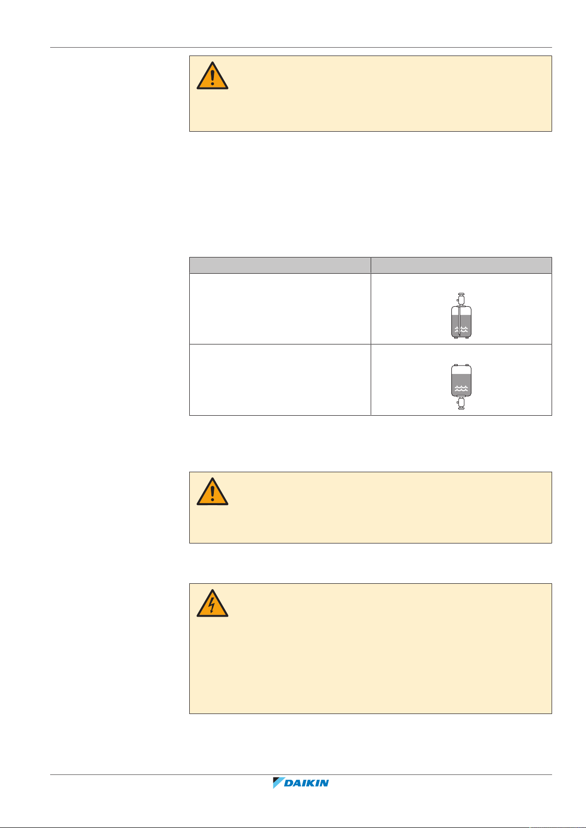
▪ Charge the liquid refrigerant as follows:
If Then
A siphon tube is present
Charge with the cylinder upright.
(i.e., the cylinder is marked with "Liquid
filling siphon attached")
A siphon tube is NOT present Charge with the cylinder upside down.
▪ Open refrigerant cylinders slowly.
▪ Charge the refrigerant in liquid form. Adding it in gas form may prevent normal
operation.
CAUTION
When the refrigerant charging procedure is done or when pausing, close the valve of
the refrigerant tank immediately. If the valve is NOT closed immediately, remaining
pressure might charge additional refrigerant. Possible consequence: Incorrect
refrigerant amount.
2.1.4 Electrical
FAA71+100BUV1B
Split system air conditioner
4P654517-1 – 2021.03
DANGER: RISK OF ELECTROCUTION
▪ Turn OFF all power supply before removing the switch box cover, connecting
electrical wiring or touching electrical parts.
▪ Disconnect the power supply for more than 10minutes, and measure the voltage
at the terminals of main circuit capacitors or electrical components before
servicing. The voltage MUST be less than 50VDC before you can touch electrical
components. For the location of the terminals, see the wiring diagram.
▪ Do NOT touch electrical components with wet hands.
▪ Do NOT leave the unit unattended when the service cover is removed.
Installer and user reference guide
13
2 | General safety precautions
WARNING
If NOT factory installed, a main switch or other means for disconnection, having a
contact separation in all poles providing full disconnection under overvoltage
categoryIII condition, MUST be installed in the fixed wiring.
WARNING
▪ ONLY use copper wires.
▪ Make sure the field wiring complies with the applicable legislation.
▪ All field wiring MUST be performed in accordance with the wiring diagram
supplied with the product.
▪ NEVER squeeze bundled cables and make sure they do NOT come in contact with
the piping and sharp edges. Make sure no external pressure is applied to the
terminal connections.
▪ Make sure to install earth wiring. Do NOT earth the unit to a utility pipe, surge
absorber, or telephone earth. Incomplete earth may cause electrical shock.
▪ Make sure to use a dedicated power circuit. NEVER use a power supply shared by
another appliance.
▪ Make sure to install the required fuses or circuit breakers.
▪ Make sure to install an earth leakage protector. Failure to do so may cause
electrical shock or fire.
▪ When installing the earth leakage protector, make sure it is compatible with the
inverter (resistant to high frequency electric noise) to avoid unnecessary opening
of the earth leakage protector.
CAUTION
▪ When connecting the power supply: connect the earth cable first, before making
the current-carrying connections.
▪ When disconnecting the power supply: disconnect the current-carrying cables
first, before separating the earth connection.
▪ The length of the conductors between the power supply stress relief and the
terminal block itself MUST be as such that the current-carrying wires are
tautened before the earth wire is in case the power supply is pulled loose from
the stress relief.
NOTICE
Precautions when laying power wiring:
▪ Do NOT connect wiring of different thicknesses to the power terminal block (slack
in the power wiring may cause abnormal heat).
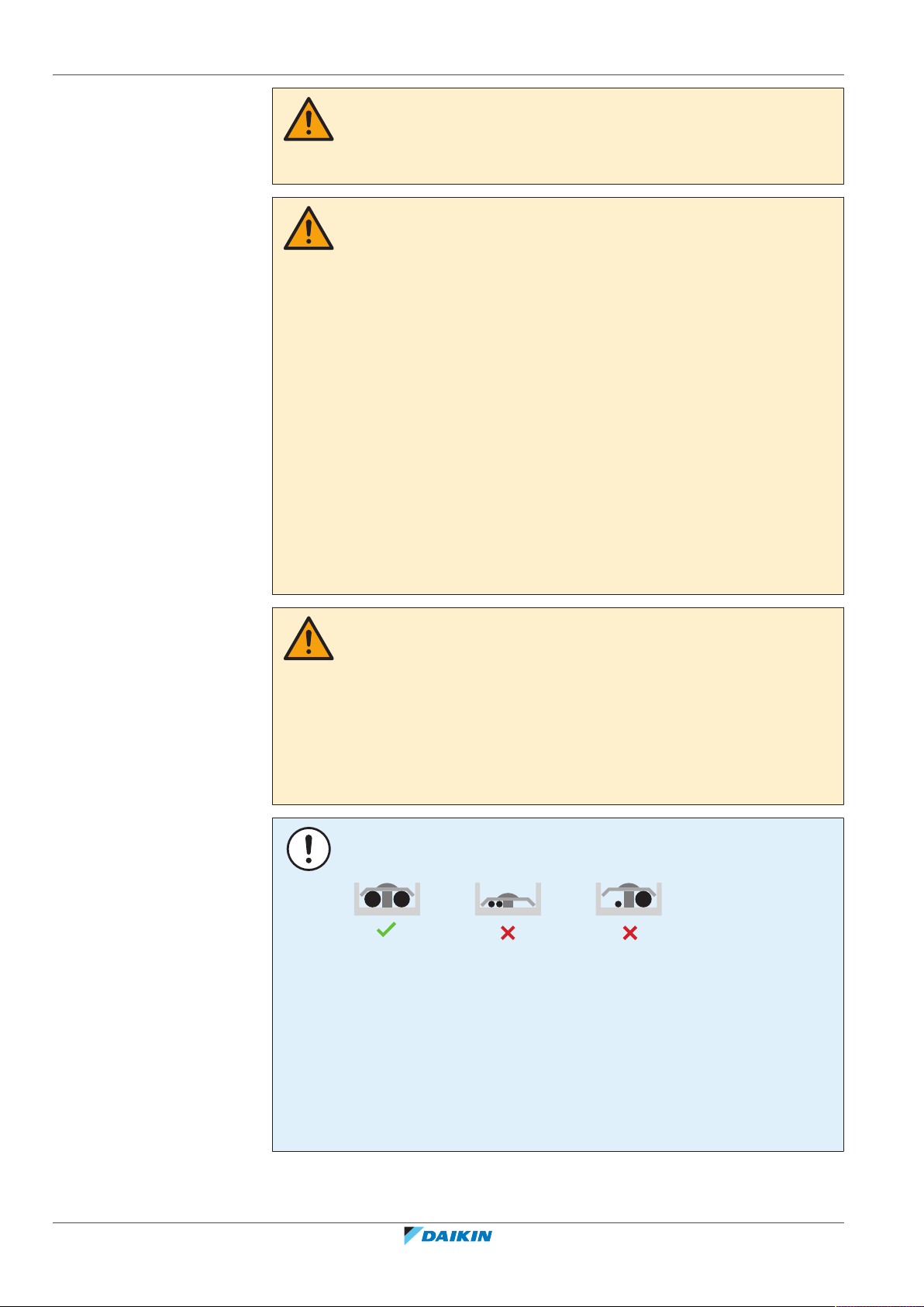
▪ When connecting wiring which is the same thickness, do as shown in the figure
above.
▪ For wiring, use the designated power wire and connect firmly, then secure to
prevent outside pressure being exerted on the terminal board.
▪ Use an appropriate screwdriver for tightening the terminal screws. A screwdriver
with a small head will damage the head and make proper tightening impossible.
▪ Over-tightening the terminal screws may break them.
Installer and user reference guide
14
FAA71+100BUV1B
Split system air conditioner
4P654517-1 – 2021.03
2 | General safety precautions
Install power cables at least 1 m away from televisions or radios to prevent
interference. Depending on the radio waves, a distance of 1 m may not be
sufficient.
WARNING
▪ After finishing the electrical work, confirm that each electrical component and
terminal inside the electrical components box is connected securely.
▪ Make sure all covers are closed before starting up the unit.
NOTICE
Only applicable if the power supply is three‑phase, and the compressor has an ON/
OFF starting method.
If there exists the possibility of reversed phase after a momentary black out and the
power goes on and off while the product is operating, attach a reversed phase
protection circuit locally. Running the product in reversed phase can break the
compressor and other parts.
FAA71+100BUV1B
Split system air conditioner
4P654517-1 – 2021.03
Installer and user reference guide
15
3 | Specific installer safety instructions
3 Specific installer safety instructions
Always observe the following safety instructions and regulations.
General
WARNING
Make sure installation, servicing, maintenance, repair and applied materials follow
the instructions from Daikin and, in addition, comply with applicable legislation and
are performed by qualified persons only. In Europe and areas where IEC standards
apply, EN/IEC 60335-2-40 is the applicable standard.
Unit installation (see
"16Unit installation"[450]
WARNING
The appliance using R32 refrigerant shall be stored so as to prevent mechanical
damage and in a well-ventilated room without continuously operating ignition
sources (e.g. open flames, an operating gas appliance, or an operating electric
heater). The room size shall be as specified in the General safety precaution.
CAUTION
For walls containing a metal frame or a metal board, use a wall embedded pipe and
wall cover in the feed-through hole to prevent possible heat, electrical shock, or fire.
Refrigerant piping installation (see
CAUTION
Piping MUST be installed according to instructions given in "17 Piping
installation" [4 62]. Only mechanical joints (e.g. braze+flare connections) that are
compliant with the latest version of ISO14903 can be used.
CAUTION
▪ Do NOT use mineral oil on flared part.
▪ Do NOT reuse piping from previous installations.
▪ NEVER install a drier to this unit to guarantee its lifetime. The drying material may
dissolve and damage the system.
)
"17Piping installation"[462]
)
Installer and user reference guide
16
CAUTION
▪ Incomplete flaring may cause refrigerant gas leakage.
▪ Do NOT re-use flares. Use new flares to prevent refrigerant gas leakage.
▪ Use flare nuts that are included with the unit. Using different flare nuts may
cause refrigerant gas leakage.
CAUTION
Install the refrigerant piping or components in a position where they are unlikely to
be exposed to any substance which may corrode components containing refrigerant,
unless the components are constructed of materials that are inherently resistant to
corrosion or are suitably protected against corrosion.
FAA71+100BUV1B
Split system air conditioner
4P654517-1 – 2021.03
3 | Specific installer safety instructions
Electrical installation (see
WARNING
▪ All wiring MUST be performed by an authorised electrician and MUST comply
with the applicable legislation.
▪ Make electrical connections to the fixed wiring.
▪ All components procured on-site and all electrical construction MUST comply
with the applicable legislation.
WARNING
▪ If the power supply has a missing or wrong N-phase, equipment might break
down.
▪ Establish proper earthing. Do NOT earth the unit to a utility pipe, surge absorber,
or telephone earth. Incomplete earthing may cause electrical shock.
▪ Install the required fuses or circuit breakers.
▪ Secure the electrical wiring with cable ties so that the cables do NOT come in
contact with sharp edges or piping, particularly on the high-pressure side.
▪ Do NOT use taped wires, stranded conductor wires, extension cords, or
connections from a star system. They can cause overheating, electrical shock or
fire.
▪ Do NOT install a phase advancing capacitor, because this unit is equipped with an
inverter. A phase advancing capacitor will reduce performance and may cause
accidents.
"18Electrical installation"[467]
)
WARNING
ALWAYS use multicore cable for power supply cables.
WARNING
Use an all-pole disconnection type breaker with at least 3mm between the contact
point gaps that provide full disconnection under overvoltage category III.
WARNING
If the supply cord is damaged, it MUST be replaced by the manufacturer, its service
agent or similarly qualified persons in order to avoid a hazard.
FAA71+100BUV1B
Split system air conditioner
4P654517-1 – 2021.03
Installer and user reference guide
17

For the user
For the user
Installer and user reference guide
18
FAA71+100BUV1B
Split system air conditioner
4P654517-1 – 2021.03
4 User safety instructions
Always observe the following safety instructions and regulations.
4.1 General
WARNING
If you are NOT sure how to operate the unit, contact your
installer.
WARNING
This appliance can be used by children aged from 8 years
and above and persons with reduced physical, sensory or
mental capabilities or lack of experience and knowledge if
they have been given supervision or instruction concerning
use of the appliance in a safe way and understand the
hazards involved.
4 | User safety instructions
Children SHALL NOT play with the appliance.
Cleaning and user maintenance SHALL NOT be made by
children without supervision.
WARNING
To prevent electrical shocks or fire:
▪ Do NOT rinse the unit.
▪ Do NOT operate the unit with wet hands.
▪ Do NOT place any objects containing water on the unit.
CAUTION
▪ Do NOT place any objects or equipment on top of the
unit.
▪ Do NOT sit, climb or stand on the unit.
FAA71+100BUV1B
Split system air conditioner
4P654517-1 – 2021.03
Installer and user reference guide
19
4 | User safety instructions
▪ Units are marked with the following symbol:
▪ Batteries are marked with the following symbol:
This means that electrical and electronic products may NOT be mixed with
unsorted household waste. Do NOT try to dismantle the system yourself: the
dismantling of the system, treatment of the refrigerant, of oil and of other parts
must be done by an authorized installer and must comply with applicable
legislation.
Units must be treated at a specialized treatment facility for reuse, recycling and
recovery. By ensuring this product is disposed of correctly, you will help to
prevent potential negative consequences for the environment and human
health. For more information, contact your installer or local authority.
This means that the batteries may NOT be mixed with unsorted household
waste. If a chemical symbol is printed beneath the symbol, this chemical symbol
means that the battery contains a heavy metal above a certain concentration.
Possible chemical symbols are: Pb: lead (>0.004%).
Waste batteries must be treated at a specialized treatment facility for reuse. By
ensuring waste batteries are disposed of correctly, you will help to prevent
potential negative consequences for the environment and human health.
4.2 Instructions for safe operation
WARNING
▪ Do NOT modify, disassemble, remove, reinstall or repair
the unit yourself as incorrect dismantling or installation
may cause an electric shock or fire. Contact your dealer.
▪ In case of accidental refrigerant leaks, make sure there
are no naked flames. The refrigerant itself is entirely
safe and non-toxic. R410A is a non-combustible
refrigerant, and R32 is a mildly flammable refrigerant,
but they will generate a toxic gas when they accidentally
leak into a room where combustible air from fan
heaters, gas cookers, etc. is present. Always have
qualified service personnel confirm that the point of
leakage has been repaired or corrected before resuming
operation.
Installer and user reference guide
20
FAA71+100BUV1B
Split system air conditioner
4P654517-1 – 2021.03
4 | User safety instructions
CAUTION
▪ NEVER touch the internal parts of the controller.
▪ Do NOT remove the front panel. Some parts inside are
dangerous to touch and appliance problems may
happen. For checking and adjusting the internal parts,
contact your dealer.
WARNING
This unit contains electrical and hot parts.
WARNING
Before operating the unit, be sure the installation has been
carried out correctly by an installer.
CAUTION
It is unhealthy to expose your body to the air flow for a
long time.
CAUTION
To avoid oxygen deficiency, ventilate the room sufficiently
if equipment with burner is used together with the system.
CAUTION
Do NOT operate the system when using a room
fumigation-type insecticide. Chemicals could collect in the
unit, and endanger the health of people who are
hypersensitive to chemicals.
CAUTION
▪ ALWAYS use a user interface to adjust the angle of the
flap. When the flap is swinging and you move it forcibly
by hand, the mechanism will break.
▪ Be careful when adjusting the louvers. Inside the air
outlet, a fan is rotating at high speed.
FAA71+100BUV1B
Split system air conditioner
4P654517-1 – 2021.03
CAUTION
NEVER expose little children, plants or animals directly to
the airflow.
Installer and user reference guide
21
4 | User safety instructions
WARNING
Do NOT place a flammable spray bottle near the air
conditioner and do NOT use sprays near the unit. Doing so
may result in a fire.
Maintenance and service (see
CAUTION: Pay attention to the fan!
It is dangerous to inspect the unit while the fan is running.
Be sure to turn off the main switch before executing any
maintenance task.
CAUTION
Do NOT insert fingers, rods or other objects into the air
inlet or outlet. When the fan is rotating at high speed, it
will cause injury.
WARNING
NEVER replace a fuse with a fuse of a wrong ampere
ratings or other wires when a fuse blows out. Use of wire
or copper wire may cause the unit to break down or cause
a fire.
"10Maintenance and service"[434]
)
CAUTION
After a long use, check the unit stand and fitting for
damage. If damaged, the unit may fall and result in injury.
CAUTION
Before accessing terminal devices, make sure to interrupt
all power supply.
DANGER: RISK OF ELECTROCUTION
To clean the air conditioner or air filter, be sure to stop
operation and turn all power supplies off. Otherwise, an
electric shock and injury may result.
WARNING
Be careful with ladders when working in high places.
CAUTION
Installer and user reference guide
22
Turn off the unit before cleaning the air outlet, exterior,
front panel and air filter.
FAA71+100BUV1B
Split system air conditioner
4P654517-1 – 2021.03
4 | User safety instructions
WARNING
Do NOT let the indoor unit get wet. Possible consequence:
Electric shock or fire.
About the refrigerant (see
WARNING: MILDLY FLAMMABLE MATERIAL
The R32 refrigerant (if applicable) in this unit is mildly
flammable. Refer to the outdoor unit specifications for the
type of refrigerant to be used.
WARNING
The appliance using R32 refrigerant shall be stored so as to
prevent mechanical damage and in a well-ventilated room
without continuously operating ignition sources (e.g. open
flames, an operating gas appliance, or an operating electric
heater). The room size shall be as specified in the General
safety precaution.
WARNING
▪ Do NOT pierce or burn refrigerant cycle parts.
▪ Do NOT use cleaning materials or means to accelerate
the defrosting process other than those recommended
by the manufacturer.
"10.5About the refrigerant"[438]
)
▪ Be aware that the refrigerant inside the system is
odourless.
WARNING
R410A is a non-combustible refrigerant, and R32 is a mildly
flammable refrigerant; they normally don’t leak. If the
refrigerant leaks in the room and comes into contact with
fire from a burner, a heater, or a cooker, this may result in
a fire (in case of R32), or the formation of a harmful gas.
Turn off any combustible heating devices, ventilate the
room, and contact the dealer from where you purchased
the unit.
Do not use the unit until a service person confirms that the
part from which the refrigerant leaked has been repaired.
FAA71+100BUV1B
Split system air conditioner
4P654517-1 – 2021.03
Installer and user reference guide
23
4 | User safety instructions
Troubleshooting (see
WARNING
Stop operation and shut off the power if anything
unusual occurs (burning smells etc.).
Leaving the unit running under such circumstances may
cause breakage, electric shock or fire. Contact your dealer.
"11Troubleshooting"[439]
)
Installer and user reference guide
24
FAA71+100BUV1B
Split system air conditioner
4P654517-1 – 2021.03
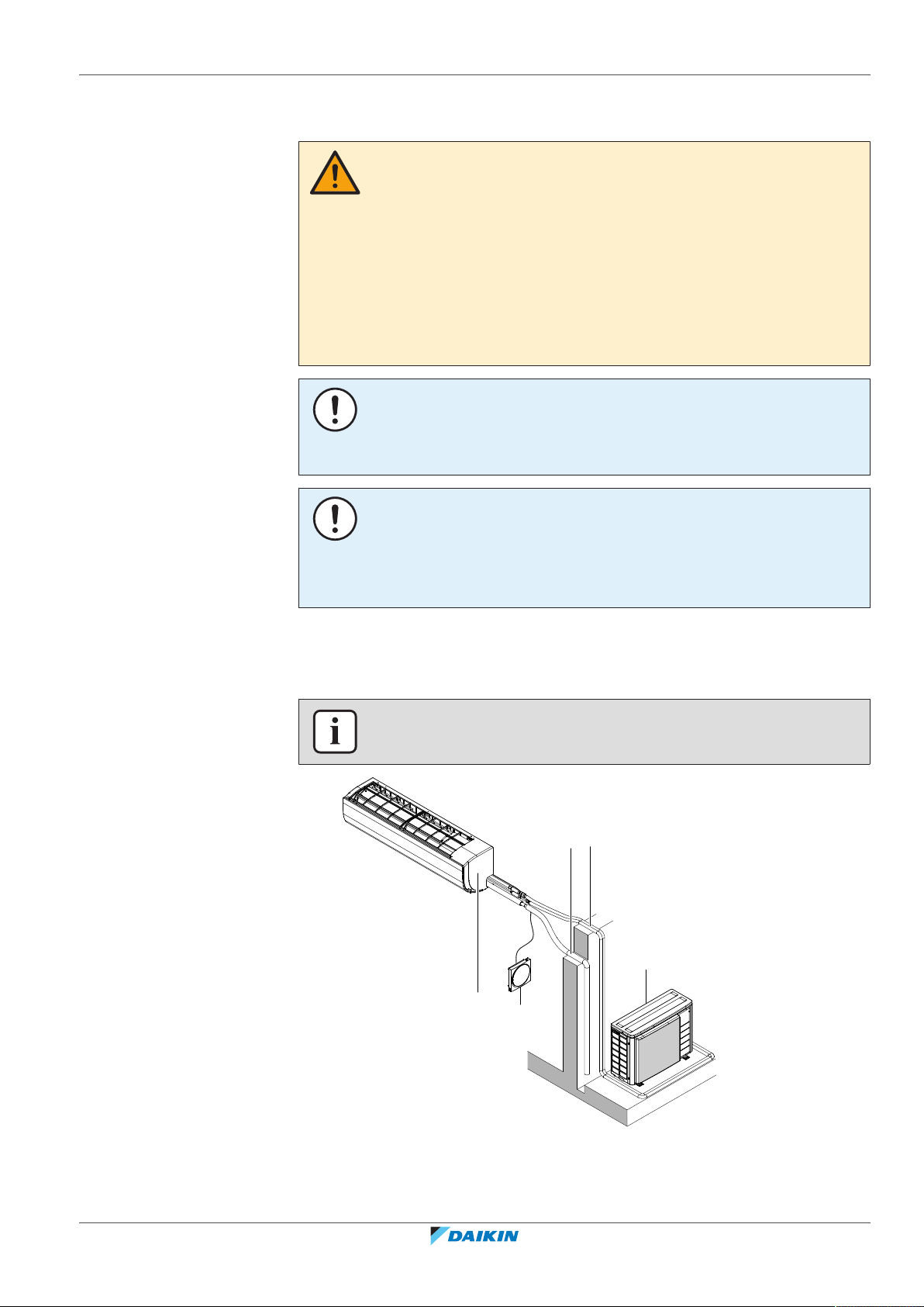
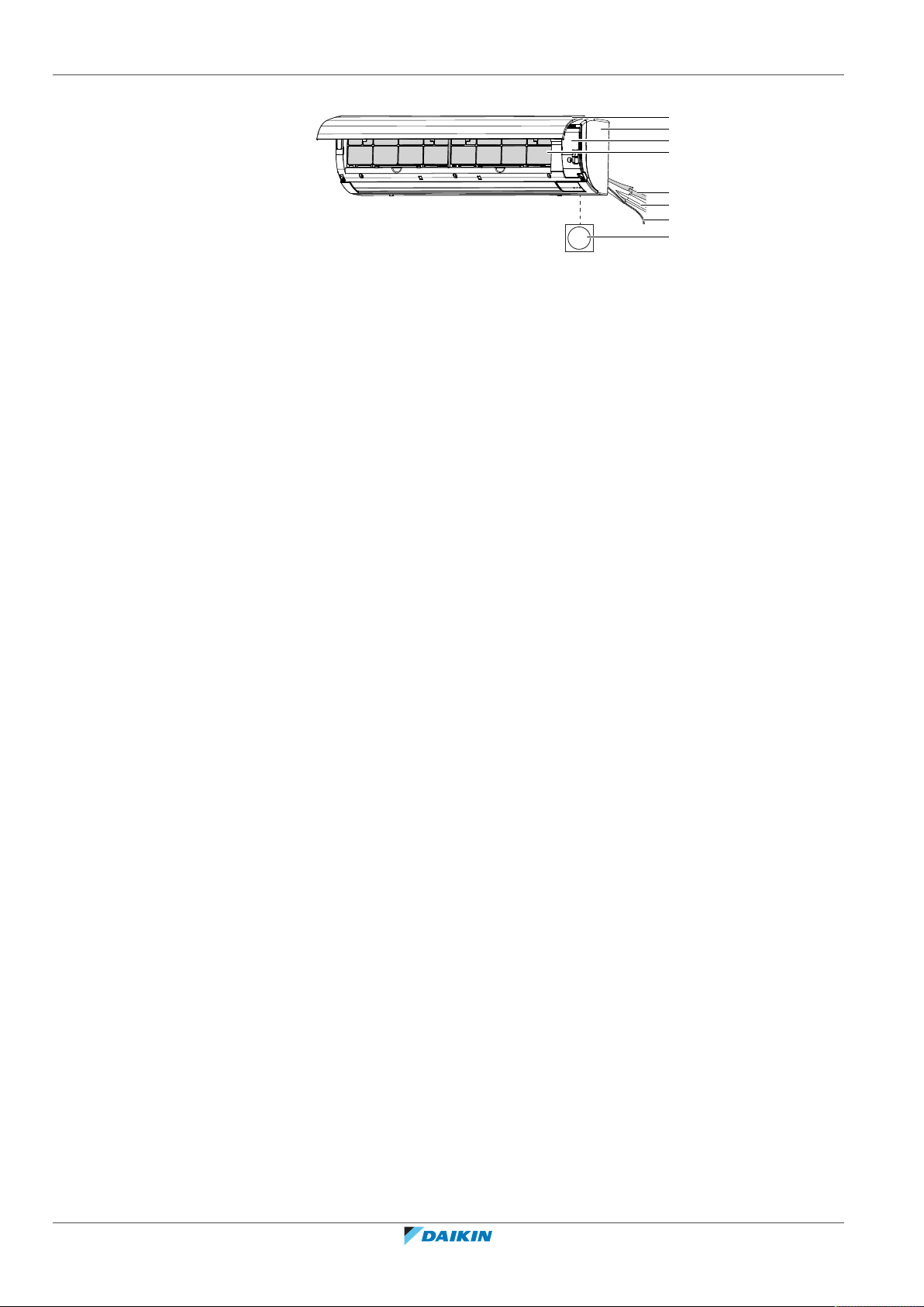
5 About the system
b
c
a
d
e
WARNING
▪ Do NOT modify, disassemble, remove, reinstall or repair the unit yourself as
incorrect dismantling or installation may cause an electric shock or fire. Contact
your dealer.
▪ In case of accidental refrigerant leaks, make sure there are no naked flames. The
refrigerant itself is entirely safe and non-toxic. R410A is a non-combustible
refrigerant, and R32 is a mildly flammable refrigerant, but they will generate a
toxic gas when they accidentally leak into a room where combustible air from fan
heaters, gas cookers, etc. is present. Always have qualified service personnel
confirm that the point of leakage has been repaired or corrected before resuming
operation.
NOTICE
Do NOT use the system for other purposes. In order to avoid any quality
deterioration, do NOT use the unit for cooling precision instruments, food, plants,
animals, or works of art.
NOTICE
For future modifications or expansions of your system:
A full overview of allowable combinations (for future system extensions) is available
in technical engineering data and should be consulted. Contact your installer to
receive more information and professional advice.
5 | About the system
5.1 System layout
INFORMATION
The following illustration is an example and might NOT match your system layout.
FAA71+100BUV1B
Split system air conditioner
4P654517-1 – 2021.03
a Indoor unit
b Outdoor unit
c User interface
d Refrigerant piping + trasmission cable
Installer and user reference guide
25
5 | About the system
a
c
d
b
e
f
g
h
e Drain pipe
a Front panel
b Front grille
c Service cover
d Air filters
e Drain hose
f Refrigerant pipes
g Electrical wiring
h User interface
Installer and user reference guide
26
FAA71+100BUV1B
Split system air conditioner
4P654517-1 – 2021.03
6 User interface
CAUTION
▪ NEVER touch the internal parts of the controller.
▪ Do NOT remove the front panel. Some parts inside are dangerous to touch and
NOTICE
Do NOT wipe the controller operation panel with benzine, thinner, chemical dust
cloth, etc. The panel may get discoloured or the coating peeled off. If it is heavily
dirty, soak a cloth in water-diluted neutral detergent, squeeze it well and wipe the
panel clean. Wipe it with another dry cloth.
NOTICE
NEVER press the button of the user interface with a hard, pointed object. The user
interface may be damaged.
6 | User interface
appliance problems may happen. For checking and adjusting the internal parts,
contact your dealer.
NOTICE
NEVER pull or twist the electric wire of the user interface. It may cause the unit to
malfunction.
This operation manual offers a non-exhaustive overview of the main functions of
the system.
For more information about the user interface, see the operation manual of the
installed user interface.
FAA71+100BUV1B
Split system air conditioner
4P654517-1 – 2021.03
Installer and user reference guide
27
7 | Before operation
7 Before operation
WARNING
This unit contains electrical and hot parts.
WARNING
Before operating the unit, be sure the installation has been carried out correctly by
an installer.
CAUTION
It is unhealthy to expose your body to the air flow for a long time.
CAUTION
To avoid oxygen deficiency, ventilate the room sufficiently if equipment with burner
is used together with the system.
CAUTION
Do NOT operate the system when using a room fumigation-type insecticide.
Chemicals could collect in the unit, and endanger the health of people who are
hypersensitive to chemicals.
NOTICE
Be sure to turn ON the power 6 hours before operation in order to have power
running to the crankcase heater and to protect the compressor.
This operation manual is for the following systems with standard control. Before
initiating operation, contact your dealer for the operation that corresponds to your
system type and mark. If your installation has a customised control system, ask
your dealer for the operation that corresponds to your system.
Installer and user reference guide
28
FAA71+100BUV1B
Split system air conditioner
4P654517-1 – 2021.03

8 Operation
8.1 Operation range
Use the system in the following temperature and humidity ranges for safe and
effective operation.
For combination with R410A outdoor unit, refer to the following table:
Outdoor units Cooling Heating
8 | Operation
RZQ200 Outdoor
–5~46°C DB –15~15°C WB
temperature
Indoor
14~28°C WB 10~27°C DB
temperature
RZQG71~140 Outdoor
–15~50°C DB –20~15.5°C WB
temperature
Indoor
12~28°C WB 10~27°C DB
temperature
RZQSG71~140 Outdoor
–15~46°C DB –15~15.5°C WB
temperature
Indoor
14~28°C WB 10~27°C DB
temperature
Indoor humidity ≤80%
(a)
To avoid condensation and water dripping out of the unit. If the temperature or the
humidity is beyond these conditions, safety devices may be put in action and the air
conditioner may not operate.
(a)
For combination with R32 outdoor unit, refer to the following table:
Outdoor units Cooling Heating
RZAG71~140 Outdoor
temperature
–20~52°C DB –20~24°C DB
–20~18°C WB
—
FAA71+100BUV1B
Split system air conditioner
4P654517-1 – 2021.03
Indoor
temperature
RZASG71~140 Outdoor
temperature
Indoor
temperature
AZAS71+100 Outdoor
temperature
Indoor
temperature
RZA200+250 Outdoor
temperature
Indoor
temperature
17~38°C DB
10~27°C DB
12~28°C WB
–15~46°C DB –15~21°C DB
–15~15.5°C WB
20~38°C DB
10~27°C DB
14~28°C WB
–5~46°C DB –15~21°C DB
–15~15.5°C WB
20~38°C DB
10~27°C DB
14~28°C WB
-20~46°C DB -20~15°C WB
14~28°C WB 10~27°C DB
Installer and user reference guide
29

8 | Operation
Outdoor units Cooling Heating
ARXM71 Outdoor
Indoor humidity ≤80%
(a)
To avoid condensation and water dripping out of the unit. If the temperature or the
humidity is beyond these conditions, safety devices may be put in action and the air
conditioner may not operate.
DB: Dry bulb
WB: Wet bulb
8.2 About operation modes
INFORMATION
Depending on the installed system, some operation modes will not be available.
▪ The air flow rate may adjust itself depending on the room temperature or the fan
may stop immediately. This is not a malfunction.
temperature
Indoor
temperature
-10~46°C DB -15~18°C WB
14~28°C WB 10~30°C DB
(a)
—
▪ If the main power supply is turned off during operation, operation will restart
automatically after the power turns back on again.
▪ Setpoint. Target temperature for the Cooling, Heating, and Auto operation
modes.
▪ Setback. A function that keeps the room temperature in a specific range when
the system is turned off (by the user, the schedule function, or the OFF timer).
8.2.1 Basic operation modes
The indoor unit can operate in various operation modes.
Icon Operation mode
Cooling. In this mode, cooling will be activated as required by the
setpoint, or by Setback operation.
Heating. In this mode, heating will be activated as required by
the setpoint, or by Setback operation.
Fan only. In this mode, air circulates without heating or cooling.
Dry. In this mode, the air humidity will be lowered with a
minimal temperature decrease.
The temperature and fan speed are controlled automatically and
cannot be controlled by the controller.
Installer and user reference guide
30
Dry operation will not function if the room temperature is too
low.
Auto. In Auto mode, the indoor unit automatically switches
between heating and cooling mode, as required by the setpoint.
FAA71+100BUV1B
Split system air conditioner
4P654517-1 – 2021.03

8.2.2 Special heating operation modes
Operation Description
Defrost To prevent a loss of heating capacity
Hot start During hot start, the indoor unit fan will
8 | Operation
due to frost accumulation in the
outdoor unit, the system will
automatically switch to defrost
operation.
During defrost operation, the indoor
unit fan will stop operation, and the
following icon will appear on the home
screen:
The system will resume normal
operation after approximately 6 to 8
minutes.
stop operation, and the following icon
will appear on the home screen:
8.2.3 Airflow direction
When. Adjust the airflow direction as desired.
What. The system directs the airflow differently, depending on the user selection.
The following vertical airflow directions can be set by the user interface:
CAUTION
▪ ALWAYS use a user interface to adjust the angle of the flap. When the flap is
swinging and you move it forcibly by hand, the mechanism will break.
▪ Be careful when adjusting the louvers. Inside the air outlet, a fan is rotating at
high speed.
1 Vertical airflow
Direction Screen
Fixed position. The indoor unit blows
air in 1 of 5 fixed positions.
Swing. The indoor unit alternates
between the 5 positions.
FAA71+100BUV1B
Split system air conditioner
4P654517-1 – 2021.03
Note: Recommended position of the horizontal blades (flaps) varies according to
the operation mode.
Installer and user reference guide
31

8 | Operation
a
b
aa
a Cooling operation
b Heating operation
INFORMATION
For setting procedure of the vertical airflow direction, see the reference guide or the
manual of the used user interface.
2 Horizontal airflow
▪ Horizontal airflow: by manually adjusting position of the vertical blades (louvers).
To adjust the louvers (vertical blades)
1 Adjust horizontal blades using the user interface so you can easily access the
knobs on the vertical blades.
2 Hold knobs and move them down slightly.
3 Adjust left or right to the desired position while holding the knobs.
a Knobs
INFORMATION
When the unit is installed in a corner of a room, the direction of the louvers should
be facing away from the wall. Efficiency will drop if a wall blocks the air.
8.3 To operate the system
INFORMATION
For setting of the operation mode or other settings, see the reference guide or
operation manual of the user interface.
Installer and user reference guide
32
FAA71+100BUV1B
Split system air conditioner
4P654517-1 – 2021.03

9 | Energy saving and optimum operation
9 Energy saving and optimum operation
CAUTION
NEVER expose little children, plants or animals directly to the airflow.
NOTICE
Do NOT place objects below the indoor and/or outdoor unit that may get wet.
Otherwise condensation on the unit or refrigerant pipes, air filter dirt or drain
blockage may cause dripping, and objects under the unit may get dirty or damaged.
WARNING
Do NOT place a flammable spray bottle near the air conditioner and do NOT use
sprays near the unit. Doing so may result in a fire.
Observe the following precautions to ensure the system operates properly.
▪ Prevent direct sunlight from entering a room during cooling operation by using
curtains or blinds.
▪ Make sure the area is well ventilated. Do NOT block any ventilation openings.
▪ Ventilate often. Extended use requires special attention to ventilation.
▪ Keep doors and windows closed. If the doors and windows remain open, air will
flow out of your room causing a decrease in the cooling or heating effect.
▪ Be careful NOT to cool or heat too much. To save energy, keep the temperature
setting at a moderate level.
▪ NEVER place objects near the air inlet or the air outlet of the unit. Doing so may
cause a reduced heating/cooling effect or stop operation.
▪ When the display shows (time to clean the air filter), clean the filters (see
"10.2.3To clean the air filter"[436]).
▪ Condensation may form if the humidity is above 80% or if the drain outlet gets
blocked.
▪ Adjust the air outlet properly and avoid direct air flow to room inhabitants.
FAA71+100BUV1B
Split system air conditioner
4P654517-1 – 2021.03
Installer and user reference guide
33

10 | Maintenance and service
10 Maintenance and service
10.1 Precautions for maintenance and service
NOTICE
Maintenance MUST be done by an authorized installer or service agent.
We recommend performing maintenance at least once a year. However, applicable
legislation might require shorter maintenance intervals.
CAUTION: Pay attention to the fan!
It is dangerous to inspect the unit while the fan is running.
Be sure to turn off the main switch before executing any maintenance task.
CAUTION
Do NOT insert fingers, rods or other objects into the air inlet or outlet. When the fan
is rotating at high speed, it will cause injury.
NOTICE
NEVER inspect or service the unit by yourself. Ask a qualified service person to
perform this work. However, as end user, you may clean the air outlet, exterior, front
panel and air filter.
WARNING
NEVER replace a fuse with a fuse of a wrong ampere ratings or other wires when a
fuse blows out. Use of wire or copper wire may cause the unit to break down or
cause a fire.
CAUTION
After a long use, check the unit stand and fitting for damage. If damaged, the unit
may fall and result in injury.
CAUTION
Before accessing terminal devices, make sure to interrupt all power supply.
DANGER: RISK OF ELECTROCUTION
To clean the air conditioner or air filter, be sure to stop operation and turn all power
supplies off. Otherwise, an electric shock and injury may result.
Installer and user reference guide
34
WARNING
Be careful with ladders when working in high places.
Following symbols may occur on the indoor unit:
Symbol Explanation
Measure the voltage at the terminals of main circuit capacitors or
electrical components before servicing.
FAA71+100BUV1B
Split system air conditioner
4P654517-1 – 2021.03
10.2 Cleaning the unit
a
CAUTION
Turn off the unit before cleaning the air outlet, exterior, front panel and air filter.
10.2.1 To clean the air outlet and exterior
WARNING
Do NOT let the indoor unit get wet. Possible consequence: Electric shock or fire.
NOTICE
▪ Do NOT use gasoline, benzene, thinner polishing powder or liquid insecticide.
Possible consequence: Discoloration and deformation.
▪ Do NOT use water or air of 50°C or higher. Possible consequence: Discoloration
and deformation.
▪ Do NOT scrub firmly when washing the blade with water. Possible consequence:
The surface sealing peels off.
10 | Maintenance and service
Clean with a soft cloth. If it is difficult to remove stains, use water or neutral
detergent.
10.2.2 To clean the front panel
You can remove the front panel to clean it.
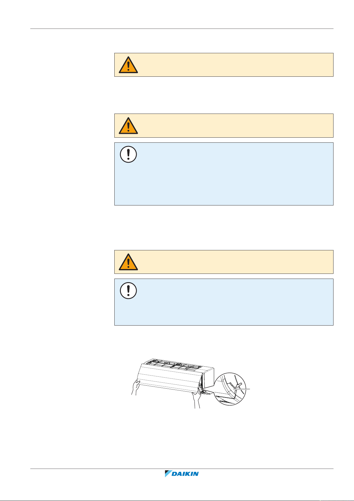
1 Open the front panel. Hold the front panel by the panel tabs on both sides and
open until the panel stops.
WARNING
Do NOT let the indoor unit get wet. Possible consequence: Electric shock or fire.
NOTICE
▪ Do NOT use gasoline, benzene, thinner polishing powder or liquid insecticide.
Possible consequence: Discoloration and deformation.
▪ Do NOT use water or air of 50°C or higher. Possible consequence: Discoloration
and deformation.
FAA71+100BUV1B
Split system air conditioner
4P654517-1 – 2021.03
a Panel tab
2 Remove the front panel by pushing hooks on either side of the front panel
towards the side of the unit and remove the panel.
Installer and user reference guide
35

10 | Maintenance and service
a
3 Clean the front panel. Wipe it with a soft cloth soaked in water by using only
4 Wipe panel with a dry soft cloth and let it dry up in the shade.
5 Attach the front panel. Align the hooks of the front panel with the slots and
neutral detergent.
push them all the way in.
6 Close the front panel slowly.
10.2.3 To clean the air filter
When to clean the air filter:
▪ Rule of thumb: Clean every 6 months. If the air in the room is extremely
contaminated, increase the cleaning frequency.
▪ Depending on the settings, the user interface can display the "Time to clean
filter" notification. Clean the air filter when the notification is displayed.
▪ If the dirt becomes impossible to clean, change the air filter (= optional
equipment).
How to clean the air filter:
1 Open the front panel. Hold the front panel by the panel tabs on both sides
and open until the panel stops.
NOTICE
Do NOT use water of 50°C or higher. Possible consequence: Discoloration and
deformation.
Installer and user reference guide
36
a Panel tab
2 Remove the air filter. Push up the tab in the center of the air filter slightly
then pull the air filter out in a downward direction.
FAA71+100BUV1B
Split system air conditioner
4P654517-1 – 2021.03
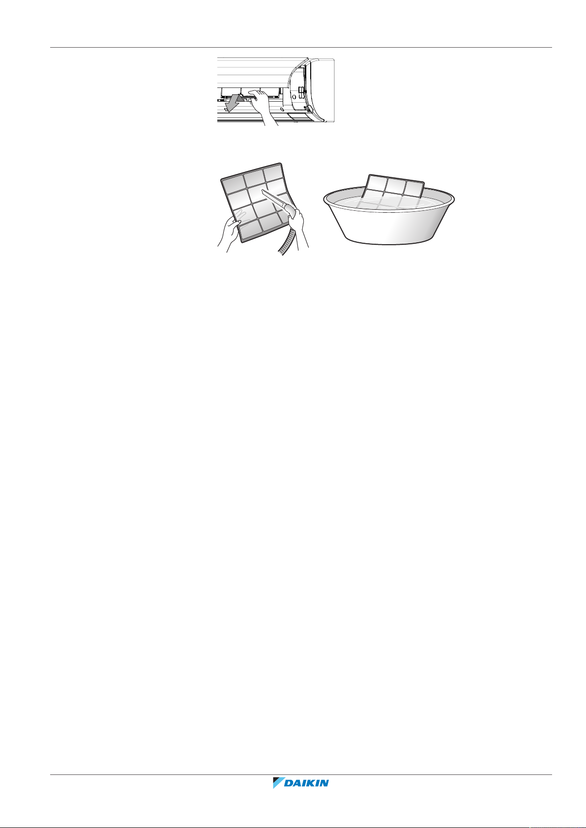
10 | Maintenance and service
3 Clean the air filter. Use a vacuum cleaner or wash with water. If the air filter is
very dirty, use a soft brush and neutral detergent.
4 Dry the air filter in the shadow.
5 Reattach the air filter. Replace the air filter as it was.
6 Close the front panel. Hold the front panel by the panel tabs on both sides
and close it slowly.
7 Turn ON the power.
8 To remove warning screens, see the reference guide of the user interface.
10.3 Maintenance before a long stop period
E.g., at the end of the season.
▪ Let the indoor units run in fan only operation for about half a day in order to dry
the interior of the units.
▪ Clean air filters and casings of indoor units (see "10.2Cleaning the unit"[435]).
▪ Turn off the power. The user interface display disappears. When the main power
is turned on, the air conditioner will use some power, even if it is not operating.
▪ Remove the batteries from the user interface (if applicable).
10.4 Maintenance after a long stop period
E.g., at the beginning of the season.
▪ Check and remove everything that might be blocking inlet and outlet vents of
indoor units and outdoor units.
FAA71+100BUV1B
Split system air conditioner
4P654517-1 – 2021.03
▪ Clean air filters and casings of indoor units (see "10.2Cleaning the unit"[435]).
▪ Insert batteries in the user interface (if applicable).
▪ Turn on the power at least 6 hours before operating the unit in order to ensure
smoother operation. As soon as the power is turned on, the user interface
display appears.
Installer and user reference guide
37
10 | Maintenance and service
10.5 About the refrigerant
This product contains fluorinated greenhouse gases. Do NOT vent gases into the
atmosphere.
Refrigerant type: R32
Global warming potential (GWP) value: 675
Refrigerant type: R410A
Global warming potential (GWP) value: 2087.5
NOTICE
Applicable legislation on fluorinated greenhouse gases requires that the refrigerant
charge of the unit is indicated both in weight and CO2 equivalent.
Formula to calculate the quantity in CO2 equivalent tonnes: GWP value of the
refrigerant × total refrigerant charge [in kg] / 1000
Please contact your installer for more information.
WARNING: MILDLY FLAMMABLE MATERIAL
The R32 refrigerant (if applicable) in this unit is mildly flammable. Refer to the
outdoor unit specifications for the type of refrigerant to be used.
WARNING
The appliance using R32 refrigerant shall be stored so as to prevent mechanical
damage and in a well-ventilated room without continuously operating ignition
sources (e.g. open flames, an operating gas appliance, or an operating electric
heater). The room size shall be as specified in the General safety precaution.
WARNING
▪ Do NOT pierce or burn refrigerant cycle parts.
▪ Do NOT use cleaning materials or means to accelerate the defrosting process
other than those recommended by the manufacturer.
▪ Be aware that the refrigerant inside the system is odourless.
WARNING
R410A is a non-combustible refrigerant, and R32 is a mildly flammable refrigerant;
they normally don’t leak. If the refrigerant leaks in the room and comes into contact
with fire from a burner, a heater, or a cooker, this may result in a fire (in case of R32),
or the formation of a harmful gas.
Turn off any combustible heating devices, ventilate the room, and contact the dealer
from where you purchased the unit.
Do not use the unit until a service person confirms that the part from which the
refrigerant leaked has been repaired.
Installer and user reference guide
38
FAA71+100BUV1B
Split system air conditioner
4P654517-1 – 2021.03

11 Troubleshooting
If one of the following malfunctions occur, take the measures shown below and
contact your dealer.
WARNING
Stop operation and shut off the power if anything unusual occurs (burning smells
etc.).
Leaving the unit running under such circumstances may cause breakage, electric
shock or fire. Contact your dealer.
The system MUST be repaired by a qualified service person.
11 | Troubleshooting
Malfunction Measure
If a safety device such as a fuse, a circuit breaker
or a residual current device frequently actuates
Turn OFF all main power supply
switches to the unit.
or the ON/OFF switch does NOT function
properly.
If water leaks from the unit. Stop operation.
The operation switch does NOT function
Turn OFF the power supply.
properly.
If the user interface displays . Notify your installer and report
the error code. To display an
error code see the reference
guide of the user interface.
If the system does NOT operate properly except for the above mentioned cases
and none of the above mentioned malfunctions is evident, investigate the system
in accordance with the following procedures.
Malfunction Measure
If the system does not
operate at all.
▪ Check if there is no power failure. Wait until
power is restored. If power failure occurs during
operation, the system automatically restarts
immediately after power is restored.
▪ Check if no fuse has blown or breaker is activated.
Change the fuse or reset the breaker if necessary.
FAA71+100BUV1B
Split system air conditioner
4P654517-1 – 2021.03
Installer and user reference guide
39
11 | Troubleshooting
Malfunction Measure
The system operates but
cooling or heating is
insufficient.
▪ Check if air inlet or outlet of outdoor or indoor
unit is not blocked by obstacles. Remove any
obstacles and make sure the air can flow freely.
▪ Check if the air filter is not clogged (see "10.2.3To
clean the air filter"[436]).
▪ Check the temperature setting.
▪ Check the fan speed setting on your user
interface.
▪ Check for open doors or windows. Close doors and
windows to prevent wind from coming in.
▪ Check if there are too many occupants in the room
during cooling operation. Check if the heat source
of the room is excessive.
▪ Check if direct sunlight enters the room. Use
curtains or blinds.
▪ Check if the air flow angle is proper.
If after checking all above items, it is impossible to fix the problem yourself, contact
your installer and state the symptoms, the complete model name of the unit (with
manufacturing number if possible) and the installation date (possibly listed on the
warranty card).
11.1 Symptoms that are NOT system malfunctions
The following symptoms are NOT system malfunctions:
11.1.1 Symptom: The system does not operate
▪ The air conditioner does not start immediately after the ON/OFF button on the
user interface is pressed. If the operation lamp lights, the system is in normal
condition. To prevent overloading of the compressor motor, the air conditioner
starts 5 minutes after it is turned ON again in case it was turned OFF just before.
The same starting delay occurs after the operation mode selector button was
used.
▪ The system does not start immediately after the power supply is turned on. Wait
one minute until the micro computer is prepared for operation.
11.1.2 Symptom: The fan speed does not correspond to the setting
The fan speed does not change even if the fan speed adjustment button in
pressed. During heating operation, when the room temperature reaches the set
temperature, the outdoor unit goes off and the indoor unit changes to whisper fan
speed. This is to prevent cold air blowing directly on occupants of the room. The
fan speed will not change if the button is pressed.
11.1.3 Symptom: The fan direction does not correspond to the setting
Installer and user reference guide
40
The fan direction does not correspond with the user interface display. The fan
direction does not swing. This is because the unit is being controlled by the micro
computer.
FAA71+100BUV1B
Split system air conditioner
4P654517-1 – 2021.03

11 | Troubleshooting
11.1.4 Symptom: White mist comes out of a unit (Indoor unit)
▪ When humidity is high during cooling operation (in oily and dusty places). If the
interior of an indoor unit is extremely contaminated, the temperature
distribution inside a room becomes uneven. It is necessary to clean the interior
of the indoor unit. Ask your dealer for details on cleaning the unit. This operation
requires a qualified service person.
▪ When the air conditioner is changed over to heating operation after defrost
operation. Moisture generated by defrost becomes steam and exits.
11.1.5 Symptom: White mist comes out of a unit (Indoor unit, outdoor unit)
When the system is changed over to heating operation after defrost operation.
Moisture generated by defrost becomes steam and is exhausted.
11.1.6 Symptom: The user interface reads "U4" or "U5" and stops, but then restarts after a few minutes
This is because the user interface is intercepting noise from electric appliances
other than the air conditioner. The noise prevents communication between the
units, causing them to stop. Operation automatically restarts when the noise
ceases.
11.1.7 Symptom: Noise of air conditioners (Indoor unit)
▪ A "zeen" sound is heard immediately after the power supply is turned on. The
electronic expansion valve inside an indoor unit starts working and makes the
noise. Its volume will reduce in about one minute.
▪ A "pishi-pishi" squeaking sound is heard when the system stops after heating
operation. Expansion and contraction of plastic parts caused by temperature
change make this noise.
11.1.8 Symptom: Noise of air conditioners (Indoor unit, outdoor unit)
▪ A continuous low hissing sound is heard when the system is in cooling or defrost
operation. This is the sound of refrigerant gas flowing through both indoor and
outdoor units.
▪ A hissing sound which is heard at the start or immediately after stopping
operation or defrost operation. This is the noise of refrigerant caused by flow
stop or flow change.
11.1.9 Symptom: Dust comes out of the unit
When the unit is used for the first time in a long time. This is because dust has
gotten into the unit.
11.1.10 Symptom: The units can give off odours
The unit can absorb the smell of rooms, furniture, cigarettes, etc., and then emit it
again.
FAA71+100BUV1B
Split system air conditioner
4P654517-1 – 2021.03
Installer and user reference guide
41

12 | Relocation
12 Relocation
Contact your dealer for removing and reinstalling the total unit. Moving units
requires technical expertise.
Installer and user reference guide
42
FAA71+100BUV1B
Split system air conditioner
4P654517-1 – 2021.03

13 Disposal
13 | Disposal
NOTICE
Do NOT try to dismantle the system yourself: dismantling of the system, treatment of
the refrigerant, oil and other parts MUST comply with applicable legislation. Units
MUST be treated at a specialised treatment facility for reuse, recycling and recovery.
FAA71+100BUV1B
Split system air conditioner
4P654517-1 – 2021.03
Installer and user reference guide
43

For the installer
For the installer
Installer and user reference guide
44
FAA71+100BUV1B
Split system air conditioner
4P654517-1 – 2021.03
14 About the box
14.1 Overview: About the box
This chapter describes what you have to do after the box with the indoor unit is
delivered on-site.
It contains information about:
▪ Unpacking and handling the unit
▪ Removing the accessories from the unit
Keep the following in mind:
▪ At delivery, the unit MUST be checked for damage. Any damage MUST be
reported immediately to the claims agent of the carrier.
▪ Bring the packed unit as close as possible to its final installation position to
prevent damage during transport.
▪ Prepare the path along which you want to bring the unit inside in advance.
14 | About the box
14.2 Indoor unit
WARNING: MILDLY FLAMMABLE MATERIAL
The R32 refrigerant (if applicable) in this unit is mildly flammable. Refer to the
outdoor unit specifications for the type of refrigerant to be used.
▪ At delivery, the unit MUST be checked for damage. Any damage MUST be
reported immediately to the claims agent of the carrier.
▪ Bring the packed unit as close as possible to its final installation position to
prevent damage during transport.
▪ Unpack the indoor unit completely according to the instructions mentioned on
the unpacking instructions sheet.
14.2.1 To unpack and handle the unit
Use a sling of soft material or protective plates together with a rope when lifting
the unit. This to avoid damage or scratches to the unit.
1 Lift the unit by holding on to the hanger brackets without exerting any
pressure on other parts, especially on refrigerant piping, drain piping and
other resin parts.
FAA71+100BUV1B
Split system air conditioner
4P654517-1 – 2021.03
Installer and user reference guide
45
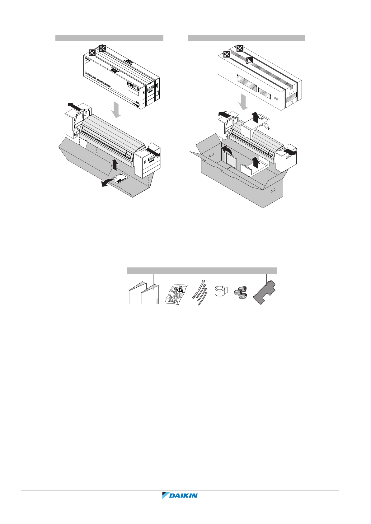
14 | About the box
FAA71 FAA100
1×1× 1× 4× 1× 3× 1×
cba d e f g
14.2.2 To remove the accessories from the indoor unit
1 Remove:
▪ the accessory bag located at the bottom of the package,
▪ the mounting plate attached to the back of the indoor unit.
a Installation and operation manual
b General safety precautions
c Fixing screws M4×25L for the mounting plate (9×), securing screws M4×12L (2× for
71 class, 3× for 100 class)
d Tie wraps (1 large, 3 small)
e Insulation tape
f Screws cover (for 100 class only)
g Mounting plate
Installer and user reference guide
46
FAA71+100BUV1B
Split system air conditioner
4P654517-1 – 2021.03
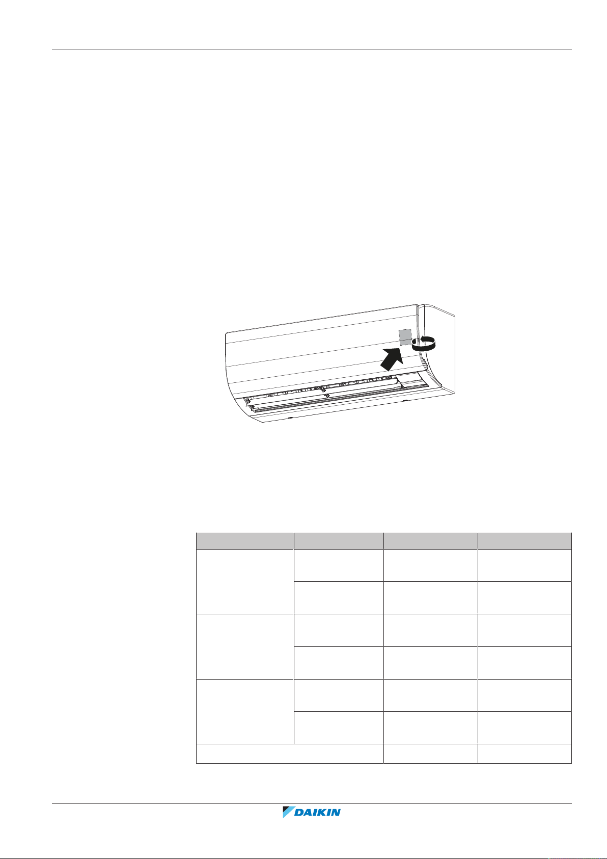
15 About the units and options
In this chapter
15.1 Identification........................................................................................................................................................................... 47
15.1.1 Identification label: Indoor unit............................................................................................................................. 47
15.2 About the indoor unit ............................................................................................................................................................. 47
15.3 System layout.......................................................................................................................................................................... 48
15.4 Combining units and options.................................................................................................................................................. 49
15.4.1 Possible options for the indoor unit...................................................................................................................... 49
15.1 Identification
15.1.1 Identification label: Indoor unit
Location
15 | About the units and options
15.2 About the indoor unit
Use the system in the following temperature and humidity ranges for safe and
effective operation.
For combination with R410A outdoor unit, refer to the following table:
Outdoor units Cooling Heating
RZQ200 Outdoor
RZQG71~140 Outdoor
RZQSG71~140 Outdoor
Indoor humidity ≤80%
temperature
Indoor
temperature
temperature
Indoor
temperature
temperature
Indoor
temperature
–5~46°C DB –15~15°C WB
14~28°C WB 10~27°C DB
–15~50°C DB –20~15.5°C WB
12~28°C WB 10~27°C DB
–15~46°C DB –15~15.5°C WB
14~28°C WB 10~27°C DB
(a)
—
FAA71+100BUV1B
Split system air conditioner
4P654517-1 – 2021.03
Installer and user reference guide
47

15 | About the units and options
(a)
To avoid condensation and water dripping out of the unit. If the temperature or the
humidity is beyond these conditions, safety devices may be put in action and the air
conditioner may not operate.
For combination with R32 outdoor unit, refer to the following table:
Outdoor units Cooling Heating
RZAG71~140 Outdoor
temperature
Indoor
temperature
RZASG71~140 Outdoor
temperature
Indoor
temperature
AZAS71+100 Outdoor
temperature
Indoor
temperature
RZA200+250 Outdoor
temperature
Indoor
temperature
ARXM71 Outdoor
temperature
–20~52°C DB –20~24°C DB
–20~18°C WB
17~38°C DB
10~27°C DB
12~28°C WB
–15~46°C DB –15~21°C DB
–15~15.5°C WB
20~38°C DB
10~27°C DB
14~28°C WB
–5~46°C DB –15~21°C DB
–15~15.5°C WB
20~38°C DB
10~27°C DB
14~28°C WB
-20~46°C DB -20~15°C WB
14~28°C WB 10~27°C DB
-10~46°C DB -15~18°C WB
DB: Dry bulb
WB: Wet bulb
15.3 System layout
Indoor
14~28°C WB 10~30°C DB
temperature
Indoor humidity ≤80%
(a)
To avoid condensation and water dripping out of the unit. If the temperature or the
humidity is beyond these conditions, safety devices may be put in action and the air
conditioner may not operate.
(a)
INFORMATION
The following illustration is an example and might NOT match your system layout.
—
Installer and user reference guide
48
FAA71+100BUV1B
Split system air conditioner
4P654517-1 – 2021.03

15 | About the units and options
b
c
a
d
e
a
c
d
b
e
f
g
h
a Indoor unit
b Outdoor unit
c User interface
d Refrigerant piping + trasmission cable
e Drain pipe
a Front panel
b Front grille
c Service cover
d Air filters
e Drain hose
f Refrigerant pipes
g Electrical wiring
h User interface
15.4 Combining units and options
INFORMATION
Certain options might NOT be available in your country.
15.4.1 Possible options for the indoor unit
Make sure you have the following mandatory options:
▪ User interface: Wired or wireless (refer to catalogues and technical literature for
selecting a suitable user interface)
FAA71+100BUV1B
Split system air conditioner
4P654517-1 – 2021.03
Installer and user reference guide
49
16 | Unit installation
16 Unit installation
In this chapter
WARNING
Installation shall be done by an installer, the choice of materials and installation shall
comply with the applicable legislation. In Europe, EN378 is the applicable standard.
16.1 Preparing the installation site ................................................................................................................................................ 50
16.1.1 Installation site requirements of the indoor unit.................................................................................................. 50
16.2 Opening and closing the unit ................................................................................................................................................. 52
16.2.1 To remove the front panel..................................................................................................................................... 52
16.2.2 To re-install the front panel................................................................................................................................... 52
16.2.3 To remove the front grille...................................................................................................................................... 52
16.2.4 To re-install the front grille.................................................................................................................................... 53
16.2.5 To open the service cover...................................................................................................................................... 54
16.2.6 To close the service cover...................................................................................................................................... 54
16.3 Mounting the indoor unit ....................................................................................................................................................... 54
16.3.1 To install the mounting plate................................................................................................................................. 54
16.3.2 To drill a wall hole .................................................................................................................................................. 56
16.3.3 To remove the pipe port cover.............................................................................................................................. 57
16.3.4 To hook the unit on the mounting plate ............................................................................................................... 58
16.3.5 To pass the pipes through the wall hole................................................................................................................ 58
16.3.6 To provide drainage ............................................................................................................................................... 59
16.1 Preparing the installation site
Choose an installation location with sufficient space for carrying the unit in and out
of the site.
Avoid installation in an environment with a lot of organic solvents such as ink and
siloxane.
WARNING
The appliance using R32 refrigerant shall be stored so as to prevent mechanical
damage and in a well-ventilated room without continuously operating ignition
sources (e.g. open flames, an operating gas appliance, or an operating electric
heater). The room size shall be as specified in the General safety precaution.
▪ Do NOT install the unit in places often used as work place. In case of construction
works (e.g. grinding works) where a lot of dust is created, the unit must be
covered.
16.1.1 Installation site requirements of the indoor unit
INFORMATION
Also read the general installation site requirements. See the ""2 General safety
precautions"[48]" chapter.
Installer and user reference guide
50
INFORMATION
The sound pressure level is less than 70dBA.
FAA71+100BUV1B
Split system air conditioner
4P654517-1 – 2021.03
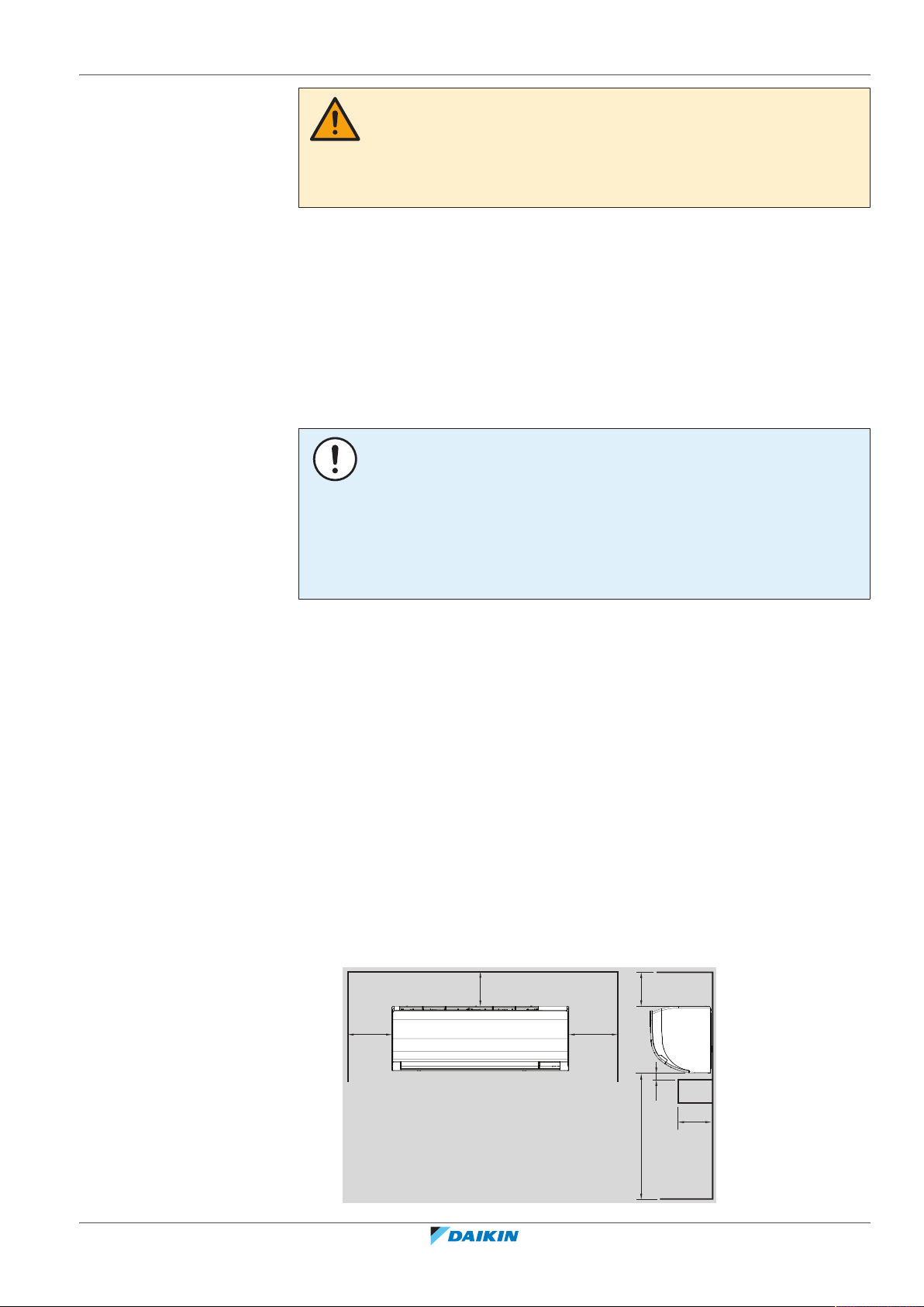
16 | Unit installation
≤120
≥90
≥30
a
b ≥1800
≥50 ≥50
≥90
(mm)
CAUTION
Appliance not accessible to the general public, install it in a secured area, protected
from easy access.
This unit, both indoor and outdoor, is suitable for installation in a commercial and
light industrial environment.
Do NOT install the unit in the following places:
▪ In places where a mineral oil mist, spray or vapour may be present in the
atmosphere. Plastic parts may deteriorate and fall off or cause water leakage.
It is NOT recommended to install the unit in the following places because it may
shorten the life of the unit:
▪ Where the voltage fluctuates a lot
▪ In vehicles or vessels
▪ Where acidic or alkaline vapour is present
NOTICE
The equipment described in this manual may cause electronic noise generated from
radio-frequency energy. The equipment complies to specifications that are designed
to provide reasonable protection against such interference. However, there is no
guarantee that interference will not occur in a particular installation.
It is therefore recommended to install the equipment and electric wires in such a
way that they keep a proper distance from stereo equipment, personal computers,
etc.
▪ In places with weak reception, keep distances of 3 m or more to avoid
electromagnetic disturbance of other equipment and use conduit tubes for
power and transmission lines.
▪ Take care that in the event of a water leak, water cannot cause any damage to
the installation space and surroundings.
▪ Choose a location where the operation noise or the hot/cold air discharged from
the unit will not disturb anyone.
▪ Wall insulation. When conditions in the wall exceed 30°C and a relative humidity
of 80%, or when fresh air is inducted into the wall, then additional insulation is
required (minimum 10mm thickness, polyethylene foam).
▪ Wall strength. Check whether the wall is strong enough to support the weight of
the unit. If there is a risk, reinforce the wall before installing the unit.
▪ Air flow. Make sure nothing blocks the air flow.
▪ Drainage. Make sure condensation water can be evacuated properly.
▪ Spacing. Mind the following requirements:
FAA71+100BUV1B
Split system air conditioner
4P654517-1 – 2021.03
Installer and user reference guide
51
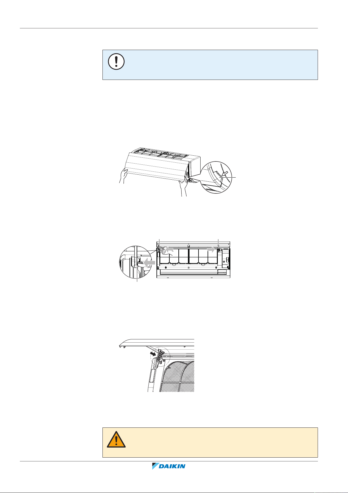
16 | Unit installation
a
a
a
a
16.2 Opening and closing the unit
16.2.1 To remove the front panel
a Obstruction
b Minimum distance to the floor
NOTICE
NEVER mount the indoor unit directly on the wall. Use the attached mounting plate
for installation.
1 Open the front panel. Hold the front panel by the panel tabs on both sides and
open until the panel stops.
a Panel tabs
2 Remove the front panel by pushing hooks on either side of the front panel
towards the side of the unit and remove the panel. Or remove it by sliding the
front panel either to the left or right and pulling it forward.
a Panel hook
16.2.2 To re-install the front panel
1 To attach the front panel, align the hooks of the front panel with the slots and
push them all the way in.
16.2.3 To remove the front grille
Installer and user reference guide
52
2 Close the front panel slowly.
CAUTION
Wear adequate personal protective equipment (protective gloves, safety glasses,…)
when installing, maintaining or servicing the system.
FAA71+100BUV1B
Split system air conditioner
4P654517-1 – 2021.03

16 | Unit installation
3×
6×
3×
aa a
a
a
1 Remove the front panel ("16.2.1To remove the front panel"[452]).
2 Remove the screws (3 for class 71, 6 for class 100) and remove grille clamps
(only for class 100) with the flat screwdriver or a coin.
▪ 3 for class 71:
▪ 6 for class 100:
a Grille clamps
3 Push down the upper hooks marked with a symbol with 3 circles in the
direction of the arrows (3 for class 71, 4 for class 100).
16.2.4 To re-install the front grille
FAA71+100BUV1B
Split system air conditioner
4P654517-1 – 2021.03
a Hook
4 Making sure not to catch the horizontal flaps, remove the front grille by
pulling in the direction of the arrow.
1 Install the front grille and firmly engage the upper hooks (3 for class 71, 4 for
class 100).
2 Install the screws back (3 for class 71, 6 for class 100).
3 For class 100, re-install grille clamps and install the 3 screw covers (accessory).
4 Re-install front panel ("16.2.2To re-install the front panel"[452]).
Installer and user reference guide
53
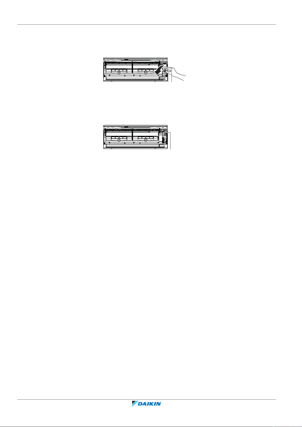
16 | Unit installation
a
b c
a
b
16.2.5 To open the service cover
1 Remove 1 screw from the service cover.
2 Pull out the service cover horizontally away from the unit.
a Service cover screw
b Handle
c Service cover
3 Remove 1 screw from the shield plate.
4 Pull out the shield plate horizontally away from the unit.
a Shield plate
b Screw
16.2.6 To close the service cover
1 Place the shield plate to its original place on the unit.
2 Install 1 screw back on the shield plate.
3 Place the service cover to its original place on the unit.
4 Install 1 screw back on the service cover.
16.3 Mounting the indoor unit
In this chapter
16.3.1 To install the mounting plate................................................................................................................................. 54
16.3.2 To drill a wall hole .................................................................................................................................................. 56
16.3.3 To remove the pipe port cover.............................................................................................................................. 57
16.3.4 To hook the unit on the mounting plate ............................................................................................................... 58
16.3.5 To pass the pipes through the wall hole................................................................................................................ 58
16.3.6 To provide drainage ............................................................................................................................................... 59
16.3.1 To install the mounting plate
1 Remove the mounting plate from the unit.
▪ Remove 2 screws from class 71 or 1 screw from class 100.
Installer and user reference guide
54
▪ Push the knobs in the direction of the arrow.
▪ Remove the mounting plate.
FAA71+100BUV1B
Split system air conditioner
4P654517-1 – 2021.03

16 | Unit installation
A
b
a
b
1
1
c
2
c
2
c
2
3
B
c
2
2
2
2
3
a
b
1
c c
c
a
b
c
d
e
f
A Class 71
B Class 100
a Mounting plate
b Screw
c Knob
2 Choose position for piping (for bottom or side piping see "16.3.3To remove
the pipe port cover"[457]):
a Right piping
b Bottom-right piping
c Back-right piping
d Bottom-left piping
e Back-left piping
f Left piping
3 Attach the mounting plate on the wall and install it temporarily.
4 Level the mounting plate (use tabs on the mounting plate).
5 Mark the centers of the drilling points on the wall using a tape measure.
Position the end of tape measure at symbol " ".
6 Finish the installation by securing the mounting plate on the wall:
▪ When using M4×25L screws (accessory), install evenly at least 4 screws on each
side.
▪ When using bolts (Example: for concrete wall): use M8~M10 bolts (field supply)
one for each side.
INFORMATION
FAA71+100BUV1B
Split system air conditioner
4P654517-1 – 2021.03
The removed pipe port cover can be kept in the mounting plate pocket.
Installer and user reference guide
55
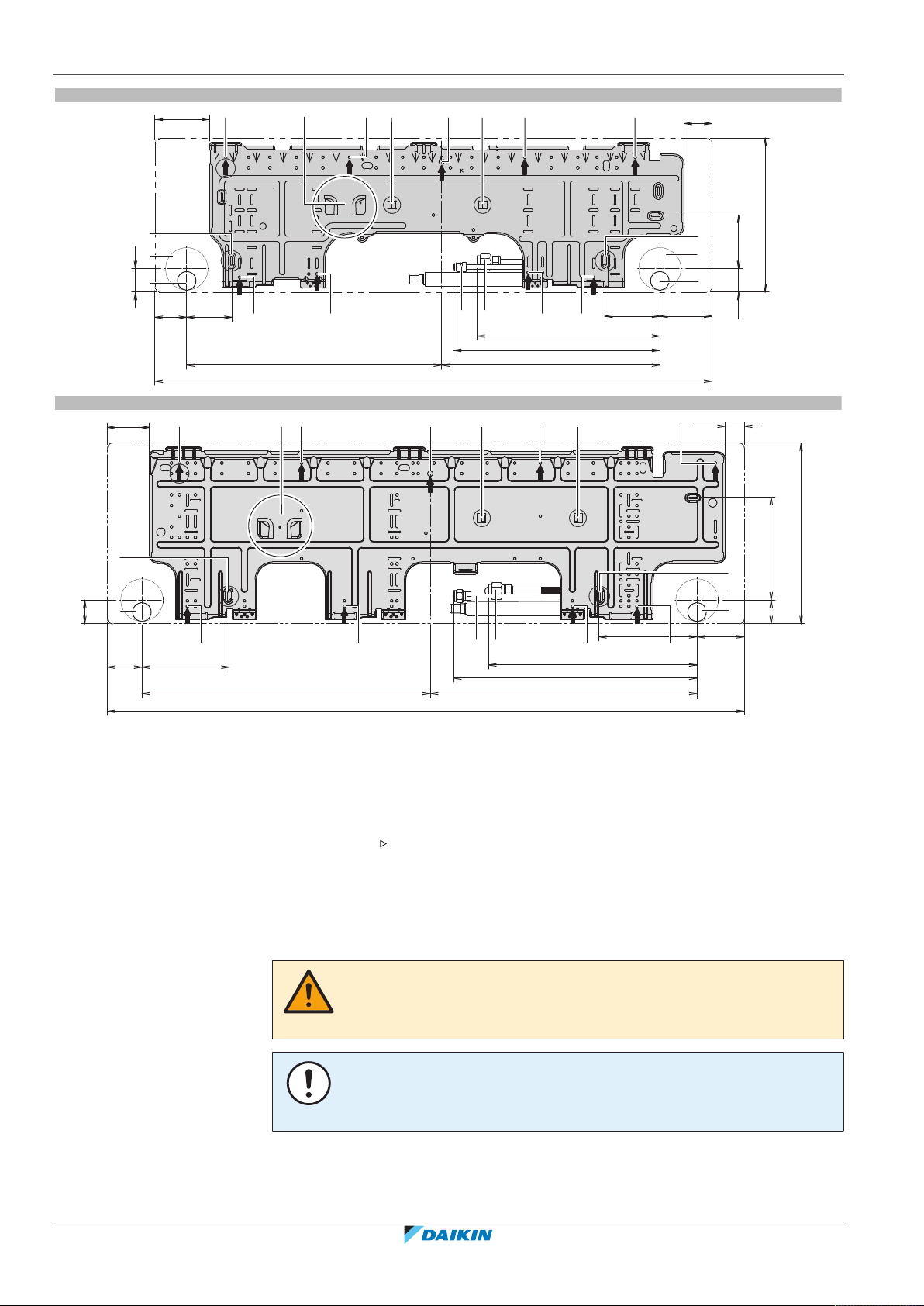
16 | Unit installation
A
(mm)
60 85
480 411
1050
104 98
344
389
44
44
103
52
101
290
d
e
ca a ac
ia
d
e
b
a a a a
f
f
gh
B
(mm)
1200
543 503
16465
186 89
393
459
45
45
80
36
194
340
a a a
a
a a aa
i
b c c
d
e
d
e
f
f
gh
Installer and user reference guide
56
A Pattern for installation with mounting plate for class 71
B Pattern for installation with mounting plate for class 100
a Recommended fixing spots
b Pocket for the pipe port cover
c Tabs for placing a spirit level
d Through-the-wall hole Ø80mm
e Drain hose position
f Position for the tape measure at symbol " "
g Gas pipe end
h Liquid pipe end
i Temporary fixing hole
16.3.2 To drill a wall hole
CAUTION
1 Drill a 80 mm large feed-through hole in the wall with a downward slope
2 Insert a wall embedded pipe into the hole.
For walls containing a metal frame or a metal board, use a wall embedded pipe and
wall cover in the feed-through hole to prevent possible heat, electrical shock, or fire.
NOTICE
Be sure to seal the gaps around the pipes with sealing material (field supply), in order
to prevent water leakage.
towards the outside.
Split system air conditioner
FAA71+100BUV1B
4P654517-1 – 2021.03

3 Insert a wall cover into the wall pipe.
Ø80
a
b
c
a
b
a Wall embedded pipe (field supply)
b Putty (field supply)
c Wall hole cover (field supply)
4 After completing wiring, refrigerant piping and drain piping, do NOT forget to
seal the gap with putty.
16.3.3 To remove the pipe port cover
INFORMATION
To connect the piping on right-side, right-bottom, left-side or left-bottom, the pipe
port cover MUST be removed.
16 | Unit installation
a Cut off for side piping
b Cut off for bottom piping
1 Remove the front grille ("16.2.3To remove the front grille"[452]).
2 Cut off the pipe port cover from inside the front grille using a coping saw.
3 Remove any burrs along the cut section using a half round needle file.
NOTICE
Do NOT use nippers to remove the pipe port cover, as this would damage the front
grille.
FAA71+100BUV1B
Split system air conditioner
4P654517-1 – 2021.03
Installer and user reference guide
57

16 | Unit installation
a
c
db e
c
e f
bda
A
A
c g
16.3.4 To hook the unit on the mounting plate
1 Remove the front panel ("16.2.1To remove the front panel"[452]).
2 Set the indoor unit on the mounting plate hooks. Use the " " marks as a
guide.
3 Place piece of packing material for support.
a Front grille
b Refrigerant piping
c Tab 2×
d Mounting plate (accessory)
e Piece of packing material
16.3.5 To pass the pipes through the wall hole
1 Connect the drain piping "16.3.6To provide drainage"[459], the refrigerant
piping "17Piping installation" [4 62] and the electrical wiring "18 Electrical
installation"[467].
2 Shape the refrigerant pipes along the pipe path marking on the mounting
plate.
3 Fix the electrical wiring and the refrigerant pipes together using vinyl tape
(field supply).
a Drain hose
b Wall hole
c Refrigerant piping
d Electrical wiring
e Vinyl tape (field supply)
f Power supply wiring
g Transmission wiring and user interface wiring
Installer and user reference guide
58
NOTICE
▪ Do NOT bend refrigerant pipes.
▪ Do NOT push the refrigerant pipes onto the bottom frame or the front grille.
FAA71+100BUV1B
Split system air conditioner
4P654517-1 – 2021.03

4 Pass the drain hose and refrigerant pipes through the wall hole.
360
Ø18
(mm)
5 When the complete installation is finished (drain piping "16.3.6 To provide
16.3.6 To provide drainage
Make sure condensation water can be evacuated properly. This involves:
16 | Unit installation
drainage" [4 59], the refrigerant piping "17 Piping installation" [4 62] and
the electrical wiring "18 Electrical installation" [4 67]), fix the indoor unit on
the mounting plate "19.1To fix the unit on the mounting plate"[473].
▪ General guidelines
▪ Connecting the drain piping to the indoor unit
▪ Checking for water leaks
General guidelines
▪ Pipe length. Keep drain piping as short as possible.
▪ Pipe size. Keep the pipe size equal to or greater than that of the connecting pipe
(vinyl pipe with nominal Ø13 mm).
NOTICE
▪ Install the drain hose with a downward slope.
▪ Traps are NOT permitted.
▪ Do NOT put the end of the hose in water.
FAA71+100BUV1B
Split system air conditioner
4P654517-1 – 2021.03
▪ Drain hose extension. When extending the drain hose, use a field supplied
extension hose with nominal Ø13 mm. Do NOT forget to use a heat insulation
tube on the indoor section of the extension hose.
Installer and user reference guide
59
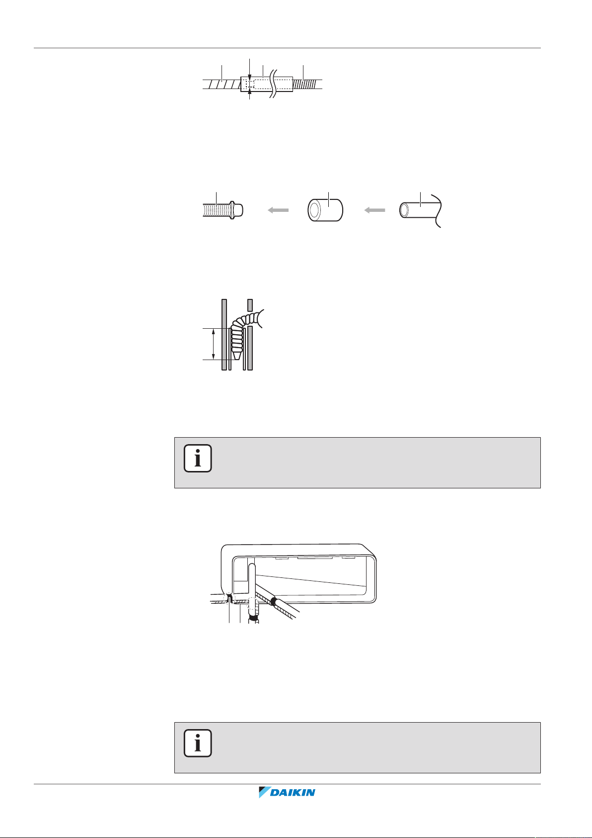
16 | Unit installation
a
b c
Ø18
a b c
≥50
mm
A
B
C
a
b
a Drain hose supplied with the indoor unit
b Heat insulation tube (field supply)
c Extension drain hose (field supply)
▪ Rigid polyvinyl chloride pipe. When connecting a rigid polyvinyl chloride pipe
(nominal Ø13mm) directly to the drain hose as with embedded piping work, use
a field supplied drain socket (nominal Ø13mm).
a Drain hose supplied with the indoor unit
b Drain socket with nominal Ø13mm (field supply)
c Rigid polyvinyl chloride pipe (field supply)
▪ Insert the drain hose in the drain pipe as shown in the following figure, so it will
NOT be pulled out of the drain pipe.
▪ Condensation. Take measures against condensation. Insulate the complete drain
piping in the building.
To connect the piping on right side, right-back, or right-bottom
INFORMATION
The factory default is right-side piping. For left-side piping, remove the piping from
the right side and install it on the left side.
1 Attach the drain hose with adhesive vinyl tape to the bottom of the
refrigerant pipes.
2 Wrap the drain hose and the refrigerant pipes together using insulation tape.
A Right-side piping
B Right-bottom piping
C Right-back piping
a Remove the pipe port cover here for right side piping
b Remove the pipe port cover here for right-bottom piping
To connect the piping on left side, left-back, or left-bottom
Installer and user reference guide
60
INFORMATION
The factory default is right-side piping. For left-side piping, remove the piping from
the right side and install it on the left side.
FAA71+100BUV1B
Split system air conditioner
4P654517-1 – 2021.03
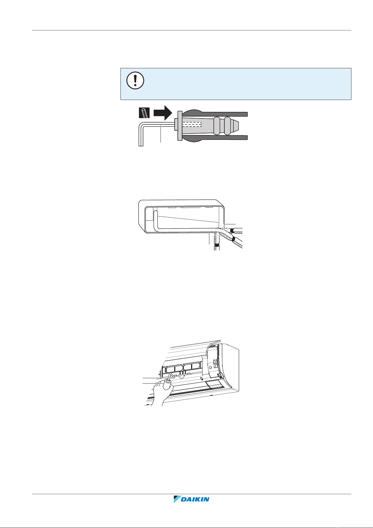
16 | Unit installation
a
A
B
C
b
a
a
b
1 Remove the insulation fixing screw on the right side and remove the drain
hose.
2 Remove the drain plug on the left side and attach it to the right side.
NOTICE
Do NOT apply lubricating oil (refrigerant oil) to the drain plug when inserting it. The
drain plug may deteriorate and cause drain leakage from the plug.
a 4mm hexagonal wrench
3 Insert the drain hose on the left side and do not forget to tighten it with the
fixing screw; otherwise water leakage may occur.
4 Attach the drain hose to the refrigerant piping bottom side using adhesive
vinyl tape.
To check for water leaks
1 Remove the air filters (see "10.2.3To clean the air filter"[436]).
2 Gradually pour approximately 1 l of water in the drain pan, and check for
water leaks.
3 Reattach the air filters (see "10.2.3To clean the air filter"[436]).
A Left-side piping
B Left-back piping
C Left-bottom piping
a Remove the pipe port cover here for left-side piping
b Remove the pipe port cover here for left-bottom piping
a Drain pan
b Plastic container
FAA71+100BUV1B
Split system air conditioner
4P654517-1 – 2021.03
Installer and user reference guide
61

17 | Piping installation
t
Ø
17 Piping installation
In this chapter
17.1 Preparing refrigerant piping
17.1.1 Refrigerant piping requirements
17.1 Preparing refrigerant piping ................................................................................................................................................... 62
17.1.1 Refrigerant piping requirements ........................................................................................................................... 62
17.1.2 Refrigerant piping insulation.................................................................................................................................. 63
17.2 Connecting the refrigerant piping .......................................................................................................................................... 63
17.2.1 About connecting the refrigerant piping............................................................................................................... 63
17.2.2 Precautions when connecting the refrigerant piping............................................................................................ 63
17.2.3 Guidelines when connecting the refrigerant piping.............................................................................................. 64
17.2.4 Pipe bending guidelines......................................................................................................................................... 65
17.2.5 To flare the pipe end.............................................................................................................................................. 65
17.2.6 To connect the refrigerant piping to the indoor unit............................................................................................ 66
INFORMATION
Also read the precautions and requirements in the "2 General safety
precautions"[48].
▪ Foreign materials inside pipes (including oils for fabrication) must be
≤30mg/10m.
Refrigerant piping diameter
For piping connections of the indoor unit use the following piping diameters:
Refrigerant piping material
▪ Piping material: Phosphoric acid deoxidised seamless copper.
CAUTION
Piping MUST be installed according to instructions given in "17 Piping
installation" [4 62]. Only mechanical joints (e.g. braze+flare connections) that are
compliant with the latest version of ISO14903 can be used.
NOTICE
The piping and other pressure-containing parts shall be suitable for refrigerant. Use
phosphoric acid deoxidised seamless copper for refrigerant.
Pipe outer diameter (mm)
Liquid pipe Gas pipe
Ø9.5 Ø15.9
▪ Flare connections: Only use annealed material.
▪ Piping temper grade and thickness:
Outer diameter (Ø) Temper grade Thickness (t)
(a)
9.5mm (3/8") Annealed (O) ≥0.8mm
15.9mm (5/8") Annealed (O)
(a)
Depending on the applicable legislation and the maximum working pressure of the unit
(see "PS High" on the unit name plate), larger piping thickness might be required.
Installer and user reference guide
62
FAA71+100BUV1B
Split system air conditioner
4P654517-1 – 2021.03

17.1.2 Refrigerant piping insulation
ØiØ
i
t
ØpØ
p
▪ Use polyethylene foam as insulation material:
- with a heat transfer rate between 0.041 and 0.052 W/mK (0.035 and
0.045kcal/mh°C)
- with a heat resistance of at least 120°C
▪ Insulation thickness
17 | Piping installation
Pipe outer diameter (Øp) Insulation inner diameter
9.5mm (3/8") 12~15mm ≥13mm
15.9mm (5/8") 17~20mm ≥13mm
If the temperature is higher than 30°C and the humidity is higher than RH80%, the
thickness of the insulation materials should be at least 20 mm to prevent
condensation on the surface of the insulation.
17.2 Connecting the refrigerant piping
17.2.1 About connecting the refrigerant piping
Before connecting the refrigerant piping
Make sure the outdoor and indoor unit are mounted.
Typical workflow
Insulation thickness (t)
(Øi)
Connecting the refrigerant piping involves:
▪ Connecting the refrigerant piping to the indoor unit
▪ Connecting the refrigerant piping to the outdoor unit
▪ Insulating the refrigerant piping
▪ Keeping in mind the guidelines for:
- Pipe bending
- Flaring pipe ends
- Using the stop valves
17.2.2 Precautions when connecting the refrigerant piping
INFORMATION
Also read the precautions and requirements in the following chapters:
▪ "2General safety precautions"[48]
▪ "17.1Preparing refrigerant piping"[462]
DANGER: RISK OF BURNING/SCALDING
FAA71+100BUV1B
Split system air conditioner
4P654517-1 – 2021.03
Installer and user reference guide
63

17 | Piping installation
CAUTION
▪ Do NOT use mineral oil on flared part.
▪ Do NOT reuse piping from previous installations.
▪ NEVER install a drier to this unit to guarantee its lifetime. The drying material may
dissolve and damage the system.
NOTICE
Take the following precautions on refrigerant piping into account:
▪ Avoid anything but the designated refrigerant to get mixed into the refrigerant
cycle (e.g. air).
▪ Only use R32 or R410A when adding refrigerant. Refer to the outdoor unit
specifications for the type of refrigerant to be used.
▪ Only use installation tools (e.g. manifold gauge set) that are exclusively used for
R32 or R410A installations to withstand the pressure and to prevent foreign
materials (e.g. mineral oils and moisture) from mixing into the system.
▪ Install the piping so that the flare is NOT subjected to mechanical stress.
▪ Protect the piping as described in the following table to prevent dirt, liquid or
dust from entering the piping.
▪ Use caution when passing copper tubes through walls (see figure below).
Unit Installation period Protection method
Outdoor unit >1month Pinch the pipe
<1month Pinch or tape the pipe
Indoor unit Regardless of the period
INFORMATION
Do NOT open the refrigerant stop valve before checking the refrigerant piping. When
you need to charge additional refrigerant it is recommended to open the refrigerant
stop valve after charging.
17.2.3 Guidelines when connecting the refrigerant piping
Take the following guidelines into account when connecting pipes:
▪ Coat the flare inner surface with ether oil or ester oil when connecting a flare
nut. Tighten 3 or 4 turns by hand, before tightening firmly.
▪ ALWAYS use 2 wrenches together when loosening a flare nut.
Installer and user reference guide
64
▪ ALWAYS use a spanner and torque wrench together to tighten the flare nut when
connecting the piping. This to prevent nut cracking and leaks.
FAA71+100BUV1B
Split system air conditioner
4P654517-1 – 2021.03

a
b
c
d
Piping size (mm) Tightening torque
R=
0.4~0.8
±2
45°
90°
±2
ØA
a b
A
Ø15.9 62~75 19.3~19.7
17.2.4 Pipe bending guidelines
Use a pipe bender for bending. All pipe bends should be as gentle as possible
(bending radius should be 30~40 mm or larger).
17 | Piping installation
a Torque wrench
b Spanner
c Piping union
d Flare nut
Flare dimensions
(N•m)
Ø9.5 33~39 12.8~13.2
(A) (mm)
Flare shape (mm)
17.2.5 To flare the pipe end
1 Cut the pipe end with a pipe cutter.
2 Remove burrs with the cut surface facing down so that the chips do NOT enter
the pipe.
3 Remove the flare nut from the stop valve and put the flare nut on the pipe.
4 Flare the pipe. Set exactly at the position as shown in the following figure.
CAUTION
▪ Incomplete flaring may cause refrigerant gas leakage.
▪ Do NOT re-use flares. Use new flares to prevent refrigerant gas leakage.
▪ Use flare nuts that are included with the unit. Using different flare nuts may
cause refrigerant gas leakage.
a Cut exactly at right angles.
b Remove burrs.
FAA71+100BUV1B
Split system air conditioner
4P654517-1 – 2021.03
Flare tool for R410A or
R32 (clutch type)
(Ridgid-type)
Conventional flare tool
Clutch type
Wing nut type
(Imperial-type)
A 0~0.5mm 1.0~1.5mm 1.5~2.0mm
5 Check that the flaring is properly made.
Installer and user reference guide
65

17 | Piping installation
a b
c
d
f
b
e
g
a c
h
db
i
17.2.6 To connect the refrigerant piping to the indoor unit
a Flare’s inner surface MUST be flawless.
b The pipe end MUST be evenly flared in a perfect circle.
c Make sure the flare nut is fitted.
CAUTION
Install the refrigerant piping or components in a position where they are unlikely to
be exposed to any substance which may corrode components containing refrigerant,
unless the components are constructed of materials that are inherently resistant to
corrosion or are suitably protected against corrosion.
WARNING: MILDLY FLAMMABLE MATERIAL
The R32 refrigerant (if applicable) in this unit is mildly flammable. Refer to the
outdoor unit specifications for the type of refrigerant to be used.
▪ Pipe length. Keep refrigerant piping as short as possible.
1 Flare connections. Connect refrigerant piping to the unit using flare
connections.
2 Insulation. Insulate the refrigerant piping, the insulating tape should be
wrapped from the L-shaped bend all the way to the end inside the unit as
follows:
a Field piping
b Indoor unit piping insulation tubing
c Indoor unit piping
d Insulating tubing tape
e Insulating tape (accessory)
f Large tie wrap (accessory)
g Beginning of wrapping
h L-shaped bend
i Insulation tubing seam (make sure there are no gaps in the insulation tubing seam)
NOTICE
Make sure to insulate all refrigerant piping. Any exposed piping might cause
condensation.
Installer and user reference guide
66
FAA71+100BUV1B
Split system air conditioner
4P654517-1 – 2021.03
18 Electrical installation
In this chapter
18.1 About connecting the electrical wiring .................................................................................................................................. 67
18.1.1 Precautions when connecting the electrical wiring .............................................................................................. 67
18.1.2 Guidelines when connecting the electrical wiring ................................................................................................ 68
18.1.3 Specifications of standard wiring components ..................................................................................................... 69
18.2 To connect the electrical wiring to the indoor unit ............................................................................................................... 69
18.1 About connecting the electrical wiring
Typical workflow
Connecting the electrical wiring typically consists of the following stages:
1 Making sure the power supply system complies with the electrical
specifications of the units.
2 Connecting the electrical wiring to the outdoor unit.
3 Connecting the electrical wiring to the indoor unit.
4 Connecting the main power supply.
18 | Electrical installation
18.1.1 Precautions when connecting the electrical wiring
DANGER: RISK OF ELECTROCUTION
WARNING
ALWAYS use multicore cable for power supply cables.
INFORMATION
Also read the precautions and requirements in the "2 General safety
precautions"[48].
INFORMATION
Also read "18.1.3Specifications of standard wiring components"[469].
WARNING
▪ All wiring MUST be performed by an authorised electrician and MUST comply
with the applicable legislation.
▪ Make electrical connections to the fixed wiring.
▪ All components procured on-site and all electrical construction MUST comply
with the applicable legislation.
FAA71+100BUV1B
Split system air conditioner
4P654517-1 – 2021.03
Installer and user reference guide
67
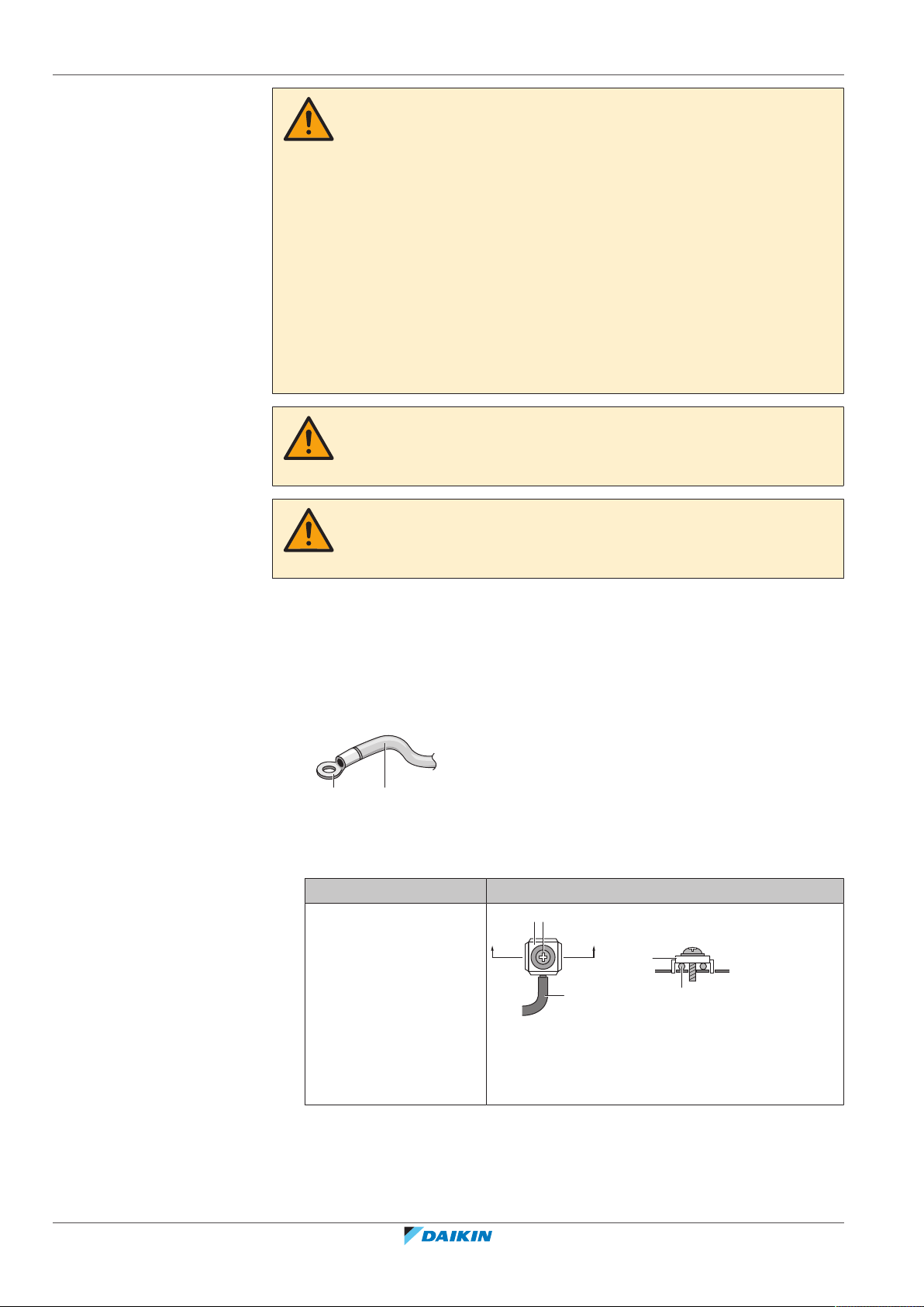
18 | Electrical installation
b a
c b
c
aa
A
AA´
A´
WARNING
▪ If the power supply has a missing or wrong N-phase, equipment might break
down.
▪ Establish proper earthing. Do NOT earth the unit to a utility pipe, surge absorber,
or telephone earth. Incomplete earthing may cause electrical shock.
▪ Install the required fuses or circuit breakers.
▪ Secure the electrical wiring with cable ties so that the cables do NOT come in
contact with sharp edges or piping, particularly on the high-pressure side.
▪ Do NOT use taped wires, stranded conductor wires, extension cords, or
connections from a star system. They can cause overheating, electrical shock or
fire.
▪ Do NOT install a phase advancing capacitor, because this unit is equipped with an
inverter. A phase advancing capacitor will reduce performance and may cause
accidents.
WARNING
Use an all-pole disconnection type breaker with at least 3mm between the contact
point gaps that provide full disconnection under overvoltage category III.
WARNING
If the supply cord is damaged, it MUST be replaced by the manufacturer, its service
agent or similarly qualified persons in order to avoid a hazard.
18.1.2 Guidelines when connecting the electrical wiring
Keep the following in mind:
▪ If stranded conductor wires are used, install a round crimp-style terminal on the
end of the wire. Place the round crimp-style terminal on the wire up to the
covered part and fasten the terminal with the appropriate tool.
a Stranded conductor wire
b Round crimp-style terminal
▪ Use the following methods for installing wires:
Wire type Installation method
Single-core wire
Installer and user reference guide
68
a Curled single-core wire
b Screw
c Flat washer
FAA71+100BUV1B
Split system air conditioner
4P654517-1 – 2021.03

Wire type Installation method
c b ba c
a
B
B
1-3
Stranded conductor wire
with round crimp-style
terminal
Tightening torques
Wiring Screw size Tightening torque
18 | Electrical installation
a Terminal
b Screw
c Flat washer
Allowed
NOT allowed
(N•m)
Interconnection cable
(indoor↔outdoor)
User interface cable M3.5 0.79~0.97
▪ The earth wire between the wire retainer and the terminal must be longer than
the other wires.
18.1.3 Specifications of standard wiring components
Component Specification
Interconnection cable (indoor↔outdoor) 4-core cable 1.5mm2~2.5mm2 and
User interface cable Vinyl cords with 0.75 to 1.25mm²
(a)
In case the conduit pipes are not used, use H07RN-F (60245 IEC 66).
M4 1.18~1.44
applicable for 220~240V
H05RN-F (60245 IEC 57)
sheath or cables (2‑core wires)
H03VV-F (60227 IEC 52)
Maximum 500m
(a)
18.2 To connect the electrical wiring to the indoor unit
FAA71+100BUV1B
Split system air conditioner
4P654517-1 – 2021.03
NOTICE
▪ Follow the wiring diagram (delivered with the unit, located at the inside of the
service cover).
▪ For instructions on how to connect the optional equipment, see the installation
manual delivered with the optional equipment.
▪ Make sure the electrical wiring does NOT obstruct proper reattachment of the
service cover.
Installer and user reference guide
69

18 | Electrical installation
1
3
2
P
1
REMOTE
CNTRL
TRANSMISSION
WIRING
FORCED
OFF
T
2
P2F1F2T
1
1
3
2
e
70~90
10~20
R-Ctrl D III-Net
F1 F2 T1 T2P1 P2
70~90
7
b
c
d
a
a
It is important to keep the power supply and the transmission wiring separated
from each other. In order to avoid any electrical interference the distance between
both wirings should ALWAYS be at least 50mm.
NOTICE
Be sure to keep the power line and transmission line apart from each other.
Transmission wiring and power supply wiring may cross, but may NOT run parallel.
1 Remove the service cover and shield plate (see "16.2.5 To open the service
cover"[454]).
2 User interface cable: Connect the cable to the terminal block (symbols P1,
P2).
3 Interconnection cable (indoor↔outdoor): Route the cable through the
frame, connect the cable to the terminal block (make sure the numbers match
with the numbers on the outdoor unit, and connect the earth wire), and fix
the cable with a cable tie.
4 Seal all gaps with a sealing material (field supply) to prevent small animals
from entering the system.
5 Reattach the shield plate and the service cover (see "16.2.6 To close the
service cover"[454]).
a Interconnection wiring terminal
b User interface wiring terminal
c Interconnection wiring cable
d User interface terminal wiring cable
e Small tie wrap (accessory)
Electrical wiring route:
a Electrical wiring
Complete system wiring example
For the wiring of outdoor units, refer to the installation manual attached to the
outdoor units.
Pair type: 1 remote controller controls 1 indoor unit (standard)
Installer and user reference guide
70
FAA71+100BUV1B
Split system air conditioner
4P654517-1 – 2021.03
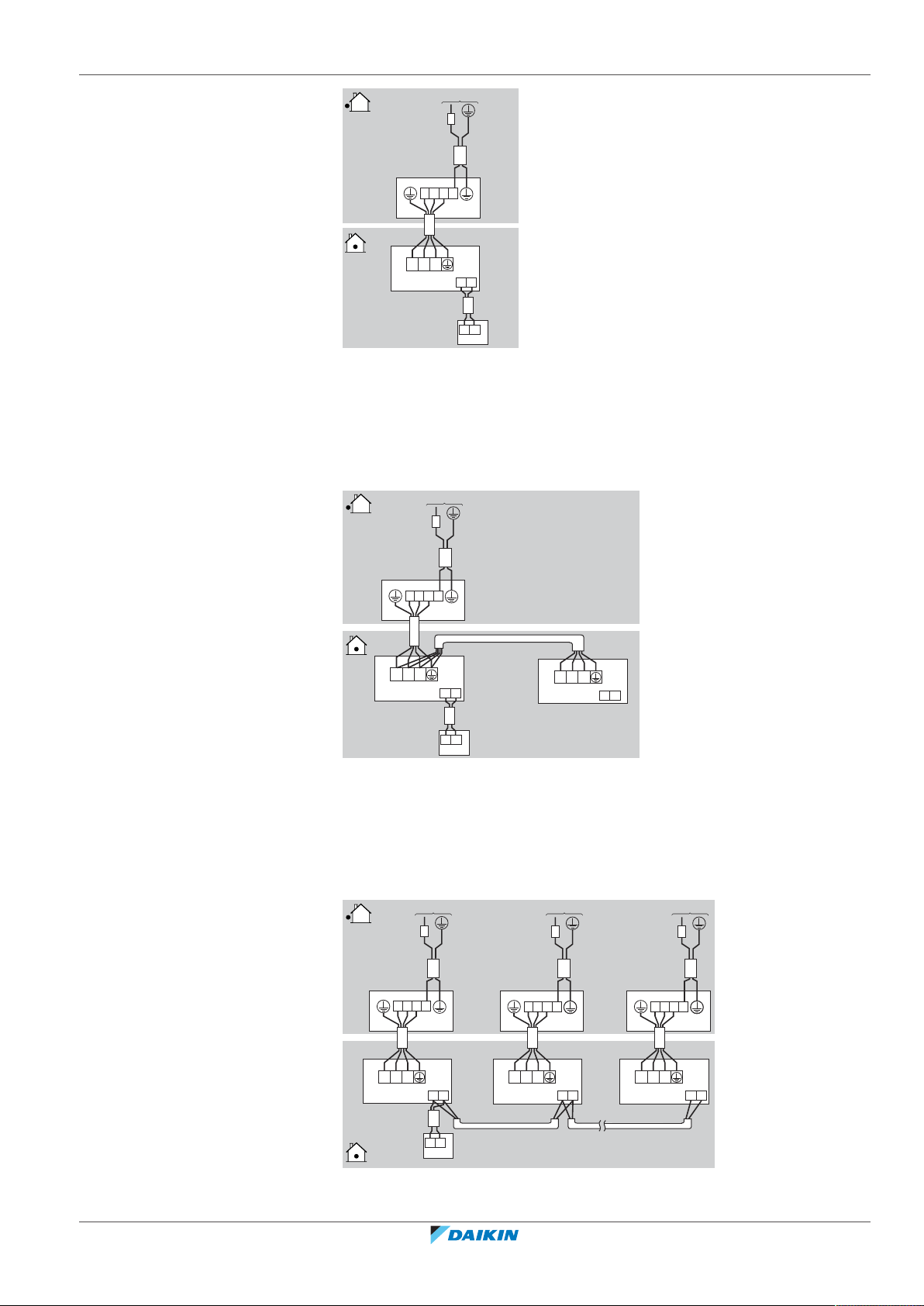
18 | Electrical installation
P1 P2
21 3
P1 P2
21 3
e
b
c
d
a
21 3
P1 P2
P1 P2
P1 P2
21 3
1 2 3
e
c
d1 d2
b
a
P1 P2
1 2 3
21 3 1 2 3
P1 P2 P1 P2 P1 P2
21 3 21 3 1 2 3
e
c c c
d1 d2 d2
b b b
a a a
a Power supply
b Residual current device
c Outdoor unit
d Indoor unit
e User interface
Simultaneous operation system: 1 user interface controls 2 indoor units (2
indoor units operates equally)
FAA71+100BUV1B
Split system air conditioner
4P654517-1 – 2021.03
a Power supply
b Residual current device
c Outdoor unit
d Indoor unit
e User interface
Group control: 1 remote controller controls up to 4 indoor units (all indoor units
operate according to the user interface)
a Power supply
b Residual current device
Installer and user reference guide
71
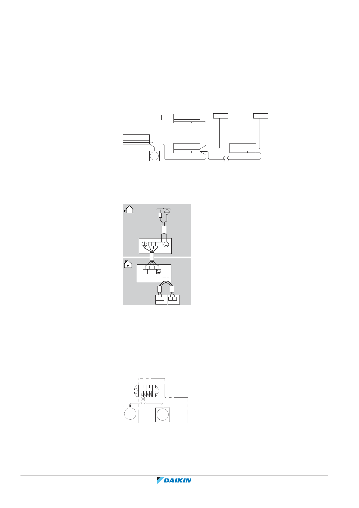
18 | Electrical installation
b(1)
b(2)
b(16)
d
a(1)
c
a(2)
a(16)
21 3
P1 P2
21 3
e(1) e(2)
b
c
d
a
P2 P1 P2P1
P1 P2 F1 F2
b
a
c
c Outdoor unit
d1 Indoor unit (master)
d2 Indoor unit (slave)
e User interface
▪ When using a pair type system as a master system for simultaneous multiple unit
operation, you may carry out simultaneous start/stop (group) control up to 16
units with 1 remote controller. (All indoor units operate according to the user
interface)
▪ The thermistor reading of room temperature is effective only for the indoor unit
connected to the user interface.
a Outdoor unit (number)
b Indoor unit (number)
c Slave indoor unit
d User interface
2 remote controllers control: 2 remote controllers control 1 indoor unit.
Installer and user reference guide
72
a Power supply
b Residual current device
c Outdoor unit
d Indoor unit
e User interface
1 Remove the service cover.
2 Lay crossover between the terminals (P1, P2) inside the control box for the
remote controller (there is no polarity). For simultaneous operation system,
be sure to connect the user interface to the master unit.
a Terminal block (X1M) (Master unit)
b User interface (MAIN)
c User interface (SUB)
3 When using 2 user interfaces, one must be set to “MAIN” and the other to
“SUB”. For setting refer to the installation manual of the connected user
interface.
Split system air conditioner
4P654517-1 – 2021.03
FAA71+100BUV1B

19 | Finishing the indoor unit installation
a
b
e
c
d
19 Finishing the indoor unit installation
19.1 To fix the unit on the mounting plate
1 Remove the piece of packing material.
2 Press the bottom frame of the unit with both hands to set it on the bottom
hooks of the mounting plate. Make sure that the wires do NOT get squeezed
or caught anywhere.
3 Press the bottom edge of the indoor unit with both hands until it is firmly
caught by the mounting plate hooks.
4 Secure the indoor unit to the mounting plate using indoor unit fixing screws
M4×12L (2 for class 71, 3 for class 100) (accessory).
a Mounting plate (accessory)
b Refrigerant piping
c Insulation tape
d Bottom frame
e Screw M4×12L ( accessory) 2 for class 71, 3 for class 100
5 Re-install the front grille and front panel.
FAA71+100BUV1B
Split system air conditioner
4P654517-1 – 2021.03
Installer and user reference guide
73

20 | Commissioning
20 Commissioning
In this chapter
20.1 Overview: Commissioning
NOTICE
General commissioning checklist. Next to the commissioning instructions in this
chapter, a general commissioning checklist is also available on the Daikin Business
Portal (authentication required).
The general commissioning checklist is complementary to the instructions in this
chapter and can be used as a guideline and reporting template during the
commissioning and hand-over to the user.
20.1 Overview: Commissioning ...................................................................................................................................................... 74
20.2 Precautions when commissioning.......................................................................................................................................... 74
20.3 Checklist before commissioning............................................................................................................................................. 74
20.4 To perform a test run ............................................................................................................................................................. 75
This chapter describes what you have to do and know to commission the system
after it is installed.
Typical workflow
Commissioning typically consists of the following stages:
1 Checking the "Checklist before commissioning".
2 Performing a test run for the system.
20.2 Precautions when commissioning
INFORMATION
During the first running period of the unit, the required power may be higher than
stated on the nameplate of the unit. This phenomenon is caused by the compressor,
that needs a continuous run time of 50hours before reaching smooth operation and
stable power consumption.
NOTICE
ALWAYS operate the unit with thermistors and/or pressure sensors/switches. If NOT,
burning of the compressor might be the result.
20.3 Checklist before commissioning
Installer and user reference guide
74
After the installation of the unit, first check the items listed below. Once all checks
are fulfilled, the unit must be closed. Power-up the unit after it is closed.
You read the complete installation and operation instructions, as described in the installer
and user reference guide.
The indoor unit is properly mounted.
The outdoor unit is properly mounted.
FAA71+100BUV1B
Split system air conditioner
4P654517-1 – 2021.03

20 | Commissioning
Make sure drain piping is properly installed, insulated and drainage flows smoothly. Check
for water leaks.
Possible consequence: Condensate water might drip.
The refrigerant pipes (gas and liquid) are installed correctly and thermally insulated.
There are NO refrigerant leaks.
There are NO missing phases or reversed phases.
The system is properly earthed and the earth terminals are tightened.
The fuses or locally installed protection devices are installed according to this document,
and have NOT been bypassed.
The power supply voltage matches the voltage on the identification label of the unit.
There are NO loose connections or damaged electrical components in the switchbox.
There are NO damaged components or squeezed pipes on the inside of the indoor and
outdoor units.
The stop valves (gas and liquid) on the outdoor unit are fully open.
20.4 To perform a test run
INFORMATION
For the test run procedure, see the reference guide or the service manual of the
used user interface.
NOTICE
Do NOT interrupt the test run.
FAA71+100BUV1B
Split system air conditioner
4P654517-1 – 2021.03
Installer and user reference guide
75
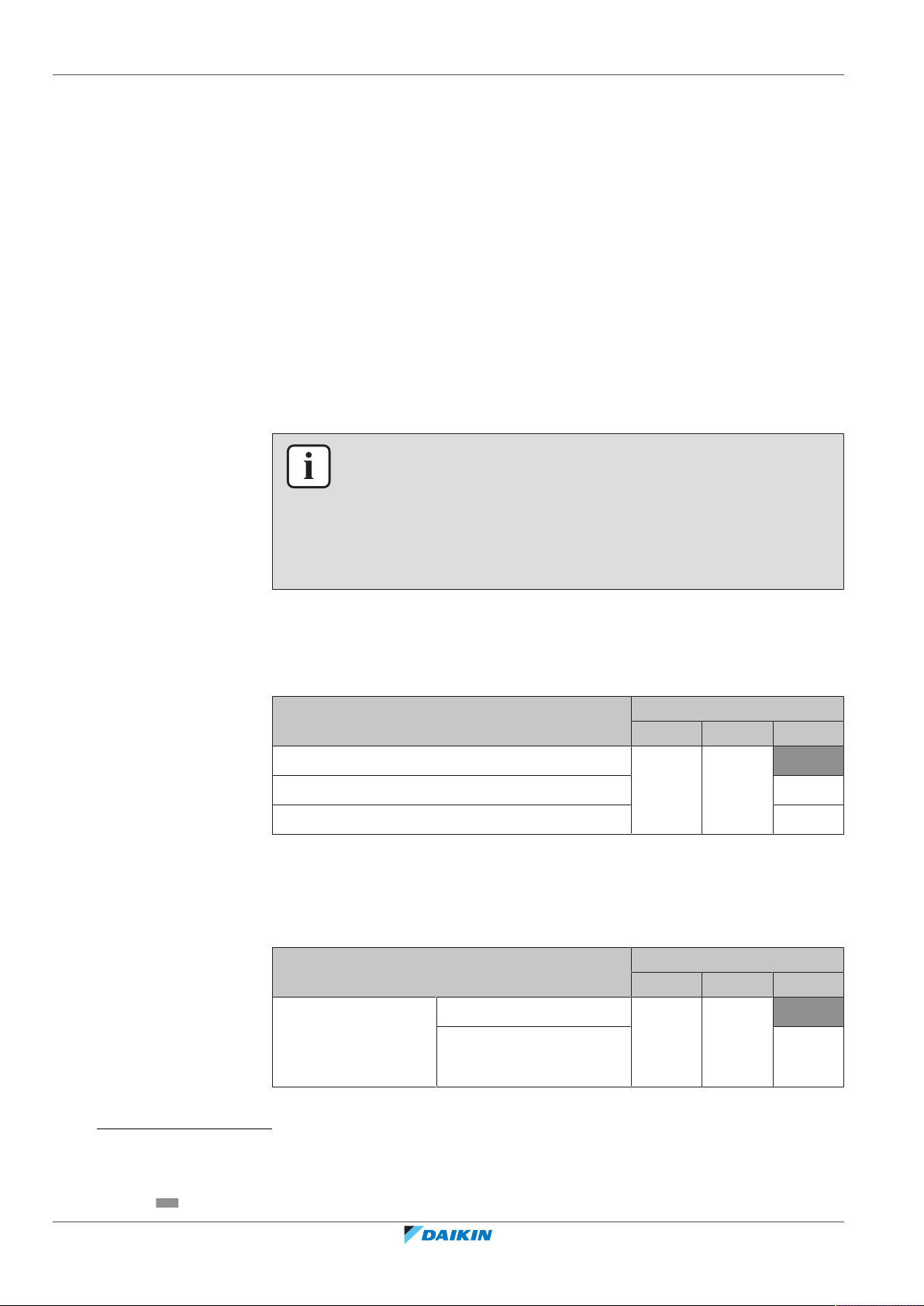
21 | Configuration
21 Configuration
21.1 Field setting
Make the following field settings so that they correspond with the actual
installation setup and with the needs of the user:
▪ Airflow rate increase mode
▪ Airflow rate when thermostat control is OFF
▪ Time to clean air filter
▪ Indoor unit number of simultaneous operation system
▪ Simultaneous operation system individual setting
▪ Computerised control (forced OFF and ON/OFF operation)
INFORMATION
▪ The connection of optional accessories to the indoor unit might cause changes to
some field settings. For more information, see the installation manual of the
optional accessory.
▪ Following setting are only applicable when using the BRC1H52* user interface.
When using any other user interface, see the installation manual or service
manual of the user interface.
Setting: Airflow rate increase mode
This setting must correspond with the needs of the user. It is possible to raise set
airflow (HIGH, MEDIUM and LOW) from the field. Change the value number (—) as
shown in the table below.
If you want airflow… Then
(1)
M SW —
Standard 13 (23) 0 01
A little increased 02
Increased 03
Setting: Airflow rate when thermostat control is OFF
This setting must correspond with the needs of the user. It determines the fan
speed of the indoor unit during thermostat OFF condition.
1 If you have set the fan to operate, set the airflow rate speed:
If you want… Then
(1)
M SW —
Fan operation during
thermostat OFF
(cooling/heating
Normal 11 (21) 2 01
Stop 02
operation)
(1)
Field settings are defined as follows:
• M: Mode number – First number: for group of units – Number between brackets: for individual unit
• SW: Setting number
• —: Value number
• : Default
Installer and user reference guide
76
FAA71+100BUV1B
Split system air conditioner
4P654517-1 – 2021.03
21 | Configuration
If you want… Then
(1)
M SW —
During thermostat
OFF at cooling
operation
(2)
LL
Setup volume
12 (22) 6 01
(2)
02
OFF 03
(2)
(2)
04
05
12 (22) 3 01
(2)
02
During thermostat
OFF at heating
operation
Monitoring 1
Monitoring 3
(2)
LL
Setup volume
OFF 03
Monitoring 1
Monitoring 2
(2)
(2)
04
05
Setting: Time to clean air filter
This setting must correspond with the air contamination in the room. It determines
the interval at which "Time to clean filter" notification is displayed on the user
interface.
If you want an interval of…
(air contamination)
M SW —
Then
(1)
±200h (light) 10 (20) 0 01
±100h (heavy) 02
Setting: Indoor unit number of simultaneous operation system
For simultaneous operation system mode made following field setting:
If the system mode is… Then
(1)
M SW —
Pair (1 unit) 11 (21) 0 01
Simultaneous (2 units) 02
Simultaneous (3 units) 03
When using in simultaneous operation system mode, refer to “simultaneous
operation system individual setting” section to set master and slave units
separately.
When using wireless remote controllers, wireless remote controller address
setting is necessary. Refer to the installation manual attached to the wireless
remote controller for setting instructions.
(1)
Field settings are defined as follows:
• M: Mode number – First number: for group of units – Number between brackets: for individual unit
• SW: Setting number
• —: Value number
• : Default
(2)
Fan speed:
• LL: Low fan speed (set during thermostat OFF)
• L: Low fan speed (set by the user interface)
• Setup volume: The fan speed corresponds to the speed the user has set using the fan speed button on the user interface.
• Monitoring 1, 2, 3: The fan is OFF, but runs for a short time every 6minutes to detect the room temperature by LL (Monitoring 1), L
(Monitoring 2) or Setup volume (Monitoring 3).
FAA71+100BUV1B
Split system air conditioner
4P654517-1 – 2021.03
Installer and user reference guide
77
21 | Configuration
F2 T1 T2
FORCED
OFF
a
Setting: Simultaneous operation system individual setting
Perform the following procedure when setting the master and slave unit
separately.
1 Change setting:
If you want… Then
(1)
M SW —
Unified setting 11 (21) 1 01
Individual setting 02
2 Perform field setting for the master unit.
3 Turn off main power supply.
4 Detach user interface from the master unit and connect it to the slave unit.
Turn on the main power supply switch and set individual setting.
5 Perform field setting for slave unit.
6 Turn off the main power supply.
7 If there is more than one slave unit, repeat setting for each
8 Detach user interface from the slave unit, and reattach to the master unit.
INFORMATION
▪ You do not need to rewire the user interface from the master unit if the optional
remote controller for slave unit is used. However, remove the wires attached to
the user interface terminal board of the master unit.
▪ After the slave unit setting, remove the user interface wiring, and rewire the user
interface from the master unit.
▪ The unit does not operate properly when two or more user interfaces are
attached to the unit in the simultaneous operation system mode.
Setting: Computerised control (forced OFF and ON/OFF operation)
Wire specifications and how to perform wiring
Connect input from outside to terminals T1 and T2 of the terminal block for user
interface (there is no polarity).
a Input A
Wire specification
Wire specification Sheathed vinyl cord or cable (2 wire)
Gauge 0.75~1.25mm
2
Installer and user reference guide
78
External terminal Contact that can ensure the minimum applicable load
of 15VDC, 10mA.
Actuation
(1)
Field settings are defined as follows:
• M: Mode number – First number: for group of units – Number between brackets: for individual unit
• SW: Setting number
• —: Value number
• : Default
FAA71+100BUV1B
Split system air conditioner
4P654517-1 – 2021.03
Forced OFF ON/OFF operation
21 | Configuration
Input „ON“ stops operation (impossible
by user inteface)
Input OFF enables control by user
interface
a) Input OFF → ON
Result: turns the unit ON
a) Input ON → OFF
Result: Turns the unit OFF
How to select FORCED OFF and ON/OFF OPERATION
1 Turn on the power and then use the user interface to select operation.
2 Change setting:
If you want… Then
(1)
M SW —
Forced OFF 12 (22) 1 01
ON/OFF operation 02
(1)
Field settings are defined as follows:
• M: Mode number – First number: for group of units – Number between brackets: for individual unit
• SW: Setting number
• —: Value number
• : Default
FAA71+100BUV1B
Split system air conditioner
4P654517-1 – 2021.03
Installer and user reference guide
79

22 | Hand-over to the user
22 Hand-over to the user
Once the test run is finished and the unit operates properly, please make sure the
following is clear for the user:
▪ Make sure that the user has the printed documentation and ask him/her to keep
▪ Explain the user how to properly operate the system and what to do in case of
▪ Show the user what to do for the maintenance of the unit.
it for future reference. Inform the user that he can find the complete
documentation at the URL mentioned earlier in this manual.
problems.
Installer and user reference guide
80
FAA71+100BUV1B
Split system air conditioner
4P654517-1 – 2021.03

23 Troubleshooting
23.1 Solving problems based on error codes
If the unit runs into a problem, the user interface displays an error code. It is
important to understand the problem and to take measures before resetting an
error code. This should be done by a licensed installer or by your local dealer.
This chapter gives you an overview of most possible error codes and their
descriptions as they appear on the user interface.
INFORMATION
See the service manual for:
▪ The complete list of error codes
▪ A more detailed troubleshooting guideline for each error
23.1.1 Error codes: Overview
23 | Troubleshooting
In case other error codes appear, contact your dealer.
Code Description
Malfunction of indoor unit PCB
Drain level control system abnormality
Malfunction of freezing protection
High pressure control in heating, freeze-up protection control in cooling
Malfunction of fan motor
Malfunction of swing flap motor
Malfunction of power supply or AC input overcurrent
Malfunction of electronic expansion valve
Malfunction of a humidifier system
Malfunction of dust collector of air cleaner
Malfunction of capacity setting (Indoor unit PCB)
Failure of transmission (between indoor unit PCB and sub PCB)
Malfunction of liquid pipe thermistor for heat exchanger
Malfunction of gas pipe thermistor for heat exchanger
Malfunction of gas pipe thermistor for heat exchanger
Malfunction of suction air thermistor
Malfunction of discharge air thermistor
Room temperature thermistor in remote controller abnormality
FAA71+100BUV1B
Split system air conditioner
4P654517-1 – 2021.03
Installer and user reference guide
81

24 | Disposal
24 Disposal
NOTICE
Do NOT try to dismantle the system yourself: dismantling of the system, treatment of
the refrigerant, oil and other parts MUST comply with applicable legislation. Units
MUST be treated at a specialised treatment facility for reuse, recycling and recovery.
Installer and user reference guide
82
FAA71+100BUV1B
Split system air conditioner
4P654517-1 – 2021.03
25 Technical data
,
A
INDOOR
OUTDOOR
▪ A subset of the latest technical data is available on the regional Daikin website
(publicly accessible).
▪ The full set of latest technical data is available on the Daikin Business Portal
(authentication required).
25.1 Wiring diagram
25.1.1 Unified wiring diagram legend
For applied parts and numbering, refer to the wiring diagram on the unit. Part
numbering is by Arabic numbers in ascending order for each part and is
represented in the overview below by "*" in the part code.
Symbol Meaning Symbol Meaning
Circuit breaker Protective earth
25 | Technical data
Connection Protective earth (screw)
Connector
Rectifier
Earth Relay connector
Field wiring Short-circuit connector
Fuse Terminal
Indoor unit Terminal strip
Outdoor unit Wire clamp
Residual current
device
Symbol Colour Symbol Colour
BLK Black ORG Orange
BLU Blue PNK Pink
BRN Brown PRP, PPL Purple
GRN Green RED Red
GRY Grey WHT White
FAA71+100BUV1B
Split system air conditioner
4P654517-1 – 2021.03
YLW Yellow
Symbol Meaning
A*P Printed circuit board
BS* Pushbutton ON/OFF, operation switch
BZ, H*O Buzzer
C* Capacitor
Installer and user reference guide
83
25 | Technical data
Symbol Meaning
AC*, CN*, E*, HA*, HE*, HL*, HN*, HR*,
Connection, connector
MR*_A, MR*_B, S*, U, V, W, X*A,
K*R_*, NE
D*, V*D Diode
DB* Diode bridge
DS* DIP switch
E*H Heater
FU*, F*U, (for characteristics, refer to
Fuse
PCB inside your unit)
FG* Connector (frame ground)
H* Harness
H*P, LED*, V*L Pilot lamp, light emitting diode
HAP Light emitting diode (service monitor
green)
HIGH VOLTAGE High voltage
IES Intelligent eye sensor
IPM* Intelligent power module
K*R, KCR, KFR, KHuR, K*M Magnetic relay
L Live
L* Coil
L*R Reactor
M* Stepper motor
M*C Compressor motor
M*F Fan motor
M*P Drain pump motor
M*S Swing motor
MR*, MRCW*, MRM*, MRN* Magnetic relay
N Neutral
n=*, N=* Number of passes through ferrite core
PAM Pulse-amplitude modulation
PCB* Printed circuit board
PM* Power module
PS Switching power supply
Installer and user reference guide
84
PTC* PTC thermistor
Q* Insulated gate bipolar transistor (IGBT)
Q*C Circuit breaker
Q*DI, KLM Earth leak circuit breaker
Q*L Overload protector
FAA71+100BUV1B
Split system air conditioner
4P654517-1 – 2021.03

25 | Technical data
Symbol Meaning
Q*M Thermo switch
Q*R Residual current device
R* Resistor
R*T Thermistor
RC Receiver
S*C Limit switch
S*L Float switch
S*NG Refrigerant leak detector
S*NPH Pressure sensor (high)
S*NPL Pressure sensor (low)
S*PH, HPS* Pressure switch (high)
S*PL Pressure switch (low)
S*T Thermostat
S*RH Humidity sensor
S*W, SW* Operation switch
SA*, F1S Surge arrester
SR*, WLU Signal receiver
SS* Selector switch
SHEET METAL Terminal strip fixed plate
T*R Transformer
TC, TRC Transmitter
V*, R*V Varistor
V*R Diode bridge, Insulated-gate bipolar
transistor (IGBT) power module
WRC Wireless remote controller
X* Terminal
X*M Terminal strip (block)
Y*E Electronic expansion valve coil
Y*R, Y*S Reversing solenoid valve coil
Z*C Ferrite core
FAA71+100BUV1B
Split system air conditioner
4P654517-1 – 2021.03
ZF, Z*F Noise filter
Installer and user reference guide
85

26 | Glossary
26 Glossary
Dealer
Sales distributor for the product.
Authorised installer
Technical skilled person who is qualified to install the product.
User
Person who is owner of the product and/or operates the product.
Applicable legislation
All international, European, national and local directives, laws, regulations
and/or codes that are relevant and applicable for a certain product or
domain.
Service company
Qualified company which can perform or coordinate the required service to
the product.
Installation manual
Instruction manual specified for a certain product or application, explaining
how to install, configure and maintain it.
Operation manual
Instruction manual specified for a certain product or application, explaining
how to operate it.
Maintenance instructions
Instruction manual specified for a certain product or application, which
explains (if relevant) how to install, configure, operate and/or maintain the
product or application.
Accessories
Labels, manuals, information sheets and equipment that are delivered with
the product and that need to be installed according to the instructions in
the accompanying documentation.
Optional equipment
Equipment made or approved by Daikin that can be combined with the
product according to the instructions in the accompanying documentation.
Field supply
Equipment NOT made by Daikin that can be combined with the product
according to the instructions in the accompanying documentation.
Installer and user reference guide
86
FAA71+100BUV1B
Split system air conditioner
4P654517-1 – 2021.03


Verantwortung für Energie und Umwelt
Copyright 2021 Daikin
4P654517-1 2021.03
 Loading...