

Daikin ETBH16DF6V, ETBH16DF9W, ETBX16DF6V, ETBX16DF9W Installation manuals
https://daikintechnicaldatahub.eu
Installation manual
Daikin Altherma 3 H HT W
ETBH16DF6V
ETBH16DF9W
ETBX16DF6V
ETBX16DF9W
Installation manual
Daikin Altherma 3 H HT W
English
Directivelor, cu amendamentele respective.
<A>
<B>
<C>
DEKRA (NB0344)
2192529.0551-EMC
DAIKIN.TCF.034A13/10-2020
Direktive z vsemi spremembami.
Direktiivid koos muudatustega.
Директиви, с техните изменения.
Direktyvose su papildymais.
Direktīvās un to papildinājumos.
Smernice, v platnom znení.
18192021222324
Direktiver, med senere ændringer.
Direktiv, med företagna ändringar.
Direktiver, med foretatte endringer.
10111213141516
Directives, as amended.
Direktiven, gemäß Änderung.
deklaruje na własną i wyłączną odpowiedzialność, że urządzenia, których ta deklaracja dotyczy:
declară pe proprie răspundere că echipamentele la care se referă această declaraţie:
z vso odgovornostjo izjavlja, da je oprema naprav, na katero se izjava nanaša:
kinnitab oma täielikul vastutusel, et käesoleva deklaratsiooni alla kuuluv varustus:
декларира на своя отговорност, че оборудването, за коeто се отнася тази декларация:
visiška savo atsakomybe skelbia, kad įranga, kuriai taikoma ši deklaracija:
ar pilnu atbildību apliecina, ka tālāk aprakstītās iekārtas, uz kurām attiecas šī deklarācija:
vyhlasuje na vlastnú zodpovednosť, že zariadenie, na ktoré sa vzťahuje toto vyhlásenie:
tamamen kendi sorumluluǧunda olmak üzere bu bildirinin ilgili olduǧu donanımının aşaǧıdaki gibi olduǧunu beyan eder:
17
18
19
20
21
22
23
24
25
megfelelnek az alábbi szabvány(ok)nak vagy egyéb irányadó dokumentum(ok)nak, ha azokat előírás szerint használják:
spełniają wymogi następujących norm i innych dokumentów normalizacyjnych, pod warunkiem że używane są zgodnie z naszymi instrukcjami:
sunt în conformitate cu următorul (următoarele) standard(e) sau alt(e) document(e) normativ(e), cu condiţia ca acestea să fie utilizate în conformitate cu
instrucţiunile noastre:
skladni z naslednjimi standardi in drugimi normativi, pod pogojem, da se uporabljajo v skladu z našimi navodili:
on vastavuses järgmis(t)e standardi(te)ga või teiste normatiivsete dokumentidega, kui neid kasutatakse vastavalt meie juhenditele:
съответстват на следните стандарти или други нормативни документи, при условие, че се използват съгласно нашите инструкции:
atitinka žemiau nurodytus standartus ir (arba) kitus norminius dokumentus su sąlyga, kad yra naudojami pagal mūsų nurodymus:
tad, ja lietoti atbilstoši ražotāja norādījumiem, atbilst sekojošiem standartiem un citiem normatīviem dokumentiem:
sú v zhode s nasledovnou(ými) normou(ami) alebo iným(i) normatívnym(i) dokumentom(ami), za predpokladu, že sa používajú v súlade snašim
návodom:
161718192021222324
ürünün, talimatlarımıza göre kullanılması koşuluyla aşağıdaki standartlar ve norm belirten belgelerle uyumludur:
25
Directives, telles que modifiées.
010203040506070809
Değiştirilmiş halleriyle Yönetmelikler.
25
Direktiivejä, sellaisina kuin ne ovat muutettuina.
v platném znění.
Smjernice, kako je izmijenjeno.
irányelv(ek) és módosításaik rendelkezéseit.
z późniejszymi poprawkami.
17
Richtlijnen, zoals geamendeerd.
Directivas, según lo enmendado.
Direttive, come da modifica.
Οδηγιών, όπως έχουν τροποποιηθεί.
Directivas, conforme alteração em.
както е изложено в <A> и оценено положително от <B>
съгласно Сертификата<C>.
kaip nustatyta <A> ir kaip teigiamai nuspręsta <B> pagal
Sertifikatą<C>.
kā norādīts <A> un atbilstoši <B> pozitīvajam vērtējumam
saskaņā ar sertifikātu<C>.
ako bolo uvedené v <A> a pozitívne zistené <B> vsúlade
s osvedčením<C>.
<A>’da belirtildiği gibi ve <C>Sertifikasına göre <B>
tarafından olumlu olarak değerlendirildiği gibi.
Директив со всеми поправками.
21Забележка*
22Pastaba*
23Piezīmes*
24Poznámka*
25Not*
a(z) <A> alapján, a(z) <B> igazolta a megfelelést, a(z)
<C>tanúsítvány szerint.
zgodnie z dokumentacją <A>, pozytywną
opinią <B> i Świadectwem<C>.
aşa cum este stabilit în <A> şi apreciat pozitiv de<B>
în conformitate cu Certificatul<C>.
kot je določeno v <A> in odobreno s strani <B>
vskladu scertifikatom<C>.
nagu on näidatud dokumendis <A> ja heaks kiidetud
<B> järgi vastavalt sertifikaadile<C>.
16Megjegyzés*
17Uwaga*
18Notă*
19Opomba*
20Märkus*
Low Voltage 2014/35/EU
enligt <A> och godkänts av <B> enligt
Certifikatet<C>.
som det fremkommer i <A> og gjennom positiv
bedømmelse av <B> ifølge Sertifikat<C>.
jotka on esitetty asiakirjassa <A> ja jotka <B>
on hyväksynyt Sertifikaatin<C> mukaisesti.
jak bylo uvedeno v <A> a pozitivně zjištěno
<B> vsouladu sosvědčením<C>.
kako je izloženo u <A> i pozitivno ocijenjeno odstrane
Electromagnetic Compatibility 2014/30/EU *
заявляет, исключительно под свою ответственность, что оборудование, к которому относится настоящее заявление:
erklærer under eneansvarlig, at udstyret, som er omfattet af denne erklæring:
deklarerar i egenskap av huvudansvarig, att utrustningen som berörs av denna deklaration innebär att:
erklærer et fullstendig ansvar for at det utstyr som berøres av denne deklarasjon innebærer at:
ilmoittaa yksinomaan omalla vastuullaan, että tämän ilmoituksen tarkoittamat laitteet:
prohlašuje ve své plné odpovědnosti, že zařízení, k němuž se toto prohlášení vztahuje:
izjavljuje pod isključivo vlastitom odgovornošću da oprema na koju se ova izjava odnosi:
teljes felelőssége tudatában kijelenti, hogy a berendezések, melyekre e nyilatkozat vonatkozik:
09
10
11
12
13
14
15
16
estão em conformidade com a(s) seguinte(s) norma(s) ou outro(s) documento(s) normativo(s), desde que estes sejam utilizados de
acordo com as nossas instruções:
соответствуют следующим стандартам или другим нормативным документам, при условии их использования согласно нашим инструкциям:
overholder følgende standard(er) eller andet/andre retningsgivende dokument(er), forudsat at disse anvendes i henhold til vore instrukser:
respektive utrustning är utförd i överensstämmelse med och följer följande standard(er) eller andra normgivande dokument, under förutsättning att
användning sker i överensstämmelse med våra instruktioner:
respektive utstyr er i overensstemmelse med følgende standard(er) eller andre normgivende dokument(er), under forutssetning av at disse brukes i
henhold til våre instrukser:
vastaavat seuraavien standardien ja muiden ohjeellisten dokumenttien vaatimuksia edellyttäen, että niitä käytetään ohjeidemme mukaisesti:
za předpokladu, že jsou využívány v souladu s našimi pokyny, odpovídají následujícím normám nebo normativním dokumentům:
08091011121314
u skladu sa slijedećim standardom(ima) ili drugim normativnim dokumentom(ima), uz uvjet da se oni koriste u skladu s našim uputama:
15
ob upoštevanju določb:
vastavalt nõuetele:
следвайки клаузите на:
laikantis nuostatų, pateikiamų:
ievērojot prasības, kas noteiktas:
19202122232425
održiavajúc ustanovenia:
11Information*
12Merk*
13Huom*
bunun koşullarına uygun olarak:
delineato nel <A> e giudicato positivamente da<B>
secondo il Certificato<C>.
όπως καθορίζεται στο <A> και κρίνεται θετικά
από το <B> σύμφωνα με το Πιστοποιητικό<C>.
tal como estabelecido em <A> e com o parecer positivo
<B> prema Certifikatu<C>.
14Poznámka*
15Napomena*
de <B> de acordo com o Certificado<C>.
как указано в <A> и в соответствии сположительным
решением <B> согласно Свидетельству<C>.
som anført i <A> og positivt vurderet af <B> ihenhold til
Certifikat<C>.
Hiromitsu Iwasaki
Director
Ostend, 1st of October 2020
declares under its sole responsibility that the equipment to which this declaration relates:
erklärt auf seine alleinige Verantwortung daß die Ausrüstung für die diese Erklärung bestimmt ist:
déclare sous sa seule responsabilité que l'équipement visé par la présente déclaration:
CE - DECLARATION-OF-CONFORMITY CE - DECLARACION-DE-CONFORMIDAD CE - DECLARAÇÃO-DE-CONFORMIDADE CE - ERKLÆRING OM-SAMSVAR CE - IZJAVA-O-USKLAĐENOSTI CE - IZJAVA O SKLADNOSTI CE - ATITIKTIES-DEKLARACIJA
CE - KONFORMITÄTSERKLÄRUNG CE - DICHIARAZIONE-DI-CONFORMITA CE - ЗАЯВЛЕНИЕ-О-СООТВЕТСТВИИ CE - ILMOITUS-YHDENMUKAISUUDESTA CE - MEGFELELŐSÉGI-NYILATKOZAT CE - VASTAVUSDEKLARATSIOON CE - ATBILSTĪBAS-DEKLARĀCIJA
CE - DECLARATION-DE-CONFORMITE CE - ΔHΛΩΣΗ ΣΥΜΜΟΡΦΩΣΗΣ CE - OVERENSSTEMMELSESERKLÆRING CE - PROHLÁŠENÍ-O-SHODĚ CE - DEKLARACJA-ZGODNOŚCI CE - ДЕКЛАРАЦИЯ-ЗА-СЪОТВЕТСТВИЕ CE - VYHLÁSENIE-ZHODY
CE - CONFORMITEITSVERKLARING CE - FÖRSÄKRAN-OM-ÖVERENSTÄMMELSE CE - DECLARAŢIE-DE-CONFORMITATE CE - UYGUNLUK-BEYANI
verklaart hierbij op eigen exclusieve verantwoordelijkheid dat de apparatuur waarop deze verklaring betrekking heeft:
Daikin Europe N.V.
01
02
03
04
06Nota*
under iagttagelse af bestemmelserne i:
enligt villkoren i:
gitt i henhold til bestemmelsene i:
noudattaen määräyksiä:
za dodržení ustanovení předpisu:
prema odredbama:
követi a(z):
zgodnie z postanowieniami Dyrektyw:
101112131415161718
declara bajo su única responsabilidad que el equipo al que hace referencia la declaración:
dichiara sotto la propria responsabilità che gli apparecchi a cui è riferita questa dichiarazione:
δηλώνει με αποκλειστική της ευθύνη ότι ο εξοπλισμός στον οποίο αναφέρεται η παρούσα δήλωση:
declara sob sua exclusiva responsabilidade que os equipamentos a que esta declaração se refere:
05
06
ETBH16DF6V, ETBH16DF9W, ETBX16DF6V, ETBX16DF9W,
07
08
are in conformity with the following standard(s) or other normative document(s), provided that these are used in accordance with our instructions:
der/den folgenden Norm(en) oder einem anderen Normdokument oder -dokumenten entspricht/entsprechen, unter der Voraussetzung, daß sie gemäß
unseren Anweisungen eingesetzt werden:
sont conformes à la/aux norme(s) ou autre(s) document(s) normatif(s), pour autant qu'ils soient utilisés conformément à nos instructions:
conform de volgende norm(en) of één of meer andere bindende documenten zijn, op voorwaarde dat ze worden gebruikt overeenkomstig onze
instructies:
están en conformidad con la(s) siguiente(s) norma(s) u otro(s) documento(s) normativo(s), siempre que sean utilizados de acuerdo con nuestras
instrucciones:
sono conformi al(i) seguente(i) standard(s) o altro(i) documento(i) a carattere normativo, a patto che vengano usati in conformità alle nostre istruzioni:
είναι σύμφωνα με το(α) ακόλουθο(α) πρότυπο(α) ή άλλο έγγραφο(α) κανονισμών, υπό την προϋπόθεση ότι χρησιμοποιούνται
01020304050607
σύμφωνα με τις οδηγίες μας:
following the provisions of:
gemäß den Vorschriften der:
conformément aux stipulations des:
EN60335-2-40,
overeenkomstig de bepalingen van:
010203040506070809
în urma prevederilor:
as set out in <A> and judged positively by <B>
siguiendo las disposiciones de:
secondo le prescrizioni per:
με τήρηση των διατάξεων των:
de acordo com o previsto em:
в соответствии с положениями:
01Note*
07Σημείωση*
08Nota*
according to the Certificate<C>.
wie in <A> aufgeführt und von <B> positiv
beurteilt gemäß Zertifikat<C>.
tel que défini dans <A> et évalué positivement par <B>
02Hinweis*
03Remarque*
09Примечание*
10Bemærk*
conformément au Certificat<C>.
zoals vermeld in <A> en positief beoordeeld door <B>
overeenkomstig Certificaat<C>.
como se establece en <A> y es valorado
positivamente por <B> de acuerdo con el
Certificado<C>.
04Bemerk*
05Nota*
3P586469-6C
Table of contents
Table of contents
1 About the documentation 3
1.1 About this document.................................................................. 3
2 About the box 4
2.1 Indoor unit ................................................................................. 4
2.1.1 To remove the accessories from the indoor unit......... 4
3 Unit installation 4
3.1 Preparing the installation site .................................................... 4
3.1.1 Installation site requirements of the indoor unit .......... 4
3.2 Opening and closing the unit..................................................... 5
3.2.1 To open the indoor unit............................................... 5
3.2.2 To close the indoor unit............................................... 5
3.3 Mounting the indoor unit............................................................ 6
3.3.1 To install the indoor unit.............................................. 6
3.3.2 To connect the drain hose to the drain ....................... 6
4 Piping installation 6
4.1 Preparing water piping .............................................................. 6
4.1.1 To check the water volume and flow rate ................... 6
4.1.2 Third-party tank requirements..................................... 7
4.2 Connecting water piping............................................................ 7
4.2.1 To connect the water piping........................................ 7
4.2.2 To fill the water circuit ................................................. 7
4.2.3 To protect the water circuit against freezing ............... 8
4.2.4 To fill the domestic hot water tank .............................. 9
4.2.5 To insulate the water piping........................................ 9
5 Electrical installation 9
5.1 About electrical compliance....................................................... 9
5.2 Guidelines when connecting the electrical wiring...................... 9
5.3 Connections to the indoor unit................................................... 9
5.3.1 To connect the main power supply ............................. 11
5.3.2 To connect the backup heater power supply .............. 12
5.3.3 To connect the shut-off valve...................................... 13
5.3.4 To connect the electricity meters ................................ 14
5.3.5 To connect the domestic hot water pump................... 14
5.3.6 To connect the alarm output ....................................... 14
5.3.7 To connect the space cooling/heating ON/OFF
output .......................................................................... 15
5.3.8 To connect the changeover to external heat source... 15
5.3.9 To connect the power consumption digital inputs....... 16
5.3.10 To connect the safety thermostat (normally closed
contact) ....................................................................... 16
6 Configuration 17
6.1 Overview: Configuration ............................................................ 17
6.1.1 To access the most used commands ......................... 17
6.2 Configuration wizard.................................................................. 18
6.2.1 Configuration wizard: Language ................................. 18
6.2.2 Configuration wizard: Time and date .......................... 18
6.2.3 Configuration wizard: System ..................................... 18
6.2.4 Configuration wizard: Backup heater.......................... 20
6.2.5 Configuration wizard: Main zone................................. 21
6.2.6 Configuration wizard: Additional zone......................... 21
6.2.7 Configuration wizard: Tank ......................................... 22
6.3 Weather-dependent curve......................................................... 22
6.3.1 What is a weather-dependent curve? ......................... 22
6.3.2 2-points curve ............................................................. 23
6.3.3 Slope-offset curve....................................................... 23
6.3.4 Using weather-dependent curves ............................... 24
6.4 Settings menu ........................................................................... 24
6.4.1 Main zone ................................................................... 24
6.4.2 Additional zone ........................................................... 25
6.4.3 Information.................................................................. 25
6.5 Menu structure: Overview installer settings............................... 26
7 Commissioning 27
7.1 Checklist before commissioning................................................. 27
7.2 Checklist during commissioning ................................................. 27
7.2.1 To check the minimum flow rate .................................. 28
7.2.2 To perform an air purge ............................................... 28
7.2.3 To perform an operation test run ................................. 28
7.2.4 To perform an actuator test run ................................... 28
7.2.5 To perform an underfloor heating screed dryout.......... 28
8 Hand-over to the user 29
9 Technical data 30
9.1 Piping diagram: Indoor unit ........................................................ 30
9.2 Wiring diagram: Indoor unit ........................................................ 31
1 About the documentation
1.1 About this document
Target audience
Authorised installers
Documentation set
This document is part of a documentation set. The complete set
consists of:
▪ General safety precautions:
▪ Safety instructions that you must read before installing
▪ Format: Paper (in the box of the indoor unit)
▪ Operation manual:
▪ Quick guide for basic usage
▪ Format: Paper (in the box of the indoor unit)
▪ User reference guide:
▪ Detailed step-by-step instructions and background information
for basic and advanced usage
▪ Format: Digital files on http://www.daikineurope.com/support-
and-manuals/product-information/
▪ Installation manual – Outdoor unit:
▪ Installation instructions
▪ Format: Paper (in the box of the outdoor unit)
▪ Installation manual – Indoor unit:
▪ Installation instructions
▪ Format: Paper (in the box of the indoor unit)
▪ Installer reference guide:
▪ Preparation of the installation, good practices, reference
data,…
▪ Format: Digital files on http://www.daikineurope.com/support-
and-manuals/product-information/
▪ Addendum book for optional equipment:
▪ Additional info about how to install optional equipment
▪ Format: Paper (in the box of the indoor unit) + Digital files on
http://www.daikineurope.com/support-and-manuals/productinformation/
Latest revisions of the supplied documentation may be available on
the regional Daikin website or via your dealer.
The original documentation is written in English. All other languages
are translations.
ETBH/X16DF6V+9W
Daikin Altherma 3 H HT W
4P586453-1C – 2020.10
Installation manual
3
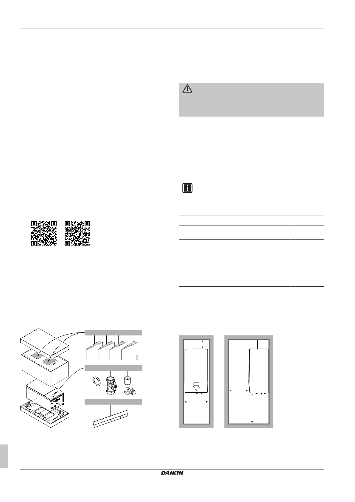
2 About the box
1× 1× 1× 1×
a b c d
2×4× 1×
fe g
1×
h
H≥1150
≥200
≥200
≥500
(mm)
≥450
Technical engineering data
▪ A subset of the latest technical data is available on the regional
Daikin website (publicly accessible).
▪ The full set of latest technical data is available on the Daikin
Business Portal (authentication required).
Online tools
In addition to the documentation set, some online tools are available
for installers:
▪ Daikin Technical Data Hub
▪ Central hub for technical specifications of the unit, useful tools,
digital resources, and more.
▪ Publicly accessible via https://daikintechnicaldatahub.eu.
▪ Heating Solutions Navigator
▪ Digital toolbox that offers a variety of tools to facilitate the
installation and configuration of heating systems.
▪ To access Heating Solutions Navigator, registration to the
Stand By Me platform is required. For more information, see
https://professional.standbyme.daikin.eu.
▪ Daikin e-Care
▪ Mobile app for installers and service technicians that allows you
to register, configure and troubleshoot heating systems.
▪ The mobile app can be downloaded for iOS and Android
devices using the QR codes below. Registration to the Stand
By Me platform is required to access the app.
App Store Google Play
2 About the box
2.1 Indoor unit
2.1.1 To remove the accessories from the indoor unit
Some accessories are located inside the unit. To open the unit, see
"3.2.1To open the indoor unit"[45].
h Wall bracket
3 Unit installation
3.1 Preparing the installation site
WARNING
The appliance shall be stored in a room without
continuously operating ignition sources (example: open
flames, an operating gas appliance or an operating electric
heater).
3.1.1 Installation site requirements of the indoor unit
▪ The indoor unit is designed for indoor installation only and for the
following ambient temperatures:
▪ Space heating operation: 5~30°C
▪ Space cooling operation: 5~35°C
▪ Domestic hot water production: 5~35°C
INFORMATION
Cooling is only applicable in case of:
▪ Reversible models
▪ Heating only models + conversion kit (EKHBCONV)
▪ Mind the measurement guidelines:
Maximum height difference between indoor unit and
outdoor unit
Maximum height difference between domestic hot
water tank and outdoor unit
Maximum water piping length between indoor unit
and domestic hot water tank
Maximum distance between the 3‑way valve and
the indoor unit (for installations with domestic hot
water tank)
Maximum total water piping length 50m
(a)
Precise water piping length can be determined using the Hydronic
Piping Calculation tool. The Hydronic Piping Calculation tool is
part of the Heating Solutions Navigator which can be reached via
https://professional.standbyme.daikin.eu. Please contact your
dealer if you have no access to Heating Solutions Navigator.
▪ Mind the following spacing installation guidelines:
10m
10m
10m
3m
(a)
Installation manual
4
a General safety precautions
b Addendum book for optional equipment
c Indoor unit installation manual
d Operation manual
e Sealing ring for shut-off valve
f Shut-off valve
g Overpressure bypass valve
ETBH/X16DF6V+9W
Daikin Altherma 3 H HT W
4P586453-1C – 2020.10
3.2 Opening and closing the unit
1
2
3
1
4
4
2
2
1
3
4×
2×
1
2
1
2
3
2×
3
1
2
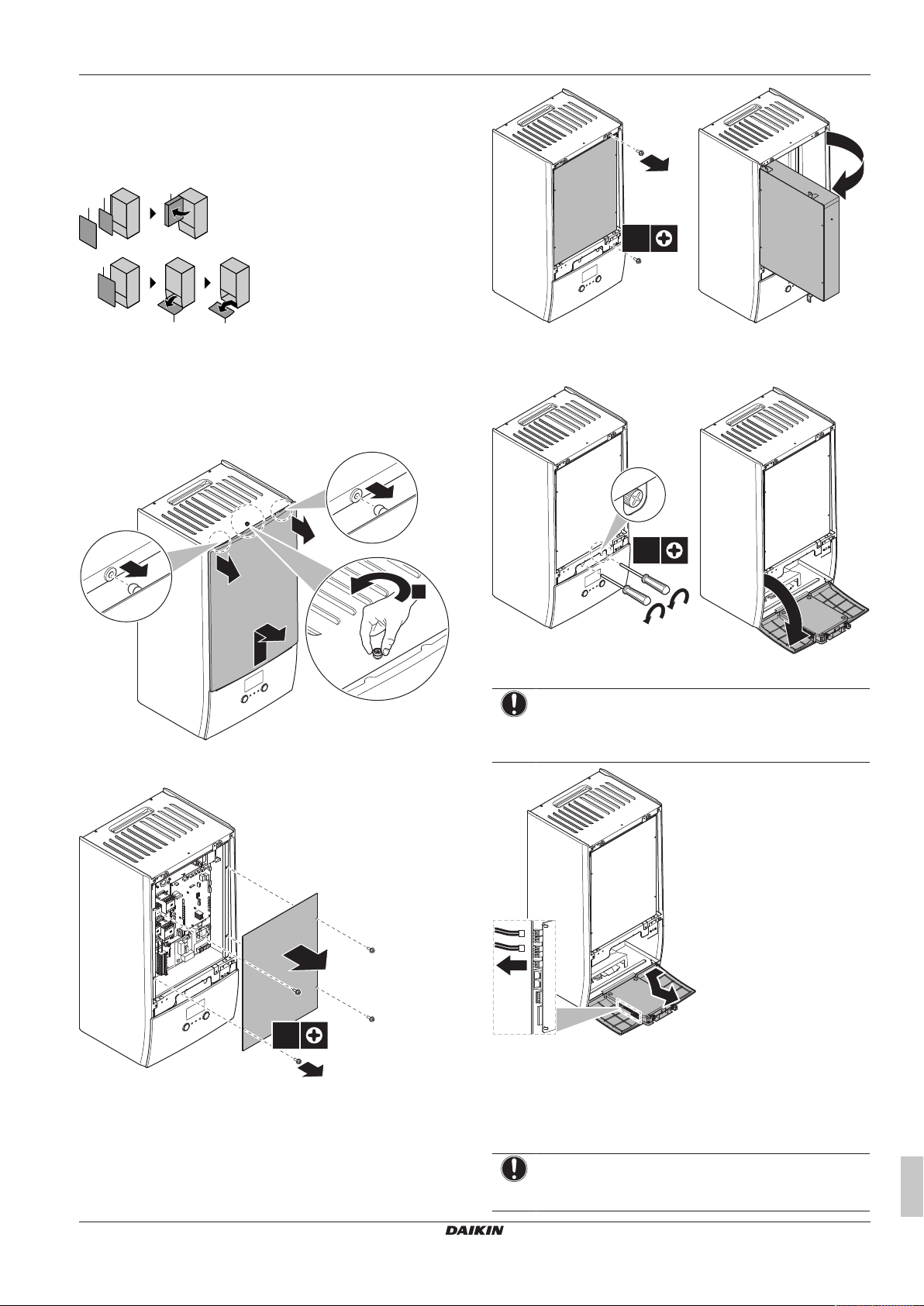
3.2.1 To open the indoor unit
Overview
3 Unit installation
1 Front panel
2 Switch box cover
3 Switch box
4 User interface panel
Open
1 Remove the front panel.
2 If you have to connect electrical wiring, remove the switch box
cover.
4 If you have to do work behind the user interface panel or upload
new software into the user interface, open the user interface
panel.
5 Optional: Remove the user interface panel.
NOTICE
If you remove the user interface panel, also disconnect the
cables from the back of the user interface panel to prevent
damage.
3.2.2 To close the indoor unit
3 If you have to do work behind the switch box, open the switch
box.
ETBH/X16DF6V+9W
Daikin Altherma 3 H HT W
4P586453-1C – 2020.10
1 Reinstall the user interface panel.
2 Reinstall the switch box cover and close the switch box.
3 Reinstall the front panel.
NOTICE
When closing the indoor unit cover, make sure that the
tightening torque does NOT exceed 4.1N•m.
Installation manual
5
4 Piping installation
2×
a
42 kg
a
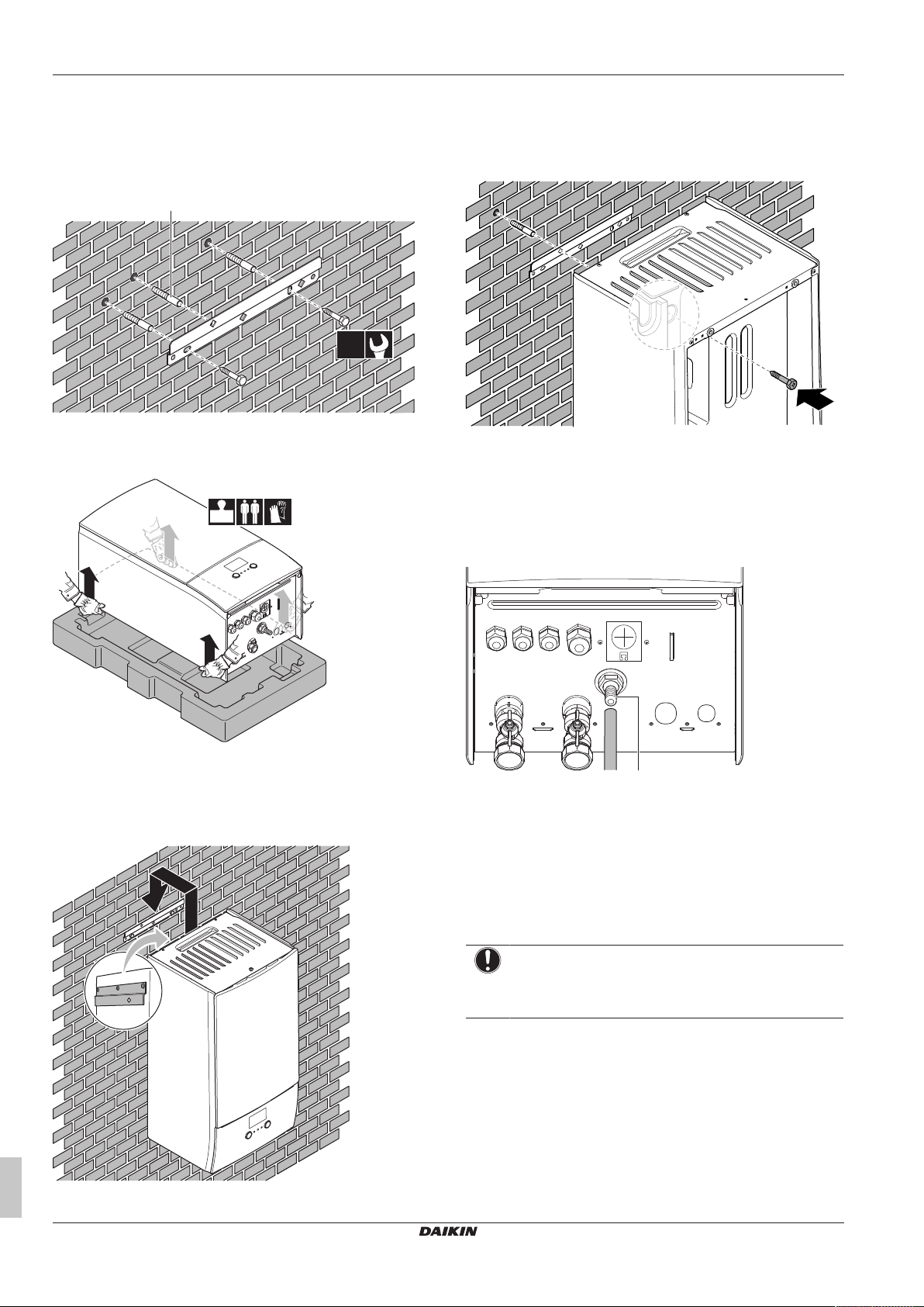
3.3 Mounting the indoor unit
3.3.1 To install the indoor unit
1 Fix the wall bracket (accessory) to the wall (level) with 2 Ø8mm
bolts.
a Optional: If you want to fix the unit to the wall from inside
the unit, provide an additional screw plug.
2 Lift the unit.
4 Optional: If you want to fix the unit to the wall from inside the
unit:
▪ Remove the upper front panel, and open the switch box. See
"3.2.1To open the indoor unit"[45].
▪ Fix the unit to the wall with an Ø8mm screw.
3.3.2 To connect the drain hose to the drain
Water coming from the pressure relief valve is collected in the drain
pan. You must connect the drain pan to an appropriate drain
according to the applicable legislation.
1 Connect a drain tube (field supply) to the drain pan connector
as follows:
3 Attach the unit to the wall bracket:
▪ Tilt the top of the unit against the wall at the position of the
wall bracket.
▪ Slide the bracket on the back of the unit over the wall
bracket. Make sure the unit is fixed properly.
a Drain pan connector
It is recommended to use a tundish to collect the water.
4 Piping installation
4.1 Preparing water piping
NOTICE
In case of plastic pipes, make sure they are fully oxygen
diffusion tight according to DIN 4726. The diffusion of
oxygen into the piping can lead to excessive corrosion.
4.1.1 To check the water volume and flow rate
Minimum water volume
Check that the total water volume in the installation is minimum 20
litres, the internal water volume of the outdoor unit NOT included.
Installation manual
6
ETBH/X16DF6V+9W
Daikin Altherma 3 H HT W
4P586453-1C – 2020.10
4 Piping installation
b a
NOTICE
When circulation in each space heating/cooling loop is
controlled by remotely controlled valves, it is important that
the minimum water volume is guaranteed, even if all of the
valves are closed.
Minimum flow rate
Check that the minimum flow rate in the installation is guaranteed in
all conditions. This minimum flow rate is required during defrost/
backup heater operation. For this purpose, use the overpressure
bypass valve delivered with the unit, and respect the minimum water
volume.
Minimum required flow rate
25l/min
NOTICE
To guarantee proper operation it is recommended to have
a minimum flow of 28l/min during DHW.
NOTICE
If glycol was added to the water circuit, and the
temperature of the water circuit is low, the flow rate will
NOT be displayed on the user interface. In this case, the
minimum flow rate can be checked by way of the pump
test (check that the user interface does NOT display error
7H).
NOTICE
When circulation in each or certain space heating loops is
controlled by remotely controlled valves, it is important that
the minimum flow rate is guaranteed, even if all valves are
closed. In case the minimum flow rate cannot be reached,
a flow error 7H will be generated (no heating or operation).
See the installer reference guide for more information.
See the recommended procedure as described in "7.2 Checklist
during commissioning"[427].
4.1.2 Third-party tank requirements
In case of a third-party tank, the tank shall adhere to the following
requirements:
▪ The heat exchanger coil of the tank is ≥1.05m².
▪ The tank thermistor must be located above the heat exchanger
coil.
▪ The booster heater must be located above the heat exchanger
coil.
NOTICE
Performance. Performance data for third-party tanks
CANNOT be provided, and performance CANNOT be
guaranteed.
NOTICE
Configuration. Configuration of a third-party tank depends
on the size of the heat exchanger coil of the tank. For more
information, see the installer reference guide.
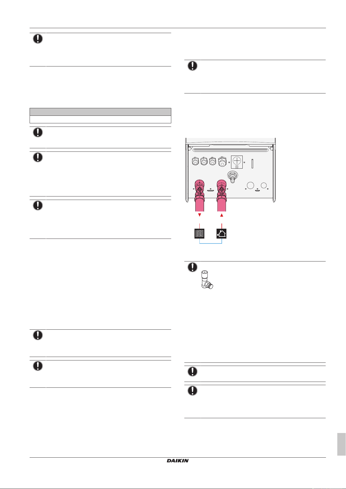
4.2 Connecting water piping
4.2.1 To connect the water piping
NOTICE
Do NOT use excessive force when connecting the field
piping and make sure the piping is aligned properly.
Deformation of the piping can cause malfunctioning of the
unit.
1 Connect the O-rings and shut-off valves to the indoor unit water
connections.
2 Connect the outdoor unit field piping on the water IN connection
(a) of the indoor unit.
3 Connect the space heating/cooling field piping on the space
heating water OUT connection (b) of the indoor unit.
a Water IN (screw connection, 1")
b Space heating water OUT (screw connection, 1")
NOTICE
Overpressure bypass valve (delivered as accessory). We
recommend to install the overpressure bypass valve in the
space heating water circuit.
▪ Mind the minimum water volume when choosing the
installation location of the overpressure bypass valve
(at the indoor unit, or at the collector). See "4.1.1To
check the water volume and flow rate"[46].
▪ Mind the minimum flow rate when adjusting the
overpressure bypass valve setting. See "4.1.1 To
check the water volume and flow rate" [4 6] and
"7.2.1To check the minimum flow rate"[428].
NOTICE
Install air purge valves at all local high points.
NOTICE
A pressure relief valve (field supply) with an opening
pressure of maximum 10bar (=1 MPa) must be installed
on the domestic cold water inlet connection in accordance
with the applicable legislation.
ETBH/X16DF6V+9W
Daikin Altherma 3 H HT W
4P586453-1C – 2020.10
4.2.2 To fill the water circuit
To fill the water circuit, use a field supply filling kit. Make sure you
comply with the applicable legislation.
Installation manual
7
4 Piping installation
NOTICE
Make sure both air purge valves (one on the magnetic filter
and one on the backup heater) are open.
All automatic air purge valves must remain open after
commissioning.
4.2.3 To protect the water circuit against freezing
About freeze protection
Frost can damage the system. To prevent the hydraulic components
from freezing, the software is equipped with special frost protection
functions such as water pipe freeze prevention and drain prevention
(see the installer reference guide) that include the activation of pump
in case of low temperatures.
However, in case of a power failure, these functions cannot
guarantee protection.
Do one of the following to protect the water circuit against freezing:
▪ Add glycol to the water. Glycol lowers the freezing point of the
water.
▪ Install freeze protection valves. Freeze protection valves drain the
water from the system before it can freeze.
NOTICE
If you add glycol to the water, do NOT install freeze
protection valves. Possible consequence: Glycol leaking
out of the freeze protection valves.
Freeze protection by glycol
About freeze protection by glycol
Adding glycol to the water lowers the freezing point of water.
WARNING
Ethylene glycol is toxic.
WARNING
Due to the presence of glycol, corrosion of the system is
possible. Uninhibited glycol will turn acidic under the
influence of oxygen. This process is accelerated by the
presence of copper and high temperatures. The acidic
uninhibited glycol attacks metal surfaces and forms
galvanic corrosion cells that cause severe damage to the
system. Therefore it is important that:
▪ the water treatment is correctly executed by a qualified
water specialist,
▪ a glycol with corrosion inhibitors is selected to
counteract acids formed by the oxidation of glycols,
▪ no automotive glycol is used because their corrosion
inhibitors have a limited lifetime and contain silicates
which can foul or plug the system,
▪ galvanized pipes are NOT used in glycol systems since
the presence may lead to the precipitation of certain
components in the glycol's corrosion inhibitor.
NOTICE
Glycol absorbs water from its environment. Therefore do
NOT add glycol that has been exposed to air. Leaving the
cap off the glycol container causes the concentration of
water to increase. The glycol concentration is then lower
than assumed. As a result, the hydraulic components
might freeze up after all. Take preventive actions to ensure
a minimal exposure of the glycol to air.
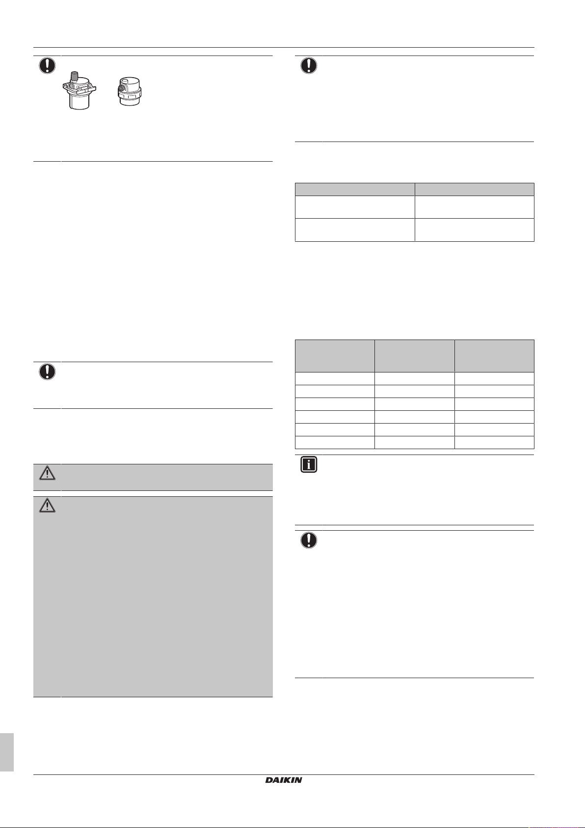
Types of glycol
The types of glycol that can be used depend on whether the system
contains a domestic hot water tank:
If… Then…
The system contains a domestic
Only use propylene glycol
(a)
hot water tank
The system does NOT contain a
domestic hot water tank
(a)
Propylene glycol, including the necessary inhibitors, classified as
CategoryIII according to EN1717.
You can use either propylene
(a)
glycol
or ethylene glycol
Required concentration of glycol
The required concentration of glycol depends on the lowest
expected outdoor temperature, and on whether you want to protect
the system from bursting or from freezing. To prevent the system
from freezing, more glycol is required.
Add glycol according to the table below.
Lowest expected
outdoor
Prevent from
bursting
Prevent from
freezing
temperature
–5°C 10% 15%
–10°C 15% 25%
–15°C 20% 35%
–20°C 25% —
–25°C 30% —
–30°C 35% —
INFORMATION
▪ Protection against bursting: the glycol will prevent the
piping from bursting, but NOT the liquid inside the
piping from freezing.
▪ Protection against freezing: the glycol will prevent the
liquid inside the piping from freezing.
NOTICE
▪ The required concentration might differ depending on
the type of glycol. ALWAYS compare the requirements
from the table above with the specifications provided by
the glycol manufacturer. If necessary, meet the
requirements set by the glycol manufacturer.
▪ The added concentration of glycol should NEVER
exceed 35%.
▪ If the liquid in the system is frozen, the pump will NOT
be able to start. Mind that if you only prevent the
system from bursting, the liquid inside might still freeze.
▪ When water is at standstill inside the system, the
system is very likely to freeze and get damaged.
Glycol and the maximum allowed water volume
Adding glycol to the water circuit reduces the maximum allowed
water volume of the system. For more information, see the installer
reference guide (topic "To check the water volume and flow rate").
Installation manual
8
ETBH/X16DF6V+9W
Daikin Altherma 3 H HT W
4P586453-1C – 2020.10
5 Electrical installation
Glycol setting
NOTICE
If glycol is present in the system, setting [E-0D] must be
set to 1. If the glycol setting is NOT set correctly, the liquid
inside the piping can freeze.
Freeze protection by freeze protection valves
About freeze protection valves
When no glycol is added to the water, you can use freeze protection
valves to drain the water from the system before it can freeze.
▪ Install freeze protection valves (field supply) at all lowest points of
the field piping.
▪ Normally closed valves (located indoors near the piping entry/exit
points) can prevent that all water from indoor piping is drained
when the freeze protection valves open.
NOTICE
When freeze protection valves are installed, set the
minimum cooling setpoint (default=7°C) at least 2°C higher
than the maximum opening temperature of the freeze
protection valve. If lower, freeze protection valves can
open during cooling operation.
For more information, see the installer reference guide.
4.2.4 To fill the domestic hot water tank
See the installation manual of the domestic hot water tank.
4.2.5 To insulate the water piping
The piping in the complete water circuit MUST be insulated to
prevent condensation during cooling operation and reduction of the
heating and cooling capacity.
Outdoor water piping insulation
See the installation manual of the outdoor unit, or the installer
reference guide.
5 Electrical installation
DANGER: RISK OF ELECTROCUTION
WARNING
ALWAYS use multicore cable for power supply cables.
INFORMATION
When installing field supply or option cables, foresee
sufficient cable length. This will make it possible to open
the switch box and gain access to other components
during service.
CAUTION
Do NOT push or place redundant cable length in the unit.
NOTICE
The distance between the high voltage and low voltage
cables should be at least 50mm.
5.1 About electrical compliance
Only for the backup heater of the indoor unit
See "5.3.2To connect the backup heater power supply"[412].
5.2 Guidelines when connecting the electrical wiring
Tightening torques
Indoor unit:
Item Tightening torque (N•m)
M4 (X1M, X2M, X5M) 1.2~1.5
M4 (earth)
5.3 Connections to the indoor unit
Item Description
Power supply (main) See "5.3.1To connect the main power
supply"[411].
Power supply (backup
heater)
Shut-off valve See "5.3.3To connect the shut-off
Electricity meters See "5.3.4To connect the electricity
Domestic hot water
pump
Alarm output See "5.3.6To connect the alarm
Space cooling/heating
operation control
Changeover to
external heat source
control
Power consumption
digital inputs
Safety thermostat See "5.3.10To connect the safety
Room thermostat
(wired or wireless)
See "5.3.2To connect the backup heater
power supply"[412].
valve"[413].
meters"[414].
See "5.3.5To connect the domestic hot
water pump"[414].
output"[414].
See "5.3.7To connect the space cooling/
heating ON/OFF output"[415].
See "5.3.8To connect the changeover to
external heat source"[415].
See "5.3.9To connect the power
consumption digital inputs"[416].
thermostat (normally closed
contact)"[416].
See:
▪ Installation manual of the wireless
room thermostat
▪ Installation manual of the wired
room thermostat (digital or
analogue) + multi-zoning base
unit
▪ Connection of the wired room
thermostat (digital or analogue)
to the multi-zoning base unit
▪ Connection of the multi-zoning
base unit to the indoor unit
▪ For cooling/heating operation,
you also need option EKRELAY1
▪ Addendum book for optional
equipment
Wires: 0.75mm²
Maximum running current: 100mA
For the main zone:
▪ [2.9] Control
▪ [2.A] Thermostat type
For the additional zone:
▪ [3.A] Thermostat type
▪ [3.9] (read-only) Control
ETBH/X16DF6V+9W
Daikin Altherma 3 H HT W
4P586453-1C – 2020.10
Installation manual
9
5 Electrical installation
Item Description
Heat pump convector There are different controllers and
setups possible for the heat pump
convectors.
Depending on the setup, you also
need option EKRELAY1.
For more information, see:
▪ Installation manual of the heat
pump convectors
▪ Installation manual of the heat
pump convector options
▪ Addendum book for optional
equipment
Wires: 0.75mm²
Maximum running current: 100mA
For the main zone:
▪ [2.9] Control
▪ [2.A] Thermostat type
For the additional zone:
▪ [3.A] Thermostat type
▪ [3.9] (read-only) Control
Remote outdoor
sensor
Remote indoor sensor See:
Human Comfort
Interface
See:
▪ Installation manual of the remote
outdoor sensor
▪ Addendum book for optional
equipment
Wires: 2×0.75mm²
[9.B.1]=1 (External sensor =
Outdoor)
[9.B.2] Ext. amb. sensor offset
[9.B.3] Averaging time
▪ Installation manual of the remote
indoor sensor
▪ Addendum book for optional
equipment
Wires: 2×0.75mm²
[9.B.1]=2 (External sensor = Room)
[1.7] Room sensor offset
See:
▪ Installation and operation manual of
the Human Comfort Interface
▪ Addendum book for optional
equipment
Wires: 2×(0.75~1.25mm²)
Maximum length: 500m
[2.9] Control
[1.6] Room sensor offset
Item Description
(in case of DHW tank)
3‑way valve
(in case of DHW tank)
Domestic hot water
tank thermistor
(in case of DHW tank)
Power supply for
booster heater and
thermal protection
(from indoor unit)
(in case of DHW tank)
Power supply for
booster heater (to
indoor unit)
WLAN adapter See:
LAN adapter See:
See:
▪ Installation manual of the 3-way
▪ Addendum book for optional
Wires: 3×0.75mm²
Maximum running current: 100mA
[9.2] Domestic hot water
See:
▪ Installation manual of the domestic
▪ Addendum book for optional
Wires: 2
The thermistor and connection wire
(12m) are delivered with the domestic
hot water tank.
[9.2] Domestic hot water
See:
▪ Installation manual of the DHW
▪ Addendum book for optional
Wires: (4+GND)×2.5mm²
[9.4] Booster heater
See:
▪ Installation manual of the domestic
▪ Addendum book for optional
Wires: 2+GND
Maximum running current: 13A
[9.4] Booster heater
▪ Installation manual of the WLAN
▪ Addendum book for optional
Use the cable delivered with the
WLAN adapter.
[D] Wireless gateway
▪ Installation manual of the LAN
▪ Addendum book for optional
Wires: 2×(0.75~1.25mm²). Must be
sheathed.
Maximum length: 200m
See below ("LAN adapter – System
requirements").
valve
equipment
hot water tank
equipment
tank
equipment
hot water tank
equipment
adapter
equipment
adapter
equipment
Installation manual
10
ETBH/X16DF6V+9W
Daikin Altherma 3 H HT W
4P586453-1C – 2020.10
LAN adapter – System requirements
1
2
3
B
C
A
A
a
1 2 3
CB
1 2 3
X11YA X11YB
X11Y
X1A
A1P
X2M
X1M
X2M
A1P
a
X1M
NL
56
B
C
A
A
10 9
S1S
1 2 3
1N~, 50 Hz,
230 V AC, 6.3 A
The requirements posed on the system depend on the LAN adapter
application/system layout (app control, or Smart Grid application).
App control:
Item Requirement
LAN adapter software It is recommended to ALWAYS keep the
LAN adapter software up-to-date.
Unit control method On the user interface, make sure to set
[2.9]=2 (Control = Room thermostat)
Smart Grid application:
Item Requirement
LAN adapter software It is recommended to ALWAYS keep the
LAN adapter software up-to-date.
Unit control method On the user interface, make sure to set
[2.9]=2 (Control = Room thermostat)
Domestic hot water
settings
To allow for energy buffering in the domestic
hot water tank, on the user interface, make
sure to set [9.2.1] (Domestic hot water) to
one of the following:
▪ EKHWS/E
Tank with booster heater installed at the
side of the tank.
▪ EKHWP/HYC
Tank with optional booster heater installed
at the top of the tank.
Power consumption
control settings
On the user interface, make sure to set:
▪ [9.9.1]=1 (Power consumption control
= Continuous)
▪ [9.9.2]=1 (Type = kW)
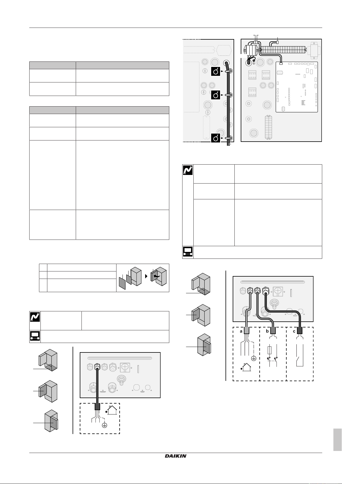
5.3.1 To connect the main power supply
1 Open the following (see "3.2.1To open the indoor unit"[45]):
1 Front panel
2 Switch box cover
3 Switch box
5 Electrical installation
a Interconnection cable (=main power supply)
In case of preferential kWh rate power supply
Interconnection
cable (=main
power supply)
Normal kWh rate
power supply
Preferential kWh
rate power supply
contact
[9.8] Benefit kWh power supply
Connect X11Y to X11YB.
Wires: (3+GND)×1.5mm²
Wires: 1N
Maximum running current: 6.3A
Wires: 2×(0.75~1.25mm²)
Maximum length: 50m.
Preferential kWh rate power supply
contact: 16VDC detection (voltage
supplied by PCB). The voltage-free
contact shall ensure the minimum
applicable load of 15VDC, 10mA.
2 Connect the main power supply.
In case of normal kWh rate power supply
Interconnection
Wires: (3+GND)×1.5mm²
cable (=main
power supply)
—
ETBH/X16DF6V+9W
Daikin Altherma 3 H HT W
4P586453-1C – 2020.10
Installation manual
11
 Loading...