

Daikin EDHQ011AA6V3, EDHQ014AA6V3, EDHQ016AA6V3, EDHQ011AA6W1, EDHQ014AA6W1 Installation manuals
...
INSTALLATION MANUAL
Unit for air to water heat pump system
EDHQ011AA6V3
EDHQ014AA6V3
EDHQ016AA6V3
EDHQ011AA6W1
EDHQ014AA6W1
EDHQ016AA6W1
EDLQ011AA6V3
EDLQ014AA6V3
EDLQ016AA6V3
EDLQ011AA6W1
EDLQ014AA6W1
EDLQ016AA6W1
EBHQ011AA6V3
EBHQ014AA6V3
EBHQ016AA6V3
EBHQ011AA6W1
EBHQ014AA6W1
EBHQ016AA6W1
EBLQ011AA6V3
EBLQ014AA6V3
EBLQ016AA6V3
EBLQ011AA6W1
EBLQ014AA6W1
EBLQ016AA6W1
D2D2
L1
L2
B1
B2
D2D2
L1
L2
1
B2
B2
D2
D2D2
EE
L1
L1
CC
HH
B1B1B1
L2
L2
AA
D1D1D1
1
B2B2B2
D2D2
D2
EE
L1
CC
L2
L2
AA
D1D1D1
L1
HH
B1
B1
1
2
1
2
W1V3
AC
AC
DCACDCAC
2

.
07
01
02
03
04
05
06
07
08
09
10
11
12
13
14
15
16
17
18
19
20
21
22
23
24
25
01
02
03
04
05
06
07
08
09
10
11
12
13
14
15
16
17
18
19
20
21
22
23
24
25
01
02
03
04
05
06
07
08
09
10
11
12
13
14
15
16
17
18
19
20
21
22
23
24
25
.
.
.
.
*
.
. 07
*
.
.
.
.
.
.
.
i
.
.
.
*
.
.
.
.
.
*
01
02
03
04
05
06
08
09
10
11
12
13
14
15
16
17
18
19
20
21
22
23
24
25
Direktive z vsemi spremembami.
Direktiivid koos muudatustega.
Директиви, с техните изменения.
Direktyvose su papildymais.
Direktīvās un to papildinājumos.
Smernice, v platnom znení.
Değiştirilmiş halleriyle Yönetmelikler.
ATITIKTIES-DEKLARACIJA
ATBILSTĪBAS-DEKLARĀCIJA
VYHLÁSENIE-ZHODY
CE -
CE -
CE -
CE - UYUMLULUK-BİLDİRİSİ
<A> DAIKIN.TCF.025C14/11-2008
<B> KEMA (NB0344)
<C> 2082543.0551-QUA/EMC
v
<B>
<B>
pozitīvajam
<C> Sertifikasına
<B>
a pozitívne zistené
съгласно
<B>
положително от
szerint.
<C> tanúsítvány
a(z)
sertifikātu <C>
<A>
ir kaip teigiamai nuspręsta
un atbilstoši
<A>
<A>
osvedčením <C>
Sertifikatą <C>
vērtējumam saskaņā ar
súlade s
pagal
Cертификата <C>
kaip nustatyta
kā norādīts
ako bolo uvedené v
22 Pastaba *
23 Piezīmes *
24 Poznámka *
v
<B>
, pozytywną opinią
şi apreciat pozitiv
Certificatul <C>
<A>
<A>
in odobreno s strani
<A>
certifikatom <C>
în conformitate cu
Świadectwem <C>
<B>
de
zgodnie z dokumentacją
<B>
aşa cum este stabilit în
kot je določeno v
skladu s
tarafından olumlu olarak
<B>
‘da belirtildiği gibi ve
değerlendirildiği gibi.
<A>
göre
Not
25
ja heaks
<A>
sertifikaadile <C>
järgi vastavalt
<B>
kiidetud
nagu on näidatud dokumendis
ZJAVA O SKLADNOSTI
VASTAVUSDEKLARATSIOON
ДЕКЛАРАЦИЯ-ЗА-СЪОТВЕТСТВИЕ
CE - I
CE -
CE -
deklaruje na własną wyłączną odpowiedzialność, że urządzenia, których ta deklaracja dotyczy:
declară pe proprie răspundere că echipamentele la care se referă această declaraţie:
m
r
IZJAVA-O-USKLAĐENOSTI
DEKLARACJA-ZGODNOŚCI
DECLARAŢIE-DE-CONFORMITATE
CE - MEGFELELŐSÉGI-NYILATKOZAT
CE -
CE -
CE -
z vso odgovornostjo izjavlja, da je oprema naprav, na katero se izjava nanaša:
kinnitab oma täielikul vastutusel, et käesoleva deklaratsiooni alla kuuluv varustus:
visiška savo atsakomybe skelbia, kad įranga, kuriai taikoma ši deklaracija:
ar pilnu atbildību apliecina, ka tālāk aprakstītās iekārtas, uz kurām attiecas šī deklarācija:
vyhlasuje na vlastnú zodpovednosť, že zariadenie, na ktoré sa vzťahuje toto vyhlásenie:
декларира на своя отговорност, че оборудването, за което се отнася тази декларация:
o
x
b
tamamen kendi sorumluluğunda olmak üzere bu bildirinin ilgili olduğu donanımının aşağıdaki gibi olduğunu beyan eder:
t
v
k
w
megfelelnek az alábbi szabvány(ok)nak vagy egyéb irányadó dokumentum(ok)nak, ha azokat előírás szerint használják:
spełniają wymogi następujących norm i innych dokumentów normalizacyjnych, pod warunkiem że używane są zgodnie z naszymi
instrukcjami:
sunt în conformitate cu următorul (următoarele) standard(e) sau alt(e) document(e) normativ(e), cu condiţia ca acestea să fie utilizate în
conformitate cu instrucţiunile noastre
skladni z naslednjimi standardi in drugimi normativi, pod pogojem, da se uporabljajo v skladu z našimi navodili:
on vastavuses järgmis(t)e standardi(te)ga või teiste normatiivsete dokumentidega, kui neid kasutatakse vastavalt meie juhenditele:
съответстват на следните стандарти или други нормативни документи, при условие, че се използват съгласно нашите
инструкции:
atitinka žemiau nurodytus standartus ir (arba) kitus norminius dokumentus su sąlyga, kad yra naudojami pagal mūsų nurodymus:
tad, ja lietoti atbilstoši ražotāja norādījumiem, atbilst sekojošiem standartiem un citiem normatīviem dokumentiem:
sú v zhode s nasledovnou(ými) normou(ami) alebo iným(i) normatívnym(i) dokumentom(ami), za predpokladu, že sa používajú v súlade
s našim návodom:
ürünün, talimatlarımıza göre kullanılması koşuluyla aşağıdaki standartlar ve norm belirten belgelerle uyumludur:
Direktiver, med senere ændringer.
Direktiv, med företagna ändringar.
Direktiver, med foretatte endringer.
Direktiivejä, sellaisina kuin ne ovat muutettuina.
v platném znění.
Directives, as amended.
Direktiven, gemäß Änderung.
Directives, telles que modifiées.
Richtlijnen, zoals geamendeerd.
Directivas, según lo enmendado.
Smjernice, kako je izmijenjeno.
irányelv(ek) és módosításaik rendelkezéseit.
и оценено
z późniejszymi poprawkami.
Directivelor, cu amendamentele respective.
<A>
както е изложено в
21 Забележка *
Direttive, come da modifica.
√‰ËÁÈÒv, fiˆ˜ ¤¯Ô˘Ó ÙÚÔÔÔÈËı›.
Directivas, conforme alteração em.
Директив со всеми поправками.
igazolta a megfelelést,
<B>
alapján, a(z)
<A>
a(z)
PROHLÁŠENÍ-O-SHODĚ
CE - ERKLÆRING OM-SAMSVAR
CE - ILMOITUS-YHDENMUKAISUUDESTA
CE -
заявляет, исключительно под свою ответственность, что оборудование, к которому относится настоящее заявление:
erklærer som eneansvarlig, at udstyret, som er omfattet af denne erklæring:
deklarerar i egenskap av huvudansvarig, att utrustningen som berörs av denna deklaration innebär att:
erklærer et fullstendig ansvar for at det utstyr som berøres av denne deklarasjon, innebærer at:
ilmoittaa yksinomaan omalla vastuullaan, että tämän ilmoituksen tarkoittamat laitteet:
prohlašuje ve své plné odpovědnosti, že zařízení, k němuž se toto prohlášení vztahuje:
izjavljuje pod isključivo vlastitom odgovornošću da oprema na koju se ova izjava odnosi:
teljes felelőssége tudatában kijelenti, hogy a berendezések, melyekre e nyilatkozat vonatkozik:
u
q
s
n
j
c
y
CE - DECLARAÇÃO-DE-CONFORMIDADE СЕ - ЗАЯВЛЕНИЕ-О-СООТВЕТСТВИИ
CE - OPFYLDELSESERKLÆRING
CE - FÖRSÄKRAN-OM-ÖVERENSTÄMMELSE
CE - ¢H§ø™H ™YMMOPºø™H™
CE - DECLARACION-DE-CONFORMIDAD
CE - DICHIARAZIONE-DI-CONFORMITA
la declaración:
referencia
h
estão em conformidade com a(s) seguinte(s) norma(s) ou outro(s) documento(s) normativo(s), desde que estes sejam utilizados de
acordo com as nossas instruções:
соответствуют следующим стандартам или другим нормативным документам, при условии их использования согласно нашим
инструкциям:
overholder følgende standard(er) eller andet/andre retningsgivende dokument(er), forudsat at disse anvendes i henhold til vore
instrukser:
respektive utrustning är utförd i överensstämmelse med och följer följande standard(er) eller andra normgivande dokument, under
förutsättning att användning sker i överensstämmelse med våra instruktioner:
respektive utstyr er i overensstemmelse med følgende standard(er) eller andre normgivende dokument(er), under forutssetning av at
disse brukes i henhold til våre instrukser:
vastaavat seuraavien standardien ja muiden ohjeellisten dokumenttien vaatimuksia edellyttäen, että niitä käytetään ohjeidemme
mukaisesti:
za předpokladu, že jsou využívány v souladu s našimi pokyny, odpovídají následujícím normám nebo normativním dokumentům:
u skladu sa slijedećim standardom(ima) ili drugim normativnim dokumentom(ima), uz uvjet da se oni koriste u skladu s našim uputama:
Machinery 98/37/EC
Low Voltage 2006/95/EC
Electromagnetic Compatibility 2004/108/EC *
ob upoštevanju določb:
vastavalt nõuetele:
следвайки клаузите на:
laikantis nuostatų, pateikiamų:
ievērojot prasības, kas noteiktas:
održiavajúc ustanovenia:
bunun koşullarına uygun olarak:
under iagttagelse af bestemmelserne i:
enligt villkoren i:
gitt i henhold til bestemmelsene i:
noudattaen määräyksiä:
za dodržení ustanovení předpisu:
prema odredbama:
követi a(z):
zgodnie z postanowieniami Dyrektyw:
în urma prevederilor:
Notă *
16 Megjegyzés *
17 Uwaga *
18
on
<B>
ja jotka
enligt
<B>
och godkänts av
<A>
enligt
11 Information *
e giudicato positivamente
<A>
delineato nel
mukaisesti.
<A>
Sertifikat <C>
og gjennom positiv
<A>
ifølge
<B>
Sertifikaatin <C>
hyväksynyt
Certifikatet <C>
som det fremkommer i
bedømmelse av
jotka on esitetty asiakirjassa
12 Merk *
13 Huom *
Certificado <C>
¶ИЫЩФФИЛЩИОfi <C>
e com o parecer
Î·È ÎÚ›ÓÂÙ·È ıÂÙÈο
<A>
<A>
Certificato <C>
de acordo com o
Û‡Ìʈӷ Ì ÙÔ
<B>
<B>
secondo il
<B>
positivo de
·fi ÙÔ
tal como estabelecido em
da
* fiˆ˜ ηıÔÚ›˙ÂÙ·È ÛÙÔ
™ËÌ›ˆÛË
06 Nota *
08 Nota
<B>
positiv
<B>
<C>
<C>
et évalué positivement par
Certificat <C>
<A>
Certificate
and judged positively by
Zertifikat
aufgeführt und von
<A>
<A>
conformément au
beurteilt gemäß
according to the
as set out in
wie in der
tel que défini dans
<B>
19 Opomba *
20 Märkus
v
<B>
a pozitivně zjištěno
i pozitivno ocijenjeno od
<A>
Certifikatu <C>
<A>
prema
osvědčením <C>
<B>
strane
jak bylo uvedeno v
kako je izloženo u
souladu s
14 Poznámka *
15 Napomena *
i
<B>
согласно
<B>
и в соответствии с
og positivt vurderet af
<A>
<A>
Certifikat <C>
положительным решением
henhold til
как указано в
Свидетельству <C>
som anført i
09 Примечание *
10 Bemærk *
y es valorado
de acuerdo con el
<A>
Certificaat <C>
en positief beoordeeld door
<B>
<A>
overeenkomstig
zoals vermeld in
<B>
como se establece en
Certificado <C>
positivamente por
Jiro Tomita
Director Quality Assurance
Ostend, 1st of February 2009
declares under its sole responsibility that the equipment to which this declaration relates:
erklärt auf seine alleinige Verantwortung, dass die Ausrüstung für die diese Erklärung bestimmt ist:
déclare sous sa seule responsabilité que l’équipement visé par la présente déclaration:
verklaart hierbij op eigen exclusieve verantwoordelijkheid dat de apparatuur waarop deze verklaring betrekking heeft:
declara bajo su única responsabilidad que el equipo al que hace
a
d
f
l
CE - DECLARATION-OF-CONFORMITY
CE - KONFORMITÄTSERKLÄRUNG
CE - DECLARATION-DE-CONFORMITE
CE - CONFORMITEITSVERKLARING
Daikin Europe N.V.
e
dichiara sotto la propria responsabilità che gli apparecchi a cui è riferita questa dichiarazione:
declara sob sua exclusiva responsabilidade que os equipamentos a que esta declaração se refere:
‰ЛПТУВИ МВ ·ФОПВИЫЩИО‹ ЩЛ˜ В˘ı‡УЛ fiЩИ Ф ВНФПИЫМfi˜ ЫЩФУ ФФ›Ф ·У·К¤ЪВЩ·И Л ·ЪФ‡Ы· ‰‹ПˆЫЛ:
i
p
g
EDLQ011AA6V3, EDLQ011AA6W1, EDLQ014AA6V3, EDLQ014AA6W1, EDLQ016AA6V3, EDLQ016AA6W1, EDHQ011AA6V3, EDHQ011AA6W1, EDHQ014AA6V3, EDHQ014AA6W1, EDHQ016AA6V3, EDHQ016AA6W1,
are in conformity with the following standard(s) or other normative document(s), provided that these are used in accordance with our
instructions:
der/den folgenden Norm(en) oder einem anderen Normdokument oder -dokumenten entspricht/entsprechen, unter der Voraussetzung,
daß sie gemäß unseren Anweisungen eingesetzt werden:
sont conformes à la/aux norme(s) ou autre(s) document(s) nor matif(s), pour autant qu'ils soient utilisés conformément à nos instructions:
conform de volgende norm(en) of één of meer andere bindende documenten zijn, op voorwaarde dat ze worden gebruikt overeenkomstig
onze instructies:
están en conformidad con la(s) siguiente(s) norma(s) u otro(s) documento(s) nor mativo(s), siempre que sean utilizados de acuerdo con
nuestras instrucciones:
sono conformi al(i) seguente(i) standard(s) o altro(i) documento(i) a carattere normativo, a patto che vengano usati in conformità alle
nostre istruzioni:
В›У·И Ы‡МКˆУ· МВ ЩФ(·) ·ОfiПФ˘ıФ(·) ЪfiЩ˘Ф(·) ‹ ¿ППФ ¤ББЪ·КФ(·) О·УФУИЫМТУ, ˘fi ЩЛУ ЪФ¸fiıВЫЛ fiЩИ ¯ЪЛЫИМФФИФ‡УЩ·И
EBLQ011AA6V3, EBLQ011AA6W1, EBLQ014AA6V3, EBLQ014AA6W1, EBLQ016AA6V3, EBLQ016AA6W1, EBHQ011AA6V3, EBHQ011AA6W1, EBHQ014AA6V3, EBHQ014AA6W1, EBHQ016AA6V3, EBHQ016AA6W1,
Û‡Ìʈӷ Ì ÙȘ Ô‰ËÁ›Â˜ Ì·˜:
following the provisions of:
gemäß den Vorschriften der:
conformément aux stipulations des:
EN60335-2-40,
overeenkomstig de bepalingen van:
siguiendo las disposiciones de:
secondo le prescrizioni per:
Ì ًÚËÛË Ùˆv ‰È·Ù¿Íˆv Ùˆv:
de acordo com o previsto em:
в соответствии с положениями:
01 Note *
02 Hinweis *
03 Remarque *
04 Bemerk *
05 Nota
3PW33163-2B
EDHQ011~016AA6V3 EDHQ011~016AA6W1
EDLQ011~016AA6V3 EDLQ011~016AA6W1
EBHQ011~016AA6V3 EBHQ011~016AA6W1
EBLQ011~016AA6V3 EBLQ011~016AA6W1
Unit for air to water heat pump system
Installation manual
CONTENTS Page
Introduction ....................................................................................... 1
General information ................................................................................... 1
Scope of this manual ................................................................................. 2
Model identification.................................................................................... 2
Accessories....................................................................................... 2
Accessories supplied with the unit............................................................. 2
Safety considerations........................................................................ 2
Before installation.............................................................................. 3
Important information regarding the refrigerant used........................ 3
Selecting installation site................................................................... 4
Selecting a location in cold climates.......................................................... 4
Precautions on installation ................................................................4
Drain work.................................................................................................. 5
Installation method for prevention of falling over........................................ 5
Installation servicing space........................................................................ 5
Typical application examples............................................................. 6
Application 1 .............................................................................................. 6
Application 2 .............................................................................................. 6
Application 3 .............................................................................................. 7
Application 4 .............................................................................................. 7
Overview of the unit .......................................................................... 8
Opening the unit ........................................................................................ 8
Main components ...................................................................................... 8
Water pipework........................................................................................ 10
Charging water ........................................................................................ 12
Piping insulation....................................................................................... 12
Field wiring .............................................................................................. 12
Installation of the digital controller ........................................................... 18
Start-up and configuration............................................................... 19
DIP switch settings overview ................................................................... 19
Room thermostat installation configuration ............................................. 19
Pump operation configuration.................................................................. 19
Domestic hot water tank installation configuration................................... 20
Initial start-up at low outdoor ambient temperatures ............................... 20
Pre-operation checks............................................................................... 20
Powering up the unit ................................................................................ 20
Setting the pump speed........................................................................... 20
Field settings............................................................................................ 21
Field settings table................................................................................... 27
Test run and final check .................................................................. 29
Automatic test run.................................................................................... 29
Test run operation (manual)..................................................................... 29
Final check............................................................................................... 29
Maintenance.................................................................................... 29
Troubleshooting............................................................................... 30
General guidelines................................................................................... 30
General symptoms................................................................................... 30
Error codes .............................................................................................. 31
Technical specifications................................................................... 33
General.................................................................................................... 33
Electrical specifications ........................................................................... 33
READ THESE INSTRUCTIONS CAREFULLY BEFORE
INSTALLATION. KEEP THIS MANUAL IN A HANDY
PLACE FOR FUTURE REFERENCE.
IMPROPER INSTALLATION OR ATTACHMENT OF
EQUIPMENT OR ACCESSORIES COULD RESULT IN
ELECTRIC SHOCK, SHORT-CIRCUIT, LEAKS, FIRE OR
OTHER DAMAGE TO THE EQUIPMENT. BE SURE ONLY
TO USE ACCESSORIES MADE BY DAIKIN WHICH ARE
SPECIFICALLY DESIGNED FOR USE WITH THE
EQUIPMENT AND HAVE THEM INSTALLED BY A
PROFESSIONAL.
IF UNSURE OF INSTALLATION PROCEDURES OR USE,
ALWAYS CONTACT YOUR DAIKIN DEALER FOR
ADVICE AND INFORMATION.
The English text is the original instruction. Other languages are
translations of the original instructions.
INTRODUCTION
General information
Thank you for purchasing this AD outdoor
monoblock unit.
These units are used for both heating and cooling applications. The
units can be combined with Daikin fan coil units, floor heating
applications, low temperature radiators, domestic water heating
applications and solar kit for domestic hot water applications.
Heating/cooling units and heating only units
The AD outdoor monoblock unit range consists of
two main versions: a heating/cooling (EB) version and a heating only
(ED) version.
Both versions are delivered with an integrated backup heater for
additional heating capacity during cold outdoor temperatures. The
backup heater also serves as a backup in case of malfunctioning of
the unit and for freeze protection of the outside waterpiping during
winter time. The backup heater factory set capacity is 6 kW, however,
depending on the installation, the installer can limit the backup heater
capacity to 3 kW/2 kW. The backup heater capacity decision is a
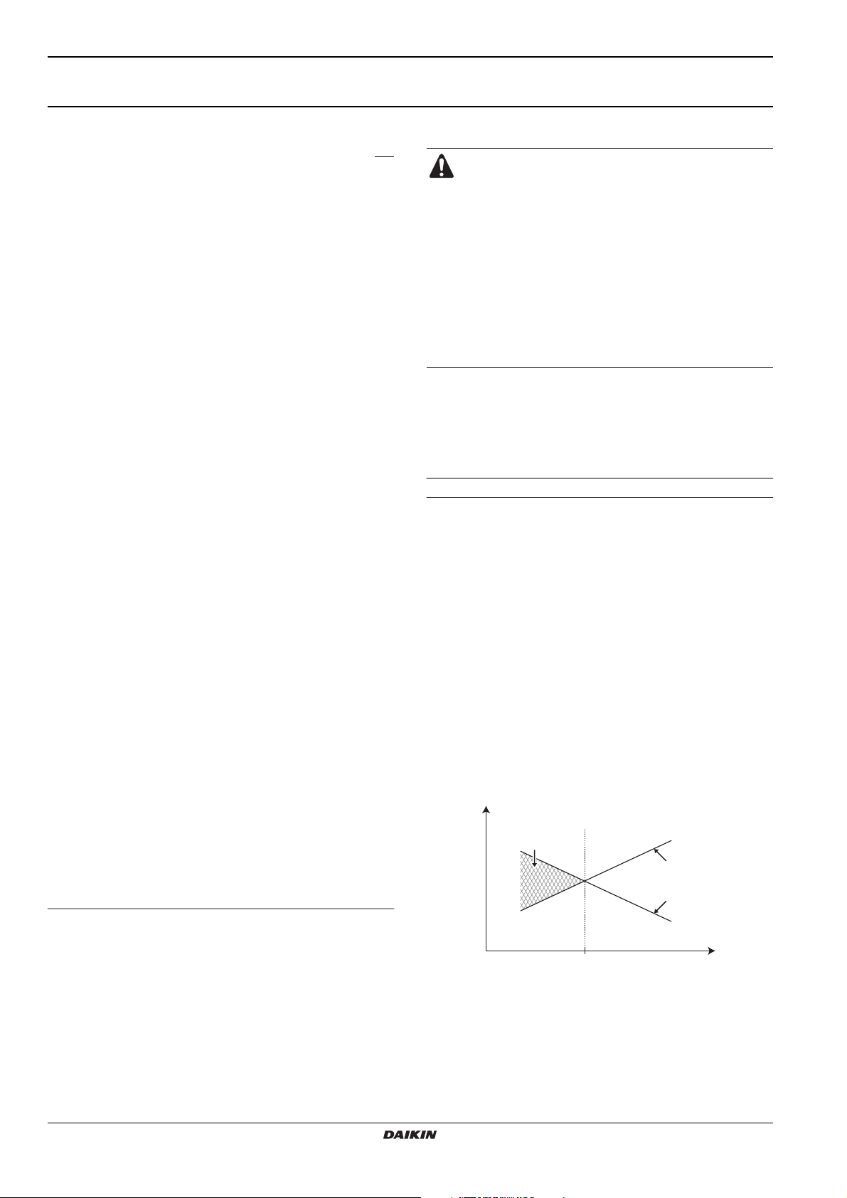
mode based on the equilibriumtemperature, see scheme below.
P
H
3
1
2
Installation manual
1
4
1 Heat pump capacity
2 Required heating capacity (site dependent)
3 Additional heating capacity provided by the backup heater
4 Equilibriumtemperature (can be set through the user interface,
refer to "Field settings" on page 21)
T
Ambient (outdoor) temperature
A
P
Heating capacity
H
E(D/B)(H/L)Q011~016AA6V3+W1
Unit for air to water heat pump system
T
A
4PW51121-1C
Options
■ Domestic hot water tank EKHW*
An optional EKHW* domestic hot water tank with integrated
3 kW electrical booster heater can be connected to the unit. The
domestic hot water tank is available in three sizes: 150, 200 and
300 litre.
■ Drain kit EKDK04
■ Bottom plate heater kit EKBPHT16Y
■ Room thermostat kits EKRTW, EKRTR and EKRTETS
■ Solar kit for domestic hot water tank EKSOLHW
■ Remote alarm kit EKRP1H
To obtain more information concerning these option kits, please refer
to dedicated installation manuals of the kits.
Connection to a benefit kWh rate power supply
This equipment allows for connection to benefit kWh rate power
supply delivery systems. Full control of the unit will remain possible
only in case the benefit kWh rate power supply is of the type that
power supply is not interrupted. Refer to "Connection to a benefit
kWh rate power supply" on page 17 for more details.
Scope of this manual
This installation manual describes the procedures for unpacking,
installing and connecting all EDH, EDL, EBH and EBL outdoor unit
models.
Model identification
ED H Q 011 AA 6 V3
Power supply:
V3 = 1~, 230 V, 50 Hz
W1 = 3N~, 400 V, 50 Hz
Backup heater capacity (kW)
Model changes
Indication of heating capacity (kW)
Refrigerant R410A
H = Low water temperature - ambient zone 3
L = Low water temperature - ambient zone 2
ED = Monoblock outdoor heating only
EB = Monoblock outdoor heatpump
(a) For exact values, refer to "Technical specifications" on page 33.
(a)
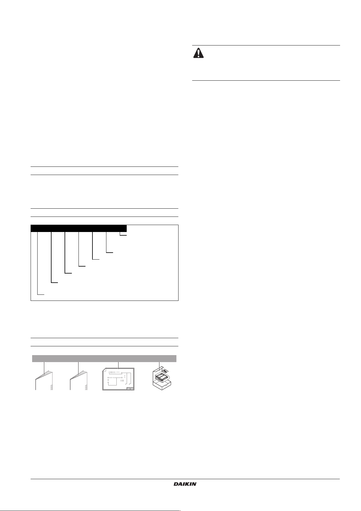
ACCESSORIES
Accessories supplied with the unit
12 3 4
1x 1x 2x 1x
1 Installation manual
2 Operation manual
3 Wiring diagram sticker (inside unit cover doors 1 and 2)
4 User interface kit
(digital remote controller, 4 fixing screws and 2 plugs)
SAFETY CONSIDERATIONS
The precautions listed here are divided into the following two types.
Both cover very important topics, so be sure to follow them carefully.
WARNING
If the warning is not observed, it may cause serious casualties.
CAUTION
If the caution is not observed, it may cause injury or damage to the
equipment.
Warning
■ For use of units in applications with temperature alarm settings it
is advised to foresee a delay of 10 minutes for signalling the
alarm in case the alarm temperature is exceeded. The unit may
stop for several minutes during normal operation for "defrosting
of the unit" or when in "thermostat-stop" operation.
■
Ask your dealer or qualified personnel to carry out installation work
Do not install the machine by yourself.
Improper installation may result in water leakage, electric shocks
or fire.
■ Perform installation work in accordance with this installation
manual.
Improper installation may lead to water leakage, electric shocks
or fire.
■ Be sure to use only the specified accessories and parts for
installation work.
Failure to use the specified parts may result in water leakage,
electric shocks, fire, or the unit falling.
■ Install the unit on a foundation that can withstand its weight.
■ Insufficient strength may result in the fall of equipment and
causing injury.
■ Carry out the specified installation work in consideration of
strong winds, typhoons, or earthquakes.
Improper installation work may result in accidents due to fall of
equipment.
■ Make certain that all electrical work is carried out by qualified
personnel according to the local laws and regulations and this
installation manual, using a separate circuit.
Insufficient capacity of the power supply circuit or improper
electrical construction may lead to electric shocks or fire.
■ Make sure that all wiring is secure, using the specified wires and
ensuring that external forces do not act on the terminal
connections or wires.
Incomplete connection or fixing may cause a fire.
■ When wiring the power supply, form the wires so that the
frontside panel can be securely fastened.
If the frontside panel is not in place, overheat of the terminals,
electric shocks or a fire may be caused.
■ After completing the installation work, check to make sure that
there is no leakage of refrigerant gas.
■ Before touching electric terminal parts, turn off power switch.
■ Live parts can be easily touched by accident.
Never leave the unit unattended during installation or servicing
when the service panel is removed.
■ Never directly touch any accidental leaking refrigerant. This
could result in severe wounds caused by frostbite.
.
E(D/B)(H/L)Q011~016AA6V3+W1
Unit for air to water heat pump system
4PW51121-1C
Installation manual
2
Caution
■ Earth the unit.
Earthing resistance should be according to national regulations
Do not connect the earth wire to gas or water pipes,
lightning conductor or telephone earth wire.
Incomplete earthing may cause electric shocks.
■ Gas pipe.
Ignition or explosion may occur if the gas leaks.
■ Water pipe.
Hard vinyl tubes are not effective earths.
■ Lightning conductor or telephone earth wire.
Electric potential may rise abnormally if struck by a lightning
bolt.
■ Be sure to install an earth leakage circuit breaker.
Failure to install an earth leakage circuit breaker may cause
electric shocks and fire.
■ Install the power wire at least 1 meter away from televisions or
radios to prevent image interference or noise.
(Depending on the radio waves, a distance of 1 meter may not
be sufficient to eliminate the noise.)
■ Do not rinse the unit. This may cause electric shocks or fire.
■ Do not install the unit in places such as the following:
■ Where there is mist of mineral oil, oil spray or vapour.
Plastic parts may deteriorate, and cause them to fall out or
water to leak.
■ Where corrosive gas, such as sulphurous acid gas, is
produced.
Corrosion of copper pipes or soldered parts may cause the
refrigerant to leak.
■ Where there is machinery which emits electromagnetic
waves.
Electromagnetic waves may disturb the control system, and
cause malfunction of the equipment.
■ Where flammable gases may leak, where carbon fiber or
ignitable dust is suspended in the air or where volatile
flammables, such as thinner or gasoline, are handled.
Such gases may cause a fire.
■ Where the air contains high levels of salt such as that near
the ocean.
■ Where voltage fluctuates a lot, such as that in factories.
■ In vehicles or vessels.
■ Where acidic or alkaline vapour is present.
BEFORE INSTALLATION
Installation
■ Be sure to confirm the model name and the serial no. of the
outer (front) plates when attaching/detaching the plates to avoid
mistakes.
■ When closing the service panels, take care that the tightening
torque does not exceed 4.1 N•m.
Model
EDL and EBL units include special equipment (insulation, heater
sheet,...) to ensure good operation in areas where low ambient
temperature can occur together with high humidity conditions. In
such conditions the EDH and EBH models may experience problems
with severe ice build up on the aircooled coil. In case such conditions
are expected, the EDL or EBL must be installed instead. These
models contain countermeasures (insulation, heater sheet,...) to
prevent freeze up.
■ Possible options
Heater sheet Drain socket
EDLQ, EBLQ Standard Use prohibited
EDHQ, EBHQ Optional kit
(a) Combination of both options is prohibited.
(a)
Optional kit
(a)
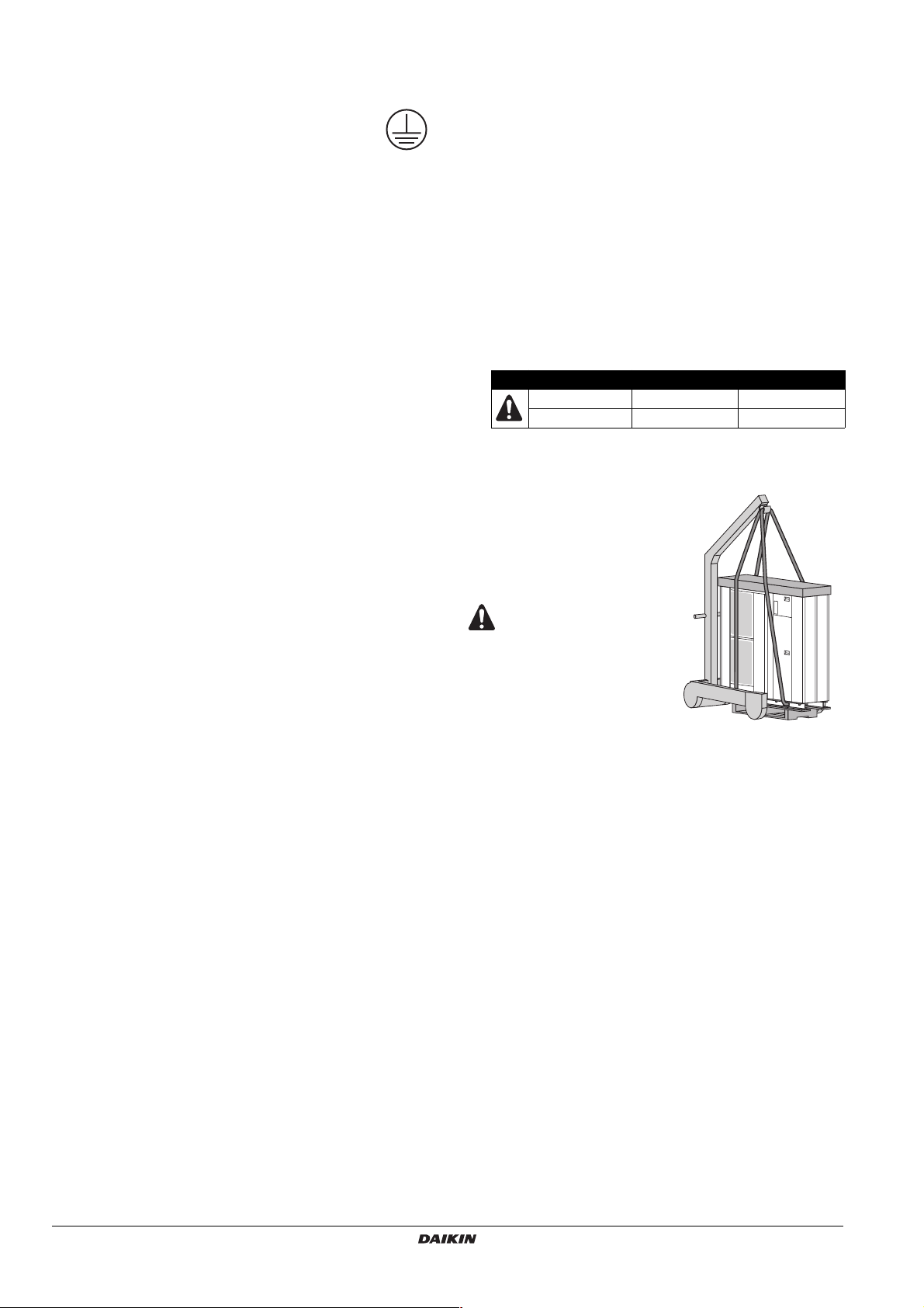
Handling
Due to relatively large dimensions
and high weight, the handling of the
unit is only to be done by means of
lifting tools with slings. These slings
can be fitted into specialy for this
purpose foreseen sleeves at the
base frame.
■ To avoid injury, do not
touch the air inlet or
aluminium fins of the
unit.
■ Do not use the grips
in the fan grills to
avoid damage.
IMPORTANT INFORMATION REGARDING THE
REFRIGERANT USED
This product contains fluorinated greenhouse gases covered by the
Kyoto Protocol. Do not vent gases into the atmosphere.
Refrigerant type: R410A
(1)
value: 1975
GWP
(1)
GWP = global warming potential
The refrigerant quantity is indicated on the unit name plate
Installation manual
3
E(D/B)(H/L)Q011~016AA6V3+W1
Unit for air to water heat pump system
4PW51121-1C
SELECTING INSTALLATION SITE
■ Make sure to provide for adequate measures in order
to prevent that the outdoor unit be used as a shelter
by small animals.
■ Small animals making contact with electrical parts can
cause malfunctions, smoke or fire. Please instruct the
customer to keep the area around the unit clean.
1 Select an installation site where the following conditions are
satisfied and that meets with your customer's approval.
- Places which are well-ventilated.
- Places where the unit does not bother next-door neighbours.
- Safe places which can withstand the unit's weight and
vibration and where the unit can be installed level.
- Places where there is no possibility of flammable gas or
product leak.
- The equipment is not intended for use in a potentially
explosive atmosphere.
- Places where servicing space can be well ensured.
- Places where the units' piping and wiring lengths come within
the allowable ranges.
- Places where water leaking from the unit cannot cause
damage to the location (e.g. in case of a blocked drain pipe).
- Places where the rain can be avoided as much as possible.
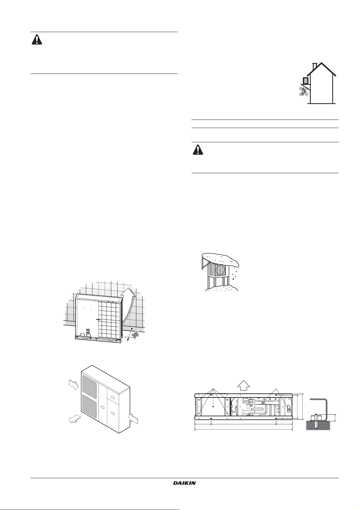
2 When installing the unit in a place exposed to strong wind, pay
special attention to the following.
Strong winds of 5 m/sec or more blowing against the unit's air
outlet causes short circuit (suction of discharge air), and this
may have the following consequences:
- Deterioration of the operational capacity.
-Frequent frost acceleration in heating operation.
- Disruption of operation due to rise of high pressure.
- When a strong wind blows continuously on the face of the
unit, the fan can start rotating very fast until it breaks.
Refer to the figures for installation of this unit in a place where
the wind direction can be foreseen.
■ Tu rn the air outlet side toward the building's wall, fence or
screen.
5 If you install the unit on a frame, please install a waterproof plate
within 150 mm of the underside of the unit in order to prevent the
invasion of water from the lower direction.
6 When installing the unit in a place frequently exposed to snow,
pay special attention to elevate the foundation as high as
possible.
7 If you install the unit on a building frame,
please install a waterproof plate (field
supply)(within 150 mm of the underside of
the unit) or use a drain kit (refer to
combination table in "Possible options" on
page 3) in order to avoid the drainwater
dripping. (See figure).
Selecting a location in cold climates
Refer to "Model" on page 3.
CAUTION
When operating the unit in a low outdoor ambient
temperature, be sure to follow the instructions described
below.
■ To prevent exposure to wind, install the unit with its suction side
facing the wall.
■ Never install the unit at a site where the suction side may be
exposed directly to wind.
■ To prevent exposure to wind, install a baffle plate on the air
discharge side of the unit.
■ In heavy snowfall areas it is very important to select an
installation site where the snow will not affect the unit. If lateral
snowfall is possible, make sure that the heat exchanger coil is
not affected by the snow (if necessary construct a lateral
canopy).
1 Construct a large canopy.
2 Construct a pedestal.
Install the unit high enough off the
ground to prevent burying in snow.
Make sure there is enough room to do the installation
■ Set the outlet side at a right angle to the direction of the wind.
Strong wind
Blown air Strong wind
3 Prepare a water drainage channel around the foundation, to
drain waste water from around the unit.
4 If the water drainage of the unit is not easy, please build up the
unit on a foundation of concrete blocks, etc. (the height of the
foundation should be maximum 150 mm).
E(D/B)(H/L)Q011~016AA6V3+W1
Unit for air to water heat pump system
4PW51121-1C
PRECAUTIONS ON INSTALLATION
■ Check the strength and level of the installation ground so that
the unit will not cause any operating vibration or noise after
installation.
■ In accordance with the foundation drawing in the figure, fix the
unit securely by means of the foundation bolts. (Prepare four
sets of M12 foundation bolts, nuts and washers each which are
available on the market.)
■ It is best to screw in the foundation bolts until their length are
20 mm from the foundation surface.
AC C
B
240 955 240
1435
A Discharge side
B Bottom view (mm)
C Drain hole
380
345
Installation manual
20
4
Drain work
Check in the combination table under "Possible options" on page 3
whether drain work is allowed. In case drain work on your unit is
allowed and the installation site requires drain work, then follow the
guidelines below.
■ Drain kits for drainage are available as option.
■ If drain work from the unit causes trouble (for example, if the
drain water may splash on people) provide the drain piping using
a drain socket (optional).
■ Make sure the drain works properly.
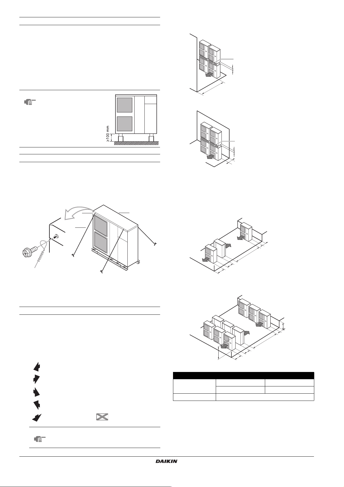
NOTE
If drain holes of the unit
are covered by a mounting
base or by floor surface,
raise the unit in order to
provide a free space of
more than 100 mm under
the unit.
(B) In case of stacked installation
1. In case obstacles exist in front of the outlet side.
A
≥100
≥1000
2. In case obstacles exist in front of the air inlet.
A
Installation method for prevention of falling over
If it is necessary to prevent the unit from falling over, install as shown
in the figure.
■ prepare all 4 wires as indicated in the drawing
■ unscrew the top plate at the 4 locations indicated A and B
■ put the screws through the nooses and screw them back tight
AA
B
C
A Location of the 2 fixation holes on the front side of the unit
B Location of the 2 fixation holes on the rear side of the unit
C Wires: field supply
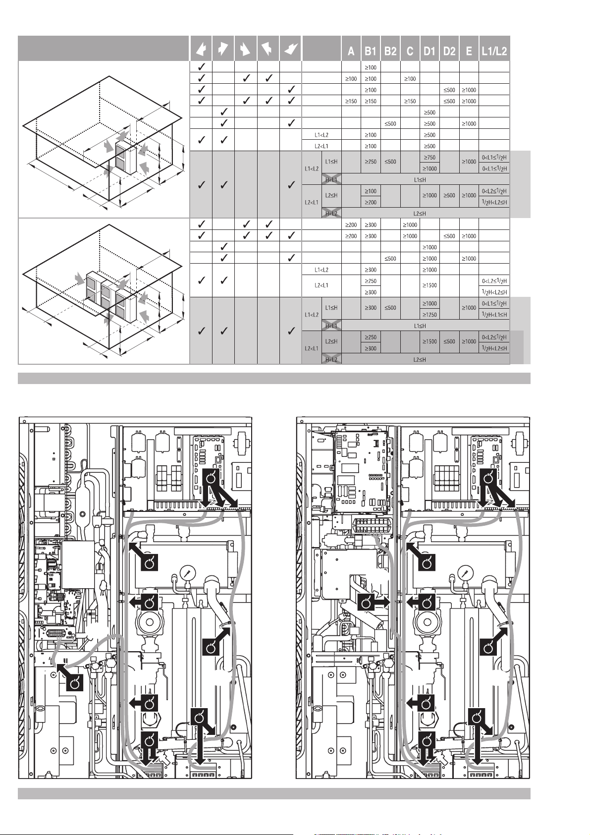
Installation servicing space
The numerical figures used in the figures represent the dimensions in
mm.
(Refer to "Precautions on installation" on page 4)
Precaution
(A) In case of non-stacked installation (See figure 1)
Suction side obstacle
Discharge side obstacle
Left side obstacle
Right side obstacle
Top side obstacle
Obstacle is present
✓
In these cases, close the
1
bottom of the installation
frame to prevent the
discharged air from
being bypassed
In these cases, only
2
2 units can be installed.
This situation is not
allowed
≥100
≥300
Do not stack more than one unit.
About 100 mm is required as the dimension for laying the upper unit's
drain pipe. Get the portion A sealed so that air from the outlet does
not bypass.
(C) In case of multiple-row installation (for roof top use, etc.)
1. In case of installing one unit per row.
≥100
≥2000
≥200
≥1000
2. In case of installing multiple units (2 units or more) in lateral
connection per row.
L
A
≥3000
H
≥600
≥1500
Relation of dimensions of H, A and L are shown in the table below.
L A
L≤H
H<L Installation not allowed
0<L≤1/2H 250
1/2H<L 300
NOTE
Installation manual
5
Minimum distance B1 in figure 1 mentions the
space required for correct operation of the unit.
Required space for servicing though is 300 mm.
E(D/B)(H/L)Q011~016AA6V3+W1
Unit for air to water heat pump system
4PW51121-1C
TYPICAL APPLICATION EXAMPLES
Application 2
When the AD system is used in series
with another heat source (e.g. gas boiler), it shall be made
sure that the return water temperature to the heat
exchanger does not exceed 55°C. Daikin shall not be held
liable for any damage resulting from not observing this
rule.
The application examples given below are for illustration purposes
only.
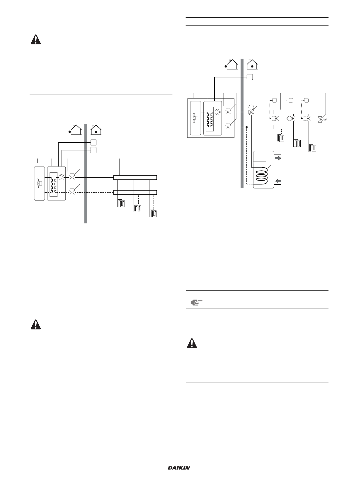
Application 1
Space heating only application with a room thermostat connected to
the unit.
I
T
4321
1 Unit FHL1..3 Floor heating loop
2 Heat exchanger
3 Pump T Room thermostat
4 Shut-off valve
5 Collector (field supply) I User interface
Unit operation and space heating
When a room thermostat (T) is connected to the unit and when there
is a heating request from the room thermostat, the unit will start
operating to achieve the target leaving water temperature as set on
the user interface.
When the room temperature is above the thermostat set point, the
unit will stop operating.
Make sure to connect the thermostat wires to the correct
terminals (see "Connection of the thermostat cable" on
page 16) and to configure the DIP switch toggle switches
correctly (see "Room thermostat installation configuration"
on page 19).
5
FHL1
FHL2
FHL3
(field supply)
(field supply)
Space heating only application without room thermostat connected to
the unit. The temperature in each room is controlled by a valve on
each water circuit. Domestic hot water is provided through the
domestic hot water tank which is connected to the unit.
I
43 721
1 Unit 9 Heat exchanger coil
2 Heat exchanger 10 Domestic hot water tank
3 Pump FHL1..3 Floor heating loop
4 Shut-off valve
5 Collector (field supply) T1..3 Individual room
6 Motorised 3-way valve
7 By-pass valve
(field supply)
8 Booster heater I User interface
6
M
M1..3 Individual motorised
5
T1
M1
M2T2M3
98
FHL1
FHL2
10
(field supply)
thermostat (field supply)
valve to control loop
FHL1 (field supply)
T3
FHL3
Pump operation
With no thermostat connected to the unit (1), the pump (3) can be
configured to operate either as long as the unit is on, or until the
required water temperature is reached.
NOTE
Details on pump configuration can be found under
"Pump operation configuration" on page 19.
Space heating
The unit (1) will operate to achieve the target leaving water
temperature as set on the user interface.
When circulation in each space heating loop (FHL1..3) is
controlled by remotely controlled valves (M1..3), it is
important to provide a by-pass valve (7) to avoid the flow
switch safety device from being activated.
The by-pass valve should be selected as such that at all
time the minimum water flow as mentioned under "Water
pipework" on page 10 is guaranteed.
E(D/B)(H/L)Q011~016AA6V3+W1
Unit for air to water heat pump system
4PW51121-1C
Installation manual
6
Domestic water heating
When domestic water heating mode is enabled (either manually by
the user, or automatically through a schedule timer) the target
domestic hot water temperature will be achieved by a combination of
the heat exchanger coil and the electrical booster heater.
When the domestic hot water temperature is below the user
configured set point, the 3-way valve will be activated to heat the
domestic water by means of the heat pump. In case of large domestic
hot water demand or a high domestic hot water temperature setting,
the booster heater (8) can provide auxiliary heating.
Pump operation and space heating and cooling
According to the season, the customer will select cooling or heating
on the room thermostat (T). This selection is not possible by
operating the user interface.
When space cooling/heating is requested by the room thermostat
(T), the pump will start operating and the unit (1) will switch to
"cooling mode"/"heating mode". The unit (1) will start operating to
achieve the target leaving cold/hot water temperature.
In case of cooling mode, the motorised 2-way valve (11) will close as
to prevent cold water running through the floor heating loops (FHL).
It is possible to connect either a 2-wire or a 3-wire 3-way
valve (6). Make sure to fit the 3-way valve correctly. For
more details, refer to "Wiring the 3-way valve" on page 17.
NOTE
The unit can be configured so that at low outdoor
temperatures the domestic water is exclusively heated
by the booster heater. This assures that the full
capacity of the heat pump is available for space
heating.
Details on domestic hot water tank configuration for
low outdoor temperatures can be found under "Field
settings" on page 21, field settings [5-02] to [5-04].
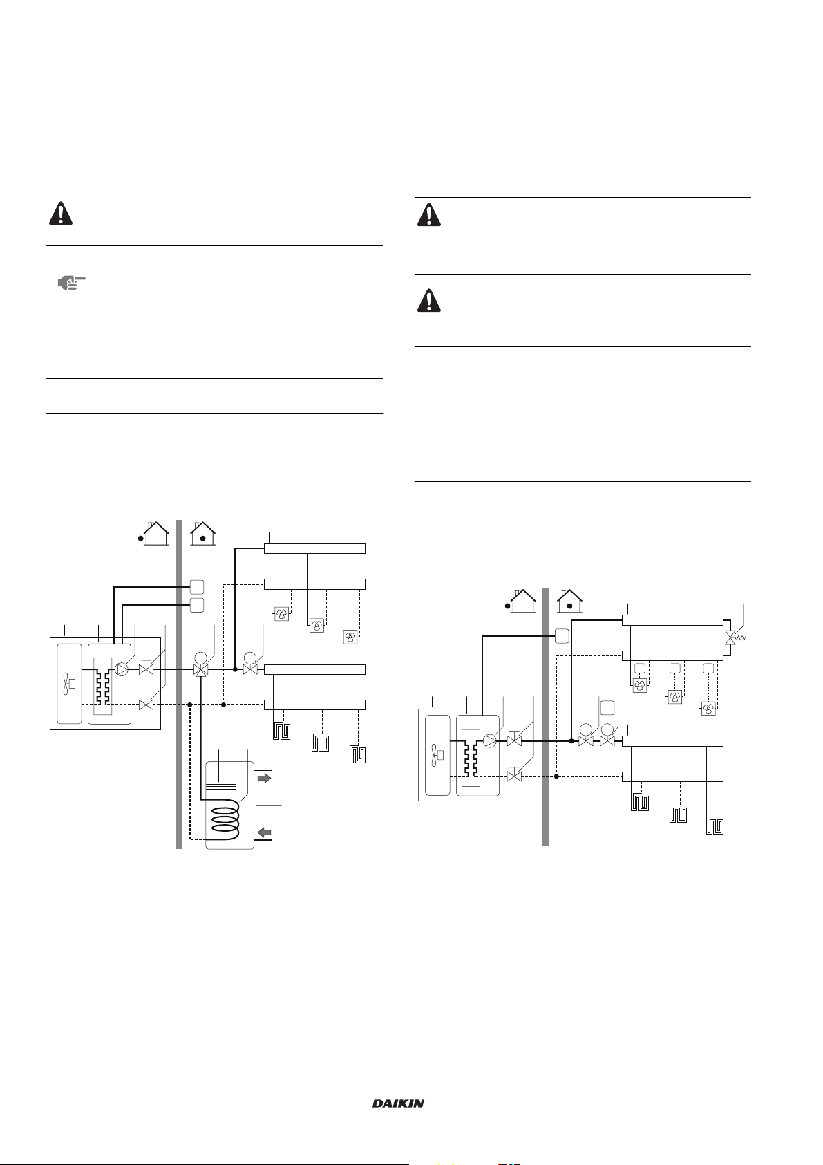
Application 3
Space cooling and heating application with a room thermostat
suitable for cooling/heating changeover connected to the unit.
Heating is provided through floor heating loops and fan coil units.
Cooling is provided through the fan coil units only.
Domestic hot water is provided through the domestic hot water tank
which is connected to the unit.
5
I
T
4321
6 11
M
FCU1
FCU2
M
98
FHL1
FCU3
FHL2
FHL3
Make sure to connect the thermostat wires to the correct
terminals (see "Connection of the thermostat cable" on
page 16) and to configure the DIP switch toggle switches
correctly (see "Room thermostat installation configuration"
on page 19).
Wiring of the 2-way valve (11) is different for a NC (normal
closed) valve and a NO (normal open) valve! Make sure to
connect to the correct terminal numbers as detailed on the
wiring diagram.
The ON/OFF setting of the heating/cooling operation is done by the
room thermostat and cannot be done by the user interface.
Domestic water heating
Domestic water heating is as described under "Application 2" on
page 6.
Application 4
Space cooling and heating application without a room thermostat
connected to the unit, but with a heating only room thermostat
controlling the floor heating and a cooling/heating thermostat
controlling the fan coil units. Heating is provided through floor heating
loops and fan coil units. Cooling is provided through the fan coil units
only.
5
I
T4 T5 T6
4321 12
11
FCU1
T
M
M
FCU2
5
FCU3
7
10
1 Unit 10 Domestic hot water tank
2 Heat exchanger 11 Motorised 2-way valve
3 Pump
4 Shut-off valve FCU1..3 Fan coil unit (field supply)
5 Collector (field supply) FHL1..3 Floor heating loop
6 Motorised 3-way valve
8 Booster heater
9 Heat exchanger coil
Installation manual
(field supply)
(field supply)
T Room thermostat with
cooling/heating switch
(field supply)
I User interface
7
FHL1
FHL2
FHL3
1 Unit 12 Motorised 2-way valve for
2 Heat exchanger
3 Pump FCU1..3 Fan coil unit with
4 Shut-off valve
5 Collector (field supply) FHL1..3 Floor heating loop (field
7 By-pass valve (field
supply) T Heating only room
11 Motorised 2-way valve
to shut off the floor
heating loops during
cooling operation (field
supply)
T4..6 Individual room
Unit for air to water heat pump system
activation of the room
thermostat (field supply)
thermostat (field supply)
supply)
thermostat (field supply)
thermostat for fan coil
heated/cooled room (field
supply)
I User interface
E(D/B)(H/L)Q011~016AA6V3+W1
4PW51121-1C
Pump operation
With no thermostat connected to the unit (1), the pump (3) can be
configured to operate either as long as the unit is on, or until the
required water temperature is reached.
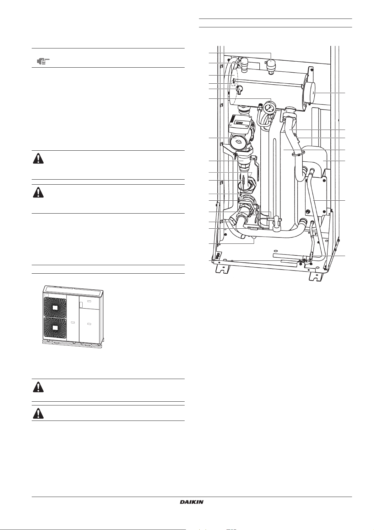
Main components
Hydraulic compartment (door 3)
NOTE
Space heating and cooling
According to the season, the customer will select cooling or heating
through the user interface.
The unit (1) will operate in cooling mode or heating mode to achieve
the target leaving water temperature.
With the unit in heating mode, the 2-way valve (11) is open. Hot water
is provided to both the fan coil units and the floor heating loops.
With the unit in cooling mode, the motorised 2-way valve (11) is
closed to prevent cold water running through the floor heating loops
(FHL).
The ON/OFF setting of the heating/cooling operation is done by the
user interface.
Details on pump configuration can be found under
"Pump operation configuration" on page 19.
When closing several loops in the system by remotely
controlled valves, it might be required to install a by-pass
valve (7) to avoid the flow switch safety device from being
activated. See also "Application 2" on page 6.
Wiring of the 2-way valve (11) is different for a NC (normal
closed) valve and a NO (normal open) valve! Make sure to
connect to the correct terminal numbers as detailed on the
wiring diagram.
19
16
18
17
13
15
10
14
12
1
2
2
3
5
8
3
9
8
3
4
7
OVERVIEW OF THE UNIT
Opening the unit
22
1
3
Door 1 gives acces to the compressor compartment and electrical parts
Door 2 gives acces to the electrical parts of the hydraulic compartment
Door 3 gives acces to the hydraulic compartment
Switch off all power supply — i.e. unit power supply and
backup heater and domestic hot water tank power supply
(if applicable) — before removing doors 1 and 2.
Parts inside the unit can be hot.
11
6
1. Air purge valve
Remaining air in the water circuit will be automatically removed
via the air purge valve.
2. Backup heater
The backup heater consists of an electrical heating element that
will provide additional heating capacity to the water circuit if the
heating capacity of the unit is insufficient due to low outdoor
temperatures, it also protects the external water piping from
freezing during cold periodes.
3. Temperature sensors
Four temperature sensors determine the water and refrigerant
temperature at various points in the water circuit.
4. Heat exchanger
5. Expansion vessel (10 l)
6. Refrigerant liquid connection
7. Refrigerant gas connection
8. Shut-off valves
The shut-off valves on the water inlet connection and water
outlet connection allow isolation of the unit water circuit side
from the residential water circuit side. This facilitates draining
and filter replacement of the unit.
9. Water inlet connection
10. Water outlet connection
11. Drain and fill valve
12. Water filter
The water filter removes dirt from the water to prevent damage
to the pump or blockage of the evaporator. The water filter must
be cleaned on a regular base. See "Maintenance" on page 29.
3
E(D/B)(H/L)Q011~016AA6V3+W1
Unit for air to water heat pump system
4PW51121-1C
Installation manual
8
13. Manometer
O
>
3T
>
t >
t >
The manometer allows readout of the water pressure in the
water circuit.
14. Flow switch
The flow switch checks the flow in the water circuit and protects
the heat exchanger against freezing and the pump against
damage.
15. Pump
The pump circulates the water in the water circuit.
16. Backup heater vessel
The backup heater heats the water in the backup heater vessel.
17. Backup heater thermal protector
The backup heater is equipped with a thermal protector. The
thermal protector is activated when the temperature becomes
too high.
18. Backup heater thermal fuse
The backup heater is equipped with a thermal fuse. The thermal
fuse is blown when the temperature becomes too high (higher
than the backup heater thermal protector temperature).
19. Pressure relief valve
The pressure relief valve prevents excessive water pressure in
the water circuit by opening at 3 bar and discharging some
water.
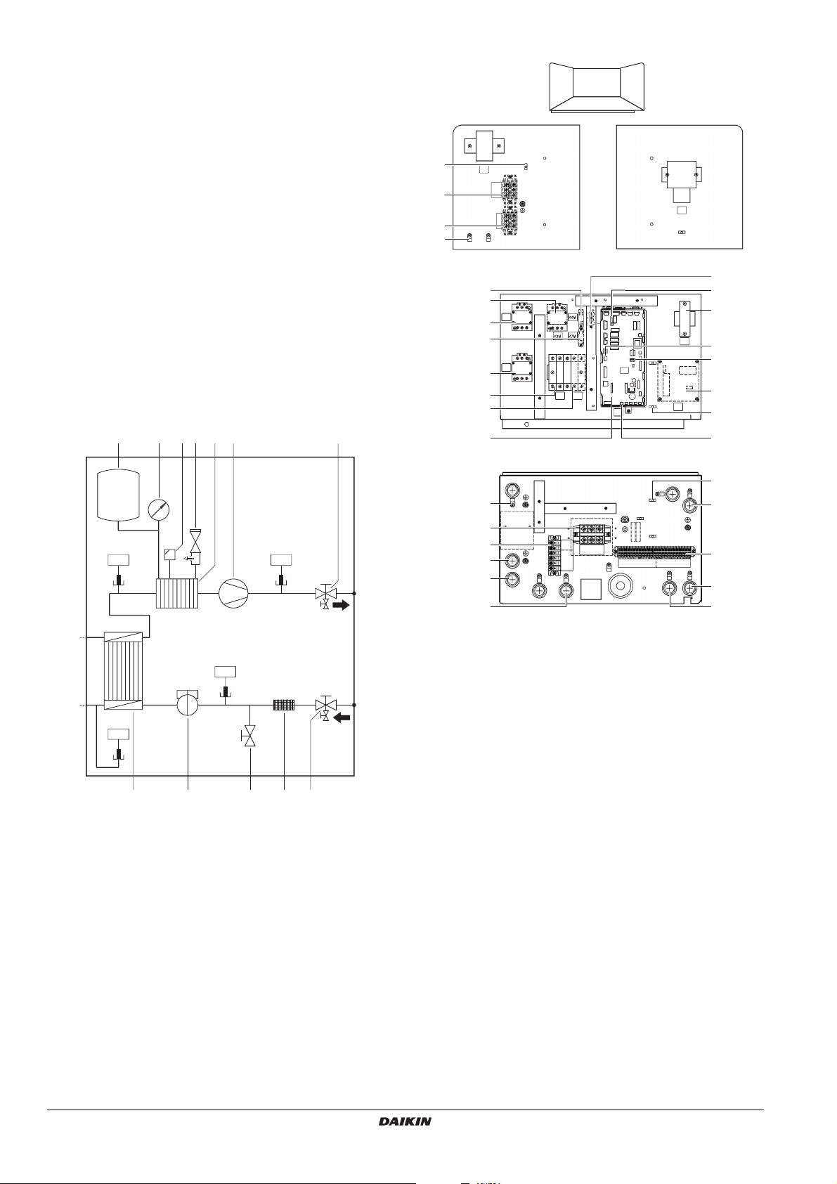
Functional diagram of hydraulic compartment (door 3)
12 6 7
34 5
Switch box main components (door 2)
ABDC
AC
8
S1T
15
18
X4M
X3M
B
3
K5M
1
on
SS2
off
on
K1M
1
5
F1B F2B
4
2
SS1
A11P
9
9
8
E5H
14 FU2
10 FU1
16
TR1
12 X13A
11 SS2
17
A4P
8
13 X9A
t
R1
t
1289 1011
1 Expansion vessel 8 Heat exchanger
2 Manometer 9 Flow switch
3 Air purge valve 10 Drain/fill valve
4 Pressure relief valve 11 Filter
5 Backup heater vessel
with backup heater
6 Pump R11T
7 Shut-off valve water
outlet
12 Shut-off valve water inlet with
drain valve
R12T
Temperature sensors
R13T
R14T
D
8
8
6
7
19
X10M
X5M
X2M
20
23
1. Backup heater contactors K1M and K5M
2. Main PCB
The main PCB (Printed Circuit Board) controls the functioning of
the unit.
3. Booster heater contactor K3M (only for installations with
domestic hot water tank)
4. Booster heater circuit breaker F2B (only for installations with
domestic hot water tank)
The circuit breaker protects the booster heater in the domestic
hot
water tank against overload or short circuit.
5. Backup heater circuit breaker F1B
The circuit breaker protects the backup heater electrical circuit
against overload or short circuit.
6. Ter minal blocks
The terminal blocks allow easy connection of field wiring.
7. Ter minal block for backup heater capacity limitation.
8. Cable tie mountings
The cable tie mountings allow to fix the field wiring with cable
ties to the switch box to ensure strain relief.
9. Ter minal blocks X3M, X4M (only for installations with domestic
hot water tank)
10. PCB fuse FU1
11. DIP switch SS2
The DIP switch SS2 provides 4 toggle switches to configure
certain installation parameters. See "DIP switch settings
overview" on page 19.
12. X13A socket
The X13A socket receives the K3M connector (only for
installations with domestic hot water tank).
24
6
22
21
Installation manual
9
E(D/B)(H/L)Q011~016AA6V3+W1
Unit for air to water heat pump system
4PW51121-1C
 Loading...