

Daikin EDEHS06A6, EDEHB06A6, EDEHS10A6, EDEHB10A6, EDEHS12A6 Installation Manual
...
INSTALLATION MANUAL
Installation manual
Electric heater kit
English
Installationsanleitung
Bausatz elektrisches Heizgerät
Deutsch
Manuel d'installation
Chauffage électrique
Français
Manual de instalación
Kit de calefactor eléctrico
Español
Manuale d'installazione
Kit riscaldatore elettrico
Italiano
EDEH04A6
EDEHS06A6
EDEHB06A6
EDEHS10A6
EDEHB10A6
EDEHS12A6
EDEHB12A6
EDEHS18A6
EDEHB18A6
Electric heater kit
CF_IM_EDEH(S)(B)A6.fm Page 1 Friday, April 7, 2006 9:12 AM

341 120
217
290
A 120269 A
329
216
290269
257
21
3
4
FWD04
FWD06
FWD08
FWD10
676
886
1096
1096
A
FWD12
FWD16
FWD18
1096
1306
1306
A
1
2
3 4
A
D
C
B
F
E
1 2
3
4
2-1
2-2
2-3 2-4
FL_IM_EDEH(S)(B)A6.fm Page 1 Friday, April 7, 2006 11:22 AM
EDEH04A6
EDEHS06A6 EDEHB06A6
EDEHS10A6 EDEHB10A6
EDEHS12A6 EDEHB12A6
EDEHS18A6 EDEHB18A6
Electric heater kit
Installation manual
Read this manual attentively before starting up the unit. Do
not throw it away. Keep it in your files for future reference.
Improper installation or attachment of equipment or
accessories could result in electric chock, short-circuit,
leaks, fire or other damage to the equipment. Be sure only
to use accessories made by Daikin which are specifically
designed for the use with the equipment and have them
installed by a professional.
If unsure of installation procedures or use, always contact
your Daikin dealer for advice and information.
All field wiring and components must be installed by a
licensed electrician and must comply with relevant local
and national regulations.
BEFORE INSTALLATION
Installation and maintenance should be carried out by technical
personnel qualified for this type of machine, in compliance with
current safety regulations.
When receiving the kit please check its state, verifying if any damage
occurred during transport.
Identify model and version of the electrical heater series from the
indications stated on the carton package.
The EDEH heating element must be combined with the
ECFWER6 controller + eventual EPIA6 or EPIMSA6.
CHARACTERISTICS
Supplied to supplement conventional hot water heating (e.g. fan coil
units served by a heat pump) or users who wish to employ electric
heating. The optional EDEH (electric heater kit) elements can be
used on all FWD thermal ventilating units.
The EDEH option is available in following versions:
Electric
Unit
FWD04 EDEH04 2.0 8.7 230 1 50
FWD06
FWD08
FWD10
FWD12
FWD16
FWD18
heater
EDEHS06 3.0 4.3 400 3 50
EDEHB06 6.0 8.7 400 3 50
EDEHS10 4.5 6.5 400 3 50
EDEHB10 9.0 13.0 400 3 50
EDEHS12 4.5 6.5 400 3 50
EDEHB12 9.0 13.0 400 3 50
EDEHS18 9.0 13.0 400 3 50
EDEHB18 12.0 17.3 400 3 50
Daikin will not be liable for any faults or damage caused by
improper use of the EDEH module and/or for
consequences of selecting an inadequate controller.
Electrical input Current rating Power supply
(kW) (A) (V) (f) (Hz)
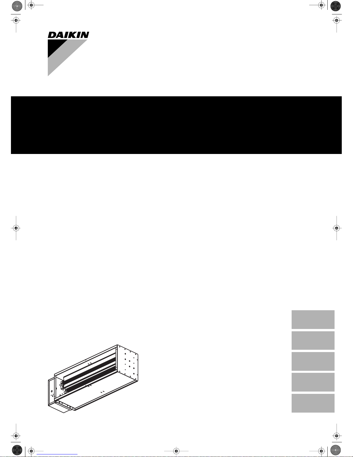
The kit shown in figure 1 consists of:
■ Electric heater assembly made of:
A finned heating elements made of aluminium, complete with
supporting brackets for fastening them to the load bearing
structure of the electric module, which is built from thick
galvanised sheet metal, duly insulated and provided with an
electric control panel for housing the power relays and wire
terminals. In conformity with electric safety directives, the module
is equipped with automatic reset safety devices (one for each
heating element) and one manual-reset safety device.
B an automatic-reset safety thermostat mounted on the heating
element, which switches it off should overheating occur as a
result of irregular operating conditions or a fault in the fan motor
unit;
C a manual-reset safety thermostat, mounted on the load bearing
structure, which switches off the heating element in the event of a
simultaneous failure of all automatic-reset safety thermostats.
NOTE
When the manual reset safety thermostat has tripped,
it can be reset as follows: (See figure 1)
1. unscrew the black cap inside the electric box
2. press the white button to reset the manual-reset safety
thermostat
3. re-install the black cap.
Sensor position of the manual reset safety thermostat
Even if the electric heater is not used in the standard
configuration, the sensor of the manual-reset safety
thermostat always needs to be positioned in the top part of
the electric heater. This means that for some applications,
the sensor will need to be re-positioned. See figure 2.
■ Standard (horizontal installation). (See figure 2-1)
Electric box of electric heater is at the same side of
the standard water connections of the unit. No need to
reposition the capillary bulb.
■ Non standard (horizontal installation)
Electric box of electric heater is at the opposite side of
the standard water connections of the unit.
Reposition the capillary bulb according to figure 2-2.
■ Non standard (vertical installation)
Reposition the capillary bulb on the top of the
automatic-reset safety thermostat according to
figure 2-3 and figure 2-4.
If more than 1 heating element, always select the top one
looking in the airflow direction.
If the capillary bulb needs to be repositioned, take care to
fasten it securely with the provided clamps using the holes
foreseen for this purpose.
D an electric box incorporating the power contactors, connection
terminals and manual-reset thermostat;
E L-shaped brackets and screws for fastening the module to the
unit outlet,
F sensor of the manual-reset safety thermostat.
EDEH04+EDEHS+B06~18A6
Electric heater kit
4PW17563-1A
Installation manual
1
INSTALLATION
Important! Before obtaining access to terminals, all power
circuits must be interrupted.
Controller
Always use the ECFWER6 controller. This controller incorporates all
necessary functions for managing the thermal ventilating unit, the
heating elements (and the on-off valves on the water side, where
present).
The EDEH electric module can only be installed on the air
outlet of the unit.
The overall dimensions are shown in figure 3.
Installing the kit
It is recommended to install the EDEH module on the thermal
ventilating unit before installing the unit in place.
1 Place the thermal ventilating unit in an upright position. Fasten
the L-shaped brackets on the two short sides of the air outlet,
using the 4 holes provided (2 per side) and self-tapping screws
(supplied in the kit).
2 After applying the 2 L-shaped brackets, which serve both as a
guide and support for the EDEH module, you can install the
module itself; make sure that the L-shaped brackets are both
positioned inside the rectangular outlet.
3 Apply the supplied self-tapping screws as shown in figure 4: the
screws on the short sides act on the L-shaped brackets, while on
the two long sides holes are provided for fastening the module
directly to the outlet of the thermal ventilating unit.
NOTE
The electric module has holes like those on the unit air
intake, on the extremity turned toward the air outflow
ducts. This allows you to attach field supplied
accessories to the unit.
Always use heat-resistant couplings if you wish to install
vibration-damping couplings.
Wiring
After fastening the electric module to the thermal ventilating unit, you
can position the latter in its final installation site and proceed with the
wiring. Refer to the manual of the ECFWER6 controller.
Each thermal-ventilating unit requires a switch (IL) on the feeder line
with a distance of at least 3 mm between the opening contacts, and a
suitable safety fuse (F).
1 Open the electric box by loosening the 4 self-tapping screws on
the front of the cover.
2 Connect the electric wires, using the wire clamps provided, both
for the power supply line and the wire to the controller on the
wall.
The minimum gauges of the power cables will depend on the
electrical inputs specified in the table in paragraph "Characteristics"
on page 1, in compliance with current regulations.
The ECFWER6 controller guarantees the complete safety of
the EDEH module, thanks to the post-ventilation function,
which keeps the fan running for 2 minutes after the heating
elements have been switched off. This feature serves to
prevent dangerous overheating which may be caused by the
thermal inertia of the heating elements themselves.
Selecting the location of the controller
The ECFWER6 controller must be installed on a wall in an easily
accessible position allowing the user to set the functions while
ensuring an accurate reading of the ambient temperature.
Therefore, avoid:
■ positions directly exposed to sunlight;
■ positions exposed to direct currents of warm or cold air;
■ placing obstacles (drapes or furniture) that prevent an accurate
temperature reading;
■ constant presence of steam;
■ covering the controller or building it into the wall.
Always check the position of the capillary bulb of the
manual reset safety thermostat. See the note "Sensor
position of the manual reset safety thermostat" on page 1.
MAINTENANCE
To guarantee the efficiency of a thermal ventilating unit fit with a
supplementary EDEH heating element module, comply with the
following directions:
■ keep the air filter clean;
■ do not pour liquids inside the unit;
■ make absolutely sure you do not obstruct the air outlet or inlet of
the unit.
OPERATION
Refer to the manual of the ECFWER6 controller.
Installation manual
2
EDEH04+EDEHS+B06~18A6
Electric heater kit
4PW17563-1A
EDEH04+EDEHS+B06~18A6
Bausatz elektrisches Heizgerät
4PW17563-1A
Installationsanleitung
1
VOR DER INSTALLATION
Die Installation und Wartung sollte von technischem Personal
durchgeführt werden, das für diese Art der Maschine qualifiziert ist,
in Übereinstimmung mit den aktuellen Sicherheitsbestimmungen.
Prüfen Sie den Zustand des Bausatzes bei Erhalt, stellen Sie fest ob
irgendwelche Beschädigungen während des Transports aufgetreten
sind.
Vergleichen Sie die Angaben auf der Verpackungseinheit mit dem
Modell und der Version der elektrischen Heizgerätebaureihe.
EIGENSCHAFTEN
Ausgeliefert, um herkömmliche Heißwasserheizung zu ergänzen
(z.B. Ventilator-Konvektoren die mittels einer Heizpumpe betrieben
werden). Die optionellen Elemente EDEH (elektrischer HeizgeräteBausatz) können an allen FWD Thermolüftungseinheiten verwendet
werden.
Die Option EDEH ist in folgenden Versionen erhältlich:
Der Bausatz der in Abbildung 1 abgebildet ist, besteht aus:
■ Baugruppe elektrisches Heizgerät hergestellt aus:
A gerippten Heizelementen, hergestellt aus Aluminium, zusammen
mit Haltebügeln zur Befestigung an das Tragegestell der elektrischen Komponente, welche aus stark galvanisiertem Blech
hergestellt, ordnungsgemäß isoliert und mit einem elektrischen
Bedienpult zur Unterbringung von Leistungsrelais und
Anschlussklemmen, ausgestattet sind. In Übereinstimmung mit
den elektrischen Sicherheitsvorschriften, ist die Komponente mit
automatischen Rückstellsicherheitsvorrichtungen (eines für jedes
Heizelement) und einer manuellen Rückstellsicherheitsvorrichtung ausgestattet.
B einem automatischen Rückstellsicherheitsthermostat, montiert
am Heizelement, das ihn ausschaltet sollte Überhitzung als Folge
eines unvorschriftsmäßigen Betriebszustands oder einer Störung
in der Ventilatormotoreinheit eintreten.
C einem manuellen Rückstellsicherheitsthermostat, montiert auf
dem Tragegestell, welches das Heizelement im Falle eines
gleichzeitigen Ausfalls aller automatischen Rückstellsicherheitsthermostate abschaltet.
D ein Elektrokasten, der die Netzkontaktgeber, Anschlussklemmen
und den manuellen Rückstellthermostat enthält;
E L-förmige Halterungen und Schrauben zur Befestigung der
Komponente am Einheitsauslass,
F Sensor des manuellen Rückstellsicherheitsthermostats.
EDEH04A6
EDEHS06A6 EDEHB06A6
EDEHS10A6 EDEHB10A6
EDEHS12A6 EDEHB12A6
EDEHS18A6 EDEHB18A6
Bausatz elektrisches Heizgerät
Installationsanleitung
Lesen Sie diese Anleitung aufmerksam durch, bevor Sie
die Einheit in Betrieb nehmen. Werfen Sie sie nicht weg.
Bewahren Sie sie so auf, so dass sie auch später noch
darin nachschlagen können.
Unsachgemäße Installation oder Sicherung der Einheit
oder der Zubehörteile kann zu elektrischem Schlag, Kurzschluss, Auslaufen von Flüssigkeit, Brand oder anderen
Schäden führen. Achten Sie darauf, nur von Daikin
hergestellte Zubehörteile zu verwenden, die spezifisch für
den Gebrauch mit der Ausrüstung konstruiert wurden und
lassen sie diese nur von einem Fachmann installieren.
Sollten Fragen zum Installationsverfahren oder zur
Inbetriebnahme auftreten, wenden Sie sich bitte an Ihren
Daikin-Händler. Von ihm erhalten Sie die notwendigen
Ratschläge und Informationen.
Sämtliche bauseitigen Verdrahtungen und Bauteile
müssen von einem zugelassenen Elektriker installiert
werden und den entsprechenden örtlichen und staatlichen
Vorschriften entsprechen.
Das Heizelement EDEH muss mit dem Regler ECFWER6
+ gegebenfalls EPIA6 oder EPIMSA6.
Gerät
Elektrisches
Heizgerät
Elektrischer
Eingang
Nennstromstärke Stromversorgung
(kW) (A) (V) (f) (Hz)
FWD04 EDEH04 2,0 8,7 230 1 50
FWD06
EDEHS06 3,0 4,3 400 3 50
EDEHB06 6,0 8,7 400 3 50
FWD08
FWD10
EDEHS10 4,5 6,5 400 3 50
EDEHB10 9,0 13,0 400 3 50
FWD12
EDEHS12 4,5 6,5 400 3 50
EDEHB12 9,0 13,0 400 3 50
FWD16
FWD18
EDEHS18 9,0 13,0 400 3 50
EDEHB18 12,0 17,3 400 3 50
Daikin haftet nicht für irgendwelche Störungen oder
Beschädigungen, die durch unsachgemäße Verwendung
der Bauelemente EDEH und/oder für Konsequenzen bei
der Auswahl eines unzulänglichen Reglers verursacht
werden.
HINWEIS
Wenn der manuelle Rückstellsicherheitsthermostat
ausgelöst hat, kann er wie folgt zurückgestellt werden:
(Siehe Abbildung 1)
1. Schrauben Sie die schwarze Kappe innen am
Elektrokasten ab,
2. betätigen Sie die weiße Taste, um den manuellen
Rückstellsicherheitsthermostat zurückzustellen,
3. montieren Sie die schwarze Kappe wieder.
Sensorstellung des manuellen Rückstellsicherheitsthermostats
Selbst wenn das elektrische Heizgerät nicht in der
Standardkonfiguration verwendet wird, muss der Sensor
des manuellen Rückstellsicherheitsthermostats immer im
oberen Teil des elektrischen Heizgerätes positioniert
werden. Das heißt, dass der Sensor für einige
Anwendungen erneut positioniert werden muss. Siehe
auch Abbildung 2.
■ Standard (horizontale Installation). (Siehe
Abbildung 2-1)
Der Elektrokasten des elektrischen Heizgerätes ist
auf der gleichen Seite der Standardwasseranschlüsse
der Einheit. Es ist nicht notwendig die Kapillarglühlampe erneut zu positionieren.
■ Nichtstandard (horizontale Installation).
Der Elektrokasten des elektrischen Heizgerätes ist
auf der gegenüberliegenden Seite der Standardwasseranschlüsse der Einheit.
Positionieren Sie die Kapillarglühlampe erneut gemäß
Abbildung 2-2.
■ Nichtstandard (vertikale Installation).
Positionieren Sie die Kapillarglühlampe oben am
automatischen Rückstellsicherheitsthermostat gemäß
Abbildung 2-3 und Abbildung 2-4.
Bei mehr als einem Heizelement, wählen Sie immer das
obere, das sich in Richtung Luftdurchfluss befindet.
Wenn die Kapillarglühlampe erneut positioniert werden
muss, achten Sie darauf, sie mit den vorgesehenen
Klemmen mithilfe der vorgesehenen Bohrungen sicher zu
befestigen.
IM_DE_EDEH(S)(B)A6.fm Page 1 Tuesday, April 4, 2006 6:34 PM
 Loading...