

Daikin DP13GM3604541A, DP13GM3007041A, DP13GM3607041A, DP13GM3609041A, DP13GM4207041A Technical Manual
...
TECHNICAL MANUTECHNICAL MANU
TECHNICAL MANU
TECHNICAL MANUTECHNICAL MANU
DP 13 SEER
R-410A Single Phase
Package Gas Unit s
• Refer to Service Manual RSD6312004 for installation, operation, and troubleshooting information.
• All safety information must be followed as provided in the Service Manual.
• Refer to the appropriate Parts Catalog for part number information.
• Models listed on page 3.
ALAL
AL
ALAL
This manual is to be used by qualified, professionally trained HVAC technicians only. Daikin does
not assume any responsibility for property damage or personal injury due to improper service
procedures or services performed by an unqualified person.
Copyright © 2013 - 2014
RTD6312004r1
March 2014
PRODUCT IDENTIFICATION
The model and manufacturing number are used for positive identification of component parts used in manufacturing.
Please use these numbers when requesting service or parts information.
D P 13 G M 24 070 4 1 A A
Brand Engineering
D - D aik in Minor revision
Product Type Engineering
P - Packaged Major revision
Voltage
SEER 1 - 208/230 V single phase 60 Hz
13 - 13 SEER 2 - 220/240 V single phase 50 Hz
14 - Up to 14 SEER 3 - 208/230 V three phase 60 Hz
15 - Up to 15 SEER 4 - 460 V three phas e 60 H z
5 - 380/415 V three phase 50 Hz
Unit Type
G - Gas/Electric R efrigerant
D - Dual Fuel 4 - R-410A
C onfiguration Nominal Heat Input
M - Multi-position 045 45 MBTU/H 115 115 MBTU /H
H - Horizonta l 070 70 MBTU/H 140 140 MBTU/H
090 90 MBTU/H
WARNING
WARNING
Tonnage Nominal
24 - 2 ton 42 - 3.5 ton
30 - 2.5 ton 48 - 4.0 ton
36 - 3 ton 60 - 5 ton
HIGH VOLTAGE!
Disconnect ALL power before servicing or installing this unit. Multiple power
sources may be present. Failure to do so may cause property damage, personal
injury or death.
WARNING
WARNING
vice procedures. If you install or perform service on this
unit, you assume responsibility for any personal injury or
property damage which may result. Many jurisdictions
require a license to install or service heating and air
conditioning equipment.
Daikin will not be responsible for
any injury or property damage arising from improper service or ser-
2
WARNING
WARNING
fied by the Air-Conditioning, Heating, and Refrigeration
Institute (AHRI) may use this information. Attempting to
install or repair this unit without such background may
result in product damage, personal injury, or death.
ONLY individuals meeting (at a
minimum) the requirements of an
"Entry Level Technician" as speci-

PRODUCT IDENTIFICATION
The model and manufacturing number are used for positive identification of component parts used in manufacturing.
Please use these numbers when requesting service or parts information.
DP13GM2404541A*
DP13GM2407041A*
DP13GM3004541A*
DP13GM3007041A*
DP13GM3604541A*
DP13GM3607041A*
DP13GM3609041A*
DP13GM4207041A*
DP13GM4209041A*
DP13GM4807041A*
DP13GM4809041A*
DP13GM4811541A*
DP13GM6009041A*
DP13GM6011541A*
DP13GM6014041A*
WARNING
WARNING
WARNING
WARNING
erty damage, personal injury, reduced unit performance
and/or hazardous conditions may result from the use of
such non-approved devices.
The United States Environmental Protection Agency (“EPA”) has issued various regulations regarding the introduction and disposal of refrigerants introduced into this unit. Failure to follow these
regulations may harm the environment and can lead to the imposition of substantial fines. These
regulations may vary by jurisdiction. Should questions arise, contact your local EPA office.
Do not connect or use any device
that is not design certified by Daikin
for use with this unit. Serious prop-
WARNING
WARNING
do not store combustible materials or use gasoline or
other flammable liquids or vapors in the vicinity of this
appliance.
To prevent the risk of property
damage, personal injury, or death,
3

PRODUCT DESIGN
DP13GM Package Gas Units are designed for outdoor installations only in either residential or light commercial applications and are available in 2 through 5 ton sizes. They are
designed for 208/230 volt single phase applications. (DP13GM
3, 4 and 5 ton models are also available for 230V 3 phase
applications. See Technical Manual RTD6312005.)
The connecting ductwork (Supply and Return) can be connected for either horizontal or vertical airflow. In the vertical
application, a matching Roof Curb is recommended.
A return air filter must be installed behind the return air grille(s)
or provision must be made for a filter in an accessible location within the return air duct. The minimum filter area should
not be less than those sizes listed in the Specification Section. Under no circumstances should the unit be operated
without return air filters.
A 3/4" pipe is provided for removal of condensate water from
the indoor coil. (Do not reduce the drain line size).
NOTE: Tighten drain to a maximum torque of 10 in-lbs.
Refrigerant flow control is achieved by use of restrictor orifices. DP13GM units use the FasTest Access Fitting System which consists of a saddle that is either soldered to the
suction and liquid lines or is fastened with a locking nut to
the access fitting box (core) and then screwed into the saddle.
NOTE: The core must not be removed from the saddle
until the refrigerant charge has been removed. Failure
to do so could result in property damage or personal
injury.
The single phase units use permanent split capacitors (PSC)
design compressors. Starting components are therefore not
required. A low MFD run capacitor assists the compressor
to start and remains in the circuit during operation.
The outdoor fan and indoor blower motors are single phase
permanent split capacitor type motors. DP13GM48***41**
and DP13GM60***41** models are equipped with EEM indoor blower motors. EEM motors are constant torque motors with very low power consumption and are energized by a
24V signal from the ignition control. The EEM features an
integrated control module.
Air for condensing (cooling cycle) is drawn through the outdoor coil by a propeller fan, and is discharged vertically out
the top of the unit. The outdoor coil is designed for .0 static.
No additional restriction (ductwork) shall be applied.
Conditioned air is drawn through the filter(s), field installed,
across the coil and back into the conditioned space by the
indoor blower.
Some models of the DP13GM series package units use the
Compliant Scroll compressor, there are a number of design
characteristics which are different from the traditional reciprocating compressor.
- Due to their design Scroll compressors are inherently more
tolerant of liquid refrigerant. NOTE: Even though the compressor section of a Scroll compressor is more tolerant
of liquid refrigerant, continued floodback or flooded start
conditions may wash oil from the bearing surfaces causing premature bearing failure.
- These Scroll compressors use "POE" or polyester oil
which is NOT compatible with mineral oil based lubricants
like 3GS. "POE" oil must be used if additional oil is
required.
- Compliant scroll compressors perform "quiet" shutdowns
that allow the compressor to restart immediately without
the need for a time delay. This compressor will restart
even if the system has not equalized.
- Operating pressures and amp draws may differ from standard reciprocating compressors. This information may be
found in the "Cooling Performance Data" section.
4
PRODUCT DESIGN
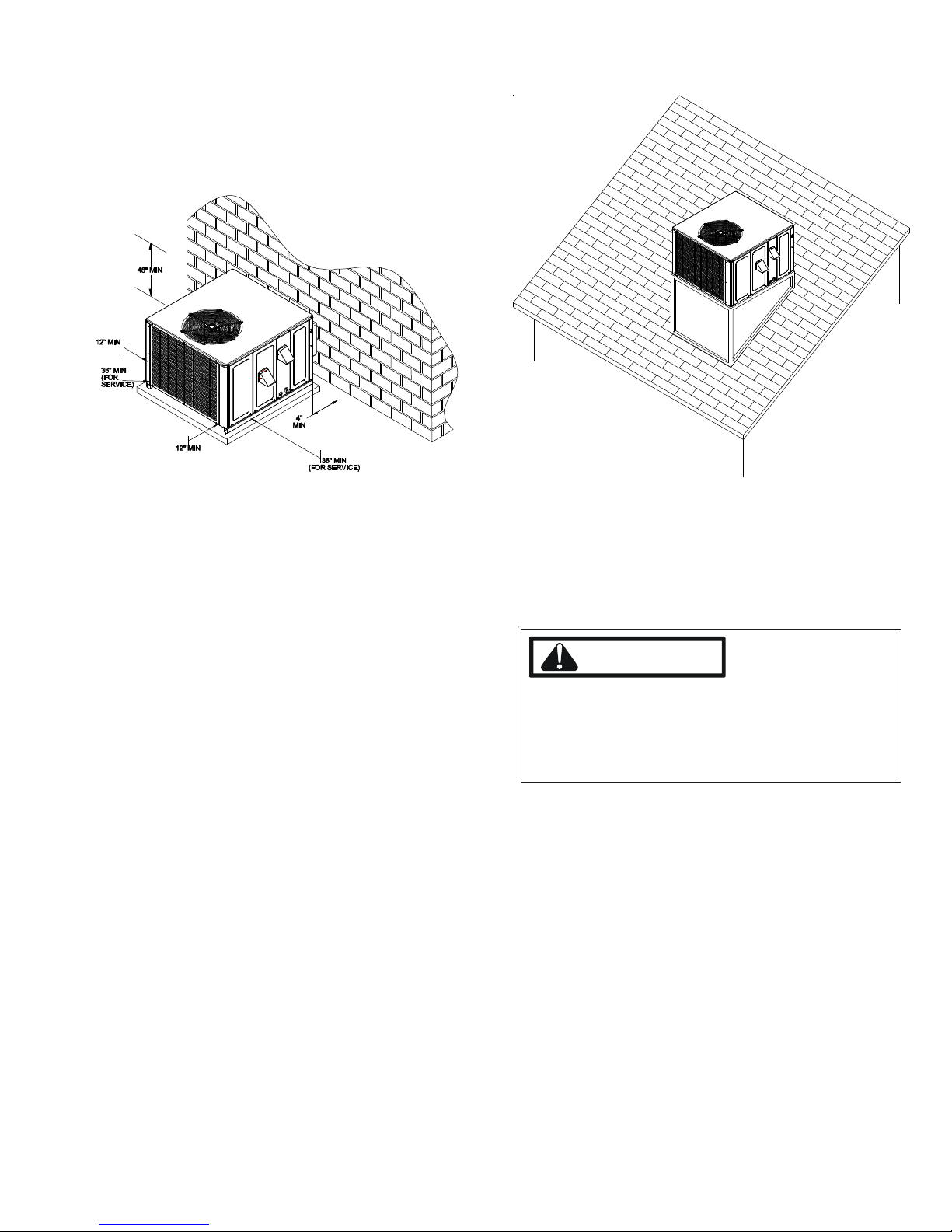
Location and Clearances
NOTE: To ensure proper condensate drainage, unit must be
installed in a level position.
Outside Slab Installation
NOTE: Roof overhang should be no more than 36" and pro-
vision made to deflect the warm discharge air out from the
overhang. Minimum clearances are required to avoid air
recirculation and keep the unit operating at peak efficiency.
Rooftop Installation
NOTE: To ensure proper condensate drainage, unit must
be installed in a level position.
WARNING
TO
PREVENT POSSIBLE PROPERTY DAMAGE, THE UNIT
SHOULD REMAIN IN AN UPRIGHT POSITION DURING ALL
RIGGING AND MOVING OPERATIONS
LIFTING AND MOVING IF A CRANE IS USED, PLACE THE UNIT
IN AN ADEQUATE CABLE SLING
IMPORTANT: If using bottom discharge with roof curb, duct-
work should be attached to the curb prior to installing the
unit.
Refer to Roof Curb Installation Instructions for proper curb
installation. Curbing must be installed in compliance with
the National Roofing Contractors Association Manual.
.
. TO
FACILITATE
5
PRODUCT DESIGN
High Altitude Derate - U.S. Installations Only (Optional)
The gas/electric units naturally derate with altitude. High
Altitude Derate kit may be installed if desired.
IMPORTANT NOTE: The gas/electric units naturally derate
with altitude. Do not attempt to increase the firing rate by
changing orifices or increasing the manifold pressure. This
can cause poor combustion and equipment failure. At all
altitudes, the manifold pressure must be within 0.3 inches
W.C. of that listed on the nameplate for the fuel used. At all
altitudes and with either fuel, the air temperature rise must
be within the range listed on the unit nameplate. Refer to
the Installation Manual provided with the LP kit for conversion
from natural gas to propane gas and for altitude adjustments.
When this package unit is installed at high altitude, the appropriate High Altitude orifice kit may be installed. As altitude increases, there is a natural reduction in the density of
both the gas fuel and combustion air. This kit will provide the
proper design certified input rate within the specified altitude
range. High altitude kits are not approved for use in Canada.
For installations above 2,000 feet, use kit HA-02. The HA-02
kit is used for both Natural and LP gas at high altitudes.
Use LPT-03 propane conversion kit for propane conversions
at altitudes below 2000 feet. Natural gas installations below
2000 feet do not require a kit.
For propane conversion above 2000 feet, high altitude kit
HA-02 is required in addition to the LPT-03 propane conversion kit.
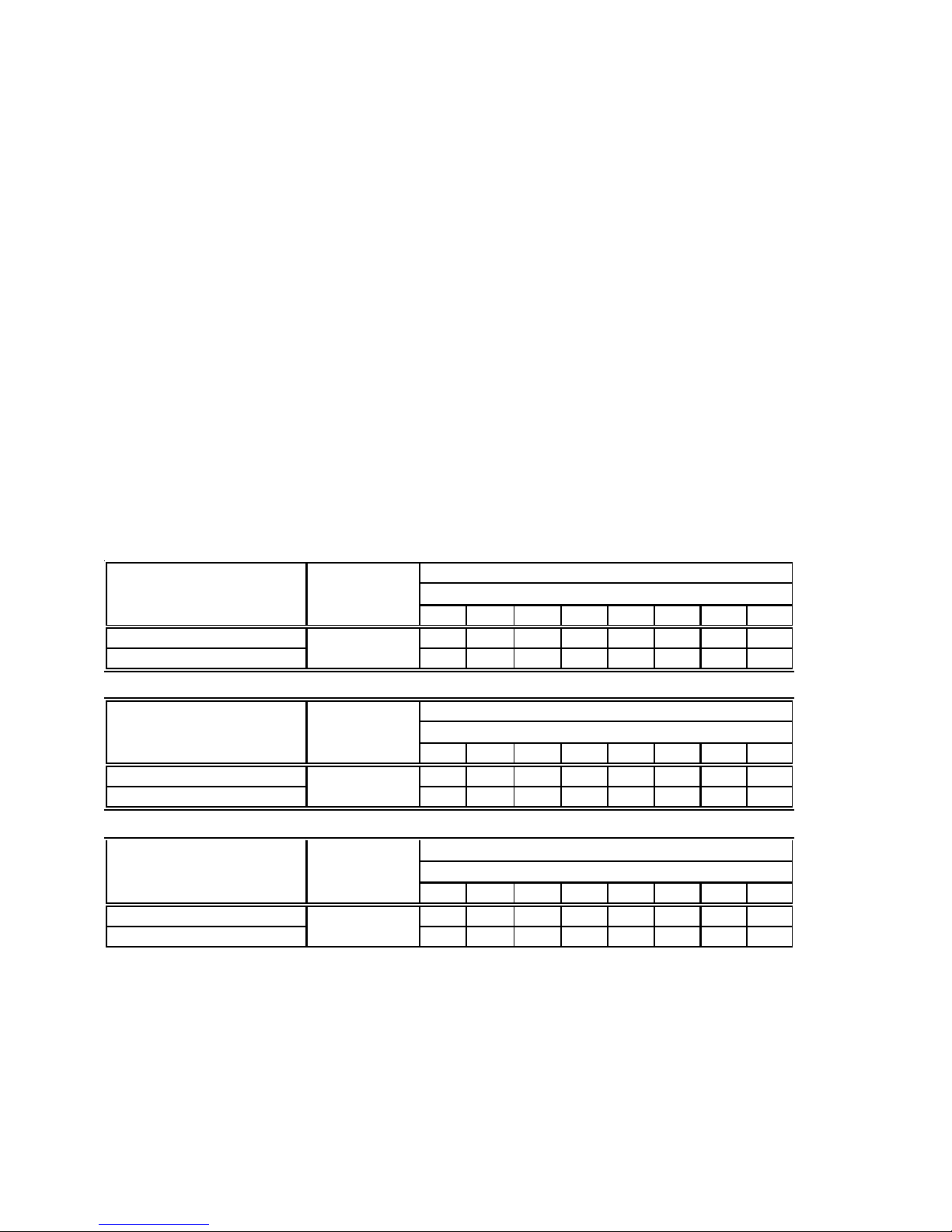
NATURAL GAS AND LP GAS INSTALLATIONS AT ALTITUDES > 2000 FT
INPUT/BURNER
U.S. BUR NER OR IFICE 45/55 47/55 47/56 - 47/56 48/57 48/58 49/58
CA NADA BURNE R O R I FIC E 45/55 - - 4 8 /5 7 - - - -
INPUT/BURNER
U.S. BUR NER OR IFICE 44/55 44/55 45/56 - 45/56 46/57 47/58 47/58
CA NADA BURNE R O R I FIC E 44/55 - - 4 7 /5 7 - - - -
INPUT/BURNER
U.S. BUR NER OR IFICE 43/55 43/55 44/56 - 44/56 44/56 45/57 45/57
CA NADA BURNE R O R I FIC E 43/55 - - 4 6 /5 7 - - - -
HI G H AL TI TUDE
KI T
HA-02
HI G H AL TI TUDE
KI T
HA-02
HI G H AL TI TUDE
KI T
HA-02
2000 3000 4000 4500 5000 6000 7000 8000
2000 3000 4000 4500 5000 6000 7000 8000
2000 3000 4000 4500 5000 6000 7000 8000
20,000 BTUH NAT/20,000 BTUH /L.P.
ELEVATION ABOVE SEA-LEVEL (FEET)
22,500 BTUH NAT/20,000 BTUH /L.P.
ELEVATION ABOVE SEA-LEVEL (FEET)
25,000 BTUH NAT/20,000 BTUH /L.P.
ELEVATION ABOVE SEA-LEVEL (FEET)
6
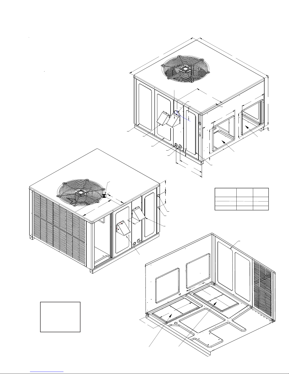
PRODUCT DIMENSIONS
UNIT DIMENSIONS
SUCTION/LIQUID PRESSURE PORTS
BEHIND COMPRESSOR ACCESS PANEL
COMBUSTION AIR INTAKE
HEAT EXCHANGE ACCESS PANEL
CONDE NSATE DRAIN CONNECTION
F
O
R
Y
E
T
T
I
N
V
E
A
C
R
G
20
24
47
GAS SUPPLY ENTRANCE
3/4" NPT FEMALE
FLUE E X HAUST
HOOD
FLUE EXHAUST
C
4 3/4
16 1/8
19 1/8
7 5/16
7 7/8
POW ER W IRE ENTRA NCE
CONTROL WIRE ENTRANCE
51
18 7/16
1 3/8
5 1/2
16
7 15/16
B
(INCHES)
SUPPLY
3
EVAPORATOR/CONTROL PANEL ACCESS PANEL
DIMENSION
B
MEDIUM
16
RETURN
A3240
B1618
C9 1/214
A
2 3/4
LARGE
MEDIUM CHASSIS
DP13GM24, 30, 36
LARGE CHASSIS
DP13GM42, 48, 60
5 1/4
COMBUSTION
AIR INTAKE
SUPPLY
EXHAUST FLUE HOOD
BLOWER ACCESS PANEL
11
5 3/4
22
11
RETURN
22
7

ACCESSORIES
DP13[C,G,H]M, DP14DM and DP15[G,H]M
Part Number Description
CDK36 3 Ton Concentric Duct Kit
CDK36515 3 Ton Flush Mount Concentric Duct Kit w/ F ilt er
CDK3 65 30 3 Ton St ep D own Co nc en tric Duct Kit
CDK3 65 35 3 Ton St ep D own Co nc en tric Duct Kit w/ Filter
CDK4 872 4 - 6 Ton Concen tric Du c t Kit
CDK4872515 4 - 6 Ton Flush Mount Concentric Duct Kit w/ F ilt er
CDK4 87 2530 4 - 6 Ton St e p Do wn Co ncentri c D uc t Kit
CDK4 87 2535 4 - 6 Ton St e p Do wn Co ncentri c D uc t Kit w / Filt er
D14CRBPGCHMA 14" Curb Daikin-M Series Package Unit A ll Chassis
DDN25FDPG CH MM Manual 25 % M-S er i es F r esh Air Damper D ownflow Application, Medium Chassis
DDN25FDPG CH ML Manual 25 % M-S er i es F r esh Air Damper D ownflow Application, La rg e C ha ssis
DDN25MFDPGCHMM Motorized 25% M-Series Fresh Air Damper Downflow Application, Medium Chassis
DDN25MFDPG CHML Motorized 25% M- Ser ies Fresh A ir Downflow A pplication, Large Chassis
DDNE CNJ P GM M Downflow Jade E c on omizer Da ik in M-Series Ga s Package Unit , M ed ium Cha ssis
DDNE CNJ P GM L Downflow Jade E c on omizer Da ik in M-Series Ga s Package Unit , Large Ch assis
DDNIFRPG A Downflow Internal Filter Rack for Daikin M- Series Gas Package Unit
DHZ25FDPGCHMS Manual 25% M-Series Fresh Air Damper Horizont al Application, Small Chassis
DHZ 2 5FDPG CH MM Manual 25 % M-S e ri es F r e sh Air Damper H or i zont a l Appl ic ation, Medium Chassis
DHZ25FDPGCHML Manual 25% M-Series Fresh Air Damper Horizont al Application, Large Chassis
DHZ25M F DPG CHMS Motoriz ed 25% M-Ser ies Fresh A ir Damper Horiz ontal Application, Small Chassis
DHZ25M F DPG CHMM Motorized 25% M- Ser ies Fresh A ir Damper Horiz ont al Application, Medium Chassis
DHZ25M F DPG CHML Motorized 25% M -Ser ies Fresh A ir Damper Horizontal Application, Large Chassis
DHZECNJPGCHM Horiz ontal Jade Economizer M-Ser ies Package Unit A ll F uels, Medium Chassis H-Series All Chassis
DHZECNJPGCHL Horiz ontal Jade Economizer M-Ser ies Package Unit All Fuels, Large Chassis
DPHFRA External Horizontal Filter Rack for Daikin M- and H-Series Package Units
HA-02 High Altitude Kit
LPT-03 Pr op an e Co nversion K it
SQRPG101/102
SQRPG103
SQRPGH101/102
SQRPGH103
Square to Round Adapter for M-Series Package Unit w/ 16" Round Downflow A pplication, Medium
Chassis
Square to Round Adapter for M-Series Package Unit w/ 18" Round Downflow A pplication, Large
Chassis
Square to Round Adapter f or M-Series Package Unit w/ 16" Round Horizontal Application, Small and
Medium Chassis
Square to Round Adapter f or M-Series Package Unit w/ 18" Round Horizontal Application, Large
Chassis
8
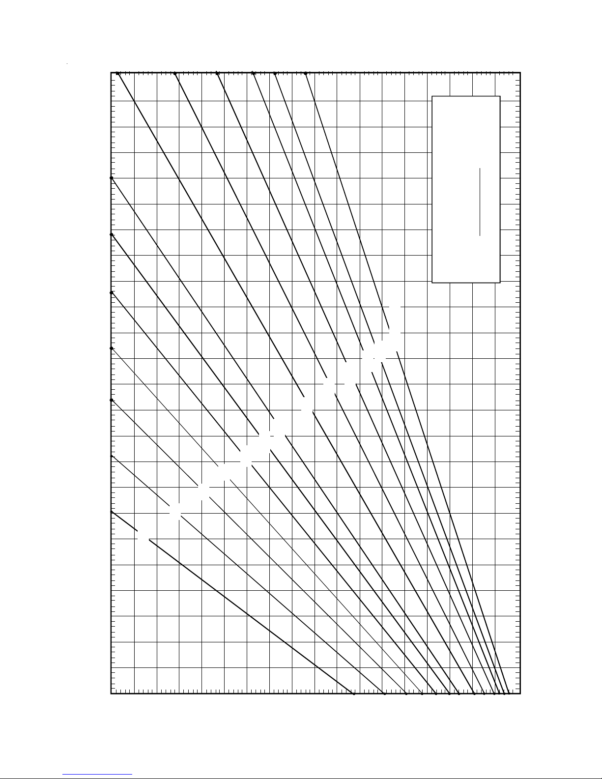
BLOWER PERFORMANCE DATA
÷ CFM
130 140 150
800
900
FORMULAS
BTU OUTPUT = CFM x 1. 08 x RISE
1.08
BTU OUTPUT
RISE =
100
2400 CFM
2200
2000
1800
1600
1400
1200
1100
1000
OUTPUT BTU/HR x 1000
BTU OUTPUT vs TEMPERATURE RISE CHART
600 CFM
100
700
90
80
70
60
50
30 40 50 60 70 80 90 110 120
40
30
20
10
TEMPERATURE RISE
9

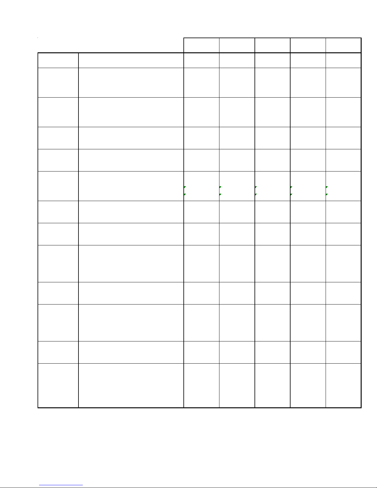
P ACKAGE GAS SPECIFICATIONS
DP13GM24045
41A*
COOLING
CAPACITY
HEATING
CAPACITY
UNIT
ELECTRICAL
SPECIFICATION
HEATING
SECTION
COMPRESSOR
CONDENSER
FAN M OT OR
CONDENSER
FAN
CONDENSER
COIL
EVAPORATOR
BLOWER
MOTOR
EVAPORATOR
BLOWER
EVAPORATOR
COIL
HEATING
LIMITS
GENERAL
INFORMATION
COOLING CAPACITY, BTUH 23,6 00 23,600 28,600 28,600 35,000
SEER / E E R 13. 0 / 11.0 13.0 / 11. 0 13.0 / 11.0 13.0 / 11.0 13. 0 / 11.0
HEA TING INPUT BTUH (U.S. & CA NA DIA N) 46 , 0 00 69,000 46,000 69, 000 46,000
HEA TING OUTPUT BTUH (U.S. & CANADIAN) 36, 7 00 55,000 36,700 55, 000 36,700
AFUE (%) 8080808080
TEMP E RA TURE RISE (°F ) 30 - 60 35 - 65 30 - 60 35 - 65 30 - 60
VOLTAG E (NA M E PLATE) 208/230 208/2 30 208/ 230 208/230 208/230
UNIT AMPS (TOTAL) 16. 1 16.1 17.5 17.5 21.2
MINIMUM CIRCUIT AM P ACITY 19. 5 19. 5 20. 9 20.9 25.4
MA XIMUM OV ERCURRE NT PROTECTION
NUMBER OF BURNERS 23232
ORIFICE SIZE NATURAL 4343434343
ORIFICE SIZE LP 55 55 55 55 55
TYPE Scroll Sc roll Scroll Scroll Scroll
RATED LOA D A M P S 13.5 13.5 14.1 14.1 16.7
LOCKE D RO TOR AMP S 58. 3 58.3 73.0 73.0 79.0
HORSEPOWER 1/6 1/6 1/4 1/4 1/4
RPM 830 830 1100 1100 830
FULL LOA D A M P S 1.1 1 . 1 1.4 1.4 1.5
LOCKED ROTOR AMPS 3.0 3.0 2.9 2.9 3.0
BLADE DIAMETER (INCHES) 22 22 22 22 22
NUMBER OF BLADES 33333
CFM 2400 2400 2700 2700 2400
FACE AREA - SQ. FT. 12.31 12.3 1 12.31 12. 31 8. 77
NUMBER OF ROWS 11112
FINS PER INCH 24 24 24 24 27
HORSEPOWER - NO. OF SPEEDS 1/4 - 3 1/4 - 3 1/3 - 3 1/3 - 3 1/3 - 3
FULL LOA D A M P S 1.5 1 . 5 1.9 1.9 3.1
LOCKED ROTOR AMPS 2.2 2.2 3.1 3.1 4.1
MOTOR SPEED TAP - COOLING Med Med Med Med High
RPM 952 952 1,015 1,015 910
DIAME TER X WIDTH (INCHES) 1 0” x 8” 10” x 8” 10” x 8” 10” x 8” 10” x 9”
RATED S CFM COOLING 800 800 1000 1000 1250
MAX EXTERNAL STATIC PRESS (" w.c.) 0.5 0.5 0.5 0.5 0.5
FACE AREA - SQ. FT. 4.33 4.33 4.33 4.33 4.33
NUMBER OF ROWS 33444
FINS PER INCH 14 14 14 14 14
FILTER SIZE - SQ. FT.
DRAIN S IZE (INCHES) 3/4 3/4 3/ 4 3/4 3/4
PRIMA RY LIMIT SE TTING (°F) 150 150 150 150 160
AUXILIARY LIMIT SETTING (°F) 150 150 150 150 150
ROLLOUT LIMIT SETTING (°F) 3 50 350 350 350 350
PISTON EXPANS ION DE V ICE Orific e (. 057) Ori fic e (.057) Orifice (.062) Orifice (.062) Orifi c e (. 0 68)
REF RIGERANT CHARG E R-4 10A (Oz.) 75 75 78 7 8 70
POWER SUPPLY ENTRANCE SIZE (INCHES) 1 1/8 1 1/8 1 1/8 1 1/8 1 1/8
LOW VOLTAGE ENTRANCE SIZE (INCHES) 7/8 7/8 7/8 7/8 7/8
SHIPPING WE IGHT LBS . 420 425 421 425 470
OPERATING WE IGHT LBS . 396 397 397 399 449
(2)
(3)
30 30 35 35 40
2.7 2.7 3.3 3.3 4.2
DP13GM24070
DP13GM[24-36]***41A*
41A*
DP13GM30045
41A*
DP13GM30070
41A*
(1 ) Units installed in Canada are certifed only to 4500 feet.
(2) Calculated external filter size based on air velocity of 300 ft/min. and applies to disposable filters only.
(3 ) Maximum Overcurrent Protection Device: MUST use Time Delay Fuse or HACR type Circuit Breaker of the same size as noted.
IMPORTANT: While this data is presented as a guide, it is important to electrically connect the unit and properly size wires and fuses/
circuit breakers in accordance with the National Electrical Code and/or all local codes.
DP13GM36045
41A*
10
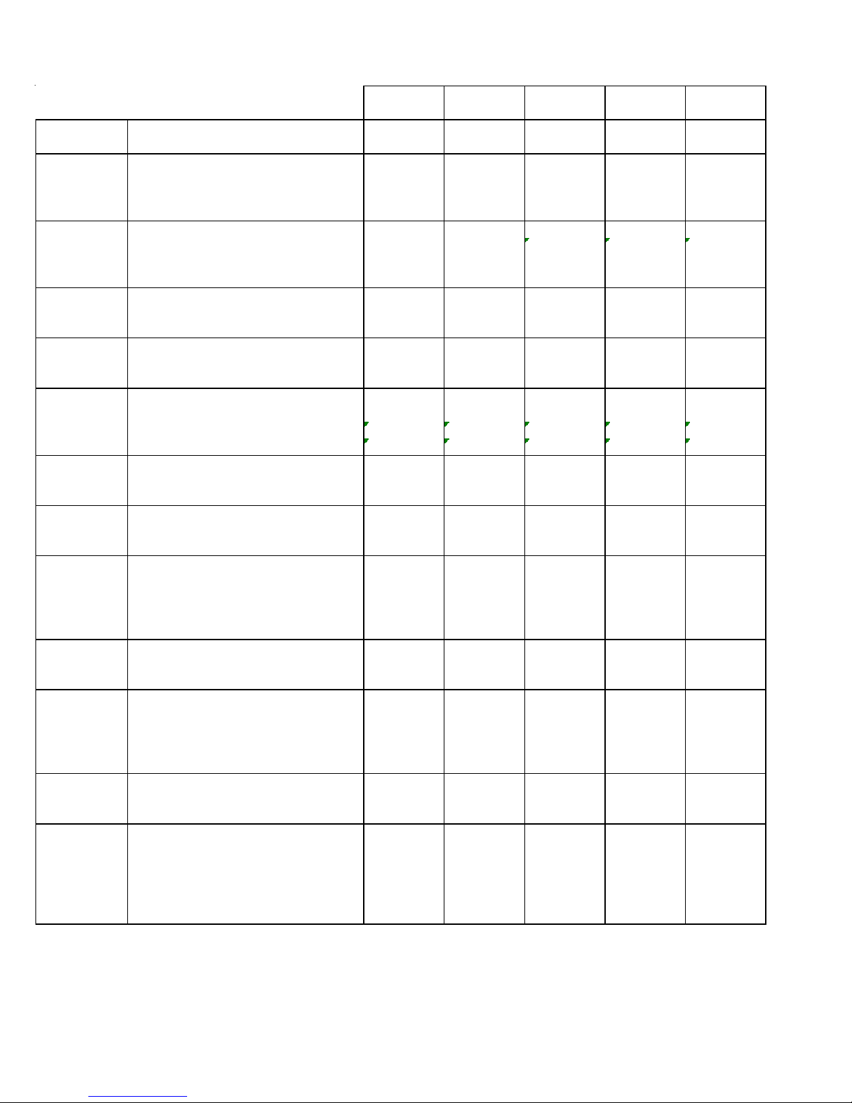
P ACKAGE GAS SPECIFICATIONS
DP13GM36070
41A*
COOLING COOLING CAPACITY, BTUH 35,000 35,000 40,500 40,500 46,000
CAPACITY SEER / EE R 13.0 / 11.0 13.0 / 11.0 13.0 / 11.0 13.0 / 11.0 13.0 / 11.0
HEA TING INP UT B TUH (U. S. & C A N A D IA N) 69,000 92,000 6 9,000 92,000 69,000
HEATING HEA TING OUTPUT B TUH (U.S. & CA NA DIAN) 55, 000 73, 600 55, 000 73, 600 55,0 00
CAPACITY AFUE (%) 8080808080
TEMPERATURE RISE (°F) 35 - 65 45 - 75 35 - 65 45 - 75 35 - 65
UNIT VOLTAGE (NAMEPLATE) 208/230 208/230 208/230 208/230 208/230
ELECTRICAL UNIT AMPS (TOTAL) 21.2 21.2 22.3 22.3 27.1
SPECIFICATION MINIMUM CIRCUIT AMPACITY 25.4 25.4 26.8 26.8 32.1
MAXIMUM OVE RCURRENT PROTECTION 40 40 40 40 50
HEATING NUMBER OF BURNERS 34343
SECTION ORIFICE SIZE NATURAL 4343434343
ORIFICE S IZE LP 55 55 55 55 55
COMPRESSOR TYPE Scroll Scroll Scroll Scroll Scroll
RATED LOAD AMPS 16.7 16.7 17.9 17.9 19.9
LOCKED ROTOR AMPS 79.0 79.0 112.0 112. 0 109. 0
CONDE NSE R HORSEPOWER 1/4 1/4 1/4 1/4 1/4
FAN MOTOR RPM 830 830 1100 1100 1100
FULL LOAD AMPS 1.5 1.5 1.4 1.4 1.4
LOCKED ROTOR AMPS 3.0 3.0 2. 9 2.9 2.9
CONDENSER BLADE DIAMETER (INCHES) 22 22 22 22 22
FAN NUMBER OF BLADES 33333
CFM 2400 2400 3500 3500 3500
CONDENSER FACE AREA - SQ. FT. 8.77 8.77 15.3 15.3 15.3
COIL NUMBER OF ROWS 22111
FINS PER INCH 27 2 7 24 24 24
EVAPORATOR HORSEPOWER - NO. OF SPEEDS 1/3 - 3 1/3 - 3 1/3 - 3 1/3 - 3 3/4 - 5
BLOWER FULL LOAD AMPS 3.06 3.06 3.06 3.06 5.8
MOTOR LOCKED ROTOR AMPS 4.1 4.1 4. 1 4.1 --
MOTOR SPEED TAP - COOLING High High Medium Medium T4
RPM 910 910 910 910 1050
EVAPORATOR DIAM E TE R X WIDTH (INCHE S) 10” x 9” 10” x 9” 10” x 10” 10” x 10” 11” x 10”
BLOWER RATED SCF M COOLING 1200 12 00 1300 1300 155 0
MAX EXTERNAL STATIC PRESS ("w.c.) 0.5 0.5 0.5 0.5 0.5
EVAPORATOR FACE AREA - SQ. FT. 4.33 4.33 5.67 5.67 5.67
COIL NUMBER OF ROWS 44444
FINS PER INCH 14 1 4 14 14 14
FILTER SIZE - SQ. FT.
DRA IN SIZE (I NC HES) 3/4 3 /4 3/4 3/ 4 3/ 4
HEATING PRIMARY LIMIT SETTING (°F) 160 160 170 170 170
LIMITS AUXILIARY LIMIT SETTING (°F) 150 150 150 150 150
ROLLOUT LIMIT SETTING (°F) 350 350 350 350 350
GENERAL PISTON EXPANSION DEVICE Orifice (.068) Orifice (.068) Orifice (.072) Orifice (.072) Orifice (.076)
INFORMATION REFRIGERANT CHARGE R-410A (Oz.) 7070999987
POWER SUPPLY ENTRANCE SIZE (INCHES) 1 1/8 1 1/8 1 1/8 1 1/8 1 1/8
LOW VOLTAGE ENTRANCE SIZE (INCHES) 7/8 7/8 7/8 7/8 7/8
SHIP PING W EIGHT LBS . 4 75 480 515 520 540
OPERATING WEIGHT LB S. 453 4 58 493 496 51 8
(1 ) Units installed in Canada are certifed only to 4500 feet.
(2) Calculated external filter size based on air velocity of 300 ft/min. and applies to disposable filters only.
(3 ) Maximum Overcurrent Protection Device: MUST use Time Delay Fuse or HACR type Circuit Breaker of the same size as noted.
IMPORTANT: While this data is presented as a guide, it is important to electrically connect the unit and properly size wires and fuses/
circuit breakers in accordance with the National Electrical Code and/or all local codes.
(2)
4.2 4.2 4.7 4.7 5.1
DP13GM36090
DP13GM[36-48]***41A*
41A*
DP13GM42070
41A*
DP13GM42090
41A*
DP13GM48070
41A*
11
P ACKAGE GAS SPECIFICATIONS
DP13GM48090
41A*
COOLING C OO L ING CAPA C ITY, BTUH 46, 0 00 46, 00 0 5 7 ,000 57,000 57,0 00
CAPACITY SEER / EER 13.0 / 11.0 13.0 / 11.0 13.0 / 10.75 13.0 / 10.75 13.0 / 10.75
HEATING INPUT BTUH (U.S. & CANADIAN) 92,000 115,000 92, 000 115,000 138,000
HEATING HE ATING OUTPUT BTUH (U.S. & CANADIAN) 73,600 92,000 73,600 92,000 110,400
CAPACITY AFUE (%) 8080808080
TEMPERATURE RIS E (°F) 45 - 75 45-75 45 - 75 45 - 75 45 - 75
UNIT VOLTAGE (NAMEPLATE) 208/230 208/230 208/230 208/ 230 208/ 230
ELECTRICAL UNIT AMP S (TOTAL) 27.1 27.1 35.4 35.4 35.4
SPECIFICATION MINIMUM CIRCUIT A MP ACITY 32. 1 32.1 42.0 42.0 42.0
MA XIMUM OVERCURRENT PROTECTION 50 50 60 60 60
HEATING NUMBER OF B URNERS 4 5 4 5 6
SECTION ORIFICE SIZE NATURAL 4343434343
ORIFICE SIZE LP 55 55 55 55 55
COMPRESSOR TYPE Scroll Scroll Scroll Scroll Scroll
RATED LOAD AMPS 19.9 19.9 26.4 26.4 26.4
LOCKED ROTOR AMPS 109.0 109.0 134.0 134.0 134.0
CONDENSER HORSEPOWER 1/4 1/4 1/4 1/4 1/4
FAN MOTOR RPM 11001100110011001100
FULL LOAD AMPS 1. 4 1.4 1. 4 1.4 1.4
LOCKED ROTOR AMPS 2.9 2.9 2.9 2.9 2.9
CONDENSER BLADE DIAM ETER (INCHES) 22 22 22 22 22
FAN NUMBER OF BLADES 3 3 3 3 3
CFM 35003500350035003500
CONDENSER FACE AREA - SQ. F T. 15.3 15.3 11.3 11.3 11.3
COIL NUMB E R OF ROWS 1 1 2 2 2
FINS PE R INCH 24 24 27 27 27
EVAPORATOR HOR S EPOWE R - NO. OF S P EEDS 3/4 - 5 3/4 - 5 1 - 5 1 - 5 1 - 5
BLOWER FULL LOAD AMP S 5.8 5. 8 7.6 7.6 7.6
MOTOR LOCK ED ROTOR AMPS -- -- -- -- --
MOTOR SPEED TAP - COOLING T4 T4 T4 T4 T4
RPM 10501050105010501050
EVAPORATOR DIAMETER X WIDTH (INCHES) 11” x 10” 11” x 10” 11” x 10” 11” x 10” 11” x 10”
BLOWER RATED SCFM COOLING 15501550175017501750
MAX EXTERNAL STATIC PRESS ("w.c.) 0.5 0.5 0.5 0.5 0.5
EVAPORATOR FACE AREA - SQ. FT. 5.67 5.67 5.67 5.67 5.67
COIL NUMB E R OF ROWS 4 4 4 4 4
FINS PE R INCH 14 14 14 14 14
FILTER SIZE - SQ. FT.
DRAIN SIZE (INCHES) 3/4 3/4 3/4 3/ 4 3/4
HEATING P RIMARY LIMIT SETTING (°F) 170 170 170 170 160
LIMITS AUXILIARY LIMIT SETTING (°F) 150 150 150 150 150
ROLLOUT LIMIT S E TTING (°F) 350 350 350 350 350
GENERAL PISTON EXPANSION DEVICE Orifice (.076) Orifice (.076) Orifice (.086) Orifice (.086) Orifice (.086)
INFORMATION REFRIGERANT CHARGE R-410A (Oz.) 8787919191
POW E R SUP PLY E NTRANCE SIZE (INCHES) 1 1/8 1 1/8 1 1/8 1 1/8 1 1/8
LOW VOLTAGE ENTRANCE SIZE (INCHES) 7/8 7/8 7/8 7/8 7/8
SHIPPING WEIGHT LB S . 545 550 555 560 565
OPERATING WEIGHT LB S. 523 528 533 538 543
(1 ) Units installed in Canada are certifed only to 4500 feet.
(2) Calculated external filter size based on air velocity of 300 ft/min. and applies to disposable filters only.
(3 ) Maximum Overcurrent Protection Device: MUST use Time Delay Fuse or HACR type Circuit Breaker of the same size as noted.
IMPORTANT: While this data is presented as a guide, it is important to electrically connect the unit and properly size wires and fuses/
circuit breakers in accordance with the National Electrical Code and/or all local codes.
( 2)
5.1 5.1 6.3 6.3 6.3
DP13GM48115
DP13GM[48-60]***41A*
41A*
DP13GM60090
41A*
DP13GM60115
41A*
DP13GM60140
41A*
12
 Loading...