

Daikin DM80VC, DC80VC Installation Instructions Manual

DM80VC/DC80VC
GAS FURNACE - CATEGORY 1
(T ype FSP CA TÉGORIE IV Direct
ou four á air soufflé non direct)
Installer: Affix all manuals adjacent to the unit.
These furnaces comply with requirements embodied in the American National S tandard / National Standard of Canada ANSI Z21.47·CSA-
2.3 Gas Fired Central Furnaces.
INSTALLATION INSTRUCTIONS
O
NLY PERSONNEL THAT HAVE BEEN TRAINED TO INSTALL, ADJUST, SERVICE OR
REPAIR (HEREINAFTER
MANUAL SHOULD SERVICE THE EQUIPMENT
BE RESPONSIBLE FOR ANY INJURY OR PROPERTY DAMAGE ARISING FROM
IMPROPER SERVICE OR SERVICE PROCEDURES
ASSUME RESPONSIBILITY FOR ANY INJURY OR PROPERTY DAMAGE WHICH MAY
RESULT
. IN
LICENSES TO SERVICE THE EQUIPMENT SPECIFIED IN THIS MANUAL, ONLY
LICENSED PERSONNEL SHOULD SERVICE THE EQUIPMENT
INSTALLATION, ADJUSTMENT, SERVICING OR REPAIR OF THE EQUIPMENT
SPECIFIED IN THIS MANUAL, OR ATTEMPTING TO INSTALL, ADJUST, SERVICE OR
REPAIR THE EQUIPMENT SPECIFIED IN THIS MANUAL WITHOUT PROPER
TRAINING MAY RESULT IN PRODUCT DAMAGE, PROPERTY DAMAGE, PERSONAL
INJURY OR DEATH
, “
SERVICE
”)
THE EQUIPMENT SPECIFIED IN THIS
. THE
MANUFACTURER WILL NOT
. IF
YOU SERVICE THIS UNIT, YOU
ADDITION, IN JURISDICTIONS THAT REQUIRE ONE OR MORE
. I
MPROPER
.
PROP 65 WARNING
FOR CALI FORNIA CONSUMERS
Cancer and Reproductive Harm -
www.P65Warnings.ca.gov
0140M00513-A
RECOGNIZE THIS SYMBOL AS A SAFETY PRECAUTION.
ATTENTION INSTALLING PERSONNEL
As a professional installer , you have an obligation to know the product better than the customer .
This includes all safety precautions and related items.
Prior to actual installation, thoroughly familiarize yourself with this Instruction Manual.
Pay special attention to all safety warnings. Often during installation or repair , it is possible to place yourself
in a position which is more hazardous than when the unit is in operation.
Remember, it is your responsibility to install the product safely and to know it well enough
to be able to instruct a customer in its safe use.
Safety is a matter of common sense...a matter of thinking before acting.
Most dealers have a list of specific, good safety practices...follow them.
The precautions listed in this Installation Manual are intended as supplemental to existing practices.
However, if there is a direct conflict between existing practices and the content of this manual,
the precautions listed here take precedence.
NOTE: Please contact your distributor or our website listed below for the applicable S pecification Sheet referred to in
this manual.
IOD-2012D
9/2018
Our continuing commitment to quality products may mean a change in specifications without notice.
© 2013-2016, 2017, 2018
5151 San Felipe St., Suite 500, Houston, TX 77056
www.daikinac.com

Table of Contents
SAFETY CONSIDERATIONS ........................................................................................................................................................... 4
SHIPPING INSPECTION ........................................................................................................................................................ 6
ADDITIONAL SAFETY CONSIDERATIONS ................................................................................................................................... 6
ELECTROSTATIC DISCHARGE (ESD) PRECAUTIONS ................................................................................................................... 7
TO THE INSTALLER ............................................................................................................................................................ 7
P
RODUCT DESCRIPTION ............................................................................................................................................................. 7
FEATURES ........................................................................................................................................................................ 7
PRODUCT APPLICATION .............................................................................................................................................................. 7
LOCATION REQUIREMENTS AND CONSIDERATIONS ........................................................................................................................... 10
LEARANCES AND ACCESSIBILITY ....................................................................................................................................... 10
C
INSTALLATION POSITIONS ................................................................................................................................................... 10
HORIZONT A L INSTALLATION................................................................................................................................................. 10
FURNACE SUSPENSION .................................................................................................................................................... 10
EXISTING FURNACE REMOVAL ............................................................................................................................................ 10
THERMOST AT LOCATION ..................................................................................................................................................... 10
C
OMBUSTION AND VENTILATION AIR REQUIREMENTS ...................................................................................................................... 10
EXTERIOR MASONRY CHIMNEYS .................................................................................................................................................. 13
(CA TEGORY I FURNACES ONLY).................................................................................................................................................. 13
HECKLIST SUMMARY ...................................................................................................................................................... 13
C
C
HECK 1 - PROPER CHIMNEY TERMINATION. ........................................................................................................................ 13
CHECK 2 - ANY SOLID OR LIQUID FUEL APPLIANCES VENTED INTO THIS CHIMNEY CHANNEL ....................................................... 14
CHECK 3 - CHIMNEY CROWN CONDITION. ........................................................................................................................... 14
CHECK 4 - DEBRIS IN CLEANOUT....................................................................................................................................... 14
CHECK 5 - LINER CONDITION. .......................................................................................................................................... 14
CHECK 6 - DILUTION AIR. ............................................................................................................................................... 15
CHECK 7 - COMPLETE THE INSTALLATION. ............................................................................................................................ 15
FIX 1 - LINER TERMINATION .............................................................................................................................................. 15
FIX 2 - CHANGE VENTING ARRANGEMENTS .......................................................................................................................... 15
FIX 3 - REBUILD THE CROWN ........................................................................................................................................... 16
FIX 4 - RELINING............................................................................................................................................................ 16
ELECTRICAL CONNECTIONS ....................................................................................................................................................... 16
WIRING HARNESS ........................................................................................................................................................... 17
115 VOLT LINE CONNECTIONS .......................................................................................................................................... 17
JUNCTION BOX RELOCATION ............................................................................................................................................. 17
24 VOLT THERMOSTAT WIRING .......................................................................................................................................... 18
FOSSIL FUEL APPLICATIONS.............................................................................................................................................. 18
SINGLE-STAGE HEATING THERMOSTAT APPLICATION ................................................................................................................ 18
24 VOLT DEHUMIDISTAT WIRING ........................................................................................................................................ 19
FOSSIL FUEL APPLICATIONS.............................................................................................................................................. 19
115 VOLT LINE CONNECTION OF ACCESSORIES (HUMIDIFIER AND ELECTRONIC AIR CLEANER).................................................... 19
24 VOLT HUMIDIFIER....................................................................................................................................................... 20
AUXILIARY ALARM SWITCH ............................................................................................................................................... 20
GAS SUPPLY AND PIPING .......................................................................................................................................................... 20
HIGH ALTITUDE DERATE ................................................................................................................................................... 21
PROPA N E GAS CONVERSION .............................................................................................................................................. 21
GAS PIPING CONNECTIONS ............................................................................................................................................... 21
UPFLOW INSTALLA TIONS.................................................................................................................................................... 22
COUNTERFLOW INSTALLATIONS ........................................................................................................................................... 22
GAS PIPING CHECKS ....................................................................................................................................................... 22
PROPANE GAS TANKS AND PIPING ...................................................................................................................................... 23
CIRCULATING AIR.................................................................................................................................................................... 23
CHECKING DUCT STATIC ................................................................................................................................................... 24
FILTERS - READ THIS SECTION BEFORE INSTALLING THE RETURN AIR DUCTWORK .................................................................... 24
UPRIGHT INSTALLATIONS ................................................................................................................................................... 24
HORIZONT A L INSTALLATIONS ............................................................................................................................................... 24
CIRCULATION AIR FILTERS ................................................................................................................................................ 25
START-UP PROCEDURE AND ADJUSTMENT ................................................................................................................................... 26
HEAT ANTICIPATOR SETTING ............................................................................................................................................... 26
FURNACE OPERATION ....................................................................................................................................................... 26
2

Table of Contents
FURNACE STARTUP .......................................................................................................................................................... 26
FURNACE SHUTDOWN ...................................................................................................................................................... 27
GAS SUPPLY PRESSURE MEASUREMENT .............................................................................................................................. 27
GAS MANIFOLD PRESSURE MEASUREMENT AND ADJUSTMENT .................................................................................................. 28
GAS INPUT RATE MEASUREMENT (NATURAL GAS ONLY)........................................................................................................... 30
TEMPERATURE RISE ......................................................................................................................................................... 30
CIRCULATOR BLOWER SPEEDS .......................................................................................................................................... 30
BLOWER HEAT OFF DELAY TIMINGS .................................................................................................................................... 32
OMFORTNET™ SYSTEM .......................................................................................................................................................... 32
C
O
VERVIEW ..................................................................................................................................................................... 32
AIRFLOW CONDIDERATIONS............................................................................................................................................... 33
FOSSIL FUEL APPLICATIONS.............................................................................................................................................. 33
CTK0* WIRING ............................................................................................................................................................. 33
FOUR-WIRE INDOOR AND OUTDOOR WIRING ....................................................................................................................... 33
TWO-WIRE OUTDOOR, FOUR-WIRE INDOOR WIRING ........................................................................................................... 34
COMFORTNET™ COMPATIBLE FURNACE WITH NON-COMFORTNET COMPATIBLE SINGLE-STAGE AIR CONDITIONER .............................. 34
OMFORTNET™ SYSTEM ADVANCED FEATURES ............................................................................................................................. 34
C
T
HERMOSTAT MENU ......................................................................................................................................................... 34
DIAGNOSTICS .................................................................................................................................................................. 34
NETWORK TROUBLESHOOTING ........................................................................................................................................... 36
SYSTEM TROUBLESHOOTING .............................................................................................................................................. 36
NORMAL SEQUENCE OF OPERATION ............................................................................................................................................ 36
POWER UP .................................................................................................................................................................... 36
HEATING MODE ............................................................................................................................................................... 36
COOLING MODE ............................................................................................................................................................. 38
FAN ONLY MODE ............................................................................................................................................................ 38
OPERATIONAL CHECKS ............................................................................................................................................................. 38
SAFETY CIRCUIT DESCRIPTION ................................................................................................................................................... 38
INTEGRATED CONTROL MODULE ......................................................................................................................................... 39
PRIMARY LIMIT................................................................................................................................................................ 39
AUXILIARY LIMIT ............................................................................................................................................................. 39
ROLLOUT LIMIT .............................................................................................................................................................. 39
PRESSURE SWITCHES...................................................................................................................................................... 39
FLAME SENSOR .............................................................................................................................................................. 39
TROUBLESHOOTING ................................................................................................................................................................. 39
ELECTROSTATIC DISCHARGE (ESD) PRECAUTIONS ................................................................................................................. 39
DIAGNOSTIC CHART ......................................................................................................................................................... 39
FAULT RECALL ................................................................................................................................................................ 39
FAULT CLEAR SEQUENCE: ................................................................................................................................................ 39
RESETTING FROM LOCKOUT .............................................................................................................................................. 40
MAINTENANCE ......................................................................................................................................................................... 40
ANNUAL INSPECTION ........................................................................................................................................................ 40
FILTERS ........................................................................................................................................................................ 40
FILTER MAINNTENANCE ..................................................................................................................................................... 40
FILTER REMOVAL ............................................................................................................................................................. 40
HORIZONTAL UNIT FILTER REMOVAL .................................................................................................................................... 40
MEDIA AIR FILTER OR ELECTRONIC AIR CLEANER REMOVAL ................................................................................................... 40
BURNERS ...................................................................................................................................................................... 40
INDUCED DRAFT AND CIRCULATOR BLOWERS ....................................................................................................................... 41
FLAME SENSOR (QUALIFIED SERVICER ONLY)...................................................................................................................... 41
FLUE PASSAGES (QUALIFIED SERVICER ONLY)..................................................................................................................... 41
BEFORE LEA VING AN INSTALLATION.............................................................................................................................................. 41
REPAIR AND REPLACEMENT PARTS .............................................................................................................................................. 41
TROUBLESHOOTING CHART ................................................................................................................................................ 42 - 46
ST ATUS CODES ....................................................................................................................................................................... 47
AIR FLOW DATA ...................................................................................................................................................................... 48
DIP SWITCHES ....................................................................................................................................................................... 49
WIRING DIAGRAM DM80VC/DC80VC ............................................................................................................................................ 50
3
S
AFETY
C
ONSIDERA TIONS
WARNING
Adhere to the following warnings and cautions when installing,
adjusting, altering, servicing, or operating the furnace. T o ensure proper installation and operation, thoroughly read this
manual for specifics pertaining to the installation and application of this product.
This furnace is manufactured for use with natural gas. It may
be field converted to operate on L.P . gas by using the appropriate L.P . conversion kit listed in the PROPANE GAS/HIGH AL-
TITUDE INSTALLATIONS section of this manual
Install this furnace only in a location and position as specified
in LOCATION REQUIREMENTS & CONSIDERATIONS sec-
tion and INST ALLATION POSITIONS section of this manual.
Provide adequate combustion and ventilation air to the furnace
as specified in COMBUSTION & VENTILATION AIR RE-
QUIREMENTS section of this manual.
Combustion products must be discharged to the outdoors.
Connect this furnace to an approved vent system only , as specified in Category 1 Venting section of this manual.
Never test for gas leaks with an open flame. Use a commercially available soap solution made specifically for the detection of leaks to check all connections, as specified in GAS
SUPPLY AND PIPING section of this manual.
FIRE OR EXPLOSION HAZARD
Failure to follow the safety warnings exactly could result
in serious injury, death or property damage.
Never test for gas leaks with an open flame.
Use a commercially available soap solution made
specifically for the detection of leaks to check all
connections. A fire or explosion may result causing
property damage, personal injury or loss of life.
AVERTISSEMENT
RISQUE D'INCENDIE OU D'EXPLOSION
Si les consignes de sécurité ne sont pas suivies à la lettre,
cela peut entraîner la mort, de graves blessures ou des
dommages matériels.
Ne jamais vérifier la présence de fuites de gaz au moyen
d'une flamme nue. Vérifier tous les raccords en utilisant
une solution savonneuse commerciale conçue
spécialement pour la détection de fuites. Un incendie ou
une explosion risque de se produire, ce qui peut entraîner
la mort, des blessures ou des dommages matériels.
Always install a furnace to operate within the furnace’s intended
temperature-rise range with a duct system which has external
static pressure within the allowable range, as specified on the
furnace rating plate and OPERATIONAL CHECKS section of
these instructions.
When a furnace is installed so that supply ducts carry air circulated by the furnace to areas outside the space containing
the furnace, the return air shall also be handled by duct(s)
sealed to the furnace casing and terminating outside the space
containing the furnace.
A gas-fired furnace for installation in a residential garage must
be installed as specified in the LOCA TION REQUIREMENTS
AND CONSIDERA TIONS section of this manual.
This furnace may be used as a construction site heater only if
certain conditions are met. These conditions are listed in the
PRODUCT APPLICATION section of this manual.
WARNING
TO
PREVENT PERSONAL INJURY OR DEATH DUE TO IMPROPER
INSTALLATION, ADJUSTMENT, ALTERATION, SERVICE OR MAINTENANCE
REFER TO THIS MANUAL
INFORMATION, CONSU LT A QUALIFIED INSTALLER, SERVICER AGENCY OR
THE GAS SUPPLIER
. FOR
ADDITIONAL ASSISTANCE OR
.
WARNING
IF
THE INFORMATION IN THESE INSTRUCTIONS IS NOT FOLLOWED
EXACTLY, A FIRE OR EXPLOSION MAY RESULT CAUSING PROPERTY
DAMAGE
,
PERSONAL INJURY OR LOSS OF LIFE
DO
NOT STORE OR USE GASOLINE OR OTHER FLAMMABLE VAPORS AND
LIQUIDS IN THE VICINITY OF THIS OR ANY OTHER APPLIANCE
.
.
WHAT TO DO IF YOU SMELL GAS:
D
O NOT TRY TO LIGHT ANY APPLIANCE
D
O NOT TOUCH ANY ELECTRICAL SWITCH; DO NOT USE ANY PHONE
IN YOUR BUILDING
I
MMEDIATELY CALL YOUR GAS SUPPLIER FROM A NEIGHBOR’S
PHONE
. F
OLLOW THE GAS SUPPLIER’S INSTRUCTIONS
I
F YOU CANNOT REACH YOUR GAS SUPPLIER, CALL THE FIRE
DEPARTMENT
I
NSTALLATION AND SERVICE MUST BE PERFORMED BY A QUALIFIED
INSTALLER, SERVICE AGENCY OR THE GAS SUPPLIER
.
.
.
.
.
,
4
WARNING
H
EATING UNIT SHOULD NOT BE UTILIZED WITHOUT REASONABLE
ROUTINE, INSPECTION, MAINTENANCE AND SUPERVISION
BUILDING IN WHICH ANY SUCH DEVICE IS LOCATED WILL BE VACANT
CARE SHOULD BE TAKEN THAT SUCH DEVICE IS ROUTINELY INSPECTED
MAINTAINED AND MONITORED. IN THE EVENT THAT THE BUILDING
MAYBE EXPOSED TO FREEZING TEMPERATURES AND WILL BE VACANT
ALL WATER-BEARING PIPES SHOULD BE DRAINED, THE BUILDING SHOULD
BE PROPERLY WINTERIZED, AND THE WATER SOURCE CLOSED. IN THE
EVENT THAT THE BUILDING MAY BE EXPOSED TO FREEZING
TEMPERATURES AND WILL BE VACANT, ANY HYDRONIC COIL UNITS
SHOULD BE DRAINED AS WELL AND, IN SUCH CASE, ALTERNATIVE HEAT
SOURCES SHOULD BE UTILIZED
.
. IF
THE
,
,
,
,
WARNING
TO
PREVENT POSSIBLE PROPERTY DAMAGE, PERSONAL INJURY OR
DEATH DUE TO ELECTRICAL SHOCK, THE FURNACE MUST BE LOCATED TO
PROTECT THE ELECTRICAL COMPONENTS FROM WATER
.
5
Advertencia especial para la instalación de calentadores ó manejadoras
de aire en áreas cerradas com o estacionamient os ó cuartos de ser vicio.
RISQUE D'EMPOISONNEMENT AU
MONOXYDE DE CARBONE
Las emis iones de mon óxido de carbono pueden circular a través
del aparat o cuando s e opera e n cualquier mod o.
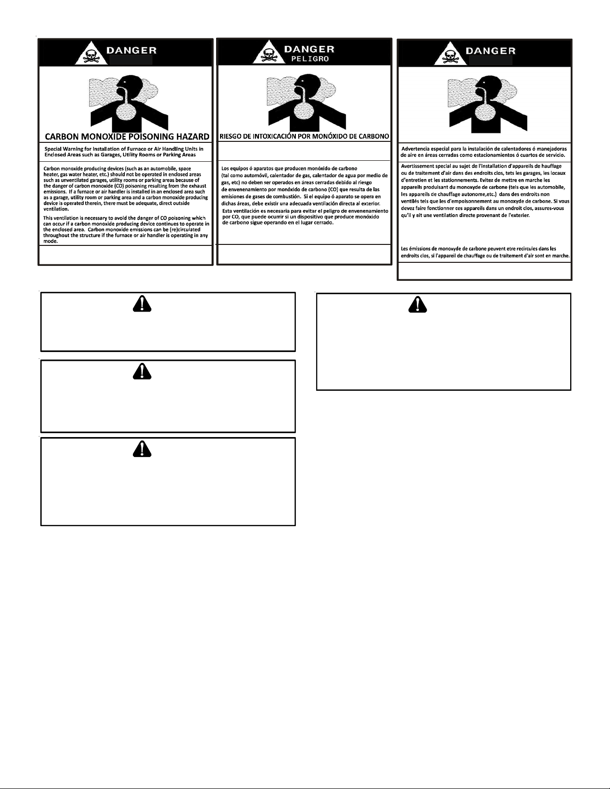
CO can cause serious illness including perm anent brain
damage or death.
B10259-216
El monóx ido de car bono puede causa r enferme dades severas
como daño cerebral p ermanente ó m uerte.
WARN ING
S
HOULD OVERHEATING OCCUR OR THE GAS SUPPLY FAIL TO SHUT OFF
TURN OFF THE MANUAL GAS SHUTOFF VALVE EXTERNAL TO THE
FURNACE BEFORE TURNING OFF THE ELECTRICAL SUPPLY
.
,
WARN ING
P
OSSIBLE PROPERTY DAMAGE, PERSONAL INJURY OR DEATH DUE TO
FIRE, EXPLOSION, SMOKE, SOOT, CONDENSATIO N, ELECTRICAL SHOCK
OR CARBO N MONOXIDE MAY RESULT FROM IMPROPER INSTALLATION
REPAIR OPERATION, OR MAINTENANCE OF THIS PRODUCT
.
,
WARN ING
TO
PREVENT PERSONAL INJURY OR DEATH DUE TO IMPROPER
INSTALLATION, ADJUSTMENT, ALTERATIO N, SERVICE OR MAINTENANCE
REFER TO THIS MANUAL
INFORMATION, CONSULT A QUALIFIED INSTALLER, SERVICER AGENCY OR
THE GAS SUPPLIER
. FOR
ADDITIONAL ASSISTANCE OR
.
Cette ventilation est nécessaire pour éviter le danger d'intoxication
au CO po uvant surveni r si un appare il produisant du monoxyde
de carbon e continue de fonctionne r au sein de la zone confinée.
B10259-216
TO
PREVENT PERSONAL INJURY OR DEATH DUE TO ASPHYXIATION, THIS
FURNACE MUST BE CATEGORY
ATEGORY
C
P
ROVISIONS MUST BE MADE FOR VENTING COMBUSTION PRODUCTS
OUTDOORS THROUGH A PROPER VENTING SYSTEM
FLUE PIPE COULD BE A LIMITING FACTOR IN LOCATING THE FURNACE
III
VENTING
Le monoxyde de
des
dommag es per manents au cerve au et meme la mort .
.
ADDITIONAL SAFETY CONSIDERATIONS
• This furnace is approved for Category I Venting only .
• Provisions must be made for venting combustion
products outdoors through a proper venting system.
The length of flue pipe could be a limiting factor in
locating the furnace.
,
carbone peut causer des maladies graves telles que
WARNING
I
VENTED
. DO
NOT VENT USING
. THE
LENGTH OF
B10259-216
.
SHIPPING INSPECTION
All units are securely packed in shipping containers tested
according to International Safe Transit Association specifications. The carton must be checked upon arrival for external
damage. If damage is found, a request for inspection by carrier’s
agent must be made in writing immediately .
The furnace must be carefully inspected on arrival for damage
and bolts or screws which may have come loose in transit. In
the event of damage the consignee should:
1. Make a notation on delivery receipt of any visible damage
to shipment or container.
2. Notify carrier promptly and request an inspection.
3. With concealed damage, carrier must be notified as soon
as possible - preferably within five days.
4. File the claim with the following support documents within
a nine month statute of limitations.
• Original or certified copy of the Bill of Lading, or
indemnity bond.
• Original paid freight bill or indemnity in lieu thereof.
• Original or certified copy of the invoice, showing trade
and other discounts or reductions.
• Copy of the inspection report issued by carrier’s
representative at the time damage is reported to carrier .
The carrier is responsible for making prompt inspection of damage and for a thorough investigation of each claim. The distributor or manufacturer will not accept claims from dealers for transportation damage.
Keep this literature in a safe place for future reference.
6

ELECTROSTATIC DISCHARGE (ESD) PRECAUTIONS
NOTE: Discharge body’s static electricity before touching unit.
An electrostatic discharge can adversely affect electrical components.
This product may also be installed with the ComfortNet thermostat and a non-ComfortNet compatible single stage air conditioning unit. However, this reduces the benefits of the
ComfortNet system as the enhancements will only apply to the
furnace.
Use the following precautions during furnace installation and
servicing to protect the integrated control module from damage. By putting the furnace, the control, and the person at the
same electrostatic potential, these steps will help avoid exposing the integrated control module to electrostatic discharge.
This procedure is applicable to both installed and non-installed
(ungrounded) furnaces.
1. Disconnect all power to the furnace. Do not touch the
integrated control module or any wire connected to the
control prior to discharging your body’s electrostatic
charge to ground.
2. Firmly touch a clean, unpainted, metal surface of the
furnaces near the control. Any tools held in a person’ s
hand during grounding will be discharged.
3. Service integrated control module or connecting wiring
following the discharge process in step 2. Use caution
not to recharge your body with static electricity; (i.e., do
not move or shuffle your feet, do not touch ungrounded
objects, etc.). If you come in contact with an ungrounded
object, repeat step 2 before touching control or wires.
4. Discharge your body to ground before removing a new
control from its container. Follow steps 1 through 3 if
installing the control on a furnace. Return any old or
new controls to their containers before touching any
ungrounded object.
TO THE INSTALLER
Before installing this unit, please read this manual thoroughly
to familiarize yourself with specific items which must be adhered to, including but not limited to: unit maximum external
static pressure, gas pressures, BTU input rating, proper electrical connections, circulating air temperature rise, minimum or
maximum CFM, and motor speed connections, and venting.
These furnaces are designed for Category I venting only .
WARN ING
TO
PREVENT PROPERTY DAMAGE, PERSONAL INJURY OR DEATH DUE TO
FIRE, DO NOT INSTALL THIS FURNACE IN A MOBILE HOME, TRAILER, OR
RECREATIONAL VEHICLE
P
RODUCT DESCRIPTION
.
FEATURES
This furnace is a part of the ComfortNet™ family of products.
The CTK0* ComfortNet thermostat kit allows this furnace to be
installed as part of a digitally communicating system. The
ComfortNet system provides advanced airflow configuration, enhanced setup features, and enhanced diagnostics. It also reduces the number of thermostat wires to a maximum of four . It
may be also installed as part of a “legacy” system using a
standard 24 V AC thermostat.
P
RODUCT APPLICA TION
This furnace is primarily designed for residential home-heating
applications. It is NOT designed or certified for use in mobile
homes, trailers or recreational vehicles. Neither is it designed
or certified for outdoor applications. The furnace must be installed indoors (i.e., attic space, crawl space, or garage area
provided the garage area is enclosed with an operating door).
This furnace can be used in the following non-industrial commercial applications:
Schools, Office buildings, Churches, Retail stores,
Nursing homes, Hotels/motels, Common or office areas
In such applications , the furnace must be installed with the
following stipulations:
• It must be installed per the installation instructions
provided and per local and national codes.
• It must be installed indoors in a building constructed
on site.
• It must be part of a ducted system and not used in a
free air delivery application.
• It must not be used as a “make-up” air unit.
• All other warranty exclusions and restrictions apply.
This furnace may be used as a construction site heater ONLY if
all of the following conditions are met:
• The vent system is permanently installed per these
installation instructions.
• A room thermostat is used to control the furnace. Fixed
jumpers that provide continuous heating CANNOT be
used and can cause long term equipment damage.
Bi-metal thermostats, or any thermostat affected by
vibration must not be used during construction.
• Return air ducts are provided and sealed to the furnace.
• A return air temperature range between 60ºF (16ºC)
and 80ºF (27ºC) is maintained.
• Air filters are installed in the system and replaced daily
during construction and upon completion of
construction.
• The input rate and temperature rise are set per the
furnace rating plate.
• 100% outside air must be used for combustion during
construction. T emporary ducting may be used to supply
outside air to the furnace for combustion – do not
connect this duct directly to the furnace. Size this
duct according to NFPA 54/ANSI Z223.1 section for
Combustion and Ventilation Air
• The furnace heat exchanger, components, duct
system, air filters and evaporator coils are thoroughly
cleaned following final construction clean up by a
qualified person.
7

• All furnace operating conditions (including ignition, input
rate, temperature rise and venting) are verified by a
qualified person according to these installation
instructions
• Furnace doors must be in place on the furnace while
the furnace is operating in any mode
• Damage or repairs due to failure to comply with these
requirements are not covered under the warranty .
NOTE: The Commonwealth of Massachusetts requires that the
following additional requirements must also be met:
• Gas furnaces must be installed by a licensed plumber
or gas fitter.
• A T -handle gas cock must be used.
• If the unit is to be installed in an attic, the passageway
to and the service area around the unit must have
flooring.
WARN ING
TO
PREVENT PROPERTY DAMAGE, PERSONAL INJURY OR DEATH DUE TO
FIRE, DO NOT INSTALL THIS FURNACE IN A MOBILE HOME, TRAILER, OR
RECREATIONAL VEHICLE
.
In the USA, this furnace MUST be installed in accordance with
the latest edition of the ANSI Z223.1 booklet entitled “National
Fuel Gas Code” (NFP A 54), and the requirement s or codes of
the local utility or other authority having jurisdiction. Additional
helpful publications available from the NFP A are, NFP A 90A Installation of Air Conditioning and Ventilating System and NFP A
90B - Warm Air Heating and Air Conditioning System.
All venting shall be in accordance with the National Fuel Gas
Code, ANSI Z223.1, or applicable local building and/or air conditioning codes.
NOTE: Furnaces with NOx screens meet the California NOx
emission standards and California seasonal efficiency standards. ANNUAL inspections of the furnace and its vent system
is strongly recommended.
L
OCA TION REQUIREMENTS AND CONSIDERA TIONS
Y our unit model type determines which installation procedures
must be used. For DM80VC models, you must follow instructions for Horizontal Left, Horizontal Right or Upflow installations only . These furnaces are not approved for Downflow installations.
DC80VC models may be installed in the Downflow position as
well as Horizontal Left & Horizontal Right positions.
To ensure proper furnace operation, install, operate and
maintain the furnace in accordance with these installation and operation instructions, all local building codes
and ordinances. In their absence, follow the latest edition of
the National Fuel Gas Code (NFPA 54/ANSI Z223.1) and/or
local plumbing or waste water codes, and other applicable
codes.
A copy of the National Fuel Gas Code (NFP A 54/ANSI Z223.1)
can be obtained from any of the following:
American National Standards Institute
25 West 43rd S treet, 4th Floor
New York, NY 10036
National Fire Protection Association
1 Batterymarch Park
Quincy , MA 02169-7471
CSA International
8501 East Pleasant V alley
Cleveland, OH 44131
The rated heating capacity of the furnace should be greater
than or equal to the total heat loss of the area to be heated.
The total heat loss should be calculated by an approved method
or in accordance with “ASHRAE Guide” or “Manual J-Load Calculations” published by the Air Conditioning Contractors of
America.
WARNING
TO
PREVENT POSSIBLE EQUIPMENT DAMAGE, PROPERTY DAMAGE
PERSONAL INJURY OR DEATH, THE FOLLOWING BULLET POINTS MUST BE
OBSERVED WHEN INSTALLING THIS UNIT
.
,
Follow the instructions listed below when selecting a furnace
location. Refer also to the guidelines provided in the Combus-
tion and Ventilation Air Requirements.
• Centrally locate the furnace with respect to the
proposed or existing air distribution system.
• Ensure the temperature of the return air entering the
furnace is between 55°F and 100°F when the furnace
is heating.
• Provisions must be made for venting combustion
products outdoors through a proper venting system.
The length of flue pipe could be a limiting factor in
locating the furnace.
8

V
• Ensure adequate combustion air is available for the
furnace. Improper or insufficient combustion air can
expose building occupants to gas combustion products
that could include carbon monoxide. Refer to
Combustion and Ventilation Air Requirements section.
• The furnace must be level. If the furnace is to be set on
a floor that may become wet or damp at times, the
furnace should be supported above the floor on a
concrete base sized approximately 1-1/2" larger than
the base of the furnace.
• Ensure upflow or horizontal furnaces are not installed
directly on carpeting, or any other combustible material.
The only combustible material allowed is wood.
• Exposure to contaminated combustion air will result
in safety and performance-related problems. Do not
install the furnace where the combustion air is exposed
to the following substances:
chlorinated waxes or cleaners
chlorine-based swimming pool chemicals
water softening chemicals
deicing salts or chemicals
carbon tetrachloride
halogen type refrigerants
cleaning solutions (such as perchloroethylene)
printing inks
paint removers
varnishes
hydrochloric acid
cements and glues
antistatic fabric softeners for clothes dryers
and masonry acid washing materials
• If the furnace is used in connection with a cooling unit,
install the furnace upstream or in parallel with the
cooling unit coil. Premature heat exchanger failure
will result if the cooling unit coil is placed ahead of the
furnace.
• For vertical applications, the minimum cooling coil width
shall not be less than furnace width minus 1”.
Additionally , a coil installed above an upflow furnace or
under a counterflow furnace may be the same width
as the furnace or may be one size larger than the
furnace. Example: a “C” width coil may be installed
with a “B” width furnace.
• For upflow applications, the front of the coil and furnace
must face the same direction.
• If the furnace is installed in a residential garage,
position the furnace so that the burners and ignition
source are located not less than 18 inches (457 mm)
above the floor. Protect the furnace from physical
damage by vehicles.
• If the furnace is installed horizontally, the furnace
access doors must be vertical so that the burners fire
horizontally into the heat exchanger. Do not install
the unit with the access doors on the “up/top” or “down/
bottom” side of the furnace.
• Do not connect this furnace to a chimney flue that
serves a separate appliance designed to burn solid
fuel.
• Counterflow installation over a noncombustible floor .
Before setting the furnace over the plenum opening,
ensure the surface around the opening is smooth and
level. A tight seal should be made between the furnace
base and floor by using a silicon rubber caulking
compound or cement grout.
• Counterflow installation over a combustible floor. If
installation over a combustible floor becomes
necessary, use an accessory subbase (see
Specification Sheet applicable to your model for det ails).
A special accessory subbase must be used for upright
counterflow unit installations over any combustible
material including wood. Follow the instructions with
the subbase for proper installations. Do not install the
furnace directly on carpeting, tile, or other combustible
material other than wood flooring. (NOTE: The subbase
will not be required if an air conditioning coil is installed
between the supply air opening on the furnace and
the floor. The air conditioning coil must be downstream
from the heat exchanger of the furnace.
ent Pipe Clearance to Combustibles6" using Single Wall Connector or 1"
using B-1 vent.
Top - 1"
Back - 0"
Side
Clearance - 1"
Front Clearance - 3"
• Adequate combustion/ventilation air must be supplied
to the closet.
• Furnace must be completely sealed to floor or base.
Combustion/ ventilation air supply pipes must
terminate 12" from top of closet and 12" from floor of
9
closet. DO NOT remove solid base plate for side return.
• Return air ducts must be completely sealed to the
furnace and terminate outside the enclosure surfaces.
CLEARANCES AND ACCESSIBILITY
Clearance in accordance with local installation codes, the requirements of the gas supplier and the manufacturer’s installation instructions.
Dégaugement conforme aux codes d’installation locaux, aux
exigences du fournisseur de gaz et aux instructions
d’installation du fabricant.
Unobstructed front clearance of 24" for servicing is recommended.
VENT
B1-VENT SINGLE
1" 6" 1" 3" 0" 1"
Top clearance for horizontal configuration - 1"
SIDES FRONT BACK
TOP
(PLENUM)
INSTALLATION POSITIONS
Suspended Furnace
EXISTING FURNACE REMOVAL
NOTE: When an existing furnace is removed from a venting
system serving other appliances, the venting system may be
too large to properly vent the remaining attached appliances.
DM80VC model furnaces may be installed vertically (upflow) or
horizontally with left or right side down. DC80VC model furnaces may be installed vertically (downflow) or hortizontally
with left or right side down. Do not install this furnace on its
back. For vertically installed upflow furnaces, return air ductwork
may be attached to the side panel(s) and/or basepan. For hori-
zontally installed upflow furnaces, return air ductwork must be
attached to the basepan. For counterflow furnaces, return
ductwork must be attached to the blower compartment end of
the furnace.
NOTE: Ductwork must never be attached to the back of the
furnace.
HORIZONTAL INSTALLATION
Line contact to framing is permitted when installed in the horizontal configuration. Line contact is defined as the portion of
the cabinet that is formed by the intersection of the top and
side. ACCESSIBILITY CLEARANCE, WHERE GREATER,
SHOULD T AKE PRECEDENCE OVER MINIMUM FIRE PROTECTION CLEARANCE. A gas-fired furnace for installation in
a residential garage must be installed so that the ignition source
and burners are located not less than eighteen inches (18")
above the floor and is protected or located to prevent physical
damage by vehicles. A gas furnace must not be installed directly on carpeting, tile, or other combustible materials other
than wood flooring.
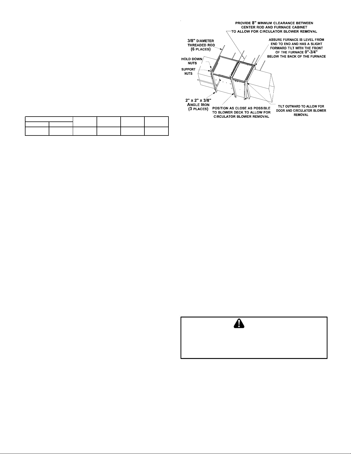
FURNACE SUSPENSION
If suspending the furnace from rafters or joist, use 3/8" threaded
rod and 2”x2”x3/8” angle iron as shown below. The length of
rod will depend on the application and the clearances necessary.
THERMOSTAT LOCATION
In an area having good air circulation, locate the thermostat
about five feet high on a vibration-free inside wall. Do not install
the thermostat where it may be influenced by any of the following:
• Drafts, or dead spots behind doors, in corners, or under
cabinets.
• Hot or cold air from registers.
• Radiant heat from the sun.
• Light fixtures or other appliances.
• Radiant heat from a fireplace.
• Concealed hot or cold water pipes, or chimneys.
• Unconditioned areas behind the thermostat, such as
an outside wall.
Consult the instructions packaged with the thermostat for mounting instructions and further precautions.
C
OMBUSTION AND VENTILA TION AIR REQUIREMENTS
WARNING
TO
AVOID PROPERTY DAMAGE, PERSONAL INJURY OR DEATH
SUFFICIENT FRESH AIR FOR PROPER COMBUSTION AND VENTILATION OF
FLUE GASES MUST BE SUPPLIED
SUPPLIED INTO THE FURNACE AREA
. M
OST HOMES REQUIRE OUTSIDE AIR BE
.
,
10
WARNING
CARBON MONOXIDE POISONING HAZARD
Failure to follow the steps outlined below for each
appliance connected to the venting system being placed
into operation could result in carbon monoxide poisoning
or death.
The following steps shall be followed with each appliance
connected to the venting system placed in operation,
while any other appliances connected to the venting
system are not in operation:
1. Seal any unused openings in the venting system.
2. Inspect the venting system for proper size and
horizontal pitch, as required by the National Fuel Gas
Code, ANSI Z223.1 or the Natural Gas and Propane
Installation Code, CSA B149.1-15 and these
instructions. Determine that there is no blockage or
restriction, leakage, corrosion and other deficiencies
which could cause an unsafe condition.
3. As far as practical, close all building doors and
windows and all doors between the space in which
the appliance(s) connected to the venting system are
located and other spaces of the building.
4. Close fireplace dampers.
5. Turn on clothes dryers and any appliance not
connected to the venting system. Turn on any
exhaust fans, such as range hoods and bathroom
exhausts, so they shall operate at maximum speed.
Do not operate a summer exhaust fan.
6. Follow the lighting instructions. Place the appliance
being inspected in operation. Adjust thermostat so
appliance shall operate continuously.
7. Test for spillage from draft hood appliances at the
draft hood relief opening after 5 minutes of main
burner operation. Use the flame of a match or
candle.
8. If improper venting is observed during any of the
above tests, the venting system must be corrected in
accordance with the National Fuel Gas Code ANSI
Z223.1/NFPA 54 and/or National Gas and Propane
Installation Code CSA B149.1-15.
9. After it has been determined that each appliance
connected to the venting system properly vents
when tested as outlined above, return doors,
windows, exhaust fans, fireplace dampers and any
other gas burning appliance to their previous
conditions of use.
AVERTISSEMENT
RISQUE D'INTOXICATION AU MONOXYDE DE CARBONE
Si les étapes décrites ci-dessous ne sont pas suivies pour
chacun des appareils raccordés au système de ventilation
au moment de sa mise en marche, cela peut entraîner une
intoxication au monoxyde de carbone ou la mort. Les
étapes suivantes doivent être suivies pour chacun des
appareils raccordés au système de ventilation au moment
de sa mise en marche, alors que tous les autres appareils
raccordés au système de ventilation ne sont pas en
marche :
1) Sceller toutes les ouvertures inutilisées du système de
ventilation.
2) Inspecter le système de ventilation afin de vérifier si la
taille et l'inclinaison par rapport à l'horizontale sont
conformes aux exigences du National Fuel Gas Code, ANSI
Z223.1/NFPA 54 ou du Code d'installation du gaz naturel
et du propane, CSA B149.1 et à ces instructions. Vérifier
qu'il n'y a pas d'obstruction ou de restriction, de fuite, de
corrosion et d'autres problèmes qui pourraient entraîner
une situation dangereuse.
3) Si possible, fermer toutes les portes et fenêtres du
bâtiment ainsi que toutes les portes séparant l'endroit où
se trouvent les appareils raccordés au système de
ventilation et les autres zones du bâtiment.
4) Fermer le registre des foyers.
5) Mettre les sécheuses en marche ainsi que tous les
autres appareils qui ne sont pas raccordés au système de
ventilation. Mettre en marche tous les ventilateurs de
tirage, comme celui des hottes de cuisine et des salles de
bains, et les régler à la puissance maximale. Ne pas mettre
en marche les ventilateurs d'été.
6) Suivre les instructions d'allumage. Mettre en marche
l'appareil soumis à l'inspection. Régler le thermostat de
manière à ce que l'appareil fonctionne en continu.
7) Vérifier la présence de fuite au niveau de l'ouverture du
coupe-tirage des appareils qui en sont dotés après 5
minutes de fonctionnement du brûleur principal. Utiliser
la flamme d'une allumette ou d'une bougie.
8) Si un problème de ventilation est observé pendant l'un
des essais décrits ci-dessus, des correctifs doivent être
apportés au système de ventilation conformément au
National Fuel Gas Code, ANSI Z223.1/NFPA 54 et (ou) au
Code d'installation du gaz naturel et du propane, CSA
B149.1.
9) Une fois qu'il a été déterminé que chaque appareil
raccordé au système de ventilation fonctionne
correctement au moyen des essais décrits ci-dessus, les
portes, les fenêtres, les ventilateurs, les registres de foyer
et tous les autres appareils de combustion alimentés au
gaz doivent être remis dans leur état initial.
If this furnace is to be installed in the same space with other
gas appliances, such as a water heater, ensure there is an
adequate supply of combustion and ventilation air for all appliances. Refer to the latest edition of the National Fuel Gas
Code NFPA 54/ANSI Z223.1 or CAN/CSA B149 Installation
Codes or applicable provisions of the local building codes for
determining the combustion air requirements for the appliances.
11
This furnace must use indoor air for combustion. It cannot be
installed as a direct vent (i.e., sealed combustion) furnace.
may NOT be rotated on *CVC8 model furnaces regardless of
installation position.
Most homes will require outside air be supplied to the furnace
area by means of ventilation grilles or ducts connecting directly
to the outdoors or spaces open to the outdoors such as attics
or crawl spaces.
CATEGORY I VENTING (VERTICAL VENTING)
WARN ING
TO
PREVENT POSSIBLE PERSONAL INJURY OR DEATH DUE TO
ASPHYXIATION, THIS FURNACE MUST BE CATEGORY
VENT USING CATEGORY
III
VENTING
.
I
VENTED
. DO
NOT
Category I Venting is venting at a non-positive pressure. A
furnace vented as Category I is considered a fan-assisted appliance and the vent system does not have to be “gas tight.”
NOTE: Single stage gas furnaces with induced draft blowers
draw products of combustion through a heat exchanger allowing, in some instances, common venting with natural draft appliances (i.e. water heaters). All inst allations must be vented in
accordance with National Fuel Gas Code NFP A 54/ANSI Z223.1
- latest edition.
NOTE: The vertical height of the Category I venting system
must be at least as great as the horizontal length of the venting
system.
WARN ING
TO
PREVENT POSSIBLE PERSONAL INJURY OR DEATH DUE TO
ASPHYXIATION, COMMON VENTING WITH OTHER MANUFACTURER’S
INDUCED DRAFT APPLIANCES IS NOT ALLOWED
.
The minimum vent diameter for the Category I venting system
is as shown:
MINIMUM VENT
MODEL
UPFLOW COUNTERFLOW
06 0 4 in c h 4 inc h
08 0 4 in c h 4 inc h
10 0 5 in c h 4 inc h
Under some conditions, larger vents than those shown above
may be required or allowed. When an existing furnace is re-
moved from a venting system serving other appliances, the
venting system may be too large to properly vent the remaining
attached appliances.
Furnaces are shipped with the induced draft blower discharging from the top of the furnace. (“T op” is as viewed for an upflow
installation.) The induced draft blower on DM80VC models can
be rotated 90 degrees for Category I venting. For furnaces
installed vertically or horizontally, a four-inch single wall pipe
can be used to extend the induced draft blower outlet 1/2” beyond the furnace cabinet. On DM80VC furnaces installed upflow or horizontally with left side down, the draft inducer may be
rotated to discharge from the right side of the cabinet. When
rotating the inducer, a chimney transition bottom kit (part #
0270F01 1 19) is needed for proper alignment of the inducer outlet and the vent exit hole in the side of the cabinet. The inducer
THIS PRODUCT IS NOT DESIGNED FOR COUNTERCLOCKWISE INDUCED DRAFT BLOWER ROT A TION.
Vent the furnace in accordance with the National Fuel Gas
Code NFP A 54/ANSI Z223.1 - latest edition.
Venting
THIS FURNACE IS NOT DESIGN CERTIFIED TO BE HORIZONT ALL Y VENTED.
To rotate the induced draft blower clockwise, you will need to
purchase one (0270F01 1 19) chimney transition bottom kit.
1. Disconnect electrical power from the furnace.
2. Disconnect the induced draft blower power leads, flue
pipe, and pressure switch tubing.
3. Remove the round cutout from the right side of the wrapper.
4. Remove and save the four screws that fasten the induced
draft blower to the flue collector box.
5. Remove and save the three screws that hold the chimney
assembly to the induced draft blower .
6. Remove and save the four screws that fasten the chimney
top to the chimney bottom.
7. Remove the chimney transition bottom from the transition
bottom kit.
8. Install the chimney top with the four screws retained
from step 6 onto the new chimney transition bottom from
the transition bottom kit.
9. Install chimney assembly with the three screws retained
from step 5 onto the induced draft blower .
10.Reinstall the induced draft blower rotating it 90 degrees
clockwise from the original upflow configuration using
the four screws retained in step 3. Ensure the gasket
located between the induced draft blower and the collector
box is rotated accordingly .
1 1. Reconnect the induced draft blower power leads. NOTE:
If the wires are not long enough, pull extra wire from the
wire bundle in the blower compartment.
12. Reconnect the flue pipe, and the pressure switch tubing.
Ensure that all wires and the pressure switch tubing is
at least one inch from the flue pipe, or any other hot
surface.
13. Restore power to furnace.
Counterflow units are shipped with the induced draft blower
discharging from the top of the furnace. (“T op” as viewed for a
counterflow installation.)
Vent the furnace in accordance with the National Fuel Gas
Code NFP A54/ANSI Z223.1-latest edition.
WARNING
N
EVER ALLOW THE PRODUCTS OF COMBUSTION, INCLUDING CARBO N
MONOXIDE, TO ENTER THE RETURN DUCTWORK OR CIRCULATION AIR
SUPPLY
.
12
E
XTERIOR MASONRY CHIMNEYS
(C
ATEGORY
I F
URNACES ONLY
This checklist is only a summary . For det ailed information on
each of the procedures mentioned, see the paragraph refer-
)
enced with each item.
An exterior masonry chimney is defined as a “Masonry” chimney exposed to the outdoors on one or more sides below the
roof line.” The ability to use a clay lined masonry chimney
depends on a parameter not associated with interior chimneys.
This variable is the geographic location of the installation. Researchers have discovered that the winter design temperatures
have a direct impact on the suitability of this type of venting. In
most situations, the existing masonry chimneys will require a
properly sized metallic liner.
WARN ING
P
OSSIBILITY OF PROPERTY DAMAGE, PERSONAL INJURY OR DEATH
DAMAGING CONDENSATION CAN OCCUR INSIDE MASONRY CHIMNEYS
WHEN A SINGLE FAN-ASSISTED CATEGORY
FURNACE) IS VENTED WITHOUT ADEQUATE DILUTION AIR
CONNECT AN
FURNACE IS COMMON VENTED WITH A DRAFT HOOD EQUIPPED
APPLIANCE OR THE CHIMNEY IS LINED WITH A METAL LINER OR TYPE
METAL VENT
SIZED IN ACCORDANCE WITH THE APPROPRIATE VENTING TABLES
80%
APPLIANCE, THE POTENTIAL FOR CONDENSATIO N DAMAGE MAY STILL
EXIST WITH EXTREMELY COLD CONDITIONS, LONG VENT CONNECTORS
EXTERIOR CHIMNEYS, OR ANY COMBINATION OF THESE CONDITIONS
HE RISK OF CONDENSATION DAMAGE IS BEST AVOIDED BY USING
T
MASONRY CHIMNEY AS A PATHWAY FOR PROPERLY SIZED METAL LINER
OR TYPE
80%
FURNACE TO A MASONRY CHIMNEY UNLESS THE
. ALL
INSTALLATIONS USING MASONRY CHIMNEYS MUST BE
FURNACE IS COMMON VENTED WITH A DRAFT HOOD EQUIPPED
B
METAL VENT
.
I
APPLIANCE
(80% AFUE
. DO
NOT
. IF AN
B
,
.
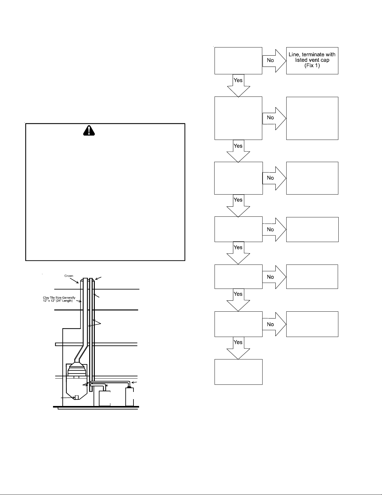
Proper Chimney
Termination?
(Check 1)
Chimney channel
free of solid and
liquid fuel
appliances?
(Check 2)
Crown in good
condition
(Check 3)
Cleanout free of
debris?
(Check 4)
Change venting
arrangements
(Fix 2)
Rebuild crown
(Fix 3)
and/or Reline
(Fix 4)
Reline
(Fix 4)
Wash
Roof Line
Clay Tile Size: 8" x 8" x12"
(Each x 24" Length )
Attic Floor
1/2" to 1" Air Space
Second Floor
Throat
Damper
Breech
Fan Assisted
Clean Out
Typical Multiple Flue Clay Tile Chimney
Forced Air
Furnace
F.A . F. Ven t
Connector
First Floor
Wate r Heater
Vent Connector
Natural Draft
Wate r Heater
Basement Floor
CHECKLIST SUMMARY
This checklist serves as a summary of the items to be checked
before venting an 80+ furnace into a masonry chimney . In addition, we recommend that a qualified serviceman use this checklist to perform a yearly inspection of the furnace venting system.
Liner in good
condition?
(Check 5)
Dilution air
available?
(Check 6)
Complete the
installation.
(Check 7)
Reline
(Fix 4)
Reline
(Fix 4)
CHECK 1 - PROPER CHIMNEY TERMINATION.
A masonry chimney used as a vent for gas fired equipment
must extend at least three feet above the highest point where it
passes through the roof. It must extend at least two feet higher
than any portion of a building within a horizontal distance of 10
feet. In addition, the chimney must terminate at least 3 feet
above any forced air inlet located within 10 feet. The chimney
must extend at least five feet above the highest connected equipment draft hood outlet or flue collar.
13
If the chimney does not meet these termination requirements,
but all other requirements in the checklist can be met, it may
be possible for a mason to extend the chimney . If this will not
be practical, see Fix 1.
10' or Less
2' Min.
Termination 10 Feet Or Less From Ridge, Wall or Parapet
Wall or
Parapet
2' Min.
Wall or
Parapet
Chimney
10' or Less
2' Min.
Chimney
More than 10’
NOTE:
No Height
above parapet
required when distance
from walls or pa r apet is
more than 10 feet.
3' Min.
3' Min.
3’ Min.
Chimney
Appliances which burn propane (sometimes referred to as LP
(liquefied petroleum)) gas are considered gas-fired appliances.
CHECK 3 - CHIMNEY CROWN CONDITION.
Damage from condensate usually shows up first in the crown.
If any of the following trouble signs are present, the condition of
the crown is not satisfactory:
a) Crown leaning
b) Bricks missing
c) Mortar missing
d) Tile liner cracked
e) No tile liner
f ) Salt staining at mortar joints. (White stains, and mortar
becomes sandy and/or erodes.)
For problems a, b, or c, see Fix 3. If problems d, e, or f are
present, see Fix 4. IMPORT ANT : It may be necessary to follow
both Fix 3 and Fix 4.
CHECK 4 - DEBRIS IN CLEANOUT.
A cleanout (dropleg) must be present such that the upper edge
of the cleanout cover is at least 12 inches below the lower edge
of the lowest chimney inlet opening.
A chimney without a cleanout could become partially blocked
by debris. If no cleanout is present, the chimney must be relined (Fix 4). Remove the cleanout cover, and examine the
cleanout for debris. If significant amounts of any of the following
are found:
• Fuel oil residue
• Bricks
• Mortar or sand
• Pieces of the tile liner
• Rusted pieces of the metallic liner - reline the chimney
(Fix 4).
More than 10’
Ridge
Termination More Than 10 Feet From Ridge, Wall or Parapet
10’
2” Min.
Chimney
Height above any
roof surface within
10 feet horizontally.
3’ Min.
CHECK 2 - ANY SOLID OR LIQUID FUEL APPLIANCES VENTED
THIS CHIMNEY CHANNEL
INTO
Solid fuel appliances include fireplaces, wood stoves, coal furnaces, and incinerators.
Liquid fuel appliances include oil furnaces, oil-fired boilers and
oil-fired water heaters.
CHECK 5 - LINER CONDITION.
If a metal liner is present, it must be checked. It cannot be
assumed that all existing metal liners are correctly installed
and in good condition.
Remove the lowest existing vent connector, and examine the
inside of the elbow or tee at the base of the liner. A small amount
of soot may be considered acceptable, provided the installer
vacuums it away. If rusted pieces of the liner have collected
here, the metal liner must be removed and replaced (Fix 4).
Next, gently tap the inside of the liner with a Phillips screwdriver. If the screwdriver perforates the liner, or if the tapping
does not sound like metal hitting metal, the liner must be removed and replaced (Fix 4).
Remember that all appliances must be vented inside the liner.
Venting one appliance inside the liner and another appliance
outside the liner is not acceptable.
14

Next, use a flashlight and small mirror to sight up the liner. B
vent must be supported so as to not come into direct contact
with the chimney walls or tile liner. If it is not, it can probably be
rehung so as to be acceptable. A thimble or fire stop may be
helpful here.
Flexible liners should be hung straight or nearly straight. If it is
spiraled in the chimney and in good condition, it should be
rehung. To do this, break the top seal; pull up and cut off the
excess liner length, and refit the top seal. Use caution when
doing this, as the cut edges of flexible liners may be sharp.
The surfaces of the liner must be physically sound. If gaps or
holes are present, the metal liner must be removed and replaced (Fix 4). Finally , confirm that the metal liner is the correct size for the appliances to be installed. Use the GAMA
tables and rules.
If a metal liner is not present, a clay tile liner must be present,
or the chimney must be lined (Fix 4).
Use a flashlight and small mirror at the cleanout or vent connector to inspect the clay tile liner. If any of the following problems are present:
• Tile sections misaligned
• Tile sections missing
• Gaps between tile sections
• Signs of condensate drainage at the cleanout or vent
connectors
• Mortar protruding from between tile sections
• Use of sewer pipe or drainage pipe rather than an
approved fire clay tile reline the chimney (Fix 4).
Gas Code NFPA 54/ANSI Z223.1 - latest edition and in the
National Standard of Canada, CAN/CSA B149.1 and CAN/CSA
B149.2 - latest editions and amendments, then the clay tile
liner can probably be used as a vent for the gas appliances.
However, the installer must keep in mind the following factors
which may render the tile liner unsuitable for use as a vent:
• Extremely cold weather
• Long vent connectors
• Masonry chimneys with no air gap between the liner
and the bricks. (In practice, this can be difficult to
detect.)
• Exterior chimneys (The tables in National Fuel Gas
Code NFP A 54/ANSI Z223.1 - latest edition and in the
National Standard of Canada, CAN/CSA B149.1 and
CAN/CSA B149.2 - latest editions and amendments
assume interior chimneys.)
If, in the judgment of the local gas utility , installer , and/or local
codes; one or more of the above factors is likely to present a
problem, the chimney must be relined (Fix 4).
FIX 1 - LINER TERMINATION
Any cap or roof assembly used with a liner must be approved
by the liner manufacturer for such use. The liner and cap/roof
assembly must then terminate above the roof in accordance
with the manufacturer’s instructions.
In some cases, a shorter extension above the roof may be
possible with a liner than would be required with a masonry
chimney .
For further information on relining, see Fix 4.
Next, measure the size of the liner. It may be possible to do
this from the cleanout. The liner must be at least as large as
the minimum size established by the tables in National Fuel
Gas Code NFPA 54/ANSI Z223.1 - latest edition and in the
National Standard of Canada, CAN/CSA B149.1 and CAN/CSA
B149.2 - latest editions and amendments. If the liner is too
small or too large, then the chimney must be relined (Fix 4).
CHECK 6 - DILUTION AIR
If gas-fired appliances are to be vented into a clay tile liner, a
source of dilution air is required.
Dilution air cannot be obtained through:
• Induced draft appliances
• Natural draft appliances with vent dampers
Sufficient dilution air can ordinarily be obtained through the draft
hood of a natural draft appliance only if the appliance’s vent
connector does not include a vent damper. If dilution air will not
be available, the chimney must be relined (Fix 4).
CHECK 7 - COMPLETE THE INSTALLATION
If Checks 1 through 6 have been satisfactory , and the liner is an
acceptable size as determined by the tables in National Fuel
FIX 2 -CHANGE VENTING ARRANGEMENTS
If the masonry chimney has more than one channel, it may be
possible to vent the gas appliances into one channel and vent
the solid or liquid fuel appliance(s) into another channel(s). Do
not vent an 80+ Furnace inside of a metal liner with other appliances vented outside the liner.
Alternatively, the homeowner may agree to discontinue use of
the fireplace (solid fuel appliance). If so, the tile liner must be
cleaned to remove creosote buildup. The fireplace opening must
then be permanently sealed.
If oil-fired appliance(s) are being replaced by gas-fired
appliance(s), the tile liner must first be cleaned to remove the
fuel oil residue.
If none of the above options is practical, the furnace may need
to be vented vertically with a B Vent.
Under some conditions, a 90%+ furnace could be installed rather
than an 80% furnace. The 90%+ furnace can be vented horizontally or vertically through PVC pipe.
15
FIX 3 - REBUILD THE CROWN
If the chimney crown is damaged, a qualified mason must repair it in accordance with nationally recognized building codes
or standards. One such standard which may be referenced is
the Standard for Chimneys, Fireplaces, Vents, and Solid Fuel
Burning Appliances, ANSI/NFPA 21 1.
FIX 4 - RELINING
Relining options include B vent and flexible liners.
If the chimney has diagonal offsets, B vent probably cannot be
used.
If B vent is to be used, it must be supported adequately . Sup-
ports (such as fire stops or thimbles) must be used to prevent
the B vent from coming into direct contact with the tile liner or
chimney walls. Direct contact would result in higher heat loss,
with an increased possibility of poor venting system performance.
• The previous liner was properly sized and installed,
and suffered from condensation damage.
• It is required by your local building codes.
Even if none of those three conditions exist which require additional liner insulation, the installer may wish to consider it if:
• The local climate is very cold.
• The chimney is very tall.
• The vent connectors used are very long or have a large
number of elbows.
• Local experience indicates that flexible liners installed
without insulation are likely to have condensation
problems.
Insulation must be selected and installed in accordance with
the liner manufacturer’s instructions.
Finally , cap the chimney and terminate the liner in accordance
with the liner manufacturer’s instructions.
It is not acceptable to vent one appliance inside the B vent and
other appliances outside. The excess space between the B
vent and the chimney walls must be covered at the top of the
chimney by a weatherproof, corrosion resistant flashing.
The B vent should then be topped with a listed vent cap. The
listed vent cap will, when installed per the manufacturer’s instructions, prevent problems due to rain, birds, or wind effects.
A B-vent installed as described in this section is considered to
be an enclosed vent system, and the sizing tables in National
Fuel Gas Code NFPA 54/ANSI Z223.1 - latest edition and in
the National Standard of Canada, CAN/CSA B149.1 and CAN/
CSA B149.2 - latest editions and amendments may be used.
If a flexible liner is to be used, it must be made of the proper
materials:
• For most residential applications, an aluminum liner
should be acceptable.
Flexible liners specifically intended and tested for gas
applications are listed in the UL “Gas and Oil
Equipment Directory”. (UL S tandard 1777).
For sizing of flexible liners, see the tables in the National Fuel
Gas Code NFPA 54/ANSI Z223.1 - latest edition and in the
National Standard of Canada, CAN/CSA B149.1 and CAN/CSA
B149.2 - latest editions and amendments.
T o inst all the liner , read and follow the liner manufacturer’s instructions and your local codes. Excess liner length should be
pulled out of the chimney and cut off. Use caution when doing
this, as the cut edges of flexible liners may be sharp. Do not
spiral excess liner inside of the chimney . Support the liner as
recommended by the liner manufacturer.
E
LECTRICAL CONNECTIONS
WARNING
HIGH VOLTAGE !
TO
AVOID THE RISK OF ELECTRICAL SHOCK, WIRING TO
THE UNIT MUST BE POLARIZED AND GROUNDED
.
WARNING
HIGH VOLTAGE !
TO
AVOID PERSONAL INJURY OR DEATH DUE TO
ELECTRICAL SHOCK, DISCONNECT ELECTRICAL POWER
BEFORE SERVICING OR CHANGING ANY ELECTRICAL
WIRING
.
CAUTION
L
ABEL ALL WIRES PRIOR TO DISCONNECTION WHEN SERVICING
CONTROLS
OPERATION
. W
IRING ERRORS CAN CAUSE IMPROPER AND DANGEROUS
. V
ERIFY PROPER OPERATION AFTER SERVICING
WARNING
HIGH VOLTAGE !
TO
AVOID THE RISK OF INJURY, ELECTRICAL SHOCK OR
DEATH, THE FURNACE MUST BE ELECTRICALLY
GROUNDED IN ACCORDANCE WITH LOCAL CODES OR IN
THEIR ABSENCE, WITH THE LATEST EDITION OF THE
N
ATIONAL ELECTRIC CODE
.
.
Some manufacturers of flexible liners offer an insulation sleeve
designed to be added to the liner before it is installed in the
chimney. (Poured insulation, either vermiculite or other materials, is no longer recommended.) Insulation will need to be added
to the flexible liner if:
• It is required by the liner manufacturer’s instructions.
16
 Loading...