

Page 1
Operation Manual
Use smart and save smart
●Thank you for purchasing intelligent Touch Controller.
●This operation manual contains notes for safe use of the
product.
For correct use, be sure to read this manual
carefully before use.
Store this manual close at hand so that it can be referred
to as required.
Model
DCS601B51
intelligent Touch Controller
We use recycled paper for making this operation manual.
Maintenance
Precautions 56
Maintenance
LCD Maintenance 57
When Leaving the Product
Turned OFF for a Long Time
57
Troubleshooting 58
Maintenance
For Your Information
Before useOperation
Before use
Safety Instructions
Be sure to follow the instructions below 1
System Overview 3
Features and Functions 4
Part Names and Functions 5
Part Names on the Monitoring
Screen and the Functions
List 9
Icon 11
Operation
Operation
Quick Reference
13
Air Conditioner Operation 14
Monitoring the Operation of Air Conditioner
22
System Setup Menu
25
For Your Information
Error Diagnostic Functions 65
Options 67
Double intelligent Touch Controllers
67
Specification 68
After-sales Service 69
Page 2
1
Instructions given here are classified into the following two categories.
Instructions in both categories are important for safety and must be duly followed.
Caution
Warning
Failure to follow the instruction may lead to serious consequences including death or
serious injury.
Failure to follow the instruction may cause injury or material damage, which, in some
cases, leads to serious consequences.
When you have read this manual, be sure to store it in a place where the operator can conveniently refer to at
anytime.
In case of personnel change, be sure to give the manual to the new operator.
The symbol given in the manual shows the following:
Do not attempt to do things described in the
instruction.
Be sure to follow the instruction.
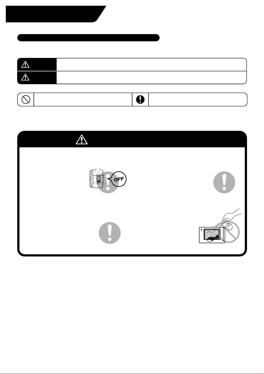
Be sure to follow the instructions below
Safety Instructions
Read the manual carefully in advance for correct use
Warning Notes on use for users
When any abnormality (such as burnt smell) is
generated, turn the power OFF and contact the
dealer you purchased the product from.
Continuing to operate with
the abnormality left
unattended may cause
failure, electric shock or fire.
For remodelling or repair, contact the dealer
you purchased the product from.
Failure to remodel or repair
properly may cause water leak,
electric shock or fire.
For transferring or reinstallation, contact the
dealer you purchased the product from.
Failure to install properly may
cause water leak, electric shock
or fire.
Do not touch the inside of the controller.
Do not remove the front panel.
Touching the inside is dangerous
and may cause failure.
For inspection and
adjustment
of the inside of the controller,
contact the dealer you
purchased the product from.
Page 3
2
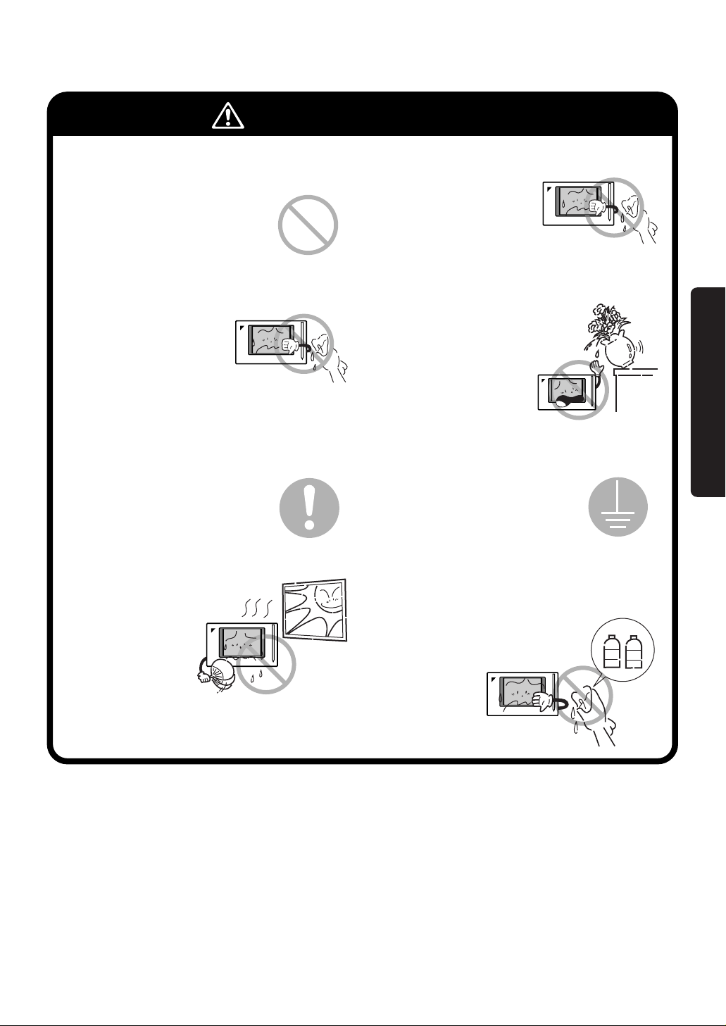
Caution Notes on use for users
Do not install in a place subject to flammable
gas.
Leakage of gas resulting in
accumulation around the unit
may lead to ignition.
Do not install in a place subject
to direct sunlight.
Failure to follow the
instruction may lead to
discoloring of the LCD
that hinders proper
display.
Be sure to provide grounding.
Do not connect the grounding
wire to any gas pipe, water pipe,
lightning rod or telephone
grounding.
Inappropriate grounding may
lead to electric shock.
Do not install the controller in a place subject
to water.
Water in the device may lead
to electrical leak and failure
in the electronic components
inside.
Do not wipe the surface of the controller touch
panel with benzine, thinner or chemicallytreated dust cloth.
Failure to follow the instruction may
lead to discoloring or peeling of the
paint. Any soiling must be wiped off
with a piece of cloth soaked in a
diluted neutral
detergent and
wrung sufficiently.
Wipe again with a
dry piece of cloth.
To clean, be sure to stop operation and turn the
power OFF.
Failure to follow the
instruction may lead to
electric shock or injury.
Washing may lead to
electric shock.
Be sure to operate with the touch pen provided.
Failure to follow the
instruction may lead to
damage or failure.
Do not wash the controller
with water.
benzine
thinner
Before use
Page 4
3
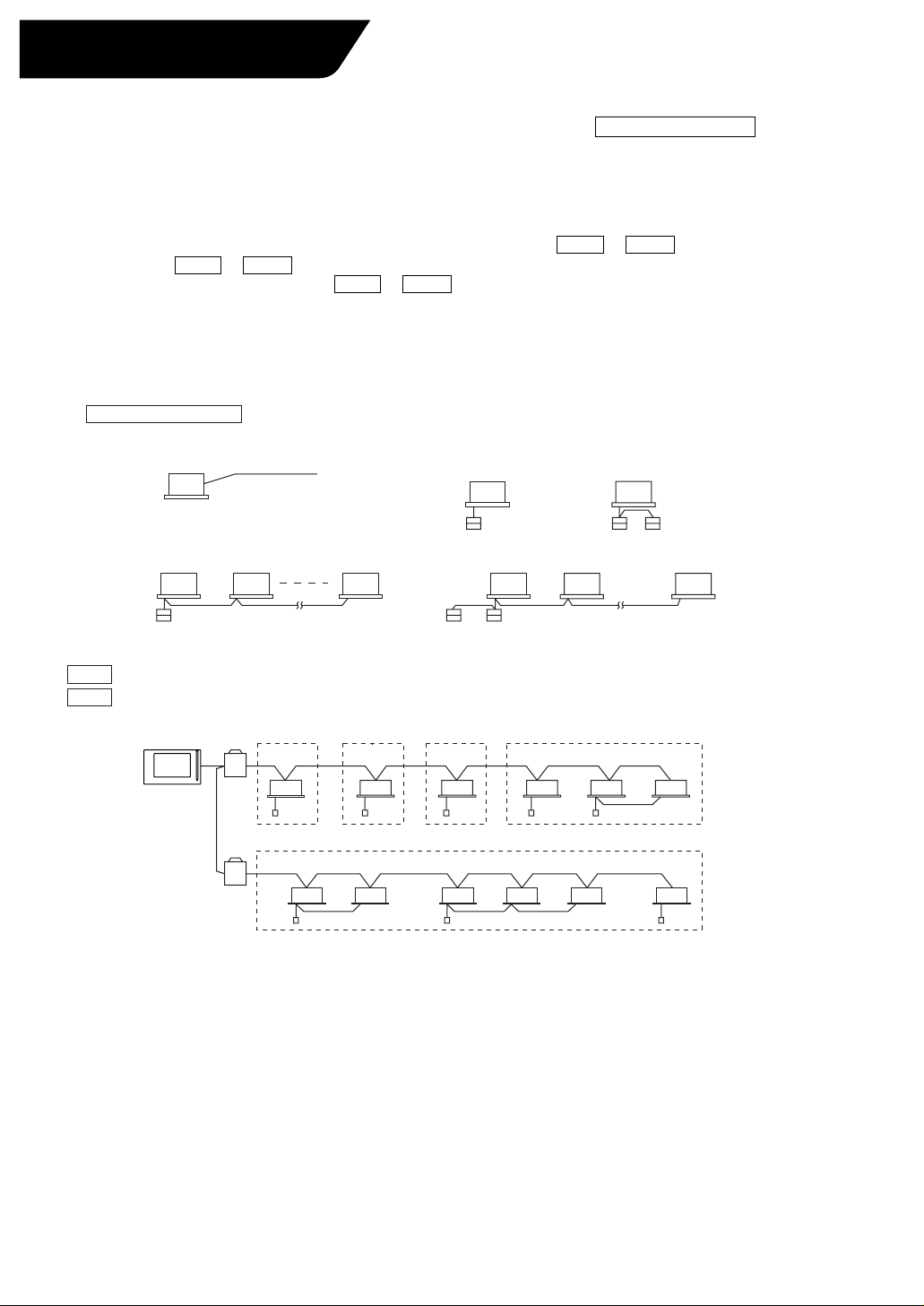
System Overview
This intelligent Touch Controller is capable of controlling/monitoring up to 64 groups of indoor units (hereafter
“groups”).
The main functions of the intelligent Touch Controller include:
1. Collective starting/stopping of operation of the indoor units connected to the
intelligent
Touch Controller.
2. Starting/stopping of operation, temperature setting, switching between temperature control modes and
enabling/disabling of operation with the hand-held remote control by zone or group .
3. Scheduling by zone or group .
4. Monitoring of the operation status by zone or group .
5. Display of the air conditioner operation history.
6. Compulsory contact stop input from the central monitoring panel (non-voltage, normally-open contact).
7. Power distribution of the air conditioners. (With the optional DCS002A51)
∗ A group of indoor units include:
∗ Zone control with the intelligent Touch Controller
∗ Zone control, which allows collective settings for more than one group, is available with the intelligent Touch
Controller, which facilitates the setting operations.
q One indoor unit without a remote control.
e Up to 16 indoor units controlled with one or two remote controls.
• One setting makes the same setting for all of the units in one zone.
• Up to 128 zones can be set with one intelligent Touch Controller.
(The maximum number of groups in one zone is 64.)
• Groups can be zoned at will with the intelligent Touch Controller.
• Units in one group can be divided into more than one zone.
w One indoor unit controlled with one or two remote controls.
intelligent Touch Controller
Zone 1
Up to 16 units Up to 16 unitsTwo remote controlsRemote control
No remote control
Remote control Remote control
or
Indoor unit
Zone 5
Zone 2 Zone 3 Zone 4
Page 5
4
Features and Functions
Operation Menu
intelligent
Touch Controller is capable of starting/stopping of the operation by the
group or zone. Collective starting/stopping is also available.
Air Conditioner Detail Setup
Temperature setting, switching between temperature control modes, switching of
speed and direction of wind and remote control mode setting are available by the
group, by the zone or collectively.
Monitoring of Various Information on Indoor Units
Information on operation such as the operation mode and temperature setting of
the indoor units, maintenance information including the filter or element cleaning
sign, troubleshooting information such as error codes can be displayed by the
group or the zone.
Zone Control Simplifying Complicated Setting Operations
Up to 64 groups can be controlled with the intelligent Touch Controller.
More than one group can be consolidated into a zone, which can be registered,
to allow the following settings by the zone. This eliminates the need for repeating
the same setting operation for each group. Function to allow collective setting for
all groups is also available.
Detailed Scheduled Operation Control
The intelligent Touch Controller allows detailed scheduled operation by the group,
by the zone or collectively. Up to 8 options for annual schedule can be set. Each
schedule can include four types of plans: for Weekdays, Holidays, Special days 1
and Special days 2. Each of the plans allows setting of up to 16 operations.
Diversified Operation Modes
Operation can be controlled both with the main unit and the remote control to
provide diversified operation management. Setting with the main unit allows the
following remote control settings by the group, by the zone or collectively:
1. Start/Stop 2. Operation Mode 3.Temperature Setting
:(Remote control) Inhibited
:(Remote control) Inhibited
:(Remote control) Inhibited
:(Remote control) Permitted
:(Remote control) Permitted :(Remote control) Permitted
:Priority
• Start/stop
• Temperature setting
• Switching between operation modes
• Setting of direction and fan speed
• Disabling/enabling the remote control
See pages
14 16
to
See pages
17 21
to
See pages
22 24
to
See page
21
See pages
14 24
to
26
See pages
27 28
to
See pages
29 38
to
Handy Automated Control
The Intelligent Touch Controller can do the following.
•
Change Over Settings: automatically switches between cooling and heating
according to the room temperature.
•
Temperature Limit Settings: prevents the temperature from rising too high or too
low in unmanned rooms.
•
Heating Optimization Settings: stops uncomfortable hot air from blowing when
the heating thermo is off.
Before use
Page 6
5
Be sure to use the touch pen for
operation of the touch panel of
the intelligent Touch Controller.
Operating with an object other
than the touch pen provided may
cause damage and failure.
Note
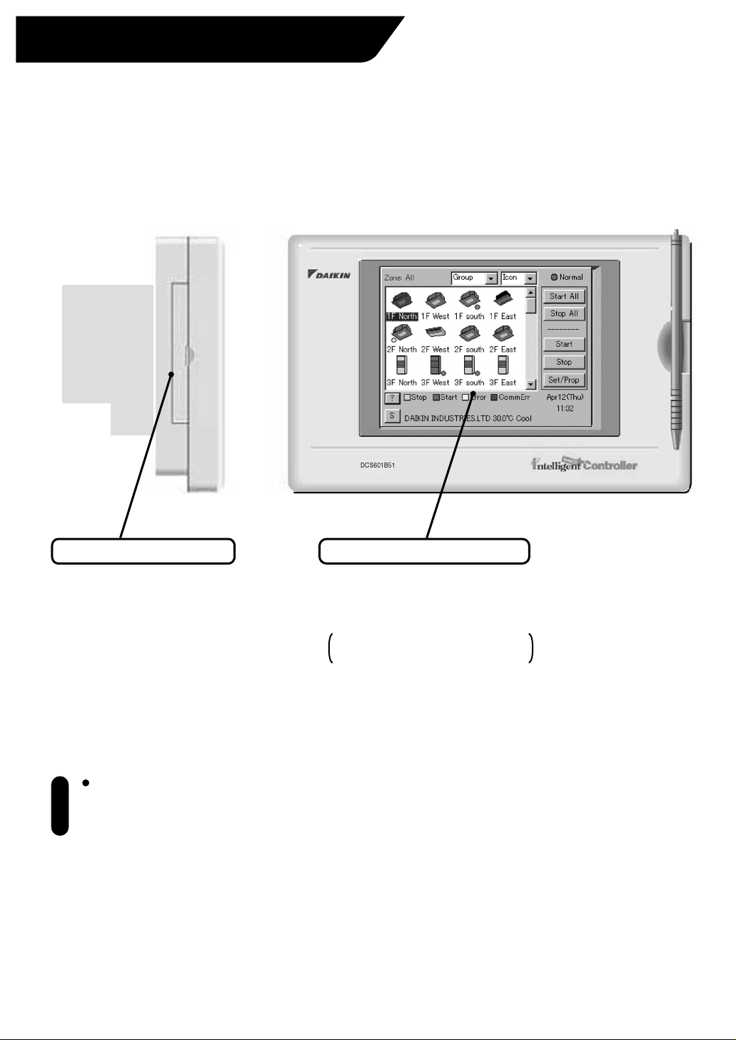
Part Names and Functions
Color LCD with Touch Panel
Provides a display for monitoring
and operation.
Be sure to use the touch pen
provided for operation.
The display shows the Monitoring
and System Setup screens.
PCMCIA Card Slot
Used when using the optional
power distribution (DCS002A51)
or updating the intelligent Touch
Controller software to a newer
version.
Page 7
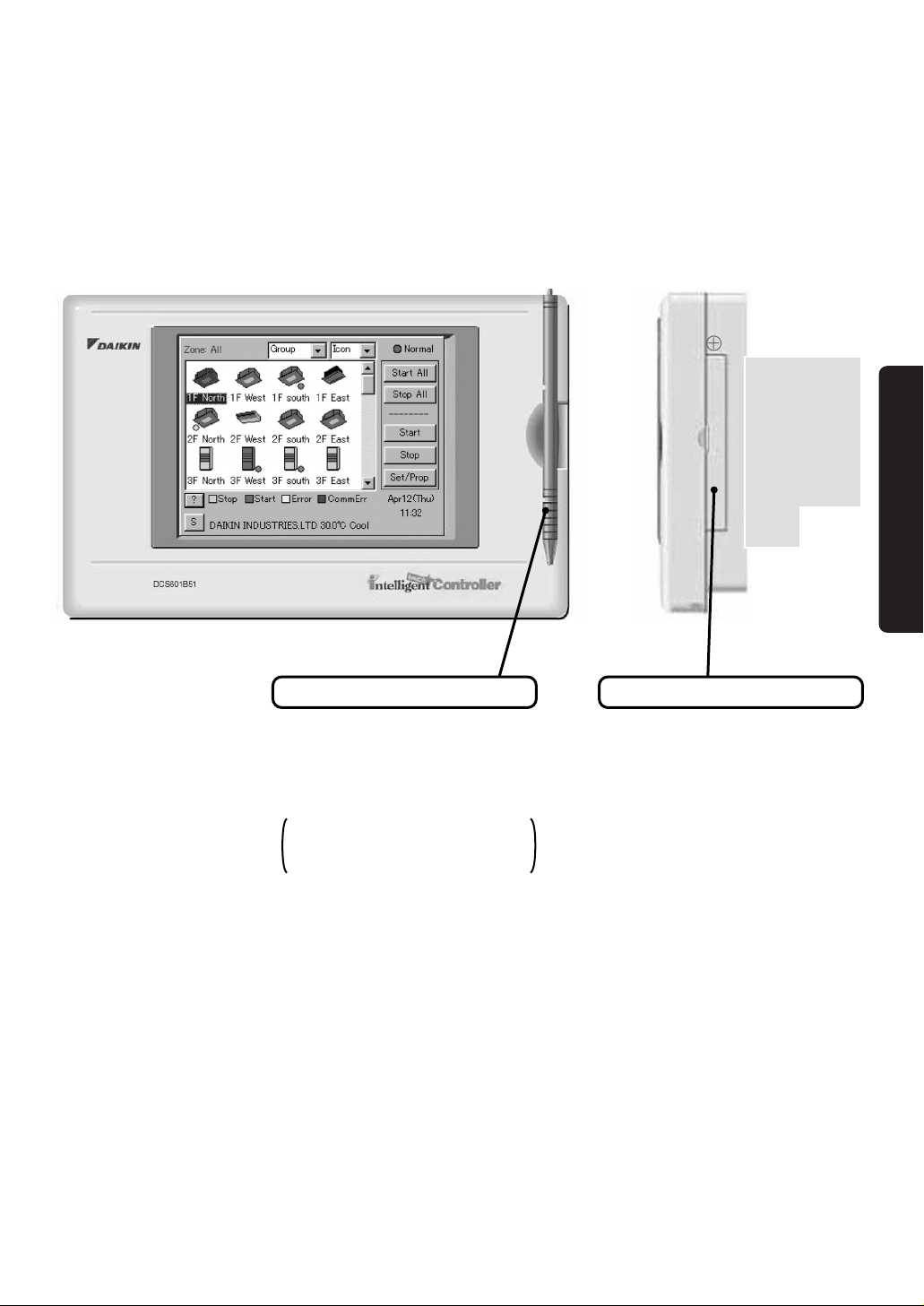
6
Maintenance Door
Generally not used. Close the
door for general use.
Use the door when adjusting the
contrast of the LCD or luminance
of the backlight.
Touch Pen
Use the touch pen for operation.
Be sure to use the touch pen for
operation.
Use caution not to lose the touch
pen.
When the pen is lost, contact the
dealer you purchased the
product from.
Before use
Page 8
7
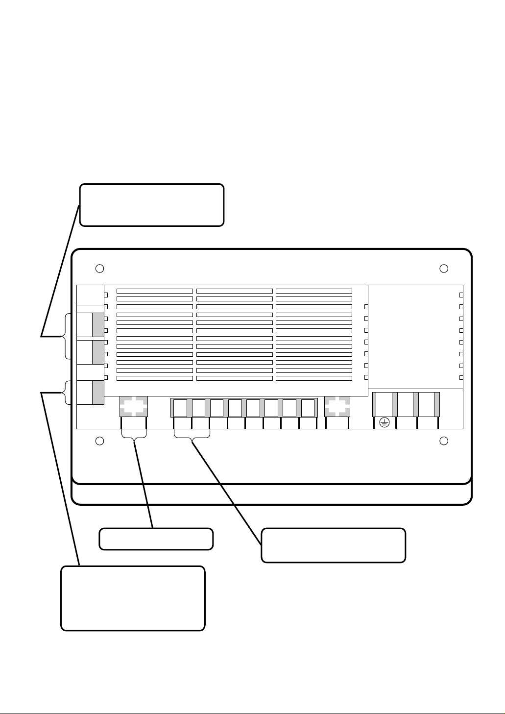
Terminals on the Back of intelligent Touch Controller
Use these ports for modem
communication when using the
AIRNET Service.
Connect the collective remote
control adapter to this connector
for “collective start of operation,”
“collective stop of operation” or
“error monitoring” remotely with a
contact signal.
This port is not used with
this model.
Connect a non-voltage contact for
collective stopping of operation
with a contact signal.
232C-1 232C-2
CN2
Ethernet LON
L2 L1
COM Dil Pi3 COM Pi2 Pi1 F2 F1
Page 9
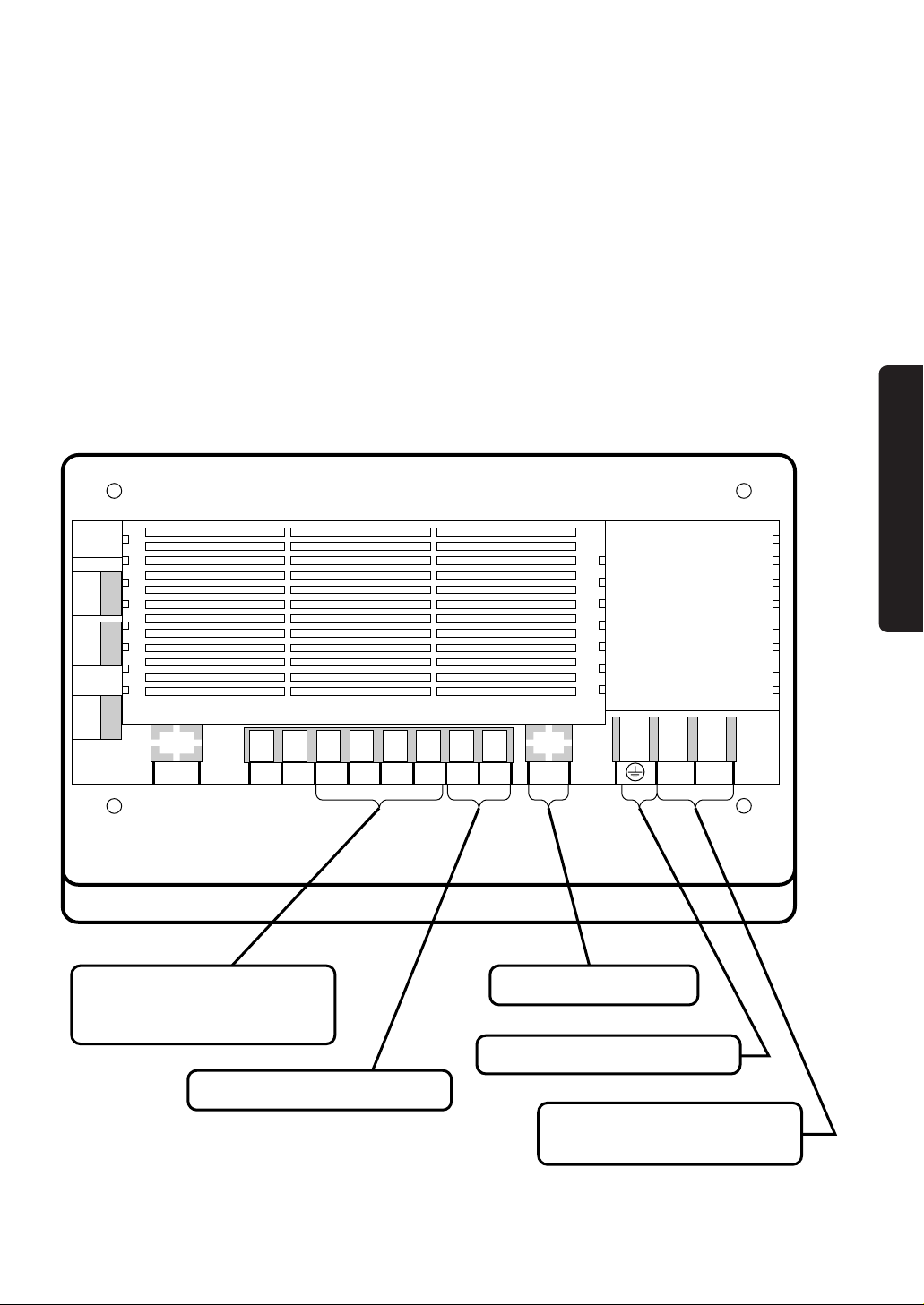
8
Connect a watt-hour meter when
using the optional power
distribution function software
(DCS002A51).
Terminals for communication with
air conditioning system.
Terminal for the grounding wire.
Terminals for the power supply.
Connect single-phase power of
100 to 240 VAC, 50/60 Hz.
232C-1 232C-2
CN2
Ethernet LON
L2 L1
COM Dil Pi3 COM Pi2 Pi1 F2 F1
This port is not used with
this model.
Before use
Page 10
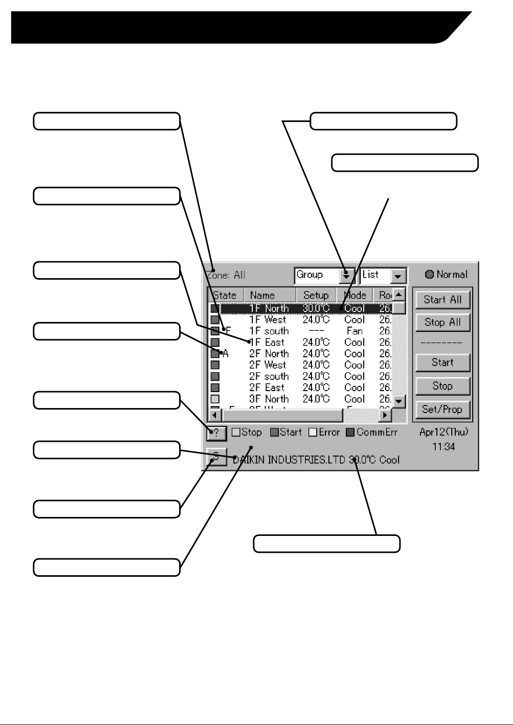
Contents of the List Currently Displayed
• When Group List is displayed
“Zone: Zone Name”
• When Zone List is displayed
“Zone List”
Display Mode Selection
Select between Zone and Group.
Zone/Group Name
Set the names in the Group
Registration or Zone Registration
in the System Setup Mode.
Filter/Element Sign
Displayed when there is any air
conditioner showing a filter or
element sign in the zone or the
group.
Target of Automatic Control
Displayed when there is any air
conditioner with the registration of
scheduled or change over or temperature
limit or heating mode optimization
operation in the zone or in the group.
Monitoring Screen Legend
Pressing the “?” button shows
more detailed legend.
Button to Switch to the System Setup Mode
Use this button for settings
including the time, group, zone
and schedule.
Description of Zone/Group
Set the names in the Group
Registration or Zone Registration
in the System Setup Mode.
System Status Display Area
Area for displaying the system
status (compulsory stop, etc.).
9
Part Names on the Monitoring Screen and the Functions
List
Information on Zone/Group Currently Displayed
Generally, the temperature setting and
the operation mode are displayed.
If any error occurs in the air conditioner,
the error code is displayed.
Zone/Group Currently Displayed
The name of the zone/group
currently selected is highlighted.
Page 11
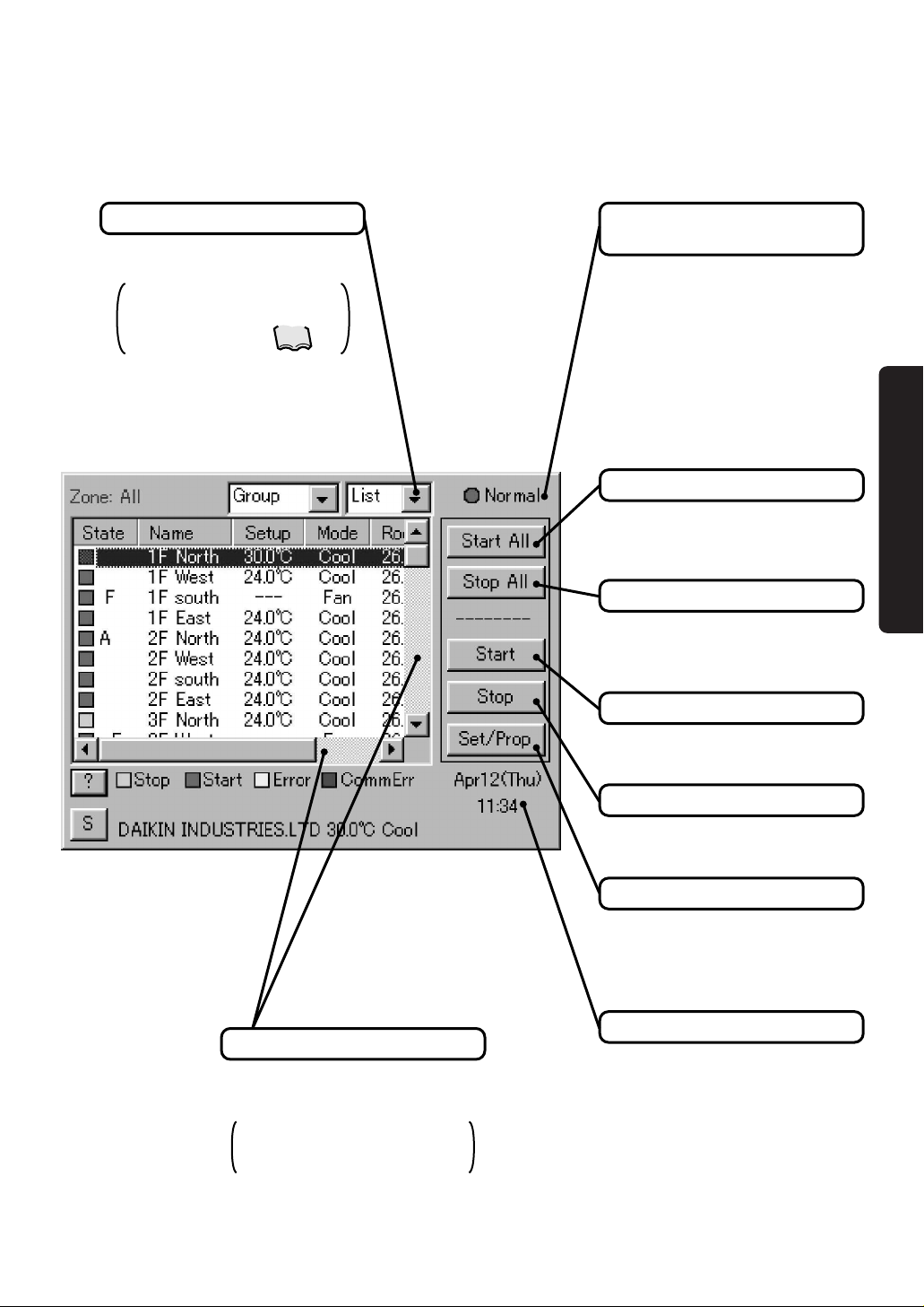
10
Scroll Bars
Use the bars to monitor any area
of the group/zone list not
currently shown.
Sliding the bars up/down and
left/right changes the range
monitored.
Display Type Selection
Select the type between Icon and
List.
The example below shows
the List Display. For Icon
Display, see pages .
Display for Collective Monitoring of Air
Conditioners Connected to intelligent Touch Controller
When operation is normal and any air
conditioner is in operation:
Red/Normal
When operation is normal and all air
conditioners are in stoppage:
Green/Normal
When there is any air conditioner
generating an error:
Yellow/Abnormal
When there is any air conditioner with
communication error:
Blue/Abnormal
Start All Button
Button to collectively start all the
air conditioners connected to
intelligent Touch Controller.
Stop All Button
Button to collectively stop all the
air conditioners connected to
intelligent Touch Controller.
Group/Zone Start Button
Button to start operation of the
group/zone selected.
Group/Zone Stop Button
Button to stop operation of the
group/zone selected.
Group/Zone Set/Prop Button
Makes detailed settings
(temperature setting, temperature
control mode, etc.) and display of
the group/zone selected.
Current Time Display
Shows the current date and time.
11,12
Before use
Page 12

Contents of the List Currently Displayed
• When Group List is displayed
“Zone: Zone Name”
• When Zone List is displayed
“Zone List”
Display Mode Selection
Select between Zone and Group.
Information on Zone/Group Currently Displayed
Generally, the temperature setting
and the operation mode are
displayed. If any error occurs in the
air conditioner, the error code is
displayed.
Zone/Group Currently Displayed
The name of the zone/group
currently selected is highlighted.
Zone/Group Name
Set the names in the Group
Registration or Zone Registration
in the System Setup Mode.
Filter/Element Sign
Displayed when there is any air
conditioner showing a filter or
element sign in the zone or the
group.
Target of Automatic Control
Displayed when there is any air
conditioner with the registration of
scheduled or change over or temperature
limit or heating mode optimization
operation in the zone or in the group.
Monitoring Screen Legend
Pressing the “?” button shows
more detailed legend.
Button to Switch to the System Setup Mode
Use this button for settings
including the time, group, zone
and schedule.
Description of Zone/Group
Set the names in the Group
Registration or Zone Registration
in the System Setup Mode.
System Status Display Area
Area for displaying the system
status (compulsory stop, etc.).
11
Icon
Page 13

Scroll Bars
Use the bars to monitor any area
of the group/zone list not
currently shown.
Sliding the bars up/down and
left/right changes the range
monitored.
Display for Collective Monitoring of Air
Conditioners Connected to intelligent Touch Controller
When operation is normal and any air
conditioner is in operation:
Red/Normal
When operation is normal and all air
conditioners are in stoppage:
Green/Normal
When there is any air conditioner
generating an error:
Yellow/Abnormal
When there is any air conditioner with
communication error:
Blue/Abnormal
Start All Button
Button to collectively start all the
air conditioners connected to
intelligent Touch Controller.
Stop All Button
Button to collectively stop all the
air conditioners connected to
intelligent Touch Controller.
Group/Zone Start Button
Button to start operation of the
group/zone selected.
Group/Zone Stop Button
Button to stop operation of the
group/zone selected.
Group/Zone Set/Prop Button
Makes detailed settings
(temperature setting, temperature
control mode, etc.) and display of
the group/zone selected.
Current Time Display
Shows the current date and time.
Display Type Selection
Select the type between Icon and
List.
The example below shows
the Icon Display. For List
Display, see pages .
9, 10
12
Before use
Page 14

13
Quick Reference
Air Conditioner Operation
To collectively start/stop the operation of all devices connected
to the intelligent Touch Controller
To start/stop the operation of devices by zone
To start/stop the operation of devices by group
To change the operation mode
To change the temperature setting
To change the direction or fan speed
To change the range of operation allowed with remote control
Air Conditioner Operation Monitoring
To monitor by zone or by group
To monitor detailed information
System Setup Menu
To change the name of a group
To change the zone setup
To change the schedule setup
To calibrate the touch panel
To adjust the contrast of the screen
To review the history of errors
See page
14
15
to
See page
16
See page
17
See page
18
See page
To reset the filter or element sign
19
See page
20
See page
21
See page
22
See page
26
See page
26
See page
39
See page
39
See page
64
See page
23 24
See pages
to
27 28
See pages
to
29 33
See pages
to
34 36
See pages
to
37 38
See pages
To change the change over settings
To change the temperature limit settings
To change the heating optimization settings
Page 15

14
Air Conditioner Operation
Starting/Stopping Operation Collectively
1
2
3
Screen 1 Monitoring
Screen 2 Confirm
To start/stop the operation of
all devices connected
1.
2.
Screen 2 Confirm appears. Press the
OK e button.
To exit without activating collective
start or stop, press the Cancel button.
Start or stop collectively the operation of
devices connected.
On the Monitoring screen, operation is
allowed with either Zone or Group as the
display mode and with either Icon or List as
the display type. In the example on the left,
the display mode is Group in the collective
mode and the display type is Icon.
On Screen 1 Monitoring, press the Start
All q or Stop All w button.
[Procedure]
Operation
Page 16

15
Screen 1 Monitoring
To start/stop the operation of
devices by group
1.
On Screen 1 Monitoring, select a zone
from the pull-down menu q.
Start or stop the operation of air conditioners
by group.
The example on the left shows the
screen for starting/stopping the
operation of Group Name: 1F North
registered for Zone Name: Canteen.
2.
Select a zone that includes the group of
which the operation is to be started or
stopped w.
3.
4.
Select a group to be started or stopped
as in e and press the Start r or Stop
t button.
Starting/Stopping Operation by the Group
Screen 2 Monitoring (Group)
1
2
3
4
5
Select a group from the pull-down menu
q.
Screen 2 Monitoring (Group) appears.
Zone Name
Canteen
1F North
1F West
1F South
1F East
2F North
2F West
2F South
2F East
3F North
Air conditioner
group to be
started or
stopped
[Procedure]
Page 17

16
Collective Zone
Zone Name
Office
Canteen
Meeting
1F
2F
3F
Air conditioner
group to be
started or
stopped
Screen 1 Monitoring
To start/stop the operation of
devices by group
1.
On Screen 1 Monitoring, select a zone
from the pull-down menu q.
2.
Starting/Stopping Operation by the Zone
3
4
1
2
Select the zone of which the operation
is to be started/stopped as shown in w.
3.
Press the Start e or Stop r button.
Start or stop by zone the operation of groups
of air conditioners set in zones.
The example on the left shows a screen for
starting or stopping the operation of air
conditioners in the canteen.
[Procedure]
Operation
Page 18

17
Screen 1 Monitoring
1.
On Screen 1 Monitoring, select a zone
or a group from the pull-down menu q.
Switch the operation mode of the air
conditioner.
On the Monitoring screen, operation is
allowed with either Icon or List as the display
type.
The operation mode can be switched by
zone or by group.
Selecting a zone and switching the
operation mode switches the mode of
all air conditioners in the zone.
Selecting a group and switching the
operation mode switches the mode of air
conditioners in the group selected.
Ex.: For the following zone setting, the
operation modes available are Fan,
Cool, Heat and Auto.
If Cool/Heat option is not available for
any air conditioner in the zone, Fan and
Set Point are the available operation
modes.
2.
Select with w a zone or a group of
which the operation mode is to be
switched.
3.
Press the Set/Prop button e.
Screen 2 Operation appears.
4.
Select Set for the Operation Mode r.
Select the operation mode to be set
from the pull down menu t.
5.
Switching the Operation Mode
Screen 2 Operation
3
4
5
6
2
1
To cancel the setting, press the
Cancel button.
On the menu, operation modes
available for air conditioners in the
zone are displayed if the switching
is to be made by zone. See the
example below.
Press the OK button y.
Zone name Group name
Operation modes available
Canteen
1F North “Cool” “Air”
“Cool” “Heat”
“Auto” “Air”
1F West
[Procedure]
Page 19

18
Screen 1 Monitoring
1.
On Screen 1 Monitoring, select a zone or a
group from the pull-down menu q.
Change the temperature setting of air conditioners.
On the Monitoring screen, operation is allowed
with either Icon or List as the display type.
The temperature setting can be switched by zone
or by group.
Selecting a zone and changing the temperature
setting changes the setting of the air conditioner
groups in Cool, Heat, Auto or Temp operation in
the zone.
Selecting a group and changing the temperature
setting changes the temperature setting of air
conditioners in the group selected.
If all of the air conditioners in the group
selected are in Fan operation, temperature
setting cannot be changed.
2.
Select a zone or a group of which the
temperature setting is to be changed w.
3.
Press the Set/Prop button e.
Screen 2 Operation appears.
4.
Select Set for the Set Point r. Set the
integer part of the setting in t and the
decimal part in y.
Ex.: For the following zone setting, the
temperature settings available are between
20°C and 30°C inclusive.
When the temperature setting is 30°C, the
actual temperature settings for air
conditioners are as shown below:
Note: Range of temperature settings available is
the range specified in accordance with the
following.
●
Range of temperature setting inherent to
the air conditioner main unit.
●
Range of temperature as a result of the
restriction by the temperature setting limit.
5.
Changing the Temperature Setting
Screen 2 Operation
1
2
3
4
5 6 7
To cancel the setting, press the Cancel
button.
On the menu, temperature settings
available for air conditioners in the zone
are displayed if the setting is to be made
by the zone. See the example below.
Press the OK button
u
.
Zone name Group name
Range of temperature
settings available
(see Note)
Group name
Temperature setting
Canteen
1F North 25 to 30
°C
20 to 25
°C
1F West
1F North 30
°C
25
°C
1F West
[Procedure]
See page
44
Operation
Page 20

19
Screen 1 Monitoring
1.
On Screen 1 Monitoring, select a zone
or a group from the pull-down menu q.
Reset the filter or element sign after
cleaning any air conditioner showing the
filter or element sign.
On the Monitoring screen, operation is
allowed with either Icon or List as the display
type.
The filter or element sign can be reset by
zone or by group.
2.
Select a zone or a group of which the
filter or element sign is to be reset w.
3.
Press the Set/Prop button e.
Screen 2 Operation appears.
4.
Press the Advanced Func button r.
Screen 3 Advance Function appears.
5.
To reset the filter sign, select Yes for
Filter Sign Reset t.
To reset the element sign, select Yes
for Element Sign Reset y.
Then press the OK button u.
To cancel the setting, press the
Cancel button.
Screen 2 Operation reappears.
Resetting the Filter/Element Sign
Screen 2 Operation
6.
1
2
3
4
8
Screen 3 Advanced Operation
5
6
7
To cancel the setting, press the
Cancel button.
Then press the OK button i on Screen
2 Operation.
[Procedure]
Page 21

20
Screen 1 Monitoring
1.
On Screen 1 Monitoring, select a zone
or a group from the pull-down menu q.
Change the fan direction or volume of air
conditioners.
On the Monitoring screen, operation is allowed
with either Icon or List as the display type.
The fan direction or volume can be changed by
zone or by group.
2.
Select a zone or a group of which the
fan direction or volume is to be reset w.
3.
4.
Press the Advanced Func button r.
Screen 3 Advance Function appears.
To change the wind volume, select Set for
Wind Volume u. Select between High
and Low with the pull-down menu i.
To cancel the setting, press the
Cancel button.
Screen 2 Operation reappears.
5.
Changing the Direction/Fan Speed
Screen 2 Operation
6.
To cancel the setting, press the
Cancel button.
1
2
3
4
10
Screen 3 Advanced Operation
5
7
98
6
The larger the value for wind direction
setting (0 - 6), the closer to vertical the
direction becomes. The value 7
indicates automatic swing.
(Note: See the figure below.)
The description given above may not
exactly apply depending on the model.
Check the wind direction sign on the
remote control after operation.
To change the fan direction, select Set for
Wind Direction t. Set the direction with
the pull-down menu y.
Then press the OK button o.
Then press the OK button !0 on Screen
2 Operation.
Note: Guidelines for wind direction value and
actual direction
0
4
5
6 7: Wind direction auto
swing
Indoor unit
[Procedure]
Press the Set/Prop button e.
Screen 2 Operation appears.
Operation
Page 22

21
Screen 1 Monitoring
1.
On Screen 1 Monitoring, select a zone
or a group from the pull-down menu q.
Change the setting of operation with the remote
control of air conditioners between Permitted and
Prohibited.
On the Monitoring screen, operation is allowed
with either Icon or List as the display type.
The setting between Permitted and Prohibited
can be changed by zone or by group.
2.
Select with w a zone or a group for which
the setting of the range of operation allowed with remote control is to be reset.
3.
4.
Press the Advanced Func button r.
Screen 3 Advance Function appears.
5.
Press Set for R/C Mode t. Then make
setting with the pull-down menus y - i.
There are three settings as shown below:
yStart/Stop
“Prohibited”
“Stop Only”
“Permitted”
uOperation Mode
“Permitted or Prohibited”
iSet Point
Permitted or Prohibited
Changing the Range of Operation Allowed with Remote Control
Screen 2 Operation
6.
1
2
3
4
10
Screen 3 Advanced Operation
9
5
6
7
8
To cancel the setting, press the
Cancel button.
Screen 2 Operation reappears.
To cancel the setting, press the
Cancel button.
Press the OK button o after setting
y - i.
Then press the OK button !0 on Screen
2 Operation.
Item Setting Meaning
Start/Stop
Prohibited
The remote control cannot
start or stop operation.
The remote control can start
or stop operation.
The remote control can
change the operation mode.
The remote control cannot
change the operation mode.
The remote control can change
the temperature setting.
The remote control cannot
change the temperature setting.
The remote control can stop the
operation of air conditioners in
operation but cannot start air
conditioners not in operation.
Stop Only
Permitted
Permitted
Prohibited
Permitted
Prohibited
Operation
Mode
Set Point
[Procedure]
[Details of Setting]
Press the Set/Prop button e.
Screen 2 Operation appears.
Page 23

22
Monitoring the Operation of Air Conditioner
Screen 1 Monitoring (Icon)
The display type of the operation monitor can be
selected between Icon and List.
To select, use the pull-down menu
q
to choose
either Icon or List.
Monitoring can be selected between by Zone and
by Group.
To select, use the pull-down menu
w
to choose
either Zone or Group.
The example on the left shows the following:
For Screen 1, Display type: Icon; Monitoring by: Group
For Screen 2, Display type: List; Monitoring by: Zone
[Display on the Screen]
Display area e allows monitoring the start/stop
status of the zone or group, whether any error
has occurred, whether automatic control is set
and the status of the filter/element sign.
Moving the scroll bar
r
up and down changes
the area that can be viewed.
When the number of zones or groups
registered is small enough to be covered by
the area viewed at one time, no scroll bar is
shown. (Ex.: Screen 2)
The display
t
shows a legend.
For more detailed legend, press the “?” button
y
. Screen 3 Legend appears. To go back to the
previous view, press the Close button u.
The highlighted display
i
shows the zone or
group currently selected. Touching the screen
allows selecting another zone or group.
Display
o
shows the settings for the zone or
group selected with i. The settings include the
following (from left):
• Zone or group name
Display
!
0 is an indicator for checking at a
glance the status of all air conditioners connected
to the intelligent Touch Controller.
Meanings of indications are as shown below:
When operation is normal and any air conditioner is in operation: Red
When operation is normal and all air conditioners are in stoppage: Green
When there is any air conditioner generating an error: Yellow
When there is any air conditioner with communication error: Blue
Screen 2 Monitoring Screen (List)
Screen 3 Legend
To monitor by the zone or by
group
To Monitor the Operation by the Zone or Group
• Temperature setting
• Operation mode
for a zone, the temperature setting of the
representative unit is shown. (See Note)
for a zone, the operation mode of the
representative unit is shown. (See Note)
3
2
4
5
9
5
9
7
10
3
6
6
1
1
10
8
8
2
(Note): Representative unit for a zone
One group shows a representative unit
when monitoring is performed by the
group on the Monitoring screen as
described below:
● Icon display: the leftmost group
shown in the top line
● List display: the group shown in the
top line
See page 46 for changing the
representative unit for a zone.
See page
46
Operation
Page 24

23
Detailed operation status can be monitored by zone or by group.
The contents of Display on Screen 2 are as shown below.
Obscured indication for
r - y shows the current status
of the zone or group selected.
The example on the left shows the following:
u includes the following as the maintenance information:
To monitor detailed information on one zone or group
The display on Screen 2 and Screen 3, which is on the following page, is updated
when the screen appears. Once the screen is open, it is not undated before it is
closed and opened again.
The display type for monitoring detailed operation status can
be selected between Icon and List.
Monitoring Detailed Information
Screen 1 Monitoring (Icon)
Screen 2 Operation
[ Group ]
Name
Description
ID
Type
D3 Address
Schedule
Heating Optimization
Heating Mode Optimization
Temperature Limit
Temperature Limit Ctrl
Change Over
Slv R/C
Cool/Heat Option
Ou/Unit Addr
Err Type
Err Code
Err Unit No
Rm Temp
[ Zone ]
Name
Description
ID
Start 1 by 1
Interval
Registered Grp No
Schedule
Slv R/C
Cool/Heat Option
Ou/Unit Addr
Err Type
Err Code
Err Unit No
Rm Temp
: Zone name
: Zone description
: 0 - 63
: Enabled/Disabled
: Interval when Enabled is set for the above
: The number of groups registered for a zone
: Enabled/Disabled
: Mst/Slv (*1)
: With/Without (*2)
: Address of the outdoor unit (*3)
: Normal; Error code when any error is generated (*4)
: 2-digit error code when any error is generated (*4)
: 0 when there is no error
Unit No. when error is generated (*4)
: Inlet temperature of the representative group for a zone (*1)
: Group name
: Group description
: 0 - 63
: Air conditioner or device
: Address between 1-00 and 4-15
: Enable/Disabled
: Enabled/Disabled
: Only displayed during control.
: Enable/Disable
: Only displayed during control.
: Enable/Disable
: Mst/Slv
: With/Without
: Address of the outdoor unit
: Normal; Error code when any error is generated
: 2-digit error code when any error is generated
: 0 when there is no error
Unit No. when error is generated
: Inlet temperature of the indoor unit
On/Off
Operation Mode
Set Point
: Start
: Cool
: 24.0
°C
For detailed information on a zone, the indication (*1) is Mst
when there is any master R/C is included for air conditioners in
the zone and Slv when all of them are slave R/C. The indication
(*2) is Enabled when any of the air conditioners in the zone has
the Cool/Heat option and Disabled when none of them has the
option. The indication (*3) shows information on the
representative unit for a zone and the error-related indications
(*4) show information on any air conditioner generating an error.
For monitoring further detailed information,
2
1
3
5
4
8
7
9
6
1.
Select Zone or Group from the pull-down menu
w.
(The example on the left shows Group selected.)
2.
Press the Set/Prop button e.
Screen 2 Operation appears.
3.
Press the Advanced Func button i.
Screen 3 Advanced Function appears as shown
on the following page.
To go back to Screen 1 Monitoring, press the
Cancel button o.
When Zone is selected, r - y on Screen 2 and !2 - !6 on
Screen 3 on the following page show the status of the
representative unit for a zone. For
!0
and !1 on Screen 3, if
any of the air conditioner of the group in the zone has the filter
or element sign illuminated, Yes/No here is shown in black.
Page 25

24
7:
Wind direction auto swing
Note: Guidelines for wind direction value and
actual direction
Screen 3 Advanced Operation
The contents of Display on Screen 3 Advanced
Operation are as shown below.
!0Filter Sign Status
When Yes/No is shown in black, the filter sign is
illuminated.
!2Shows the current wind direction.
Indicated with a figure between 0 and 7 inclusive.
The larger the value for wind direction setting
(0 - 6), the closer to vertical the direction
becomes. The value 7 indicates automatic
swing.
(Note: See below.)
The description given above may not exactly
apply depending on the model. Check the
wind direction sign on the remote control after
operation.
!1Element Sign Status
When Yes/No is shown in black, the element
sign is illuminated.
(The example on the left shows the filter sign
illuminated.)
!3Shows the current wind volume.
Low or High is shown.
!4Shows the remote control setting for starting or
stopping operation. One of the following is
shown:
Prohibited
Stop Only
Permitted
!5Shows the remote control setting for the
operation mode. One of the following is shown:
Prohibited
Permitted
Screen 2 Operation on the previous page
reappears.
Pressing the Cancel button
o on that screen
brings you back to Screen 1 Monitoring.
This screen is for both operation and
monitoring. When you have used the
screen for monitoring only, press the
Cancel button rather than the OK
button to exit the window to prevent
wrong operation.
Continued from the previous page
10
11
12
14
15
16
17
13
0
4
5
6
Caution
!6Shows the remote control setting for the
temperature setting. One of the following is
shown:
Prohibited
Permitted
4.
When all the settings have been
confirmed, press the Cancel button !7.
Indoor unit
Operation
Page 26

25
System Setup Menu
The System Setup menu includes the following items:
Operation
(Reference)
System Setup
Menu Item
Description
Setting a password allows restriction of access to the System Setup menu
operation to specified personnel
Note : If the set password is lost, access to all System Setup menu
operation is denied.
Use caution not to lose the password.
If it is lost, consult the dealer you purchased the product from.
Password
Setup
• Password Setup
• Time Zone Setup
• Time Setup
• Backlight Setup
• Group Setup
• Zone Setup
• Schedule Setup
• Change Over Settings
• Temperature Limit Settings
• Heating Optimization Settings
Adjust the system clock (year, month, day, hour, minute and second).
The clock is used for scheduled operation, saving history, power distribution
(optional) and demand operation (optional).
Note : Adjusting the clock may affect scheduled operation, power distribution
or demand operation.
For the details of the influence, see the following. For power
distribution and demand operation, see the respective
instruction manual as well.
[Influence of changing the clock setting on scheduled operation]
• The operation scheduled to run at a time passed by advancing the clock is
not performed.
Ex.: When an air conditioner is scheduled to start at 10:00 (q):
If the time is adjusted to 10:05 at 9:55, the scheduled operation
(q) is not performed.
• The operation scheduled to run at a time reached again by turning back
the clock is performed again.
Ex.: When an air conditioner is scheduled to start at 10:00 (q):
If the time is adjusted to 9:55 at 10:05, the scheduled operation
(q) is performed again at 10:00.
Time Setup
It is necessary to set Time Zone of intelligent Touch Controller according to
your service place. And when it is needed to set Daylight Saving Time,
setting may be made by this menu.
Note : Setting Time Zone Setup may affect upon schedule operation, electric
proportional distribution, and demand operation.
As for concrete influences, refer to the following. And as for
electric proportional distribution and demand operation, refer to
their respective operation manuals.
Time goes ahead 60 minutes at the start of Daylight Saving Time, while time
goes back 60 minutes at the completion. As for the influence, there are
same influences as in the case time is made ahead and back in the following
section Time Setup. Refer to the applicable description.
Time Zone
Setup
The following table describes the items mentioned above.
See page
41
See page
43
See page
42
• History Display
• Touch Panel Calibration
• Version Information
Page 27

26
Operation
(Reference)
System Setup
Menu Item
Description
A backlight is used for the LCD of the intelligent Touch Controller. The backlight
has its service life and the luminance of the backlight is reduced in proportion to
the period of time it is illuminated. This setting is for preventing the luminance
from being reduced in a short time by automatically turning the backlight OFF
when the touch panel has been left untouched for a set period of time.
If the backlight has been turned off automatically, touching the panel illuminates
the backlight again.
Backlight setting includes the following two steps:
1.Set the time before the backlight is automatically turned OFF.
Range: 1 - 60 minutes in increments of one minute.
2.Set whether the backlight should be automatically illuminated when any error is
generated in the air conditioner while the backlight is turned OFF.
Enable/Disable
Note: If this setting is not made, the backlight generally requires replacement every 3
- 4 years.
The life of the backlight becomes even shorter if it is illuminated in a low
temperature (10°C or lower) environment for a long time.
When using the intelligent Touch Controller in a low temperature environment,
it is recommended that a shorter time is set for 1. above and Disabled for 2.
Backlight
Setup
Set the name, description, icons to be displayed and temperature setting limit
(see Note) for the group.
If this registration is not made, addresses for central management of the group is
used for the Name and Description. Operation is not affected if these settings
are not made.
Addresses for central management include up to 64 addresses 1-00, 1-01, ......
1-15, 2-00, ...... 4-15.
(Note): The temperature setting limit is a function to allow operation only within
the preset temperature limit to prevent too much cooling or heating.
(The limit function above does not work when the operation mode of the
air conditioners is Auto.)
Ex.: Temperature setting limit: 25 - 35°C cooling
If the temperature is set to 20°C with the remote control, the intelligent
Touch Controller automatically changes the temperature setting to 25°C.
Group Setup
Set the name, description, icons to be displayed and sequential starting of the
groups registered for a zone (see Note), and groups to be registered for the zone.
The zone includes “Collective,” for which all groups are registered in advance.
This zone is made available for making the settings for all of the air
conditioners connected to the intelligent Touch Controller. The name,
description or registered groups cannot be changed for this Collective zone.
(Note): Setting sequential starting of groups registered for the zone
When multiple groups are registered for a zone and operation is performed by
the zone, air conditioner outdoor units start operation at one time. If many
outdoor units start at the same time, a large amount of current is used
momentarily, which may trip the breaker when the power capacity of the
receiving device is not enough. This setting is a function to prevent such
phenomenon by starting air conditioners one by one.
(Memo 1): When power distribution (optional) is performed, the zone registered
here becomes the unit for distribution (tenant). Register the zone
setting by the tenant.
(Memo 2): One group can be registered for more than one zone.
Zone Setup
See page
43
45 46
to
See page
44
See pages
Operation
Page 28

27
Operation
(Reference)
System Setup
Menu Item
Description
Menu for setting scheduled operation by zone or by group.
Scheduled operation is a function to automatically start or stop air conditioners at a
certain time (year, month, day, day of week, hour, minute) preset for the intelligent
Touch Controller in accordance with the operating status of air conditioners.
Schedule setting includes the following steps:
• Each schedule can include four types of plans: for Weekday, Day off, Special 1 and
Special 2.
Allocate the four types above to Weekly Setup and Calendar Setup as described
below.
• Weekly Setup: set general operation schedule.
(Ex.: setting for Day off for Saturdays and Sundays and setting for Weekday for
days other than Saturdays and Sundays)
•
Calendar Setup: set days that do not fall within the range of Weekly Setup above.
(Ex.: New Year’s holidays, etc.)
• Make Patterns Setup for the four types of plans above: for Weekday, Day off,
Special 1 and Special 2.
(Ex.: Start operation for Zone 1 at 9:00 and stop at 17:00, etc.)
• Up to 8 settings as described above can be made.
Specific Example
1. [Floor Usage]
1F: Reception: 1F is registered as the zone name.
2F: Office: 2F is registered as the zone name.
3F: Canteen: 3F is registered as the zone name.
Schedule
Setup
→ Setting can be made for up to 13 months in advance.
→ Each of the plans allows setting of up to 16 operations.
2.Make Weekly Setup in accordance with the usage
for one week of the zone above.
“Day off”
“Weekly Setup”
“Calendar Setup”
“Weekday”
“Special 1”
“Weekday”
3.
Make Calendar Setup for special usage other
than the weekly usage of the zone above.
47
See page
47
“Day off”
“
Day off”
“Special 2”
See page
Zone name
Day of week
Sunday
Monday
Working hours: 8:30 - 17:00
1F
Tuesday
Wednesday
Thursday
Friday
Saturday
Set Saturday and Sunday as
Day off and Tuesday to
Friday as Weekday.
Set the third Saturday of each month as Weekday and April 30 - May 5,
August 10 - August 15 and December 29 - January 4 as Day off,
December 28 as Special 1 and January 5 as Special 2.
Apr. 30 -
May 5
Aug. 10 -
Aug. 15
Dec. 29 -
Jan. 4
10:00 - 14:00
9:00 - 12:00
Working hours: 10:00 - 15:00
Lunch break: 12:00 - 13:00
Day off Day off Day off
Day off9:00 - 12:00
10:00 - 15:00
Workday: regarded
as Weekday.
Working hours: 9:30 - 14:00
3F
Working hours: 9:30 - 18:00
Lunch break: 12:00 - 13:00
Overtime: 18:00 - 22:00
Closing: 22:00
Same as above
Same as above
Same as above
Same as above
Day off
Same as above
Same as above
Same as above
Same as above
Day off
2F
Day off Day offDay off
Same as above
Same as above
Same as above
Same as above
Day off
Zone name
Day of week
1F 3F2F
Third Saturday
of each month
Dec. 28
Jan. 5
Workday: regarded
as Weekday.
Workday: regarded
as Weekday.
Page 29

28
Operation
(Reference)
System Setup
Menu Item
Description
Schedule
Setup
4. [Make Pattern Setup for Weekday, Day off, Special 1 and Special 2.]
(Note): The patterns shown below are examples. Make settings in
accordance with the actual usage.
Pattern Setup for Weekday
Hour
8:30
9:00
9:30
12:00
13:00
14:00
17:00
18:00
22:00
Zone concerned
Zone 1F
Zone 2F
Zone 3F
Zone 2F
Zone 2F
Zone 3F
Zone 1F
Zone 2F
Zone 2F
Start/Stop
Start
Start
Start
Stop
Start
Stop
Stop
Disabled
Stop
Temperature setting
Disabled
Disabled
Disabled
Disabled
Disabled
Disabled
Disabled
Disabled
Disabled
Operation mode
Disabled
Disabled
Disabled
Disabled
Disabled
Disabled
Disabled
Disabled
Disabled
R/C mode
Permitted
Permitted
Permitted
Disabled
Permitted
Prohibited
Prohibited
Stop Only
Prohibited
Hour
9:00
Zone concerned
Zone 1F
Start/Stop
Start
Temperature setting
25°C
Operation mode
Heat
R/C mode
Permitted
Prohibited
Prohibited
Disabled
Disabled
Disabled
Disabled
Stop
Stop
Pattern Setup for Day off
Disabled means no change.
Disabled means no change.
Disabled means no change.
Disabled means no change.
Hour
9:00
17:00
Zone concerned
Zone 2F
Zone 2F
Start/Stop
Disabled
Stop
Temperature setting
Disabled
Disabled
Operation mode
Disabled
Disabled
R/C mode
Permitted
Prohibited
Pattern Setup for Special 1
9:00
12:00
12:00
Zone 2F
Zone 1F
Zone 2F
Start Heat 25°C
Permitted
R/C Set Point
Prohibited
Change Ope Mode Prohibited
Permitted
R/C Set Point
Prohibited
Change Ope Mode Prohibited
Permitted
R/C Set Point
Prohibited
Change Ope Mode Prohibited
Permitted
R/C Set Point
Prohibited
Change Ope Mode Prohibited
Hour
10:00
Zone concerned
Zone 1F
Start/Stop
Start
Temperature setting
25°C
Operation mode
Heat
R/C mode
Permitted
Prohibited
Prohibited
Prohibited
Disabled
Disabled
Disabled
Disabled
Disabled
Disabled
Stop
Stop
Stop
Pattern Setup for Special 2
10:00
14:00
15:00
15:00
Zone 2F
Zone 3F
Zone 1F
Zone 2F
DisabledDisabledDisabledStop12:00 Zone 2F
Start Heat 25°C
10:00 Zone 3F Start Heat 25°C
13:00 Zone 2F Start Heat 25°C
Set whether the set schedule is enabled or disabled.
See pages
48 50
to
Operation
Page 30

29
Operation
(Reference)
System Setup
Menu Item
Description
This function allows the optimal room temperature to be maintained without the users
having to change the operation mode by automatically switching the air conditioner’s
operation mode (cooling or heating) according to the room temperature for locations
where the temperature difference during the day and at night is very large.
< Overview of Function >
This function automatically switches the air conditioner’s operation mode and set
temperature in units of one (4) automatic cooling/heating switch group according
to the following 3 parameters: (1) main set temperature, (2) main room
temperature, and the difference between the set temperatures when in cooling and in
heating operation (listed hereafter as (3) temperature difference).
[1]
Control Method (How to determine the (1) Main Set Temperature and (2) Main Room Temperature)
The 3 following methods exist for determining the above temperatures.
1.Fixed Air Conditioner Method
The first indoor unit (the one highest on the screen) among those registered in the
automatic cooling/heating switch group is designated the main indoor unit and the set
temperature and room temperature of that indoor unit are designated the main set
temperature and main room temperature.
Note, however that if the main indoor unit is in fan operation mode, its automatic
cooling/heating switch group cannot be controlled.
2.Operating Air Conditioner Selection Method
Starting with the first indoor unit (the one highest on the screen) of those registered in
the automatic cooling/heating switch group and working down, a search is performed
to find an indoor unit which is both operating and in either cooling, heating, or
automatic operation mode. The first one which satisfies both of these conditions is
designated the main indoor unit and the set temperature and room temperature of that
indoor unit are designated the main set temperature and main room temperature.
If none is found which satisfies these conditions, the main set temperature and main
room temperature are determined using the Fixed Air Conditioner Method shown
above.
3.Average Method
All the indoor units which are registered in the automatic cooling/heating switch group,
are operating, and are either in cooling, heating, or automatic mode are found, and
the averages for their set temperatures and room temperatures are calculated and
used as the main set temperature and main room temperature. (Decimals are
rounded up.) Note, however, that if there no air conditioners among the registered air
conditioners for the averages to be calculated, the main set temperature and main
room temperature are determined using the Fixed Air Conditioner Method shown
above.
[2] (3) Temperature Difference
The temperature difference is the difference between the set temperatures when
automatically switching between cooling and heating when using this control.
The temperature difference is set to between 1°C and 7°C in 1°C units.
(When shipped from the factory, the setting is 2°C.)
[3] (4) Automatic Cooling/Heating Switch Group
• This control is performed using one automatic cooling/heating switch group as a unit.
•
Up to 64 indoor unit groups can be registered in one automatic cooling/heating switch group.
• It is not possible to register the same indoor unit to multiple automatic
cooling/heating switch groups.
• Up to 8 automatic cooling/heating switch groups can be registered in this unit.
• These controls can be enabled and disenabled for each individual automatic
cooling/heating switch group.
(These controls only work for groups set as enabled.)
• A mark indicating that the indoor unit is under automatic control will appear on the
monitor screen.
Change
Over
Settings
Page 31

30
Operation
(Reference)
System Setup
Menu Item
Description
Change
Over
Settings
< Control Implementation Conditions >
The relationship between the main room temperature, the main set temperature,
and the operation mode is described below, with examples.
(Two examples are given, as the operation differs for temperature differences 2°C
and below and 3°C and above.)
The controls are implemented when the control conditions are satisfied, every 5
minutes from the time the power is turned on.
< Implementation conditions when the temperature difference is 2°C or lower.>
(The figure below is for a temperature difference of 1°C)
Main heating set temperature
(Example:26
°C)
Temperature
Main cooling set temperature
(Example:27
°C)
Heating mode
Heating mode
Time
Shift up from heating
to cooling switch set
temperature
Shift down from
cooling to heating
switch set temperature.
Cooling mode
Main room temperature
Main heating set temperature – 1°C
Main cooling set temperature + 1°C
1
2
qConditions for switching from heating to cooling:
Main room temperature > main set temperature + temperature difference + 1°C
(Example:28.1°C > 26°C + 1°C + 1°C)
wConditions for switching from cooling to heating:
Main room temperature < main set temperature – temperature difference – 1°C
(Example:24.9°C < 27°C – 1°C – 1°C)
qConditions for switching from heating to cooling:
Main room temperature > main set temperature + temperature difference
(Example:27.1°C > 24°C + 3°C)
wConditions for switching from cooling to heating:
Main room temperature < main set temperature - temperature difference
(Example:23.9°C < 27°C – 3°C)
<Implementation conditions when the temperature difference is 3°C or higher.>
(The figure below is for a temperature difference of 3°C)
Main heating set temperature
(Example:24
°C)
Temperature
Main cooling set temperature
(Example:27
°C)
Time
Shift up from heating
to cooling switch set
temperature
Shift down from
cooling to heating
switch set temperature.
Main room temperature
Temperature
difference
1
2
∗ See the next page for a detailed description of the instructions to the air conditioner.
Heating mode
Cooling mode
Heating mode
Temperature difference
Operation
Page 32

31
Operation
(Reference)
System Setup
Menu Item
Description
Change
Over
Settings
The control instruction is sent to the indoor units registered in the automatic
cooling/heating switch group when the control implementation conditions shown on
the previous page are satisfied. The actual control instructions sent differ according to
the control method setting (fixed air conditioner/operating air conditioner
selection/average) and the satisfied conditions (switch from cooling to heating, etc.).
The control instructions for each situation are shown below.
<Instructions sent to indoor units when control is implemented>
1.Fixed air conditioner/operating air conditioner selection methods
The control instructions are determined by the operation mode of the main indoor
unit and the main set temperature. Instructions regarding the operation mode and
the set temperature, shown below, are sent to all the indoor units registered in the
group once all the control implementation conditions on the previous page are
satisfied.
For this control, when the operation mode of the main indoor unit is automatic,
whether it is automatic cooling mode or automatic heating mode is checked when
judging the control conditions. Once the instructions have been determined, either a
cooling or a heating instruction is sent to indoor units in automatic operation mode.
(They switch from automatic to cooling or heating.)
2. Average Method
Unlike the fixed air conditioner and operating air conditioner selection methods, the
set temperature is decided based on considerations of the current set temperature
for each individual unit, without sending the same instruction based on the main
indoor unit to all the air conditioners. When implementing the control, the following
operation modes and set temperature instructions are executed.
When conditions are met for
switching from heating to cooling
Operation mode
Set temperature
Heating/Automatic heating
cooling
main unit setting temperature+temperature difference
Cooling/Automatic cooling
cooling
main unit setting temperature
When conditions are met for
switching from cooling to heating
Operation mode
Set temperature
Cooling/Automatic cooling
heating
main unit setting temperature–temperature difference
Heating/Automatic heating
heating
main unit setting temperature
Operation mode
of the main
indoor unit
Operation mode
of the main
indoor unit
Instructions to indoor units registered in the
automatic cooling/heating switch group
Instructions to indoor units registered in the
automatic cooling/heating switch group
When conditions are met for
switching from heating to cooling
Operation mode
Set temperature
Heating/Automatic heating
cooling
Current set temperature+temperature difference
Cooling/Automatic cooling
No instruction
No instruction
Other than the above
cooling
main unit setting temperature
+
temperature difference
When conditions are met for
switching from cooling to heating
Operation mode
Set temperature
Cooling/Automatic cooling
heating
Current set temperature-temperature difference
Heating/Automatic heating
No instruction
No instruction
Other than the above
cooling
main unit setting temperature–
temperature difference
Current indoor
unit operation
mode
Instructions to indoor units registered in the
automatic cooling/heating switch group
Instructions to indoor units registered in the
automatic cooling/heating switch group
Current indoor
unit operation
mode
Page 33

32
Operation
(Reference)
System Setup
Menu Item
Description
Change
Over
Settings
<Precautions when using this control>
1.Do not use the set temperature restriction function in indoor units which are subject
to control.
If it is used, operation modes will be switched and the set temperature will be changed
repeatedly, possibly causing the air conditioners to break down.
(See P44 for how to set the set temperature restriction function.)
2.The following will happen if a communication error (the icon on the screen is blue)
occurs in the air conditioner being controlled.
2-1.Fixed air conditioner
If the main unit experiences a communication error, the automatic cooling/heating
switch group control will not happen.
2-2.Operating Air Conditioner Selection Method
Remove the air conditioner experiencing the communication error from selection
as the main unit, and select an air conditioner with normal communication.
2-3.Average Method
Remove the air conditioner experiencing the communication error from the
calculation for the average, and only use air conditioners with normal
communication for calculating the average.
3.Control which matches the main unit’s operation mode
(Control for when the operation mode of the main unit does not represent the
automatic cooling/heating switch group.)
It is possible that only the operation mode for the main unit is changed when control
using this function is done based on the main group unit (when the control method is
fixed air conditioner or operating air conditioner). The following control is performed
because it is possible that the operation mode of air conditioners other than the
main unit in the group might be in violation of the purpose of control and not
automatically switch if the conditions for implementing control using this function are
not satisfied.
[Example] Heating Mode-Matched Control
When the main unit is already operating in heating mode, whether or not the
conditions for implementing a switch from cooling to heating (main room temperature
< main set temperature – temperature difference) depends on the state
(environment) of the main unit. (If only the main unit is in heating operation, it is
possible that the room temperature might not rise because of the indoor units other
than the main unit which are in cooling operation, and the above control conditions
might not be satisfied.)
Therefore, only when control is performed based on the main group unit is the
control below performed depending on the operation mode of the main group unit.
Caution
Cooling Mode-Matched Control
Operation mode
Set temperature
Operation mode
Cooling/Automatic cooling
Temperature
Main room temperature>main set temperature
Heating Mode-Matched Control
Operation mode
Set temperature
Operation mode
Heating/Automatic heating
Temperature
Main room temperature<main set temperature
Instructions to indoor units registered in the
automatic cooling/heating switch group
State of main unit (control conditions)
Heating main set temperature
Instructions to indoor units registered in the
automatic cooling/heating switch group
State of main unit (control conditions)
Cooling main set temperature
Operation
Page 34

33
Operation
(Reference)
System Setup
Menu Item
Description
Change
Over
Settings
4.Because this control automatically switches the operation mode, if the air
conditioner is not a cooling/heating free unit, always register indoor units which have
the right to select cooling or heating for the same cooling system to the same
automatic cooling/heating switch group, when controlling indoor units which do not
have such rights.
Unexpected things may happen if control is done using the following
incorrect automatic cooling/heating switch group settings.
If indoor units (address 1-02) which do not have the right to select cooling or heating
for the same cooling system are not registered to the same automatic cooling/heating
switch group, address 1-02 will behave in the following way.
[Actions related to operation mode]
If the room temperature of Group 1 rises, group 1 will switch to cooling as per this
control and the set temperature will become 25°C (if the temperature difference is
5°C).
When this happens, the set temperature of the indoor unit at 1-02 will continue at
23°C although only the operation mode will change to cooling, i.e. in a different
operation mode from the other indoor units in Group 2.
→The operation mode will be determined by Group 1.
[Actions regarding set temperature]
If the room temperature of Group 2 rises, group 2 will switch to cooling as per this
control and the set temperature will become 28°C (if the temperature difference is
5°C).
When this happens, the operation mode of the indoor unit at 1-02 will continue in
heating and only the set temperature will change to 28°C, i.e. in a different operation
mode from the other indoor units in Group 2.
→The set temperature will be determined by Group 2.
Outdoor
unit
Outdoor
unit
Has right to select
cooling or heating
Does not have right
to select cooling or
heating
Does not have right
to select cooling or
heating
Automatic cooling/heating
switch group 1
Automatic cooling/heating
switch group 2
1-00 1-01 1-02
1-03 1-04 1-05
Operation mode:Heating, set
temperature 20°C
Operation mode:Heating, set
temperature 23°C
Has right to select
cooling or heating
Does not have right
to select cooling or
heating
Does not have right
to select cooling or
heating
Page 35

34
Operation
(Reference)
System Setup
Menu Item
Description
Temperature
Limit
Settings
This function automatically starts and stops air conditioners in order to prevent the
room temperature of unmanned rooms from getting too high or too low. For example,
This has the following advantages.
• It prevents overheating of or condensation from forming on equipment which needs
to be temperature controlled in unmanned rooms.
• It can also help buildings and not just individual rooms to preserve heat by
preventing unmanned rooms from reaching extremes of temperature at night.
<Overview of Function>
This function performs automatic control by monitoring the relationship between the
set upper and lower limits and the room temperature (the air conditioner intake
temperature) to prevent the set room temperature from exceeding those limits. This
function starts and stops the air conditioners and changes the operation mode.
• Cooling operation control (and stop control)
Cooling operation is automatically started when the room temperature rises above the
set upper temperature limit.
The air conditioner is stopped once the room temperature falls sufficiently far below
the upper temperature limit (upper temperature limit – 4°C or more) during cooling due
to this control.
• Heating operation control (and stop control)
Heating operation is automatically started when the room temperature falls below the
set lower temperature limit.
The air conditioner is stopped once the room temperature rises sufficiently far above
the lower temperature limit (lower temperature limit + 4°C or more) during heating due
to this control.
q:Controlled air conditioners
• This controls auto-start and auto-stop for each air conditioner based on the
temperature set for each room temperature limit control group.
• This control is not applicable to air conditioners which are already operating,
even if they are registered to the room temperature limit control group. (It is only
applicable to stopped air conditioners.)
• Up to 64 indoor groups can be registered in one room temperature limit control
group.
• It is not possible to register the same indoor unit to multiple room temperature
limit control groups.
• Up to 8 room temperature limit control groups can be registered in this unit.
• These controls can be enabled and disenabled for each individual room
temperature limit control group.
(These controls only work for groups set as enabled.)
• A mark indicating that the indoor unit is under automatic control will appear on
the monitor screen.
w:Upper room temperature limit
• Upper and lower room temperature limit
The upper and lower room temperature limits desired for automatic control. The
settable range of upper and lower limits is as follows.
Upper limit : 34°C to 50°C in 1°C units. (The default is 36°C.)
Lower limit : 2°C to 14°C in 1°C units. (The default is 14°C.)
The temperature different between the upper or lower limit and the room temperature
when the air conditioner under cooling (heating) operation control using this function
(to prevent hunting) is 4°C.
Operation
Page 36

35
Operation
(Reference)
System Setup
Menu Item
Description
Temperature
Limit
Settings
e:Control Implementation Conditions
The relationship between room temperature, upper/lower limit, and operation
mode is shown below.
The controls are implemented when the control conditions are satisfied, every 5
minutes from the time the power is turned on.
This function performs stop control for cooling/heating operation and other
operation controls to prevent excessive increase or decrease of the room
temperature. The set values of room temperature upper/lower limit control group
are used for the upper/lower limit values and other factors of this control.
This control is not performed for the group of air conditioners to which this control
is set invalid. The set temperatures of the air conditioners are not changed by
this control.
qStart condition of cooling operation:
Cooling operation is controlled when the room temperature is higher than the
upper limit of room temperature and the unit is stopped.
wStart condition of heating operation:
Heating operation is controlled when the room temperature is lower than the
lower limit of room temperature and the unit is stopped.
eStop condition:
The air conditioners under cooling/heating control by this function stop when
any of the following conditions are met.
• During cooling operation
“Room temperature is lower than the upper limit of room temperature – 4°C”
or “Room temperature is lower than the cooling set temperature”
• During heating operation
“Room temperature is higher than the lower limit of room temperature + 4°C”
or “Room temperature is higher than the heating set temperature”
Room temperature
Time
Lower limit
Upper limit
Lower limit + 4°C
Upper limit – 4°C
Heating operation control
Room temperature
is controlled into
this range.
Cooling operation control
Heating operation
Air conditioner stop
Cooling operation
Air conditioner stop
 Loading...