

Daikin DCS303A51 Operation Manual

OPERATION MANUAL
RESIDENTIAL CENTRAL REMOTE CONTROLLER
MODELS
DCS303A51
CONTENTS
PRE-OPERATION CHECK AND PRECAUTIONS
SAFETY CONSIDERATIONS.................................... 1
SYSTEM OVERVIEW ................................................4
NAMES AND FUNCTIONS OF THE OPERATING
SECTION ................................................................... 5
SCREENS
HOW TO DISPLAY THE ALL SCREEN.....................6
HOW TO DISPLAY THE INDIVIDUALLY SCREEN ..7
OPERATION
HOW TO TURN ALL UNITS ON OR OFF
SIMULTANEOUSLY .................................................. 8
HOW TO TURN UNITS ON OR OFF
INDIVIDUALLY........................................................... 9
HOW TO CHANGE THE OPERATION MODE........ 10
HOW TO ADJUST THE SET TEMPERATURE....... 11
FUNCTIONS
OPERATION CODE................................................. 12
RESET FILTER SIGN .............................................. 15
OUTDOOR TEMPERATURE DISPLAY ..................17
DAYLIGHT SAVING................................................. 18
HOW TO SET A DAYLIGHT SAVING PERIOD....... 20
CONTRAST SETTING.............................................27
KEY LOCK SETTING............................................... 28
SCHEDULE SETTING ............................................. 30
SCHEDULE SETTING - “OFF DAY” SETTING ....... 33
SCHEDULE SETTING: COPY PREV DAY’S
SETTING.................................................................. 36
SCHEDULE SETTING: CLEAR TIMER................... 38
CURRENT TIME SETTING ..................................... 40
STANDBY MODE .................................................... 41
OUTDOOR TEMPERATURE DISPLAY ..................42
ERROR DIAGNOSTIC FUNCTION ......................... 44
COOLING/HEATING PRIVILEGE SETTING...........47
USEFUL INFORMATION
SPECIFICATIONS ................................................... 48
AFTER-SALE SERVICE ..........................................49
PRE-OPERATION CHECK AND PRECAUTIONS
SAFETY CONSIDERATIONS
To gain full advantage of the air conditioner’s functions
and to avoid malfunction due to mishandling, we recommend that you read this instruction manual carefully
before use.
This air conditioner is classified under “appliances not
accessible to the general public”.
The precautions described herein are classified as
WARNING and CAUTION. They both contain important information regarding safety. Be sure to
observe all precautions without fail.
WARNING .....Failure to follow these instructions
properly may result in personal
injury or loss of life.
CAUTION ......Failure to observe these instruc-
tions properly may result in property damage or personal injury,
which may be serious depending
on the circumstances.
After reading, keep this manual in a convenient
place so that you can refer to it whenever necessary. If the equipment is transferred to a new user,
be sure also to hand over the manual.
WARNING
Be aware that prolonged, direct exposure to cool or
warm air from the air conditioner, or to air that is
too cool or too warm can be harmful to your physical condition and health.
When the air conditioner is malfunctioning (giving
off a burning odour, etc.) turn off power to the unit
and contact your local dealer.
Continued operation under such circumstances may
result in a failure, electric shocks or fire hazards.
Consult your local dealer to install your equipment.
Doing the work yourself may result in water leakage,
electric shocks or fire hazards.
Consult your local dealer regarding modification,
repair and maintenance of the air conditioner or the
remote controller.
Improper workmanship may result in water leakage,
electric shocks or fire hazards.
Do not place objects, including rods, your fingers,
etc., in the air inlet or outlet.
Injury may result due to contact with the air conditioner’s highspeed fan blades.
Beware of fire in case of refrigerant leakage.
If the air conditioner is not operating correctly, i.e. not
generating cool or warm air, refrigerant leakage could
be the cause.
Consult your dealer for assistance.
The refrigerant within the air conditioner is safe and
normally does not leak.
However, in the event of a leakage, contact with a
naked burner, heater or cooker may result in generation of noxious gas.
Do not longer use the air conditioner until a qualified
service person confirms that the leakage has been
repaired.
1
Consult your local dealer regarding what to do in
case of refrigerant leakage.
When the air conditioner is to be installed in a small
room, it is necessary to take proper measures so that
the amount of any leaked refrigerant does not exceed
the concentration limit in the event of a leakage. Otherwise, this may lead to an accident due to oxygen depletion.
Contact professional personnel about attachment
of accessories and be sure to use only accessories
specified by the manufacturer.
If a defect results from your own workmanship, it may
result in water leaks, electric shock or fire.
Consult your local dealer regarding relocation and
reinstallation of the air conditioner.
Improper installation work may result in leakage, electric shocks or fire hazards.
Be sure to use fuses with the correct ampere reading.
Do not use improper fuses, copper or other wires as a
substitute, as this may result in electric shock, fire,
injury or damage to the unit.
Be sure to install an earth leakage breaker.
Failure to install an earth leakage breaker may result in
electric shocks or fire.
Be sure to earth the unit.
Do not earth the unit to a utility pipe, lightning conductor or telephone earth lead. Imperfect earthing may
result in electric shocks or fire.
A high surge current from lightning or other sources
may cause damage to the air conditioner.
Consult the dealer if the air conditioner submerges
owing to a natural disaster, such as a flood or
typhoon.
Do not operate the air conditioner in that case, or otherwise a malfunction, electric shock, or fire may result.
Do not start or stop operating the air conditioner
with the power supply breaker turned ON or OFF.
Otherwise, fire or water leakage may result. Furthermore, the fan will rotate abruptly if power failure compensation is enabled, which may result in inlury.
Do not use the product in the atmosphere contaminated with oil vapor, such as cooking oil or
machine oil vapor.
Oil vapor may cause crack damage, electric shocks, or
fire.
Do not use the product in places with excessive
oily smoke, such as cooking rooms, or in places
with flammable gas, corrosive gas, or metal dust.
Using the product in such places may cause fire or
product failures.
Do not use flammable materials (e.g., hairspray or
insecticide) near the product.
Do not clean the product with organic solvents
such as paint thinner.
The use of organic solvents may cause crack damage
to the product, electric shocks, or fire.
Be sure to use a dedicated power supply for the air
conditioner.
The use of any other power supply may cause heat
generation, fire, or product failures.
CAUTION
Do not use the air conditioner for purposes other
than those for which it is intended.
Do not use the air conditioner for cooling precision
instruments, food, plants, animals or works of art as
this may adversely affect the performance, quality and/
or longevity of the object concerned.
Do not remove the outdoor unit’s fan guard.
The guard protects against the unit’s high speed fan,
which may cause injury.
Do not place objects that are susceptible to moisture directly beneath the indoor or outdoor units.
Under certain conditions, condensation on the main
unit or refrigerant pipes, air filter dirt or drain blockage
may cause dripping, resulting in fouling or failure of the
object concerned.
To avoid oxygen depletion, ensure that the room is
adequately ventilated if equipment such as a
burner is used together with the air conditioner.
After prolonged use, check the unit stand and its
mounts for damage.
If left in a damaged condition, the unit may fall and
cause injury.
Do not place flammable sprays or operate spray
containers near the unit as this may result in fire.
Before cleaning, be sure to stop unit operation,
turn the breaker off or remove the power cord.
Otherwise, an electric shock and injury may result.
To avoid electric shocks, do not operate with wet
hands.
Do not place appliances that produce naked flames
in places exposed to the airflow from the unit as
this may impair combustion of the burner.
Do not place heaters directly below the unit, as
resulting heat can cause deformation.
Do not allow a child to mount on the outdoor unit or
avoid placing any object on it.
Falling or tumbling may result in injury.
Do not block air inlets nor outlets.
Impaired airflow may result in insufficient performance
or trouble.
Be sure that children, plants or animals are not
exposed directly to airflow from the unit, as
adverse effects may ensue.
Do not wash the air conditioner or the remote controller with water, as this may result in electric
shocks or fire.
Do not place water containers (flower vases, etc.)
on the unit, as this may result in electric shocks or
fire.
2

Do not install the air conditioner at any place where
there is a danger of flammable gas leakage.
In the event of a gas leakage, build-up of gas near the
air conditioner may result in fire hazards.
Do not put flammable containers, such as spray
cans, within 1 m from the blow-off mouth.
The containers may explode because the warm air output of the indoor or outdoor unit will affect them.
The batteries must be removed from the appliance
before it is scrapped and they are disposed of
safely.
Arrange the drain hose to ensure smooth drainage.
Imperfect drainage may cause wetting.
The appliance is not intended for use by unattended young children or infirm persons.
Impairment of bodily functions and harm to health may
result.
Children should be supervised to ensure that they
do not play with the unit or its remote controller.
Accidental operation by a child may result in impairment of bodily functions and harm health.
Do not let children play on or around the outdoor
unit.
If they touch the unit carelessly, injury may be caused.
Consult your dealer regarding cleaning the inside
of the air conditioner.
Improper cleaning may cause breakage of plastic
parts, water leakage and other damage as well as electric shocks.
To avoid injury, do not touch the air inlet or aluminium fins of the unit.
Do not place objects in direct proximity of the outdoor unit and do not let leaves and other debris
accumulate around the unit.
Leaves are a hotbed for small animals which can enter
the unit. Once in the unit, such animals can cause malfunctions, smoke or fire when making contact with electrical parts.
Never touch the internal parts of the controller.
Do not remove the front panel. Touching certain internal parts will cause electric shocks and damage to the
unit. Please consult your dealer about checking and
adjustment of internal parts.
Do not leave the remote controller wherever there
is a risk of wetting.
If water gets into the remote controller there is a risk of
electrical leakage and damage to electronic components.
Watch your steps at the time of air filter cleaning or
inspection.
High-place work is required, to which utmost attention
must be paid.
If the scaffold is unstable, you may fall or topple down,
thus causing injury.
3
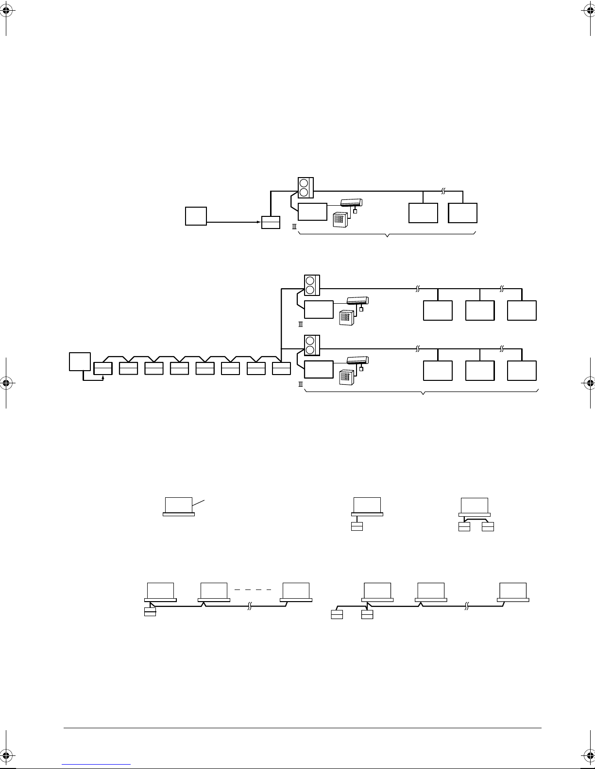
SYSTEM OVERVIEW
This central remote controller can monitor and control up to 16 “indoor unit groups”.
By using eight units of this central remote controller, maximum of 128 “indoor unit groups” can be monitored and
controlled.
Main Functions
1. Simultaneous ON/OFF control of all indoor units connected to the central remote controller.
2. Setting of operating conditions (such as ON/OFF and set temperature) of indoor units individually by “group”.
3. Monitoring of operating conditions such as operation mode and set temperature.
4. Connection of an external key system, central monitoring panel, etc. via Forced OFF input (T1, T2).
• When using one central remote controller unit
Outdoor unit
Central
monitoring
panel, etc.
Forced OFF
command
Residential central
remote controller
Group No.
1-00
D -Net Adapter
Room Type
Indoor Unit
Up to 16 indoor unit groups
Group No.
1-01
...
Group No.
1-15
• When using eight central remote controller units
Outdoor unit
Room Type
Indoor Unit
Room Type
Indoor Unit
Up to 128 indoor unit groups
Group No.
1-15
Group No.
5-15
Group No.
... ...
2-00
Group No.
... ...
6-00
Group No.
Group No.
Central monitoring
panel, etc.
Residential
central
remote
controller
Forced OFF command
(Connect Forced OFF command
to one of the 8 units.)
Group No.
1-00
D -Net Adapter
Outdoor unit
Group No.
5-00
D -Net Adapter
(The central remote controller cannot be used together with the optional remote control adaptor PCB or group
remote control adaptor.)
* An “indoor unit group” refers to one of the following:
1. One indoor unit without
remote controller
2. One indoor unit controlled by
one or two remote controllers
4-15
8-15
Without remote controller
3. Up to 16 indoor units group-controlled by one or two remote controllers
Remote
controller
* “Group control” is a setting which enables simultaneous control of multiple indoor units from a single remote
controller.
4
Indoor unit
OR
Remote
controller
Up to 16 units Up to 16 units
Two remote
controller
Remote
controller
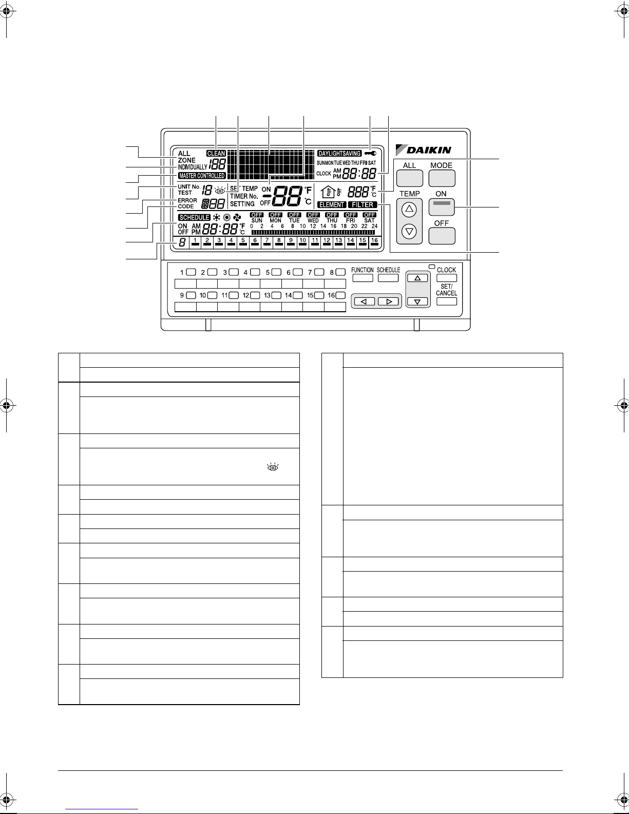
NAMES AND FUNCTIONS OF THE OPERATING SECTION
External View
(All indications are displayed in the following diagram of screen for the explanation purpose. Actual indications
displayed during operation will vary.)
12 3-3
1
2
11
3-1
3-2
14
7
9
ALL
1
This indicates that the display shows the ALL screen.
INDIVIDUALLY
This indicates that the display shows the INDIVIDU-
2
ALLY screen for the currently selected air conditioner
No.
ERROR CODE DISPLAY
When an equipment malfunction occurs, the malfunc-
3
tion UNIT No. (
3
) indications blink.
OPERATION MODE DISPLAY (Dot Matrix)
4
This section displays the operation status.
SET TEMP DISPLAY
5
This section displays the set temperature.
ON LAMP
6
This lamp lights when one or more indoor units under
control are operating.
SCHEDULE SETTING DISPLAY
7
This section displays the programmed operation
details.
KEY LOCK DISPLAY
8
This symbol appears when the key lock has been activated.
OPERATION MONITOR
9
Each box shows the No. of connected air conditioner
(group) and its operation status.
3-1
), ERROR CODE (
3-2
) and (
4 8 135
3-
10
6
12
OUTDOOR TEMP DISPLAY
In the ALL screen, this displays the outside temperature detected by the outdoor unit connected to the air
conditioner (group) with a cooling/heating selection
privilege(*) that has the smallest unit No.
In the INDIVIDUALLY screen, this displays the outside
10
temperature detected by the outdoor unit connected to
the selected air conditioner (group).
If Total Heat Exchanger is selected, outdoor temperature is not displayed.
(*An air conditioner (group) with a cooling/heating
selection privilege is a unit which allows switching of
the operation mode between cooling and heating.)
MASTER-CONTROLLED DISPLAY
This indication appears when the selected air condi-
11
tioner (group) does not have a cooling/heating selection privilege.
CLEAN SIGN
12
The FILTER and ELEMENT indications appear when
the filter and element need to be cleaned.
CLOCK DISPLAY
13
This shows the current time.
OPERATION CODE DISPLAY
This displays the operation code (prohibit remote con-
14
troller, central control priority, last button priority, etc.)
during the setting of operation details.
5

NAMES AND FUNCTIONS OF
THE OPERATING SECTION
Names of Operation Buttons
15 16
23
24
25
26
SCREENS
BUTTONS
Used to select a menu.
CLOCK BUTTON
Changes the display to the current time setting screen.
SET/CANCEL BUTTON
Enters or cancels settings.
BUTTONS
Used to set an operation schedule or current time.
17
ALL BUTTON
15
Changes the display to the ALL screen.
MODE BUTTON
16
Used to select the operation mode.
TEMP BUTTONS
17
Used to set the temperature.
ON BUTTON
18
Turns on all indoor units or individual unit (group).
OFF BUTTON
19
Stops all indoor units or individual unit (group).
20
18
19
HOW TO DISPLAY THE ALL
SCREEN
Displaying the ALL screen
(1)
[Operating Procedure]
Press the ALL button (1).
When one or more connected air conditioners (groups)
are operating, if no button is operated for 20 seconds,
the display changes to the INDIVIDUALLY screen. If all
air conditioners are in non-operation, the display does
not change to the INDIVIDUALLY screen.
INDIVIDUAL UNIT (GROUP) SELECTION BUTTONS
Changes the display to the INDIVIDUALLY screen for
20
monitoring or setting the air conditioner (group) of the
indicated No.
23
21
22
26
FUNCTION BUTTON
21
Changes the display to the Function Menu setting
screen.
SCHEDULE BUTTON
22
Changes the display to the SCHEDULE setting screen.
6
24
25
NOTE
Operate buttons while the backlights are lit.
[Screen Display]
A
B
A. The ALL screen appears, and “ALL” is indicated at
the upper left corner of the screen.
B. This section displays the operation information of
the air conditioner in operation that has the smallest unit No. in the air conditioners (groups) with
cooling/heating selection privilege.
D
C
C. This section displays the Nos. of all connected air
conditioners (groups).
The indication lights under the Nos. of air conditioners that are operating.
D. “System Down” is indicated when all air condition-
ers in the system are in non-operation.
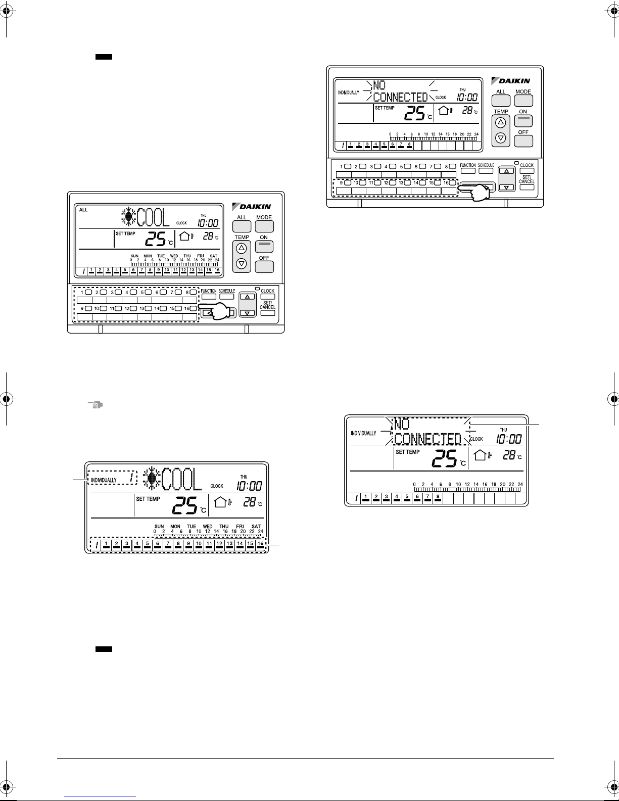
HOW TO DISPLAY THE INDIVIDUALLY SCREEN
Displaying the INDIVIDUALLY screen
(1)
[Operating Procedure]
Press one of the individual group selection buttons (1)
(1 - 16).
NOTE
Operate buttons only when the backlights are lit.
When an unconnected air conditioner
(group) is selected
(1)
[Operating Procedure]
If the No. of an unconnected air conditioner is selected
with one of the individual group selection buttons (1)
(1 - 16), the operation mode display section (dot matrix)
shows a blinking “NO CONNECTED” indication for 2
seconds.
After the indication blinks for 2 seconds, the display
returns to the air conditioner screen that was displayed
prior to the selection of the unconnected air conditioner
(group).
* In the above diagram, unconnected air conditioners
are unit Nos. 9 through 16.
[Screen Display]
A
[Screen Display]
A
A. The INDIVIDUALLY screen appears, and the No.
of the selected air conditioner is indicated at the
upper left corner of the screen.
(In the above screen, unit No. 1 is selected.)
B. This section displays the Nos. of all connected air
conditioners (groups).
The indication lights under the Nos. of air conditioners that are operating.
B
A. If the No. of an unconnected air conditioner is
selected with one of the individual group selection
buttons (1 - 16), the operation mode display section (dot matrix) shows a blinking “NO CONNECTED” indication for 2 seconds.
OPERATION
7
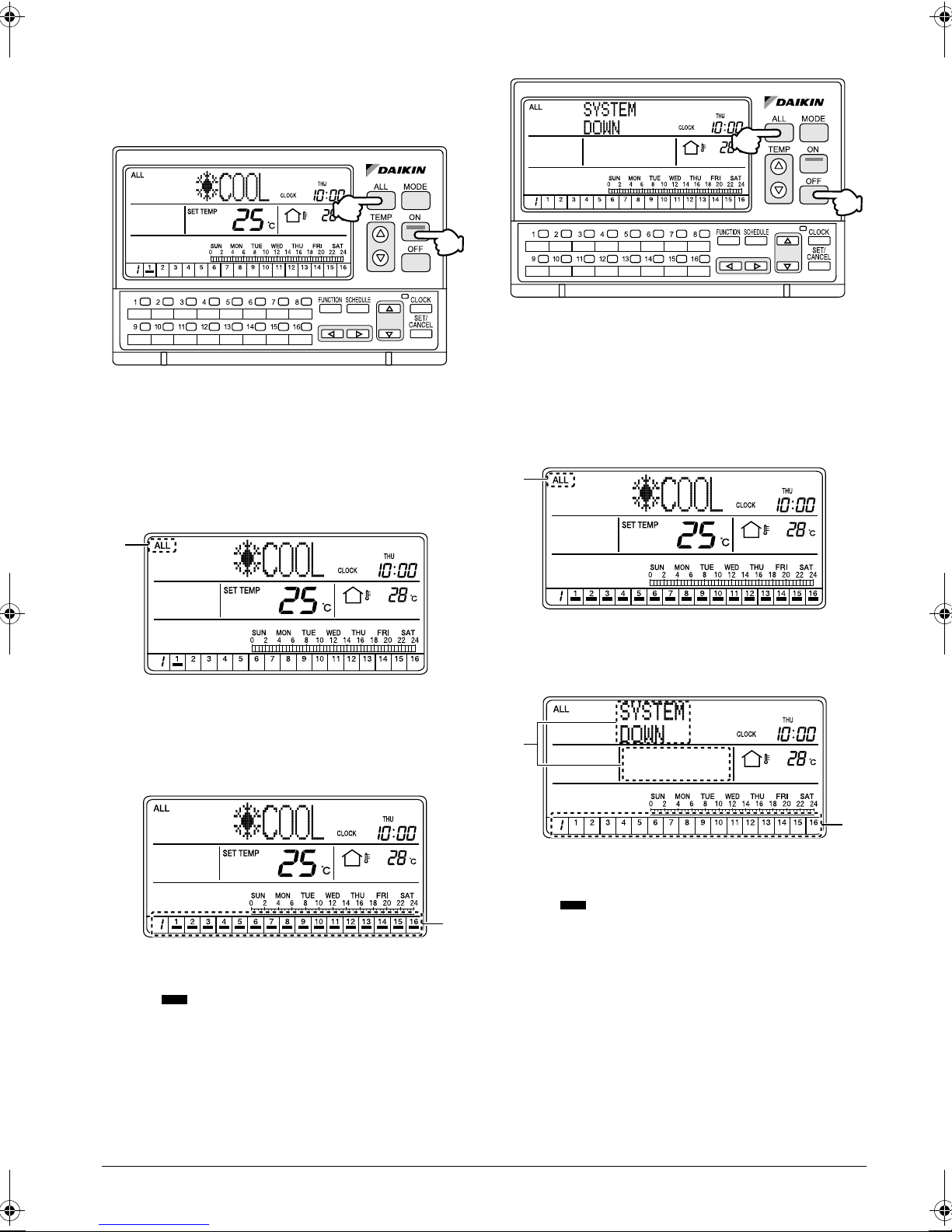
HOW TO TURN ALL UNITS ON
OR OFF SIMULTANEOUSLY
Turning on all connected units
Stopping all connected units
(1)
(1)
(2)
[Operating Procedure]
1. Press the ALL button (1) to display the ALL screen.
2. Press the ON button (2) to turn on all connected air
conditioners (groups).
[Screen Display]
A
(2)
[Operating Procedure]
1. Press the ALL button (1) to display the ALL screen.
2. Press the OFF button (2) to stop all connected air
conditioners (groups).
[Screen Display]
C
C. When the ALL button (1) is pressed, the ALL
screen appears and “ALL” is indicated at the upper
left corner of the screen.
A. When the ALL button (1) is pressed, the ALL
screen appears and “ALL” is indicated at the upper
left corner of the screen.
If no button is operated for 20 seconds, the display
changes to the INDIVIDUALLY screen.
B
B. When the ON button (2) is pressed, all connected
air conditioners (groups) start operation.
The indications appear in the operation monitor section.
E
D
D. Press the OFF button (2) to stop all connected air
conditioners (groups).
The indications in the operation monitor section disappear.
E. “SYSTEM DOWN” is indicated in the operation
mode display section (dot matrix), and the set temperature indication disappears.
8
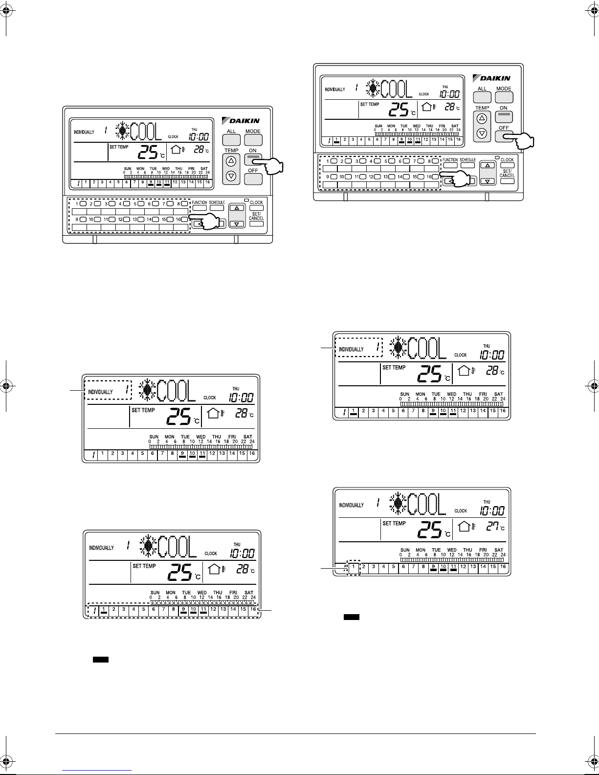
HOW TO TURN UNITS ON OR
OFF INDIVIDUALLY
Turning On specific connected air con-
ditioners
(2)
Turning Off specific connected air con-
ditioners
(2)
(1)
(1)
[Operating Procedure]
1. Select an air conditioner (group) using one of the
individual group selection buttons (1) (1 - 16) to
display the INDIVIDUALLY screen.
2. Press the ON button (2) to turn on the selected air
conditioner (group).
[Screen Display]
A
A. When one of the individual group selection buttons
(1) (1 - 16) is pressed, the INDIVIDUALLY screen
appears and the selected air conditioner No. is
shown at the upper left corner of the screen.
[Operating Procedure]
1. Select an air conditioner (group) using one of the
individual group selection buttons (1) (1 - 16) to
display the INDIVIDUALLY screen.
2. Press the OFF button (2) to turn off the selected air
conditioner (group).
[Screen Display]
C
C. When one of the individual group selection buttons
(1) (1 - 16) is pressed, the INDIVIDUALLY screen
appears and the selected air conditioner No. is
shown at the upper left corner of the screen.
B. Press the ON button (2) to turn on the selected air
conditioner (group).
The indication lights under the No. of the
selected air conditioner.
B
D
D. Press the OFF button (2) to turn off the selected air
conditioner (group).
The indication under the selected air conditioner No. in the operation monitor section disappears.
9
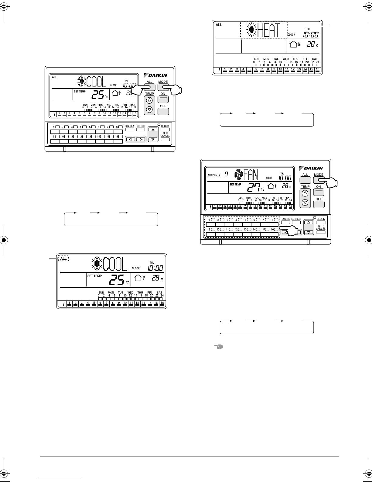
HOW TO CHANGE THE OPERATION MODE
Changing the operation mode of all
connected air conditioners
B
(1)
(2)
[Operating Procedure]
1. Press the ALL button (1) to display the ALL screen.
2. Each time the MODE button (2) is pressed, the
operation mode changes in the following
sequence.
FAN
COOL HEAT
[Screen Display]
A
B. Each time the MODE button (2) is pressed, the
operation mode of all connected air conditioners
(groups) changes in the following sequence.
FAN
COOL HEAT
Changing the operation mode of spe-
cific connected air conditioners
(2)
(1)
[Operating Procedure]
1. Select an air conditioner (group) using one of the
individual group selection buttons (1) (1 - 16) to
display the INDIVIDUALLY screen.
2. Each time the MODE button (2) is pressed, the
operation mode changes in the following
sequence.
A. When the ALL button (1) is pressed, the ALL
screen appears and “ALL” is indicated at the upper
left of the screen.
If no button is operated for 20 seconds, the display
changes to the INDIVIDUALLY screen.
10
FAN
NOTE
The operation mode cannot be changed to VENTILATION by selecting Total Heat Exchanger with one of the
individual group selection buttons (1) (1 - 16) and by
pressing the MODE button (2).
In this case, the “NO FUNCTION” indication blinks for
2 seconds in the operation mode display section (dot
matrix).
COOL HEAT
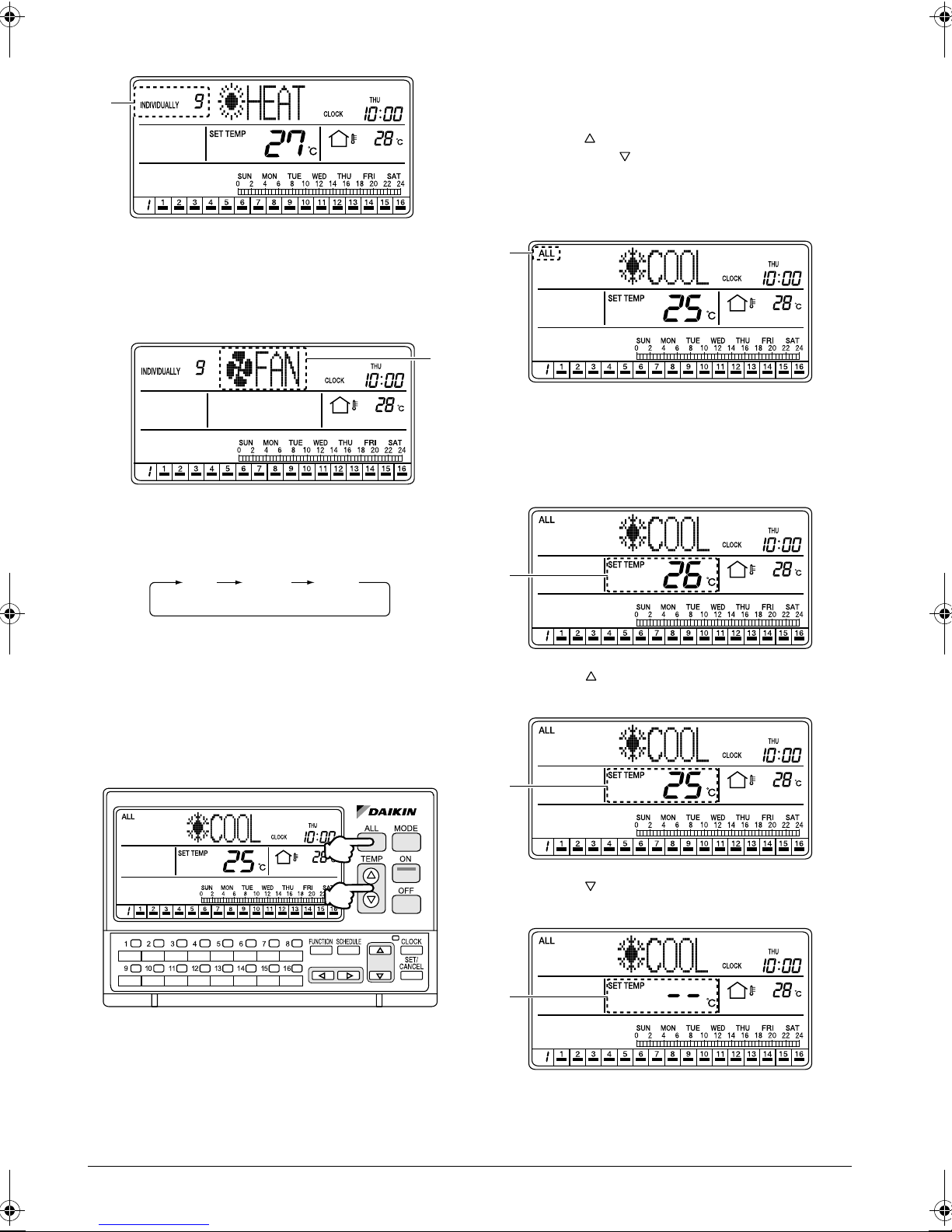
[Screen Display]
C
[Operating Procedure]
1. Press the ALL button (1) to display the ALL screen.
2. Each time one of the TEMP buttons (2) is pressed,
the set temperature changes.
Press the button to raise the set temperature by
1°C. Press the button to lower the set temperature by 1°C.
[Screen Display]
C. When the No. of an air conditioner is selected with
one of the individual group selection buttons (1)
(1 - 16), the display changes to the INDIVIDUALLY
screen and the No. of the selected air conditioner
is shown at the upper left corner of the screen.
D
D. Each time the MODE button (2) is pressed, the
operation mode of the selected air conditioner
(group) changes in the following sequence.
FAN
COOL HEAT
HOW TO ADJUST THE SET TEMPERATURE
A
A. When the ALL button (1) is pressed, the ALL
screen appears and “ALL” is indicated at the upper
left of the screen.
If no button is operated for 20 seconds, the display
changes to the INDIVIDUALLY screen.
B
B. Press the TEMP button (2) to raise the set tem-
perature by 1°C.
Adjusting the set temperature in all
connected air conditioners
(1)
(2)
C
C. Press the TEMP button (2) to lower the set tem-
perature by 1°C.
D
11
D. If you do not want to set the temperature in all con-
nected air conditioners (groups), set the set temperature to “--”.
The “--” indication appears after pressing the
button to raise the set temperature to the highest
temperature setting and pressing the button one
more time.
The “--” indication also appears after pressing the
button to set the lowest temperature setting and
pressing the button one more time.
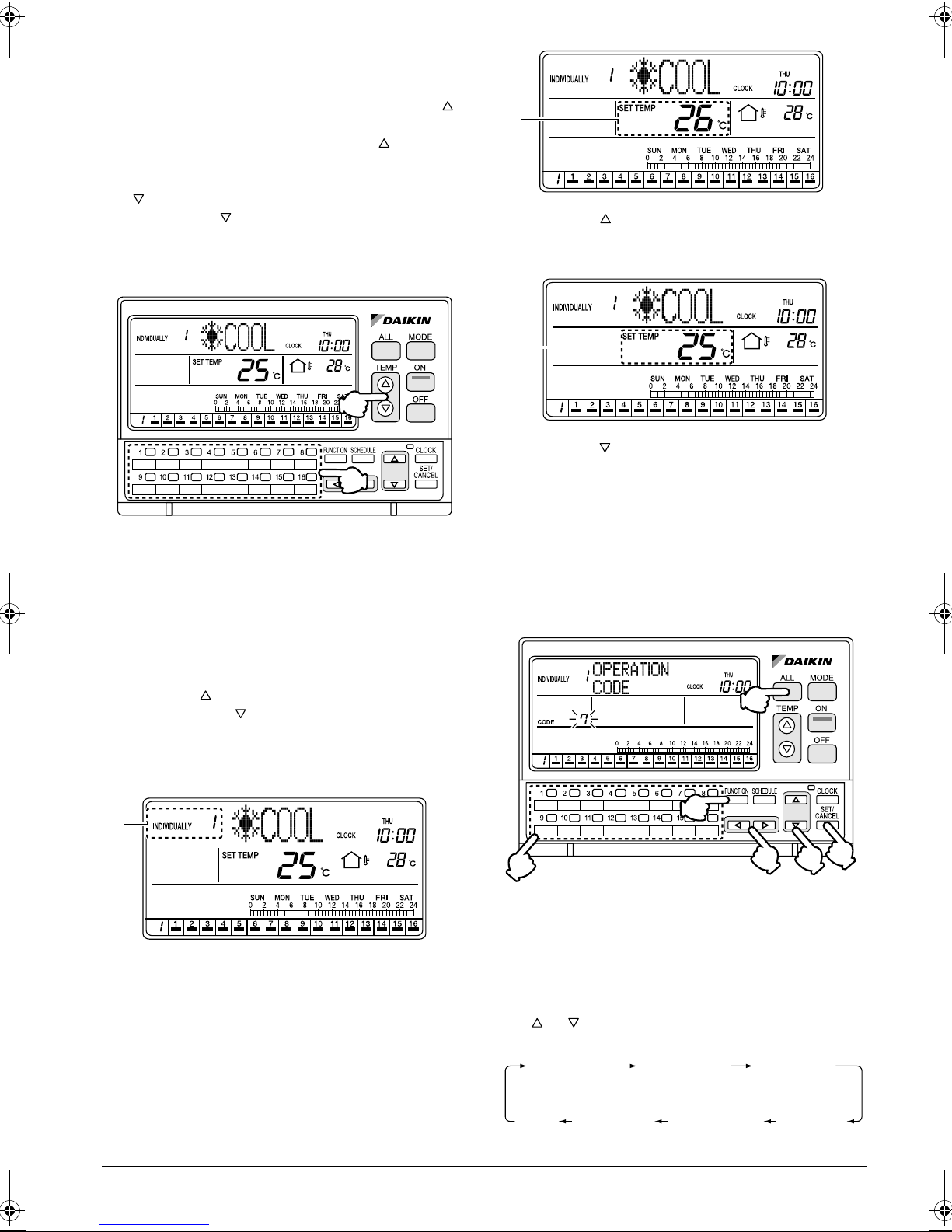
Adjusting the set temperature in specific connected air conditioners
(2)
(1)
F
F. Press the TEMP button (2) to raise the set tem-
perature in the selected air conditioner (group) by
1°C.
G
G. Press the TEMP button (2) to lower the set tem-
perature in the selected air conditioner (group) by
1°C.
FUNCTIONS
[Operating Procedure]
1. Select an air conditioner (group) to be set by using
one of the individual group selection buttons (1)
(1 - 16).
2. Each time one of the TEMP buttons (2) is pressed,
the set temperature in the selected air conditioner
(group) changes.
Press the button to raise the set temperature by
1°C. Press the button to lower the set temperature by 1°C.
[Screen Display]
E
E. This section displays the No. of the air conditioner
selected with one of the individual group selection
buttons (1) (1 - 16).
OPERATION CODE
Setting Prohibit Remote Control, Cen-
tral Control Priority, etc.
(5)
(1)
(2)
(3)
(6)
(4)
[Operating Procedure]
1. While the ALL or INDIVIDUALLY screen is dis-
played, press the FUNCTION button (1) once.
2. The Function Menu appears.
The Function Menu changes as follows when the
or button (2) is pressed.
OPERATION
CODE
RESET
FILTER SIGN
OUTDOOR
TEMP
DISPLAY
12
KEY
LOCK
CONTRAST
SET DAYLIGHT
SAVING TIME
DAYLIGHT
SAVING
3. Select OPERATION CODE to display the operation code setting screen.
4. Using the ALL button (5) or one of the individual
group selection buttons (6) (1 - 16), select the air
conditioner (group) in which an operation code is
to be set.
5. Press the or button (4) to set an operation
code.
Press the button to increment the operation
code. Press the button to decrement the operation code.
6. Press the SET/CANCEL button (3) once to complete the operation code setting procedure.
The operation code indication blinks for 3 seconds
and changes to constant On. Then, the display
returns to the ALL screen if the setting was made
in the ALL screen, or to the INDIVIDUALLY screen
if the setting was made in the INDIVIDUALLY
screen.
* The operation code entered last takes prece-
dence. Therefore, if the setting is made in the
ALL screen after the setting is entered in the
INDIVIDUALLY screen, the setting made in the
ALL screen will be applied.
NOTE
1. Operate buttons while the backlights are lit.
2. In steps 2 through 5, if no button is operated for
1 minute, the display returns to the ALL screen
when the setting was made in the ALL screen, or to
the INDIVIDUALLY screen if the setting was made
in the INDIVIDUALLY screen.
In the above-mentioned case, the setting being
entered will not be applied.
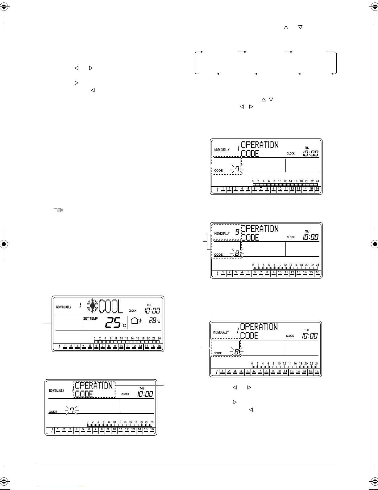
B. The Function Menu appears. The Function Menu
changes as follows when the or button (2) is
pressed.
OPERATION
CODE
KEY
LOCK
CONTRAST
If no button is pressed for 2 seconds while the display shows screen B to screen E on page 13, a
guidance message, “ BUTTONS: CHANGE
FUNCTION, BUTTONS: CHANGE OPERATION CODE, SET/CANCEL BUTTON: SET,”
appears in the operation mode display section (dot
matrix).
RESET
FILTER SIGN
SET DAYLIGHT
SAVING TIME
OUTDOOR
TEMP
DISPLAY
DAYLIGHT
SAVING
C
C. Select OPERATION CODE to display the opera-
tion code setting screen.
D
[Screen Display]
A
A. While the ALL or INDIVIDUALLY screen is dis-
played, press the FUNCTION button (1) once.
B
D. Using the ALL button (5) or one of the individual
group selection buttons (6) (1 - 16), select the air
conditioner (group) in which an operation code is
to be set.
E
E. Press the or button (4) to set an operation
code.
Press the button to increment the operation
code. Press the button to decrement the operation code.
13
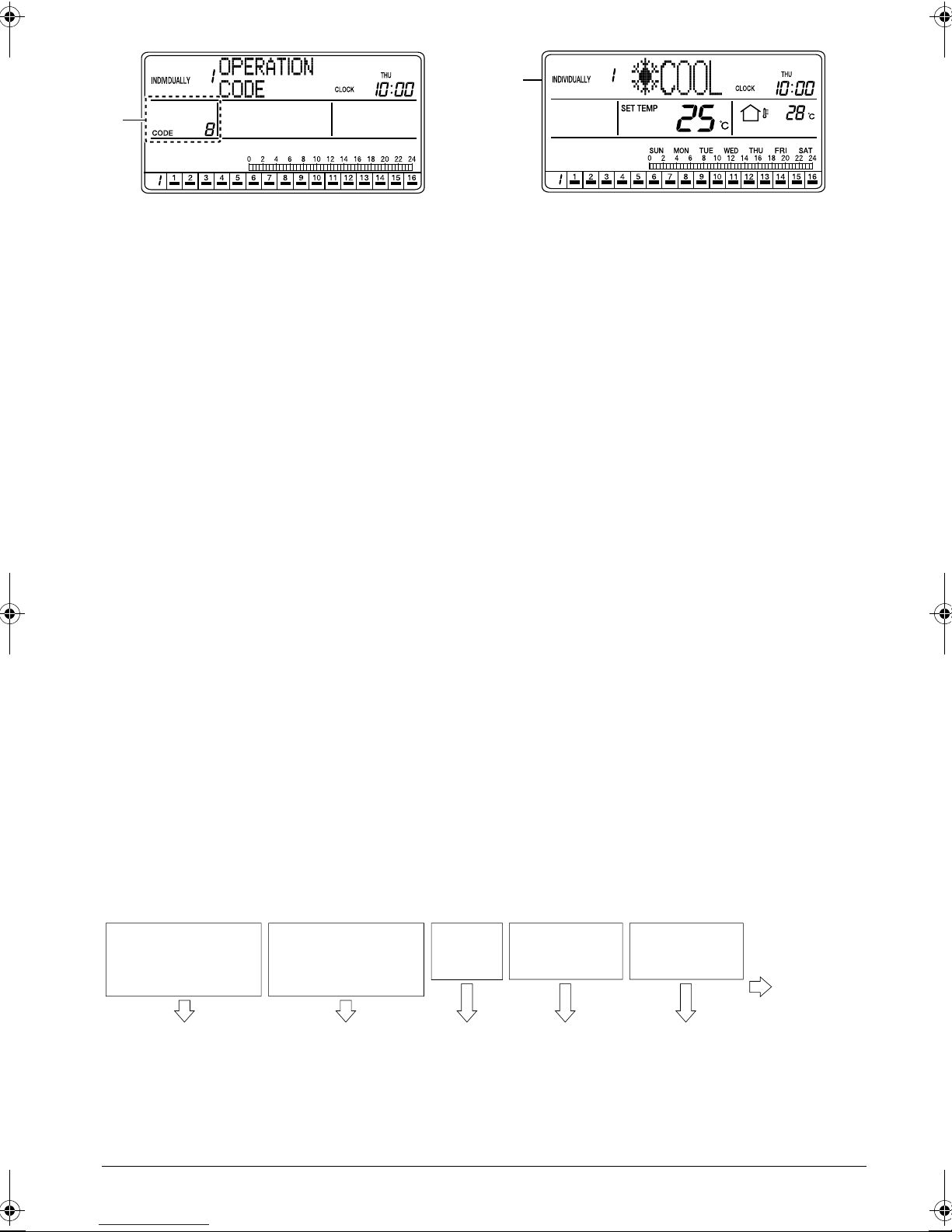
G
F
F. Press the SET/CANCEL button (3) once to com-
plete the operation code setting procedure.
The operation code indication blinks for 3 seconds
and changes to constantly On. Then, the display
returns to the ALL screen if the setting was made
in the ALL screen, or to the INDIVIDUALLY screen
if the setting was made in the INDIVIDUALLY
screen.
G. The operation code indication blinks for 3 seconds
and changes to constantly On. Then, the display
returns to the ALL screen if the setting was made
in the ALL screen, or to the INDIVIDUALLY screen
if the setting was made in the INDIVIDUALLY
screen.
* Regarding the details of operation codes, refer to
“Details of Operation Codes” on the following
page.
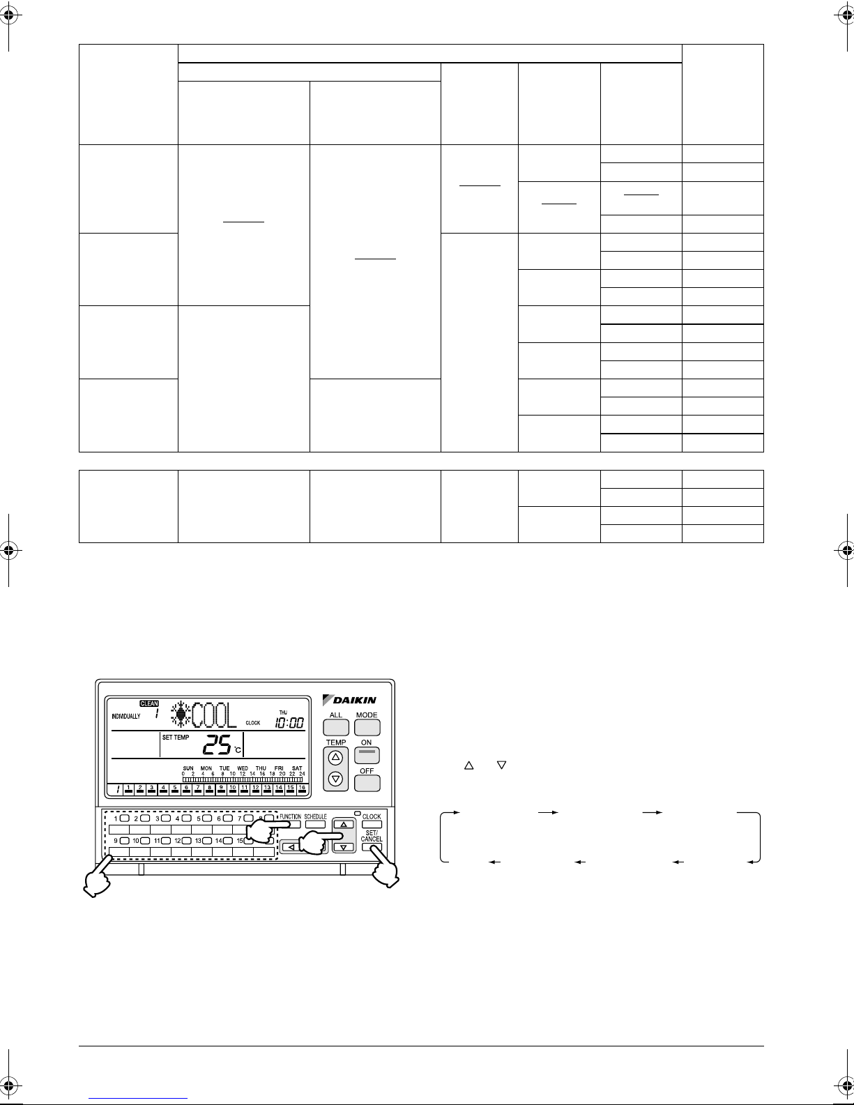
[Details of Operation Codes]
Twenty modes, which are combinations of one of the following operation control modes and the remote ON/OFF, set
temperature and operation mode that can be performed with a remote controller, can be set in operation codes 0
through 19. They can be also displayed on the screen.
• Prohibit Remote Controller ............................. To enable ON/OFF control only from the central remote controller.
(Remote controllers cannot be used for ON/OFF control.)
• Permit Only OFF from Remote Controller...... To enable ON control only from the central remote controller and
allows the use of remote controllers for OFF control only.
(The central remote controller can be also used for OFF control.)
• Central Controller Priority ............................... To enable ON control only from the central remote controller and
allows the use of remote controllers for ON/OFF control of units
that were turned on by the central remote controller.
• Last Button Priority......................................... To enable ON/OFF control from both the central remote controller
and remote controllers.
• Remote Controller Permit Timer..................... To enable ON/OFF control from remote controllers during the
SCHEDULE timer operation, and disallow the central remote controller to turn on units at the programmed ON time.
(Use of remote controllers is permitted at the programmed ON
time, and use of remote controllers is prohibited at the programmed OFF time. Air conditioners turn off at the programmed
OFF time.)
How to select an operation code
• When using a remote controller, select either permit or prohibit for each of the ON/OFF, set temperature and
operation mode settings, and set the operation code indicated in the rightmost column in the table below.
(Examples)
ON from remote
controller
(All ON from central
remote controller)
Prohibit Prohibit Prohibit Permit Permit
ON from remote
controller
(All OFF from central
remote controller)
14
OFF from
remote
controller
Temperature
adjustment from
remote controller
Operation mode
setting from
remote controller
Operation
code is “1”
Control mode
Prohibit Remote
Controller
Per mit Only
OFF from
Remote
Controller
Central Control
Priority
Last Button
Priority
All ON by central
remote controller,
individual ON, ON by
timer
Prohibit
(Examples)
Per mit
Operation performed from remote controller
ON
All OFF by central
remote controller,
individual OFF, OFF
by timer
Prohibit
(Examples)
Per mit
OFF
Prohibit
(Examples)
Per mit
Temperature
setting
Prohibit
Permit
(Examples)
Prohibit
Permit
Prohibit
Permit
Prohibit
Permit
Operation
mode setting
Per mit 0
Prohibit 10
Per mit
(Examples)
Prohibit 11
Per mit 2
Prohibit 12
Per mit 3
Prohibit 13
Per mit 4
Prohibit 14
Per mit 5
Prohibit 15
Per mit 6
Prohibit 16
Per mit 7
Prohibit 17
1 (Examples)
Operation
Code
Remote
Controller
Per mit Tim er
Per mit
(When timer ON)
Prohibit
(When timer OFF)
Prohibit
Per mit
Permit
Per mit 8
Prohibit 18
Per mit 9
Prohibit 19
NOTE)When remote controllers are not used, do not select “Remote Controller Permit Timer.”
Selecting this setting disallows the use of the timer for air conditioner operation.
RESET FILTER SIGN
After cleaning the filter, reset the Filter sign by using
RESET FILTER SIGN in the Function Menu.
Turning off the Filter sign
[Operating Procedure]
1. While the ALL or INDIVIDUALLY screen is dis-
played, press the FUNCTION button (1) once.
2. The Function Menu appears.
The Function Menu changes as follows when the
or button (2) is pressed.
(1)
(2)
(3)
(4)
[CLEAN Signs]
When the filter or element needs cleaning, the Filter or
Element sign appears on the multi-language central
remote controller.
(* For details, refer to “CLEAN SIGN” on page 5.)
OPERATION
CODE
KEY
LOCK
3.
CONTRAST
In the Reset Filter Sign screen, select the air conditioner for which the filter sign is to be reset by using
one of the individual group selection buttons (3).
4. Press the SET/CANCEL button
ter sign.
RESET
FILTER SIGN
SET DAYLIGHT
SAVING TIME
OUTDOOR
TEMP
DISPLAY
DAYLIGHT
SAVING
(4)
to reset the Fil-
15
 Loading...