

Daikin DCS302C71 Operation Manual
OPERATION MANUAL
CENTRAL REMOTE CONTROL-
MODELS
DCS302C71
Read these instructions carefully before installation.
Keep this manual in a handy place for future reference.
This manual should be left with the equipment owner.

1 English
BEFORE USE ..................................................... 3
GENERAL DESCRIPTION OF SYSTEM .............. 3
SAFETY CONSIDERATIONS ....................... 4
FEATURES AND FUNCTIONS .................... 6
NAMES AND FUNCTIONS OF THE
OPERATING SECTION................................... 7
OPERATION........................................................ 8
Individual screen, all screen,
zone screen (Fig. 3) .............................................. 8
Batch operation and stop method ......................... 9
Batch operation and batch stopping....................... 9
Group operation and stop method.......................... 9
Registering zones................................................... 9
Zone operation and stop method ......................... 10
Changing the fan direction and fan strength ........ 10
Changing the ventilation mode and ventilation
strength ................................................................ 11
Timer Number Setting .......................................... 11
Setting the Operation Code.................................. 12
OPERATION MODE ....................................... 13
SETTING OPERATION MODE............................ 16
GROUP MONITORING........................................ 17
ERROR DIAGNOSING FUNCTION .................... 17
SETTING MASTER REMOTE
CONTROLLER..................................................... 17
DISPLAY OF TIME TO CLEAN............................ 18
INSTALLATION TABLE ......................... 19
OPTIONAL ACCESSORIES................... 20
DOUBLE CENTRAL REMOTE
CONTROLLERS .............................................. 20
SPECIFICATIONS........................................... 21
Specifications ...................................................... 21
Outline drawings .................................................. 21

1 English
BEFORE USE
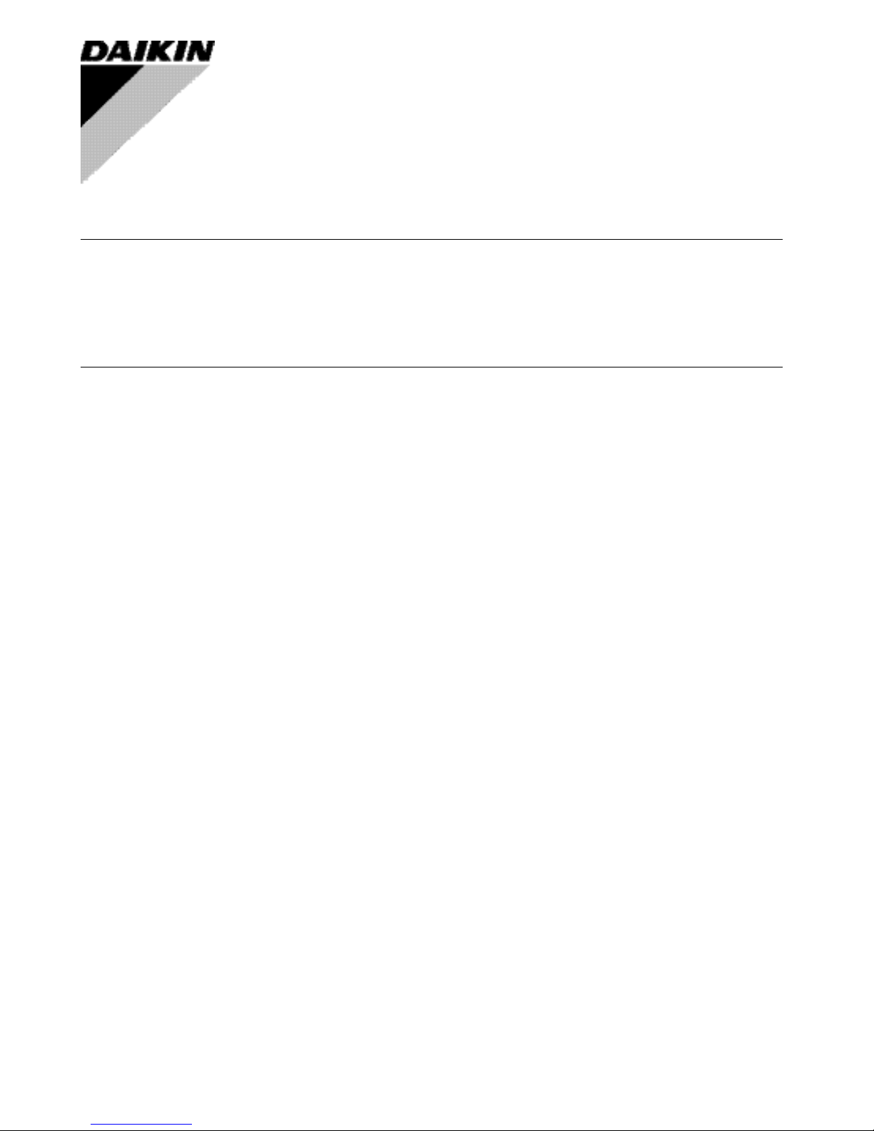
n GENERAL DESCRIPTION OF SYSTEM
This central remote controller can monitor and control up to 64 indoor unit groups.
Using two central remote controllers allows monitoring and controlling of up to 128 indoor unit groups.
Main Functions
1. Batch starting and stopping of indoor units connected to the central remote controller.
2. Handling of operation settings such as start/stop, timer operation, remote controller prohibition/permission, etc.,
and operation status settings such as temperature.
3. Operation status monitoring of operation mode, set temperature, etc.
4. Can be connected to an external central monitor panel and key system using the forced stop input
(non-voltage a connector).
• When using 1 central remote controller
• When using 2 central remote controllers
(The central remote controller and the separately sold remote control adapter circuit board or group remote control adapter cannot be used together.)
∗ GROUP OF INDOOR UNIT refers to the below.
1. A single indoor unit without remote controller
English 2
∗ Zone control from the central remote controller
Zone control is available from the central remote controller. With it, it is possible to make unified settings for multiple groups, so setting operations are greatly simplified.
• Any setting you make within a given zone will apply to all groups in the said zone.
• A maximum of 64 zones can be set from a single central remote controller.
(Each zone contains a maximum of 64 groups.)
• Zones can be set randomly from the central remote controller.
SAFETY CONSIDERATIONS
Please read these “SAFETY CONSIDERATIONS”
carefully before installing air conditioning equipment
and be sure to install it correctly.
After completing the installation, make sure that the
unit operates properly during the start-up operation.
Please instruct the customer on how to operate the unit
and keep it maintained.
Also, inform customers that they should store this installation
manual along with the operation manual for future reference.
This air conditioner comes under the term “appliances
not accessible to the general public”.
Meaning of warning, caution and note symbols.
WARNING
....Indicates a potentially hazardous sit-
uation which, if not avoided, could
result in death or serious injury.
CAUTION .... Indicates a potentially hazardous
situation which, if not avoided, may
result in minor or moderate injury.
It may also be used to alert against
unsafe practices.
NOTE........... Indicates situation that may result
in equipment or property-damageonly accidents.
Keep these warning sheets handy so that you can
refer to them if needed.
Also, if this equipment is transferred to a new user, make
sure to hand over this operation manual to the new user.
WARNING
In order to avoid electric shock, fire or injury, or if
you detect any abnormality such as smell of fire, turn
off power and call your dealer for instructions.
Ask your dealer for installation of the air conditioner.
Incomplete installation performed by yourself may
result in a water leakage, electric shock, and fire.
Ask your dealer for improvement, repair, and maintenance.
Incomplete improvement, repair, and maintenance may
result in a water leakage, electric shock, and fire.
Improper installation or attachment of equipment or
accessories could result in electric shock, short-circuit,
leaks, fire or other damage to the equipment. Be sure only
to use accessories made by Daikin which are specifically
designed for use with the equipment and have them
installed by a professional.
Ask your dealer to move and reinstall the air conditioner or the remote controller.
Incomplete installation may result in a water leakage,
electric shock, and fire.
Never let the indoor unit or the remote controller get wet.
It may cause an electric shock or a fire.
Never use flammable spray such as hair spray,
lacquer or paint near the unit.
It may cause a fire.
Never replace a fuse with that of wrong ampere
ratings or other wires when a fuse blows out.
Use of wire or copper wire may cause the unit to
break down or cause a fire.
Never inspect or service the unit by yourself.
Ask a qualified service person to perform this work.
Cut off all electric waves before maintenance.
Do not wash the air conditioner or the remote
controller with excessive water.
Electric shock or fire may result.
Do not install the air conditioner or the remote controller
at any place where flammable gas may leak out.
If the gas leaks out and stays around the air conditioner, a fire may break out.
Do not touch the switch with wet fingers.
Touching a switch with wet fingers can cause electric shock.
3 English
Fig. 1
Fig. 3
Fig. 2
Fig. 4
4 English
Fig. 6
Fig. 5
Fig. 8
Fig. 7
5 English
CAUTION
After a long use, check the unit stand and fitting
for damage.
If they are left in a damaged condition, the unit may
fall and result in injury.
Do not allow a child to mount on the unit or avoid
placing any object on it.
Falling or tumbling may result in injury.
Do not let children play on and around the unit.
If they touch the unit carelessly, it may result in injury.
Do not place a flower vase and anything containing water.
Water may enter the unit, causing an electric shock or fire.
Never touch the internal parts of the controller.
Do not remove the front panel. Some parts inside are dangerous to touch, and a machine trouble may happen.
For checking and adjusting the internal parts, contact
your dealer.
Avoid placing the controller in a spot splashed
with water.
Water coming inside the machine may cause an electric
leak or may damage the internal electronic parts.
Do not operate the air conditioner when using a
room fumigation - type insecticide.
Failure to observe could cause the chemicals to become
deposited in the unit, which could endanger the health of
those who are hypersensitive to chemicals.
Safely dispose of the packing materials.
Packing materials, such as nails and other metal or
wooden parts, may cause stabs or other injuries.
Tear apart and throw away plastic packaging bags
so that children will not play with them. If children
play with a plastic bag which was not torn apart, they
face the risk of suffocation.
Do not turn off the power immediately after stopping operation.
Always wait at least five minutes before turning off the
power. Otherwise, water leakage and trouble may occur.
The appliance is not intended for use by young
children or infirm persons without supervision.
The remote controller should be installed in
such away that children cannot play with it.
NOTE
Never press the button of the remote controller
with a hard, pointed object.
The remote controller may be damaged.
Never pull or twist the electric wire of the remote
controller.
It may cause the unit to malfunction.
Do not place the controller exposed to direct sunlight.
The LCD display may get discolored, failing to display the data.
Do not wipe the controller operation panel with
benzine, thinner, chemical dustcloth, etc.
The panel may get discolored or the coating peeled
off. If it is heavily dirty, soak a cloth in water-diluted
neutral detergent, squeeze it well and wipe the panel
clean. And wipe it with another dry cloth.
Dismantling of the unit, treatment of the refrigerant, oil and eventual other parts, should be done
in accordance with the relevant local and
national regulations.
CONTENTS
BEFORE USE ..................................................... 1
GENERAL DESCRIPTION OF SYSTEM .............. 1
SAFETY CONSIDERATIONS ....................... 2
FEATURES AND FUNCTIONS .................... 6
NAMES AND FUNCTIONS OF THE
OPERATING SECTION .................................. 7
OPERATION........................................................ 8
Individual screen, all screen, zone screen ............. 8
Batch operation and stop method ......................... 9
Group operation and stop method.......................... 9
Registering zones................................................... 9
Zone operation and stop method ......................... 10
Changing the fan direction and fan strength ........ 11
Changing the ventilation mode and
ventilation strength .............................................. 11
Timer Number Setting ......................................... 11
Setting the Operation Code.................................. 12
OPERATION MODE ........................................ 13
Setting operation mode .........................................16
Group monitoring ..................................................16
Error diagnosing function .....................................17
Setting master remote controller ..........................20
Display of time to clean .........................................21
INSTALLATION TABLE ................................ 22
OPTIONAL ACCESSORIES......................... 23
DOUBLE CENTRAL REMOTE
CONTROLLERS ............................................... 23
SPECIFICATIONS............................................ 24
Specifications .......................................................24
Outline drawings ..................................................24
Fig. 1, 2, 3, 4...............................................................3
Fig. 5, 6, 7, 8...............................................................4
Fig. 9, 10, 11, 12.......................................................25
Fig. 13, 14, 15, 16.....................................................26

English 6
FEATURES AND FUNCTIONS
• Room air conditioners and multi-purpose air conditioners may also be connected by using separately-sold
adapter boards.
This may limit functionality, so consult the manuals that come with each adapter board.
7 English
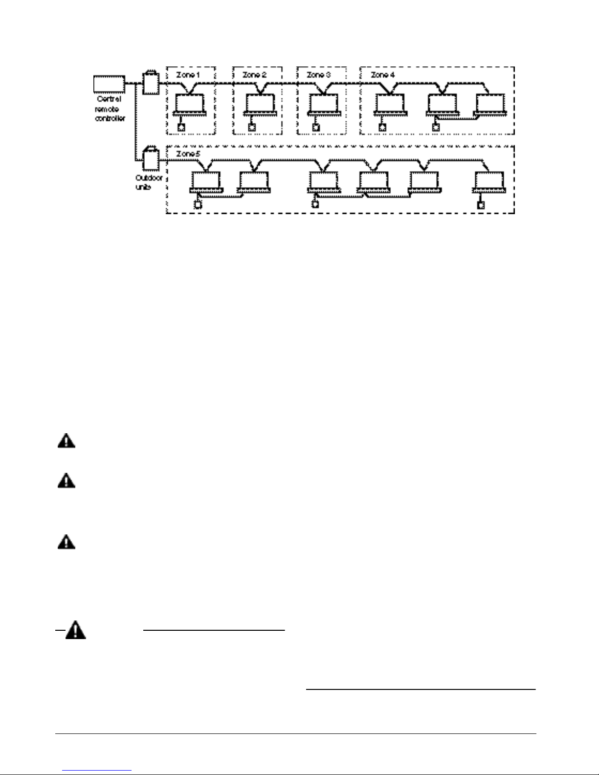
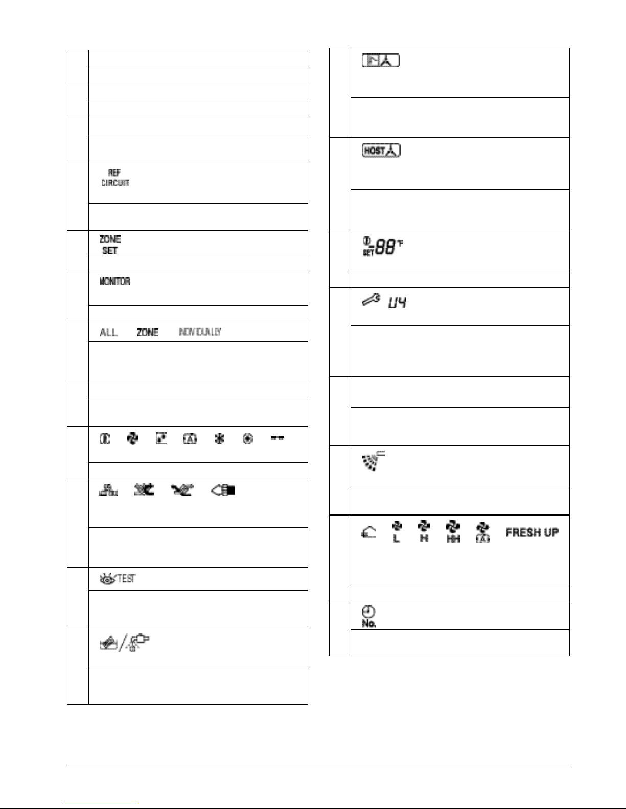
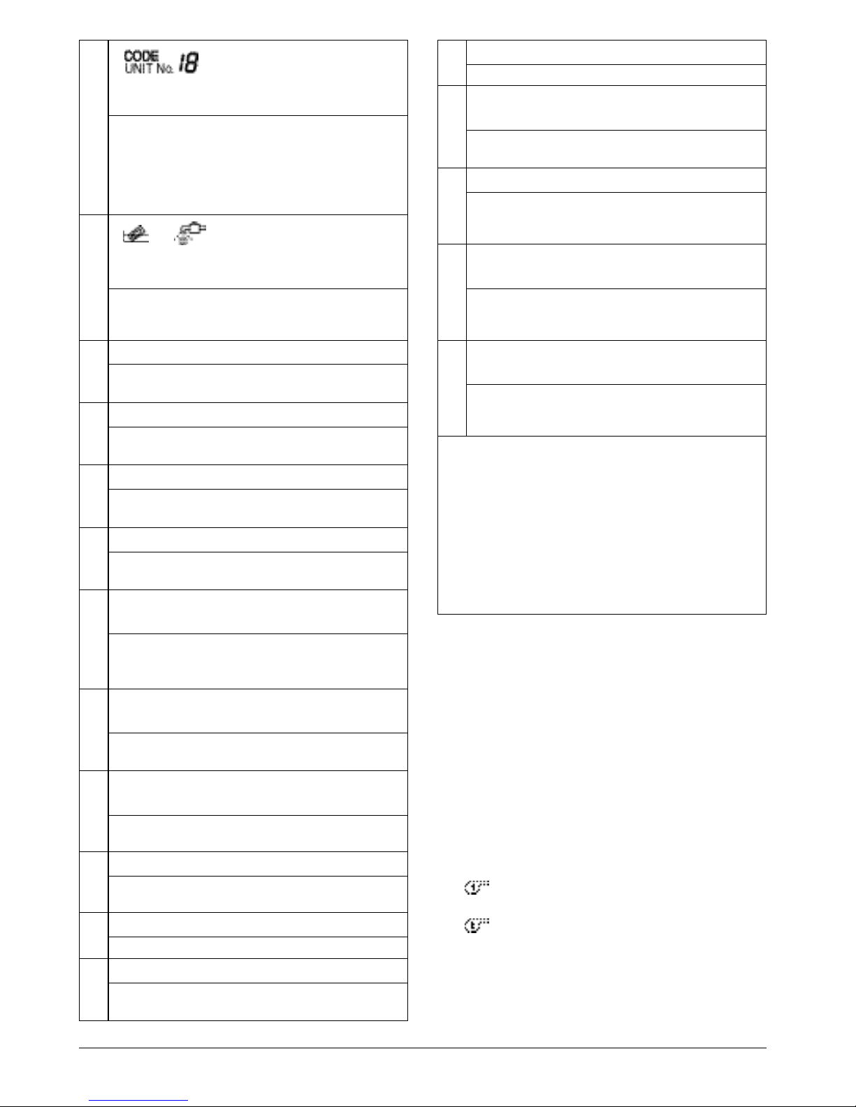
NAMES AND FUNCTIONS OF THE OPERATING SECTION (Fig. 1, 2)
1
UNIFIED OPERATION BUTTON
Press to operate all indoor units.
2
UNIFIED STOP BUTTON
Press to stop all indoor units.
3
OPERATION LAMP (RED)
Lit white any of the indoor units under control is
in operation.
4
“” DISPLAY (REFRIGERANT
SYSTEM DISPLAY)
This indication in the square is lit while the
refrigerant system is being displayed.
5
“” DISPLAY (ZONE SETTING)
The lamp is lit while setting zones.
6
“” DISPLAY (OPERATION
MONITOR)
The lamp is lit while operation is being monitored.
7
“” “” “” DISPLAY
The status displays indicates either batch
functions or which zone or individual unit
(or group) are being used.
8
OPERATION MONITOR
Each square displays the state corresponding to
each group.
9
“” “” “” “” “” “” “”
DISPLAY (OPERATION MODE)
Displays operating state.
10
“” “” “” “” DISPLAY
(VENTILATION CLEANING DISPLAY)
This is displayed when a Ventiair total enthalpy
heat exchanger unit or other such unit is
connected.
11
“”
DISPLAY (INSPECTION/TEST)
Pressing the maintenance/test run button
(for service) displays this. This button should not
normally be used.
12
“”
DISPLAY (TIME TO
CLEAN)
It lights up when any individual unit (group) has
reached the time for the filter or element to be
cleaned.
13
“”
DISPLAY (COOLING/HEATING SELECTION PRIVILEGE NOT
SHOWN)
For zones or individual units (groups) for which
this is displayed, cooling and heating cannot be
selected.
14
“” DISPLAY (UNDER HOST
COMPUTER INTEGRATED CONTROL)
While this display is lit up, no settings can be
made. It lights up when the upper central
machines are present on the same air
conditioning network.
15
“” DISPLAY
(PRESET TEMPERATURE)
Displays the preset temperature.
16
“” DISPLAY (MALFUNCTION CODE)
This displays (flashes) the content of errors
when an error failure has occurred.
In maintenance mode, it displays the latest error
content.
17
“NOT AVAILABLE” DISPLAY
(NO FUNCTION DISPLAY)
If a function is not available in the indoor unit
even if the button is pressed, “NOT AVAILABLE” is may be displayed for a few seconds.
18
“” DISPLAY
(FAN DIRECTION SWING DISPLAY)
This displays whether the fan direction is fixed
or set to swing.
19
“” “” “” “” “” “”
DISPLAY (VENTILATION
STRENGTH/SET FAN STRENGTH
DISPLAY)
This displays the set fan strength.
20
“” DISPLAY (TIME NO.)
Displays the operation timer No. when used in
conjunction with the schedule timer.
English 8
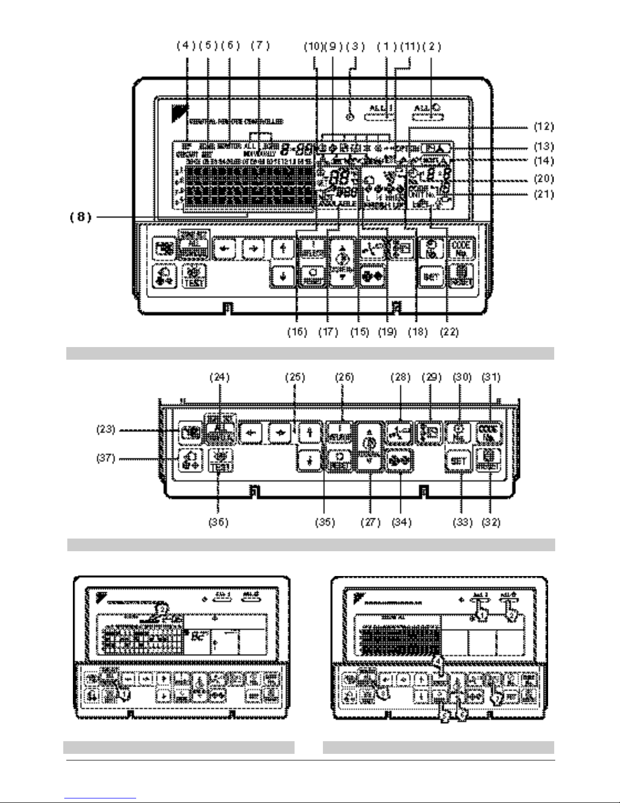
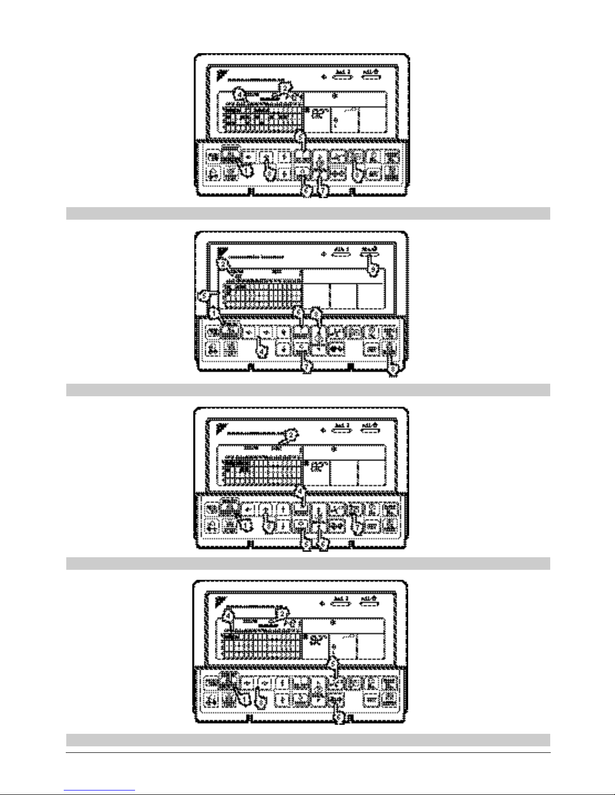
OPERATION
n Individual screen, all screen,
zone screen (Fig. 3)
This controller can perform operations in the individual
screen, all screen, or zone screen.
• Individual screen The individual screen is used
when performing group operations.
• All screen The all screen is used when per-
forming operations for all units at
once.
• Zone screen The zone screen is used when
performing zone operations.
1. Select the screen by pressing the
“ALL/INDIVIDUAL” button.
Every time the “ALL/INDIVIDUAL” button is
pressed, the selection scrolls through INDIVIDUAL
→ ALL → ZONE.
If nothing is done in the all or zone screens for one
minute, it automatically goes to the individual
screen.
21
“” DISPLAY (OPERATION
CODE AND UNIT NUMBER DISPLAY)
The method of operation (remote controller
prohibited, central operation priority after-press
operation priority, etc.) is displayed by the
corresponding code.
This displays the numbers of any indoor units
which have stopped due to an error.
22
“” “” DISPLAY (TIME TO
CLEAN AIR CLEANER ELEMENT/
TIME TO CLEAN AIR FILTER)
Displayed to notify the user it is time to clean the
air filter or air cleaner element of the group
displayed.
23
VENTILATION MODE BUTTON
This is pressed to switch the ventilation mode of
the total enthalpy heat exchanger.
24
ALL/INDIVIDUAL BUTTON
Pressing this button scrolls through the “all
screen”, “zone screen”, and “individual screen”.
25
ARROW KEY BUTTON
This button is pressed when calling an individual
indoor unit or a zone.
26
ON/OFF BUTTON
Starts and stops ALL, ZONE, and INDIVIDUAL
units.
27
TEMPERATURE ADJUSTMENT
BUTTON (ZONE NUMBER BUTTON)
This button is pressed when setting the
temperature. Select the zone number if any
zones have been registered.
28
FAN DIRECTION ADJUSTMENT
BUTTON
This button is pressed when setting the fan
direction to “fixed” or “swing”.
29
OPERATION MODE SELECTOR
BUTTON
This sets the operation mode. The dry setting
cannot be done.
30
TIME NO. BUTTON
Selects time No. (Use in conjunction with the
schedule timer only).
31
CONTROL MODE BUTTON
Selects control mode.
32
FILTER SIGN RESET BUTTON
This button is pressed to erase the “clean filter”
display after cleaning or replacement.
33
SET BUTTON
Sets control mode and time No.
34
FAN STRENGTH ADJUSTMENT
BUTTON
Pressing this button scrolls through “weak”,
“strong”, and “fast”.
35
ZONE SETTING BUTTON
Zone registration mode can be turned on and off
by pressing the start and stop buttons simultaneously for at least four seconds.
36
INSPECTION/TEST RUN BUTTON
(FOR SERVICE)
Pressing this button scrolls through “inspection”,
“test run”, and “system display”.
This button is not normally used.
37
VENTILATION STRENGTH
ADJUSTMENT BUTTON
This button is pressed to switch the ventilation
strength (“fresh up”) of the total enthalpy heat
exchanger.
(Notes)
1. Please note that all the displays in the figure
appear for explanation purposes or when the
cover is open.
2. If the unit is used in conjunction with other optional
central controllers, the OPERATION LAMP of the
unit that is not under operation control may light
up and go out a few minutes behind schedule.
This shows that the signal is being exchanged,
and does not indicate any failure.
 Loading...