

Daikin BRC1C71, BRC2A71, DCS302C71, DCS301C71, DST301BA61 Engineering Data
...

EDUS39-605A-C
Controls 1
Controls
1. Control Systems..........................................................................................2
2. Control Devices...........................................................................................3
2.1 BRC1C71 Wired Remote Controller............................................................. 3
2.2 BRC4C / 7C / 7E Wireless Remote Controller / Receiver .......................... 11
2.3 BRC2A71 Simplified Remote Controller..................................................... 13
2.4 DCS302C71 Central Remote Controller .................................................... 16
2.5 DCS301C71 Unified ON/OFF Controller.................................................... 40
2.6 DST301BA61 Schedule Timer ................................................................... 48
2.7 BRC1D71 7-Day Programmable Controller ............................................. 55
2.8 DCS601C71 intelligent Touch Controller ................................................... 62
3. Adaptors....................................................................................................74
3.1 KRCS01-1 Remote Sensor ........................................................................ 74
3.2 DTA104A 53/ 61/ 62 Required Outdoor Unit External Control Adaptor .. 75
3.3 DTA109A51 DIII NET Expander Adaptor ................................................... 77
3.4 KRP1B71 / 72 / 73 Adaptor for wiring ........................................................ 80
3.5 KRP4A71 / 72 / 73 / 74 Wiring Adaptor for Electrical Appendices ............ 82
3.6 DCS302A72 Unification Adaptor for Computerized Control....................... 87
Control Systems EDUS39-605
2 Controls
1. Control Systems
Optional Accessories of Operation Control System
C:3D043022C
Notes:
1. Installation box (No.4) is necessary for each adaptor marked with an asterisk. 2. LONWORKS is a registered trade mark of Echelon Corporation.
Building management system
Note:
1.BACnet® is a registered trademark of American Society of Heating, Refrigerating, and Air-Conditioning Engineers (ASHRAE).
2.LON WORKS is a registered trademark of Echelon Corporation.
No.
FXFQ~MVJU FXSQ~MVJU FXMQ~MVJU FXAQ~MVJU
FXLQ~MVJU
FXNQ~MVJU
FXHQ~MVJU FXDQ~MVJU
Item Type
1 Remote controller
Wireless
BRC7C812 BRC4C82 BRC7E818 — BRC7E83 BRC4C82
Wired
BRC1C71
2 Wired 7-day programmable remote controller
BRC1D71
3 Remote sensor
KRCS01-1
4 Installation box for adaptor PCB
KRP1B98
— KRP1C93 KRP1B101
5 Central remote controller
DCS302C71
5-1 Electrical box
KJB311A
6 Unified on/off controller
DCS301C71
6-1 Electrical box
KJB212A
7 Schedule timer
DST301BA61
8 External control adaptor for outdoor unit
DTA104A62
DTA104A61 — DTA104A61
DTA104A62DTA104A53
9 D3-NET Expander adaptor
DTA109A51
10 Simplified remote controller
— BRC2A71 — BRC2A71 — BRC2A71
11 Adaptor for wiring
KRP1B72
KRP1B71 KRP1B73
—
12 Wiring adaptor for electrical appendices (2)
KRP4A73
KRP4A71 KRP4A72
KRP4A74
Part name Model No. Function
Intelligent Touch
Controller
Basic Hardware
intelligent
Touch
Controller
DCS601C71 Air-Conditioning management system that can be controlled by a compact all-in-one unit.
Option Software Web DCS004A71
Monitors and controls the air conditioning system using the Internet and Web browser
application on a PC.
Communication
Line
2 Interface for use in BACnet
®
DMS502A71
Interface unit to allow communications between VRV and BMS. Operation and monitoring of airconditioning systems through BACnet
®
communications.
Optional DIII board DAM411A1
Expansion kit, installed on DMS502A71, to provide 3 more DIII-NET communication ports. Not
usable independently.
Optional Di board DAM412A1
Expansion kit, installed on DMS502A71, to provide 16 more wattmeter pulse input points. Not
usable independently.
3 Interface for use in LON WORKS
DMS504B71
Interface unit to allow communications between VRV and BMS. Operation and monitoring of airconditioning systems through L
ON WORKS
communication.
Contact/Analog
signal
Unification adaptor for computerized
control
DCS302A72 Interface between the central monitoring board and central control units
Wiring adaptor for electrical
appendices (2)
KRP4A71-74
To control the group of indoor units collectively, which are connected by the transmission wiring
of remote controller.
External control adaptor for outdoor
unit (Must be installed on indoor units.)
DTA104A53, 61, 62Cooling/Heating mode change over. Demand control and Low noise control are available
between the plural outdoor units.

EDUS39-605 Control Devices
Controls 3
2. Control Devices
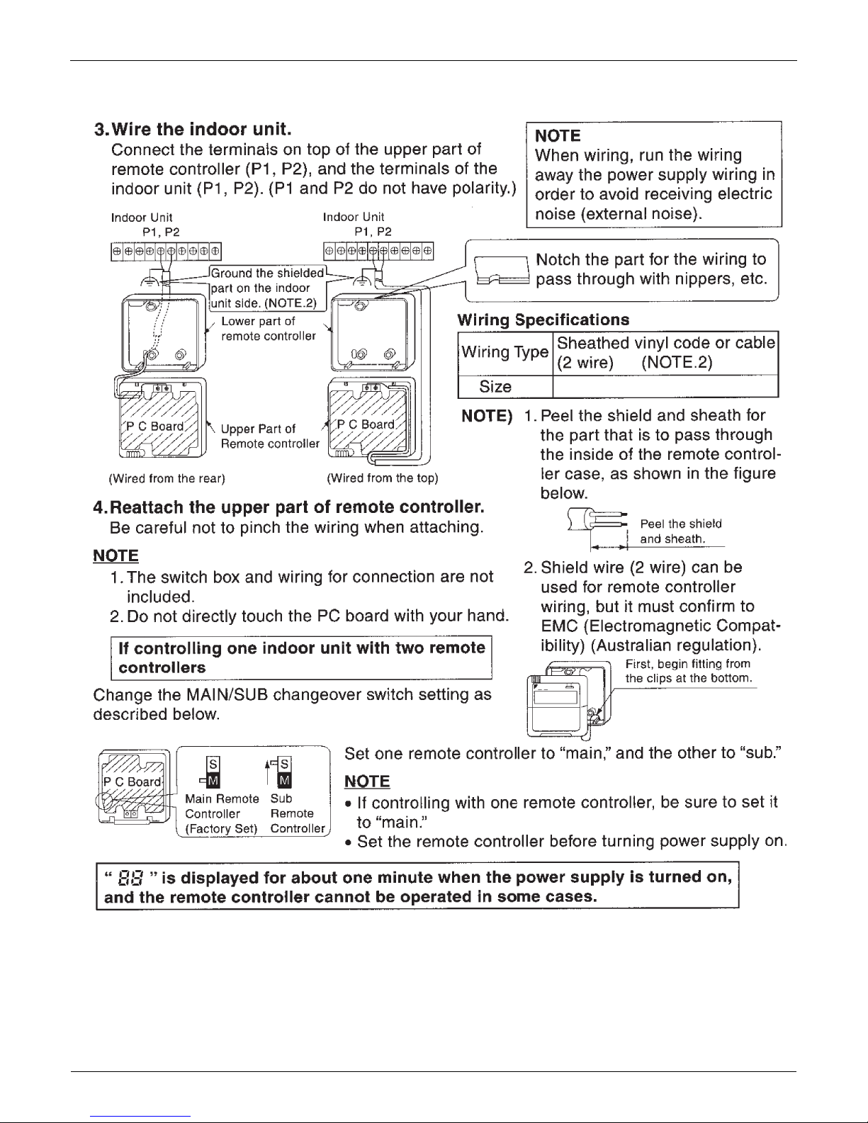
2.1 BRC1C71 Wired Remote Controller
The optional Remote Controller for indoor units provides versatile system control.
Remote controller wiring for a simplified BRC2A71 Remote Controller is the same as that of the standard BRC1C72
Remote Controller. Because the functions of the simplified remote controller are limited, we recommend using in
combination with a central remote controller.
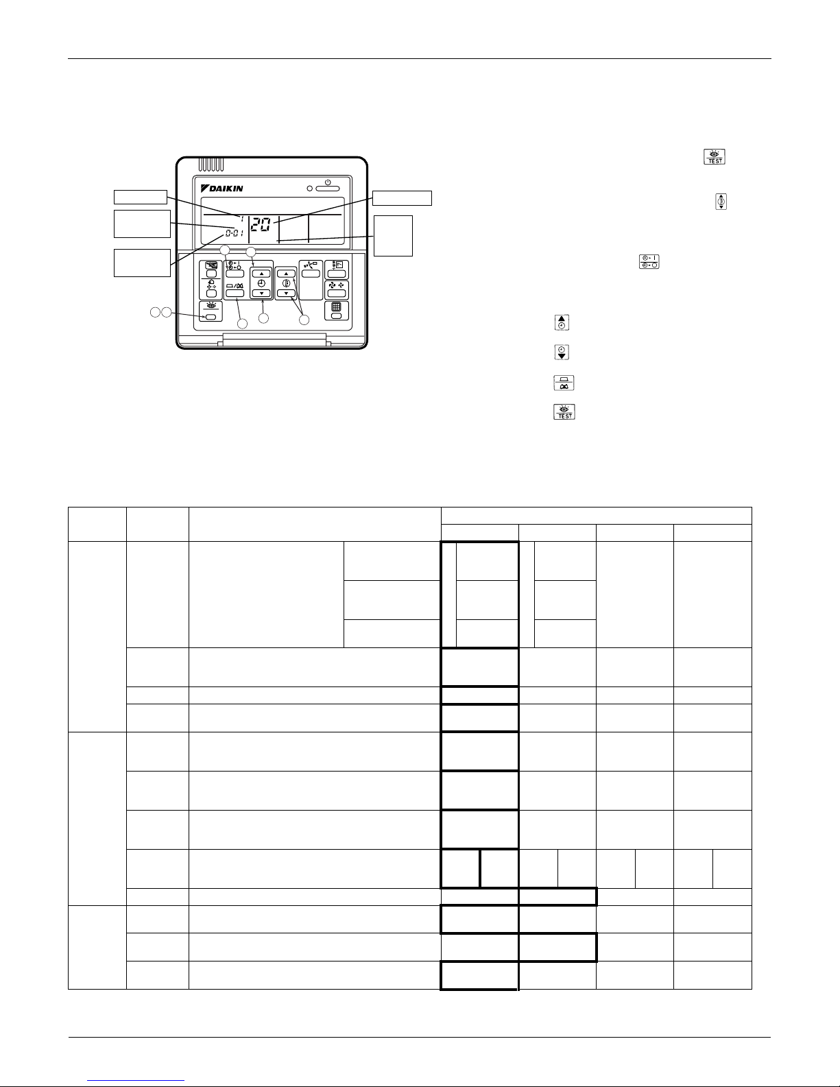
2.1.1 Appearance and Functions
2.1.2 Example of Control by Remote Controller
Large liquid crystal screen displays complete operating status.
Digital display allows temperature settings in 1°F units.
Operation start/stop can be programmed using timer for periods up to 72
hours.
Thermostat sensor provides room temperature control for optimum
comfort.
Microcomputer monitors room temperature and preset temperature,
automatically selecting cool/heat operation. (VRV System Heat Recovery
Series only)
Use any indoor remote controller to select cool, heat, or fan mode without
using the main cool/heat selection switch.
Continuous monitoring of 40 possible malfunctions with self-diagnosing
capability for messaging you immediately in the event of a problem.
Allows a variety of field settings from remote controller.
Control Devices EDUS39-605
4 Controls
2.1.3 Two Remote Controllers
1 indoor unit is controlled by 2 remote controllers from 2 separate locations
This is a convenient system for operating an office indoor unit from the reception area, or an indoor unit from a local or
remote location.
Operation mode of the indoor unit is last command priority.
Remove the front panel of the remote controller and set the main/sub changeover switch on the PC board to MAIN
for the main remote controller, and to sub SUB for the sub remote controller.
Note:
The remote controller is equipped with a thermostat sensor. If the main and sub remote controllers are mounted in
separate rooms, set the main remote controller so that its thermostat sensor is not used so that it does not determine
the temperature for all rooms.
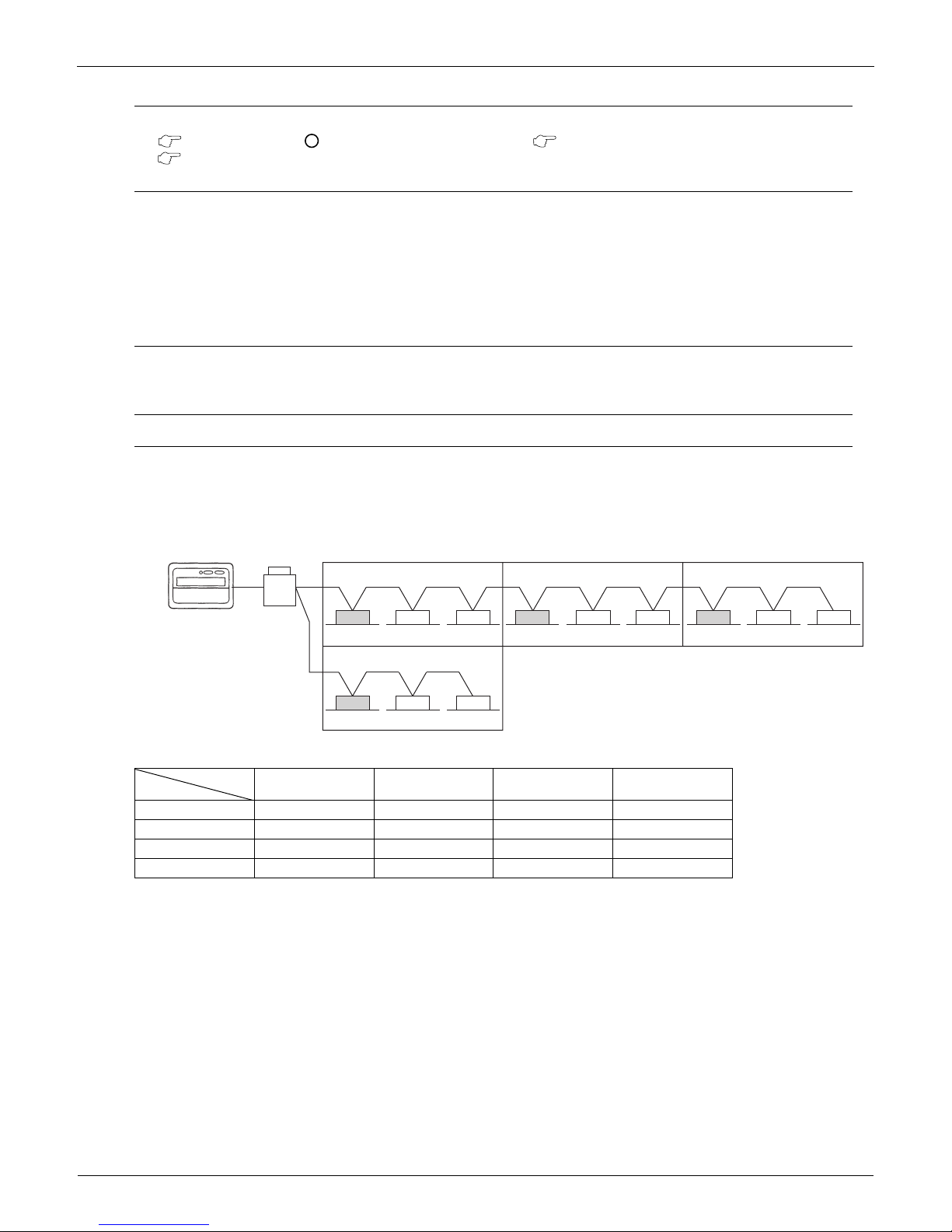
2.1.4 Group Control
Simultaneous control of up to 16 units with a single remote controller:
The following diagram illustrates a convenient system for simultaneous control of several indoor units on a wide, single
floor.
Wiring for remote controller group control has no polarity, therefore P
1
and P2 can be switched.
All indoor units within the group have the same setting, and each indoor unit is controlled individually by its own built-
in thermostat.
Because automatic address is used, an address does not have to be set by remote controller for group control.
Note:
Only remote controller wiring is shown.
EDUS39-605 Control Devices
Controls 5
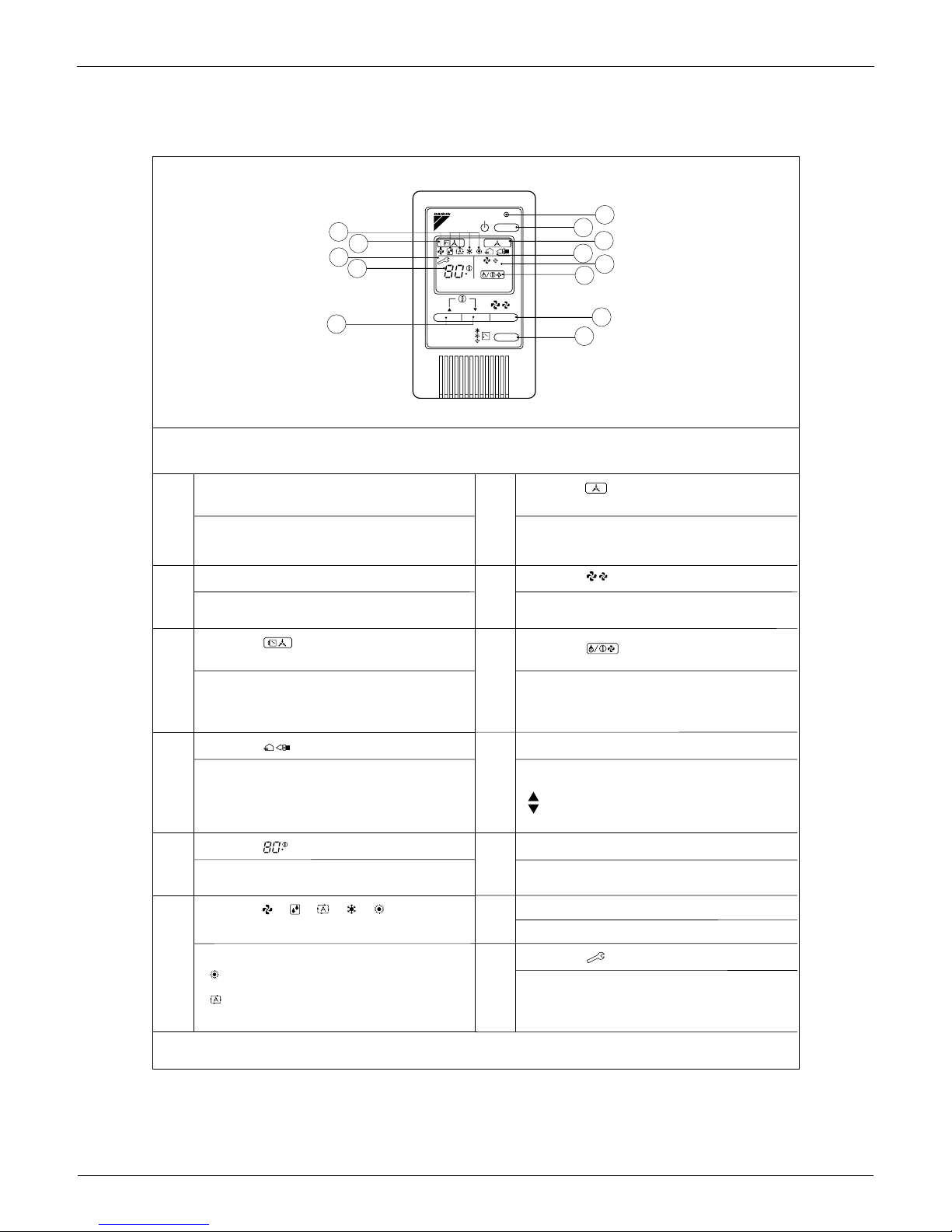
2.1.5 Remote Controller and Changeover Switch: Name and Function of Each Switch and
Display
1. ON/OFF button
Press tto start; press again to stop system.
2. Operation lamp red
The lamp lights during operation.
3. Display indicates changeover under control
It is impossible to changeover heat/cool with the remote controller when this icon is displayed.
4. Display indicates air flow flap
Refer to the chapter Operation procedure - Adjusting the air flow direction.
5. Display indicates ventilation/air cleaning
6. Shows that optional accessories total heat exchange and/or air cleaning unit are operating. Display set
temperature
Shows the temperature set.
7. Display
"" "" "" ""
operation mode
. Shows current operation mode.
8. Display programmed time
Shows the programmed time of the system start or stop.
9. Display indicates inspection/test operation
10.When the inspection/test operation button is pressed, the display indicates current mode. Display
indicates under centralized control
Indicates system is under centralized control. This is not a standard specification.
11.Display indicates fan speed
Indicates fan speed selected.
12.Display indicates it is time to clean air filter
Refer to the indoor unit manual.
13.Display indicates defrost/hot start
Refer to the chapter Operation procedure - Explanation of heating operation.
14.Timer mode start/stop button
Refer to the chapter Operation procedure - Programming start and stop of the system with timer.Timer on/off button
Refer to the chapter Operation procedure - Programming start and stop of the system with timer.
15.Inspection/test operation button
Only used by qualified service persons for maintenance purposes.
16.Programming time button
Program start and/or stop time.
17.Temperature setting button
Set the desired temperature.
18.Filter sign reset button
TEST

Control Devices EDUS39-605
6 Controls
Refer to the indoor unit manual.
19.Fan speed control button
Select the fan speed.
20.Operation mode selector button
Select the operation mode. o
21.Air flow direction adjust button
Refer to the chapter Operation procedure - Adjusting the air flow direction.
22.Fan only/air conditioning selector switch
Set the switch to for fan only operation or to for heating or cooling operation.
23.Cool/heat changeover switch
Set the switch to for cooling or to for heating operation.
NOTE:
Unlike actual operation, all indicators are simultaneously displayed in Figure 1 in order to illustrate the many available
options.
If the filter sign lamp lights up, clean the air filter as explained in the indoor unit manual. After cleaning and reinstalling
the air filter, press the filter-sign reset button on the remote controller and the sign deactivates.

EDUS39-605 Control Devices
Controls 7
2.1.6 Installation
Control Devices EDUS39-605
8 Controls
18 – 2AWG
EDUS39-605 Control Devices
Controls 9
2.1.7 Field Setting Wired Remote Controller BRC1C71
Field Setting Contents and Code No.
If optional accessories are mounted on the indoor unit, its settings may have to be changed. Refer to the instruction manual
for each setting.
Procedure
1. When in the normal mode, press the
button for a minimum of four seconds, and the
FIELD SET MODE is entered.
2. Select the desired MODE NO. with the
button O.
3. During group control, when setting by each
indoor unit (mode No. 20, 21 and 23 have
been selected), push the button (P) and
select the INDOOR UNIT NO to be set. This
operation is unnecessary when setting by
group.
4. Push the upper button Q and select
FIRST CODE NO.
5. Push the lower button R and select the
SECOND CODE NO.
6. Push the button S once and the present
settings are SET.
7. Push the button T for about one second
to return to the NORMAL MODE.
Example: If set for group setting and the time to clean air filter is set to: FILTER CONTAMINATION-HEAVY, you should set
MODE NO. to [10], FIRST CODE NO. to [0] and SECOND CODE NO. [02].
Mode No.
Note)1
FIRST
CODE No.
Description of Settings
SECOND CODE NO. Note)4
01 02 03 04
10(20)
0
Filter Contamination-Heavy/
Light: Setting for display time
to clean air filter. Time alert to
clean air filter is cut in half
when heavy filter
contamination.
UltraLong-Life
Type
Light
Approx.
10,000
hours
Heavy
Approx.
5,000
hours
——
Long-Life Type
Approx.
2,500
hours
Approx.
1,250
hours
Standard Type
Approx.
200 hours
Approx.
100 hours
1
Long-life or Standard filter type: Setting of filter
indication time. Change setting to Ultralong-life
filter if one is installed
Long-Life
Filter
Ultra-Long-
Life Filter
——
2 Thermostat Sensor in Remote Controller Use Not Use — —
3
Display Time to Clean Air Filter Calculation (Set
when filter sign is not to be displayed
Display
Do not
Display
——
12(22)
0
Optional accessories output selection field
selection of output for adaptor for wiring
Indoor Unit
Turned ON by
Thermostat
—
Operation
Output
Malfunction
Output
1
ON/OFF Input from Outside: Set when ON/OFF is
to be controlled from outside.
Forced Off
ON/OFF
Control
External
Protection
Device
—
2
Thermostat Differential Changeover: Set when
remote sensor is to be used.
FXFQ only
1°C 0.5°C — —
4
Automatic mode differential: Automatic
temperature differential setting for VRV system
heat recovery series cool/heat
01 : 0 02 : 1 03 : 2 04 : 3 05 : 4 06 : 5 07 : 6 08 : 7
5 Power failure automatic reset: Auto Restart Not equipped Equipped — —
13(23)
1
Selection of Air Flow Direction: Set when a blocking
pad kit has been installed FXFQ only
F
(4 directions)T(3 directions)W(2 directions)
—
4 Field set airflow position setting
Draft
Prevention
Standard
Ceiling Soiling
Prevention
—
5
Field set fan speed selection: Fan speed control by
air discharge outlet for phase control
Standard
Optional
Accessory 1
Optional
Accessory 2
—
TEST
SETTIING
Unit NO.
UNIT NO.
SECOND
CODE NO.
MODE NO.
FIELD
SET
MODE
FIRST
CODE NO.
2P068938
1 7
6
3
4
5
2
Control Devices EDUS39-605
10 Controls
Notes:
1. Setting is carried out in the group mode. If the mode number inside the parentheses is selected, indoor units can also
be set individually.
2. The SECOND CODE number is set in the bold bordered display when shipped from the factory.
3. Mode not displayed if the indoor unit is not equipped with that function.
4. When returning to the normal mode, [
88
] may be displayed in the LCD in order for the remote controller to initialize
itself.
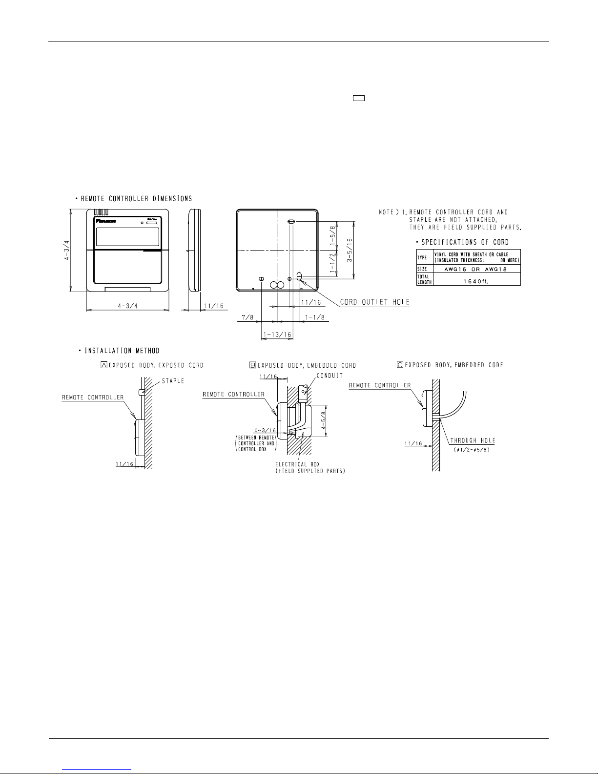
2.1.8 Dimensions
BRC1C71
3D045753
18-2 AWG
EDUS39-605 Control Devices
Controls 11
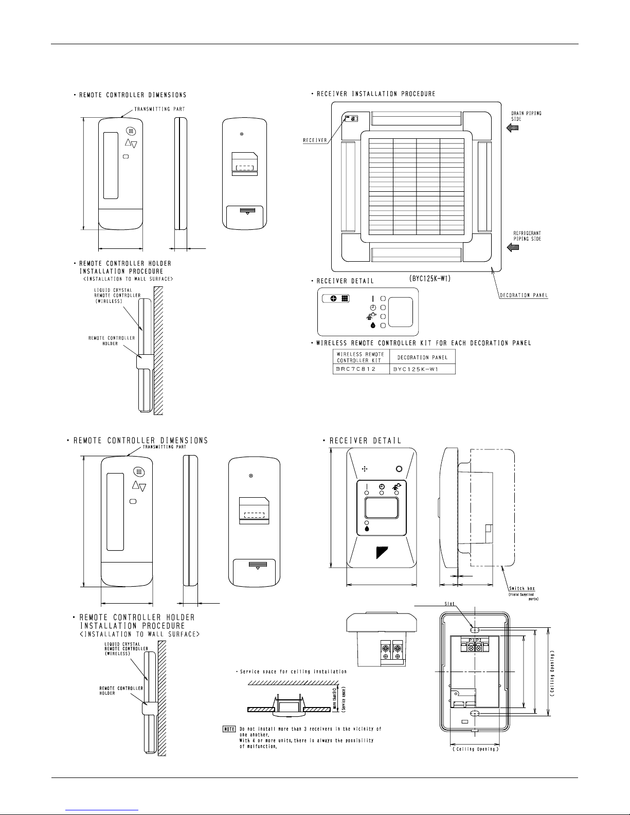
2.2 BRC4C / 7C / 7E Wireless Remote Controller / Receiver
BRC7C812
BRC4C82
C:3D005912D
2-7/16 11/16
6-3/16
C:3D007898A
2-7/16 11/16
2-3/4
2-3/16×3/8
11/16
1-3/8
1-15/16
1/32
6-3/16
4-3/4
2-13/16
3-5/16
4-3/16
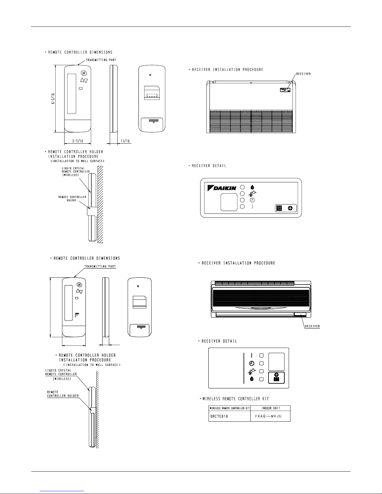
Control Devices EDUS39-605
12 Controls
BRC7E83
BRC7E818
3D049336
C:3D034905B
2-7/16
11/16
6-3/16
EDUS39-605 Control Devices
Controls 13
2.3 BRC2A71 Simplified Remote Controller
2.3.1 Name and Function
DISPLAY Ò Ó (CHANGEOVER UNDER
CONTROL)
DISPLAY Ò Ó (VENTILATION/AIR
3P146204
REMOTE CONTROLLER: NAME AND FUNCTION OF EACH SWITCH AND DISPLAY
ON/OFF BUTTON
Press the button and the system will start. Press the
button again and the system will stop.
OPERATION LAMP (RED)
The lamp lights up during operation. Blinks in case of stop
due to malfunction.
It is impossible to changeover heating/cooling with the
remote controller when it shows this display. (As for details,
see “SETTING OF MASTER REMOTE CONTROLLER” in
the installation manual attached to the indoor unit.)
DISPLAY “ ” (UNDER CENTRALIZED
CONTROL)
When this display shows, the system is UNDER
CENTRALIZED CONTROL.
(This is not a standard specification)
This display shows that the total heat exchanger and the
air cleaning unit are in operation. (These are optional
accessories).
DISPLAY “ ” (SET TEMPERATURE)
This display shows the set temperature. Only given during
a cooling or heating operation.
DISPLAY “ ” “ ” “ ” “ ” “ ”
(OPERATION MODE)
This display shows current OPERATION MODE.
“ ” is not available with outdoor units specially designed
for cooling only.
“ ” is reserved only for outdoor units capable of heat
recovery.
DISPLAY “ ” (DEFROST / HOT START)
Indicates that defrost or hot start (during which the fan is
stopped till the temperature of air supply rises enough at
the start of a heating operation) is in progress.
TEMPERATURE SETTING BUTTON
Use this button for SETTING TEMPERATURE of the
thermostat.
; Each press raises the set temperature by 1 F.
; Each press lowers the set temperature by 1 F.
The variable temperature range is between 60 F and 90 F.
FAN SPEED CONTROL BUTTON
Press this button to select the fan speed, HIGH or LOW,
of your choice.
OPERATION MODE SELECTOR BUTTON
Press this button to select OPERATION MODE.
DISPLAY “ ” (MALFUNCTION)
Indicates malfunction and blinks if the unit stops operating
due to malfunction.
(As for details, see “TROUBLE SHOOTING” in the
operation manual attached to the outdoor unit.)
DISPLAY “ ” (FAN SPEED)
This display shows the fan speed: HIGH or LOW.
For the sake of explanation, all indications are shown in the figure above contrary to actual running situations.
6
3
13
5
10
12
11
9
8
4
7
1
2
F
HL
F
BRC2A71
H L

Control Devices EDUS39-605
14 Controls
2.3.2 Installation
3P146205-1
1. Remove the upper part of remote controller.
Insert a minus screwdriver into the
slot between the upper and the
lower part of remote controller.
NOTE
1. Do not directly touch the PC
board with your hand.
2. Wire the indoor unit.
Connect terminals P1 and P2 on the rear of
the lower part of remote controller to
terminals P1 and P2 on the indoor unit.
(Terminals P1 and P2 have no polarity.)
3. Fasten the remote controller.
Attach the lower part of remote controller to the electric parts box
(part to be procured in the field).
NOTE
Choose the flattest place possible for the mounting surface. Be
careful not to distort the shape of the lower part of remote controller
by over-tightening the mounting screws.
For the electric parts box to be procured in the field, use optional
accessories KJB111A.
NOTES
1. The electric par ts box and wiring for connection are not included.
2. When wiring, run the wiring away the power supply wiring in order to
avoid receiving electric noise (external noise).
3. When wiring, refer to the wiring diagram of indoor unit (attached to
indoor unit) as well.
WIRING SPECIFICATION
Wiring type
Size
Sheathed wire (2 wire)
AWG18 or AWG16
4. Initial setting
Change the MAIN/SUB changeover switch
setting as described below.
If controlling one indoor unit with two remote
controllers, set one remote controller to
"
MAIN." and the other to "SUB.
"
Main Remote
Controller
(Factory Set)
Sub Remote
Controller

EDUS39-605 Control Devices
Controls 15
2.3.3 Dimensions
5. Reattach the upper part of remote controller.
NOTE
1. Do not directly touch the PC board with your hand.
NOTES
2If controlling with one remote controller, be sure to set it to
"MAIN."
2Set the remote controller before turning power supply on.
" " is displayed for about one minute when the power supply is
turned on, and the remote controller cannot be operated in some cases.
3P146205-2
3D047341
Control Devices EDUS39-605
16 Controls
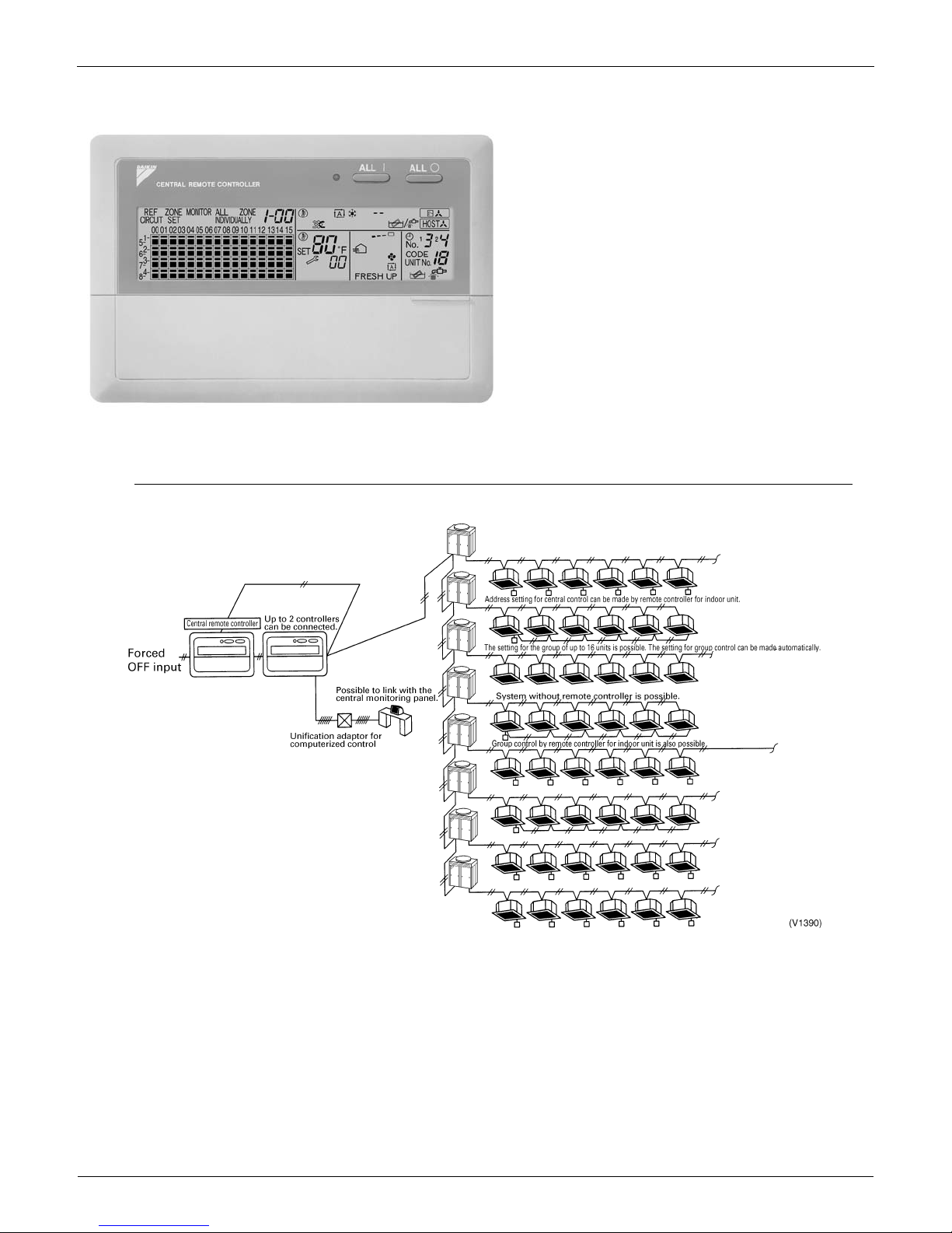
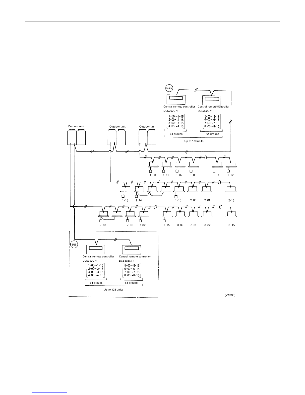
2.4 DCS302C71 Central Remote Controller
2.4.1 System Configuration
System Outline
You can connect up to 64 groups of indoor units
(maximum 128 units) and operate or monitor ON/OFF,
temperature settings, and so forth, by individual zone or
together.
Up to 2 units are connectable within 1 system and up to
4 units in case of the double central control mode.
Executes zone control for up to 64 zones and is
designed for operation efficiency.
Error contents are displayed in code so that
maintenance and inspections can be conducted
immediately.
1 schedule timer and up to 4 unified on/off controllers
can be connected to a single unit, and you can easily
extend the central control system according to building
size and purpose.
Applicable wiring methods include bus and star in
addition to series wiring.
EDUS39-605 Control Devices
Controls 17
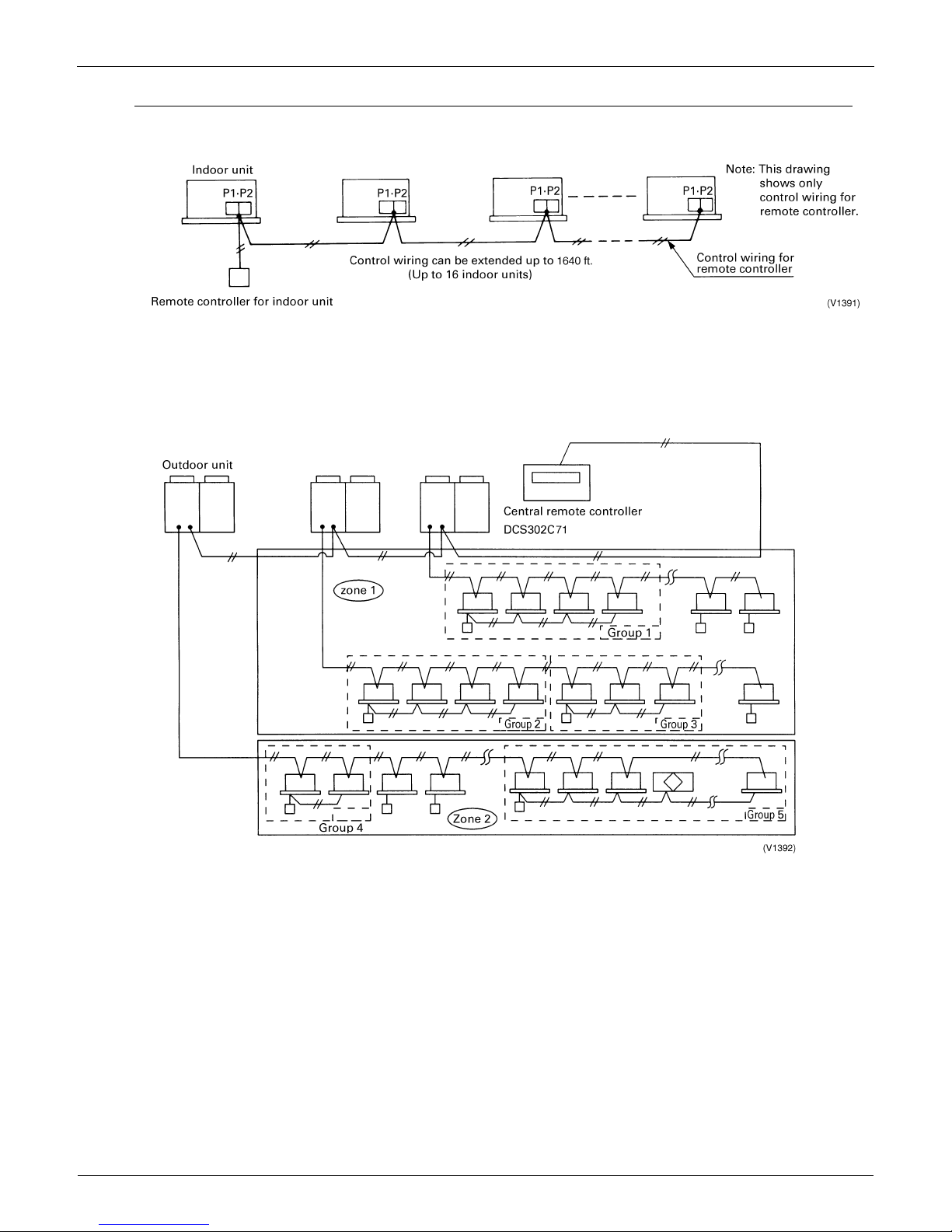
System Configuration for Group / Zone Control
Group control
Group control configuration allows all indoor units to be connected by the same remote controller connected to
terminal P1 and P2, and all the units in group have the same setting and the same operation.
The group of indoor units is controlled by the master indoor unit’s remote controller.
The maximum number of indoor units in one group is 16 units.
Zone control
A zone is a group of indoor units interconnected to terminal F1 and F2 utilizing one central remote controller that
applies the same settings to all units.
The zone control of the indoor unit is operated by the central remote controller.
1 to 64 zones can be controlled by the central remote controller.
You can set up to 64 groups in one zone.
Up to 16 units can be set in one group, and up to 64 groups (up to 128 units) can be connected.
Control Devices EDUS39-605
18 Controls
System Configuration (Control by 2 central remote controllers)
Up to 128 indoor units can be connected in one system.
2 or 4 central remote controllers are required. It is possible to control the same unit from 2 locations.
Up to 16 unified ON/OFF controllers can be connected using 8 controllers covering 2 locations.
One scheduling timer can be connected.
Notes:
1. Electrical power should be supplied to each central remote controller. (Single phase 100~240V)
2. When you control by 2 central remote controllers, be sure to set SS3 by the initial setting.
(
) When you control by 2 central remote controllers, the last entered setting takes priority.
Note:
The Operation Code Settingcannot be made by the sub side. Be sure to set by the main side.
EDUS39-605 Control Devices
Controls 19
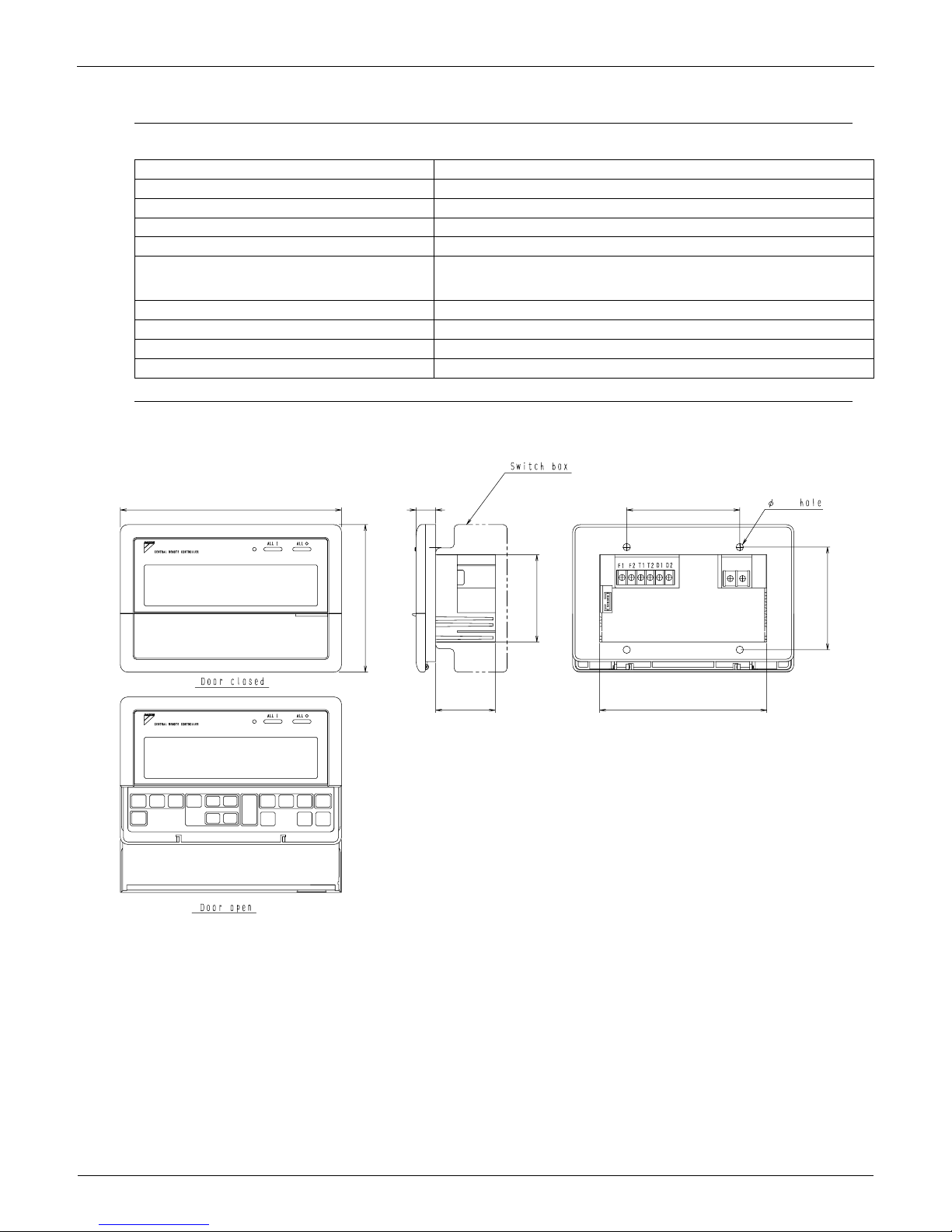
2.4.2 Specifications / Dimensions
Specifications
Dimensions
DCS302C71
DCS302C71
Power supply voltage / frequency AC100~240V ±10% 50/60Hz
Power consumption Max. 8W
Setting data backup Non-volatile memory preserves data semi-permanently
Effects of instantaneous power failure No effect for 20 mili-sec. or less
Forced OFF input
Operation on the local side cannot be carried out
during forced OFF input.
No-voltage normal open contact
Micro-current contact capable of handling 16VDC and approx. 10mA.
Max. 492 ft cable length
Power supply for schedule timer Power can be supplied to schedule timer. (Max. 1 unit)
Operating ambient temperature / humidity condition -5~40°C, 95% RH or less (no condensation)
Size (width × height × depth) 7 1/8×4 3/4×2 9/16 exposed portion of front panel: 5/8 (Unit: Inch)
Machine Weight (Mass) Approx. 0.95 lbs
Unit (in.)
7 1/8
5/8 3 5/8
3/16
5 3/8
3 5/16
1 15/16
4 3/4
2 13/16
C:3D043353
Control Devices EDUS39-605
20 Controls
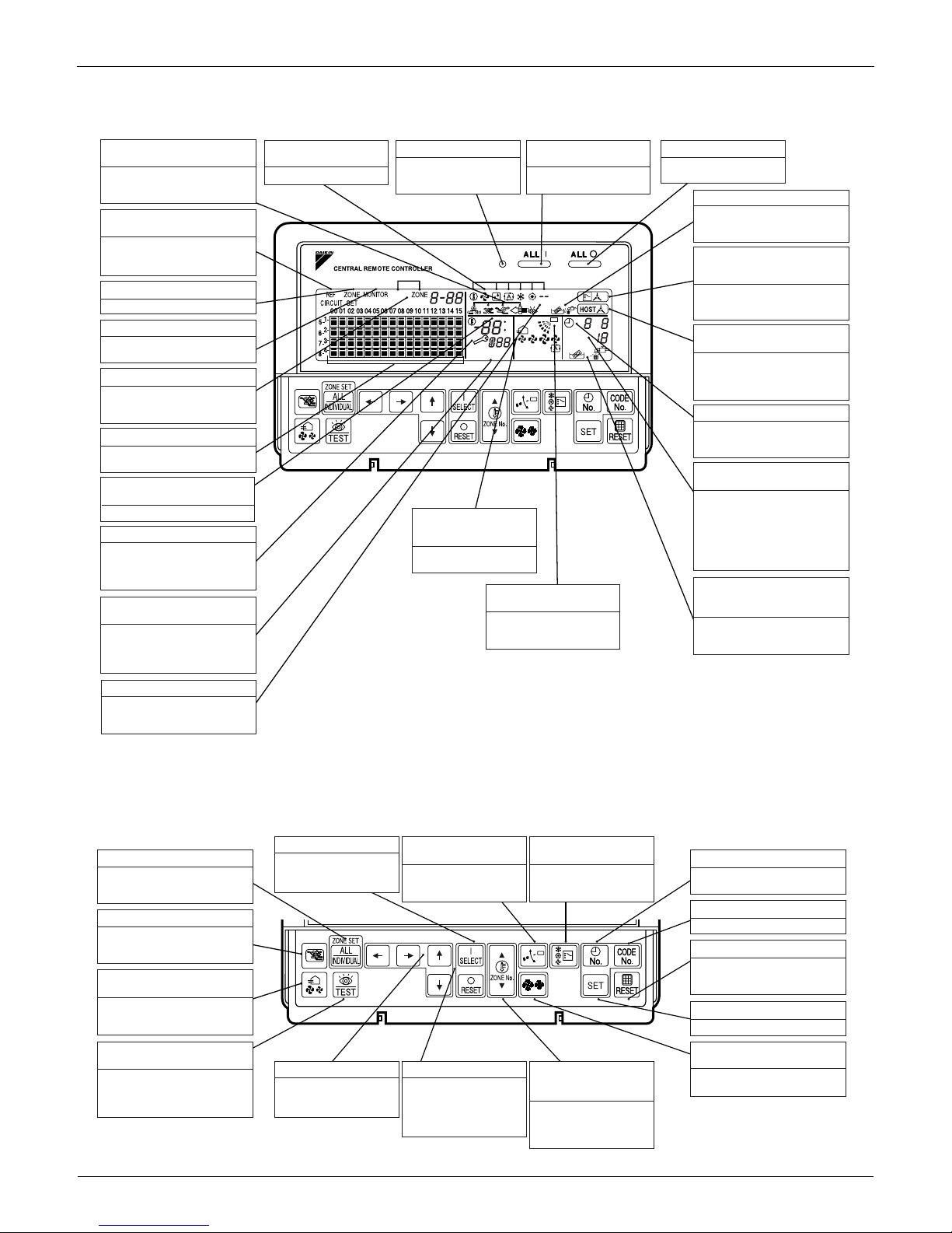
2.4.3 Names and Functions of Operating Part
Display part DISPLAY (OPERATION MODE) Displays operating state.
Control Section
ALL
OPTION
L
NOT
T
AV
AILABLE
SET
FRESH UP
H
HH
No.
.
CODE
UNIT No.
TEST
INDIVIDUALLY
C
F
12
DISPLAY(VENTILATION
CLEANING DISPLAY)
This is displayed when a Ventiair
total enthalpy heat exchanger unit
or other such unit is connected.
DISPLAY (ZONE SETTING)
The lamp is lit while setting zones.
DISPLAY
The status displays indicates either
batch functions or which zone or
individual unit (or group) are being used.
DISPLAY (OPERATION MONITOR)
The lamp is lit while operation is
being monitored.
OPERATION MONITOR
Each square displays the state
corresponding to each group.
DISPLAY (MALFUNCTION CODE)
This displays (flashes) the content
of errors when an error failure has
occurred.In maintenance mode, it
displays the latest error content.
"NOT AVAILABLE" DISPLAY(NO
FUNCTION DISPLAY)
If a function is not available in the
indoor unit even if the button is
pressed, "NOT AVAILABLE" is may
be displayed for a few seconds.
DISPLAY (TIME TO CLEAN)
It lights up when any individual unit
(group) has reached the time for the
filter or element to be cleaned.
OPERATION LAMP (RED)
Lit white any of the indoor
units under control is in
operation.
UNIFIED OPERATION
BUTTON
Press to operate all indoor
units.
UNIFIED STOP BUTTON
Press to stop all indoor
units.
DISPLAY (COOLING/HEATING
SELECTION PRIVILEGE NOT
SHOWN)
For zones or individual units (groups)
for which this is displayed, cooling and
heating cannot be selected.
DISPLAY (UNDER HOST COMPUTER
INTEGRATED CONTROL)
While this display is lit up, no settings
can be made. It lights up when the upper
central machines are present on the
same air conditioning network.
DISPLAY (TIME NO.)
Displays the operation timer No.
when used in conjunction with the
schedule timer.
DISPLAY (OPERATION CODE
AND UNIT NUMBER DISPLAY)
The method of operation (remote
controller prohibited, central operation
priority after-press operation priority,
etc.) is displayed by the
corresponding code.This displays the
numbers of any indoor units which
have stopped due to an error.
DISPLAY (TIME TO CLEAN AIR
CLEANER ELEMENT/TIME TO
CLEAN AIR FILTER)
Displayed to notify the user it is time
to clean the air filter or air cleaner
element of the group displayed.
DISPLAY (REFRIGERANT
SYSTEM DISPLAY)
This indication in the square is lit
while the refrigerant system is
being displayed.
DISPLAY (OPERATION
MODE)
Displays operating state.
DISPLAY (PRESET
TEMPERATURE)
Displays the preset temperature.
DISPLAY (VENTILATION
STRENGTH/SET FAN
STRENGTH DISPLAY)
This displays the set fan
strength.
DISPLAY (FAN DIRECTION
SWING DISPLAY)
This displays whether the fan
direction is fixed or set to
swing.
DISPLAY (INSPECTION/TEST)
Pressing the maintenance/test run
button(for service) displays this. This
button should not normally be used.
ALL/INDIVIDUAL BUTTON
Pressing this button scrolls through
the "all screen", "zone screen", and
"individual screen".
VENTILATION MODE BUTTON
This is pressed to switch the
ventilation mode of the total
enthalpy heat exchanger.
VENTILATION STRENGTH
ADJUSTMENT BUTTON
This button is pressed to switch the
ventilation strength ("fresh up") of
the total enthalpy heat exchanger.
INSPECTION/TEST RUN BUTTON
(FOR SERVICE)
Pressing this button scrolls through
"inspection", "test run", and
"system display". This button is not
normally used.
TIME NO. BUTTON
Selects time No. (Use in conjunction
with the schedule timer only).
CONTROL MODE BUTTON
Selects control mode.
FILTER SIGN RESET BUTTON
This button is pressed to erase the
"clean filter" display after cleaning or
replacement.
SET BUTTON
Sets control mode and time No.
FAN STRENGTH ADJUSTMENT
BUTTON
Pressing this button scrolls through
"weak", "strong", and "fast".
ON/OFF BUTTON
Starts and stops ALL,
ZONE, and INDIVIDUAL
units.
FAN DIRECTION
ADJUSTMENT BUTTON
This button is pressed when
setting the fan direction to
"fixed" or "swing".
OPERATION MODE
SELECTOR BUTTON
This sets the operation
mode. The dry setting
cannot be done.
ARROW KEY BUTTON
This button is pressed
when calling an individual
indoor unit or a zone.
ZONE SETTING BUTTON
Zone registration mode can
be turned on and off by
pressing the start and stop
buttons simultaneously for at
least four seconds.
TEMPERATURE
ADJUSTMENT BUTTON
(ZONE NUMBER BUTTON)
This button is pressed when
setting the temperature. Select
the zone number if any zones
have been registered.
EDUS39-605 Control Devices
Controls 21
2.4.4 Description of Functions
Individual Screen, All Screen, Zone Screen
This controller can perform operations in the following screens:
INDIVIDUAL SCREEN for performing group operations.
ALL SCREEN for performing operations for all units at once.
ZONE SCREEN for performing zone operations.
Basic functions
Zone control functions
Function Descriptions of outline
Individual/Zone control Up to 64 groups (Max. 128 units and max. 16 units per group) of indoor units and HRV units
can be controlled by individually or by zone.
Unified ON/OFF ON/OFF can be set for each zone, and can be controlled simultaneously for entire system
by push button or by remote controller.
Malfunction code display The status of each group is always displayed, such as ON/OFF, error, etc. If the error
occurs, it displays the malfunction code and type of error with the self-diagnosis function.
Connection of unification adaptor for
computerized control
By connecting the optional unification adaptor for computerized control , it can be linked with
the central monitoring panel by contact signal, which enables you to operate ON/OFF
simultaneously, and monitor the operating status.
Remote control acceptance/rejection It is possible to restrict the function of local remote controller:Only ON operation rejection,
or ON/OFF operation rejection.
2 central controllers By connecting two central remote controllers, the same air-conditioner can be controlled
from 2 locations: By tenant or administration office.
Function Descriptions of outline
Zone control The zone function is a function to control one or more groups of airconditioners, and
operation settings, such as ON/OFF, can be made by zone.
Up to 64 zones Up to 64 zones (64 groups for each zone) can be set. However, the group setting spreading
over the plural zone cannot be set.
Zone register When the power is supplied the first time, each group is registered in its respective zone.
You can register several groups in the same zone by switch, to enable simultaneous
operation of the units immediately. The temperature setting is also controlled by zone
simultaneously.
Zone setting By adding the zone setting function (Zone “0”) from the central remote controller, you can
make one setting for all the zones registered by single operation.
ON/OFF control of zone For example, if there are three groups in one room and if you register these three groups as
one zone, you can operate all three simultaneously by single operation (ON/OFF,
temperature setting, and so forth.
You can also operate each group individually by local remote controller.
Maintaining zone setting Even if the power is turned off, the zone configurations set are maintained semi-permanently
and saved in non-volatile memory.
Cool/Heat changeover by zone The cool/heat changeover can be made by zone if you establish a master group for Cool/
Heat changeover for that zone.
Batch operation The same setup is possible at one operation to all the groups registered on the "All" screen.
No local remote controller Even without a local remote controller, you can still perform the same batch operation.
However, in this case, each air-conditioning unit consists counts as group.
Combination with other controllers You can combine opeations with a unified ON/OFF controller and a schedule timer.
Refer to the system configuration for details.
Connection to central monitoring panel You can combine with an Interface for use in BAC net
and a data station in order to connect
to the central monitoring panel. A parallel interface can also be connected.
Control Devices EDUS39-605
22 Controls
Cool/Heat changeover and settings
NOTE:
Cool/heat Mode-setting capability for the Indoor Unit Remote Controller:
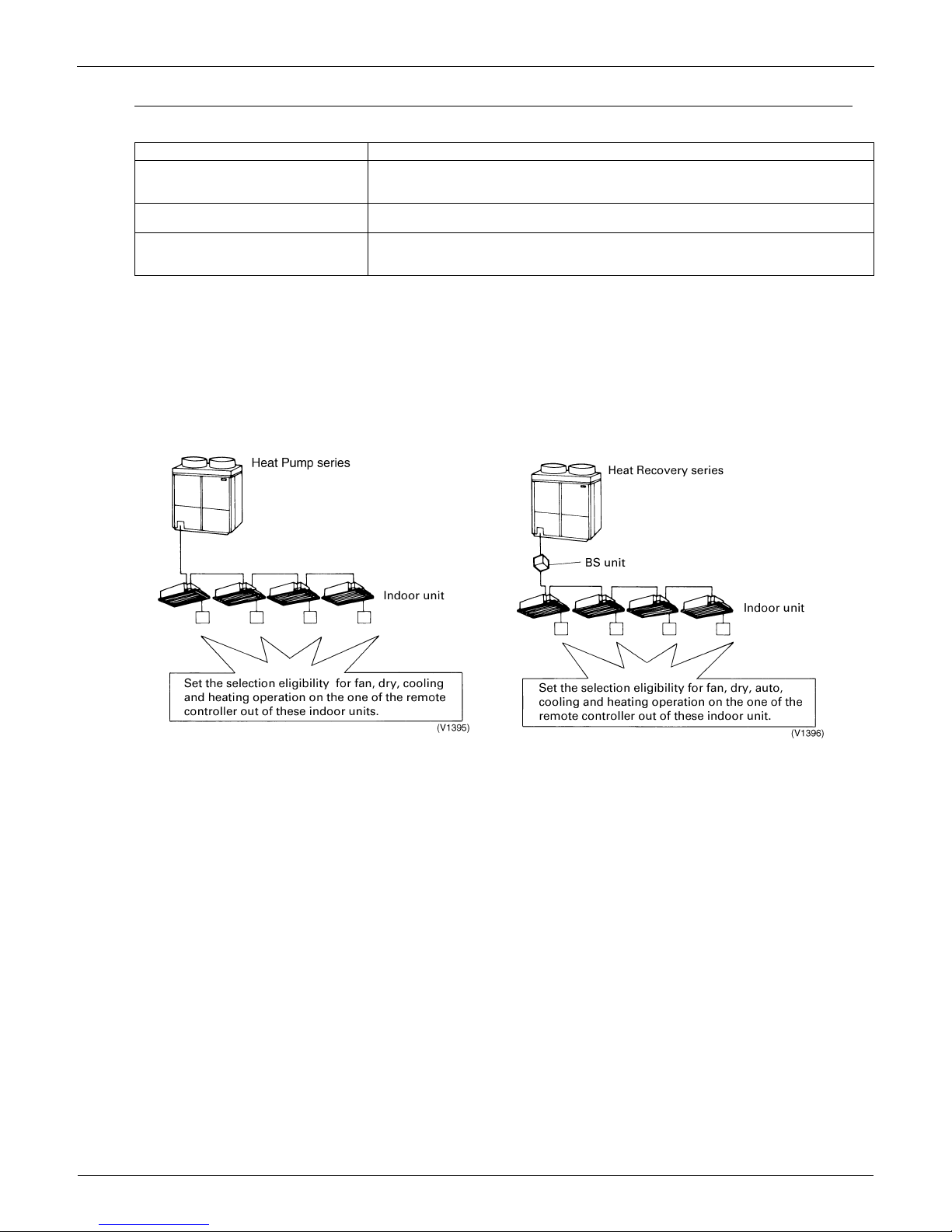
The outdoor unit’s operation mode of fan, dry, auto (available only with Heat Recovery units), cooling, or heating can be
selected usingthe indoor unit’s designated primary remote controller that is connected to the outdoor unit. The settings
chosen for the primary remote controller determine the settings for the remaining controllers. . For the Heat Recovery
series, if 2 or more indoor units are connected to one BS unit, you must set the fan, dry, auto, cooling, or heating
operation on the primary remote controller connected to the BS unit.
Only remote controller designated for settings can change the operation mode.
Setting method for cool/heat
1. Preparation
When turning on the power the first time, the CHANGEOVER UNDER CONTROL sign blinks.
Function Descriptions of outline
Possible control The operation mode of the outdoor unit can be changed by the local remote controller or by
the central remote controller. For test operation, change setting of cool/heat selector switch
of the outdoor unit.
Remote controller acceptance/rejection You can set acceptance/rejection on the central remote controller with the local remote
controller.
NOT AVAILABLE display
Pressing a button for an unavailable function in the indoor unite activates the NOT
AVAILABLE display.
EDUS39-605 Control Devices
Controls 23
Use the following procedure to set operation mode:
Description of operation and its function:
Note: Selection modes are also available on the wireless remote controller. It is not possible to set DRY mode with the
Central Remote Controller.
Continue to push Operation switch
for about 4 seconds.
sign blinks on all the indoor units
connected to the outdoor unit or BS
unit.
Push Operation switch of the remote
controller, which you want to set the
selection eligibility. This completes the
setting procedure. Cool/heat selection
eligibility is set for that remote controller,
and sign goes off.
still blinks on all other remote
controllers.
Push Operation switch of remote
controller having the selection
eligibility (The remote controller not
displaying sign) several times
to select the desired operation mode.
[Fan], [Dry], [Auto](only for Heat Recovery
series),[Cooling] and[Heating] mode are
selected each time you push the
[Operation switch]. Operation mode of
other remote controllers, which has no
selection eligibility, is also switched
automatically.
1
2
3
2. Selection Eligibility
Setting
3. Operation mode
changeover
(V1397)
Operation ON/OFF
(V1398)
Remote control having the
selection eligibility
Remote controller having
no sign.
( )
Other remote controller
Remote controller having
no sign.
( )
Remote control having the
selection eligibility
Remote controller having
no sign.
( )
Other remote controller
Remote controller having
no sign.
( )
Set to Cooling, Heating
and Auto (only for Heat
Recovery series);
Set to [Fan];
• Changes to the operation mode
selected by the remote controller
having the selection eligibility.
• However, you can still change to
[Fan], or change from [cooling] to
[dry].
• Can only be set to [Fan].
Control Devices EDUS39-605
24 Controls
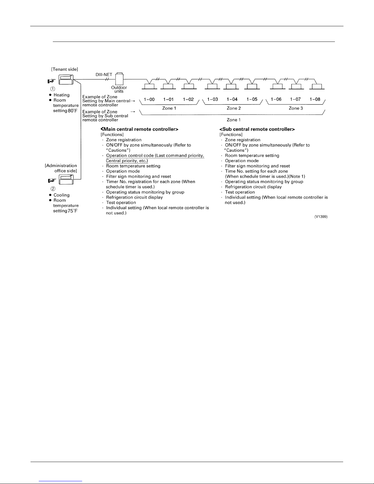
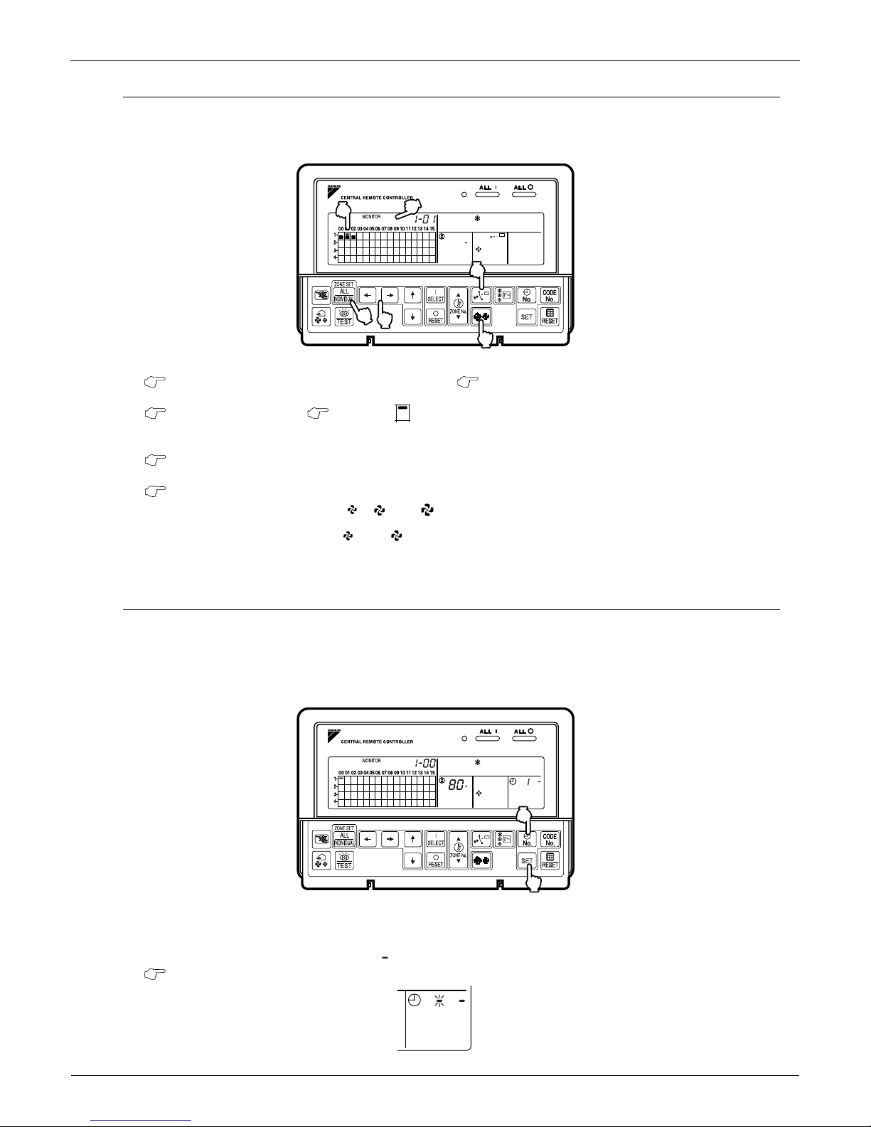
Control with Two Central Remote Controllers
The central remote control equipment is the newly designed C type that allows 2 central remote controllers to be
connected as shown in the following example:
Note:
If a timer number is registered by the sub central remote controller, the timer mode for the local remote controller
(mode no. 8, 9, 18, and 19) for the same units set by the Main remote controller are deactivated.
Explanation of the above figure
If you operate the central remote controller in the sequence of N and O, the indoor unit is set for cooling / temperature
setting 75°F.
However, the display of zone setting of the master remote controller remains at heating / temperature setting at 80°F.
Cautions
Operation code cannot be set by the sub central remote controller.
Combined zone operation can only be set by zone registration of the main central remote controller.
Both main and sub central remote controller are operated by the most recent command for the functions other than
the above.
The display on the central remote controller cannot be changed by other controllers. On the display for the group, you
can monitor the present operation status.
EDUS39-605 Control Devices
Controls 25
Sequential Start
Operation command from central control equipment
Each unit operates in sequence. For example, if you set simultaneous operation by the central remote controller for
groups 1-00 ~ 4-15, and 5-00 ~ 8-15, two outdoor units start simultaneously.
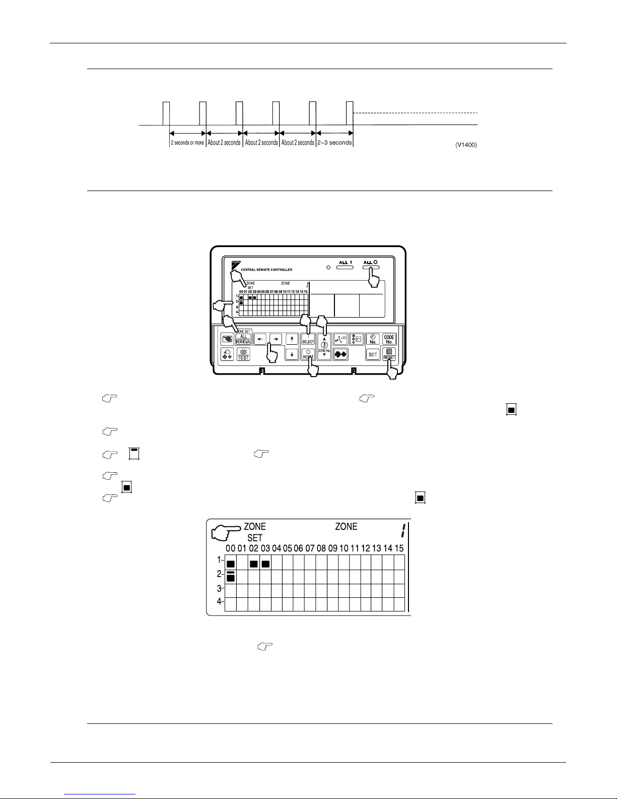
Registering Zone
It is possible to set multiple groups as one zone and control each zone separately.
No zones are registered when the unit is shipped from the factory.
Zone registration can be done in the individual screen, all screens, or the zone screen.
Registration
1. Pressing the ALL/INDIVIDUAL button for four seconds. Displays ZONE SET.
Zone Number 1 is displayed, and if there are any groups already registered in the displayed zone, a will light up
on the operation monitor.
2. Select the Zone Number to be registered using the ZONE NUMBER button.
Keeping the button pressed down moves it rapidly.
3. " to the group you wish to register using the arrow keys.
Keeping the button pressed down moves it rapidly.
4. Press the SELECT button to register that group to the zone.
The display lights up on all the selected units.
Pressing the RESET button removes the group from that zone, and goes off.
Repeat steps 3 and 4 until all the units you wish to register to the zone have been added.
In this example, a screen is shown with units 1-00, 1-02, 1-03, and 2-00 registered to Zone Number 1.
5. Repeat steps 2 to 4 to register to the next zone.
6. Once zone registration is complete, press the ALL/INDIVIDUAL button to turn off ZONE SET display
and return to the individual screen.
The display returns to the normal screen if nothing is done for one minute when in zone registration mode.
NOTE:
It is impossible to register one group to several different zones.
If this is done, the last zone registered is effective.
7
8
9
4
3
6
1
5
2
1
2
3
5
4
6
7
2
1
Control Devices EDUS39-605
26 Controls
Batch deletion of zone registration
1. Pressing the ALL for at least four seconds while pressing the FILTER SIGN RESET button when
ZONE SET is displayed deletes all zone registrations.
Zone setting
To set all zones for uniform operation, the central remote controller should display Zone 0 with the following modes
selected:
Operation mode
Control mode
Room temperature setting
Time Clock No.
NOT AVAILABLE Display
If a particular function is not available for the unit, NOT AVAILABLE displays for approximately two seconds when you
attempt to access that function.
If another unavailable function button is pushed, the NOT AVAILABLE display will continue an additional two seconds.
Monitor in a zone unit
Operating and monitoring the system in a group or by individual zones is enabled from the DCS302C71.
Monitoring in a zone is accessed by using an indoor unit with a lower address within the zone as the Main Indoor Unit.
The following options are displayed for monitoring zones:
If the system is operated on the Zone screen, the same setting is reflected for all indoor units registered with that zone.
On the Zone screen, ventilation mode can be only monitored, not changed. In order to change to ventilation mode, be
sure to use the Individual screen.
On the Batch screen, operating and monitoring is enabled to allow monitoring an indoor unit with a lower address within
the scope of control.
Main Indoor Unit
Operation Code
Timer No.
Temp. Display Operation Mode
Zone 1 1-00 1-00 1-00 1-00
Zone 2 1-03 1-03 1-03 1-03
Zone 3 1-06 1-06 1-07 1-07
Zone 4 2-00 2-00 N/A N/A
9
8
2
1-00 1-01 1-02
Zone 1
1-03 1-04 1-05
Zone 2
1-06 1-07 1-08
Zone 3
2-00 3-00 4-00
Zone 4
Central Remote
Controller
Outdoor Unit
Indoor Unit
EDUS39-605 Control Devices
Controls 27
Changing the Fan Direction and Fan Strength
Changing the fan direction and strength is accessed from the following screen: .
Registration
1. Press the ALL/INDIVIDUAL button to enter the individual screen.
The unit opens the individual screen automatically if nothing is done for one minute.
2. Using the arrow keys, move the to select the units to fan direction adjustment or fan strength
adjustment.
Keeping the button pressed down advances options rapidly.
3. Press the FAN DIRECTION ADJUSTMENT button.
This sets FIXED or SWING fan direction.
Press the FAN STRENGTH ADJUSTMENT button.
Pressing this button scrolls through , and .
Depending on the indoor unit, only and may be available.
The functions included in the indoor units may vary. Pressing a button for an unavailable function prompts NOT
AVAILABLE to display.
Timer Number Setting
Only when used with the schedule timer
Using this together with the schedule timer makes it possible to set on/off function four times a day.
Two settings of ON/OFF are possible to one Schedule Timer and two Schedule Timers can be registered into a Central
Remote Controller.
Registration
1. Pressing the TIMER No. button causes the number set for timer number 1 to blink.
If no timer setting has been made a dash [ ] is displayed. Select the desired timer number by pressing the
TIMER No.” button.
L
INDIVIDUALLY
F
1
2
3
6
5
4
80
1
2
3
4
5
6
L
H
H
HH
HH
L
H
H
L
No
No
.
INDIVIDUALLY
F
12
2
1
1
No
No
.
12
 Loading...