

Daikin DCM601A72 Installation Manual
Model
DCM601A72
Installation Manual
iTM plus adaptor

Disclosure
To the User in USA
Part 15 of FCC
Note: This equipment has been tested and found to comply with the limits for a Class B
digital device, pursuant to part 15 of the FCC Rules. These limits are designed to provide
reasonable protection against harmful interference in a residential installation. This equipment generates, uses and can radiate radio frequency energy and, if not installed and used
in accordance with the instructions, may cause harmful interference to radio communications. However, there is no guarantee that interference will not occur in a particular installation. If this equipment does cause harmful interference to radio or television reception,
which can be determined by turning the equipment off and on, the user is encouraged to
try to correct the interference by one or more of the following measures:
- Reorient or relocate the receiving antenna.
- Increase the separation between the equipment and receiver.
- Connect the equipment into an outlet on a circuit different from that to which the receiver
is connected.
- Consult the dealer or an experienced radio/TV technician for help.
FCC CAUTION
Changes or modications not expressly approved by the party responsible for compliance
could void the user’s authority to operate the equipment.
To the User in CANADA
Canadian ICES-003
This Class B digital apparatus complies with Canadian ICES-003.
Cet appareil numérique de la classe B est conforme à la norme NMB-003 du Canada.

Installation Manual 3P291714-4
DCM601A72 iTM plus adaptor
English
Safety Considerations
“All phases of the eld-installation, including, but not limited to, electrical, piping, safety,
etc. must be in accordance with manufacturer’s instructions and must comply with national,
state, provincial and local codes”
Read these SAFETY CONSIDERATIONS carefully before installing the controller.
After completing the installation, ensure that the unit operates properly during the startup
operation.
Train the customer to operate and maintain the unit. Inform customers that they should
store this Installation Manual with the Operation Manual for future reference.
Always use a licensed installer or contractor to install this product. Improper installation
can result in water or refrigerant leakage, electrical shock, re, or explosion.
Meanings of WARNING, CAUTION, and NOTE Symbols.
WARNING
CAUTION
NOTE
• Only qualied personnel must carry out the installation work.
• Consult your Daikin dealer regarding relocation and reinstallation of the con-
troller.
Improper installation work may result in leakage, electric shocks or re.
• Install the controller in accordance with the instructions in the installation man-
ual.
Improper installation may cause electrical shocks or re.
• Use only specied accessories and parts for installation work.
Failure to use specied parts may result in water leakage, electric shocks, re, or the
unit falling.
• Do not disassemble, reconstruct, or repair.
Electric shock or re may occur.
• Make sure that all wiring is secured, that specied wires are used, and that no
external forces act on the terminal connections or wires.
Improper connections or installation may result in re.
• Before touching electrical parts, turn off the unit.
Indicates a potentially hazardous situation which, if not
avoided, could result in death or serious injury.
Indicates a potentially hazardous situation which, if not
avoided, may result in minor or moderate injury.
It may also be used to alert against unsafe practices.
Indicates situations that may result in equipment or property-damage accidents only.
WARNING
3

Installation Manual 3P291714-4
DCM601A72 iTM plus adaptor
English
CAUTION
• Keep water out of the controller.
• To avoid leakage and electric shock due to entry of water or insects, ll the wir-
ing through-hole with putty.
• Do not wash the controller with water as it may result in electrical shocks or
re.
• Do not touch the controller buttons with wet ngers.
Touching the buttons with wet ngers can cause an electric shock.
• Do not install the controller in the following locations:
(a) Where a mineral oil mist or oil spray or vapor is produced, for example, in a
kitchen.
Plastic parts may deteriorate and fall off or result in water leakage.
(b) Where corrosive gas, such as sulfurous acid gas, is produced.
Corroding copper pipes or soldered parts may result in refrigerant leakage.
(c) Near machinery emitting electromagnetic waves.
Electromagnetic waves may disturb the operation of the control system and cause
the unit to malfunction.
(d) Where ammable gas may leak, where there is carbon ber or ignitable dust
suspensions in the air, or where volatile ammables such as thinner or gasoline are handled.
Operating the unit in such conditions can cause a re.
(e) High temperature area or directly amed point.
Heating and/or re can occur.
(f) Moist area, where there is exposure to water.
If water enters the inside of the controller, it may cause electric shock and electrical
components may fail.
NOTE
• Install the control wires for the controller at least 3.5 feet (1 meter) away from
televisions or radios to prevent image interference or noise.
Depending on the radio waves, a distance of 3.5 feet (1 meter) may not be sufcient
to eliminate the noise.
• If water enters inside of the controller, electric shock may be caused and inner
electronics may fail.
4

Installation Manual 3P291714-4
DCM601A72 iTM plus adaptor
English
Contents
1 Before Installation ................................................................................................... 7
1.1 Checking that all accessories are included ................................................................................ 7
1.2 Understanding external dimensions .......................................................................................... 8
1.3 Understanding where terminals are located .............................................................................. 8
1.3.1 Front face of iTM plus adaptor ......................................................................................... 8
1.4 Determining installation place .................................................................................................. 10
1.4.1 Installation place and mounting direction ...................................................................... 10
1.4.2 Required space ............................................................................................................. 10
1.4.3 Environmental conditions .............................................................................................. 11
2 Connection ............................................................................................................. 12
2.1 Connecting intelligent Touch Manager ..................................................................................... 13
2.1.1 Terminals location and conceptual connection diagram ................................................ 13
2.1.2 Requirements that must be met .................................................................................... 13
2.1.3 Address setup and termination resistor ......................................................................... 14
2.2 Connecting DIII-NET-compatible air conditioning equipment ................................................... 15
2.2.1 Terminals location and conceptual connection diagram ................................................ 16
2.2.2 Requirements that must be met .................................................................................... 17
2.2.3 Precautions for using multiple centralized controllers .................................................... 17
2.3 Connecting contact or pulse input equipment such as electric energy meters ........................ 18
2.3.1 Terminals location and conceptual connection diagram ................................................ 19
2.3.2 Requirements that must be met .................................................................................... 19
2.4 Connecting power supply ........................................................................................................ 20
2.4.1 Terminals location and conceptual connection diagram ................................................ 20
2.4.2 Requirements that must be met .................................................................................... 21
3 Installation .............................................................................................................. 22
3.1 Screw mounting to control enclosure ....................................................................................... 22
3.1.1 Dimensions of iTM plus adaptor .................................................................................... 22
3.1.2 Installation procedure .................................................................................................... 23
3.2 DIN rail mounting ..................................................................................................................... 23
3.2.1 Removal from DIN rail ................................................................................................... 24
4 Assigning a DIII-NET address for each air conditioner ...................................... 25
4.1 Remote controller buttons and areas ....................................................................................... 25
4.1.1 Procedure for a wired remote controller ........................................................................ 26
4.1.2 Procedure for a navigation remote controller ................................................................. 28
4.1.3 Setting an unique address to each unit (when power distribution is enabled) ............... 30
5

Installation Manual 3P291714-4
DCM601A72 iTM plus adaptor
English
5 Outdoor Unit Address Setup ................................................................................ 31
5.1 Procedure ................................................................................................................................ 31
6 Quick Operation Guide ......................................................................................... 32
6.1 Viewing target area and management point information in list format ..................................... 32
6.2 Viewing target areas and management points ........................................................................ 32
6.3 Starting/stopping an area or management point ..................................................................... 33
6
Installation Manual 3P291714-4
DCM601A72 iTM plus adaptor
English
1 Before Installation
Before you start installing the iTM plus adaptor, complete the following checks:
• Check that the iTM plus adaptor comes with all accessories.
• Understand where the terminals and switches of the iTM plus adaptor are located.
• Make sure that an appropriate space for installing the iTM plus adaptor is available.
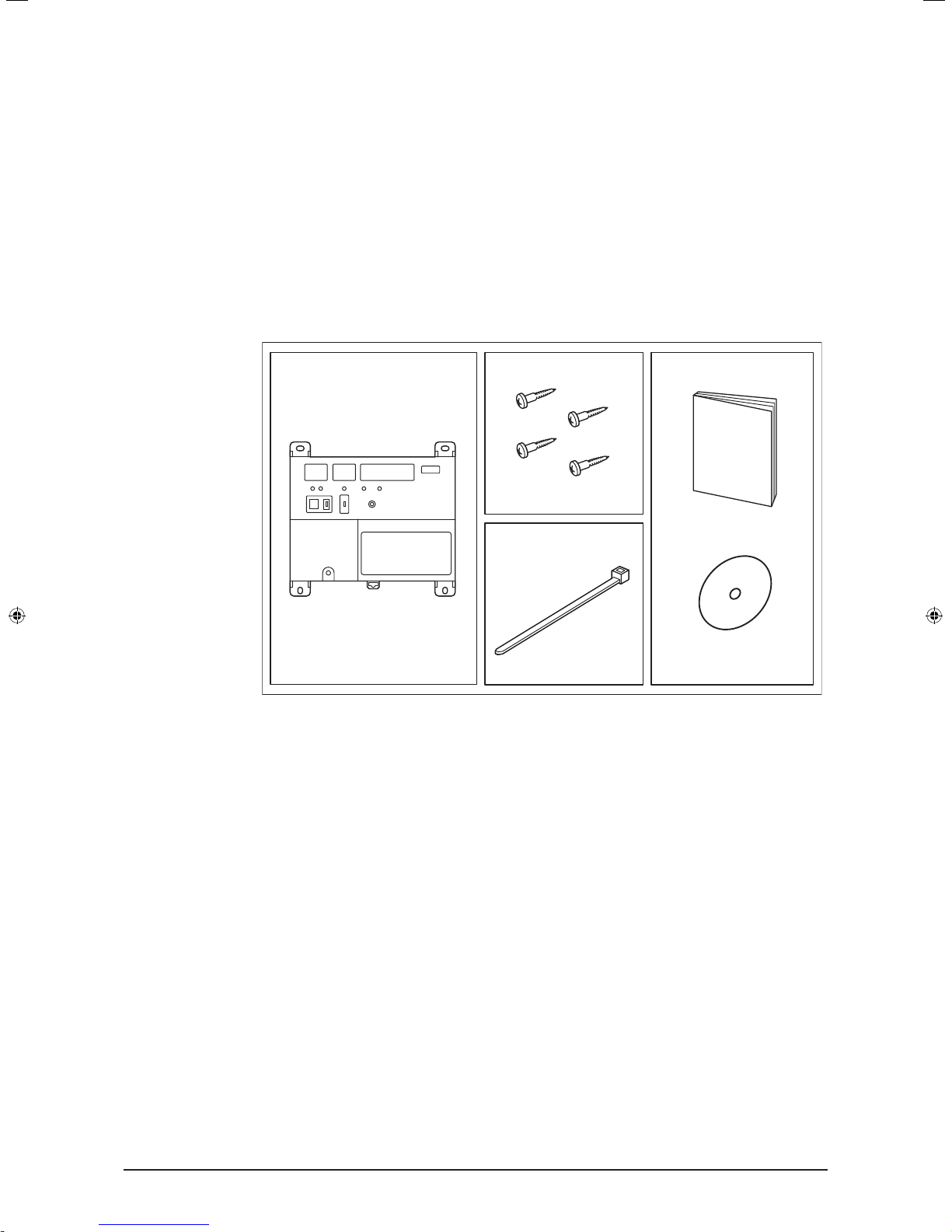
1.1 Checking that all accessories are included
Based on the following accessory list, check that all accessories for the iTM plus adaptor
are included. Should there be any missing or defective parts, contact your dealer.
<Accessories included with iTM plus adaptor>
A B
b-1
C
a-1
A (a-1) iTM plus adaptor body (1 pc.)
B (b-1) Round-head wood screw (φ3.5×16), 4 pcs.
C (c-1) Cable tie, 1 pc.
D (d-1) Installation manual (This manual), 1 pc. (d-2) Manual CD, 1 pc.
c-1
D
d-1
d-2
7

Installation Manual 3P291714-4
DCM601A72 iTM plus adaptor
English
1.2 Understanding external dimensions
• iTM plus adaptor body
6-5/16
5-1/2
5/32
1/4 1/4
5/32
2-13/32
2-11/162-21/32
5-7/8
5/32
1/4
5/32
1/4
5-11/32
1.3 Understanding where terminals are located
Understand the arrangement of terminals and switches on the unit and draw up an efcient work plan. For connection details including the cable type, terminal size, and wiring
precautions, refer to “2. Connection”.
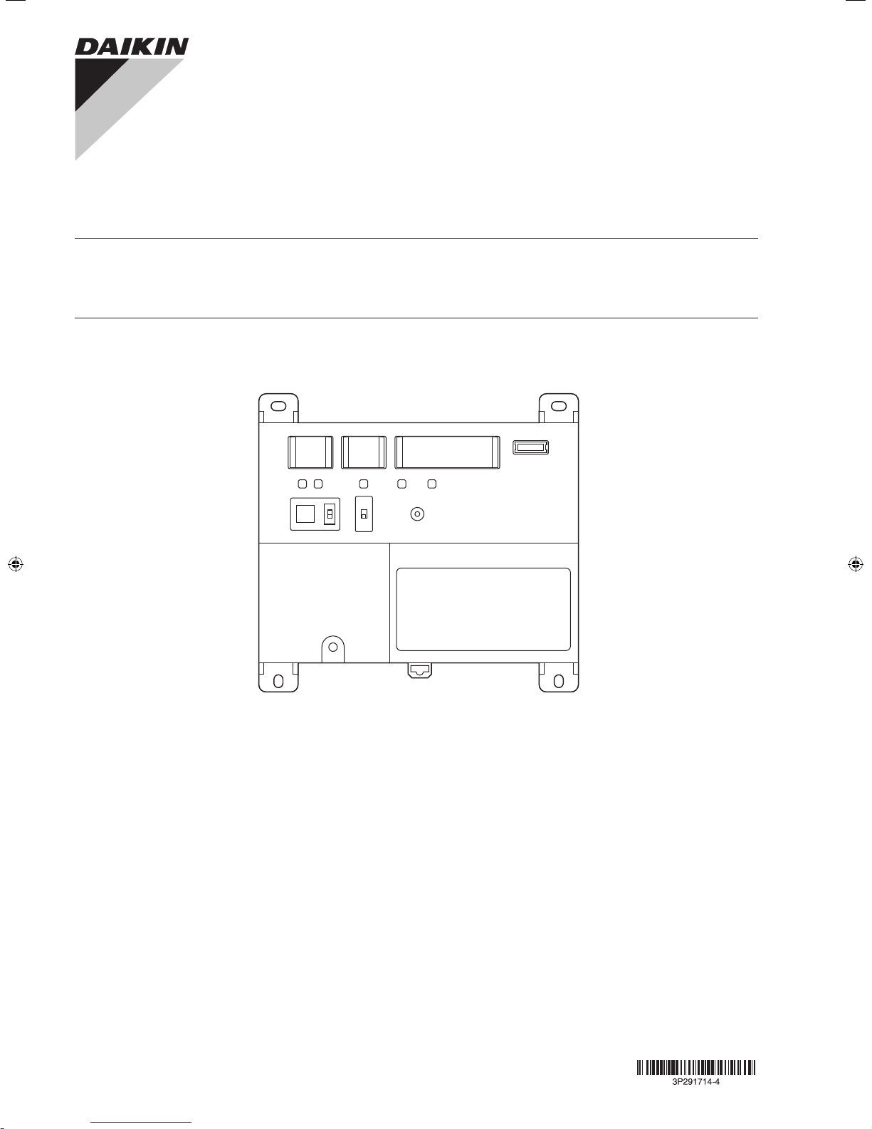
1.3.1 Front face of iTM plus adaptor
All the terminals used during installation are located on the front face of the iTM plus
adaptor. Note that only the power terminals are covered with a terminal cover for safety.
You can remove this cover by loosening a single screw.
In addition to these terminals, several switches and LEDs are also located on the front
face of the iTM plus adaptor.
4-23/32
2-1/16
2-13/32
(in.)
8
Installation Manual 3P291714-4
DCM601A72 iTM plus adaptor
English
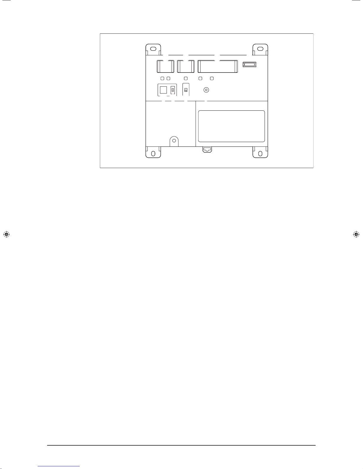
<Front face of iTM plus adaptor>
A
B C D
J K L M N
F
G H
LN
~
E
50/60Hz
100-240V
POWER
I
A [plus ADP IF] The terminals for connecting an intelligent Touch Manager or iTM plus
adaptor installed in parallel.
B [DIII] The communication line connection terminals for “DIII-NET”, which enables
communications with DAIKIN’s air conditioning equipment.
C [Di] The terminals for connecting an external signal input device for stopping air con-
ditioners in an emergency, or for connecting electric energy meters for calculating the
electricity usage of individual indoor air conditioning units.
D [RESERVE] No Use.
E [POWER] The power line connection terminals. These terminals are covered with a
protective cover. A power supply voltage of 24 VAC (at 60 Hz) is required. Near this
terminal block, there is a blue resin cable mount used for securing the power supply
cables with cable ties.
F [plus ADP ADDRESS] The switch for selecting the address of the iTM plus adaptor.
For each iTM plus adaptor, set a unique number between 2 to 8.
G [TERM] The switch used when multiple iTM plus adaptors are connected in parallel
for enabling the termination resistor on the furthest iTM plus adaptor from the intelligent Touch Manager.
H [DIII MASTER] The switch used when there are two or more DIII-NET centralized
controllers, such as intelligent Touch Managers, are connected for distinguishing
between the “MASTER” or the “SLAVE” controllers.
I [RESET//] The switch for restarting the iTM plus adaptor.
J [Tx] (Green) The indicator that indicates when on that data is being sent to the intel-
ligent Touch Manager.
K [Rx] (Orange) The indicator that indicates when on that data is being received from
the intelligent Touch Manager.
L [DIII MONITOR] (Yellow) The indicator that indicates when on that data is being com-
municated with DIII-NET.
M [CPU ALIVE] (Green) The LED that indicates that the CPU is operating normally. For
the relationship between the LED status and the unit’s operating condition, refer to
the “LED status and operation” table below.
N [ALARM] (Red) The LED that turns on or blinks in the event of an error. For the rela-
tionship between the LED status and the unit’s operating condition, refer to the “LED
status and operation” table below.
9
Installation Manual 3P291714-4
DCM601A72 iTM plus adaptor
English
The table below shows the status of the CPU ALIVE/ALARM LED when the iTM plus
adaptor is operating normally or failed.
NOTE
[LED status and operation table]
Operating condition CPU ALIVE ALARM
Normal Blink Off
Hardware failure Off On
Address failure On On
plus ADP IF communication failure On Blink
1.4 Determining installation place
Be sure to install the iTM plus adaptor in a place that meets the conditions described in
1.4.1 through 1.4.3.
1.4.1 Installation place and mounting direction
Note that the iTM plus adaptor must be installed in a place and in a mounting direction as
described below:
• Installation place: Indoor, inside control enclosure (which must be lockable or designed
to be opened only with a special tool)
• Mounting direction: Vertical only
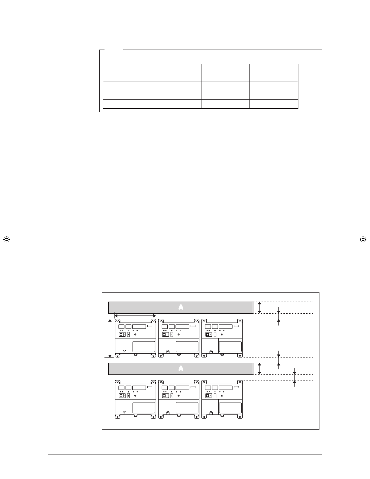
1.4.2 Required space
To install the iTM plus adaptor, the following space is required. Also note the following:
• Make sure that there is a minimum clearance of 25/32 in. between each unit and wiring
ducts.
• When installing two or more units side by side, they can be arranged without clearance
in the horizontal direction.
Required installation space
6-5/16
5-7/8
A
A
1-9/16
25/32
25/32
1-9/16
25/32
A Wiring duct
10
(in.)

Installation Manual 3P291714-4
DCM601A72 iTM plus adaptor
English
1.4.3 Environmental conditions
The installation environment must meet the following conditions:
• Ambient temperature: 14 to 122 °F
• Ambient humidity: 85% RH or less (without condensation)
11
 Loading...