


Model
DCM601A71
DCM601A72
User’s Manual
DCM601A73
DCM002A71
DCM008A71
SERVICE LAN
LAN SW
FRONT BACK
BACKUP
ON
SLAVE
D MASTER
OFF
MASTER
CPU ALIVE
RESET
LAN LINK
MONITOR
D MONITOR

Disclosure
To the User in USA
Part 15 of FCC
Note: This equipment has been tested and found to comply with the limits for a Class B
digital device, pursuant to part 15 of the FCC Rules. These limits are designed to provide
reasonable protection against harmful interference in a residential installation. This equipment generates, uses and can radiate radio frequency energy and, if not installed and used
in accordance with the instructions, may cause harmful interference to radio communications. However, there is no guarantee that interference will not occur in a particular installation. If this equipment does cause harmful interference to radio or television reception,
which can be determined by turning the equipment off and on, the user is encouraged to
try to correct the interference by one or more of the following measures:
- Reorient or relocate the receiving antenna.
- Increase the separation between the equipment and receiver.
- Connect the equipment into an outlet on a circuit different from that to which the receiver
is connected.
- Consult the dealer or an experienced radio/TV technician for help.
FCC CAUTION
Changes or modications not expressly approved by the party responsible for compliance
could void the user’s authority to operate the equipment.
To the User in CANADA
Canadian ICES-003
This Class B digital apparatus complies with Canadian ICES-003.
Cet appareil numérique de la classe B est conforme à la norme NMB-003 du Canada.
1

Safety Considerations
Read these SAFETY CONSIDERATIONS carefully before operating the controller.
Train the customer to operate and maintain the controller.
Inform customers that they should store this User’s Manual with the Installation Manual for future
reference.
Meanings of WARNING, CAUTION and NOTE Symbols:
Indicates a potentially hazardous situation which, if not avoided, could
WARNING
result in death or serious injury.
Indicates a potentially hazardous situation which, if not avoided, may
CAUTION
NOTE
result in minor or moderate injury.
It may also be used to alert against unsafe practices.
Indicates situation that may result in equipment or property-damage only
accidents.
• The following pictograms are used in this manual.
Never do. Always follow the instructions given.
Keep wet hands away. Keep water and moisture away.
WARNING
• Do not modify or repair the controller.
Consult your Daikin dealer for any modication or for repairs.
• Do not relocate or reinstall the controller by yourself.
Improper installation may result in electric shocks or re.
Consult your Daikin dealer to relocate or for any reinstallation.
• Do not use ammable materials (e.g., hairspray or insecticide) near the
controller.
Do not clean the product with organic solvents such as paint thinner.
The use of organic solvents may cause cracking, damaging the product, causing elec-
tric shocks, or re.
• Consult the dealer if the controller was submerged under water due to a
natural disaster, such as a ood or hurricane.
Do not operate the controller if it was submerged under water or a mal-
function, electric shock, or re can occur.
User’s Manual EM11A017
DCM601A71 intelligent Touch Manager
2

CAUTION
• Never disassemble the controller.
Touching the interior parts may result in electric shocks or re.
Consult your Daikin dealer for internal inspections and adjustments.
• Do not allow children to play with the controller to avoid causing damage
to the product.
• Do not touch the controller buttons with wet ngers.
Touching the buttons with wet ngers can cause an electric shock.
• Do not wash the controller.
Doing so may cause electric leakage and result in electric shocks or re.
• Never let the controller to get wet.
Water can cause damage to the controller, and may cause an electric shock or re.
NOTE
• Never press the button of the controller with a hard, pointed object.
The controller may be damaged.
• Never pull or twist the electric wire of the controller.
It may cause the unit to malfunction.
• Do not wipe the controller operation panel with benzine, thinner, chemical
dustcloth, etc.
The panel may get discolored or the coating peeled off. If it is heavily dirty, soak a
cloth in water-diluted neutral detergent, squeeze it well and wipe the panel clean. And
wipe it with another dry cloth.
3
User’s Manual EM11A017
DCM601A71 intelligent Touch Manager

Contents
Safety Considerations ....................................................................2
System Overview ............................................................................ 8
1. About the iTM (intelligent Touch Manager) ...................................................... 8
1-1 Main Features ..................................................................................................................... 8
1-2 System Conguration ......................................................................................................... 9
1-3 What is a Management Point/Area? ................................................................................. 10
• What is a management point? ......................................................................................10
• What is an area? ........................................................................................................... 10
1-4 Touch Panel Operation Method ........................................................................................ 12
1-5 Dialog Operation ............................................................................................................... 16
• Text /Password input dialog operation .......................................................................... 16
• Time input dialog operation ...........................................................................................19
• Numerical input dialog operation .................................................................................. 20
Quick Reference ...........................................................................22
2. Simple Operations ...........................................................................................22
2-1 Displaying the List of Areas and Management Points ...................................................... 22
2-2 Displaying Areas and Management Points ....................................................................... 22
2-3 Starting/Stopping Areas and Management Points ............................................................ 23
2-4 Setting up the Operation Mode for an Indoor Unit ............................................................ 24
2-5 Setting up the Setpoint, Fan Speed, and Airow Direction for an Indoor Unit .................. 25
2-6 Enabling/Disabling Remote Controller .............................................................................. 27
2-7 Setting up the Operation Mode and Ventilation Amount for Ventilator .............................. 28
2-8 Performing Operations with the Menu List Screen ........................................................... 28
• Checking the schedule .................................................................................................. 29
• Checking settings such as Area Name, Detailed Info., and Icon .................................. 30
• Checking settings such as Mgmt. Point Name, Detailed Info., and Icon ....................... 30
• Setting up the time ........................................................................................................ 31
• Checking the history ..................................................................................................... 32
Names and Functions ..................................................................33
3. Names and Functions of Each Part ................................................................ 33
3-1 Front Panel and Side View ................................................................................................ 33
User’s Manual EM11A017
DCM601A71 intelligent Touch Manager
4

4. Detailed Screen Description ...........................................................................35
4-1 Setup Screen Structure .................................................................................................... 35
4-2 Standard View (Icon) Screen ............................................................................................ 37
• Detailed Setup Screen .................................................................................................. 40
• Detailed Information Screen ......................................................................................... 46
4-3 Standard View (List) Screen ............................................................................................. 47
4-4 Layout View (Optional) Screen ......................................................................................... 50
4-5 Menu List Screen .............................................................................................................. 52
• Automatic Ctrl. Tab ........................................................................................................ 52
• System Settings Tab ..................................................................................................... 54
• Operation Mgmt. Tab ..................................................................................................... 56
• Energy Navigator Tab .................................................................................................... 57
4-6 Information Screen ........................................................................................................... 58
• Legend Tab ................................................................................................................... 58
• Contact Tab ................................................................................................................... 60
Using Standard Functions ........................................................... 61
5. Setting up the Automatic Control ...................................................................61
5-1 Setting up a Schedule....................................................................................................... 61
• Setting up a schedule program ..................................................................................... 61
• Detailed screen and button descriptions ....................................................................... 72
5-2 Setting up the Timer Extension Function .......................................................................... 97
5-3 Setting up the Auto Changeover ....................................................................................... 99
• Creating and editing an Auto Changeover group ........................................................ 101
• Setting up the changeover conditions ......................................................................... 103
• Applying the Auto Changeover function ...................................................................... 105
5-4 Checking an Emergency Stop ........................................................................................ 107
6. System Settings .............................................................................................109
6-1 Setting up an Area .......................................................................................................... 109
• Creating and deleting an area .....................................................................................109
• Moving an area ........................................................................................................... 113
• Registering a management point or area to an area .................................................. 114
• Naming and setting up the detailed information of an area ........................................ 117
• Setting up the interval for sequential start/stop ........................................................... 118
• Setting up icons ..........................................................................................................119
• Saving and loading the area data CSV le ................................................................. 120
6-2 Setting up a Management Point .....................................................................................121
5
User’s Manual EM11A017
DCM601A71 intelligent Touch Manager

6-3 Setting up and Changing the Password .......................................................................... 123
6-4 Setting up Maintenance and Checking ........................................................................... 125
6-5 Setting up and Changing the Locale............................................................................... 126
6-6 Setting up and Changing the Time .................................................................................128
6-7 Setting up and Changing the Screensaver ..................................................................... 129
6-8 Setting up and Changing the Hardware Settings ............................................................ 130
6-9 Setting up and Changing the Conrm Operation ............................................................ 131
6-10 Calibrating the Touch Panel ......................................................................................... 132
6-11 Backing up ................................................................................................................... 133
6-12 Viewing the Version Information ................................................................................... 134
7. Data Management ..........................................................................................135
7-1 Checking and Outputting History .................................................................................... 135
7-2 Outputting Function Settings .......................................................................................... 137
Operating Optional Functions ................................................... 147
8. Setting up Automatic Control Functions .....................................................147
8-1 Setting up the Setback .................................................................................................... 147
8-2 Setting up the Interlocking Control .................................................................................. 153
• Interlocking Control Restrictions ................................................................................. 156
• Setting up an interlocking program ............................................................................. 158
• Detailed screen and button descriptions ..................................................................... 166
8-3 Setting up the Emergency Stop ...................................................................................... 188
• Releasing the Emergency Stop ..................................................................................191
8-4 Setting up the Temperature Limit .................................................................................... 192
8-5 Setting up the Sliding Temperature Function .................................................................. 197
8-6 Setting up the Heating Mode Optimization Function ...................................................... 203
9. System Settings .............................................................................................205
9-1 Network Settings ............................................................................................................ 205
9-2 Web Access Settings and Remote Management ........................................................... 208
• Registering Web users ................................................................................................ 209
• Logging in/out to/from a PC ........................................................................................212
• Web Remote Management Screen ............................................................................. 213
9-3 Setting up the E-Mail Error Report ................................................................................. 216
• Setting up the Mail Server ........................................................................................... 216
• Setting up the recipient E-mail address and sending an E-mail .................................219
User’s Manual EM11A017
DCM601A71 intelligent Touch Manager
6

Operating Optional Maker Functions .......................................223
10. Power Proportional Distribution ...............................................................223
10-1 Power Proportional Distribution Function .................................................................. 223
• Setting up the data collection period ........................................................................... 223
• Collecting data and outputting the Power Proportional Distribution results ................ 224
11. Energy Navigator ........................................................................................ 226
11-1 Energy Navigator Function ........................................................................................ 226
• Energy Budget/Actual Management ........................................................................... 229
• Equipment operation management (Deviation from the operation plan) ..................... 249
• Data output function .................................................................................................... 265
iTM integrator Explanation ........................................................273
12. iTM integrator..............................................................................................273
12-1 iTM integrator ............................................................................................................ 273
• Detailed screen and button descriptions ..................................................................... 274
• Cautions when using the iTM integrator ..................................................................... 282
Maintenance ................................................................................ 286
13. Maintenance ................................................................................................ 286
13-1 Resetting the Filter Sign ............................................................................................ 286
13-2 Maintaining the LCD display ...................................................................................... 287
Useful Information ...................................................................... 288
14. Troubleshooting..........................................................................................288
14-1 Before Having the Product Serviced ......................................................................... 288
14-2 Turning ON/OFF the Internal Battery ......................................................................... 299
14-3 Error Information Function ......................................................................................... 300
15. Hardware Specications ............................................................................ 302
15-1 iTM Hardware Specications ..................................................................................... 302
15-2 Peripheral Equipment Specications ......................................................................... 303
15-3 Copyright and Trademarks ......................................................................................... 303
Appendix .....................................................................................304
7
User’s Manual EM11A017
DCM601A71 intelligent Touch Manager

System Overview
1. About the iTM (intelligent Touch Manager)
1-1 Main Features
•
iTM is an advanced central controller operated by using a 10.4” touch panel. It allows you to easily monitor
as well as operate air conditioners and generic equipment connected to the iTM from the touch panel.
• One iTM can monitor and control a maximum of 64 groups of indoor units (128 units), including
Ventilator. The iTM can be expanded with up to seven iTM plus adaptors, which similarly to the
iTM, can connect a maximum of 64 groups of indoor units (128 units); that is, with one iTM you
can control and monitor a maximum of 512 groups of indoor units (1024 units).
A group of indoor units refers to the following:
(1) One indoor unit without remote controller
Indoor unit
No remote controller
(3) Up to 16 indoor units controlled as group with one or two remote controllers
•
The iTM allows you to dene privileges for Users and Managers, so that you can set up and manage them according
(2) One indoor unit controlled with one or two remote controllers
or
Remote controller Remote controller
Up to 16Up to 16 Two remote controllerRemote controller
to their respective privileges. Furthermore, by connecting the iTM with computers in a LAN, you can set up Web
Remote Management and allow a maximum of 4 managers and 16 users to simultaneously access the iTM, and if a
connection to the Internet is available, then, you can monitor and operate the iTM remotely, via the Internet.
• The iTM allows you to schedule the operation of each air conditioner in detail.
You can set up an annual schedule by setting up a schedule by the day of the week and dening
Special Days such as extra holidays.
Changes by the season are achieved by setting up a validity period to programs.
By using optional functions, you can display the oor plan of individual buildings and the like as background
•
on the iTM monitoring screen, and monitor and operate by viewing the actual layout of the air conditioners.
• You can use Interlocking Control to start/stop air conditioners in conjunction with other equipment
or Setback function to save energy.
You can use Power Proportional Distribution function (option software) to distribute the electric bill among
•
tenants or the Energy Navigator function (option software) to manage the energy consumption systematically.
• By connecting a USB memory to the iTM, you can output billing data, budget/actual energy
consumption data, function settings, history data, etc. to a CSV le.
NOTE
• Periodical data saving is recommended in order to prevent loss of your important data due
to an accidental problem.
User’s Manual EM11A017
DCM601A71 intelligent Touch Manager
8
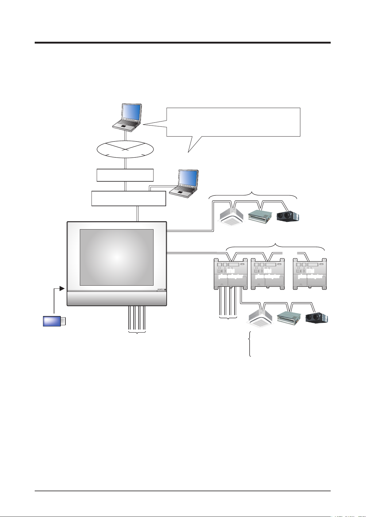
1-2 System Conguration
Web Remote Management
Intranet/Internet
ROUTER
HUB/SWITCH/ROUTER/....
LAN port
Web Remote Management possible from networkconnected PC
Maximum 4 administrators and 16 users can log in
at the same time
Web Remote Management
Up to 64 groups
D3net port
USB port
USB memory
iTM
Port 1:
Port 2~4:
RS485
(Expansion
adapter port)
Di/Pi port
Emergency Stop signal input
Power meter pulse input
Input signal (contact) such as
power outage signal
iTM
iTM
plus adaptor
plus adaptor
Di/Pi port
Port 1~4:
Up to 7
. . .
iTM
iTM
plus adaptor
plus adaptor
plus adaptor
plus adaptor
D3net
Emergency Stop signal input
Power meter pulse input
Input signal (contact) such as
power outage signal
iTM
iTM
9
User’s Manual EM11A017
DCM601A71 intelligent Touch Manager

1-3 What is a Management Point/Area?
What is a management point?
A management point is the target equipment monitored and operated using the iTM.
The types of management points that can be controlled by iTM are as follows:
Indoor, Ventilator, Dio, Analog, Pulse, and Outdoor, Chiller
What is an area?
An area is a hierarchical group into which management points, monitored and operated by the iTM,
are classied. You can populate an area with member areas and management points. An All area,
to which you cannot manually register or delete members from, is provided by default.
Maximum number of areas that can be created: 650 (All excluded)
Example:
All Area
Total number of
management points
that can be registered
in Top areas :
1300 (All excluded)
Maximum number of hierarchal levels that can be created: 10 levels
Top
Area Management point
Lavatory
Lavatory Indoor unit
1 F
All
Meeting room
Meeting room indoor-unit
Office indoor unit
Levels Level 1 2
1 F
Indoor unit
3
Maximum number
of management
points and areas
that can be
registered in
one area
: 650
NOTE
Registered management points are automatically registered in the folder for the corresponding
management point type set up under All.
User’s Manual EM11A017
DCM601A71 intelligent Touch Manager
10

You can register a management point in two or more areas. However, you cannot register the same
management point two or more times in one area. You cannot register the same area in two or
more areas either.
Example:
Areas/Management
points displayed when
Top is touched.
Area Management point
Top
Level 1 Level 2 Level 3 Level 4 ... Level 10
All
Indoor
Ventilator
Dio
Analog
Pulse
Outdoor
Chiller
Building A
1F North
1F South
Meeting
Room
Aisle
•Registered management points automatically belong to an
area based on their
type.
•Areas with management points of nonexisting types are not
displayed.
The same management point cannot be
registered with the
same area.
Meeting
Room A
Management point A
Management point A
Aisle
Management point A
The same area cannot
be registered repeatedly.
11
User’s Manual EM11A017
DCM601A71 intelligent Touch Manager

1-4 Touch Panel Operation Method
Operation is possible by touching the panel with your ngers or a touch pen. Be sure not to use
sharp edged items as this could damage the touch screen permanently.
<Standard View (Icon) Screen>
(3)
(1)
<Detailed Setup dialog>
(3)
(2)
(3)
(6)
(8)
(5)
(4)
)
(5)
(7)
The following describes how the text on each component, displayed on screen, looks like in normal
state, when it is selected (it has been touched), or is grayed out. (* For components not shown in
the Standard view above, see the respective detailed description page.)
User’s Manual EM11A017
DCM601A71 intelligent Touch Manager
12

(1) Icon of centrally monitored management point/area
Unselected status Selected status
(2) List, scroll bars, and sorting
List image
• Scroll bars appear when there are hidden lines and columns.
• To display hidden lines and columns, press
, or slide the scroll bars.
• To display truncated column text, slide the column separation.
• When sorting is enabled, touch the header to sort the column according to the sequence shown
in the gure below
Initial state Ascending order Descending order
(3) Button
Normal status
Pressed status
Grayed out status
13
With tool tip
User’s Manual EM11A017
DCM601A71 intelligent Touch Manager

NOTE
• Components such as buttons and check boxes are grayed out when not all the conditions for
operating the particular function/option for the management point/area are satisfied.
Operation, such as touch and select a grayed out component, is not possible.
• “...” is displayed on buttons and the like when the label text is truncated due to space
availability.
To display the label text completely, touch the component for a while. A tool tip with the
complete text will appear.
(4) Radio button
Selected status Unselected status Grayed out status
(5) Check box
With tool tip
Selected status Unselected status Grayed out status
With tool tip
User’s Manual EM11A017
DCM601A71 intelligent Touch Manager
14

(6) Combo box
(7) Text box
Closed status
Open status
When the list opens downward
Text box (When unfocused) Text box (When focused)
Grayed out status
Open status
(When a row is selected)
Cursor
Indicates the position where the next character
will be entered.
When the list opens upward
With tool tip
Open status
(8) Spin box
Closed status
Grayed out status
(When an
intermediate value
is selected)
(When the
maximum value
is selected)
Open status
(When the
minimum value
is selected)
15
User’s Manual EM11A017
DCM601A71 intelligent Touch Manager

1-5 Dialog Operation
Text /Password input dialog operation
(2)
(1)
(6)
(7) (8)
(5)
(3)
(4)
(1) Character key buttons
Key buttons for entering characters.
(2) Input area text box
Displays the entered characters. For the Password input dialog, it displays asterisks (*).
(3) Shift key toggle button
Toggles between upper and lower case.
Shift key
pressing
Shift key
pressing
(4) Right and left arrow buttons
Moves right and left the cursor in the input area text box.
User’s Manual EM11A017
DCM601A71 intelligent Touch Manager
16

(5) Character input range label
Displays three types of information regarding the number of characters that can be entered.
Remaining: Indicates the difference between the number of characters entered and the maximum
permitted by the function
Exceeded: Indicates the number of characters entered in excess from the maximum permitted
Missing: Indicates the number of characters still necessary to comply with the minimum required
(6) Keyboard switch combo box
Toggles the keyboard between Special and Alph nm ltrs.
Special: Sets the keyboard to special keyboard
Alph nm Itrs: Sets the keyboard to alphanumeric keyboard
Not displayed for the Password input dialog.
To toggle between upper and lower case, use the Shift key.
Shift key
pressing
Shift key
pressing
(7) OK button
Touching this button commits the input.
(8) Cancel button
Touching this button cancels the edit and closes the screen.
17
User’s Manual EM11A017
DCM601A71 intelligent Touch Manager

NOTE
• Grayed out characters are unavailable for input.
• When Chinese, Japanese or Korean is set as the iTM display language, a button to display
the input list appears. Touch the button to display a list of frequently used words and select
the word to input. Select a word and commit the selection by pressing the OK button. The
selected word is displayed in the input area text box. Not displayed for the Password input
dialog.
User’s Manual EM11A017
DCM601A71 intelligent Touch Manager
18

Time input dialog operation
(2)
(4)
(1)
(5)
(3)
(7)(6)
(1) Number key button
Key buttons for entering numeric values.
(2) Input area text box
Displays the entered numeric values. Touch the text box and enter the required numeric value. The
input area text box changes the display pattern among “year month day hour minute second”, “year
month day”, and “hour minute” depending on the entered data.
(3) Up/Down button
Increases or decreases the numeric value selected in the input area text box (2) by +1, +10, –1, or
–10.
(4) AM/PM setting combo box
Species whether the time is AM or PM when time is indicated using 12-hour clock. This combo
box is not displayed when 24-hour clock is set in the System Settings.
(5) Input range label
Displays the range of values that can be entered.
(6) OK button
Touching this button commits the input.
(7) Cancel button
Touching this button cancels the edit and closes the screen.
19
User’s Manual EM11A017
DCM601A71 intelligent Touch Manager

Numerical input dialog operation
(8)
(4)
(9)
(5)
(6)
(1)
(7)
(3) (2)
(10)
(11)
(1) Number key button
Key buttons for entering numeric values.
(2) Decimal point key button
Press this button to enter a decimal point.
(3) +/– key button
Press this button to change the sign of a numeric value. Adds a minus sign before a positive value
while for a negative value, deletes the minus sign and makes the value positive.
(4) Back button
Deletes one digit at a time from the last number displayed in the input area text box.
(5) Clear button
Completely deletes the numeric value displayed in the input area text box.
(6) Up/Down step radio button
Species the step by which the Up/Down button increases/decreases when pressed. You can only
select buttons with higher step values than the minimum step dened for the value to be input, see
frame (9).
(7) Up/Down button
Increases or decreases the numeric value by the step specied in the Up/Down step radio button.
(8) Input area text box
Displays the entered numeric values. You can input up to 10 characters.
User’s Manual EM11A017
DCM601A71 intelligent Touch Manager
20

(9) Input range label
Displays the range of values that can be entered.
(10) OK button
Touching this button commits the input.
(11) Cancel button
Touching this button cancels the edit and closes the screen.
21
User’s Manual EM11A017
DCM601A71 intelligent Touch Manager

Quick Reference
2. Simple Operations
2-1 Displaying the List of Areas and Management Points
(1)
(2)
(1) Touch the List button.
(2) The List View screen with the area and indoor unit names, the operation mode, setpoint, and
fan speed information appears.
(For detailed operation, see page 47.)
2-2 Displaying Areas and Management Points
(1)
(2)
(1) Displays the hierarchical level of the current area and indoor unit.
(2) Touch the Down button to move into the selected area and display the areas and management
points included there.
User’s Manual EM11A017
DCM601A71 intelligent Touch Manager
22

(3)
(3) Touch the Up button to move one level up from the currently selected one.
(For detailed operation, see page 37.)
2-3 Starting/Stopping Areas and Management Points
(1)
(2)
(1) Select the area or management point you want to start or stop.
(2) Selecting “Start” in the On/Off combo box starts the selected area or management point while
selecting “Stop” stops the selected area or management point. The icon turns green or red
(depending on the system settings) when the selected area or management point has been started
while the icon turns gray when it is stopped.
(3) (3)
(3) When Conrm is “enabled” in the system settings, a conrmation dialog appears accordingly.
Press the Yes button to commit. (For detailed operation, see page 131.)
23
User’s Manual EM11A017
DCM601A71 intelligent Touch Manager

2-4 Setting up the Operation Mode for an Indoor Unit
(4)
(1)
(3)
(2)
(5)
(1) Select the indoor unit for which you want to set up the operation mode.
(2) Touch the Setting button and display the Detailed Setup screen.
(3) Select the A/C tab.
(4) Select the Operation Mode check box and select Fan, Cool, Heat, Dependent, Automatic, or
Dry from the combo box.
(5) Touch the OK button to commit and close the screen.
(For detailed operation, see page 42.)
User’s Manual EM11A017
DCM601A71 intelligent Touch Manager
24

2-5 Setting up the Setpoint, Fan Speed, and Airflow Direction for an
Indoor Unit
(3)
(1)
(2)
(1) Select the indoor unit for which you want to set up the setpoint, fan speed, and airow direction.
(2) Set up the setpoint in the Setpoint spin box, and the Fan Speed using the
(Low) (Middle) (High)
(Automatic)
buttons.
NOTE
Available fan speed settings depend on the indoor unit.
(3) You can also set up the setpoint and fan speed in the Detailed Setup screen. (For the operation
to display the Detailed Setup screen, see (4) To set up the airow direction.)
25
User’s Manual EM11A017
DCM601A71 intelligent Touch Manager
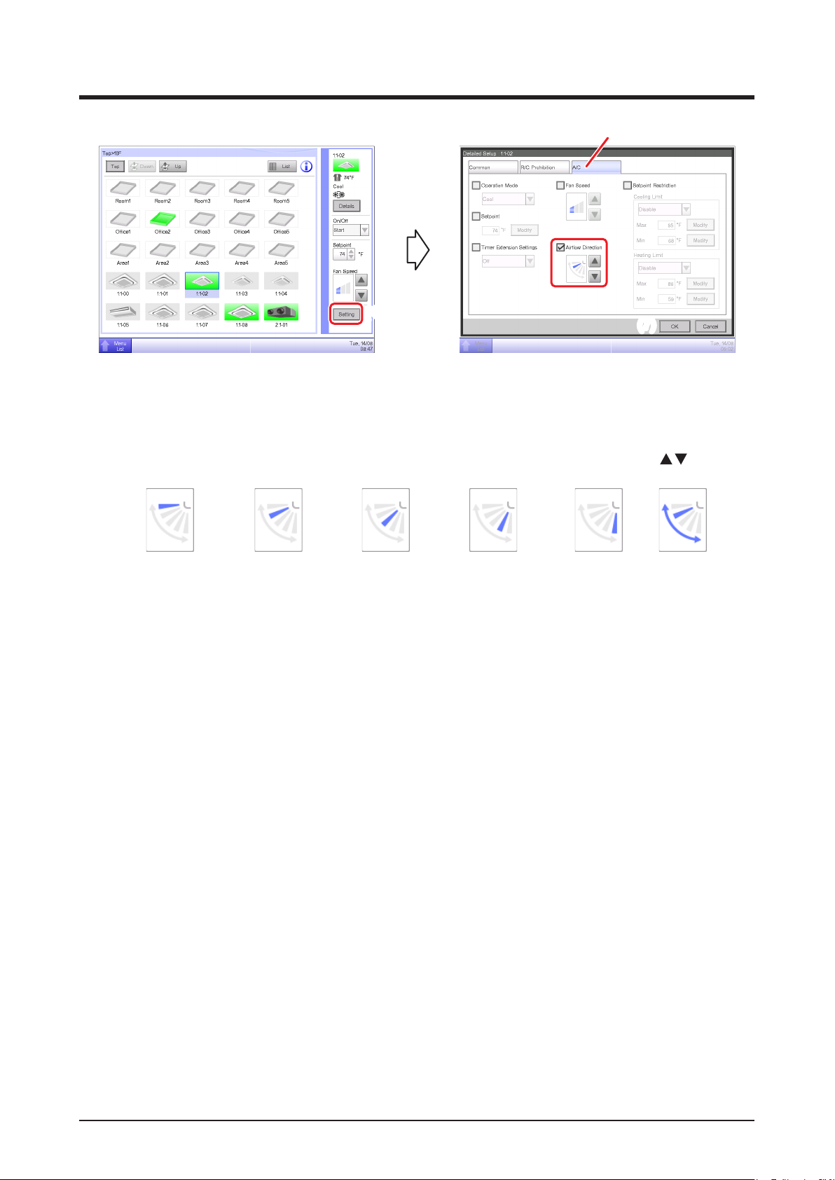
(6)
(5)
(4)
(7)
(4) To set up the airow direction, touch the Setting button and display the Detailed Setup screen.
(5) Select the A/C tab.
(6) Select the Airow Direction check box and set up the Airow Direction using the
<
Airflow direction 0
> <
Airflow direction 1
> <
Airflow direction 2
> <
Airflow direction 3
> <
Airflow direction 4
buttons.
> <Swing>
(7) Touch the OK button to commit and close the screen. (For detailed operation, see page 42.)
User’s Manual EM11A017
DCM601A71 intelligent Touch Manager
26

2-6 Enabling/Disabling Remote Controller
(3)
(4) (a)
(5)
(1)
(4) (b)
(5)
(2)
(4) (c)
(5)
(6)
(1) Select the area or management point for which you want enable/disable remote controller.
(2) Touch the Setting button and display the Detailed Setup screen.
(3) Select the R/C Prohibition tab.
(4) You can permit/prohibit the following remote controller operations: (a) start/stop, (b) set up the
operation mode, and (c) set up the setpoint.
(5) Select the check box of the operation you want to set up and select its detail from the radio
button.
(6) Touch the OK button to commit and close the screen.
(For detailed operation, see page 41.)
27
User’s Manual EM11A017
DCM601A71 intelligent Touch Manager

2-7
Setting up the Operation Mode and Ventilation Amount for Ventilator
(3)
(4)
(5)
(1)
(2)
(6)
(1) Select the Ventilator for which you want to set up the operation mode and ventilation amount.
(2) Touch the Setting button and display the Detailed Setup screen.
(3) Select the Ventilator tab.
(4) Select the check box for Ventilation Mode and select Automatic, ERVentilation, or Bypass from
the combo box.
(5) Select the check box for Ventilation Amount and select Auto(normal), Low(normal),
High(normal), Auto(fresh up), Low(fresh up), or High(fresh up) from the combo box.
(6) Touch the OK button to commit and close the screen.
(For detailed operation, see page 44.)
2-8 Performing Operations with the Menu List Screen
The Menu List screen allows you to check schedules, set up areas/management points, set up the
time, check history, etc.
(1)
(1) Touch the Menu List button and display the Menu List screen.
(For detailed operation, see page 52.)
User’s Manual EM11A017
DCM601A71 intelligent Touch Manager
28
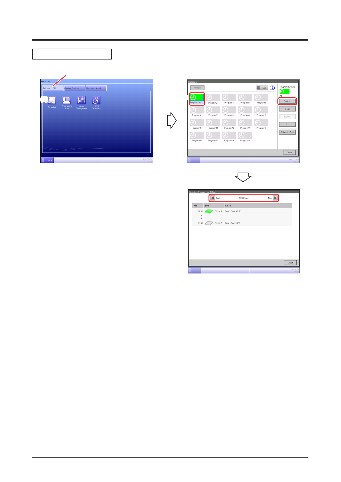
Checking the schedule
(1)
(2)
(3)
(4)
(5)
(1) Select the Automatic Ctrl. tab on the Menu List screen.
(2) Touch the Schedule button and display the Schedule screen.
(3) Select the schedule program to check.
(4) Touch the Conrm button on the Schedule screen and display the Conrm screen.
(5) Select the date for which you want to check the schedule.
(For detailed operation, see page 72.)
29
User’s Manual EM11A017
DCM601A71 intelligent Touch Manager
 Loading...