

Daikin DCM014A51 Design Manual

DG_DCM014A51_02-17
Intelligent Touch Manager
BACnet® Server Gateway
DCM014A51
DESIGN GUIDE

Contents
Part 1. Overview .......................................................................................................................................... 6
1. DCM014A51 iTM BACnet® Server Gateway ......................................................................................... 6
1.1 Features ........................................................................................................................................ 6
1.2 BACnet® Compatibility .................................................................................................................. 7
1.3 System Outline .............................................................................................................................. 7
2. VRV System Overview ........................................................................................................................... 8
2.1 Types of Daikin VRV Systems ........................................................................................................ 8
2.2 DIII-Net System and Group Addresses ......................................................................................... 9
2.3 Remote Controller Group and Group Address ............................................................................. 9
2.4 Commanding Mode Change for Heat Recovery and Heat Pump Systems ................................. 11
2.5 Changeover Master and Secondary (Non-Master) Indoor Units................................................ 12
2.6 Indoor Unit Logic ........................................................................................................................ 12
3. iTM Overview ...................................................................................................................................... 14
3.1 Indoor Unit Management Point ................................................................................................. 14
3.2 Automatic Control ...................................................................................................................... 16
Part 2. Functional Specifications ............................................................................................................... 21
1. Introduction ........................................................................................................................................ 21
2. Network Topology .............................................................................................................................. 21
2.1 Visualization of Each Device on the BACnet® Network .............................................................. 21
2.2 BACnet® Network Number ......................................................................................................... 22
2.3 Device ID (Device Instance Number) .......................................................................................... 22
2.4 What is a MAC Address? ............................................................................................................. 22
2.5 MAC Address of a Virtual BACnet® Device ................................................................................. 22
3. iTM and BACnet® Server Gateway Logic ............................................................................................ 23
3.1 BACnet® Virtual Router Function ............................................................................................... 23
3.2 iTM BACnet® Server Gateway Point Logic in the iTM................................................................. 23
4. VRV System Monitor/Control Objects ................................................................................................ 24
4.1 Member Objects ......................................................................................................................... 24
4.2 Indoor Unit Device ...................................................................................................................... 24
4.3 System Control Device ................................................................................................................ 27
4.4 Restrictions ................................................................................................................................. 27

5. Properties ........................................................................................................................................... 30
5.1 Device Object Type ..................................................................................................................... 30
5.2 System Control Device ................................................................................................................ 32
5.3 Analog Input Object Type ........................................................................................................... 34
5.4 Analog Value Object Type ........................................................................................................... 35
5.5 Binary Input Object Typed .......................................................................................................... 36
5.6 Binary Output Object Type ......................................................................................................... 37
5.7 Binary Value Object Type ........................................................................................................... 38
5.8 Multi-State Input Object Type .................................................................................................... 39
5.9 Multi-State Output Object Type ................................................................................................. 40
5.10 Multi-State Value Object Type ................................................................................................... 41
6. Error Response in BACnet® Communication ...................................................................................... 42
7. Detailed Description of Objects .......................................................................................................... 43
7.1 Specifications Common to All Objects ........................................................................................ 43
7.2 Individual Object Specifications .................................................................................................. 44
7.3 Individual System Control Object Specifications ........................................................................ 61
8. Report Function .................................................................................................................................. 63
8.1 COV Notification ......................................................................................................................... 63
9. Error Codes ......................................................................................................................................... 64
10. PICS ................................................................................................................................................... 66
11. BACnet® Interoperability Building Blocks Supported (BIBBs) ........................................................... 70
Part 3. Commissioning Procedure ............................................................................................................. 74
1. Site Visit .............................................................................................................................................. 74
1.1 Obtaining Object Information .................................................................................................... 74
2. Foreign Device .................................................................................................................................... 79
2.1 Foreign Device Setting ................................................................................................................ 79
2.2 Typically Not Changed Unless Requested by the BMS ............................................................... 79
3. BACnet® Point List .............................................................................................................................. 80
What is a point list? ............................................................................................................................ 80
3.1 System Control (one per system) ............................................................................................... 80
3.2 Indoor Unit Points (for each indoor unit) ................................................................................... 81
4. Commissioning the BACnet® Server Gateway on the iTM ................................................................. 81
4.1 The iTM BACnet® Server Gateway Activation ............................................................................ 82
4.2 CSV Configuration ....................................................................................................................... 83
5. Connecting the test operation PC and iTM via the cross cable or the hub/switch
using 100BASE-TX straight cable ........................................................................................................ 89
5.1 Connecting a Test PC to the iTM ................................................................................................ 89
5.2 Configuring iTM Network Settings.............................................................................................. 89

5.3 How to configure PC Network Settings ...................................................................................... 89
5.4 Return the IP address of the Test PC to the Original Address After the Test Operation ........... 90
6. Reference ............................................................................................................................................ 91
6.1 Possible Causes for Unconnected iTM and Test Operation PC .................................................. 91
6.2 How to Execute PING .................................................................................................................. 91
7. Handover to BMS ................................................................................................................................ 92
7.1 CSV File ....................................................................................................................................... 92
7.2 Network Settings ........................................................................................................................ 92
7.3 Ask the BMS Integrator to Discover the BACnet® Points from the iTM. .................................... 92
7.4 Unable to Auto-Discover BACnet® Points .................................................................................. 92
7.5 Final Review ................................................................................................................................ 92
Part 4. Programming Guide ....................................................................................................................... 93
1. Typical Requirements ......................................................................................................................... 93
1.1 Typical Indoor Unit Schedule Set by BMS Master Schedule ....................................................... 93
2. How to Program .................................................................................................................................. 93
2.1 Setpoints ..................................................................................................................................... 93
2.2 Setpoint Range Limitation .......................................................................................................... 94
2.3 Auto-Changeover Configuration ................................................................................................. 94
2.4 Schedule ..................................................................................................................................... 94
2.5 Timed Override ........................................................................................................................... 94
2.6 Remote Controller Prohibits ....................................................................................................... 94
3. Notes ................................................................................................................................................... 95
3.1 Indoor Unit EEPROM .................................................................................................................. 95
3.2 Priority Array............................................................................................................................... 95
Part 5. Installation Manual ....................................................................................................................... 96
1. Installation .......................................................................................................................................... 96
1.1 Understanding theLocation of Terminals and Switches ............................................................. 96
1.2 Rear Face .................................................................................................................................... 96
1.3 Front Panel.................................................................................................................................. 97
1.4 Side Face ..................................................................................................................................... 98
1.5 Environmental Conditions .......................................................................................................... 98
2. Electrical Wiring .................................................................................................................................. 99
2.1 Removing Wiring Cover from Rear Face ..................................................................................... 99
2.2 Connecting DIII-Net-Compatible Air Conditioning Equipment ................................................... 99
2.3 Wiring Specifications ................................................................................................................ 100

3. Basic Setup of Intelligent Touch Manager ........................................................................................ 105
3.1 Setting Backup Battery to ON ................................................................................................... 105
3.2 Turning On Power Supply to iTM and Air Conditioners ........................................................... 106
Appendix A. BACnet® Gateway (DMS502B71) and iTM Protocol Comparison ................................... 107
1. Functions Removed from BACnet® Gateway............................................................................... 107
2. Changes from the BACnet® Gateway .......................................................................................... 108
Appendix B. Supported Models and Monitoring Control Items .......................................................... 111
Appendix C. iTM Specifications, Dimensions, and System Wiring ....................................................... 113
1. Specifications ............................................................................................................................... 113
2. Dimensions................................................................................................................................... 113
3. System Configuration and Wiring ................................................................................................ 115
Part 1. Overview
Part 1. Overview
1. DCM014A51 iTM BACnet® Server Gateway
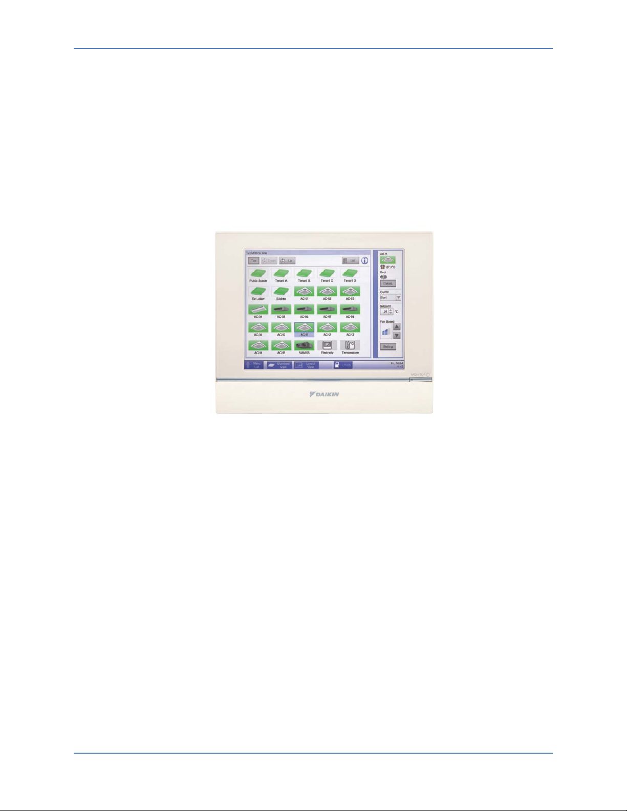
The intelligent Touch Manager (iTM) is now capable of serving as a BACnet® interface for Building
Management System (BMS) integration. The iTM BACnet® Server Gateway option (DCM014A51) will
provide BMS integrators the ability to monitor and control VRV indoor units via the BACnet®/IP protocol.
The iTM BACnet® Server Gateway option eliminates the need for an additional hardware interface for
the BMS to monitor and control a VRV system. The iTM BACnet® Server Gateway option provides
seamless control-logic integration between the iTM and BMS.
Figure 1. iTM BACnet® Server Gateway
1.1 Features:
• Direct connection on iTM using the BACnet®/IP Protocol.
• BACnet® virtual router function implemented:
» Individual BACnet® device ID assigned to each indoor unit group address.
» Indoor unit group names created in the iTM are visible on the BMS.
• Easy commissioning using CSV file.
» Available objects can be configured for each indoor unit.
• Support Change of Value (COV) notifications to BMS.
• Configurable as a BACnet® foreign device if BBMD exists on a different subnet within BACnet® network.
• Independent heating and cooling setpoints for occupied and unoccupied periods.
• Individual min/max Setpoint Range Limitation for heat and cool modes.
• The iTM’s auto-changeover, setpoint range limitation, setback, dual setpoint logic, and schedule can be accessed by the BMS.
The intelligent Touch Manager (hereinafter referred to as "iTM") supports the BACnet® 2004 protocol
(hereinafter referred to as "BACnet® specifications"). The iTM operates as a BACnet® server that
provides BACnet® objects to monitor/operate indoor units connected to the DIII network in response to
requests from a Building Management System (BMS), i.e., BACnet® client.
6 Design Guide DCM014A51
Part 1. Overview
This document describes the operation for the BACnet® Server Gateway option for the iTM.
1.2 BACnet® Compatibility
• Packaging of the VRV indoor unit objects:
» Compatible with BACnet® (ANSI / ASHRAE-135).
» Compatible with BACnet® / IP (ISO16484-5).
• Conforming to Safety and Electromagnetic Compatibility (EMC) rules and regulations.
1.3 System Outline
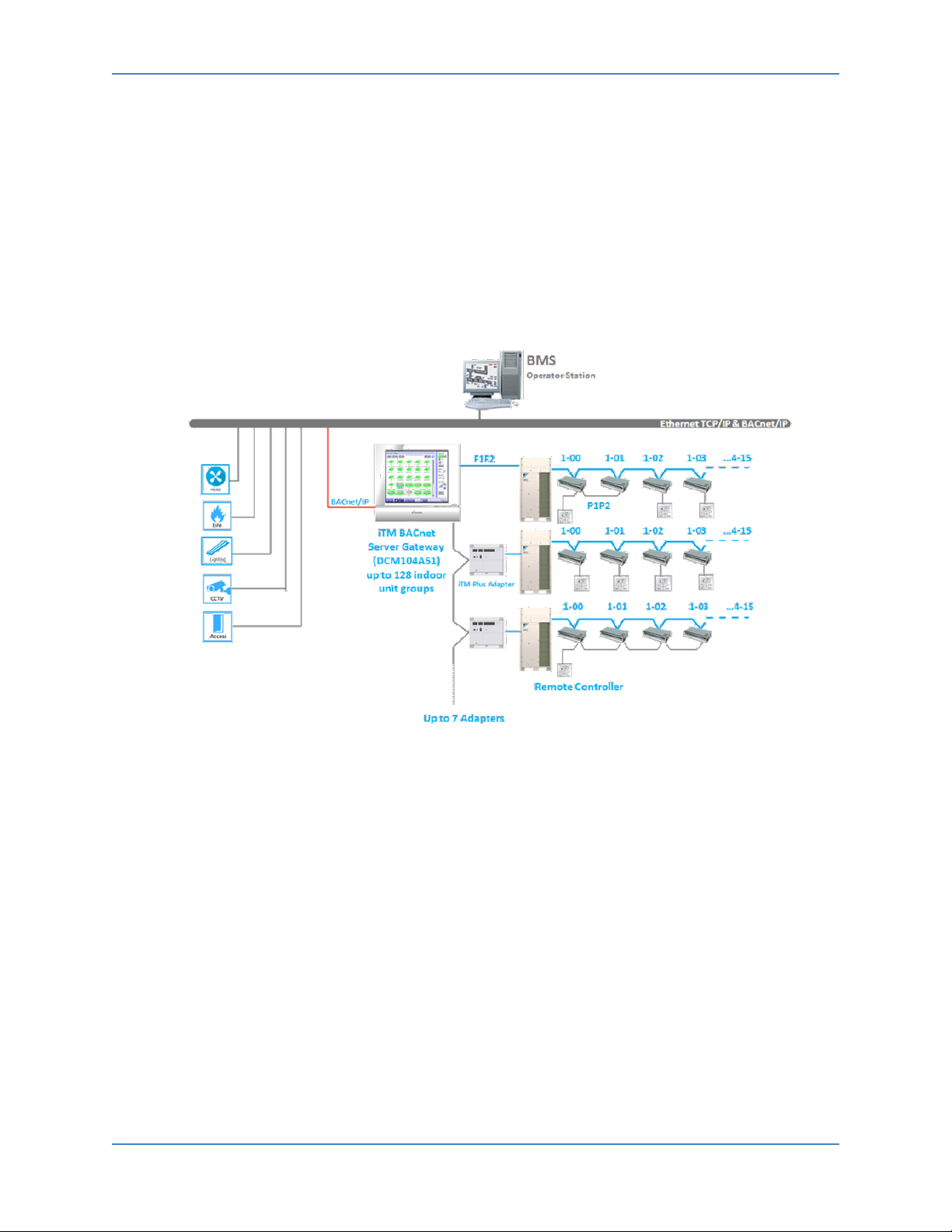
1. Typical BACnet® Server Gateway Application:
Figure 2. Typical Daikin VRV System
2. The iTM BACnet® Server Gateway (DCM014A51) software option provides communication between the VRV system and the BMS. The operation and monitoring of the VRV systems through BACnet® communication uses the BACnet®/IP protocol.
3. Up to 128 indoor unit management points can be controlled and monitored through the iTM BACnet® Server Gateway.
4. Up to 7 additional DIII-Net communication systems can be added with optional iTM Plus Adaptors. The iTM Plus Adaptor is intended for use with the iTM, and shall not be used independently.
DCM014A51 Design Guide 7

Part 1. Overview
2. VRV System Overview
The Daikin VRV system consists of outdoor units, indoor units, zone controllers, centralized controllers,
and BMS interfaces. The customizable Daikin control system is built around the VRV system, and does
not require advanced field engineering (i.e., programming) for the control of the VRV system, except for
field settings configurations. The iTM BACnet® Server Gateway can be used for monitoring, scheduling,
control, and interlock operation. A BMS can be used in conjunction with the Daikin controllers to share
operation workload to reduce project costs.
2.1 Types of Daikin VRV Systems
The VRV system can consist of either a Heat Recovery system, Heat Pump systems, or system that has a combination of both.
1. Heat Recovery systems can provide simultaneous cooling and heating to each indoor unit served by the same outdoor unit with use of Branch Selector Boxes (BS Box).
Figure 3. Heat Recovery System
2. Heat Pump systems only allow each outdoor unit and its connected indoor units to operate in either cooling or heating mode. Multiple Heat Pumps systems can be installed to operate independently in either cooling or heating mode.
Figure 4. Heat Pump System
8 Design Guide DCM014A51
Part 1. Overview
2.2 DIII-Net System and Group Addresses
1. The DIII-Net system consists of the following: a. Up to 10 VRV outdoor units (daisy chained). b. Up to 128 indoor units.
2. The iTM (central controller) and DIII-Net system consists of the following: a. Up to 10 VRV outdoor units (daisy chained). b. Up to 64 indoor unit groups (128 indoor units). c. Up to 7 iTM Plus Adapters can be connected to a single iTM. Each adapter can contain up to
64 group addresses and 10 outdoor units.
3. When a centralized controller is connected to the DIII-Net system, a unique group address must be created for each indoor unit to be monitored and controlled by the central controller.
4. Group Address: a. Indoor units are assigned unique group addresses (up to 64 per DIII-Net system) manually
during the VRV commissioning.
b. Addresses are as follows: 1-00 to 1-15, 2-00 to 2-15, 3-00 to 3-15, 4-00 to 4-15.
c. With the use of the iTM Plus Adapter, up to 8 DIII-Net systems can be connected to a single
iTM. Each DIII-Net system will be assigned a port number with the iTM being port 1. For
example, an indoor unit connected to the iTM will have the complete group address of 1:1-
00. Similarly, each additional system will be assigned a port number 2 to 8 (2:1-00, 3:1-00,
etc.).
2.3 Remote Controller Group and Group Address
1. A remote control group consists of 1 -16 indoor units connected (via P1P2 daisy chain) to the
same remote controller. The indoor unit group allows for a maximum of 2 remote controllers
to be connected to the same remote controller group. It is not required to have a remote
controller connected to an indoor unit. If no remote controllers are used there should be a
centralized method for monitoring and controlling the indoor units.
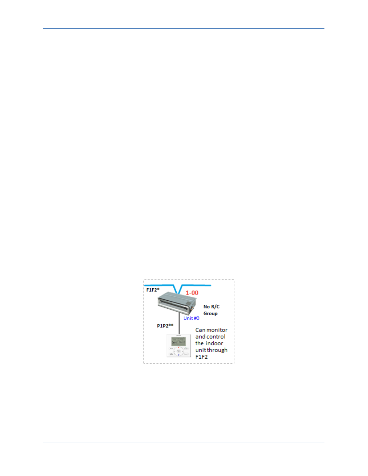
2. Assigning a group address to a single indoor unit (typical configuration):
* F1F2 = DIII-Net ** P1P2 = Remote Controller line
Figure 5. Assigning Group Address to a Single Indoor Unit
DCM014A51 Design Guide 9

Part 1. Overview
3. Assigning one group address to a remote controller group:
Figure 6. Assigning One Group Address to a Remote Controller Group
4. Assigning a group address to each indoor unit in a remote controller group:
Figure 7. Assigning a Group Address to Each Indoor Unit in a Remote Controller Group
Note: As shown in the figures above, a remote controller group consists of several
indoor units wired to the same remote controller. A remote controller group consists of
1-16 indoor units that can be started or stopped simultaneously. For units without a
remote controller, each unit is treated as a group.
10 Design Guide DCM014A51
Part 1. Overview
2.4 Commanding Mode Change for Heat Recovery and Heat Pump Systems
What is a Changeover Master?
1. When the VRV contractor has commissioned a Heat Pump system, an indoor unit can be nominated as the changeover master. This allows the nominated unit to change the mode of operation for all units connected to the same outdoor unit.
Figure 8. Heat Pump System
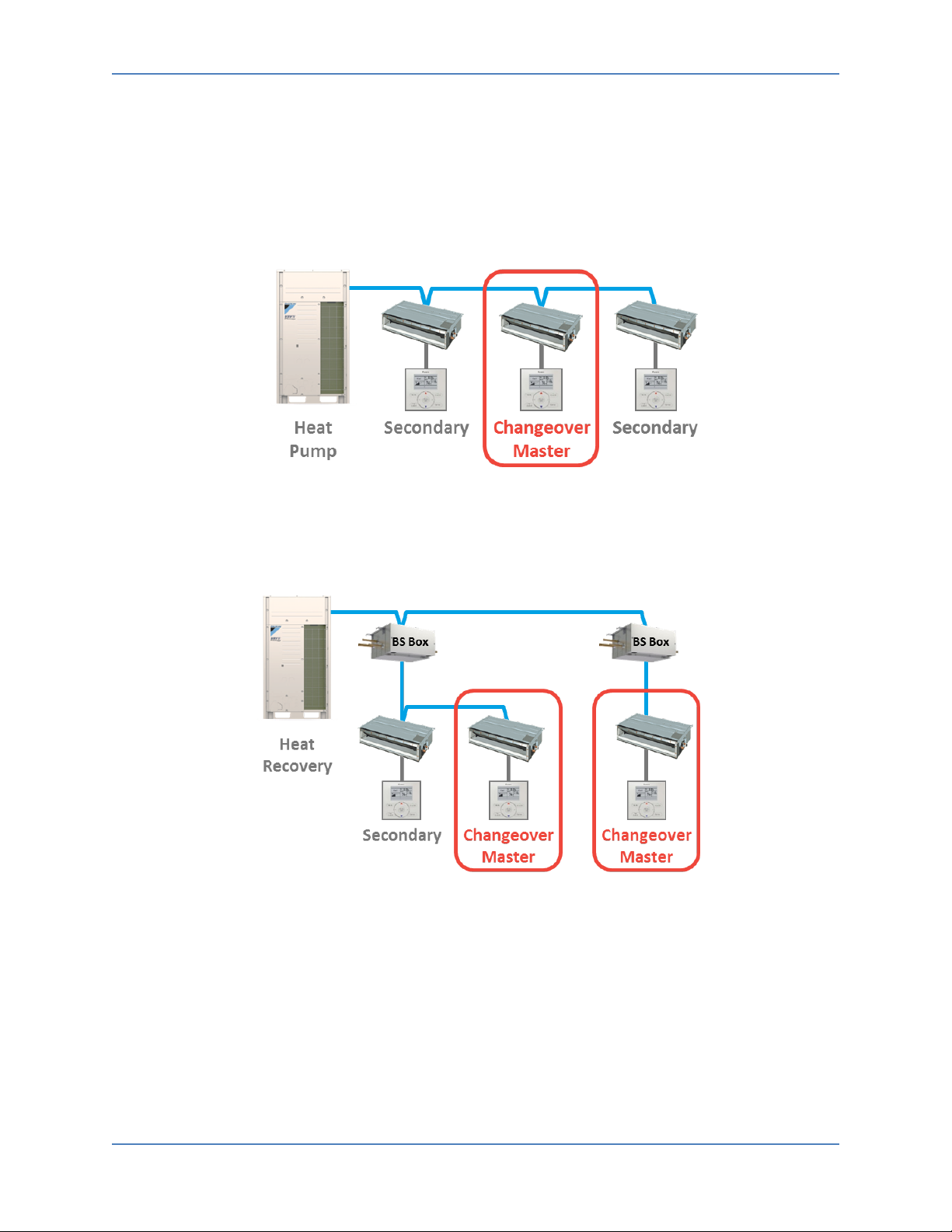
2. A Heat Recovery system can utilize BS Boxes to provide simultaneous heating and cooling for each zone.
Figure 9. Heat Recovery System
3. Every unit or group of units connected to a BS Box port can either be in cooling or heating mode, i.e., units connected to the same BS Box port operate as a mini Heat Pump system.
DCM014A51 Design Guide 11

Part 1. Overview
•
• •
• •
•
• •
•
2.5 Changeover Master and Secondary (Non-Master) Indoor Units
1. Cool and heat modes are only available for selection on the cool/heat changeover master
indoor unit. The following table indicates the available operating modes for secondary indoor
units in the system based on the selected mode of the master indoor unit.
When the master
indoor unit is set to:
Cool Dry Heat Fan
Secondary indoor units in the
system can be set to:
Cool mode
Dry mode
Heat mode
Fan mode
2.6 Indoor Unit Logic
1. The indoor unit contains control logic to maintain room temperature by adjusting the
refrigerant flow and has the following data points:
a. Unit ON/OFF.
b. Operation Mode – Cool, Heat, Fan, Dry, Auto (Auto mode is not recommended as it can
create large temperature differentials between mode changes).
c. Setpoint – 60
o
F to 90oF, 1oF basis (16oC to 32oC, 0.1oC basis).
d. Room Temperature (read only).
e. Fan Speed – L, ML, M, MH, H, Auto (depends on indoor unit type).
f. Airflow Direction (if the indoor unit has louvers).
g. Alarm Status (read only).
h. Malfunction Code (read only).
2. Indoor Unit Sequence of Operation a. During the cooling thermo-on (call for cooling) period, the indoor unit fan will operate based
upon the fan setting from the local controller, iTM, or BMS.
b. During the cooling thermo-off (cooling satisfied) period, the fan will continue to operate
based on the setting from the local controller, iTM, or BMS fan speed setting. However, the
fan can be turned OFF during the thermo-off period with a field setting (depends on the
indoor unit type). Also, the fan should not be OFF when an indoor unit receives outside air.
c. During the heating thermo-on (call for heating) period, the indoor unit fan will operate
based on the fan setting from the local controller, iTM, or BMS.
d. During the heating thermo-off (heating satisfied) period, the fan will continue to operate in
LL (Low Low) speed (default). The fan can be set to ON (H, MH, M, ML, L), LL or completely
OFF with a field setting (depends on the indoor unit type). However, the fan should not be
OFF when an indoor unit receives outside air.
12 Design Guide DCM014A51

Part 1. Overview
3. Dry Mode a. When selected, the setpoint is based on the room temperature as not to over cool.
1. Setpoint = Return Air (when the Return Air ≤ 75°F).
2. Setpoint = Return Air – 1°F (when the Return Air > 76°F).
b. The current setpoint is not displayed on the local controller, iTM, or the BACnet® Server
setpoint present value during Dry mode.
c. In Dry mode (or Fan mode), the BMS can write the cooling and heating setpoints to the iTM,
and are set to the IDU management point in the iTM. However, the cooling and heating
setpoints are not sent to the indoor unit.
4. Room Temperature Sensing a. The room temperature can be measured by the following:
1. Indoor unit return air sensor (depending on indoor unit model).
2. Remote temperature sensor (KRCS01-1B/4B).
3. Sensor in the BRC1E73 (local remote controller). b. The sensing local method depends on the indoor unit configuration (field setting). c. The BMS cannot send the room temperature to the indoor unit due to the fact that the
room temperature is a read only point for the BMS.
DCM014A51 Design Guide 13

Part 1. Overview
3. iTM Overview
3.1 Indoor Unit Management Point
1. The iTM manages the indoor unit groups as an Indoor Unit Management Point only when a group address is assigned (see 2.3 Remote Controller Group and Group Address) to an indoor unit(s).
One (1) indoor unit management point consists of the following on the iTM:
Function Monitor Control
On/Off X X
Operation Mode X X
Occ Cooling/Heating Setpoint X X
Unocc Cool/Heat Setpoint X X
Fan Speed X X
Vane Position X X
Remote Controller Prohibit (On/Off, Mode, Setpoint) X
Room Temperature X
Setpoint Range Limitation (Cool/Heat Min/Max) X
Error Status X
Malfunction Code X
Override Timer X
Setpoint Tracking X
Minimum Setpoint Differential X
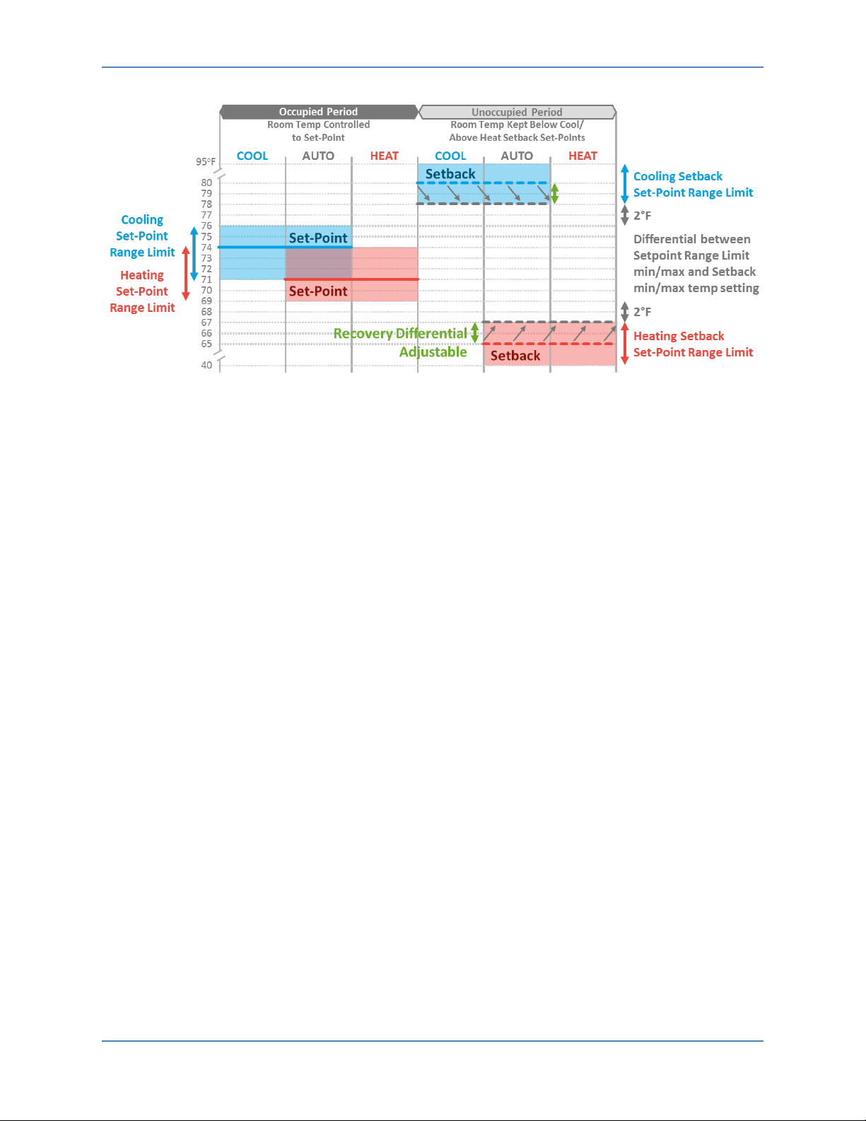
2. Setpoints a. Independent cool and heat dual setpoints in the occupied period. Single setpoint mode is
available with 0
b. Occupied setpoint range for cooling and heating are configurable by Setpoint Range
Limitation within 60
heating setpoint and the heating setpoint cannot be set higher than the cooling setpoint.
c. Minimum Cool/Heat Setpoint Differential refers to the difference between the cooling and
heating setpoint values. The differential can be set between 0
d. Setpoint tracking is used to lock in the Min. Setpoint Differential for cooling and heating to a
fixed value.
e. The setback setpoints (cooling and heating) in the unoccupied period are adjustable
between 50
f. The setback setpoints can only be set outside of the occupied setpoint range with a 2
differential. The setback (unoccupied) setpoint will reduce the occupied setpoint range
automatically to maintain a 2
(heating) possible occupied setpoints.
o
F min setpoint differential and setpoint tracking enabled.
o
F – 90oF as a default. The cooling setpoint cannot be set lower than the
o
F – 7oF.
o
F – 95oF.
o
F fixed differential from the highest (cooling) and lowest
o
F
14 Design Guide DCM014A51
Part 1. Overview
Figure 10. Relationship between Setpoints, Setback, and Setpoint Range Limitation
3. Setback a. The Setback function keeps the room temperature at a moderate level with the setback
setpoints when the indoor unit is off (when the room is unoccupied). The indoor unit only
turns on if the room temperature rises to meet the Cool Setback Setpoint in cooling mode,
or if the room temperature falls to meet the Heat Setback Setpoint in heating mode. Once
the room temperature has recovered and the guard timer has expired, the indoor unit is
turned off.
b. A guard timer keeps the indoor unit on for at least 30 minutes after the Setback function
turns on the indoor unit.
c. If the indoor unit is set to Fan or Dry mode, the setback function will not work.
d. The iTM setback provides independent setback setpoints for cooling and heating.
e. By default the setback setpoints are disabled and can be enabled by the schedule, interlock,
and setting features.
1. The default setback setpoint for cooling is 80
2. The default setback setpoint for heating is 64
3. Independent Setback Recovery Temp (hysteresis) for cooling (-4
o
(+4
F default). Configurable from 2oF to 10oF.
o
F (configurable).
o
F (configurable).
o
F default) and heating
f. Setback Control Logic
1. Room temperature and setback setpoint are evaluated every five minutes for each indoor unit.
2. If the indoor unit is turned on by the iTM manually (or by the Schedule function), the normal operation is maintained, i.e., the indoor unit maintains the room temperature from the setpoint.
3. When the Setback function turns on the indoor unit (unless it is turned off by the iTM manually, by the Schedule function, or by a remote controller), the Setback function maintains the room temperature below (or above) the setback setpoint.
DCM014A51 Design Guide 15
Part 1. Overview
4. Timer Extension a. The Timer Extension is used to turn the indoor unit off (after a specified time has expired)
when it is turned on manually by the iTM or remote controller during unoccupied hours. It
can be set for 30, 60, 90, 120 (default), 150, or 180 minutes. The Timer Extension must be
enabled to operate during the unoccupied period.
b. Timer Extension function will not turn off an indoor unit that was turned on by the Setback
function.
3.2 Automatic Control
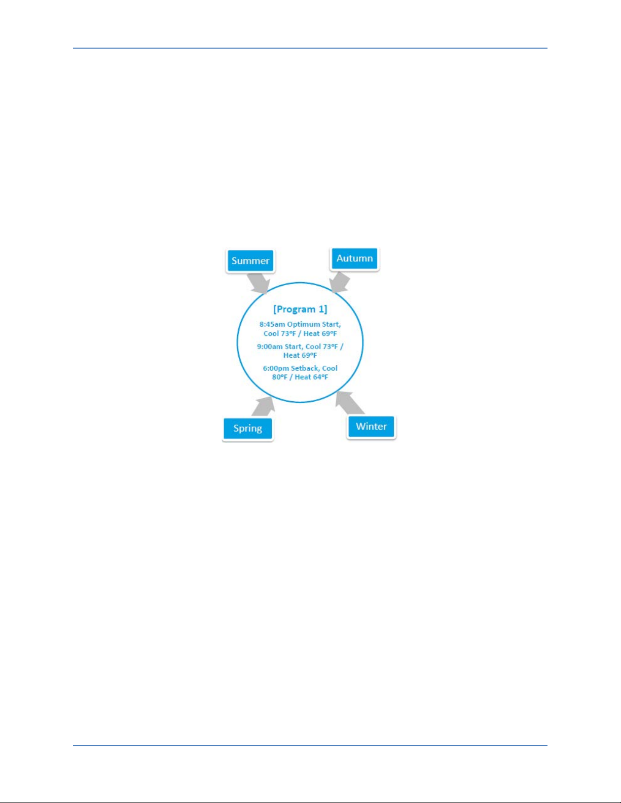
1. Scheduling a. Independent cool and heat setpoints and independent setback setpoints allow for one
schedule to be set to run year round.
Figure 11. Year round setpoint schedule
b. Up to 100 schedule programs can be created.
c. A 7 day, 5+2 (Weekday + Weekend), 5+1+1 (Weekday + Saturday + Sunday) and 1 (Everyday)
schedules can be created in the iTM.
d. Up to 20 events can be registered each day.
e. Special Day (such as holiday) events can be created:
1. Up to 5 special day patterns can be registered.
2. Up to 20 events can be registered each day.
3. Events can be set by calendar date or by week and day of the month (Ex. July 4
th
or 1st
Monday in September).
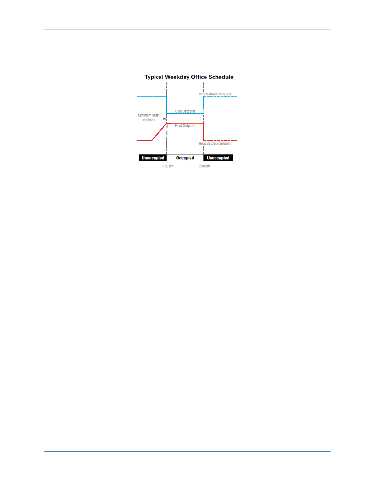
f. The iTM schedule can provide an Optimum Start function to insure the room temperature
achieves setpoint at the scheduled event time. Optimum Start calculates the time when the
target indoor units turn on, according to the room temperature and the setpoint for the
current operation mode. Optimum Start evaluates and adjusts the turn-on time
appropriately. The schedule and Optimum Start feature can only be set via the iTM schedule
function and cannot be configured by the BMS.
16 Design Guide DCM014A51
Part 1. Overview
g. The Daylight Savings Time (DST) setting automatically adjusts the iTM clock to insure
scheduled operation times are met.
Figure 12. Typical Weekday Office Schedule
2. iTM Auto-Changeover a. Using the advanced auto-changeover functions in the iTM, the BMS programming time is
significantly reduced. Automatic changeover is available for both Heat Pump and Heat
Recovery systems. The changeover is automatically controlled to occur in the following two
cases:
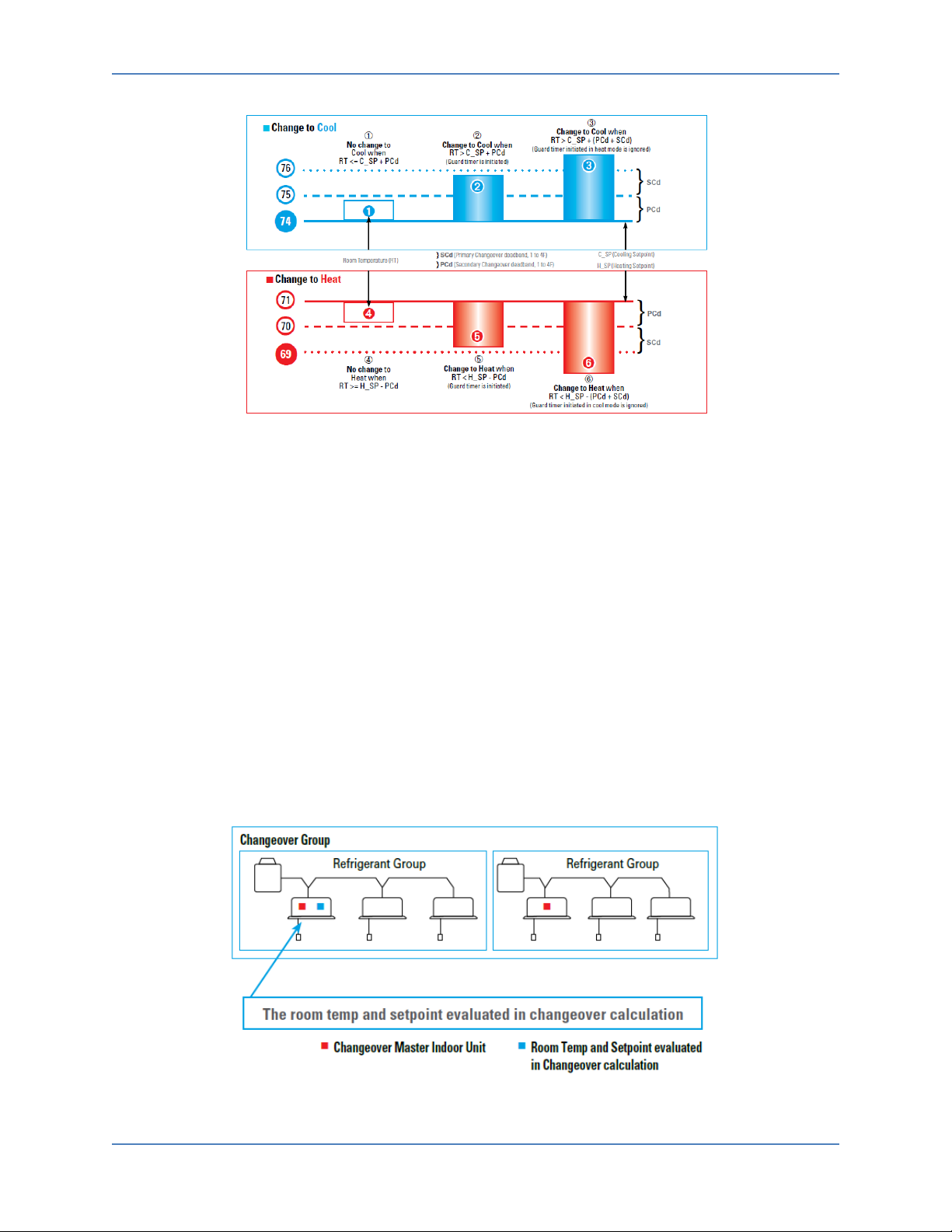
Case 1: Changeover at the primary changeover temperature after the guard timer expires.
1. The changeover is evaluated by how much the room temperature has deviated from the
cooling or heating setpoint. For example, when the room temperature exceeds the
primary changeover deadband from the cooling setpoint, iTM initiates a change from
heating mode to cooling mode.
2. By default, the primary changeover setpoint is 1°F above the cooling setpoint or 1°F
below heating setpoint, which are configurable between 1°F – 4°F.
3. The guard timer can be set to 15, 30, or 60 (default) minutes. a. The initiation of the guard timer is built in to help prevent frequent changeovers
which may cause energy loss.
b. When the setpoint is changed manually or by the schedule, the guard timer is not
active.
DCM014A51 Design Guide 17
Part 1. Overview
Case 2: Changeover at the secondary changeover temperature.
1. By default, the secondary changeover temperature is 1°F above the primary changeover
2. Case 2 will happen while the guard time is active in Case 1.
3. The iTM auto-changeover is applicable to both Heat Pump and Heat Recovery systems.
Figure 13. Cool/Heat Changeover Logic
temperature for cooling, or 1°F below the primary changeover temperature for heating,
which is configurable between 1°F – 4°F.
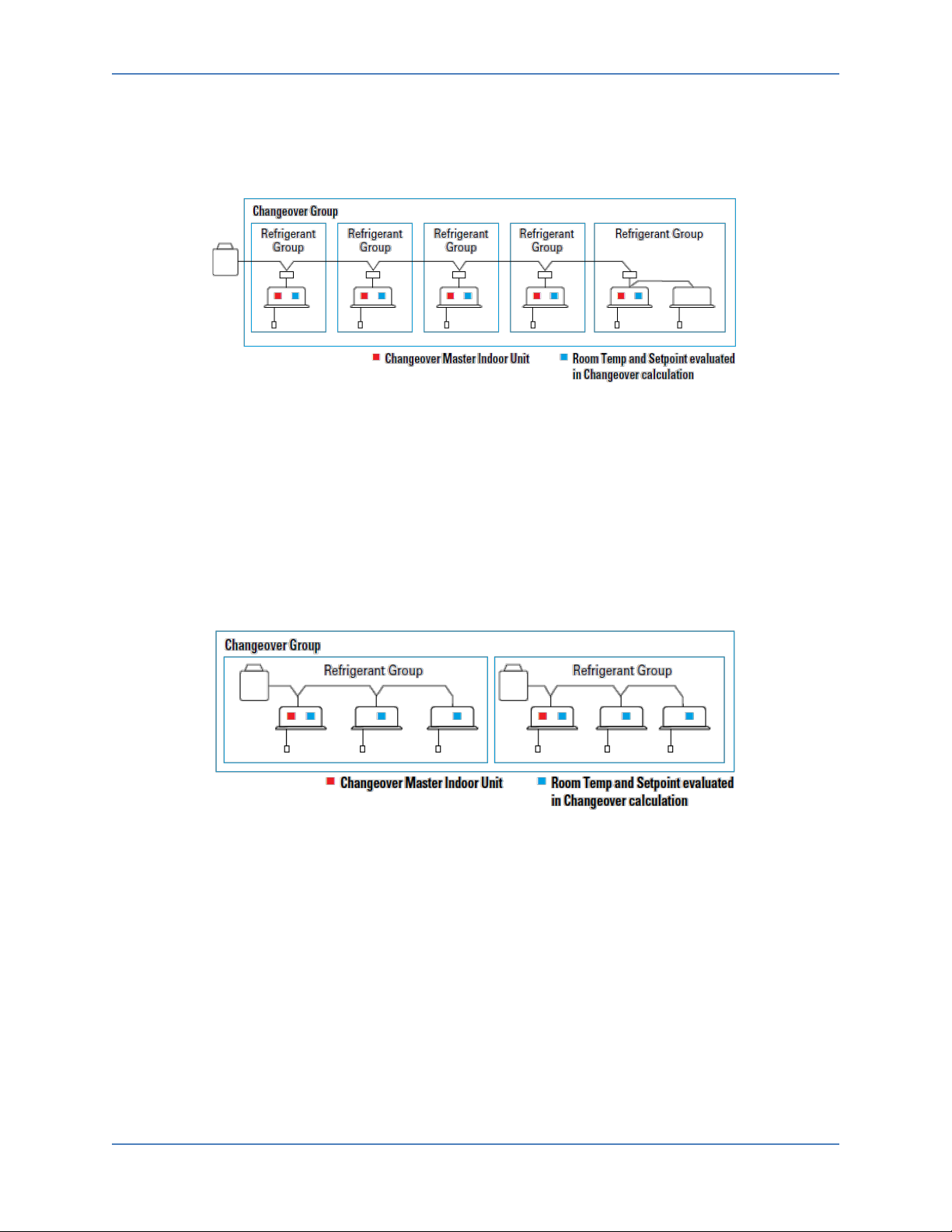
a. The iTM provides four changeover methods to meet a variety of expectations in a
project. Fixed, Individual, Average, or Vote methods can be specified in the
changeover group with targeted indoor units, as well as Primary/Secondary
Changeover deadbands.
1. Fixed Method: a. Changeover is evaluated with the representative indoor unit. b. Changeover affects all indoor units. c. Good method for prioritizing the representative indoor unit for the Heat Pump
system (or multiple units on the same port of the BS Box in Heat Recovery
system).
Figure 14. Fixed Method
18 Design Guide DCM014A51
Part 1. Overview
2. Individual Method: a. Changeover is evaluated by, and affects, each indoor unit individually. b. Used in application with the Heat Recovery system.
Figure 15. Individual Method
3. Average Method: a. Changeover is evaluated based on the average of the room temperature and
average setpoints in the changeover group.
b. A weight (0-3) can be added to each indoor unit demand in the changeover
group. The default is 1.
c. Changeover affects all indoor units in the changeover group.
d. Used in applications with Heat Pump systems (or multiple units on the same
port of the BS Box in the Heat Recovery system).
Figure 16. Average Method
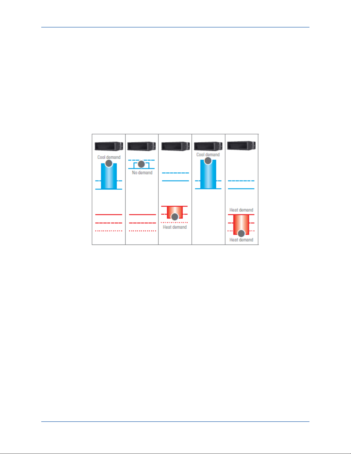
4. Vote Method: a. Changeover is evaluated based on the total cooling demand and total heating
demand. If the total cooling demand is greater than the heating demand, the
iTM changes the indoor units in the changeover group to cool mode.
b. When the changeover group is in cooling mode, the total cooling demand will
decrease; at that point, the total heating demand may become greater than the
cooling demand and change the mode to heating (a guard timer applies).
DCM014A51 Design Guide 19
Part 1. Overview
c. The setpoints can be different in each indoor unit within the changeover group.
The demand is calculated based on the setpoints in comparison to room
temperature for each indoor unit. The demand within the Primary Changeover
deadband (PCd) is considered as no demand.
d. A good method for Heat Pump systems (or multiple units on the same port of
the BS Box in Heat Recovery system) as a pseudo-simultaneous cooling and
heating operation.
e. A weight (0-3) can be added to each indoor unit demand in the changeover
group. The default is 1.
f. An option for heating override can be applied if there is an indoor unit which
the heating demand exceeds [H_SP- (PCd + SCd)].
Figure 17. Vote Method
20 Design Guide DCM014A51
Part 2. Functional Specifications
Part 2. Functional Specifications
1. Introduction
The Daikin iTM BACnet® Server Gateway operates as a BACnet® interpreter using the services defined by
BACnet® to return the status of the indoor units connected to the DIII network. It also sends
configuration commands to the indoor units, in response to requests from the BMS (i.e., BACnet® Client)
which supports the BACnet® protocol (ISO16484-5, ANSI/ASHRAE135).
2. Network Topology
2.1 Visualization of Each Device on the BACnet® Network
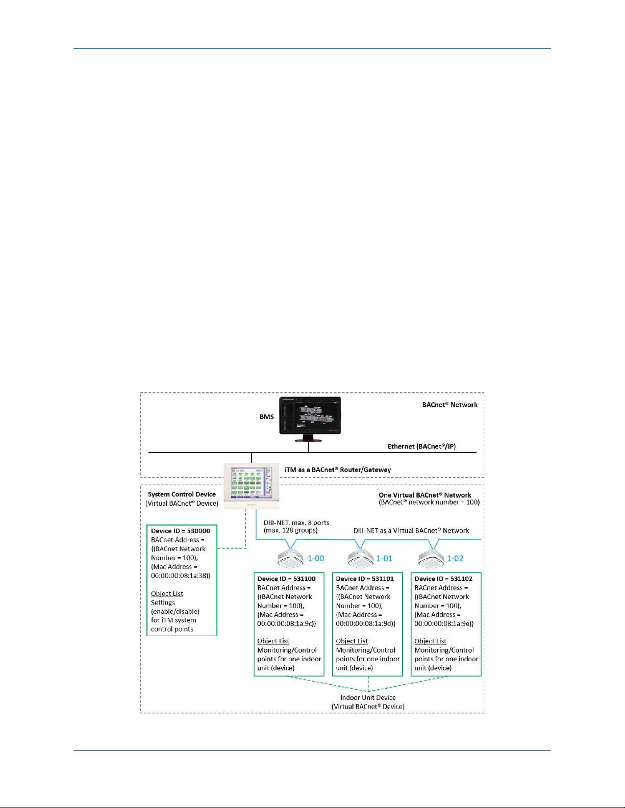
1. iTM: Operates as a BACnet® router/gateway for the VRV indoor units.
2. Indoor unit device: One indoor unit management point is handled as one virtual BACnet®
device.
a. In the BACnet® specifications, the VRV communication line (DIII network) is handled as one
virtual BACnet® network.
(See Annex H.1 and H.2 in the BACnet® 2004 specifications.)
3. System control device: It is handled as a virtual BACnet® device to receive settings (i.e., enable/disable and the like) for the iTM system configuration points.
4. For a typical BACnet® network configuration, see chapters 4.2 and Annex J in the BACnet® 2004 specifications.
Figure 18. BACnet® Network
DCM014A51 Design Guide 21

Part 2. Functional Specifications
4bytes
2bytes
2.2 BACnet® Network Number
1. A BACnet® Client access the virtual BACnet® device of an indoor unit by specifying the BACnet® network number mapped to the virtual BACnet® network.
2. BACnet® network numbers are settable in the range defined in the BACnet® specifications (1 to
65534) default is 100.
2.3 Device ID (Device Instance Number)
1. The Device ID must be a unique number per indoor unit and on the BACnet® network. The setting range is 0 to 4194303.
2. The following Device ID calculation is recommended to be used as the default for each indoor
unit unless otherwise specified by the BMS integrator. The default Device ID should follow the
structure 53XXXX.
a. For the Device ID 531100:
1. 531100 → 53 represents Daikin’s BACnet® vendor ID.
2. 531100 → 1 represents the port number (1 = iTM, 2 – 8 = iTM Plus Adapter address).
3. 531100 → 100 represents the DIII-Net group address 1-00.
2.4 What is a MAC Address?
1. The MAC address is a unique physical address to identify a network device.
2. Each physical medium in a network has a MAC address whose length varies depending on the physical medium.
3. MAC addresses used for physical media are defined by the BACnet® specifications; see chapters 7 to 11 in the BACnet® 2004 specifications.
4. Furthermore, when using BACnet® IP, everything below the IP layer is considered the physical layer by definition so as to handle the 6 bytes composed of the IP address + UDP port number as the MAC address.
(See paragraph J.1.2 in the BACnet® 2004 specifications). Note that the MAC address of a virtual BACnet® device is expressed as described above.
5. In the BACnet® specifications, the address of the data source and destination are specified using the BACnet® network number and this MAC address.
For details, see paragraph 6.2.2.2 in the BACnet® 2004 specifications.
2.5 MAC Address of a Virtual BACnet® Device
1. The MAC address is a 6-byte long expression composed of the device instance number for the
indoor unit and system control device, as indicated below: The MAC address of each device is
represented by the hexadecimal conversion of the device Instance number.
(Ex. Device instance number = 531100 → 00:00:00:08:1a:9c = MAC Address)
Device Instance Number Not used (zero)
2. Settings related to the BACnet® Server Gateway functions such as the device instance number
can be done from the BACnet® Server Gateway configuration in the iTM Service Settings menu.
Refer to the iTM BACnet® Server Gateway Commissioning manual for more details.
22 Design Guide DCM014A51

Part 2. Functional Specifications
3. iTM and BACnet® Server Gateway Logic
3.1 BACnet® Virtual Router Function
1. The iTM BACnet® Server Gateway provides seamless control logic between the iTM and BMS.
2. The BACnet® virtual router function allows the BMS to see each Indoor Unit Management Point as a separate device. This allows for each Indoor Unit Management Point to have its own independent device ID.
3.2 iTM BACnet® Server Gateway Point Logic in the iTM
1. Each point exposed to the BMS from the iTM BACnet® Server Gateway is linked to the logic in
the iTM. This alleviates the need for the BMS integrator to create programming to control the
VRV system. The image below identifies which BACnet® points are linked to the iTM logic.
Figure 19. BACnet® Server Gateway Points
2. Each Indoor Unit Management Point can be assigned independent cooling and heating
occupied and unoccupied setpoints.
a. Setpoints set by the BMS are also updated in the iTM, and setpoints set at the iTM are
updated to the BMS.
b. The same logic applies to the setpoint range limitation as stated in Part 1., 3.1(2)(b) for the
minimum and maximum setpoint for cooling and heating.
c. To see how the occupancy mode is monitored and controlled, refer to 7.2.1.
3. Auto-changeover a. The iTM handles the cool/heat auto-changeover for the Changeover Group that consists of
all indoor units in Heat Pump systems, or under BS units in Heat Recovery system.
b. The Changeover Group is configured in the iTM.
c. The changeover method is configured from one of the following: Fixed, Average, Individual
and Vote which is selected in the iTM.
d. Different changeover options can be selected for each Changeover Group.
e. The Auto-changeover point (system point) allows the BMS to enable or disable all the
Changeover Groups simultaneously when the Changeover Groups are configured in the iTM.
DCM014A51 Design Guide 23

Part 2. Functional Specifications
bit: 31
22 21
0
f. The BMS Integrator should be provided with the Changeover Group configuration.
4. Scheduling a. The iTM can accommodate daily scheduling of the indoor unit groups. b. There are four types of schedules that can be set in the iTM 7 day, Weekday/Weekend,
Weekday/Saturday/Sunday, and Everyday.
c. The BMS can use the “Enable iTM Schedule” point to enable or disable the schedule in the
iTM. Typically the BMS Master Schedule is used to control the indoor units, and iTM
Schedule is not used.
5. Forced System Shutdown a. The “Forced System Shutdown” point can be used to turn off all indoor unit groups
connected to the iTM via the DIII-Net communication bus when an emergency signal has
been received by the BMS. Emergency Stop program should be configured and enabled in
advance.
b. Indoor unit groups cannot be restarted from the remote controller until the Forces System
Shutdown point is set to inactive.
4. VRV System Monitor/Control Objects
4.1 Member Objects
1. In BACnet®, a BACnet Object Identifier (hereinafter abbreviated as "ObjectID") is defined as follows:
BACnet Object Type Instance Number
4.2 Indoor Unit Device
1. Each indoor unit monitoring/control item (called Member Object) is mapped to a BACnet® object (called indoor unit object) and to an ObjectID instance number, as indicated in the following table.
2. Each of the object types BI, BV, MI, MO, and MV sets the text shown in the following table in the Description Property in accordance with the value of the Present_Value.
3. The BMS cannot command an indoor unit from cool to heat (or from heat to cool) if the indoor unit is not designated as the changeover master.
4. When more than one indoor unit is connected to a single remote controller group, the BMS
should only send commands to the indoor unit that is designated to receive the command for
the remote controller group (unit #0). The BMS should not send commands to other indoor
units in the remote control group. If commands are sent to the other indoor units in the
remote controller group, the indoor unit that receives the command will decide if it should
follow the command.
5. During the iTM BACnet® Server Gateway commissioning, the BACnet® objects can be enabled and disabled. If an object is disabled, the object will not be available to be controlled and/or monitored by the BMS.
24 Design Guide DCM014A51

Part 2. Functional Specifications
Instance
Inactive
Active
Text-1
Text-2
Text-3
Text-4
Text-5
Text-6
Text-7
Text-8
1
Occupancy Mode
MO
Unocc
Occ
Standby
Unit On_Off
Status
Sets error
Description
property.
See (1)
below.
Room
Temperature
Occ Cooling
Setpoint
Occ Heating
Setpoint
Unocc Cooling
Setpoint
Unocc Heating
Setpoint
Max Cooling
Setpoint
Min Cooling
Setpoint
Max Heating
Setpoint
Min Heating
Setpoint
Min Setpoint
Heating)
Cooling &
Tracking Mode
16
Fan Speed
MV
Low
Reserved
Medium
Reserved
High
Reserved
Reserved
Auto
17
Airflow Direction
MV
P0
P1
P2
P3
P4
Reserved
Reserved
P7
Timed Override
Operation
Current Unit
Operation
6. Indoor unit points list
No.
10
11
12
13
Object_Name Type
2
3 Alarm Status BI Normal Alarm
4 Operation Mode MV Cool Heat Fan Dry
5
6
7
8
9
BI Off On
AI
AV
AV
AV
AV
AV
AV
AV
AV
Remarks
code in the
*1, *2
*1, *2
*1, *2
*1, *2, *3
*1, *2, *3
*1, *2, *4
*1, *2, *4
Differential
14
(Cooling &
15
Heating Setpoint
18
19
AV
BV Disable Enable
BV Disable Enable
MI Off Normal Override Setback
*1, *2
Continued on next page.
DCM014A51 Design Guide 25

Part 2. Functional Specifications
Inactive
Active
Text-1
Text-2
Text-3
Text-4
Text-5
Text-6
Text-7
Text-8
Remote Controller
(On_Off)
Remote Controller
(Operation Mode)
Remote Controller
(Setpoint)
23
Filter Sign Status
BI
Normal
Alarm 24
Filter Sign Reset
BV
Reset
Alarm 25
Indoor Fan Status
BI
Off
On
Communication
Status
27
Thermo-on Status
BI
Off
On
Defrost/
Hot Start
29
Aux Heater Status
BI
Off
On 30
Forced Thermo-off
BV
Disable
Enable
Indoor Unit
Changeover Option
Not
Available
Instance
No.
20
21
22
26
28 Compressor Status MI Off On
31
Object_Name Type
Prohibit
Prohibit
Prohibit
MV Permit Prohibit Stop Only
BV Permit Prohibit
BV Permit Prohibit
BI Normal Alarm
BI
Remarks
Available
*1: The unit of temperature (Celsius or Fahrenheit) follows the iTM locale (regional settings).
*2: The number of valid digits for each object is shown in the table below.
If a value entered from BMS has a higher precision than the number of significant digits of an
object, the digits after the significant digits are rounded.
(For example, when Occ Cooling Setpoint is "75.55" in degrees Fahrenheit, round it to "76".)
Regarding values in commands sent from the BMS, the iTM rounds them off to the number of the
significant digits.
(For example, if the value in a command for Occ Cooling Setpoint is "75.55" in degrees Fahrenheit,
it is rounded to "76".)
Object Name
“Room Temperature” One decimal place One decimal place
"Occ Cooling Setpoint" "Occ Heating Setpoint"
"Unocc Cooling Setpoint" "Unocc Heating Setpoint"
"Max Cooling Setpoint" "Min Cooling Setpoint"
"Max Heating Setpoint" "Min Heating Setpoint"
"Min Setpoint Differential (Cooling & Heating)” Integer Integer
One decimal place Integer
Number of valid digits
Celsius Fahrenheit
*3: When the Out_Of_Service property is TRUE, the setting items (Setback Temperature (Cool/Heat),
Min Setpoint Differential (Cooling & Heating) that are mapped to the object are disabled.
Therefore, a value set on the indoor unit management point remains unchanged even if
Present_Value is changed.
26 Design Guide DCM014A51

Part 2. Functional Specifications
*4: The Out_Of_Service property of "Max Cooling Setpoint" and "Min Cooling Setpoint" indicates the
upper and lower limit of the Cool Setpoint change along with the Present_Value.
(When the Out_Of_Service property of either object is changed from FALSE → TRUE, the
Out_Of_Service property of the other object also changes from FALSE → TRUE.)
The "Max Heating Setpoint" and "Min Heating Setpoint" which indicates the upper and lower limit
of the Heat Setpoint also behaves in the same way.
When the Out_Of_Service property is TRUE, the setting items (Max and Min Setpoint) mapped to
an object are disabled, so a value set for the indoor unit management point remains unchanged
even when the Present_Value changes.
4.3 System Control Device
1. The instance numbers of the Object IDs are mapped to the system control settings on the iTM as shown in the table below.
2. Each of the BO and MV object types set the text shown in the table below for the Description Property in accordance with the value of Present_Value.
Instance
No.
1
2
3
4 System Forced Off BO Inactive Active
Object_Name Type
Enable iTM Schedule
Operation
Enable iTM
Auto-Changeover
Operation
Timed Override
Minutes
Inactive Active
Text-1 Text-2 Text-3 Text-4 Text-5 Text-6 Text-7
BO Disable Enable
BO Disable Enable
MV 30 60 90 120 150 180
4.4 Restrictions
1. When a Present Value (PV) is set by the BMS, the BACnet® Server in iTM updates the PV and keeps the previous PV.
2. The BACnet® Server in iTM sends the new PV to Management Point in iTM. The BACnet® Server in iTM then starts a 10 minute timer.
3. If the value in Management Point is changed (i.e., the indoor unit accepted the new value and
sent back the new status to iTM), the Management Point in iTM sends the new value to the
BACnet® Server in iTM. The BACnet® Server in iTM updates the PV and resets the 10 minute
timer.
4. If the value in Management Point is not changed (i.e., the indoor unit did not accept the new value and did not update the status to iTM) nothing happens. When the 10 minute timer expires, the BACnet® Server in iTM resets to the previous PV.
Remarks
DCM014A51 Design Guide 27

Part 2. Functional Specifications
•
• Cool SP range: 70-76°F
•
• Cool SP range: 70-76°F
• Sets Cool SP max
85°F
• PV: 85°F, previous PV: 76°F
Start 10-min timer
•
• Cool SP range: 70-78°F (Changed)
• PV 78°F
• Reset 10-min timer
•
85°F again
• PV: 85°F, previous PV: 78°F
Start 10-min timer
•
• Cool SP range: 70-78°F (No change)
• When 10-min timer expires, PV
back to 78°F
Step
BMS
BACnet® Server in iTM
Management Point in iTM
• Cool SP range: 70-78°F
• Cool SP: 72°F
• Cool SP range: 70-78°F
• Cool SP: 72°F
• PV: 68°F, previous PV: 72°F
• Start 10-min timer
• Cool SP 68°F is rounded to 70°F due to
Cool SP: 70°F (Changed)
•
• Reset 10-min timer
• Sets Cool SP 68°F
again
• PV: 68°F, previous PV: 70°F
Start 10-min timer
•
• Cool SP: 70°F (No change)
• When 10-min timer expires, PV
back to 70°F
EXAMPLE 1 – Cool SP Max
Step BMS BACnet® Server in iTM Management Point in iTM
Pre-condition
Unocc Cool SP: 80°F
Cool Setback SP: 80°F
#1
#2
#3
#1
#2
#4
Sets Cool SP max
EXAMPLE 2 – Cool SP
Pre-condition
#1
#2
#3
• Sets Cool SP 68°F
•
• Sends 85°F to Management Point
•
• Sends 85°F to Management Point
• Sends 68°F to Management Point
PV 70°F
Cool SP max 85°F is rounded to 78°F
due to Cool Setback SP 80°F.
• Updates 78°F to the BACnet® Server
Cool SP max 85°F is rounded to 78°F
due to Cool Setback SP 80°F
Cool SP range 70-78°F
•
• Sends 70°F to BACnet® Server
#1
#2
#4
•
• Sends 68°F to Management Point
Cool SP 68°F is rounded to 70°F due to
the Cool SP range 70-78°F
28 Design Guide DCM014A51

Part 2. Functional Specifications
Step
BMS
BACnet® Server in iTM
Management Point in iTM
Indoor Unit
•
Cool
•
mode Fan
•
mode Fan
• Operation mode: Fan
Server
• Sets
mode Heat
• Cannot accept Heat
slave unit
• Periodical status
Operation mode Fan
• When 10-min timer
expires, PV back to Fan
EXAMPLE 3 – Operation Mode to Changeover Slave Unit
Pre-condition
#1
#2
#3
#1
#2
#4
Sets
Operation
Operation
• Operation mode: Cool • Operation mode: Cool
• PV: Fan, previous PV: Cool
• Start 10-min timer
• Sends Fan mode to
Management Point
• PV Fan
• Reset 10-min timer
• PV: Heat, previous PV: Fan
• Start 10-min timer
• Sends Heat to
Management Point
• Send Fan mode to Indoor
Unit
(Changed)
• Send Fan to BACnet®
• Send Heat to Indoor Unit
• Operation mode: Fan (No
change)
Operation mode:
Accepts Fan mode
• Status update to
iTM as Operation
due to changeover
report to iTM as
DCM014A51 Design Guide 29

Part 2. Functional Specifications
Support
□ = No
Configurable with
Gateway Configuration
Object_Name
CharacterString
R ■ R
Indoor unit name*
Object_Type
BACnetObjectType
R ■ R
DEVICE
System_Status
BACnetDeviceStatus
R ■ R
Fixed to OPERATIONAL
Vendor_Name
CharacterString
R ■ R
DAIKIN Industries LTD
Vendor_Identifier
Unsigned16
R ■ R
Fixed to 53 (= DAIKIN)
Model_Name
CharacterString
R ■ R
Fixed to "Indoor Unit"
Firmware_Revision
CharacterString
R ■ R
Application_Software_
Version
Location
CharacterString
O
□
Port No. + Group
Ex: "1:1-00"
Protocol_Revision
Unsigned
R ■ R
RP, RPM, WP, WPM, I-
SubCOV
Protocol_Object_
Types_Supported
BACnetObjectTypesSupp
orted
AI, AV, BI, BV, MI, MO,
MV, Device
BACnetARRAY[N] of
BACnetObjectIdentifier
Max_APDU_Length_
Accepted
Segmentation_
Supported
Max_Segments_
Accepted
VT_Class_Supported
List of BACnetVTClass
O1
□
Active_VT_Sessions
List of BACnetVTSession
O2
□
Local_Time
Time
O3,4 ■ R
Follows the iTM clock
Local_Date
Date
O3,4 ■ R
Follows the iTM clock
UTC_Offset
Signed
O4 ■ R
Follows the iTM clock
Daylight_Saving_Status
Boolean
O4 ■ R
Follows the iTM clock
* The character code for indoor unit names is UTF-8
5. Properties
5.1 Device Object Type
1. Indoor Unit Device
Property Identifier Property Datatype
Object_Identifier BACnetObjectIdentifier R ■ R
CharacterString R ■ R
Description CharacterString O ■ R
Protocol_Services_
Supported
BACnetServiceSupported R
Compatible
Class
■ = Yes
■ R
R: Readable
W: Writable
-
Remarks
BACnet® Server/
Address connected to
DIII-NET
Am, I-Have, TimeSync,
Who-Is, Who-Has,
UTCTimeSync,
Object_List
R ■ R
R ■ R
Unsigned R ■ R 1024
BACnetSegmentation R ■ R SEGMENTED_BOTH
Unsigned O1 ■ R Fixed to 100
-
-
30 Design Guide DCM014A51
 Loading...