

Daikin DCH090, DCC060, DCH060, DCH072, DCH102 Service Instructions Manual
...
Ser vice Instr uctions
DCC Cooling/DCH Heat Pumps
Commercial Package Units
with R-410A Refrigerant
4 - 6 Tons & Accessories
Not for installation in the United S tates or Canada. This unit is for export only.
This manual is to be used by qualified, professionally trained HVAC
technicians only. Daikin does not assume any responsibility for property
damage or personal injury due to improper service procedures or services
performed by an unqualified person.
Copyright © 2015 - 2016
RSDX6412006r1
November 2016
T ABLE OF CONTENTS
IMPORTANT INFORMATION .................................2 - 3
PRODUCTION IDENTIFICATION ..........................4 - 6
PRODUCT DESIGN .............................................7 - 10
SYSTEM OPERATION.......................................11 - 16
SCHEDULED MAINTENANCE ................................. 17
TROUBLESHOOTING CHARTS ................................ 18
SERVICING TABLE OF CONTENTS ........................ 19
SERVICING .......................................................20 - 39
UNIT WIRING DIAGRAMS ....................................... 40
IMPORTANT INFORMATION
Pride and workmanship go into every product to provide our customers with quality products. It is possible, however,
that during its lifetime a product may require service. Products should be serviced only by a qualified service
technician who is familiar with the safety procedures required in the repair and who is equipped with the proper tools,
parts, testing instruments and the appropriate service manual. REVIEW ALL SERVICE INFORMATION IN THE
APPROPRIATE SERVICE MANUAL BEFORE BEGINNING REPAIRS.
IMPORTANT NOTICES FOR CONSUMERS AND SERVICERS
RECOGNIZE SAFETY SYMBOLS, WORDS AND LABELS
O
NLY PERSONNEL THAT HAVE BEEN TRAINED TO INSTALL
ADJUST, SERVICE OR REPAIR (HEREINAFTER
EQUIPMENT SPECIFIED IN THIS MANUAL SHOULD SERVICE THE
EQUIPMENT
FOR ANY INJURY OR PROPERTY DAMAGE ARISING FROM
IMPROPER SERVICE OR SERVICE PROCEDURES
THIS UNIT, YOU ASSUME RESPONSIBILITY FOR ANY INJURY OR
PROPERTY DAMAGE WHICH MAY RESULT
JURISDICTIONS THAT REQUIRE ONE OR MORE LICENSES TO
SERVICE THE EQUIPMENT SPECIFIED IN THIS MANUAL, ONLY
LICENSED PERSONNEL SHOULD SERVICE THE EQUIPMENT
MPROPER INSTALLATION, ADJUSTMENT, SERVICING OR REPAIR
I
OF THE EQUIPMENT SPECIFIED IN THIS MANUAL, OR ATTEMPTING
TO INSTALL, ADJUST, SERVICE OR REPAIR THE EQUIPMENT
SPECIFIED IN THIS MANUAL WITHOUT PROPER TRAINING MAY
RESULT IN PRODUCT DAMAGE, PROPERTY DAMAGE, PERSONAL
INJURY OR DEATH
. THE
MANUFACTURER WILL NOT BE RESPONSIBLE
.
, “
. IN
ADDITION, IN
SERVICE
. IF
,
”)
THE
YOU SERVICE
.
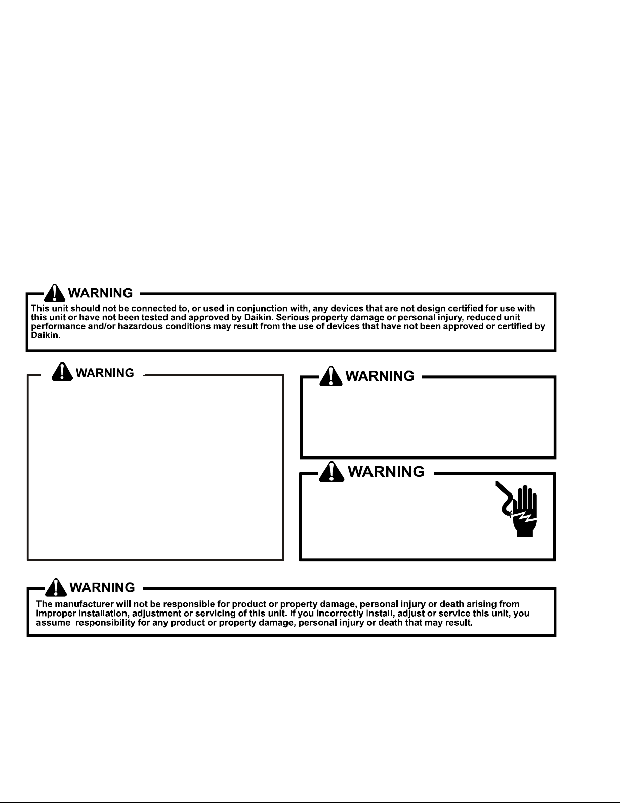
Do not store combustible materials or use gasoline
or other flammable liquids or vapors in the vicinity
of this appliance as property damage or personal
injury could occur. Have your contractor point out
and identify the various cut-off devices, switches,
etc., that serves your comfort equipment.
HIGH VOLTAGE!
Disconnect ALL power before
servicing or installing this unit.
Multiple power sources may be
present. Failure to do so may cause
prop er t y dam a ge, pe r sonal injury or de a t h.
To locate an authorized servicer, please consult your telephone book or the dealer from whom you purchased this
product. For further assistance, please contact:
CONSUMER INFORMATION LINE - DAIKIN BRAND PRODUCTS
TOLL FREE 1-855-770-5678 (U.S. only)
email us at: customerservice@daikincomfort.com
fax us at: (713) 856-1821
(Not a technical assistance line for dealers.)
Outside the U.S., call 1-713-861-2500
(Not a technical assistance line for dealers.)
Your telephone company will bill you for the call.
2
IMPORTANT INFORMATION
SAFE REFRIGERANT HANDLING
While these items will not cover every conceivable situation, they should serve as a useful guide.
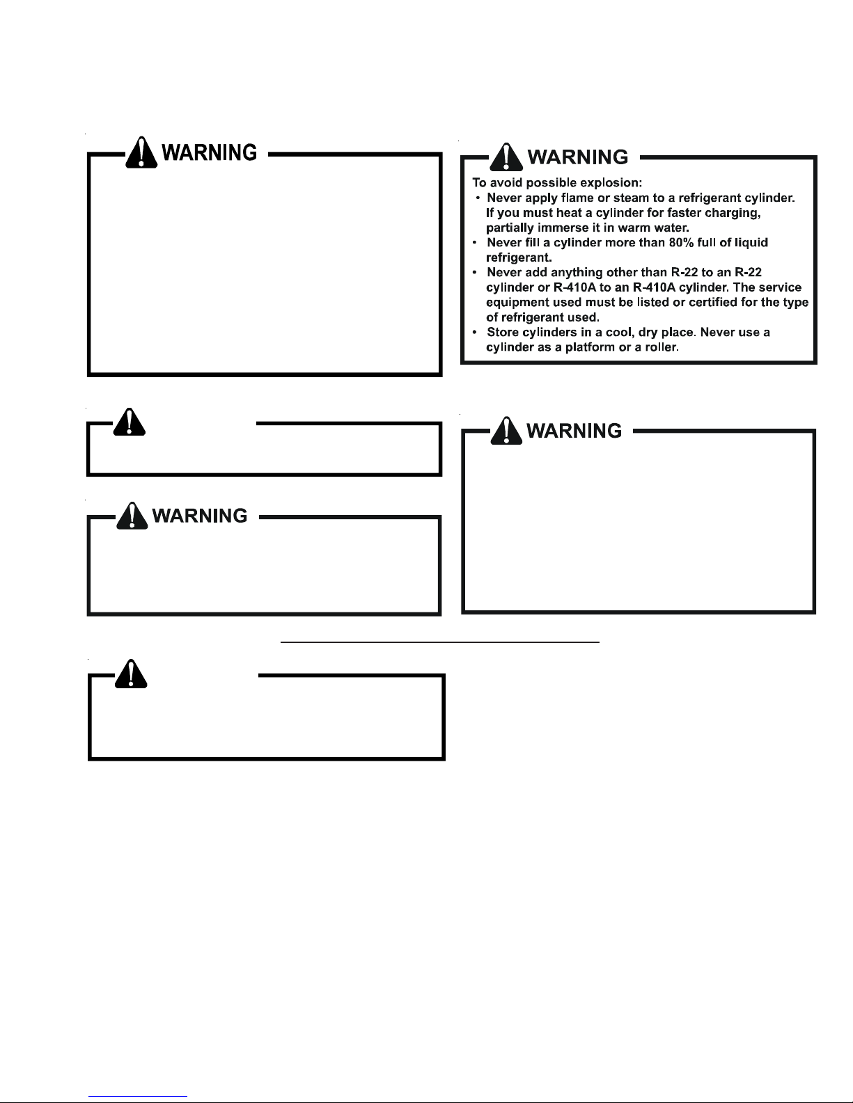
Refrigerants are heavier than air. They can "push out"
the oxygen in your lungs or in any enclosed space.To
avoid possible difficulty in breathing or death:
•
Never purge refrigerant into an enclosed room or
space. By law, all refrigerants must be reclaimed.
•
If an indoor leak is suspected, thoroughly ventilate
the area before beginning work.
• Liquid refrigerant can be very cold. To avoid possible
frostbite or blindness, avoid contact with refrigerant
and wea r gloves and gog gles. If liquid r efrige rant
does cont act your sk in or eyes, seek medic al help
immediately.
WARNING
To avoid possible injury, explosion or death, practice
safe handling of refrigerants.
The compre ssor POE oil for R-410A units is
extremely susceptible to moisture absorption and
could cause compressor failu r e. Do not leave system
open to atmosphere any longer than necessary
for insta llat i o n .
To avoid possible e xplosio n, use only returnabl e (n ot
disposable) service cylinders when removing refrigerant from a system.
• Ensure the cylinde r is f ree of damage which could
lead to a leak or explosio n .
• Ensure the hydrostatic test date does not exceed
5 years.
• Ensure the pressure rating meets or exceeds 400
lbs.
When in doubt, do not use cylinder.
WARNING
System contamina nts, improper se rvice procedure
and/or physical abuse affecting hermetic com pressor
electrical terminals may cause dangerous s ystem
venting.
The successful development of hermetically sealed refrigeration compressors has completely sealed the compressor's
moving parts and electric motor inside a common housing,
minimizing refrigerant leaks and the hazards sometimes
associated with moving belts, pulleys or couplings.
Fundamental to the design of hermetic compressors is a
method whereby electrical current is transmitted to the
compressor motor through terminal conductors which pass
through the compressor housing wall. These terminals are
sealed in a dielectric material which insulates them from the
housing and maintains the pressure tight integrity of the
hermetic compressor. The terminals and their dielectric
embedment are strongly constructed, but are vulnerable to
careless compressor installation or maintenance procedures and equally vulnerable to internal electrical short
circuits caused by excessive system contaminants.
In either of these instances, an electrical short between the
terminal and the compressor housing may result in the loss
of integrity between the terminal and its dielectric embedment. This loss may cause the terminals to be expelled,
thereby venting the vaporous and liquid contents of the
compressor housing and system.
A venting compressor terminal normally presents no danger
to anyone, providing the terminal protective cover is properly
in place.
If, however, the terminal protective cover is not properly in
place, a venting terminal may discharge a combination of
(a ) hot lubricating oil and refrigerant
(b ) flammable mixture (if system is contaminated
with air)
in a stream of spray which may be dangerous to anyone in the
vicinity. Death or serious bodily injury could occur.
Under no circumstances is a hermetic compressor to be
electrically energized and/or operated without having the
terminal protective cover properly in place.
See Service Section S-17 for proper servicing.
3

PRODUCT IDENTIFICA TION
r
y
y
The model number is used for positive identification of component parts used in manufacturing. Please use this number when
requesting service or parts information.
DCC090045 5 D***
1 2 3 4, 5, 6 7, 8, 9 10 11 12 13 14
Brand
DDaikin
Configuration
C Standard Efficiency XNo Options
Application
C Cooling X Standard Aluminized Heat Exchange
HHeat Pump S Stainle ss Steel Gas Heat Exchanger
Nominal Gross Cooling Capacit
036 3 Tons 102 8½ Ton s
048 4 Tons 120 10 Tons
060 5 Tons 180 15 Tons
072 6 Tons 240 20 Tons BBelt Drive
090 7½ T on s D Direct Dr ive
Nominal Heating Capacit
Gas/Electric A/C H/P Factory-Installed Electric Heat
180 180,000 BTU/h X XX No Heat 030 30 kW 1 208-230/1/60 ( Unit ed St ates) 4 460/ 3/60 (United Stat es)
300 300,00 0 BTU/h 016 15 kW 045 44 kW 3 208-230/3/60 (Un ited States) 5 400/3/50 (Russia Daikin B rand)
350 350,00 0 BTU/h 6 400/3/ 60 ( Saudi Ar ab ia) A 400/3 /50 (Russia Goodman Bran d)
B 400/3/50 (Kuwait) E 400/3/50 (Argentina)
See product specifications for heat size(s) available for each c apacit y.
A *
15 16
Revision Levels
Major & Minor
Factory-Install ed Optio ns
Factory-Install ed Optio ns
Factory-Install ed Optio ns
XNo Options
Supply Fan/Drive Type/Motors
Voltage
4

PRODUCT IDENTIFICA TION
Daikin Commer cial Multiposition Package Heat Pumps
Models Description
DCH[048-060]XXX6DXXXAA
DCH072XX X6BX XXAA
DCH048XXX6 DXXXAD
DCH060XXX6 DXXXAC
DCH072XX X6BX XXAC
Daikin Commercial Package Heat Pump, Multiposition heat pump units, 400V 3 Phase, 60 Hz Di rect Dr ive. Initial release
of Daikin branded models.
Daikin Commercial Package Heat Pump, Multiposition heat pump units, 400V 3 Phase, 60 Hz Di rect Dr ive. Initial release
of Daikin branded models.
Daikin Commercial Package Heat Pump, Multiposition heat pump units, 400V 3 Phase, 60 Hz Di rect Drive with Phase
Monitor.
Daikin Commercial Package Heat Pump, Multiposition heat pump units, 400V 3 Phase, 60 Hz Di rect Drive with Phase
Monitor.
DCH***XXX**XXX
These units have R410A refrigerant
5
PRODUCT IDENTIFICA TION
Daikin Co mmercia l M ultip o s it io n Pa c k a g e C oo le rs
Models Description
DCC[048-060]XXX6DXXXAA
DCC072XXX6BXXXAA
DCC[048-060]XXXBDXXXAA
DCC[048-060]XXX6DXXXAC Daikin Commercial Package Cooler, Multiposition cooling, 400V 3 Phase, 50 Hz Direct Drive with Phase Monitor.
DCC072XXX6BXXXAC Daikin Commercial Package Cooler, Multiposition cooling, 400V 3 Phase, 50 Hz Direct Drive with Phase Monitor.
Daikin Commercial Package Cooler, Multiposition cooling, 400V 3 Phase, 60 Hz Direct Drive. Initial release of 4-5 Ton
Daikin branded models.
Daikin Commercial Package Cooler, Multiposition cooling, 400V 3 Phase, 60 Hz Direct Drive. Initial release of 4-5 Ton
Daikin branded models.
Daikin Commercial Package Cooler, Multiposition cooling, 400V 3 Phase, 60 Hz Direct Drive. Initial release of Daikin
branded models with SASO level 2 regulations.
DCC***XXX**XXX
6
These units have R410A refrigerant

PRODUCT DESIGN
UNIT LOCATION
WARNING
O PREVENT POSSIBLE EQUIPMENT DAMAGE, PROPERTY DAMAGE, PERSONAL
T
INJURY OR DEATH, THE FOLLOWING BULLET P OINTS MUST BE OBSERVED
WHEN INSTALLING THE UNIT.
IMPORTANT NOTE: Remove wood shipping rails prior to
installation of the unit.
ALL INSTALLATIONS:
NOTE: Appliance is shipped from factory for vertical duct
application.
Proper installation of the unit ensures trouble-free operation.
Improper installation can result in problems ranging from
noisy operation to property or equipment damages, dangerous conditions that could result in injury or personal property
damage. Give this booklet to the user and explain it’s
provisions. The user should retain these instructions for future
reference.
• For proper flame pattern within the heat exchanger and
proper condensate drainage, the unit must be mounted
level.
• The flue outlet must be at least 12 inches from any
opening through which flue gases could enter a building,
and at least three feet above any forced air inlet located
within ten feet. The economizer/manual fresh air intake/
motorized fresh air intake and combustion air inlet
mounted on the unit are not affected by this restriction.
• To avoid possible corrosion of the heat exchanger, do not
locate the unit in an area where the outdoor air (i.e.
combustion air for the unit) will be frequently contaminated by compounds containing chlorine or fluorine.
Common sources of such compounds include swimming
pool chemicals and chlorine bleaches, paint stripper,
adhesives, paints, varnishes, sealers, waxes (which are
not yet dried) and solvents used during construction and
remodeling. Various commercial and industrial processes
may also be sources of chlorine/fluorine compounds.
• To avoid possible illness or death of the building occu-
pants, do NOT locate outside air intake device (economizer, manual fresh air intake, motorized fresh air intake)
too close to an exhaust outlet, gas vent termination, or
plumbing vent outlet. For specific distances required,
consult local codes.
• Allow minimum clearances from the enclosure for fire
protection, proper operation, and service access (see
unit clearances). These clearances must be permanently maintained.
• The combustion air inlet and flue outlet on the unit must
never be obstructed. If used, do not allow the economizer/manual fresh air damper/ motorized fresh air damper
to become blocked by snow or debris. In some climates
or locations, it may be necessary to elevate the unit to
avoid these problems.
• When the unit is heating, the temperature of the return air
entering the unit must be a minimum of 55° F.
GROUND LEVEL INSTALLATIONS ONLY:
• When the unit is installed on the ground adjacent to the
building, a level concrete (or equal) base is recommended. Prepare a base that is 3” larger than the
package unit footprint and a minimum of 3” thick.
• The base should also be located where no runoff of water
from higher ground can collect in the unit.
ROOF TOP INSTALLATIONS ONLY:
• To avoid possible property damage or personal injury, the
roof must have sufficient structural strength to carry the
weight of the unit(s) and snow or water loads as required
by local codes. Consult a structural engineer to determine the weight capabilities of the roof.
• The unit may be installed directly on wood floors or on
Class A, Class B, or Class C roof covering material.
• To avoid possible personal injury, a safe, flat surface for
service personnel should be provided.
• As indicated on the unit data plate, a minimum clearance
of 36” to any combustible material is required on the
furnace access side of the unit. All combustible materials must be kept out of this area.
• This 36” clearance must also be maintained to insure
proper combustion air and flue gas flow. The combustion
air intake and furnace flue discharge must not be blocked
for any reason, including blockage by snow.
• Adequate clearances from the furnace flue discharge to
any adjacent public walkways, adjacent buildings, building openings or openable windows must be maintained in
accordance with the latest edition of the National Fuel
Gas Code (ANSI Z223.1)
• Minimum horizontal clearance of 48” from the furnace flue
discharge to any electric meters, gas meters, regulators
and relief equipment is required.
UNIT PRECAUTIONS
• Do not stand or walk on the unit.
• Do not drill holes anywhere in panels or in the base
frame of the unit except where indicated. Unit access
panels provide structural support.
• Do not remove any access panels until unit has been
installed on roof curb or field supplied structure.
• Do not roll unit across finished roof without prior
approval of owner or architect.
• Do not skid or slide on any surface as this may damage
unit base. The unit must be stored on a flat, level
surface. Protect the condenser coil because it is
easily damaged.
7

PRODUCT DESIGN
ROOF CURB INSTALLATIONS ONLY:
Curb installations must comply with local codes and should
be done in accordance with the established guidelines of the
National Roofing Contractors Association.
Proper unit installation requires that the roof curb be firmly
and permanently attached to the roof structure. Check for
adequate fastening method prior to setting the unit on the
curb.
Full perimeter roof curbs are available from the factory and are
shipped unassembled. Field assembly, squaring, leveling
and mounting on the roof structure are the responsibility of the
installing contractor. All required hardware necessary for the
assembly of the sheet metal curb is included in the curb
accessory.
WARNING
O PREVENT POSSIBLE EQUIPMENT DAMAGE, PROPERTY DAMAGE, PERSONAL
T
INJURY OR DEATH, THE FOLLOWING BULLET POINTS MUST BE OBSERVED
WHEN INSTALLING THE UNIT.
• Sufficient structural support must be determined prior to
locating and mounting the curb and package unit.
• Ductwork must be constructed using industry guide-
lines. The duct work must be placed into the roof curb
before mounting the package unit. Our full perimeter
curbs include duct connection frames to be assembled
with the curb. Cantilevered type curbs are not available
from the factory.
• Curb insulation, cant strips, flashing and general roofing
material are furnished by the contractor.
The curbs must be supported on parallel sides by roof
members. The roof members must not penetrate supply and
return duct opening areas as damage to the unit might occur.
CLEARANCES
24”
Min.*
36” Min.
*
24”
Min.*
Unit Clearances
*In situations that have multiple units, a 48” minimum clearance
is required between the condenser coils.
Adequate clearance around the unit should be kept for safety,
service, maintenance, and proper unit operation. A total
clearance of 75” on the main control panel side of the unit is
recommended to facilitate possible fan shaft, coil, electric
heat and gas furnace removal. A clearance of 48” is
recommended on all other sides of the unit to facilitate
possible compressor removal, to allow service access and to
insure proper ventilation and condenser airflow. The unit must
not be installed beneath any obstruction. The unit should be
installed remote from all building exhausts to inhibit ingestion
of exhaust air into the unit fresh air intake.
NOTE: The unit and curb accessories are designed to
allow vertical duct installation before unit placement. Duct
installation after unit placement is not recommended.
CAUTION
ALL
CURBS LOOK SIMILAR
POSITIONING, CHECK JOB PLANS CAREFULLY AND VERIFY MARKINGS
ON CURB ASSEMBLY
SUPERSEDES INFORMATION SHOWN
. TO
AVOID INCORRECT CURB
. I
NSTRUCTIONS MAY VARY IN CURB STYLES AND
.
See the manual shipped with the roof curb for assembly and
installation instructions.
8
PROTRUSION
Inspect curb to ensure that none of the utility services
(electric) routed through the curb protrude above the curb.
ELECTRICAL WIRING
HIGH VOLTAGE!
D
ISCONNECT ALL POWER BEFORE SERVICING OR
INSTALLING THIS UNIT
BE PRESENT
DAMAGE, PERSONAL INJURY OR DEATH
. F
. M
AILURE TO DO SO MAY CAUSE PROPERTY
W ARNING
ULTIPLE POWER SOURCES MAY
.
PRODUCT DESIGN
WARNING
HIGH VOLTAGE!
O AVOID PERSONAL INJURY OR DEATH DUE TO
T
ELECTRICAL SHOCK, DO NOT TAMPER WITH FACTORY
WIRING
. THE
OF THESE UNITS ARE FACTORY-INSTALLED AND HAVE
BEEN THOROUGHLY TESTED PRIOR TO SHIPMENT
ONTACT YOUR LOCAL REPRESENTATIVE IF
C
ASSISTANCE IS REQUIRED
INTERNAL POWER AND CONTROL WIRING
.
.
CAUTION
TO
PREVENT DAMAGE TO THE WIRING, PROTECT WIRING FROM
SHARP EDGES
LOCAL CODES AND ORDINANCES
REMOVABLE ACCESS PANELS
. F
OLLOW NATIONAL ELECTRICAL CODE AND ALL
. DO
NOT ROUTE WIRES THROUGH
.
CAUTION
C
ONDUIT AND FITTINGS MUST BE WEATHER-TIGHT TO PREVENT
WATER ENTRY INTO THE BUILDING
.
For unit protection, use a fuse or HACR circuit breaker that
is in excess of the circuit ampacity, but less than or equal to
the maximum overcurrent protection device. DO NOT EXCEED THE MAXIMUM OVERCURRENT DEVICE SIZE
SHOWN ON UNIT DATA PLATE.
All line voltage connections must be made through weatherproof fittings. All exterior power supply and ground wiring
must be in approved weatherproof conduit.
The main power supply wiring to the unit and low voltage
wiring to accessory controls must be done in accordance
with these instructions, the latest edition of the National
Electrical Code (ANSI/NFPA 70), and all local codes and
ordinances. All field wiring shall conform with the temperature limitations for Type T wire (63°F/35°C rise).
The unit is factory wired for the voltage shown on the unit’s
data plate. Refer to model nomenclature in Appendix B for
voltage requirement for your unit.
NOTE: If supply voltage is 208V, lead on primary of transformer must be moved from the 230V to the 208V tap. Refer
to wiring diagram on unit for details.
Main power wiring should be sized for the minimum wire
ampacity shown on the unit’s database. Size wires in
accordance with the ampacity tables in Article 310 of the
National Electrical Code. If long wires are required, it may be
necessary to increase the wire size to prevent excessive
voltage drop. Wires should be sized for a maximum of 3%
voltage drop.
CAUTION
O AVOID PROPERTY DAMAGE OR PERSONAL INJURY DUE TO FIRE, USE
T
ONLY COPPER CONDUCTORS.
CAUTION
O PREVENT IMPROPER AND DANGEROUS OPERATION DUE TO WIRING ERRORS,
T
LABEL ALL WIRES PRI OR TO DISCONNECTION WH EN SERVICING CONTRO LS.
ERIFY PROPER OPERATION AFTER SERVICING.
V
NOTE: A weather-tight disconnect switch, properly sized
for the unit total load, must be field or factory installed. An
external field supplied disconnect may be mounted on the
exterior panel.
Ensure the data plate is not covered by the field-supplied
disconnect switch.
• Some disconnect switches are not fused. Protect the
power leads at the point of distribution in accordance with
the unit data plate.
• The unit must be electrically grounded in accordance
with local codes or, in the absence of local codes, with
the latest edition of the National Electrical Code (ANSINFPA 70). A ground lug is provided for this purpose. Size
grounding conductor in accordance with Table 250-95 of
the National Electrical Code. Do not use the ground lug
for connecting a neutral conductor.
• Connect power wiring to the compressor contactor closest to the entrance located within the main control box or
to electrical power block, if equipped.
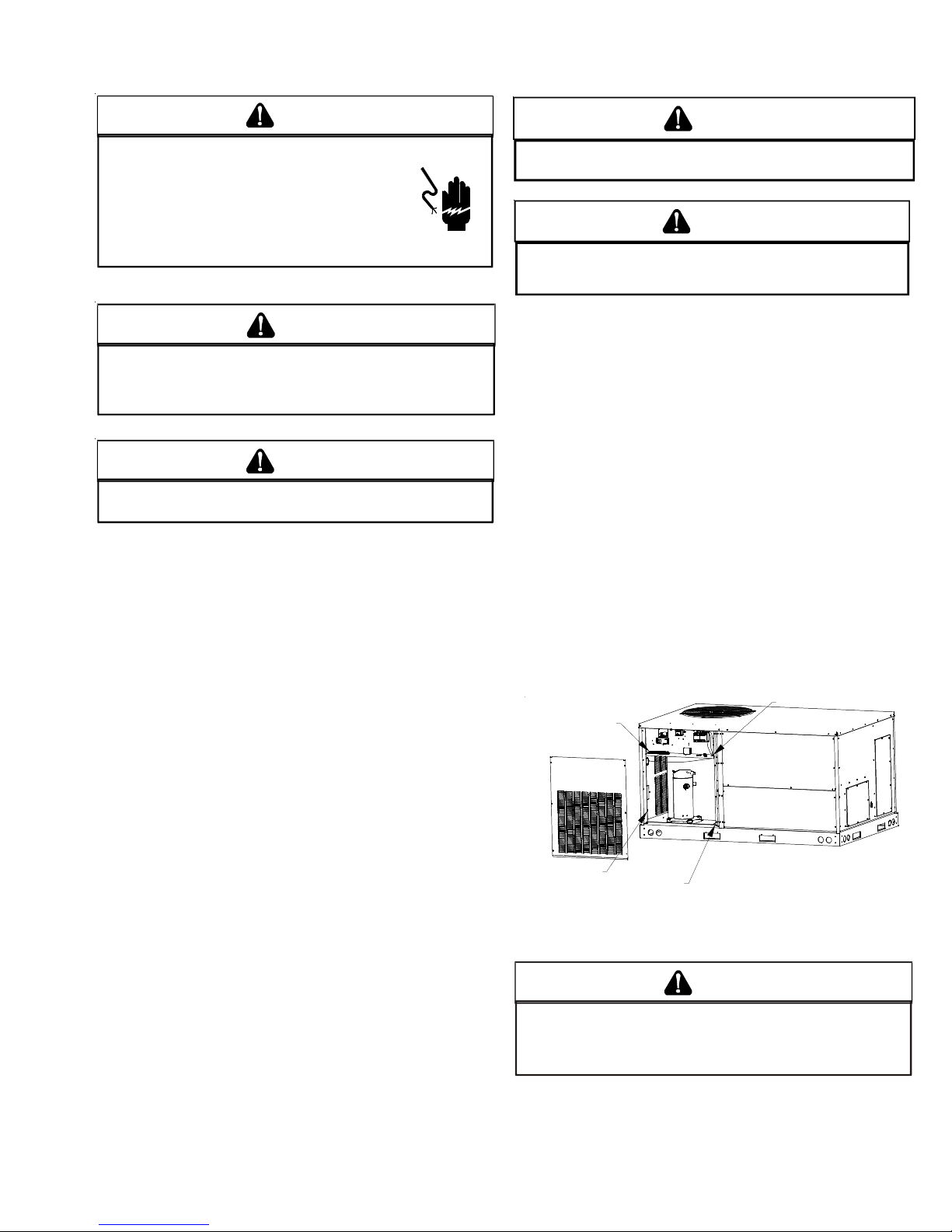
MAIN POWER
LOW VOLTAGE
BLOCK
LOW VOLTAGE
ENTRANCE
POWER THRU
THE CURB
Power and Low Voltage Block Connections
W ARNING
F
AILURE OF UNIT DUE TO OPERATION ON IMPROPER LINE VOLTAGE
OR WITH EXCESSIVE PHASE UNBALANCE CONSTITUTES PRODUCT
ABUSE AND MAY CAUSE SEVERE DAMAGE TO THE UNIT ELECTRICAL
COMPONENTS
.
9

PRODUCT DESIGN
AREAS WITHOUT CONVENIENCE OUTLET
It is recommended that an independent 115V power source
be brought to the vicinity of the roof top unit for portable lights
and tools used by the service mechanic.
NOTE: Refer to local codes for requirements. These outlets
can also be factory installed.
UNITS INSTALLED ON ROOF TOPS
Main power and low voltage wiring may enter the unit through
the condenser end of unit or through the roof curb. Install
conduit connectors at the desired entrance locations. External connectors must be weatherproof. All holes in the unit
base must be sealed (including those around conduit nuts) to
prevent water leakage into building. All required conduit and
fittings are to be field supplied.
Supply voltage to roof top unit must not vary by more than
10% of the value indicated on the unit data plate. Phase
voltage unbalance must not exceed 2%. Contact your local
power company for correction of improper voltage or phase
unbalance.
HIGH VOLTAGE ENTRANCE
(REMOVE PLUG)
12 3/8”
30 1/4”*
* (6 Ton - 34 1/4”)
1:4
LOW VOLTAGE ENTRANCE
3.5 DIA.
POWER THRU
THE CURB
4 1/2”
47 1/2”
7 1/2”
Electrical Entrance and Thru Curb
Unit is equipped with a Low Voltage Terminal Block and has
Single Point wiring to the contactor or power block, if
equipped.
LOW VOLTAGE CONTROL WIRING
1. A 24V thermostat must be installed for unit operation. It
may be purchased with the unit or field -supplied. Thermostats may be programmable or electromechanical as
required.
2. Locate thermostat or remote sensor in the conditioned
space where it will sense average temperature. Do not
locate the device where it may be directly exposed to
supply air, sunlight or other sources of heat. Follow
installation instructions packaged with the thermostat.
3. Use #18 AWG wire for 24V control wiring runs not
exceeding 75 feet. Use #16 AWG wire for 24V control
wiring runs not exceeding 125 feet. Use #14 AWG wire
for 24V control wiring runs not exceeding 200 feet. Low
voltage wiring may be National Electrical Code (NEC)
Class 2 where permitted by local codes.
4. Route thermostat wires from sub-base terminals to the
unit. Control wiring should enter through the condenser
panel opening or through curb indicated in “Electrical
Entrance” figure. Connect thermostat and any accessory
wiring to low voltage terminal block TB1 in the main
control box.
10
NOTE: Field-supplied conduit may need to be installed
depending on unit/curb configuration. Use #18 AWG solid
conductor wire whenever connecting thermostat wires to
terminals on sub-base. DO NOT use larger than #18 AWG
wire. A transition to #18 AWG wire may be required before
entering thermostat sub-base.
NOTE: Refer to unit wiring diagrams for thermostat
hookups.
SYSTEM OPERATION
Typical Package Cooling or Package Gas
DCC***XXX**XXX
Restrictor Orifice Assembly in Cooling Operation
In the cooling mode the orifice is pushed into its seat forcing refrigerant to flow through the metered hole in the center of the
orifice.
11

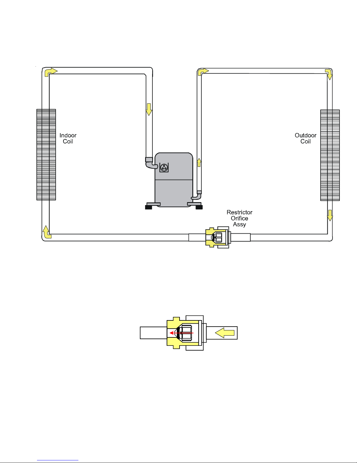
SYSTEM OPERATION
Typical Heat Pump System in Cooling
DCH***XXX**XXX
Reversing Valve
(Energized)
Indoor
Coil
Outdoor
Coil
Accumulator
Indoor
Coil
Accumulator
12
Reversing Valve
(De-Energized)
Outdoor
Coil

SYSTEM OPERATION
CIRCULATING AIR AND FILTERS
DUCTWORK
The supply duct from the unit through a wall may be installed
without clearance. However, minimum unit clearances must
be maintained (see “Clearances” section). The supply duct
should be provided with an access panel large enough to
inspect the air chamber downstream of the heat exchanger.
A cover should be tightly attached to prevent air leaks.
Ductwork dimensions are shown in the roof curb installation
manual.
If desired, supply and return duct connections to the unit may
be made with flexible connections to reduce possible unit
operating sound transmission.
VENTING
NOTE: Venting is self-contained.
CONDENSATE DRAIN CONNECTION
CONDENSATE DRAIN CONNECTION
A 3/4” female NPT drain connection is supplied on the end of
the unit and bottom of the drain pan for condensate piping. An
external trap must be installed for proper condensate drainage.
DRAIN
CONNECTION
UNIT 2" MIN IMUM
FLEXIBLE
TUBING-HOSE
OR PIPE
A POSIT IVE L I QUID
SEAL IS REQU IRE D
3" MINIMUM
Drain Connection
Install condensate drain trap as shown. Use 3/4" drain line
and fittings or larger. Do not operate without trap.
HORIZONTAL DRAIN
Drainage of condensate directly onto the roof may be acceptable; refer to local code. It is recommended that a small drip
pad of either stone, mortar, wood or metal be provided to
prevent any possible damage to the roof.
CLEANING
Due to the fact that drain pans in any air conditioning unit will
have some moisture in them, algae and fungus will grow due
to airborne bacteria and spores. Periodic cleaning is necessary to prevent this build-up from plugging the drain.
STARTUP, ADJUSTMENTS, AND CHECKS
WARNING
HIGH VOLTAGE!
O AVOID PERSONAL INJURY OR DEATH DUE TO
T
ELECTRICAL SHOCK, B
THE BUILDING ELECTRICAL GROUND BY USE OF THE
GROUNDING TERMINAL PROVIDED OR OTHER
ACCEPTABLE MEANS
SERVICING OR INSTALLING THIS UNIT
OND THE FRAME OF THIS UNIT TO
. D
ISCONNECT ALL POWER BEFORE
.
CAUTION
TO
PREVENT PROPERTY DAMAGE OR PERSONAL INJURY
START THE UNIT UNTIL ALL NECESSARY PRE-CHECKS AND TESTS
HAVE BEEN PERFORMED
.
, DO
NOT
WARNING
MOVING MACHIN ERY HAZARD!
T
O PREVENT POSSIBLE PERSONAL INJURY OR DEATH, DISCONNECT
POWER TO THE UNIT AND PADLOCK IN THE
SERVICNG FANS
.
“OFF”
POSITION BEFORE
CONTRACTOR RESPONSIBILITY
The installing contractor must be certain that:
• All supply and return air ductwork is in place, properly
sealed, and corresponds with installation instructions.
• All thermostats are mounted and wired in accordance
with installation instructions.
• All electric power, all gas, hot water or steam line
connections, and the condensate drain installation
have been made to each unit on the job. These main
supply lines must be functional and capable of operating all units simultaneously.
• Requirements are met for venting and combustion air.
• Air filters are in place.
• Input rate and temperature rise are adjusted per rating
plate.
• Return air temperature is maintained between 55°F
(13°C) and 80°F (27°C).
ROOF CURB INSTALLATION CHECK
Inspect the roof curb for correct installation. The unit and curb
assembly should be level. Inspect the flashing of the roof
mounting curb to the roof, especially at the corners, for good
workmanship. Also check for leaks around gaskets. Note
any deficiencies in a separate report and forward to the
contractor.
13

SYSTEM OPERATION
OBSTRUCTIONS, FAN CLEARANCE AND WIRING
Remove any extraneous construction and shipping materials
that may be found during this procedure. Rotate all fans
manually to check for proper clearances and that they rotate
freely. Check for bolts and screws that may have jarred loose
during shipment to the job site. Retighten if necessary. Retighten all electrical connections.
FIELD DUCT CONNECTIONS
Verify that all duct connections are tight and that there is no
air bypass between supply and return.
FILTER SECTION CHECK
Remove filter section access panels and check that filters are
properly installed. Note airflow arrows on filter frames.
AIR FLOW ADJUSTMENTS
When the final adjustments are complete, the current draw of
the motor should be checked and compared to the full load
current rating of the motor. The amperage must not exceed
the service factor stamped on the motor nameplate. The total
airflow must not be less than that required for operation of the
electric heaters or the furnace.
If an economizer is installed, check the unit operating
balance with the economizer at full outside air and at
minimum outside air.
NOTE: Airflow setting below 350 CFM/Ton is not
recommended, as evaporator freezing or poor unit
performance is possible.
PSC MOTOR
Adjust the CFM for the unit by changing the speed tap of the
indoor blower motor at the heat or cool tap on the control
board connection with the one of the speed taps on “M1” or
“M2” (Black-High Speed, Blue-Medium Speed, Red-Low
Speed).
EEM Motor
Adjust the CFM for the unit by changing the position of the low
voltage leads on the motor terminal block. Green is for Fan
Only. Yellow is for Cooling and Heat Pump Heating.NOTE: If
more than one lead is energized simultaneously, the motor
will run at the higher speed.
SET EVAPORATOR FAN RPM
Actual RPM’s must be set and verified with a tachometer or
strobe light. Refer to Appendices A and B for basic unit fan
RPM. Refer also to “Airflow” section of this manual. With
disconnect switch open, disconnect thermostat wires from
terminals Y and W. This will prevent heating and mechanical
cooling from coming on. Place a jumper wire across terminals
R and G at TB1 terminal block. Close disconnect switch;
evaporator fan motor will operate so RPM can be checked.
For gas heat units, the airflow must be adjusted so that the
air temperature rise falls within the ranges given stated on
Data Plate.
14
EVAPORATOR FAN ROTATION CHECK (THREE PHASE MODELS
ONLY)
Check that fan rotates clockwise when viewed from the drive
side of unit and in accordance with rotation arrow shown on
blower housing. If it does not, reverse any two incoming power
cables at Single Point Power Block. In this case, repeat
bearing check.
Do not attempt to change load side wiring. Internal wiring
assures all motors and compressors will rotate in correct
direction once evaporator fan motor rotation check has been
made.
ELECTRICAL INPUT CHECK
Make preliminary check of evaporator fan ampere draw and
verify that motor nameplate amps are not exceeded. A final
check of amp draw should be made upon completion of air
balancing of the duct system.
BELT DRIVE MODELS ONLY
The drive on the supply fan is typically set in the middle of the
RPM range. The drive motor sheave pitch diameter is field
adjustable for the required airflow.
Upon completion of the air flow balancing, we recommend
replacing the variable pitched motor sheave with a properlysized fixed sheave. A matching fixed sheave will provide
longer belt and bearing life and vibration free operation.
Initially, it is best to have a variable pitched motor sheave for
the purpose of airflow balancing, but once the balance has
been achieved, fixed sheaves maintain alignment and minimize vibration more effectively. For direct drive units, move fan
speed wire.
BEARING CHECK
Prior to energizing any fans, check and make sure that all
setscrews are tight so that bearings are properly secured to
shafts.
NORMAL SEQUENCE OF OPERATION
COOLING
Begin with power turned off at all disconnects.
1. Turn thermostat system switch to “Cool,” and fan switch
to “Auto” and turn temperature setting as high as it will go.
2. Inspect all registers and set them to the normal open
position.
3. Turn on the electrical supply at the disconnect.
4. Turn the fan switch to the “ON” position. The blower
should operate after a 7 second delay.
5. Turn the fan switch to “Auto” position. The blower should
stop after a 65 second delay.
SYSTEM OPERATION
6. Slowly lower the cooling temperature until the unit starts.
The compressor, blower and fan should now be operating. Allow the unit to run 10 minutes, make sure cool air
is being supplied by the unit.
7. Turn the temperature setting to the highest position,
stopping the unit. The indoor blower will continue to run
for 65 seconds.
8. Turn the thermostat system switch to “OFF” and disconnect all power when servicing the unit.
WA RNING
HIGH VOLTAGE!
D
ISCONNECT ALL POWER BEFORE SERVICING OR
INSTALLING THIS UNIT
BE PRESENT
DAMAGE, PERSONAL INJURY OR DEATH
. F
. M
AILURE TO DO SO MAY CAUSE PROPERTY
ULTIPLE POWER SOURCES MAY
.
HEAT PUMP
9. Check the cooling mode for the heat pump in the same
manner as above. The reversing valve is energized when
the thermostat is placed in the cooling position. A
clicking sound should be noticeable from the reversing
valve. By lowering the temperature setting to call for
cooling, the contractor is energized. The compressor,
blower and fan should then be running. After the cooling
mode is checked out, turn the thermostat system switch
to “OFF”.
10.Turn the thermostat system switch to “HEAT” and fan
switch to “AUTO”.
11.Slowly raise the heating temperature setting. When the
heating first stage makes contact, stop raising the
temperature setting.. The compressor, blower and fan
should now be running with the reversing valve in the deenergized (heating) position. After giving the unit time to
settle out, make sure the unit is supplying heated air.
12.If the outdoor ambient is above 80°F, the unit may trip on
its high pressure cut out when on heating. The compressor should stop. The heating cycle must be thoroughly
checked, so postpone the test to another day when
conditions are more suitable but-DO NOT FAIL TO TEST.
If the outdoor ambient is low and the unit operates
properly on the heating cycle, you may check the
pressure cutout operation by blocking off the indoor
return air until the unit trips.
13.If unit operates properly in the heating cycle, raise the
temperature setting until the heating second stage makes
contact. Supplemental resistance heat, if installed should
now come on. Make sure it operates properly.
NOTE: If outdoor thermostats are installed the outdoor
ambient must be below the set point of these thermostats for the heaters to operate. It may be necessary to
jumper these thermostats to check heater operation if
outdoor ambient is mild.
14.For thermostats with emergency heat switch, return to
step 11. The emergency heat switch is located at the
bottom of the thermostat. Move the switch to emergency
heat. The heat pump will stop, the blower will continue to
run, all heaters will come on and the thermostat emergency heat light will come on.
15.If checking the unit in the wintertime, when the outdoor
coil is cold enough to actuate the defrost control, observe
at least one defrost cycle to make sure the unit defrosts
completely.
HEAT PUMP OPERATION
COOLING CYCLE
When the heat pump is in the cooling cycle, it operates
exactly as a Summer Air Conditioner unit. In this mode, all the
charts and data for service that apply to summer air conditioning apply to the heat pump. Most apply on the heating cycle
except that “condenser” becomes “evaporator”, “evaporator”
becomes “condenser”, “cooling” becomes “heating”.
HEATING CYCLE
The heat pump operates in the heating cycle by redirecting
refrigerant flow through the refrigerant circuit external to the
compressor. This is accomplished with through the reversing
valve. Hot discharge vapor from the compressor is directed to
the indoor coil (evaporator on the cooling cycle) where the
heat is removed, and the vapor condenses to liquid. It then
goes through the expansion device to the outdoor coil
(condenser on the cooling cycle) where the liquid is evaporated, and the vapor goes to the compressor.
When the solenoid valve coil is operated either from heating
to cooling or vice versa, the piston in the reversing valve to the
low pressure (high pressure) reverse positions in the reversing valve.
The following figures show a schematic of a heat pump on the
cooling cycle and the heating cycle. In addition to a reversing
valve, a heat pump is equipped with an expansion device and
check valve for the indoor coil, and similar equipment for the
outdoor coil. It is also provided with a defrost control system.
The expansion devices are flowrator distributors and perform
the same function on the heating cycle as on the cooling
cycle. The flowrator distributors also act as check valves to
allow for the reverse of refrigerant flow.
15

SYSTEM OPERATION
DEFROST CONTROL
During operation the power to the circuit board is controlled
by a temperature sensor, which is clamped to a feeder tube
entering the outdoor coil. Defrost timing periods of 30,60 and
90 minutes may be selected by connecting the circuit board
jumper to 30, 60 and 90 respectively. Accumulation of time
for the timing period selected starts when the sensor closes
(approximately 31° F), and when the wall thermostat calls for
heat. At the end of the timing period, the unit’s defrost cycle
will be initiated provided the sensor remains closed. When
the sensor opens (approximately 75° F), the defrost cycle is
terminated and the timing period is reset. If the defrost cycle
is not terminated due to the sensor temperature, a ten minute
override interrupts the unit’s defrost period.
REFRIGERATION SYSTEM CHECKS
Ensure the hold-down bolts on the compressor are secure
and have not vibrated loose during shipment. Check that
vibration grommets have been installed. Visually check all
piping and clamps. The entire refrigeration system has been
factory charged and tested, making it unnecessary to field
charge. Factory charges are shown on the unit nameplate.
When the heat pump is on the heating cycle, the outdoor coil
is functioning as an evaporator. The temperature of the
refrigerant in the outdoor coil must be below the temperature
of the outdoor air in order to extract heat from the air. Thus,
the greater the difference in the outdoor temperature and the
outdoor coil temperature, the greater the heating capacity of
the heat pump. This phenomenon is a characteristic of a heat
pump. It is a good practice to provide supplementary heat for
all heat pump installations in areas where the temperature
drops below 45° F. It is also a good practice to provide
sufficient supplementary heat to handle the entire heating
requirement should there be a component failure of the heat
pump, such as a compressor, or refrigerant leak, etc.
Since the temperature of the refrigerant in the outdoor coil on
the heating cycle is generally below freezing point, frost forms
on the surfaces of the outdoor coil under certain weather
conditions of temperature and relative humidity. Therefore, it
is necessary to reverse the flow of the refrigerant to provide hot
gas in the outdoor coil to melt the frost accumulation. This is
accomplished by reversing the heat pump to the cooling
cycle. At the same time, the outdoor fan stops to hasten the
temperature rise of the outdoor coil and lessen the time
required for defrosting. The indoor blower continues to run and
the supplementary heaters are energized.
FINAL SYSTEM CHECKS
1. Check to see if all supply and return air grilles are
adjusted and the air distribution system is balanced for
the best compromise between heating and cooling.
2. Check for air leaks in the ductwork. See Sections on Air
Flow Adjustments.
3. Make sure the unit is free of “rattles”, and the tubing in the
unit is free from excessive vibration. Also make sure
tubes or lines are not rubbing against each other or sheet
metal surfaces or edges. If so, correct the trouble.
4. Set the thermostat at the appropriate setting for cooling
and heating or automatic changeover for normal use.
5. Be sure the Owner is instructed on the unit operation,
filter, servicing, correct thermostat operation, etc.
16

SCHEDULED MAINTENANCE
MAINTENANCE
WARNING
HIGH VOLTAGE!
D
ISCONNECT ALL POWER BEFORE SERVICING OR
INSTALLING THIS UNIT
BE PRESENT
DAMAGE, PERSONAL INJURY OR DEATH
. F
. M
AILURE TO DO SO MAY CAUSE PROPERTY
ULTIPLE POWER SOURCES MAY
.
WARNING
TO
PREVENT PERSONAL INJURY OR DEATH DUE TO IMPROPER
INSTALLATION, ADJUSTMENT, ALTERATION, SERVICE OR
MAINTENANCE, REFER TO THIS MANUAL
ASSISTANCE OR INFORMATION, CONSULT A QUALIFIED INSTALLER
SERVICE AGENCY OR THE GAS SUPPLIER
. FOR
CAUTION
S
HEET METAL PARTS, SCREWS, CLIPS AND SIMILAR ITEMS INHERENTLY
HAVE SHARP EDGES, AND IT IS NECESSARY THAT THE INSTALLER AND
SERVICE PERSONNEL EXERCISE CAUTION
Preventive maintenance is the best way to avoid unnecessary
expense and inconvenience. Have this system inspected at
regular intervals by qualified service personnel, at least twice
a year. Routine maintenance should cover the following
items:
1. Tighten all belts, set screws, and wire connections.
2. Clean evaporator and condenser coils mechanically or
with cold water, if necessary. Usually any fouling is only
matted on the entering air face of the coil and can be
removed by brushing.
3. Lubricate motor bearings.
4. Align or replace belts as needed.
5. Replace filters as needed (see below).
6. Check for blockage of condensate drain.
7. Check power and control voltages.
8. Check running amperage.
9. Check operating temperatures and pressures.
10.Check and adjust temperature and pressure controls.
11.Check and adjust damper linkages.
12.Check operation of all safety controls.
13.Examine gas furnaces (see below and the User’s Information Manual).
14.Check condenser fans and tighten set screws.
.
.
ADDITIONAL
,
FILTERS
CAUTION
TO PREVENT PROPERTY DAMAGE DUE TO FIRE AND LOSS OF
EQUIPMENT EFFICIENCY OR EQUIPMENT DAMAGE DUE TO DUST AND LINT
BUILD UP ON INTERNAL PARTS, NEVER OPERATE UNIT WITHOUT AN AIR
FILTER INSTALLED IN THE RETURN AIR SYSTEM.
Every application may require a different frequency of replacement of dirty filters. Filters must be replaced at least every
three (3) months during operating seasons.
Dirty filters are the most common cause of inadequate
heating or cooling performance. Filter inspection should be
made at least every two months; more often if necessary
because of local conditions and usage.
Dirty throwaway filters should be discarded and replaced with
a new, clean filter.
Disposable return air filters are supplied with this unit. See the
unit Specification Sheet or the correct size and part number.
To remove the filters, remove the filter access panel on return
side of the unit.
CABINET FINISH MAINTENANCE
Use a fine grade automotive wax on the cabinet finish to
maintain the finish’s original high luster. This is especially
important in installations with extended periods of direct
sunlight.
CLEAN OUTSIDE COIL (QUALIFIED SERVICER ONLY)
The coil with the outside air flowing over it should be inspected
annually and cleaned as frequently as necessary to keep the
finned areas free of lint, hair and debris.
CONDENSER AND INDUCED DRAFT MOTORS
Bearings on the condenser fan motors and the combustion
fan motor are permanently lubricated. No additional oiling is
required.
LUBRICATION
The fan shaft bearings, the 1 to 2 HP supply fan motors, the
condenser fan motors and compressors are permanently
lubricated.
FUNCTIONAL PARTS
Refer to the unit Parts Catalog for a list of functional parts.
Parts are available from your distributor.
17

SERVICING
C
,
S-200,20
COOLING ANALYSIS CHART
Complaint
POSSIB LE CAUSE
DOTS IN ANALYSIS
GUIDE INDICATE
"POSSIBLE CAUSE"
Power F a i lure
Blown Fuse
Unbalanced Power, 3PH
Loose C o nne ct ion
Shorted or Broken Wires
Open Fan Overload
Faulty Thermostat
Faulty Transformer
Shorted or Open Capacitor
Inter n al Compr ess or O verload Open
Shorted or Grounded Compressor
Compressor Stuck
Faulty Compressor Contac tor
Faulty Fan Relay
Open Control Circuit
Low Voltage
Faulty Evap . Fan Motor
Shorted or Grounded Fan Motor
Im proper Cooling Anticipator
Shortage of Refrige r ant
Res tr i cted Liqu i d Line
Dirty Air Filter
Dirty Indoor Coil
Insuffic ient air a cross Indoor Coi l
Too mu ch air acros s Indoor Coil
Overcharge of Refrigerant
Dirty Outdoor Coil
Noncondensibles
Rec i rcul at ion of Condensing Ai r
Infi ltration of Outdoor Air
Im p ro perly Loc ated Therm osta t
Air F low Un balanc ed
Syst em U ndersized
Bro ken Internal P ar ts
Bro ken Val ves
Inef fic i ent Compresso r
E xpans i o n D e vice Re s tricted
Loose H o l d -down Bol ts
Flowrator Not Seating Properly
Compr ess or runs - goes of f on overload
Unsatisfactory
Compressor cycles on overload
Syst em runs continuo usly - little cooling
Cooling
No Cooling
SYMPTOM
System will not start
Compresso r will not start - fan runs
Com p. an d C on d. Fan wi ll no t st ar t
Evaporator fan will not start
Condenser fan will not start
•
•••
•••
•••
••••••
••
••• •
••
•••••
•
••
•••
•••
•
•
•••
••
••
••
•• •
•• • •
••••
••••
••••
•• • ••
••• • •
•• • •
•• • •
•••
••
••
••
•••
••
••• • • •
••
Cooling Cycle
•
System
Operating
Pressures
Test M et hod
Remedy
See Serv ic e Proced u re Re f.
To o c ool and the n too warm
Not coo l enough on w ar m days
Certain areas too cool, others too warm
Co m pr e s sor is no i s y
Low su ction pr essure
High suc ti on pres sure
High he ad pressure
Test Voltage S-1
Inspect Fus e Size & Type S-1
Test Voltage S-1
Inspect Connectio n - Ti gh te n S-2 , S- 3
Te st Ci rcu its Wi th Ohmmete r S-2 , S-3
Test Continuity of Overloa d S-17 A
Test Continuity of Thermostat & W iring S-3
Check Control Circuit with Volt meter S-4
Test C apa citor S- 15
Test Continuity of Overloa d S-17 A
Test Motor Windings S-17B
Use Test Cord S-17D
Test Continuit y of Coil & Contacts S-7, S-8
Test Continuit y of Coil And Contacts S-7
Test Control Circuit with Voltmeter S-4
Test Voltage S-1
Repair or Replace S-16
Test Motor Windings S-16
Check R esi st an ce of Anticipator S-3B
Test For Leaks, Add Refrigerant S-101,103
Remove Restriction, Replace Restricted Part S-112
In spec t Fil ter -Cle an or Replace
Inspect Coil - Clean
heck Blower Speed and Rotation, Belt, Pulleys
Reduc e Bl o wer Speed, C heck Pul ley Adjust m e nt S-205, 20 7
•
Recover Part of Charge S-113
Inspect Coil - Clean
Recove r C harge, Ev acua te, Re ch ar ge S-114
Remove Obstruction to Air Flow
Check Windows, Doors, V ent Fans, Etc.
Relocate Thermostat
Readjust Air Volume Dampers
Refigure Cooling Load
•
•
Repl ace Com pressor S-115
Test Compressor Efficiency
Test Compressor Efficiency S- 104
Remo ve Restric tion, Replace Expansi on Dev i ce 111
Ti ghten Bo lts
Check Flow ra to r & Se at or Replace F l owrator S-111
5,
S-104
18
SERVICING
Table of Contents
S-1 Checking Voltage.......................................... 2 0
S-2 Checking Wiring............................................ 21
S-3 Checking Thermostat, Wiring & Anticipator .. 21
S-3A Thermostat & Wiring ..................................... 21
S-3B Cooling Anticipator........................................ 21
S-4 Checking Transformer & Control Circuit ....... 21
S-7 Checking Contactor and/or Relays ................ 22
S-8 Checking Contactor Contacts .......................22
S-9 Checking Fan Relay Contact ........................ 23
S-11 Checking Loss of Charge Protection ............. 24
S-12 Checking High Pressure Control ................... 24
S-13 Checking Low Pressure Control .................... 24
S-15 Checking Capacitor......................................25
S-15A Resistance Check......................................... 25
S-15B Capacitance Check ...................................... 25
S-16 Checking Motors........................................... 26
S-16A Checking Fan & Blower Motor
Windings (PSC Motors) ............................... 26
S-16D Checking EEM Motors .................................. 26
S-17 Checking Compressor Windings .................. 27
S-17A Resistance Test ............................................27
S-17B Ground Test .................................................. 27
S-17D Operation Test ..............................................28
S-18 Testing Crankcase Heater (optional item).....28
S-18A Crankcase Heater Thermostat ...................... 28
S-21 Checking Reversing Valve & Solenoid.......... 28
S-24 Testing Defrost Control .................................29
S-25 Testing Defrost Thermostat ........................... 29
S-50 Checking Heater Limit Control(s).................. 30
S-100 Refrigeration Repair Practice ....................... 30
S-101 Leak Testing ................................................. 30
S-102 Evacuation .................................................... 31
S-103 Charging.......................................................32
S-104 Checking Compressor Efficiency ................. 33
S-106 Overfeeding .................................................. 33
S-108 Checking Superheat ..................................... 33
S-111 Fixed Orifice Restriction Devices.................. 36
S-112 Checking Restricted Liquid Line ................... 36
S-113 Refrigerant Overcharge ................................ 36
S-114 Non-condensables ........................................ 36
S-115 Compressor Burnout.....................................36
S-200 Checking External Static Pressure ...............37
S-201 Checking Temperature Rise .........................39
S-205 Checking Belt Tension .................................. 38
S-206 Indoor Fan Rotation Check ........................... 39
S-207 Motor Sheave Adjustment ............................. 39
HIGH VOLTAGE !
Disconnect ALL power before servicing or installing this unit. Multiple power sources
may be present. Failure to do so may cause property damage, person al inj ury or death.
19

SERVICING
S-1 CHECKING VOLTAGE
HIGH VOLTAGE!
Disconnect ALL power before servicing
or insta llin g th is un it. M ult iple powe r
sources may be present. Failure to do so
may cause property damage, personal injury
or death.
1. Remove doors, control panel cover, etc. from unit being
tested.
With power ON:
WARNING
Line Voltage now present.
2. Using a voltmeter, measure the voltage across terminals
L1 and L2 of the contactor for single phase units, and L3,
for 3 phase units.
3. No reading - indicates open wiring, open fuse(s) no power
or etc. from unit to fused disconnect service. Repair as
needed.
4. With ample voltage at line voltage connectors, energize
the unit.
5. Measure the voltage with the unit starting and operating,
and determine the unit Locked Rotor Voltage.
Locked Rotor Voltage is the actual voltage available at
the compressor during starting, locked rotor, or a stalled
condition. Measured voltage should be above minimum
listed in chart below.
To measure Locked Rotor Voltage attach a voltmeter to
the run "R" and common "C" terminals of the compressor,
or to the T1 and T2 terminals of the contactor. Start the unit
and allow the compressor to run for several seconds, then
shut down the unit. Immediately attempt to restart the
unit while measuring the Locked Rotor Voltage.
6. Voltmeter should read within the voltage tabulation as
shown. If the voltage falls below the minimum voltage,
check the line wire size. Long runs of undersized wire can
cause low voltage. If wire size is adequate, notify the local
power company in regards to either low or high voltage.
Unit Supply Voltage
Voltage Min. Max.
208/230 198 253
400 360 440
460 437 506
575 546 604
Three phase units require a balanced 3 phase power supply
to operate. If the percentage of voltage imbalance exceeds
3% the unit must not be operated until the voltage condition
is corrected.
Max. Voltage Deviation
% Voltage = From Average Voltage X 100
Imbalance Average Voltage
To find the percentage of imbalance, measure the incoming
power supply.
L1 - L2 = 240V
L1 - L3 = 232V Avg. V =
L2 - L3 =
238V 3
710 = 236.7
Total 710V
To find Max. deviation: 240 - 236.7 = +3.3
232 - 236.7 = -4.7
238 - 236.7 = +1.3
Max deviation was 4.7V
% Voltage Imbalance = 4.7 = 1.99%
236.7
If the percentage of imbalance had exceeded 3%, it must be
determined if the imbalance is in the incoming power supply
or the equipment. To do this rotate the legs of the incoming
power and retest voltage as shown below.
L1 - L2 = 240V
L1 - L3 = 227V
L2 - L3 = 238V
L1 L2
L1
L3
L3L2
Ro tate all 3 incomin g
legs as shown.
L1 - L2 = 227V
L1 - L3 = 238V
L2 - L3 = 240V
By the voltage readings we see that the imbalance rotated or
traveled with the switching of the incoming legs. Therefore the
imbalance lies within the incoming power supply.
If the imbalance had not changed then the problem would lie
within the equipment. Check for current leakage, shorted
motors, etc.
20

SERVICING
S-2 CHECKING WIRING
HIGH VOL TAGE!
Disconnect ALL power before servicing
or insta llin g this uni t. M ultip le po wer
sources may be present. Failure to do so
may cause property damage, personal injury
or death.
1. Check wiring visually for signs of overheating, damaged
insulation and loose connections.
2. Use an ohmmeter to check continuity of any suspected
open wires.
3. If any wires must be replaced, replace with comparable
gauge and insulation thickness.
S-3 CHECKING THERMOSTAT, WIRING, AND
ANTICIPATOR
THERMO ST AT WIRE SIZI NG CHART
LENGTH OF RUN
25 fe et 18
50 fe et 16
75 fe et 14
100 fe et 14
125 fe et 12
150 fe et 12
M IN. COPPER WI RE
GAUGE (AWG)
S-3A THERMOSTAT AND WIRING
4. Check the continuity of the thermostat and wiring. Repair
or replace as necessary.
S-3B COOLING ANTICIPATOR
The cooling anticipator is a small heater (resistor) in the
thermostat. During the "off" cycle, it heats the bimetal
element helping the thermostat call for the next cooling cycle.
This prevents the room temperature from rising too high
before the system is restarted. A properly sized anticipator
should maintain room temperature within 1 1/2 to 2 degree
range.
The anticipator is supplied in the thermostat and is not to be
replaced. If the anticipator should fail for any reason, the
thermostat must be changed.
S-4 CHECKING TRANSFORMER
AND CONTROL CIRCUIT
HIGH VOLTAGE!
Disconnect ALL power before servicing
or insta llin g th is un it. M ult iple powe r
sources may be present. Failure to do so
may cause property damage, personal injury
or death.
A step-down transformer (either 208-240, 460 or 575 volt primary to 24 volt secondary) is provided with each unit. This
allows ample capacity for use with resistance heaters.
WARNING
Line Voltage now present.
With power ON, thermostat calling for cooling
1. Use a voltmeter to check for 24 volts at thermostat wires
C and Y in the unit control panel.
2. No voltage indicates trouble in the thermostat or wiring.
3. Check the continuity of the thermostat and wiring. Repair
or replace as necessary.
Indoor Blower Motor
With power ON:
WARNING
Line Voltage now present.
1. Set fan selector switch at thermostat to "ON" position.
2. With voltmeter, check for 24 volts at wires C and G.
3. No voltage indicates the trouble is in the thermostat or
wiring.
WARNING
Disconnect ALL power before servicing.
1. Remove control panel cover to gain access to transformer.
With power ON:
WARNING
Line Voltage now present.
2. Using a voltmeter, check voltage across secondary voltage side of transformer (R to C).
3. No voltage indicates faulty transformer, bad wiring, or bad
splices.
4. Check transformer primary voltage at incoming line voltage connections and/or splices.
5 If line voltage available at primary voltage side of trans-
former and wiring and splices good, transformer is inoperative. Replace.
21

SERVICING
S-7 CHECKING CONTACTOR AND/OR RELAYS
HIGH VOLTAGE!
Disconnect ALL power before servicing
or insta llin g th is un it. M ult iple powe r
sources may be present. Failure to do so
may cause property damage, personal injury
or death.
The compressor contactor and other relay holding coils are
wired into the low or line voltage circuits. When the control
circuit is energized, the coil pulls in the normally open
contacts or opens the normally closed contacts. When the
coil is de-energized, springs return the contacts to their
normal position.
NOTE: Most single phase contactors break only one side of
the line (L1), leaving 115 volts to ground present at most
internal components.
1. Remove the leads from the holding coil.
2. Using an ohmmeter, test across the coil terminals.
If the coil does not test continuous, replace the relay or
contactor.
S-8 CHECKING CONTACTOR CONTACTS
SINGLE PHASE
HIGH VOL TAGE!
Disconnect ALL power before serv icing
or installing this unit. Multiple power
sources may be present. Failure to do so
may cause property damage, personal injury
or death.
T2
T1
CC
VOLT/OHM
METER
L1L2
Ohmmete r fo r te st in g h oldi n g coil
Voltmeter for testing contacts
TESTING COMPRESSOR CONTACTOR
(Single Phase)
3. Using a voltmeter, test across terminals.
A. L1 - L2 - No voltage. Check breaker or fuses on main
power supply.
B. L2 - T1 - No voltage indicates CC1 contacts open.
If a no voltage reading is obtained - replace the contactor.
THREE PHASE
Using a voltmeter, test across terminals.
A. L1-L2, L1-L3, and L2-L3 - If voltage is present,
proceed to B. If voltage is not present, check breaker
or fuses on main power supply..
B. T1-T2, T1-T3, and T2-T3 - If voltage readings are not
the same as in "A", replace contactor.
T3L3T2
T1
1. Disconnect the wire leads from the terminal (T) side of the
contactor.
2. With power ON, energize the contactor.
22
CC
VOLT/OHM
METER
Ohmmeter for testing holding coil
Voltmeter for testing contacts
TESTING COMPRESSOR CONTACTOR
(ThreePhase)
L2
L1

SERVICING
S-9 CHECKING FAN RELAY CONTACTS
DCG:
The fan relays are incorporated into the control board. See
section S-313 for checking control board for single phase
gas models.
For 3 phase and belt drive models, the procedure for testing
the fan relay contacts will be the same as checking the
compressor contactor contacts (See section S-8).
DCC/DCH:
The Electronic Blower Time Delay Relay is used on PSC and
belt driven models.
HIGH VOL TAGE!
Disconnect ALL power before servicing
or inst all in g this u nit. M ult ip le po wer
sources may be present. Failure to do so
may cause property damage, personal injury
or death.
Checking EBTDR High Voltage Contacts
1. With power off, remove wires from terminals NC, COM,
and NO.
2. Using a VOM, check for resistance from NO to COM.
Should read open. Next, check for resistance from NC to
COM. Should read closed.
3. If not as above, replace EBTDR.
PSC equipped, single phase model coolers and heat pumps
have an isolation relay with a 240 volt holding coil in addition
to the EBTDR.
WARNING
Disconnect ALL power before servicing.
Turn power off.
Testing relay holding coil
1. Remove the leads from the holding coil terminals 1 and
3.
2. Using an ohmmeter, test across the coil terminals 1 and
3. If the coil does not test continuous, replace the relay.
Testing relay contacts
WARNING
Disconnect ALL power before servicing.
Turn power off.
1. Using a VOM, test resistance across relay terminals 2
and 4. Should read open.
2. Turn power on.
Checking EBTDR Contact Operation
With power on:
1. Set the thermostat to the fan "on" position.
2. Check for 24 volts at the C and G terminals of the
EBTDR.
3. If no voltage present, check fan circuit from thermostat.
If 24 volts present, proceed to step 4.
4. Using a VOM, check for line voltage from the purple wire
at the transformer (terminal 3 on 240 volt units, terminal
2 on 208 volt units) to terminal NO on the EBTDR. Should
read line voltage. If no voltage present, check line voltage
wiring in unit. If line voltage present, proceed to step 5.
5. Using a VOM, check for line voltage from the purple wire
at the transformer (terminal 3 on 240 volt units, terminal
2 on 208 volt units) to the COM terminal on the EBTDR.
Should read line voltage. If not as above, replace EBTDR.
3. Apply 240 volts to coil terminals 1 and 3.
4. Using a VOM, check for 240 volts from terminals 3 and
1 of relay. Should read 240 volts. If voltage present,
proceed to step 5.
5. Using a VOM, check for 240 volts from L1 at contactor
to terminal 4 of relay. Should read 240 volts. Next check
from L1 at contactor to terminal 2 of relay. Should read
240 volts.
If not as above, replace relay.
On the 5 ton units with the EEM motor, a standard fan relay
is used.
WARNING
Disconnect ALL power before servicing.
Turn power off.
23

SERVICING
Testing relay holding coil
1. Remove the leads from the holding coil.
2. Using an ohmmeter, test across the coil terminals 1 and
3. If the coil does not test continuous, replace the relay.
Testing relay contacts
WARNING
Disconnect ALL power before servicing.
Turn power off.
1. Using a VOM, test resistance across relay terminals 2
and 4. Should read open.
2. Turn power on.
3. Apply 24 volts to coil terminals 1 and 3.
4. Using a VOM, check for 24 volts from terminals 3 and 2
of relay. Should read 24 volts. If no voltage, check low
voltage wiring from transformer to relay. If voltage present,
proceed to step 5.
5. Using a VOM, check for 24 volts from terminals 3 and 4
of relay. Should read 24 volts.
If not as above, replace relay.
S-11 CHECKING LOSS OF CHARGE PROTEC-
TOR
S-12 CHECKING HIGH PRESSURE CONTROL
HIGH VOLTAGE!
Disconnect ALL power before servicing
or insta llin g th is un it. M ult iple powe r
sources may be present. Failure to do so
may cause property damage, personal injury
or death.
The high pressure control senses the pressure in the
discharge line. If abnormally high discharge pressures
develop, the contacts of the control open, breaking the
control circuit before the compressor motor overloads. This
control is automatically reset.
1. Using an ohmmeter, check across terminals of high
pressure control, with wire removed. If not continuous,
the contacts are open.
3. Attach a gauge to the access fitting on the liquid line.
With power ON:
4. Start the system and place a piece of cardboard in front
of the condenser coil, raising the condensing pressure.
5. Check pressure at which the high pressure control cutsout.
(Heat Pump Models)
The loss of charge protector senses the pressure in the liquid
line and will open its contacts on a drop in pressure. The low
pressure control will automatically reset itself with a rise in
pressure.
The low pressure control is designed to cut-out (open) at
approximately 22 PSIG. It will automatically cut-in (close) at
approximately 50 PSIG.
Test for continuity using a VOM and if not as above, replace
the control.
24
If it cuts-out at 660 PSIG ± 10 PSIG, it is operating normally
(See causes for high head pressure in Service Problem
Analysis Guide). If it cuts out below this pressure range,
replace the control. The control should reset at 420 PSIG ±
25 PSIG.

SERVICING
S-13 CHECKING LOW PRESSURE CONTROL
The low pressure control senses the pressure in the suction
line and will open its contacts on a drop in pressure. The low
pressure control will automatically reset itself with a rise in
pressure.
The low pressure control is designed to cut-out (open) at
approximately 22 PSIG ± 7 PSIG. It will automatically cut-in
(close) at approximately 50 PSIG ± 7 PSIG.
Test for continuity using a VOM and if not as above, replace
the control.
S-15 CHECKING CAPACITOR
CAPACITOR, RUN
A run capacitor is wired across the auxiliary and main
windings of a single phase permanent split capacitor motor.
The capacitors primary function is to reduce the line current
while greatly improving the torque characteristics of a motor.
This is accomplished by using the 90° phase relationship
between the capacitor current and voltage in conjunction with
the motor windings so that the motor will give two phase
operation when connected to a single phase circuit. The
capacitor also reduces the line current to the motor by
improving the power factor.
CAPACITOR, START
SCROLL COMPRESSOR MODELS
Hard start components are not required on Scroll compressor
equipped units due to a non-replaceable check valve located
in the discharge line of the compressor. However hard start
kits are available and may improve low voltage starting
characteristics.
This check valve closes off high side pressure to the compressor after shut down allowing equalization through the scroll
flanks. Equalization requires only about one or two seconds
during which time the compressor may turn backwards.
Your unit comes with a 180-second anti-short cycle to
prevent the compressor from starting and running backwards.
MODELS EQUIPPED WITH A HARD START DEVICE
A start capacitor is wired in parallel with the run capacitor to
increase the starting torque. The start capacitor is of the
electrolytic type, rather than metallized polypropylene as
used in the run capacitor.
A switching device must be wired in series with the capacitor
to remove it from the electrical circuit after the compressor
starts to run. Not removing the start capacitor will overheat
the capacitor and burn out the compressor windings.
These capacitors have a 15,000 ohm, 2 watt resistor wired
across its terminals. The object of the resistor is to discharge
the capacitor under certain operating conditions, rather than
having it discharge across the closing of the contacts within
the switching device such as the Start Relay, and to reduce
the chance of shock to the servicer. See the Servicing
Section for specific information concerning capacitors.
RELAY, START
A potential or voltage type relay is used to take the start
capacitor out of the circuit once the motor comes up to
speed. This type of relay is position sensitive. The normally
closed contacts are wired in series with the start capacitor
and the relay holding coil is wired parallel with the start
winding. As the motor starts and comes up to speed, the
increase in voltage across the start winding will energize the
start relay holding coil and open the contacts to the start
capacitor.
Two quick ways to test a capacitor are a resistance and a
capacitance check.
S-15A RESISTANCE CHECK
HIGH VOLTAGE!
Disconnect ALL power before servicing
or insta llin g this un it. M ult iple powe r
sources may be present. Failure to do so
may cause property damage, personal injury
or death.
1. Discharge capacitor and remove wire leads.
WARNING
Discharge capacitor through a 20 to 30 OHM
resistor before handling.
OHMMETER
CAPACITOR
TESTING CAPACITOR RESISTANCE
2. Set an ohmmeter on its highest ohm scale and connect
the leads to the capacitor -
a. Good Condition - indicator swings to zero and
slowly returns to infinity. (Start capacitor with
bleed resistor will not return to infinity. It will still
read the resistance of the resistor).
b. Shorted - indicator swings to zero and stops there
-replace.
c. Open - no reading - replace. (Start capacitor
would read resistor resistance.)
25

SERVICING
S-15B CAPACITANCE CHECK
Using a hookup as shown below, take the amperage and
voltage readings and use them in the formula:
HIGH VOLTAGE!
Disconnect ALL power before servicing
or insta llin g th is un it. M ult iple powe r
sources may be present. Failure to do so
may cause property damage, personal injury
or death.
VOLTMETER
15 AMP
FUSE
AMMETER
CAPACITOR
TESTING CAPACITANCE
WARNING
Discharge capacitor through a 20 to 30 OHM
resistor before handling.
Capacitance (MFD) = 2650 X Amperage
Voltage
S-16 CHECKING MOTORS
S-16A CHECKING FAN AND BLOWER MOTOR
WINDINGS (PSC MOTORS)
1. Remove the motor leads from its respective connection
points and capacitor (if applicable).
2. Check the continuity between each of the motor leads.
3. Touch one probe of the ohmmeter to the motor frame
(ground) and the other probe in turn to each lead.
If the windings do not test continuous or a reading is obtained
from lead to ground, replace the motor.
S-16D CHECKING EEM (ENERGY EFFICIENT
MOTOR) MOTORS
Applies only to units with EEM Motors
The EEM Motor is a one piece, fully encapsulated, 3 phase
brushless DC (single phase AC input) motor with ball bearing
construction. Unlike the ECM 2.3/2.5 motors, the EEM
features an integral control module.
Note: The GE TECMate will not currently operate the GE EEM
motor.
1. Using a voltmeter, check for 230 volts to the motor
connections L and N. If 230 volts is present, proceed to
step 2. If 230 volts is not present, check the line voltage
circuit to the motor.
2. Using a voltmeter, check for 24 volts from terminal C to
either terminal 1, 2, 3, 4, or 5, depending on which tap is
being used, at the motor. If voltage present, proceed to
step 3. If no voltage, check 24 volt circuit to motor.
3. If voltage was present in steps 1 and 2, the motor has
failed and will need to be replaced.
Applies only to units with PSC Motors
The auto reset fan motor overload is designed to protect the
motor against high temperature and high amperage conditions by breaking the common circuit within the motor, similar
to the compressor internal overload. However, heat generated within the motor is faster to dissipate than the compressor, allow at least 45 minutes for the overload to reset, then
retest.
26
Note: When replacing motor, ensure the belly band is
between the vents on the motor and the wiring has the proper
drip loop to prevent condensate from entering the motor.
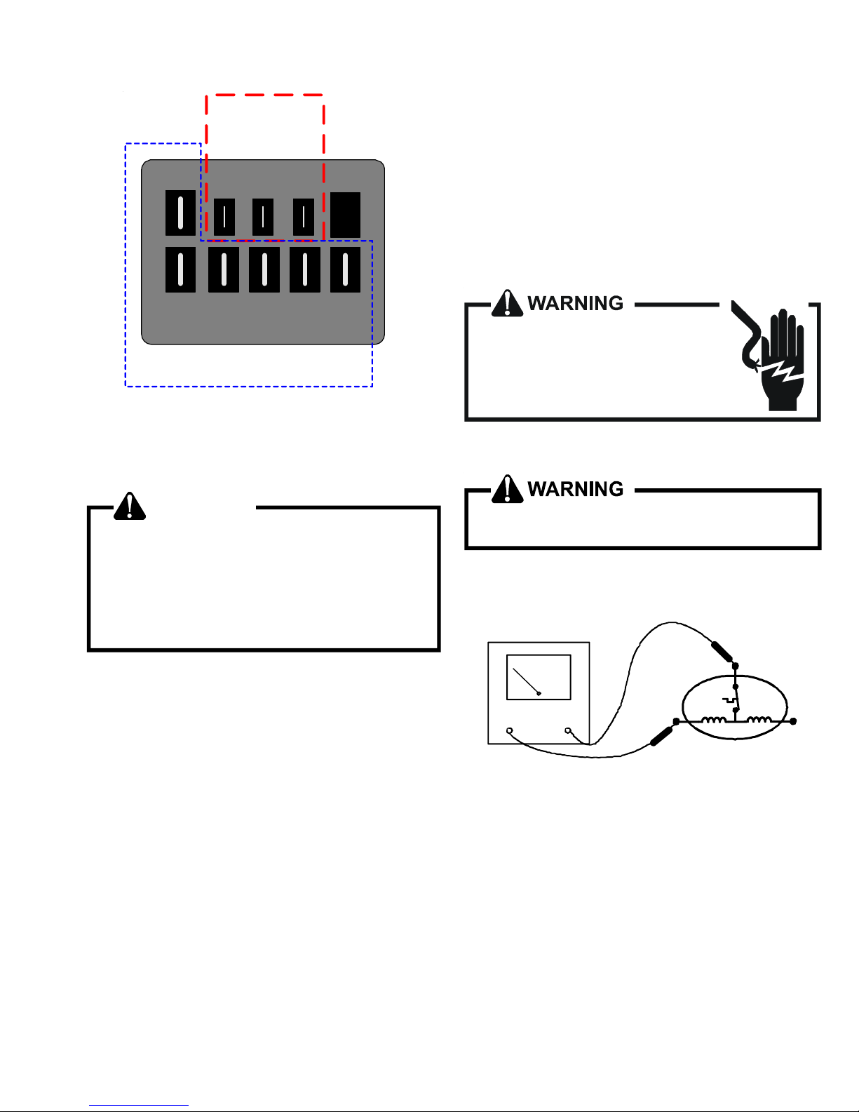
SERVICING
C
High Voltage
Connections
3/16"
LGN
S-17A RESISTANCE TEST
Each compressor is equipped with an internal overload.
The line break internal overload senses both motor amperage
and winding temperature. High motor temperature or amperage heats the disc causing it to open, breaking the common
circuit within the compressor on single phase units.
Heat generated within the compressor shell, usually due to
recycling of the motor, high amperage or insufficient gas to
cool the motor, is slow to dissipate. Allow at least three to four
hours for it to cool and reset, then retest.
123
4
5
Low Voltage Connections
1/4”
EEM MOTOR CONNECTIONS
S-17 CHECKING COMPRESSOR WINDINGS
WARNING
Hermetic compressor electrical terminal venting can
be dangerous. When insulating material which
supports a hermetic compressor or electrical terminal
suddenly disintegrates due to physical abuse or as a
result of an electrical short between the terminal and
the compressor housing, the terminal may be
expelle d, ve nting th e vap or a nd liq uid co nten ts of the
compressor housing and system.
If the compressor terminal PROTECTIVE COVER and
gasket (if required) are not properly in place and secured, there is a remote possibility if a terminal vents, that
the vaporous and liquid discharge can be ignited, spouting flames several feet, causing potentially severe or fatal
injury to anyone in its path.
This discharge can be ignited external to the compressor
if the terminal cover is not properly in place and if the
discharge impinges on a sufficient heat source.
Ignition of the discharge can also occur at the venting
terminal or inside the compressor, if there is sufficient
contaminant air present in the system and an electrical
arc occurs as the terminal vents.
Ignition cannot occur at the venting terminal without the
presence of contaminant air, and cannot occur externally
from the venting terminal without the presence of an
external ignition source.
Therefore, proper evacuation of a hermetic system is
essential at the time of manufacture and during servicing.
To reduce the possibility of external ignition, all open
flame, electrical power, and other heat sources should be
extinguished or turned off prior to servicing a system.
HIGH VOLTAGE!
Disconnect ALL power before servicing
or insta llin g th is un it. M ult iple powe r
sources may be present. Failure to do so
may cause property damage, personal injury
or death.
1. Remove the leads from the compressor terminals.
See warnings S-17 before removing compressor
terminal cover .
2. Using an ohmmeter, test continuity between terminals SR, C-R, and C-S, on single phase units or terminals T1,
T2 and T3, on 3 phase units.
C
OHMMETER
TESTING COMPRESSOR WINDINGS
If either winding does not test continuous, replace the
compressor.
NOTE: If an open compressor is indicated, allow ample time
for the internal overload to reset before replacing compressor.
S
COMP
R
S-17B GROUND TEST
If fuse, circuit breaker, ground fault protective device, etc.,
has tripped, this is a strong indication that an electrical
problem exists and must be found and corrected. The circuit
protective device rating must be checked, and its maximum
rating should coincide with that marked on the equipment
nameplate.
27

SERVICING
With the terminal protective cover in place, it is acceptable
to replace the fuse or reset the circuit breaker
ONLY to see if it was just a nuisance opening. If it opens
again,
DO NOT continue to reset.
WARNING
Disconnect ALL power before servicing.
ONE TIME
HIGH VOL TAGE!
Disconnect ALL power before servicing
or insta llin g this uni t. M ultip le po wer
sources may be present. Failure to do so
may cause property damage, personal injury
or death.
Disconnect all power to unit, making sure that all power
legs are open.
1. DO NOT remove protective terminal cover. Disconnect
the three leads going to the compressor terminals at the
nearest point to the compressor.
2. Identify the leads and using a Megger, Hi-Potential
Ground Tester, or other suitable instrument which puts
out a voltage between 300 and 1500 volts, check for a
ground separately between each of the three leads and
ground (such as an unpainted tube on the compressor).
Do not use a low voltage output instrument such as a voltohmmeter.
HI-POT
COMPRESSOR GROUND TEST
3. If a ground is indicated, then carefully remove the
compressor terminal protective cover and inspect for
loose leads or insulation breaks in the lead wires.
4. If no visual problems indicated, carefully remove the leads
at the compressor terminals.
WARNING
Damage can occur to the glass embedded terminals if
the leads are not properly removed. This can result in
terminal and hot oil discharging.
Carefully retest for ground, directly between compressor
terminals and ground.
5. If ground is indicated, replace the compressor.
S-17D OPERATION TEST
If the voltage, capacitor, overload and motor winding test fail
to show the cause for failure:
1. Remove unit wiring from disconnect switch and wire a
test cord to the disconnect switch.
NOTE: The wire size of the test cord must equal the line wire
size and the fuse must be of the proper size and type.
2. With the protective terminal cover in place, use the three
leads to the compressor terminals that were disconnected at the nearest point to the compressor and
connect the common, start and run clips to the respective
leads.
3. Connect good capacitors of the right MFD and voltage
rating into the circuit as shown.
4. With power ON, close the switch.
WARNING
Line Voltage now present.
A.If the compressor starts and continues to run, the cause
for failure is somewhere else in the system.
B.If the compressor fails to start - replace.
S-18 TESTING CRANKCASE HEATER (OP-
TIONAL ITEM)
Note: Not all compressors use crankcase heaters.
The crankcase heater must be energized a minimum of
twenty-four (24) hours before the compressor is operated.
Crankcase heaters are used to prevent migration or accumulation of refrigerant in the compressor crankcase during
the off cycles and prevents liquid slugging or oil pumping on
start up. On some models, the crankcase heater is controlled
by a crankcase heater thermostat that is wired in series with
the crankcase heater.
A crankcase heater will not prevent compressor damage
due to a floodback or over charge condition.
WARNING
Disconnect ALL power before servicing.
1. Disconnect the heater lead in wires.
2. Using an ohmmeter, check heater continuity - should test
continuous. If not, replace.
28

SERVICING
S-18A CHECKING CRANKCASE HEATER THER-
MOSTAT
Note: Not all models with crankcase heaters will have a
crankcase heater thermostat.
1. Install a thermocouple type temperature test lead on the
discharge line adjacent to the crankcase heater thermostat.
2. Check the temperature at which the control closes its
contacts by lowering the temperature of the control. The
crankcase heater thermostat should close at 67°F ± 5°F.
3. Check the temperature at which the control opens its
contacts by raising the temperature of the control. The
crankcase heater thermostat should open at 85°F ± 5°F.
4. If not as above, replace control.
S-21 CHECKING REVERSING VALVE AND SOLE-
NOID
Occasionally the reversing valve may stick in the heating or
cooling position or in the mid-position.
When stuck in the mid-position, part of the discharge gas
from the compressor is directed back to the suction side,
resulting in excessively high suction pressure. An increase
in the suction line temperature through the reversing valve
can also be measured. Check operation of the valve by
starting the system and switching the operation from COOLING to HEATING cycle.
If the valve fails to change its position, test the voltage (24V)
at the valve coil terminals, while the system is on the COOLING
cycle.
If no voltage is registered at the coil terminals, check the
operation of the thermostat and the continuity of the connecting wiring from the "O" terminal of the thermostat to the unit.
If voltage is registered at the coil, tap the valve body lightly
while switching the system from HEATING to COOLING, etc.
If this fails to cause the valve to switch positions, remove the
coil connector cap and test the continuity of the reversing
valve solenoid coil. If the coil does not test continuous replace it.
If the coil test continuous and 24 volts is present at the coil
terminals, the valve is inoperative - replace it.
5. Using VOM check for voltage across terminals "C & O".
Meter should read 24 volts.
6. Using VOM check for voltage across fan terminals DF1
and DF2 on the board. You should read line voltage (208230 VAC) indicating the relay is open in the defrost mode.
7. Using VOM check for voltage across "W2 & C" terminals
on the board. You should read 24 volts.
8. If not as above, replace control board.
9. Set thermostat to off position and disconnect power
before removing any jumpers or wires.
NOTE: Remove jumper across defrost thermostat before
returning system to service.
S-25 TESTING DEFROST THERMOSTAT
1. Install a thermocouple type temperature test lead on the
tube adjacent to the defrost control. Insulate the lead
point of contact.
2. Check the temperature at which the control closes its
contacts by lowering the temperature of the control. On
2 and 2.5 ton units, it should close at 34°F ± 5°F. On 3 thru
5 ton units, it should close at 31°F ± 3°F.
3. Check the temperature at which the control opens its
contacts by raising the temperature of the control. On 2
and 2.5 ton units, it should open at 60°F ± 5°F. On 3 thru
5 ton units, it should open at 75°F ± 6°F.
4. If not as above, replace control.
TROUBLESHOOTING
THE FOLLOWING INFORMATION IS FOR USE BY QUALIFIED SERVICE AGENCY ONLY: OTHERS SHOULD NOT
ATTEMPT TO SERVICE THIS EQUIPMENT.
Common Causes of Unsatisfactory Operation of Heat Pump
on the Heating Cycle.
INADEQUATE AIR VOLUME THROUGH INDOOR COIL
When a heat pump is in the heating cycle, the indoor coil is
functioning as a condenser. The return air filter must always
be clean, and sufficient air volume must pass through the
indoor coil to prevent excessive discharge pressure, and high
pressure cut out.
S-24 TESTING DEFROST CONTROL
To check the defrost control for proper sequencing, proceed
as follows: With power ON; unit not running.
1. Jumper defrost thermostat by placing a jumper wire
across the terminals "DFT" and "R" at defrost control
board.
2. Connect jumper across test pins on defrost control board.
3. Set thermostat to call for heating. System should go into
defrost within 21 seconds.
4. Immediately remove jumper from test pins.
OUTSIDE AIR INTO RETURN DUCT
Do not introduce cold outside air into the return duct of a heat
pump installation. For units with 2-speed motors, do not
allow air entering the indoor coil to drop below 65° F. Air below
this temperature will cause low discharge pressure, thus low
suction pressure, and excessive defrost cycling resulting in
low heating output. It may also cause false defrosting.
29

SERVICING
U
NDERCHARGE
An undercharged heat pump on the heating cycle will cause
low discharge pressure resulting in low suction pressure and
frost accumulation on the outdoor coil.
POOR “TERMINATING” SENSOR CONTACT
The unit’s defrost terminating sensor must make good
thermal contact with the outdoor coil tubing. Poor contact
may not terminate the unit’s defrost cycle quickly enough to
prevent the unit from cutting out on high discharge pressure.
MALFUNCTIONING REVERSING VALVE - THIS MAY BE DUE
:
TO
1. Solenoid not energized - In order to determine if the
solenoid is energized, touch the nut that holds the
solenoid cover in place with a screwdriver. If the nut
magnetically holds the screwdriver, the solenoid is
energized and the unit is in the cooling cycle.
2. No voltage at unit’s solenoid - Check unit voltage. If
no voltage, check wiring circuit.
3. Valve will not shift:
a. Undercharged - check for leaks;
b. Valve Body Damaged - Replace valve;
c. Unit Properly Charged - If it is on the heating cycle,
raise the discharge pressure by restricting airflow
through the indoor coil. If the valve does not shift, tap
it lightly on both ends with a screwdriver handle. DO
NOT TAP THE VALVE BODY. If the unit is on the
cooling cycle, raise the discharge pressure by restricting airflow through the outdoor coil. If the valve
does not shift after the above attempts, cut the unit off
and wait until the discharge and suction pressure
equalize, and repeat above steps. If the valve does not
shift, replace it.
S-100 REFRIGERATION REPAIR PRACTICE
DANGER
Always remove the refrigerant charge in a proper
manner before applying heat to the system.
When repairing the refrigeration system:
WARNING
Disconnect ALL power before servicing.
1. Never open a system that is under vacuum. Air and
moisture will be drawn in.
2. Plug or cap all openings.
3. Remove all burrs and clean the brazing surfaces of the
tubing with sand cloth or paper. Brazing materials do not
flow well on oxidized or oily surfaces.
4. Clean the inside of all new tubing to remove oils and pipe
chips.
5. When brazing, sweep the tubing with dry nitrogen to
prevent the formation of oxides on the inside surfaces.
6. Complete any repair by replacing the liquid line drier in the
system, evacuate and charge.
BRAZING MATERIALS
Copper to Copper Joints - Sil-Fos used without flux (alloy
of 15% silver, 80% copper, and 5% phosphorous). Recommended heat 1400°F.
Copper to Steel Joints - Silver Solder used without a flux
(alloy of 30% silver, 38% copper, 32% zinc). Recommended
heat - 1200°F.
S-50 CHECKING HEATER LIMIT CONTROL(S)
(OPTIONAL ELECTRIC HEATERS)
Each individual heater element is protected with an automatic
rest limit control connected in series with each element to
prevent overheating of components in case of low airflow.
This limit control will open its circuit at approximately 150°F.
to 160°F and close at approximately 110°F.
WARNING
Disconnect ALL power before servicing.
1. Remove the wiring from the control terminals.
2. Using an ohmmeter test for continuity across the normally closed contacts. No reading indicates the control
is open - replace if necessary. Make sure the limits are
cool before testing.
IF FOUND OPEN - REPLACE - DO NOT WIRE AROUND.
30
S-101 LEAK TESTING
(NITROGEN OR NITROGEN-TRACED)
WARNING
To avoid the risk of fire or explosion, never use
oxygen, high pressure air or flammable gases for leak
testing of a refrigeration system.
 Loading...