

Daikin BS4Q14AV1, BS10Q14AV1, BS6Q14AV1, BS12Q14AV1, BS8Q14AV1 Installation manuals
...
INSTALLATION MANUAL
SYSTEM Air Conditioners
English
Deutsch
MODELS
〈BS unit〉
BS4Q14AV1 BS10Q14AV1
BS6Q14AV1 BS12Q14AV1
BS8Q14AV1 BS16Q14AV1
READ THESE INSTRUCTIONS CAREFULLY BEFORE INSTALLATION.
KEEP THIS MANUAL IN A HANDY PLACE FOR FUTURE REFERENCE.
LESEN SIE DIESE ANWEISUNGEN VOR DER INSTALLATION SORGFÄLTIG DURCH.
BEWAHREN SIE DIESE ANLEITUNG FÜR SPÄTERE BEZUGNAHME GRIFFBEREIT AUF.
LIRE SOIGNEUSEMENT CES INSTRUCTIONS AVANT L’INSTALLATION.
CONSERVER CE MANUEL A PORTEE DE MAIN POUR REFERENCE ULTERIEURE.
LEA CUIDADOSAMENTE ESTAS INSTRUCCIONES ANTES DE INSTALAR.
GUARDE ESTE MANUAL EN UN LUGAR A MANO PARA LEER EN CASO DE TENER
ALGUNA DUDA.
PRIMA DELL’INSTALLAZIONE LEGGERE ATTENTAMENTE QUESTE ISTRUZIONI.
TENERE QUESTO MANUALE A PORTATA DI MANO PER RIFERIMENTI FUTURI.
Français
Español
Italiano
Ελληνικά
Nederlands
Português
Русский
ΔΙΑΒΑΣΤΕ ΠΡΟΣΕΚΤΙΚΑ ΑΥΤΕΣ ΤΙΣ ΟΔΗΓΙΕΣ ΠΡΙΝ ΑΠΟ ΤΗΝ ΕΓΚΑΤΑΣΤΑΣΗ ΕΧΕΤΕ
ΑΥΤΟ ΤΟ ΕΓΧΕΙΡΙΔΙΟ ΕΥΚΑΙΡΟ ΓΙΑ ΝΑ ΤΟ ΣΥΜΒΟΥΛΕΥΕΣΤΕ ΣΤΟ ΜΕΛΛΟΝ.
LEES DEZE INSTRUCTIES ZORGVULDIG DOOR VOOR INSTALLATIE. BEWAAR DEZE
HANDLEINDING WAAR U HEM KUNT TERUGVINDEN VOOR LATERE NASLAG.
LEIA COM ATENÇÃO ESTAS INSTRUÇÕES ANTES DE REALIZAR A INSTALAÇÃO.
MANTENHA ESTE MANUAL AO SEU ALCANCE PARA FUTURAS CONSULTAS.
ПЕРЕД НАЧАЛОМ МОНТАЖА ВНИМАТЕЛЬНО ОЗНАКОМЬТЕСЬ С ДАННЫМИ
ИНСТРУКЦЯМИ. СОХРАНИТЕ ДАННОЕ РУКОВОДСТВО В МЕСТЕ, УДОБНОМ ДЛЯ
ОБРАЩЕНИЯ В БУДУЩЕМ.
MONTAJDAN ÖNCE BU TALİMATLARI DİKKATLİ BİR BİÇİMDE OKUYUN.
GELECEKTE BAŞVURMAK ÜZERE BU ELKİTABINI KORAY ULAŞABİLECEĞİNİZ BİR
YERDE MUHAFAZA EDİN.
Türkçe
BS4Q14AV1
BS6Q14AV1
BS8Q14AV1
BS10Q14AV1
BS12Q14AV1
BS16Q14AV1
VRVIV SYSTEM Air Conditioners
Installation manual
CONTENTS
1. SAFETY PRECAUTIONS ...............................................................................................1
2. BEFORE INSTALLATION ...............................................................................................3
3. SELECTING INSTALLATION SITE .................................................................................5
4. PREPARATIONS BEFORE INSTALLATION ...................................................................6
5. BS UNIT INSTALLATION ................................................................................................6
6. REFRIGERANT PIPING WORK .....................................................................................7
7. DRAIN PIPING WORK .................................................................................................12
8. ELECTRIC WIRING WORK ..........................................................................................14
9. INITIAL SETTING .........................................................................................................20
10. ADDING AN ADDITIONAL CHARGE OF REFRIGERANT ..........................................21
11. CHECK OPERATION AND TEST OPERATION ...........................................................21
The original instructions are written in English. All other languages are translations of the original instructions.
1. SAFETY PRECAUTIONS
Be sure to follow this “SAFETY PRECAUTIONS”.
This product comes under the term “appliances not accessible to the general public”.
This is a class A product. In a domestic environment this product may cause radio interference in which
case the user may be required to take adequate measures.
This manual classies the precautions into WARNINGS and CAUTIONS.
Be sure to follow all the precautions below: They are all important for ensuring safety.
WARNING .........
CAUTION .........
WARNING
• Ask your local dealer or qualied personnel to carry out installation work.
Improper installation may result in water leakage, electric shocks or a re.
• Perform installation work in accordance with this installation manual.
Improper installation may result in water leakage, electric shocks or a re.
• Consult your local dealer regarding what to do in case of refrigerant leakage.
When the air conditioner is installed in a small room, it is necessary to take proper measures so that the
amount of any leaked refrigerant does not exceed the concentration limit in the event of a leakage.
Otherwise, this may lead to an accident due to oxygen deciency.
• Be sure to use only the specied parts and accessories for installation work.
Failure to use the specied parts may result in the air conditioner falling down, water leakage, electric
shocks, a re, etc.
• Install the air conditioner on a foundation that can withstand its mass.
Insufcient strength may result in the air conditioner falling down and causing injury.
In addition, it may lead to vibration of indoor units and cause unpleasant chattering noise.
• Carry out the specied installation work in consideration of strong winds, typhoons, or earthquakes.
Improper installation may result in an accident such as air conditioner falling.
Indicates a potentially hazardous situation which, if not avoided, could result in death
or serious injury.
Indicates a potentially hazardous situation which, if not avoided, may result in minor
or moderate injury.
It may also be used to alert against unsafe practices.
English 1
• Make certain that all electrical work is carried out by qualied personnel according to the applicable leg-
islation (note 1) and this installation manual, using a separate circuit.
In addition, even if the wiring is short, make sure to use a wiring that has sufcient length and never
connect additional wiring to make the length sufcient.
Insufcient capacity of the power supply circuit or improper electrical construction may lead to electric
shocks or a re.
(note 1) applicable legislation means “All international, national and local directives, laws, regulations
and/or codes which are relevant and applicable for a certain product or domain”.
• Earth the air conditioner.
Do not connect the earth wiring to gas or water piping, lightning conductor or telephone earth wiring.
Incomplete earthing may cause electric shocks or a re.
A high surge current from lightning or other sources may cause damage to the air conditioner.
• Be sure to install an earth leakage circuit breaker.
Failure to do so may cause electric shocks and a re.
• Disconnect the power supply before touching the electric components.
If you touch the live part, you may get an electric shocks.
• Make sure that all wiring is secure, using the specied wiring and ensuring that external forces do not act
on the terminal connections or wiring.
Incomplete connection or xing may cause an overheat or a re.
• Wiring for power supply and between the indoor and outdoor units must be properly laid and formed, and
the control box cover must be rmly fastened so that the wiring may not push up the structural parts such
as the cover.
If the cover is improperly fastened, it may cause electric shock or re.
• If refrigerant gas leaks during installation work, ventilate the area immediately.
Toxic gas may be produced if refrigerant gas comes into contact with a re.
• After completing the installation work, check to make sure that there is no leakage of refrigerant gas.
Toxic gas may be produced if refrigerant gas leaks into the room and comes into contact with a source of
a re, such as a fan heater, stove or cooker.
• Never directly touch any accidental leaking refrigerant. This could result in severe wounds caused by
frostbite.
CAUTION
Install drain piping according to this installation manual to ensure good drainage, and insulate the piping
•
to prevent condensation.
Improper drain piping may cause water leakage, make the furniture get wet.
•
Install the BS units, power supply wiring, remote controller wiring and transmission wiring at least 1 m
away from televisions or radios to prevent image interference or noise.
(Depending on the radio waves, a distance of 1 m may not be sufcient to eliminate the noise.)
• Install the BS unit as far as possible from uorescent lamps.
If a wireless remote controller kit is installed, the transmission distance may be shorter in a room where
an electronic lighting type (inverter or rapid start type) uorescent lamp is installed.
• Make sure to provide for adequate measures in order to prevent that the outdoor unit be used as a shel-
ter by small animals.
Small animals making contact with electrical parts can cause malfunctions, smoke or re. Please instruct
the customer to keep the area around the unit clean.
• Do not install the air conditioner in places such as the following:
1. The outside building, rain water permeates in BS unit and it becomes a cause of an electric shock.
2. Where there is mist of oil, oil spray or vapour for example a kitchen.
Resin parts may deteriorate, and cause them to fall out or water to leak.
3. Where corrosive gas, such as sulfurous acid gas, is produced.
Corrosion of copper pipings or brazed parts may cause the refrigerant to leak.
4. Where there is machinery which emits electromagnetic waves.
Electromagnetic waves may disturb the control system, and cause malfunction of the equipment.
2 English
5. Where ammable gases may leak, where carbon bre or ignitable dust is suspended in the air or
where volatile ammables, such as thinner or gasoline, are handled.
If the gas should leak and remained around the air conditioner, it may cause ignition.
6. Do not use in areas where the air is salty, such as along seacoasts, in factories or other areas with
signicant voltage uctuations, or in automobiles and watercraft.
Doing so could result in a malfunction.
7. Where a wind may ow, the surface of BS unit body dews, and it becomes a cause of a leak.
• The BS unit is not intended for use in a potentially explosive atmosphere.
2. BEFORE INSTALLATION
2-1 Precautions
• Be sure to verify in advance that the refrigerant used in installation work is R410A.
The unit will not operate correctly with a different type of refrigerant.
• When moving the unit during or after unpacking, hold it using the 4 hanging brackets and avoid
subjecting other parts, particularly refrigerant pipes and the control box, to force.
• For more information about installation of outdoor and indoor units, refer to the installation manual
that came with each unit.
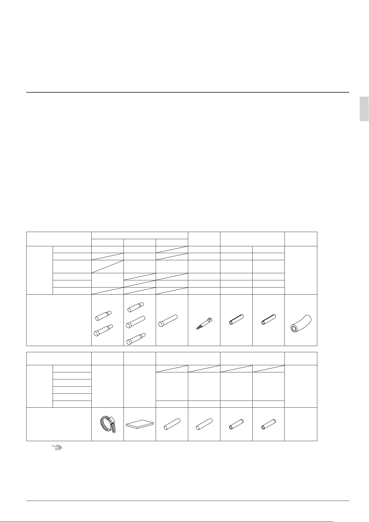
2-2 Accessories
• Verify that the following accessories have been included in the packaging.
Important
Do not throw away any accessories that may be needed in installation work until installation is complete.
Quantity
Quantity
Name
BS4Q14AV1 1 pc. (f19.1) 1 pc. (f15.9) 23 pcs. 4 pcs. 4 pcs.
BS6Q14AV1 1 pc. (f22.2) 32 pcs. 6 pcs. 6 pcs.
BS8Q14AV1
BS10Q14AV1
BS12Q14AV1 1 pc. (f19.1) 57 pcs. 12 pcs. 12 pcs.
BS16Q14AV1 74 pcs. 16 pcs. 16 pcs.
Shape
Name
BS4Q14AV1
BS6Q14AV1
BS8Q14AV1
BS10Q14AV1
BS12Q14AV1
BS16Q14AV1 3 pcs. 3 pcs. 3 pcs. 3 pcs.
Shape
Suction gas HP/LP gas Liquid
1 pc. (f34.9)
(1)-1 (1)-2 (1)-3 (2) (3)-1 (3)-2
Metal clamp
Accessory pipes (1)
2 pc.
(f22.2, f28.6)
f19.1
f34.9
(5)
1 pc. 1 sheet 1 copy
Sealing
material (6)
1 pc. (f15.9) 40 pcs. 8 pcs. 8 pcs.
f15.9
f22.2
f28.6
Stopper pipes (7)
1 pc. 1 pc. 1 pc. 1 pc.
(7)-1 (7)-2 (8)-1 (8)-2
ϕ9.5 ϕ15.9
Clamps (2) Insulation tube (3)
49 pcs. 10 pcs. 10 pcs.
f15.9
f19.1
(Thin) (Thick)
Insulation tube for stopper
pipes (8)
(Thin) (Thick)
Drain hoses
(4)
1 pc.
Documenta-
tion
Installation
Manual
NOTES
• You will need a reducing joint (to be supplied in the eld) if the diameter of the pipe on site as described
in the outdoor unit’s installation manual or equipment design materials does not match the diameter of
the connection pipe on the outdoor side of the BS unit.
• Thermal insulation for connection pipes on the outdoor unit side must be supplied in the eld.
English 3

2-3 Combination
• This BS unit is only for systems for Models REYQ-T.
It cannot be connected to systems for Models REYQ-P.
• For series of applicable indoor units, refer to the catalog or other literature.
• Select the BS unit to t the total capacity (sum of unit’s capacity) of the indoor units to be connected
downstream, refer to the Table 1. About indoor unit’s capacity, refer to the Table 2.
Table 1
Model Total capacity of all downstream indoor units
BS4Q14AV1 A ≤ 400 (*)
BS6Q14AV1 A ≤ 600 (*)
BS8Q14AV1
BS10Q14AV1
BS12Q14AV1
BS16Q14AV1
* The total capacity and number of indoor units connectable to each branch connector are up to 140
and 5, respectively.
* When the total capacity of indoor units to be connected downstream is larger than 140 (MAX.
250), use a junction pipe kit (KHRP26A250T, sold separately) to join two connections downstream
from the BS unit.
Table 2
Capacity expressed as indoor unit’s model No. 20 25 32 40 50 63 80 100 125
Indoor unit’s capacity (for use in computation) 20 25 31.25 40 50 62.5 80 100 125
* About indoor unit’s capacity for HRV type (VKM), refer to the Engineering data book.
<Example selection>
In case of the BS unit with connect a FXCQ32M and a FXSQ40M.
Total capacity = 31.25+40 = 71.25
A ≤ 750 (*)
2-4 Checklist
Exercise particular care concerning the following items during installation work and check again after
installation is complete:
Post-installation checklist
Checklist If defective Check here.
Has the BS unit been installed securely? The unit may fall, vibrate, or operate noisily.
Did you conduct a gas leak inspection? The unit may fail to heat or cool as designed.
Was the unit fully insulated? (Refrigerant pipes and drain pipes) The unit may leak water.
Does water ow smoothly from the drain? The unit may leak water.
Is the supply voltage the same as the voltage indicated on the
label?
Are there any wiring mistakes or erroneous wiring or erroneous
pipe connections?
Has the unit been earthed?
Is the thickness of the electrical wiring the same as described in
the specications?
Delivery checklist
Checklist Check here.
Has a cover been installed on the control box?
Did you give the customer the installation manual?
The unit may fail to operate or burn up.
The unit may fail to operate, burn up, or produce
abnormal noise.
The unit may pose a hazard in the event of a
short-circuit.
The unit may fail to operate or burn up.
4 English
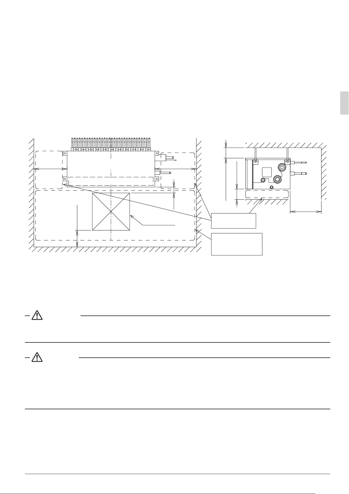
3. SELECTING INSTALLATION SITE
Consider the following requirements when choosing the installation location and obtain the customer’s consent:
• The location must be able to withstand the weight of the BS unit.
• The location must allow reliable draining.
• The location must allow inspection holes to be installed on the control box side. (A separate opening is
necessary when lowering the product.)
• There must be adequate space in which to perform installation and service work (Refer to Fig. 1).
• The length of pipe to the indoor unit and outdoor unit must be less than or equal to the permissible pipe
length (as listed in the installation manual that came with the outdoor unit).
• The sound of refrigerant being pumped through the pipes must not be a problem. (Never install above the
ceiling of an occupied room.)
300 or
more
450 (*2)
BS unit
Top of unit
Control box
500 or more (*1)
Inspection hole
450 × 450
70
(*3)
or more
100
or more
100
Drain pan
Maintenance space
Control box and
motorized valve coil
Maintenance space
Indoor unit
side pipe
(*1)
Unit: mm
Fig. 1
(*1) Leave enough space to connect the site pipes.
(*2) This space is needed to place the top plate when performing service on the motor operated valve coil.
(*3) This space is needed to remove the top plate when performing service on the motor operated valve
coil.
WARNING
Securely install the unit at a location that is capable of withstanding its weight.
Inadequate strength may cause the indoor unit to fall, resulting in bodily injury.
CAUTION
• Leave enough space to perform maintenance on the drain pan and control box.
• To prevent video and audio interference, install the BS unit as well as associated power wiring and signal
transmission lines at least 1 m away from TVs and radios.
However, depending on the reception, interference may result even if a minimum distance of 1 m is maintained.
English 5
4. PREPARATIONS BEFORE INSTALLATION
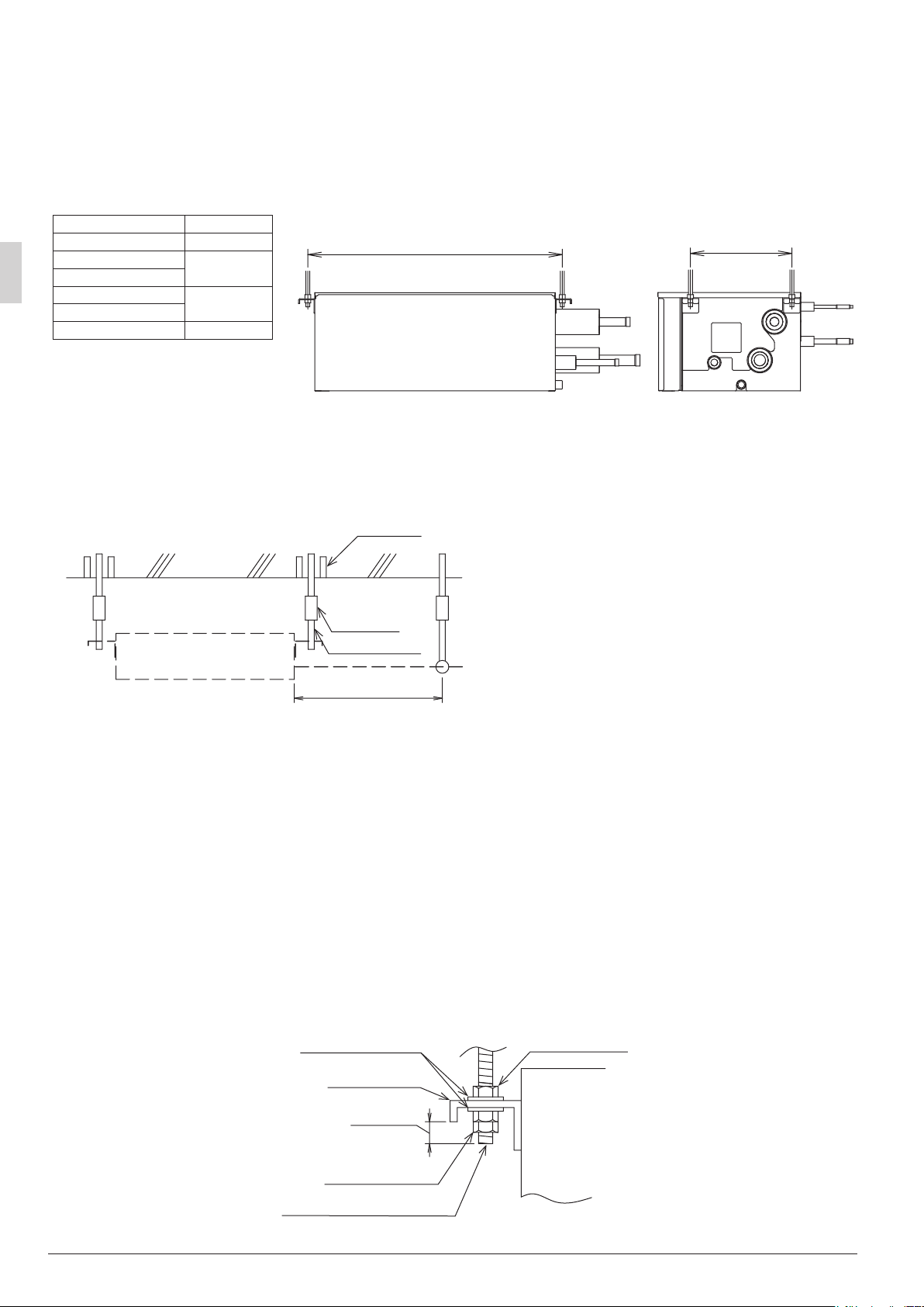
Install suspension bolts and hanging brackets as illustrated in the diagram below.
• Use a suspension bolt size of M8 to M10.
• Use mold-in inserts and embedded foundation bolts for new installations or hole-in anchor bolts or similar
hardware for existing installations, taking care to install in a manner that can withstand the unit’s weight.
Unit: mm
BS unit A
BS4Q14AV1 415
BS6Q14AV1
BS8Q14AV1
BS10Q14AV1
BS12Q14AV1
BS16Q14AV1 1105
625
865
A 308
<Suspension bolt spacing>
• Use the hanging brackets to support the connection pipes on both the front and back of the unit within
1 m of the unit’s side.
Placing an excessive amount of weight on the BS unit’s hanging brackets may cause the unit to fall,
resulting in bodily injury.
Slab
Unit
Anchor bolt
Long nut or
turnbuckle
Suspension bolt
Within 1 m
Connection
pipe
All the above parts must be supplied in the eld
<Example installation>
5. BS UNIT INSTALLATION
Use only accessories and parts that conform to the designated specications when installing the unit.
1. Position the BS unit and secure it temporarily in place.
Attach the hanging brackets to the suspension bolts as per the instructions in the gure to the right.
Be sure to afx nuts (M8 or M10, 3 pieces in 4 locations) and washers (for M8, outside diameter of 24 to
28 mm or for M10, outside diameter of 30 to 34 mm: 2 pieces in 4 locations) (to be supplied in the eld)
from both the top and bottom of the hanging brackets on both sides of the unit to secure it in place.
2. Adjust the height of the unit as desired.
3. Using a level, verify that the unit has been installed in a level orientation.
(The unit should be either level or within 1° of slope toward the drain socket.)
Washer (Field supply)
Hanging bracket
10 - 15 mm
Nut (double nut)
(Field supply)
Nut (Field supply)
BS unit
Suspension bolt (Field supply)
6 English
 Loading...