


Installation manual
Communication box
BRR9B1V1

Table of contents
Table of contents
1 About the documentation 3
1.1 About this document ...................................................................................................................................................... 3
2 General safety precautions 4
2.1 About the documentation .............................................................................................................................................. 4
2.1.1 Meaning of warnings and symbols ................................................................................................................ 4
2.2 For the installer............................................................................................................................................................... 5
2.2.1 General ........................................................................................................................................................... 5
2.2.2 Installation site ............................................................................................................................................... 6
2.2.3 Electrical ......................................................................................................................................................... 7
3 Specific installer safety instructions 9
4 About the box 10
4.1 Communication box........................................................................................................................................................ 10
4.1.1 To remove the accessories from the communication box ............................................................................ 10
5 About the communication box 11
5.1 Identification ................................................................................................................................................................... 11
5.1.1 Identification label: Communication box ....................................................................................................... 11
6 Unit installation 12
6.1 Preparing the installation site......................................................................................................................................... 12
6.1.1 Installation site requirements of the communication box ............................................................................ 12
6.2 Opening and closing the unit.......................................................................................................................................... 12
6.2.1 To open the communication box ................................................................................................................... 12
6.2.2 To close the communication box ................................................................................................................... 13
6.3 Installing the communication box .................................................................................................................................. 13
6.3.1 Precautions when installing the communication box ................................................................................... 13
6.3.2 To install the communication box .................................................................................................................. 13
7 Electrical installation 14
7.1 General overview of the field wiring .............................................................................................................................. 14
7.2 Field wiring: Overview .................................................................................................................................................... 15
7.3 Guidelines when connecting the electrical wiring ......................................................................................................... 16
7.4 Specifications of standard wiring components .............................................................................................................. 16
7.5 To connect the electrical wiring on the communication box ........................................................................................ 17
7.6 To connect the transmission wiring ............................................................................................................................... 18
7.6.1 Between communication box and outdoor unit ........................................................................................... 18
7.6.2 Between communication box and monitoring system.................................................................................. 18
7.7 To fix the wiring cables with cable ties........................................................................................................................... 19
8 Configuration 20
8.1 About the PCBs ............................................................................................................................................................... 20
8.2 Setting the addresses of outdoor units and indoor units .............................................................................................. 20
8.3 To set the addresses of the outdoor unit and capacity up unit..................................................................................... 21
8.4 To set the addresses of the indoor units........................................................................................................................ 22
8.5 Configuring the communication box.............................................................................................................................. 22
8.5.1 To configure the communication box PCB for the indoor units.................................................................... 23
8.5.2 To configure the communication box PCB for the outdoor unit and capacity up unit................................. 24
9 Commissioning 28
10 Troubleshooting 29
10.1 Troubleshooting for PCB for indoor unit communication ............................................................................................. 29
10.2 Troubleshooting for PCB for outdoor unit and capacity up unit communication......................................................... 29
11 Technical data 33
11.1 Wiring diagram: Communication box............................................................................................................................. 33
12 Glossary 34
Installation manual
2
BRR9B1V1
Communication box
4P617761-1B – 2020.10

1 About the documentation
1.1 About this document
Target audience
Authorised installers
WARNING
Make sure installation, servicing, maintenance, repair and applied materials follow
the instructions from Daikin and, in addition, comply with applicable legislation and
are performed by qualified persons only. In Europe and areas where IEC standards
apply, EN/IEC 60335-2-40 is the applicable standard.
Documentation set
This document is part of a documentation set. The complete set consists of:
▪ Installation manual:
- Installation instructions, configuration,…
1 | About the documentation
- Format: Paper (supplied in the kit) + digital files on http://
www.daikineurope.com/support-and-manuals/product-information/
Latest revisions of the supplied documentation may be available on the regional
Daikin website or via your dealer.
The original documentation is written in English. All other languages are
translations.
Technical engineering data
▪ A subset of the latest technical data is available on the regional Daikin website
(publicly accessible).
▪ The full set of latest technical data is available on the Daikin Business Portal
(authentication required).
BRR9B1V1
Communication box
4P617761-1B – 2020.10
Installation manual
3
2 | General safety precautions
2 General safety precautions
2.1 About the documentation
▪ The original documentation is written in English. All other languages are
translations.
▪ The precautions described in this document cover very important topics, follow
them carefully.
▪ The installation of the system, and all activities described in the installation
manual and in the installer reference guide MUST be performed by an authorised
installer.
2.1.1 Meaning of warnings and symbols
DANGER
Indicates a situation that results in death or serious injury.
DANGER: RISK OF ELECTROCUTION
Indicates a situation that could result in electrocution.
DANGER: RISK OF BURNING/SCALDING
Indicates a situation that could result in burning/scalding because of extreme hot or
cold temperatures.
DANGER: RISK OF EXPLOSION
Indicates a situation that could result in explosion.
WARNING
Indicates a situation that could result in death or serious injury.
WARNING: FLAMMABLE MATERIAL
CAUTION
Indicates a situation that could result in minor or moderate injury.
Installation manual
4
NOTICE
Indicates a situation that could result in equipment or property damage.
INFORMATION
Indicates useful tips or additional information.
Symbols used on the unit:
BRR9B1V1
Communication box
4P617761-1B – 2020.10
Symbol Explanation
Before installation, read the installation and operation
manual, and the wiring instruction sheet.
Before performing maintenance and service tasks, read the
service manual.
For more information, see the installer and user reference
guide.
The unit contains rotating parts. Be careful when servicing or
inspecting the unit.
Symbols used in the documentation:
Symbol Explanation
Indicates a figure title or a reference to it.
Example: " 1–3 Figure title" means "Figure 3 in chapter 1".
Indicates a table title or a reference to it.
Example: " 1–3 Table title" means "Table 3 in chapter 1".
2 | General safety precautions
2.2 For the installer
2.2.1 General
If you are NOT sure how to install or operate the unit, contact your dealer.
DANGER: RISK OF BURNING/SCALDING
▪ Do NOT touch the refrigerant piping, water piping or internal parts during and
immediately after operation. It could be too hot or too cold. Give it time to return
to normal temperature. If you must touch it, wear protective gloves.
▪ Do NOT touch any accidental leaking refrigerant.
WARNING
Improper installation or attachment of equipment or accessories could result in
electrical shock, short-circuit, leaks, fire or other damage to the equipment. Only use
accessories, optional equipment and spare parts made or approved by Daikin.
WARNING
Make sure installation, testing and applied materials comply with applicable
legislation (on top of the instructions described in the Daikin documentation).
BRR9B1V1
Communication box
4P617761-1B – 2020.10
CAUTION
Wear adequate personal protective equipment (protective gloves, safety glasses,…)
when installing, maintaining or servicing the system.
WARNING
Tear apart and throw away plastic packaging bags so that nobody, especially
children, can play with them. Possible risk: suffocation.
Installation manual
5
2 | General safety precautions
In accordance with the applicable legislation, it might be necessary to provide a
logbook with the product containing at least: information on maintenance, repair
work, results of tests, stand-by periods,…
WARNING
Provide adequate measures to prevent that the unit can be used as a shelter by small
animals. Small animals that make contact with electrical parts can cause
malfunctions, smoke or fire.
CAUTION
Do NOT touch the air inlet or aluminium fins of the unit.
CAUTION
▪ Do NOT place any objects or equipment on top of the unit.
▪ Do NOT sit, climb or stand on the unit.
NOTICE
Works executed on the outdoor unit are best done under dry weather conditions to
avoid water ingress.
2.2.2 Installation site
Also, at least, following information MUST be provided at an accessible place at the
product:
▪ Instructions for shutting down the system in case of an emergency
▪ Name and address of fire department, police and hospital
▪ Name, address and day and night telephone numbers for obtaining service
In Europe, EN378 provides the necessary guidance for this logbook.
▪ Provide sufficient space around the unit for servicing and air circulation.
▪ Make sure the installation site withstands the weight and vibration of the unit.
▪ Make sure the area is well ventilated. Do NOT block any ventilation openings.
▪ Make sure the unit is level.
Do NOT install the unit in the following places:
▪ In potentially explosive atmospheres.
▪ In places where there is machinery that emits electromagnetic waves.
Electromagnetic waves may disturb the control system, and cause malfunction of
the equipment.
▪ In places where there is a risk of fire due to the leakage of flammable gases
(example: thinner or gasoline), carbon fibre, ignitable dust.
Installation manual
6
▪ In places where corrosive gas (example: sulphurous acid gas) is produced.
Corrosion of copper pipes or soldered parts may cause the refrigerant to leak.
BRR9B1V1
Communication box
4P617761-1B – 2020.10
2.2.3 Electrical
2 | General safety precautions
DANGER: RISK OF ELECTROCUTION
▪ Turn OFF all power supply before removing the switch box cover, connecting
electrical wiring or touching electrical parts.
▪ Disconnect the power supply for more than 10minutes, and measure the voltage
at the terminals of main circuit capacitors or electrical components before
servicing. The voltage MUST be less than 50VDC before you can touch electrical
components. For the location of the terminals, see the wiring diagram.
▪ Do NOT touch electrical components with wet hands.
▪ Do NOT leave the unit unattended when the service cover is removed.
WARNING
If NOT factory installed, a main switch or other means for disconnection, having a
contact separation in all poles providing full disconnection under overvoltage
categoryIII condition, MUST be installed in the fixed wiring.
WARNING
▪ ONLY use copper wires.
▪ Make sure the field wiring complies with the applicable legislation.
▪ All field wiring MUST be performed in accordance with the wiring diagram
supplied with the product.
▪ NEVER squeeze bundled cables and make sure they do NOT come in contact with
the piping and sharp edges. Make sure no external pressure is applied to the
terminal connections.
▪ Make sure to install earth wiring. Do NOT earth the unit to a utility pipe, surge
absorber, or telephone earth. Incomplete earth may cause electrical shock.
▪ Make sure to use a dedicated power circuit. NEVER use a power supply shared by
another appliance.
▪ Make sure to install the required fuses or circuit breakers.
▪ Make sure to install an earth leakage protector. Failure to do so may cause
electrical shock or fire.
▪ When installing the earth leakage protector, make sure it is compatible with the
inverter (resistant to high frequency electric noise) to avoid unnecessary opening
of the earth leakage protector.
BRR9B1V1
Communication box
4P617761-1B – 2020.10
CAUTION
▪ When connecting the power supply: connect the earth cable first, before making
the current-carrying connections.
▪ When disconnecting the power supply: disconnect the current-carrying cables
first, before separating the earth connection.
▪ The length of the conductors between the power supply stress relief and the
terminal block itself must be as such that the current-carrying wires are tautened
before the earth wire is in case the power supply is pulled loose from the stress
relief.
Installation manual
7
2 | General safety precautions
NOTICE
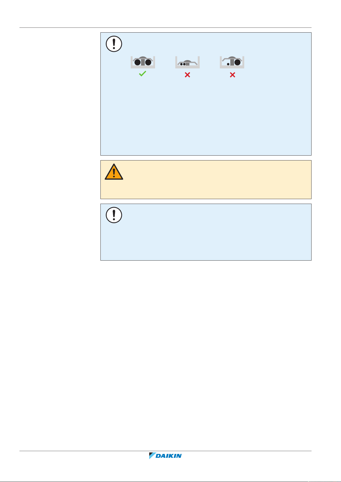
Precautions when laying power wiring:
▪ Do NOT connect wiring of different thicknesses to the power terminal block (slack
in the power wiring may cause abnormal heat).
▪ When connecting wiring which is the same thickness, do as shown in the figure
above.
▪ For wiring, use the designated power wire and connect firmly, then secure to
prevent outside pressure being exerted on the terminal board.
▪ Use an appropriate screwdriver for tightening the terminal screws. A screwdriver
with a small head will damage the head and make proper tightening impossible.
▪ Over-tightening the terminal screws may break them.
WARNING
▪ After finishing the electrical work, confirm that each electrical component and
terminal inside the electrical components box is connected securely.
▪ Make sure all covers are closed before starting up the unit.
NOTICE
Only applicable if the power supply is three‑phase, and the compressor has an ON/
OFF starting method.
If there exists the possibility of reversed phase after a momentary black out and the
power goes on and off while the product is operating, attach a reversed phase
protection circuit locally. Running the product in reversed phase can break the
compressor and other parts.
Installation manual
8
BRR9B1V1
Communication box
4P617761-1B – 2020.10
3 | Specific installer safety instructions
3 Specific installer safety instructions
Always observe the following safety instructions and regulations.
WARNING
Installation shall be done by an installer, the choice of materials and installation shall
comply with the applicable legislation. In Europe, EN378 is the applicable standard.
WARNING
Provide adequate measures to prevent that the unit can be used as a shelter by small
animals. Small animals that make contact with electrical parts can cause
malfunctions, smoke or fire.
WARNING
▪ Make sure the electrical wiring does NOT obstruct correct reattachment of the
communication box cover. Incorrect reattachment of the communication box
cover might result in electrical shocks, fire, or terminal overheating.
▪ Do NOT connect the power supply wires to the terminal block for the
transmission wiring. Incorrect connection is very dangerous, results in damage,
and possible burnout of the electrical components.
▪ Do NOT use stranded wires with a solder finish applied. A loose wire or other
abnormalities might cause abnormal heating.
WARNING
▪ When opening the front plate of an outdoor unit during operation, be careful of a
rotating fan. The fan continues rotating for a while even after the operation is
stopped.
▪ Before turning ON the power supply, make sure that the operation switch of the
outdoor unit is turned OFF. You can check this via the inspection hole of the
electrical component box (middle) of the outdoor unit.
▪ After turning ON the power supply, operate the push buttons and check the LED
indication via the inspection hole of the electrical component box (middle) of the
outdoor unit. Operating with the cover open might cause an electrical shock.
▪ For more information on how to configure the monitoring system (field supply),
see the manual of the supplier.
WARNING
▪ Do NOT turn ON the power when the communication box cover is open. An
electrical shock might occur.
▪ Before turning ON the power, make sure that the communication box cover is
closed.
CAUTION: Precautions when setting the slave address
▪ Do NOT set the same slave address for devices connected to the Modbus master
device.
▪ Apart from the slave address set in the communication box, there are 2 other
slave addresses that cannot be set. When the slave address on the PCB for the
outdoor unit (A2P) is set to "A", slave addresses "A+1" and "A+2" CANNOT be set.
Slave address "A" is used for the outdoor unit, "A+1" is used for the capacity up
unit, and "A+2" may NOT be used.
BRR9B1V1
Communication box
4P617761-1B – 2020.10
Installation manual
9
4 | About the box
×1
×2
4 About the box
4.1 Communication box
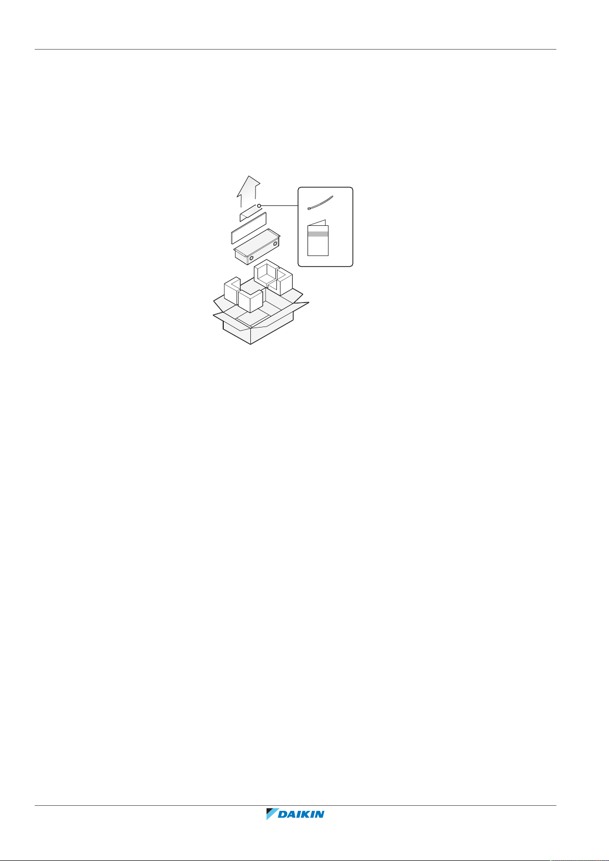
4.1.1 To remove the accessories from the communication box
a Installation manual
b Cable tie (2×)
Installation manual
10
BRR9B1V1
Communication box
4P617761-1B – 2020.10
5 | About the communication box
5 About the communication box
Communication box (BRR9B1V1)
Install the modbus communication box to fully integrate your CO2 Conveni-Pack
system with building control automation networks and other monitoring systems.
NOTICE
ALWAYS check with the reference guide of the installed outdoor unit if the
communication box is compatible with it. Do NOT connect the communication box to
any other unit.
Also see: "8.1About the PCBs"[420].
General names and product names
In this manual, we use the following names:
General name Product name
Communication box BRR9B1V1
Outdoor unit Main outdoor unit. For example:
LRYEN10A7Y1
Capacity up unit Additional outdoor unit for extra
5.1 Identification
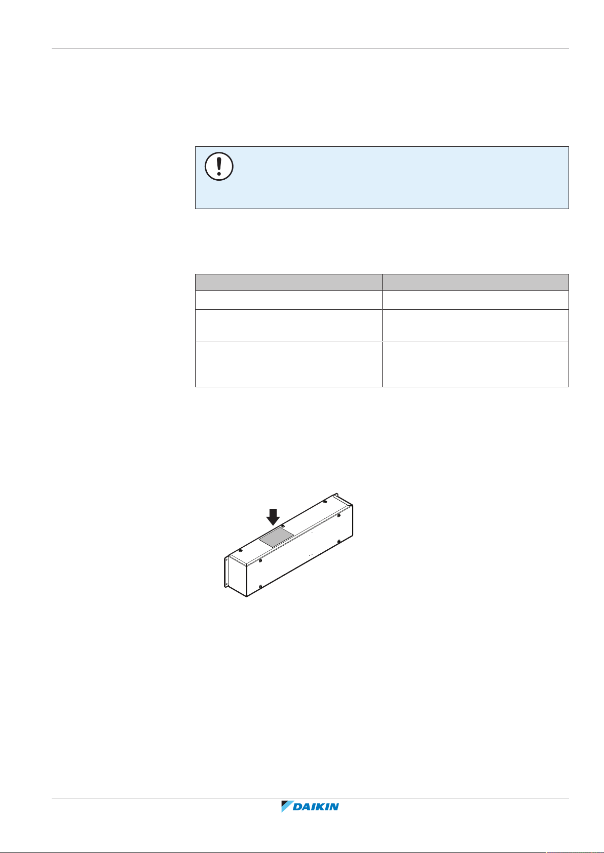
5.1.1 Identification label: Communication box
Location
refrigeration capacity. For example:
LRNUN5A7Y1
BRR9B1V1
Communication box
4P617761-1B – 2020.10
Installation manual
11

6 | Unit installation
≥100 mm ≥50 mm≥300 mm
≥50 mm ≥50 mm
a
b
4×
6 Unit installation
In this chapter
6.1 Preparing the installation site
6.1.1 Installation site requirements of the communication box
6.1 Preparing the installation site ................................................................................................................................................ 12
6.1.1 Installation site requirements of the communication box.................................................................................... 12
6.2 Opening and closing the unit ................................................................................................................................................. 12
6.2.1 To open the communication box ........................................................................................................................... 12
6.2.2 To close the communication box ........................................................................................................................... 13
6.3 Installing the communication box.......................................................................................................................................... 13
6.3.1 Precautions when installing the communication box ........................................................................................... 13
6.3.2 To install the communication box ......................................................................................................................... 13
▪ Mind the following spacing installation guidelines:
6.2 Opening and closing the unit
6.2.1 To open the communication box
a Front view
b Top view
▪ The communication box is designed for indoor installation only and for ambient
temperatures ranging from –5~35°C.
Installation manual
12
4P617761-1B – 2020.10
BRR9B1V1
Communication box

6.2.2 To close the communication box
4×
a
a
aa
515
529
100
120
b
40
87
(mm)
6.3 Installing the communication box
6.3.1 Precautions when installing the communication box
INFORMATION
Also read the precautions and requirements in the following chapters:
▪ General safety precautions
▪ Preparation
6 | Unit installation
6.3.2 To install the communication box
1 Drill 4 holes at the fixing points.
a Hole for a M5 self-tapping screw (4 fixing points)
b Wiring intake
2 Secure the communication box using 4 screws (field supply).
INFORMATION
Install the communication box on a sufficiently strong wall using fixing screws (field
supply) suitable for the wall.
INFORMATION
▪ Make sure that the wiring intakes face downward.
▪ Make sure that dew or rainwater will not drop on the field wiring.
▪ Provide traps in front of the wiring intakes.
BRR9B1V1
Communication box
4P617761-1B – 2020.10
Installation manual
13

7 | Electrical installation
7 Electrical installation
In this chapter
DANGER: RISK OF ELECTROCUTION
WARNING
ALWAYS use multicore cable for power supply cables.
7.1 General overview of the field wiring...................................................................................................................................... 14
7.2 Field wiring: Overview ............................................................................................................................................................ 15
7.3 Guidelines when connecting the electrical wiring................................................................................................................. 16
7.4 Specifications of standard wiring components...................................................................................................................... 16
7.5 To connect the electrical wiring on the communication box................................................................................................ 17
7.6 To connect the transmission wiring ....................................................................................................................................... 18
7.6.1 Between communication box and outdoor unit ................................................................................................... 18
7.6.2 Between communication box and monitoring system ......................................................................................... 18
7.7 To fix the wiring cables with cable ties .................................................................................................................................. 19
7.1 General overview of the field wiring
INFORMATION
Indoor units (air conditioning). This field wiring overview shows only one possible
wiring for the indoor units (air conditioning). For more possibilities, see the indoor
unit manual.
Installation manual
14
BRR9B1V1
Communication box
4P617761-1B – 2020.10

7 | Electrical installation
g
F2F1 F1
X1M (A1P)
F2 Q1 Q2
TO
MULTI UNIT
TO
OUT/D UNIT
TO
IN/D UNIT
L1 L2 L3 N
X1M PE X2M
C C1 W1 R P1 P2
21 3
X3M
L N
X2M
P1 P2 F1 F2 T1 T2
F2F1 F1
X1M (A1P)
F2 Q1 Q2
TO
MULTI UNIT
TO
OUT/D UNIT
TO
IN/D UNIT
L1 L2 L3 N
X1M PEX4M
C C1 W1 R P1 P2
21 3
X5M
L N
X2M
X1M
X1M
P1 P2 F1 F2 T1 T2
P1 P2
L N
X1M PEX3M
A+ B- F1 F2
220-240 V AC
220-240 V AC
220-240 V AC
12 V DC
12 V DC
12 V DC
12 V DC
220-240 V AC
220-240 V AC
220-240 V AC
220-240 V AC
1N~ 50 Hz
220-240 V AC
RS-485
DIII
DIII
DIII
DIII
DIII
f gf
d
ed e
a
i
i
b
d1 d2
h
h1 h2
d1 d2
X1M (A1P)
X5M
X4M
X1M
PE
X1M
X3M
PE
X1M (A1P)
X2M
X1M
X3M
PE
k1
k
l
m
k2
k4
k3
j
3N~ 50 Hz
380-415 V AC
c1
c2
3N~ 50 Hz
380-415 V AC
c1
c2
c1
c2
1N~ 50 Hz
220-240 V AC
c1
c2
k5
R1
R1
RS-485
DIII
R1
BRR9B1V1
Communication box
4P617761-1B – 2020.10
a Capacity up unit (LRNUN5A7Y1) i Indoor unit (air conditioning)
b Outdoor unit (LRYEN10A7Y1) j User interface for indoor units (air conditioning)
c1 Overcurrent fuse (field supply) k Safety system (field supply). Example:
c2 Earth leakage circuit breaker (field supply) k1: Control panel
d Alarm panel (field supply) for: k2: CO2 refrigerant leak detector
d1: Caution output signal k3: Safety alarm (lamp)
d2: Warning output signal k4: Ventilation (natural or mechanical)
e Control panel (field supply) for operation output
signal
f Remote operation switch (field supply) l Communication box (BRR9B1V1)
g Remote low noise switch (field supply) m Monitoring system (field supply)
OFF: normal mode
ON: low noise mode
h Operation output signal to expansion valves of all:
h1: Blower coils (field supply)
h2: Showcases (field supply)
7.2 Field wiring: Overview
Field wiring consists of:
▪ power supply (including earth),
k5: Shut off valve
Wiring:
RS-485 transmission wiring (mind polarity)
DIII transmission wiring (no polarity)
Operation output
Installation manual
15

7 | Electrical installation
▪ DIII transmission wiring between communication box and outdoor unit,
▪ RS‑485 transmission wiring between communication box and monitoring system.
NOTICE
▪ Be sure to keep the power line and transmission line apart from each other.
Transmission wiring and power supply wiring may cross, but may NOT run
parallel.
▪ In order to avoid any electrical interference the distance between both wirings
should ALWAYS be at least 50mm.
Transmission wiring
7‒1 DIII weak current – Transmission wiring between each unit except monitoring system
Transmission wiring specification and limits
(a)
Vinyl cords with 0.75 to 1.25mm² sheath or cables (2‑core wires)
Maximum wiring length 1000m
Total wiring length ≤2000m
(a)
If the total transmission wiring exceeds these limits, communication errors might occur.
7‒2 RS-485 weak current – Transmission wiring between monitoring system and communication
box
Transmission wiring specification and limits
Vinyl cords with 0.75 to 1.25mm² sheath or cables (2‑core wires)
Maximum wiring length 1200m
(a)
If the total transmission wiring exceeds these limits, communication errors might occur.
7.3 Guidelines when connecting the electrical wiring
7‒3 Tightening torque for power supply
Item Tightening torque (N•m)
Terminal block (X1M) (M4) 1.18~1.44
Earth terminal (M5) 3.02~4.08
7‒4 Tightening torque for transmission wiring
Item Tightening torque (N•m)
Communication box terminal block
(X3M) (M3.5)
(a)
0.79~0.97
7.4 Specifications of standard wiring components
Installation manual
16
Outdoor unit terminal block (X1M
0.80~0.96
(A1P)) (M3.5)
7‒5 Power supply and earth wire
Component Specification
Power supply wire Minimum cable section of 2mm²
(Ø1.6mm)
BRR9B1V1
Communication box
4P617761-1B – 2020.10

7 | Electrical installation
a
m
k
j
l
j
≥50 mm
h
g
i
A1P A2P
d
e
f
n
o
p
n
o
p
7±2 mm
a
X1M
c
b
Component Specification
Power supply wire – maximum wiring length 250m
Earth wire 2mm2 (Ø1.6mm)
7.5 To connect the electrical wiring on the communication box
WARNING
▪ Make sure the electrical wiring does NOT obstruct correct reattachment of the
communication box cover. Incorrect reattachment of the communication box
cover might result in electrical shocks, fire, or terminal overheating.
▪ Do NOT connect the power supply wires to the terminal block for the
transmission wiring. Incorrect connection is very dangerous, results in damage,
and possible burnout of the electrical components.
▪ Do NOT use stranded wires with a solder finish applied. A loose wire or other
abnormalities might cause abnormal heating.
See also "7.1General overview of the field wiring"[414].
1 Insert the wiring in the intake hole from the bottom of the communication
box.
BRR9B1V1
Communication box
4P617761-1B – 2020.10
a Intake hole
2 Remove the sheath of the transmission cables.
3 Twist the transmission cables.
4 Connect the power supply to the terminal block (X1M) of the communication
box.
a Sheath
b Twist together before connecting.
c Connect to X1M.
d Round crimp-style terminal
e Insulation sleeve
f Wire
g Round crimp-style terminal
h Cutout section
i Cup washer
j Wiring intake
k Transmission wiring (RS‑485 weak current) to the monitoring system (mind polarity)
Installation manual
17

7 | Electrical installation
7±2 mm
a
X3M
c
b
l Transmission wiring (DIII weak current) to outdoor unit (no polarity)
m Power wire and earth wire (copper)
n Cable clamp
o Cable tie
p Wiring
7.6 To connect the transmission wiring
7.6.1 Between communication box and outdoor unit
5 Connect the earth wire to the earth terminal.
6 Connect the transmission wiring as described in "7.6 To connect the
transmission wiring"[418].
INFORMATION
▪ Mind the maximum length of the transmission wiring. Otherwise transmission
errors might occur.
▪ Use sheathed vinyl cords or cables (2 cores).
▪ Use ONLY 2-core cables. Do NOT use cables with 3 or more cores, otherwise
transmission errors might occur.
Prerequisite: Use DIII weak current wire.
Prerequisite: Cut the end portion of the transmission wiring that has to be
connected. Strip insulation from the wire before connecting it to the terminal block
(X3M).
Prerequisite: Twist the wires together before connecting the wires.
1 Connect F1 and F2 of the X3M terminal block of the communication box to F1
and F2 (TO OUT/D UNIT) of the X1M (A1P) terminal block of the outdoor unit.
2 Connect F1 and F2 (TO OUT/D UNIT) of the X1M (A1P) terminal block of the
outdoor unit to F1 and F2, respectively, of the terminal block of the capacity
up unit.
7‒1 Cut, twist, and connect the wire to the terminal block
a Sheath
b Twist together before connecting.
c Connect to X3M.
7.6.2 Between communication box and monitoring system
Installation manual
18
NOTICE
Mind the polarity of the transmission wiring.
See also "7.1General overview of the field wiring"[414].
Prerequisite: Use RS‑485 weak current wire.
BRR9B1V1
Communication box
4P617761-1B – 2020.10

7 | Electrical installation
7±2 mm
a
X3M
c
b
a
b
c
a
b
c
Prerequisite: Cut the end portion of the transmission wiring that has to be
connected. Strip insulation from the wire before connecting it to the terminal block
(X3M).
Prerequisite: Use wires with the same diameter and twist the core wires together
before connecting the wires.
1 Connect wires from A+ and B– of the terminal block of the communication box
to the monitoring system.
2 Connect the wires to the X3M terminal block in the same way as "Between
communication box and outdoor unit"[418].
7‒2 Cut, twist, and connect the wire to the terminal block
a Sheath
b Twist together before connecting.
c Connect to X3M.
7.7 To fix the wiring cables with cable ties
NOTICE
Transmission wiring is used for communication between the units. Do NOT fix the
transmission wiring together with the power wiring or earth wire. Otherwise
communication errors might occur.
1 Fix the transmission wires using a cable tie (delivered as accessory).
a Cable clamp
b Cable tie
c Wiring
2 Fix the power and earth wires using a cable tie (delivered as accessory).
BRR9B1V1
Communication box
4P617761-1B – 2020.10
a Cable clamp
b Cable tie
c Wiring
3 Cut off the excess part of the cable ties.
4 Seal all gaps to prevent small animals from entering the wiring intake (sealing
material is field supply).
Installation manual
19

8 | Configuration
A1P A2P
8 Configuration
In this chapter
INFORMATION
It is important that all information in this chapter is read sequentially by the installer
and that the system is configured as applicable.
DANGER: RISK OF ELECTROCUTION
8.1 About the PCBs ....................................................................................................................................................................... 20
8.2 Setting the addresses of outdoor units and indoor units...................................................................................................... 20
8.3 To set the addresses of the outdoor unit and capacity up unit ............................................................................................ 21
8.4 To set the addresses of the indoor units ............................................................................................................................... 22
8.5 Configuring the communication box...................................................................................................................................... 22
8.5.1 To configure the communication box PCB for the indoor units ........................................................................... 23
8.5.2 To configure the communication box PCB for the outdoor unit and capacity up unit ........................................ 24
8.1 About the PCBs
The communication box is for connection to an outdoor unit only. Do NOT connect
any other types of units.
The communication box contains 2 PCBs:
A1P PCB for communication with the indoor unit.
A2P PCB for communication with the outdoor unit and capacity up unit.
NOTICE
Communication settings (slave address, baud rate, parity and stop bits) MUST be
made for A1P and A2P.
8.2 Setting the addresses of outdoor units and indoor units
WARNING
▪ When opening the front plate of an outdoor unit during operation, be careful of a
rotating fan. The fan continues rotating for a while even after the operation is
stopped.
▪ Before turning ON the power supply, make sure that the operation switch of the
outdoor unit is turned OFF. You can check this via the inspection hole of the
electrical component box (middle) of the outdoor unit.
▪ After turning ON the power supply, operate the push buttons and check the LED
indication via the inspection hole of the electrical component box (middle) of the
outdoor unit. Operating with the cover open might cause an electrical shock.
▪ For more information on how to configure the monitoring system (field supply),
see the manual of the supplier.
Installation manual
20
BRR9B1V1
Communication box
4P617761-1B – 2020.10

8 | Configuration
a
g
f
i
h
e
d
c
b
OFF
ON
REMOTE
HAP
BS1
DS1 DS2
BS2 BS3
MODEMODE
MODE
MODE
About the effective address range
Set an address in accordance with the model to be connected to the
communication box. The following table shows the numbers to which an address
can be set.
Model Effective address range
Outdoor unit + capacity up unit
1-7
(LRYEN10A7Y1 + LRNUN5A7Y1)
Indoor unit 1‑00 – 4‑15
INFORMATION
The numbers in the table show the effective range of address setting. For the
number of outdoor units that can communicate with 1 communication box, see the
specifications.
▪ The address of an outdoor unit and capacity up unit needs to be different.
▪ Setting an address outside the effective range disables proper communication.
▪ After an address of the outdoor unit and capacity up unit is set or changed, reset
the power supply of the communication box.
8.3 To set the addresses of the outdoor unit and capacity up unit
1 Open the left inspection hole cover.
2 Turn OFF the power supply.
3 Turn OFF the operation switch.
a Inspection hole (left)
b Inspection hole (right)
c Electrical component box
d Operation switch
e PCB (A1P)
f Push buttons (BS1~BS3)
g 7-segments display
h DIP switch
i HAP LED
4 Turn the power supply ON and leave the operation switch OFF.
5 Open the right inspection hole cover.
6 Set the addresses as described in the table below.
Procedure 7-segments display Remarks
Initial indication Show the initial indication in a
normal condition.
BRR9B1V1
Communication box
4P617761-1B – 2020.10
Installation manual
21

8 | Configuration
BS1 BS2 BS3
MODEMODE
MODE
MODE
BS1 BS2 BS3
MODEMODE
MODE
MODE
BS1 BS2 BS3
MODEMODE
MODE
MODE
BS1 BS2 BS3
MODEMODE
MODE
MODE
BS1 BS2 BS3
MODEMODE
MODE
MODE
BS1 BS2 BS3
MODEMODE
MODE
MODE
BS1 BS2 BS3
MODEMODE
MODE
MODE
Procedure 7-segments display Remarks
Press and hold BS1 for 5seconds.
Press BS2 6times.
Press BS3 once.
Press BS2 to
No address set 0 is factory setting. If no setting
select the
desired setting.
Address 1 Displays the total number of
⁞ ⁞ ⁞
Address 63 An address can be setup to 63.
Make sure that the left 7segment is 2.
Check the number of button
presses with the right 7-segment.
(You see number 6 in the right 7segment, this means that you
pressed 6 times on BS2).
This displays the Airnet address.
has been made, communication
cannot be established.
button presses in the 7-segment
(center and right).
When BS2 is pressed after that,
the setting will change to
"Address not set".
Press BS3 once.
Press BS3 once.
Press BS1 once.
8.4 To set the addresses of the indoor units
8.5 Configuring the communication box
When the value is determined,
the 7-segment display changes
from blinking to lit.
—
Returns to the initial indication.
Refer to the installation manual of the controller.
WARNING
▪ Do NOT turn ON the power when the communication box cover is open. An
electrical shock might occur.
▪ Before turning ON the power, make sure that the communication box cover is
closed.
Installation manual
22
BRR9B1V1
Communication box
4P617761-1B – 2020.10

8.5.1 To configure the communication box PCB for the indoor units
A1P
BS1
H1P H2P H3P H4P H5P H6P H7P
SS2 SS3
BS2 BS3 BS4 BS5
1234
DS1
ON
OFF
DS2
1234
120Ω100Ω
SS1
X2M
a
A1P A2P
1 2 3 4 1 2 3 4
DS1 DS2
ON
OFF
Overview of buttons, switches, and other parts
a DIP switches (DS1, DS2)
You can configure 3 different settings on PCB A1P:
▪ RS‑485 Modbus baud rate
▪ Modbus communication parity/stop bit
▪ Modbus slave address setting
RS‑485 Modbus baud rate setting
Setting
8 | Configuration
DS1 pin 2: OFF 9600bps
DS1 pin 2: ON 19200bps
Modbus communication parity/stop bit
Setting
DS1 pin 3: OFF, pin 4: OFF Even 1 stop bit
DS1 pin 3: OFF, pin 4: ON Odd 1 stop bit
DS1 pin 3: ON, pin 4: OFF None 2 stop bits
DS1 pin 3: ON, pin 4: ON None 1 stop bit
Modbus slave address setting
Setting
DS2 pin 1/2/3/4 When Modbus address is set (e.g. 1, ….,
15), then Modbus RS‑485 is enabled.
OFF/OFF/OFF/OFF No Modbus address is set, this means
no Modbus RS‑485 communication.
OFF/OFF/OFF/ON
OFF/OFF/ON/OFF
Address 1
Address 2
BRR9B1V1
Communication box
4P617761-1B – 2020.10
…
ON/ON/ON/ON
…
Address 15
DS1 Switch 2 = baud rate.
DS1 Switch 3+4 = parity stop bits.
DS2 Switch 1~4 = Modbus slave address.
Installation manual
23

8 | Configuration
b
a
c
A2P
BS1
H1P H2P H3P H4P H5P H6P H7P
SS2 SS3
BS2 BS3 BS4 BS5
1234
DS1
ON
OFF
DS2
1234
120Ω100Ω
SS1
X2M
a
b
c
d
A1P A2P
INFORMATION
For more information, see the design guide of Modbus Interface DIII (EKMBDX*).
CAUTION: Precautions when setting the slave address
▪ Do NOT set the same slave address for devices connected to the Modbus master
device.
▪ Apart from the slave address set in the communication box, there are 2 other
slave addresses that cannot be set. When the slave address on the PCB for the
outdoor unit (A2P) is set to "A", slave addresses "A+1" and "A+2" CANNOT be set.
Slave address "A" is used for the outdoor unit, "A+1" is used for the capacity up
unit, and "A+2" may NOT be used.
a Modbus master device
b Communication box 1
c Communication box 2
8‒1 Settings for slave address for communication box 1
PCB A1P A2P
Address set 1 2
Unit/system Indoor Outdoor Capacity up
unit
Valid slave
1 2 3 4
Reserved
address
address
8‒2 Settings for slave address for communication box 2
PCB A1P A2P
Address set 8 5
Unit/system Indoor Outdoor Capacity up
unit
Valid slave
8 5 6 7
Reserved
address
address
8.5.2 To configure the communication box PCB for the outdoor unit and capacity up unit
Overview of buttons, switches, and other parts
Installation manual
24
a LEDs
b Push buttons (BS1~BS5)
BRR9B1V1
Communication box
4P617761-1B – 2020.10

8 | Configuration
DS1
1 2 3 4
DS2
1 2 3 4
ON
OFF
OFF
ON
SS2
120 Ω
SS3
100 Ω
SS2
120 Ω
SS3
100 Ω
OFF
ON
SS2
120 Ω
SS3
100 Ω
SS2
120 Ω
SS3
100 Ω
c DIP switches (DS1, DS2)
d Switches to set the terminating resistance (SS1~SS3)
1 Set the slave address using the DIP switches (DS1, DS2) on PCB A2P of the
communication box.
INFORMATION
Make sure to set the slave address before you turn the power ON. The setting is
invalid when the setting was done after power ON.
Slave
address
1 2 3 4 1 2 3 4
DS1 DS2 Remarks
0 OFF OFF OFF OFF OFF OFF OFF OFF Default
value
1 OFF OFF OFF OFF OFF OFF OFF ON —
2 OFF OFF OFF OFF OFF OFF ON OFF
3 OFF OFF OFF OFF OFF OFF ON ON
…
26 OFF OFF OFF ON ON OFF ON OFF
…
245 ON ON ON ON OFF ON OFF ON Maximum
effective
address
2 If needed, set the terminating resistance. You can set this setting with 2 slide
switches (SS2, SS3). If both switches are "OFF" (default setting), the
terminating resistance is 0Ω.
BRR9B1V1
Communication box
4P617761-1B – 2020.10
8‒1 Example of slide switch settings when resistance is 120Ω
8‒2 Example of slide switch settings when resistance is 100Ω
3 Check all transmission wiring (DIII weak current).
4 Check all transmission wiring (RS‑485 weak current) from the monitoring
system to the communication box.
5 Close the communication box cover when you turn ON the power supply.
6 Set the parity using the push buttons (BS1~BS5) on the A2P PCB of the
communication box. The table below shows the setting method. Set the parity
as specified by the monitoring system.
Installation manual
25

8 | Configuration
Procedure LED indication
(a)
Remarks
H1P H2P H3P H4P H5P H6P H7P
Initial indication Shows the initial indication in
normal conditions.
Press and hold BS1 for 5seconds. Make sure that the H1P LED has
turned ON.
Press BS2 2 times. Check the pressing count against
the LED indication.
Press BS3 once. Indicates the last setting status.
Press BS2 to
select the
desired setting.
None Factory setting
Odd —
Even
Press BS3 once. The LED indication will change
from flashing to ON.
Press BS3 once. —
Press BS1 once. Returns to the initial indication
(a)
= OFF, = ON, and = flashing.
7 Set the baud rate setting using the push buttons (BS1~BS5) on PCB A2P of the
communication box. The following table shows the setting method. Set the
baud rate as specified by the monitoring system.
Procedure LED indication
(a)
Remarks
H1P H2P H3P H4P H5P H6P H7P
Initial indication Shows the initial indication in
normal conditions.
Press and hold BS1 for 5seconds. Make sure that the H1P LED has
turned ON.
Press BS2 once. Check the pressing count against
the LED indication.
Press BS3 once. Indicates the last setting status.
Press BS2 to
select the
desired setting.
9600bps Factory setting
19200bps —
Press BS3 once. The LED indication will change
from flashing to ON.
Press BS3 once. —
Press BS1 once. Returns to the initial indication
(a)
= OFF, = ON, and = flashing.
8 Set the stop bit settings using the push buttons (BS1~BS5) on PCB A2P of the
communication box. The following table shows the setting method. Set the
stop bit settings as specified on the monitoring system.
Procedure LED indication
(a)
Remarks
H1P H2P H3P H4P H5P H6P H7P
Initial indication Shows the initial indication in
normal conditions.
Installation manual
26
Communication box
4P617761-1B – 2020.10
BRR9B1V1

8 | Configuration
Procedure LED indication
(a)
Remarks
H1P H2P H3P H4P H5P H6P H7P
Press and hold BS1 for 5seconds. Make sure that the H1P LED has
turned ON.
Press BS2 6 times. Check the pressing count against
the LED indication.
Press BS3 once. Indicates the last setting status.
Press BS2 to
select the
desired setting.
Auto LED indication is the desired
1 stop bit
setting.
2 stop bits
Press BS3 once. The LED indication will change
from flashing to ON.
Press BS3 once. —
Press BS1 once. Returns to the initial indication
(a)
= OFF, = ON, and = flashing.
9 After the settings are set, reset the power supply of the communication box.
INFORMATION
The power supply must be reset before the settings of parity, baud rate, and stop
bits become effective.
BRR9B1V1
Communication box
4P617761-1B – 2020.10
Installation manual
27

9 | Commissioning
9 Commissioning
INFORMATION
For more information on how to do a test run of each unit, see the installation
manual or installer reference guide of each unit.
Are the LEDs (H1P~H4P) on the PCB (A1P) flashing?
▪ H1P: DIII connection (send).
▪ H2P: DIII connection (receive).
▪ H3P: RS‑485 connection (send).
▪ H4P: RS‑485 connection (receive).
Are the LEDs (H6P, H7P) on the PCB (A2P) ON?
If the LEDs are still flashing, communication is not established.
▪ H6P ON: RS‑485 communication is established.
▪ H7P ON: DIII communication of 1 or more units is established.
Can the operation data of each address be monitored on the monitoring
system?
Make sure that the power supply to each unit is turned ON.
Check that the address set on each unit corresponds with the address
displayed on the monitoring system.
Make sure that the power supply to each unit is turned ON.
Result: If there are no problems with the operation data and the remote settings,
the H2P LED will be OFF and the H6P and H7P LEDs will be ON. The test run is then
complete for A2P.
INFORMATION
▪ Confirmation of an error takes about 12 minutes.
▪ If there is no communication from the monitoring system (e.g. monitoring system
is turned OFF, incorrect polarity or disconnection), a communication error occurs
on the RS‑485 side.
What to do in case of a communication error?
▪ The operation data cannot be checked on the monitoring system.
▪ Check all items in "10Troubleshooting"[429] and correct any problem.
▪ " 10‒1 Operation procedure step 1" [4 30] describes how you can check
some errors.
Installation manual
28
BRR9B1V1
Communication box
4P617761-1B – 2020.10

10 Troubleshooting
In this chapter
10.1 Troubleshooting for PCB for indoor unit communication ..................................................................................................... 29
10.2 Troubleshooting for PCB for outdoor unit and capacity up unit communication ................................................................ 29
10.1 Troubleshooting for PCB for indoor unit communication
What to check? How to check? Solution
10 | Troubleshooting
No Modbus
communication
Incorrect Modbus address setting was present at
power ON on the Modbus interface DIII.
No Modbus address is set (=DS2: OFF/OFF/OFF/
OFF).
During power OFF, set DS2 on A1P to
the required Modbus address. See
"8.4To set the addresses of the
indoor units"[422]. The ON/OFF
status of the DIP switch is detected
only at the time of power ON of the
PCB.
Set DS2 on A1P to the required
Modbus address. See "8.4To set the
addresses of the indoor units"[422].
10.2 Troubleshooting for PCB for outdoor unit and capacity up unit communication
What to check? How to check? Solution
Address setting of each
unit
Slave address setting DIP switches (DS1, DS2) of the communication
Data of each address can be checked on the
monitoring system.
box PCB (A2P).
Set the addresses of the outdoor
unit and capacity up unit again. See
"8Configuration"[420].
Set the slave address correctly. See
"To configure the communication
box PCB for the outdoor unit and
capacity up unit"[424].
Parity setting Parity setting on the monitoring system against
the parity setting on the communication box.
Stop bit setting Stop bit setting on the monitoring system against
the stop bit setting on the communication box.
Baud rate setting Baud rate setting on the monitoring system
against the baud rate setting on the
communication box.
BRR9B1V1
Communication box
4P617761-1B – 2020.10
Set the parity setting correctly. See
"To configure the communication
box PCB for the outdoor unit and
capacity up unit"[424].
Set the stop bit setting correctly. See
"To configure the communication
box PCB for the outdoor unit and
capacity up unit"[424].
Set the baud rate setting correctly.
See "To configure the
communication box PCB for the
outdoor unit and capacity up
unit"[424].
Installation manual
29

10 | Troubleshooting
What to check? How to check? Solution
DIII weak current
Data of each address on the monitoring system. Check the wiring of the unit with
transmission wiring
H2P is ON and H7P is flashing on the
communication box. Follow the instructions in "
10‒1 Operation procedure step 1"[430] to
diagnose the communication box.
RS‑485 weak current
transmission wiring
Make sure that the field settings are made
correctly, check whether the data can be checked
on the monitoring system.
Refrigerator connection
other than an outdoor
unit and capacity up
unit
H2P is ON on the communication box. Follow the
instructions in " 10‒2 Operation procedure
step 2"[431] to diagnose the communication
box.
PCB error H2P is ON on the communication box. Follow the
instructions in " 10‒1 Operation procedure
step 1"[430] to diagnose the communication
box.
No LED is ON on PCB (A2P).
data that cannot be checked and
correct the wiring.
Communication cannot be
established with any of the outdoor
units. Check the transmission wiring
(DIII weak current) and address
settings.
Check RS‑485 weak current
transmission wiring and correct it
(e.g. disconnection, incorrect
polarity).
Disconnect the non-CO₂ refrigerator.
Replace PCB (A2P).
Check conditions of all units (indoor unit, outdoor
unit and capacity up unit).
10‒1 Operation procedure step 1
Procedure LED indication
(a)
Remarks
H1P H2P H3P H4P H5P H6P H7P
Initial indication
(b)
Press BS1 once. —
Press BS2 twice.
H6P flashing: RS‑485
communication error
H7P flashing: DIII communication
error (if communication is not
established with any of the
indoor units).
Installation manual
30
BRR9B1V1
Communication box
4P617761-1B – 2020.10

10 | Troubleshooting
Procedure LED indication
H1P H2P H3P H4P H5P H6P H7P
Press BS3 once
(error check).
DIII side
(c)
communication
error
RS‑485
communication
error
Board error Error of the PCB (A2P) of the
Duplicate
outdoor unit
addresses
Outdoor unit
address not set
Slave address
setting error
(a)
Remarks
Communication error of all
outdoor units.
(d)
Communication error on the
RS‑485 side. An error is detected
even when the polarity is correct.
Check the address settings and
the RS‑485 wiring.
(d)
communication box. Replace the
PCB.
Duplicate outdoor unit addresses.
Check the address settings and
DIII wiring.
The address of an outdoor unit is
not set. Check the address setting
and DIII wiring.
Slave address setting error. Check
the slave address setting and
wiring.
Press BS1 once. In normal conditions, H2P is OFF,
and H6P and H7P are ON.
(a)
= OFF, = ON, and = flashing.
(b)
The initial indication in the table shows the indication when an error is detected. If there are no communication errors, the H2P
LED is OFF and the H6P and H7P LEDs are ON.
(c)
When multiple errors are detected, multiple LEDs (H2P to H7P) are flashing.
(d)
For both DIII side and RS‑485 side, if a communication error occurs after the communication is confirmed, an error is generated. If
the communication has not been confirmed, errors are not detected.
10‒2 Operation procedure step 2
Procedure LED indication
(a)
Remarks
H1P H2P H3P H4P H5P H6P H7P
Initial indication
(b)
H6P flashing: RS‑485
communication error.
H7P flashing: DIII communication
error (if communication is not
established with any of the
indoor units).
Press BS1 once. —
Press BS2 3 times.
Press BS3 once
(error check).
Reserve
Reserve
Different
refrigerator
A non-CO₂ refrigerator is
connected.
Press BS1 once. In normal conditions, H2P turns
OFF, and H6P and H7P turn ON.
BRR9B1V1
Communication box
4P617761-1B – 2020.10
Installation manual
31

10 | Troubleshooting
(a)
= OFF, = ON, and = flashing.
(b)
The initial indication in the table shows the indication when an error is detected. If there are no communication errors, the H2P
LED is OFF and the H6P and H7P LEDs are ON.
Installation manual
32
BRR9B1V1
Communication box
4P617761-1B – 2020.10

11 Technical data
11.1 Wiring diagram: Communication box
A1P PCB (communication with indoor unit for air
conditioning)
A2P PCB (communication with outdoor unit and capacity
up unit)
A3P PCB
BS1~BS5 Push buttons (see Note1)
DS1, DS2 DIP switches (see Note1)
F1S Varistor
F1U Fuse (T, 3.15A, 250V)
H1P~H7P LED
HAP LED
11 | Technical data
SS1~SS3 Switches to set the terminating resistance (see Note
1)
T1R Transformer (220~240V/22V)
X3A~X11A Connectors
X1M~X3M Terminal strips
Field wiring
Terminal strip
Connector
Protective earth
BLK Black
ORG Orange
WHT White
YLW Yellow
HIGH VOLTAGE High voltage
LOW VOLTAGE Low voltage
BRR9B1V1
Communication box
4P617761-1B – 2020.10
MONITORING SYSTEM Monitoring system
OUTDOOR UNIT Outdoor unit
POWER SUPPLY Power supply
SWITCH BOX Switch box
Note1
Communication settings can be changed using the push buttons. For information
on how to do this, see the installation manual of the outdoor unit and the capacity
up unit.
Installation manual
33

12 | Glossary
12 Glossary
Dealer
Sales distributor for the product.
Authorised installer
Technical skilled person who is qualified to install the product.
User
Person who is owner of the product and/or operates the product.
Applicable legislation
All international, European, national and local directives, laws, regulations
and/or codes that are relevant and applicable for a certain product or
domain.
Service company
Qualified company which can perform or coordinate the required service to
the product.
Installation manual
Instruction manual specified for a certain product or application, explaining
how to install, configure and maintain it.
Operation manual
Instruction manual specified for a certain product or application, explaining
how to operate it.
Maintenance instructions
Instruction manual specified for a certain product or application, which
explains (if relevant) how to install, configure, operate and/or maintain the
product or application.
Accessories
Labels, manuals, information sheets and equipment that are delivered with
the product and that need to be installed according to the instructions in
the accompanying documentation.
Optional equipment
Equipment made or approved by Daikin that can be combined with the
product according to the instructions in the accompanying documentation.
Field supply
Equipment NOT made by Daikin that can be combined with the product
according to the instructions in the accompanying documentation.
Installation manual
34
BRR9B1V1
Communication box
4P617761-1B – 2020.10


4P617761-1 B 0000000%
Verantwortung für Energie und Umwelt
Copyright 2020 Daikin
4P617761-1B 2020.10
 Loading...