


INSTALLATION MANUAL
Communication Box
BRR9A1V1
Installation manual
Communication Box
Installationsanleitung
Kommunikationsbox
Manuel d’installation
Boitier de Communication
Installatiehandleiding
Communicatie Box
Manual de instalación
Caja de comunicación
Manuale di installazione
Casetta di comunicazione
Manual de instalação
Caixa de Comunicação
English
Deutsch
Français
Nederlands
Español
Italiano
Portugues
124
X2M
ZEAS
ZEAS
ZEAS
X2M
X1M(A1P)
X1M(A1P)
A1P A1P
F1
F2
A+
B–
A1P
X1M
X3M
4
5
3
1
88
8
1
1
1
2
10
21
TO OUT / D UNITTO IN / D UNIT
F1 F2F1 F2 Q1 Q2
TO MULTI / UNIT
F1 F2
TO OUT / D UNIT
F1 F2
TO IN / D UNIT
Q1 Q2
TO MULTI / UNIT
12T1 T2 F1 F2 12T1 T2 F1 F2
1
2
5
6
7
7
87
100
40
379
8
365
6
7
2
5
9
3
1
4
1
2
9
9
1
1
1
1
11
1
1
11
8
88
8
8
8
X2M
CVP
CVP
X2M
X1M(A1P)
6
F1
F2
A+
B–
7
7
A1P
X1M
X3M
4
5
3
2
10
21
TO OUT / D UNITTO IN / D U NIT
F1 F2F1 F2 Q1 Q2
TO MULTI / UNIT
12T1 T2 F1 F2 12T1 T2 F1 F2
X2M
X2M
12T1 T2 F1 F2 12T1 T2 F1 F2
P1P2
P1P2
F1F2
P1P2
F1F2
P1P2
P1P2
F1F2
P1P2
F1F2
CVP
X1M(A1P)
TO OUT / D UNITTO IN / D U NIT
F1 F2F1 F2 Q1 Q2
TO MULTI / UNIT
1
2
5
3
1 (A, B)
7±2 mm
1
A
X3M
2
1
B
1
C
2
3
4
X1M
X3M
2 (C)
6
3
4
4
7
6
5
2 (C)
8 (D)
5
2
1
8
1
2
10
6
3
9
3
REMOTE
4
OFF
5
ON
6
LED
(H1P~H8P)
7
7
D
3
2
1
11
10
9
8
LED
8
9
7
6
5
10
SS3
DS2
A1P
1 42
1007
1207
OFF
4
ON
RS-485
DS1
SS2
X2M
2 3
BS4BS1 BS3BS2 BS5
1 3
1
3
2
4
12
11
(H1P~H8P)
1
11
X205A A2P
3
2
REMOTE OFF ON
S1S
F3U
S2
F2
F1
T2
T1
X2M
5
1
2
4
12
BRR9A1V1
Communication Box
Installation manual
CONTENTS
1. Safety precautions ......................................................................1
2. Components ................................................................................ 1
3. Main specifi cations ...................................................................... 1
4. Installing the communication box ................................................ 1
5. Electrical wiring work ..................................................................2
5-1 Connecting the transmission wiring (weak current; DIII) ....... 2
5-2 Connecting the transmission wiring
(weak current; RS-485) ......................................................... 3
5-3 Connecting the power wire ...................................................3
5-4 Securing the fi eld wires (transmission wiring and
power wire) ........................................................................... 4
5-5 Notes .................................................................................... 4
6. Field confi guration ....................................................................... 5
6-1 Setting the addresses of outdoor units (ZEAS, CVP),
booster units, and indoor units (air conditioner) .................... 5
6-2 Confi guring the communication box ..................................... 8
7. Test-running the communication system ................................... 10
8. Delivering the product ............................................................... 12
The English text is the original instruction. Other languages are
translations of the original instructions.
Safety precautions1.
Please read these “Safety precautions” carefully before installing
the communication box and be sure to install it correctly.
For information on the installation of ZEAS, CVP, booster units, and
indoor units (air conditioner), refer to the installation manual
included with the respective equipment.
Meaning of WARNING and CAUTION notices
WARNING
Failure to follow these instructions properly
may result in personal injury or loss of life.
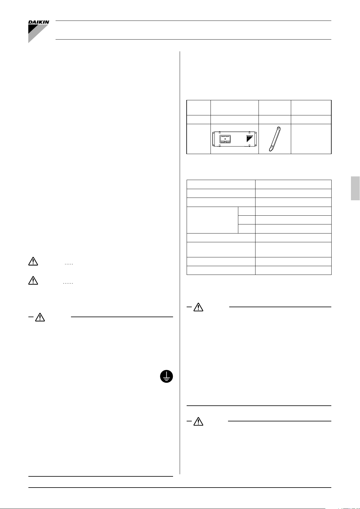
Components2.
The following table shows the components of the communication
box.
The screws for securing the communication box must be arranged
locally.
Do not dispose of the accessories; they will be required in the
installation.
Name Communication box
Quantity 1 unit 2 units 1 copy
Shape
Clamping
material
Manuals etc.
Installation •
manual (this
document)
Main specifi cations3.
Ambient Temp. range –20 - 60°C
Power supply 1 phase 220-240V 50Hz
Input 6.9W
H 124
Dimensions
Casing hot-dip zinc-coated S S
Comm. protocol
Mass 2.1kg
Location Indoor installed
W 379
D87
Mod bus RS-485
two-wires system
CAUTION
WARNING
Ask your dealer or qualifi ed personnel to carry out installation •
work.
Do not attempt to install the condensing unit yourself. Improper
installation may result in water leakage, electric shocks or fi re.
Make sure that a separate power supply circuit is provided for this
•
unit and that all electrical work is carried out by qualifi ed personnel
according to local laws and regulations and this installation manual.
• Be sure to earth the communication box.
Do not earth the unit to a utility pipe, lightning conductor or
telephone earth lead. Imperfect earthing may result in
electric shocks or fi re.
A high surge current from lightning or other sources may cause
damage to the communication box.
Be sure to switch off the unit before touching any electrical parts.•
Make sure that all wiring is secured, the specifi ed wires are used, •
and that there is no strain on the terminal connections or wires.
Improper connections or securing of wires may result in abnormal heat build-up or fi re.
When wiring the power supply and connecting transmission •
wiring, position the wires so that the control box cover can be
securely fastened.
Improper positioning of the control box cover may result in
electric shocks, fi re or the terminals overheating.
Do not touch the switch with wet fi ngers.•
Touching a switch with wet fi ngers can cause electric shock.
Failure to observe these instructions properly
may result in property damage or personal
injury, which may be serious depending on
the circumstances.
Installing the communication box4.
WARNING
For information on the installation of ZEAS, CVP, booster units, •
and indoor units (air conditioner), refer to the installation manual
included with the respective equipment.
Install the communication box in accordance with the instructions •
in this installation manual.
Improper installation may result in water leakage, electric shocks
or fi re.
Be sure to use only the specifi ed accessories and parts for •
installation work.
Failure to use the specifi ed parts may result in the unit falling,
water leakage, electric shocks or fi re.
Carry out the specifi ed installation work after taking into account •
strong winds, typhoons or earthquakes.
Failure to do so during installation work may result in the unit
falling and causing accidents.
CAUTION
Do not install the communication box in the following locations:•
Where there is a high concentration of mineral oil spray or 1.
vapour (e.g. a kitchen).
Plastic parts will deteriorate, parts may fall off and water
leakage could result.
Near machinery emitting electromagnetic radiation.2.
Electromagnetic radiation may disturb the operation of the
control system and result in a malfunction of the unit.
English 1

Where fl ammable gas may leak, where there is carbon fi ber or 3.
ignitable dust suspensions in the air, or where volatile fl ammables such as paint thinner or gasoline are handled.
Operating the unit in such conditions may result in fi re.
Places with excessive voltage fl uctuations.4.
Communication box may malfunction.
Places that become small animals’ shelter.5.
Small animals coming in contact with electrical parts can
cause malfunctions, smoke, or ignition.
Excessive tightening of a terminal screw may damage the screw.•
Use copper conductors only.•
Use insulated wire for the power cord.•
Select the power supply cable type and size in accordance with •
relevant local and national regulations.
Specifi cations for local wiring are in compliance with IEC60245.•
Use wire type H05VV when protected pipes are used.•
Use wire type H07RN-F when protected pipes are not used.•
Drill pilot holes at the fi xing points as shown in fi gure 1.(1)
Secure the communication box on a suffi ciently strong place (2)
such as a wall by using fi xing screws (locally arranged).
When you fi x the communication box on a material other than
iron plates, use screws suitable for the material to fi x the
communication box securely.
When you install the communication box, make the wire (3)
intakes face downward as shown in fi gure 1.
When you install the communication box with the wiring
intakes facing sideways, ensure that formed dew or rainwater
will not drop on the fi eld wires and provide traps in front of the
intakes.
(Refer to fi gure 1)
External dimensions and fi xing points1.
Pilot hole for a M5 self-tapping screw (4 points)2.
Wire intake3.
Service space4.
300 mm or more5.
50 mm or more6.
50 mm or more7.
100 mm or more8.
50 mm or more9.
Electrical wiring work5.
CAUTION
All fi eld wiring and components must be installed by a licensed •
electrician and must comply with relevant local and national
regulations.
Be sure to use a dedicated power circuit. Never use a power •
supply shared by another appliance.
Connect to the power wire a handy switch that can disconnect all •
poles securely.
Do not connect the ground wire to gas pipes, sewage pipes, •
lightning rods, or telephone ground wires.
Gas pipes: can explode or catch fi re if there is a gas leak.
Sewage pipes: no grounding effect is possible if hard plastic
piping is used.
Telephone ground wires and lightning rods: dangerous when
struck by lightning due to abnormal rise in electrical potential in
the grounding.
Connect the wires in accordance with “Electric Wiring Diagram •
Nameplate” attached on the back side of the communication box
cover.
The transmission wiring (weak current; DIII) and the transmission •
wiring (weak current; RS-485) are transmission wiring for control
line.
Do not clamp the transmission wiring with heavy-current wires or
earth wires. Communication malfunction may occur.
Do not connect a heavy-current wire to the terminal block to •
which the transmission wiring (weak current; DIII) and the
transmission wiring (weak current; RS-485) are to be connected.
Such an incorrect connection is very dangerous, potentially
causing damage to and/or burnout of the electrical components.
Do not use stranded wires with a solder fi nish applied.•
A loose wire or other abnormalities may cause abnormal heating.
Connect only the specifi ed wires and connect them securely so •
that no external force will be applied on the terminals.
Connecting the transmission wiring (weak 5-1
current; DIII)
CAUTION
Observe the specifi ed length of the transmission wiring (weak •
current; DIII): non-observance may cause transmission errors.
For the transmission wiring (weak current; DIII), use sheathed •
vinyl fl exes or cables (two cores).
For the transmission wiring (weak current; DIII), use two-core •
wires.
Do not use a wire with three or more cores; otherwise, transmission errors may occur.
Wiring specifi cations
For information on the specifi cations of the power and (1)
communication wires for ZEAS, CVP, and booster units, refer
to the included installation manuals.
The following table shows the specifi cations of the transmis-(2)
sion wiring (weak current; DIII).
Wire Thickness (mm²) Max. wire length
Transmission
wiring (weak
current; DIII)
Wiring procedure
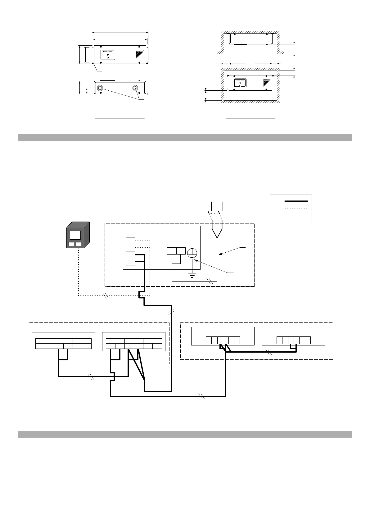
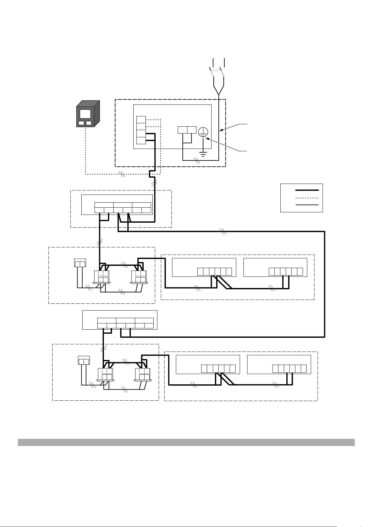
Figures 2 and 3 show the wiring diagrams for connecting the
communication box and each unit (ZEAS, CVP, booster units,
indoor units (air conditioner)).
Connect wires as follows:
Wiring between the communication box and ZEAS/CVP(1)
Connect F1 and F2 of the terminal block (X3M) of the
communication box to F1 and F2 (TO OUT/D UNIT) of the
terminal block (X1M (A1P)) of ZEAS/CVP.
Wiring between ZEAS/CVP(2)
Connect F1 and F2 (TO OUT/D UNIT) of the terminal block
(X1M (A1P)) of a ZEAS/CVP to F1 and F2, respectively, of the
terminal block of another ZEAS/CVP.
Wiring of indoor units (air conditioner) and booster units(3)
The connecting method is the same as the previous one.
Refer to the installation manual of the respective unit.
(Refer to fi gure 2, 3)
Transmission wiring (weak current; DIII)1.
0.75 - 1.25
1000 m
(max. wire length)
2000 m
(total wire length)
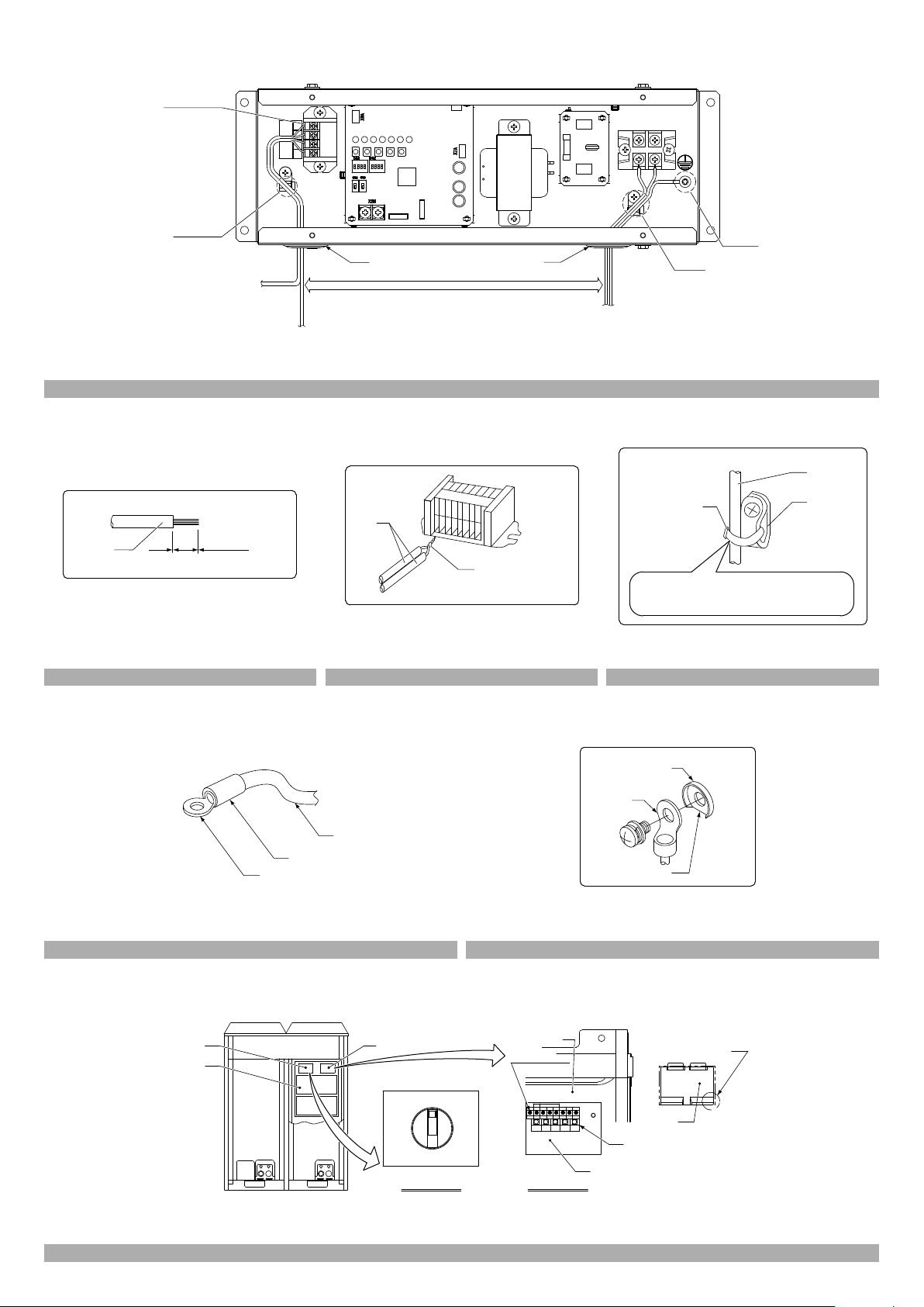
2 English

How to connect the terminal block (X3M) of the communication
box
For information on how to wire the terminal block (X3M) of the
communication box, refer to fi gures 4 to 6.
Tightening torque of the terminal screws of the terminal block (1)
(X3M)
For the tightening torques of the terminal screws, refer to the
following table and use an appropriate screwdriver for
tightening.
A screwdriver of an inadequate size can damage the screw
head, preventing appropriate tightening.
Tightening torque (N·m)
<Communication box>
Terminal block (X3M)
<Outdoor unit (ZEAS/CVP)>
Terminal block (X1M (A1P))
Preparation of wires(2)
As shown in fi gure 5, cut the end portion of the transmission
wiring to be connected and unsheathe the wire before
connecting it to the terminal block (X3M).
When connecting multiple wires from the terminal block (X3M)(3)
To connect two wires to the terminal block (X3M), use wires
with the same diameter and twist the core wires together as
shown in fi gure 6 before connecting the wires.
(Refer to fi gure 4)
Refer to fi gure 5 to make a connection.1.
Transmission wiring (weak current; DIII)3.
To ZEAS or CVP (there is no polarity)
(Refer to fi gure 5)
Sheath1.
(Refer to fi gure 6)
Wires with the same diameter1.
Twist together before connecting2.
0.79 - 0.97
0.80 - 0.96
Connecting the transmission wiring (weak 5-2
current; RS-485)
CAUTION
The transmission wiring (weak current; RS-485) have polarity.•
Incorrect wiring disables communication.
Wiring specifi cations
The following table shows the specifi cations of the transmis-(1)
sion wiring (weak current; RS-485).
Wire Thickness (mm²) Max. wire length
Transmission wiring
(weak current; RS-485)
Wiring procedure
Wiring between the communication box and the monitoring (1)
system
Figures 2 and 3 show the wiring diagrams for connecting the
communication box and the monitoring system.
As shown in fi gures 2 and 3, connect wires from A+ and B– of
the terminal block of the communication box to the monitoring
system.
(Refer to fi gure 2, 3)
Transmission wiring (weak current; RS-485)2.
Monitoring system3.
Communication Box7.
Booster unit8.
0.75 - 1.25 1200 m
Indoor unit (Air conditioner)9.
Switch10.
How to wire the terminal block (X3M) of the communication
box
Connect wires to the terminal block (X3M) in the same way as (1)
“5-1. Connecting the transmission wiring (weak current;
DIII)”.
(Refer to fi gure 4)
Refer to fi gure 5 to make a connection.1.
Transmission wiring (weak current; RS-485) (It has polarity)4.
To the monitoring system
(Refer to fi gure 5)
Sheath1.
(Refer to fi gure 6)
Wires with the same diameter1.
Twist together before connecting2.
Connecting the power wire5-3
Wiring specifi cations
The following table shows the specifi cations of the earth wire (1)
and the power wire of the communication box.
Power wire
Min. thickness
(*1)
2 mm² (φ1.6 mm)
or more
*1. Selections are made based on the VV cable and the IV wire
(electrical conduit work).
*2. The maximum line length is based on a voltage sag of 2%.
Wiring procedure
Figures 2 to 4 and 7 to 9 show the drawings of the power wire.
Connect a power wire (heavy current) to the terminal block (1)
(X1M) of the communication box.
Connect a power wire and an earth wire by using round •
crimp-on terminals.
As shown in fi gure 8, provide insulation to heavy-current •
wires such as by installing an insulation sleeve.
Connect an earth wire to the earth terminal of the communica-(2)
tion box.
Connect the earth wire so that it comes out from the cutout •
section of the cup washer as shown in fi gure 9.
Tightening torque of the terminal screws of the terminal block (3)
(X1M), Earth terminal
For the tightening torques of the terminal screws, refer to the
following table and use an appropriate screwdriver for
tightening.
A screwdriver of an inadequate size can damage the screw
head, preventing appropriate tightening.
<Communication box>
Terminal block (X1M)
<Communication box>
Earth terminal
(Refer to fi gure 2, 3)
Power supply Single phase 220 to 240 V4.
Power supply line5.
Earth line (copper)6.
Max. line length
(*2)
250 m
Tightening torque (N·m)
Earth wire (copper)
2 mm² (φ1.6 mm)
or more
1.18 - 1.44
3.02 - 4.08
English 3

(Refer to fi gure 4)
Power wire, Earth wire (copper)5.
Earth terminal (M4)8.
(Refer to fi gure 8)
Round crimp-on terminal1.
Insulation sleeve2.
Wire3.
(Refer to fi gure 9)
Cutout section1.
Round crimp-on terminal2.
Cup washer3.
Securing the fi eld wires (transmission wiring 5-4
and power wire)
Securing the transmission wiring (weak current)(1)
Refer to fi gure 7 to secure the transmission wiring (weak
current; DIII) and the transmission wiring (RS-485) by using
the included clamping materials.
Securing the power wire and earth wire(2)
Refer to fi gure 7 to secure the power wire and the earth wire
by using the included clamping materials.
(Refer to fi gure 4)
Refer to fi gure 7 to cut an excess end portion after tighten-2.
ing the clamping material on the fi xture.
(Refer to fi gure 7)
Clamping material (accessory)1.
Wire2.
Fixture3.
After tightening the clamping material on the fi xture, cut an 4.
excess end portion.
Notes5-5
As shown in fi gure 4, position the heavy-current wires 50mm (1)
or more apart from the weak-current wires.
If a small animal may enter the intake, fi ll the gaps with putty or (2)
other closing material (locally procured).
(Refer to fi gure 4)
Intake6.
Position heavy current 50 mm or more apart from weak 7.
current
4 English

Field confi guration6.
Setting the addresses of outdoor units (ZEAS, CVP), booster units, and indoor units (air conditioner)6-1
CAUTION
Whenever you open the front plate of an outdoor unit during operation, be careful of the rotation of the fan. The fan of the outdoor unit may •
continue rotating for a while even after the operation is stopped.
Before power on, make sure that the operation switch of outdoor unit (ZEAS, CVP) is turned “OFF” from the inspection hole in the cover of •
the control box.
After power on, operate the push button switches and check the LED indication from the inspection hole in the control box. Operating with •
the cover open may cause an electric shock.
For information on the fi eld confi guration method of the monitoring system (product of other manufacturer), make an inquiry to the appropri-•
ate monitoring system manufacturer.
Effective address range(1)
Set an address in accordance with the model to be connected to the communication box. The following table shows the numbers to
which an address can be set.
Note
The numbers in the following table show the effective range of address setting. For the number of outdoor units that can communicate
with one communication box, refer to the specifi cations.
Pattern Effective address range
ZEAS 1 - 32
CVP (+Booster unit) 1 - 10
ZEAS+Booster unit 1 - 10
Remarks *1 · *2
*1. For outdoor units to which a booster unit or an air conditioner indoor unit is connected (ZEAS/CVP), set the addresses to 1 to 10. For
only ZEAS to which no booster unit will be connected, the address can be set to 11 or later.
*2. Set the addresses for ZEAS, CVP, and ZEAS+Booster unit avoiding duplication.
*3. For a booster unit and an air conditioner indoor unit, set the address within the range shown in the following table.
Effective address range
Booster unit 1 - 3
Indoor unit (Air conditioner) 2 - 61
*4. Setting an address outside the effective range disables proper communication.
*5. After an address of ZEAS, CVP, a booster unit, or an indoor unit is set or changed, be sure to cycle the power to the communication
box.
English 5

How to set the addresses of ZEAS and CVP(2)
As shown in fi gure 10, make sure that the operation switch is turned “OFF” from the inspection hole (left).1.
Turn the power on.2.
Set the address with the following steps. (The setting method is the same for ZEAS and CVP.)3.
Operation procedure
Initial indication
Press and hold the page break button
(BS1) for 5 seconds.
Press the operation button (BS2) 6 times.
Press the confi rmation button (BS3) once.
Address not set
Address 1
Address 2
Press the operation
button (BS2) to select
the desired setting.
Press the confi rmation button (BS3) once.
Press the confi rmation button (BS3) once.
Press the page break button (BS1) once.
*1. The LED indication in the above table shows the case of address setting to 3.
*2. Although an address can be set up to 63, set the address within the effective range.
*3. After an address of ZEAS, CVP, a booster unit, or an indoor unit is set or changed, be sure to
cycle the power to the communication box.
Address 3
Address 4
Address 5
Address 6
· · ·
Address 63
H1P H2P H3P H4P H5P H6P H7P
hhkhhhh
khhhhhh
khhhk kh
khhhhhh
khhhhhh
khhhhhl
khhhhlh
khhhhll
khhhlhh
khhhlhl
khhhl lh
kllllll
khhhhk k
khhhhhh
hhkhhhh
LED indication
Shows the initial indication in a normal condition.
Make sure that the LED (H1P) has turned ON.
Check the pressing count against the LED
indication.
Indicates the current address in binary numbers.
All OFF by factory setting.
If the setting has not been made, communication cannot be established.
Indicates the pressing count on the LEDs
(H2P to H7P) in binary numbers.
· · ·
An address can be set up to 63, and when
BS2 is pressed after that, the setting will
change to “Address not set” (all OFF).
The LED indication of the set address will
change from blinking to ON. (*1)
Returns to the initial indication.
Remarks
<Meaning of indications>
OFF: h ON: k Blinking:
l
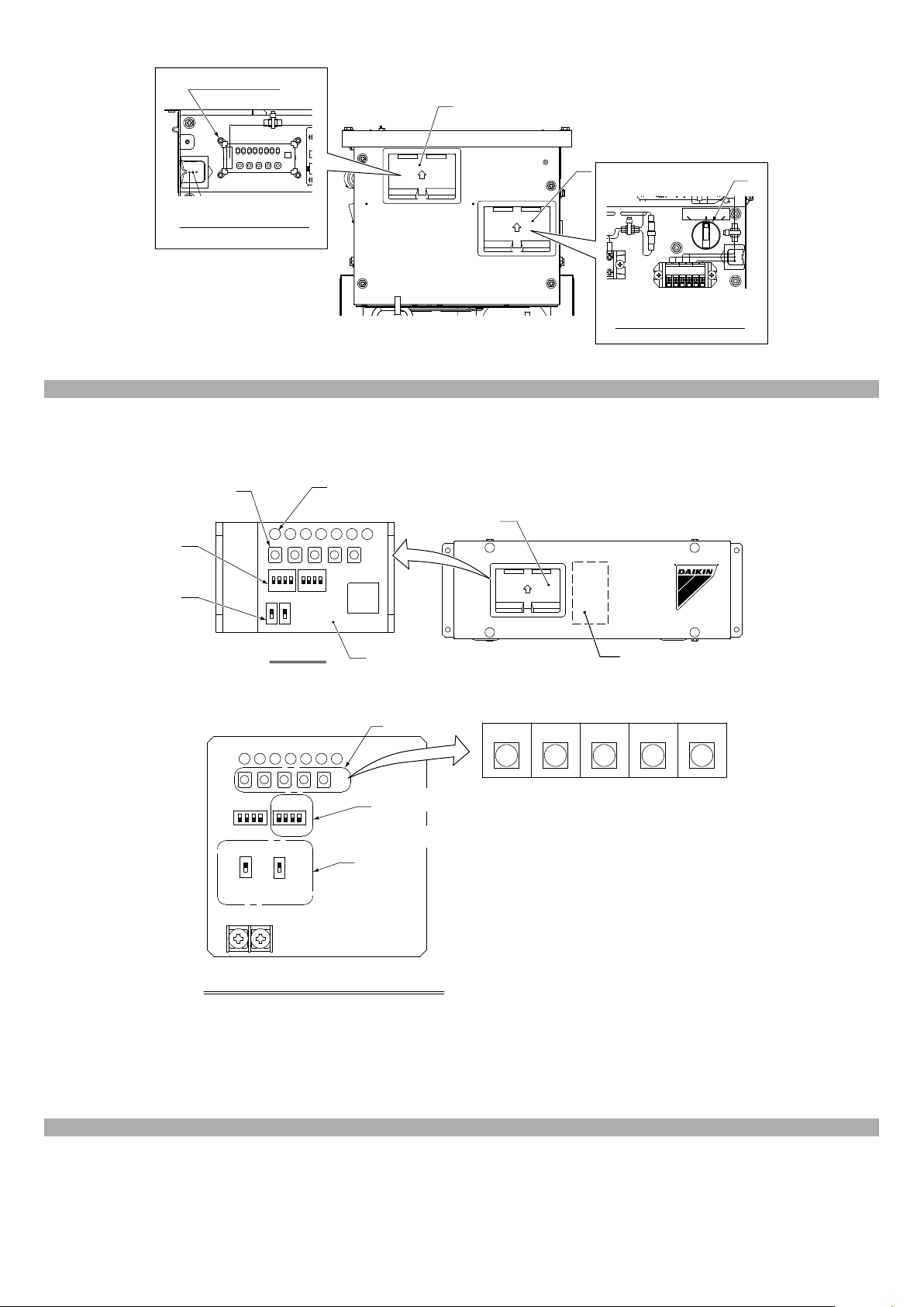
(Refer to fi gure 10)
Inspection hole (left)1.
Control box2.
Inspection hole (right)3.
Operation switch (at the time of ship-4.
ment)
Inspection hole (left)5.
Control box cover6.
Inspection hole (right)7.
PC board (A1P)8.
Push button switches9.
Inspection hole cover10.
Lift up this projection to open the cover.11.
6 English

How to set the addresses of booster units(3)
As shown in fi gure 11, make sure that the operation switch is turned “OFF” from the inspection hole (right).1.
Turn the power on.2.
Set an address with the following steps.3.
Operation procedure
Initial indication
Press and hold the page break button
(BS1) for 5 seconds.
Press the operation button (BS2) 16 times.
Press the confi rmation button (BS3) once.
Address not set
Address 1
Address 2
Press the operation
button (BS2) to select
the desired setting.
Press the confi rmation button (BS3) once.
Press the confi rmation button (BS3) once.
Press the page break button (BS1) once.
*1. The LED indication in the above table shows the case of address setting to 3.
*2. Although an address can be set up to 7, set the address within the effective range.
*3. After an address of ZEAS, CVP, a booster unit, or an indoor unit is set or changed, be sure to
cycle the power to the communication box.
Address setting number
Booster unit
Address of
ZEAS or CVP
1123
2123
3123
4123
10 1 2 3
Address 3
Address 4
Address 5
Address 6
Address 7
Bu1 Bu2 Bu3
· · ·
H1P H2P H3P H4P H5P H6P H7P
hhkhhhh
khhhhhh
khkhhhh
khhhhhh
khhhhhh
khhhhhl
khhhhlh
khhhhll
khhhlhh
khhhlhl
khhhllh
khhhl ll
khhhhk k
khhhhhh
hhkhhhh
LED indication
Shows the initial indication in a normal condition.
Make sure that the LED (H1P) has turned ON.
Check the pressing count against the LED
indication.
Indicates the current address in binary numbers.
All OFF by factory setting.
If the setting has not been made, communication cannot be established.
Indicates the pressing count on the LEDs
(H2P to H7P) in binary numbers.
An address can be set up to 7, and when BS2
is pressed after that, the setting will change to
“Address not set” (all OFF).
The LED indication of the set address will
change from blinking to ON. (*1)
Returns to the initial indication.
Remarks
<Meaning of indications>
OFF: h ON: k Blinking:
l
(Refer to fi gure 11)
Inspection hole (left)1.
Inspection hole (right)2.
Opened detail (left)3.
Opened detail (right)4.
Operation switch (at the time of ship-5.
ment)
English 7

How to set the addresses of indoor units (air conditioner)(4)
Make sure that the operation switch of the remote controller is turned “OFF”.
For information on how to assign an address, refer to the following fi gure.
Basic
Screen
Press “ ”
button for
5 seconds.
Press “ ” button
for once.
After changing the group No.
with the “ ” and “ ” buttons,
press the “ ” button.
Field
setting
Field setting
Test operation ON/OFF
Register Service Contract
Field setting list
Indoor unit Airnet No. set
Error record
Indoor status display
Setting
Select “Indoor unit Airnet No. Set”
and then press the “ ” button.
Press the “ ” button.
1/2
Indoor unit
Airnet No.set
Indoor unit Airnet No.set
Unit No Group No
0 000
Return
Press the
“ ” “ ” button.
Set
Indoor unit
Airnet No.set
Indoor unit Airnet No.set
Unit No Group No
Set
0 000
ReturnReturn
Release
Field setting menu Item 2
Field setting Indoor unit Airnet No. set
Explanation
An indoor unit Airnet address can be set.
*1. Although an address can be set up to 128, set the address within the effective range.
*2. After an address of ZEAS, CVP, a booster unit, or an indoor unit is set or changed, be sure to cycle the power to the communication
box.
Example of address setting numbers
Air conditioner
indoor unit
Address of CVP
Air conditioner
indoor unit 1
Air conditioner
indoor unit 2
· · ·
Air conditioner
indoor unit 6
1 2 3 · · · 7
2 8 9 · · · 13
3 14 15 · · · 19
4 20 21 · · · 25
· · ·
10 56 57 · · · 61
1. Even when remote group control is performed, the address in each indoor unit needs to be set.
Confi guring the communication box6-2
CAUTION
Do not turn the power on with the product cover open. An electric shock may occur.•
Before power on, make sure that the covers of the communication box and of the inspection hole are closed.•
After power on, if the push-button switches need to be operated or the LED indication checked, open the cover of the inspection hole for the •
operation/check.
When you open the inspection hole cover for operation, exercise caution so as not to touch the transformer. A burn may result.•
8 English

Setting a slave address(1)
Set a slave address as follows by using the DIP switches (DS1, DS2) on the PC board (A1P) of the communication box shown in fi gure
12.
CAUTION
Be sure to set a slave address before power on. A setting which is made after power on is invalid.•
Slave
MSB
ON
OFF
Set a terminating resistance as necessary.(2)
The setting can be made with two slide switches (SS2, SS3) shown in fi gure 12. If both slide switches SS2 and SS3 are “OFF”, the
terminating resistance is 0 Ω.
Factory setting
DS1
1234
High-order
4 bits
Slave address setting DPS
Factory setting
( the position
of a switch)
SS2
SS3
DS2
1234
Low-order
4 bits
setting change 1 <1207>
SS2
LSB
address
1 OFF OFF OFF OFF OFF OFF OFF ON Factory setting value
2 OFF OFF OFF OFF OFF OFF ON OFF
3 OFF OFF OFF OFF OFF OFF ON ON
26 OFF OFF OFF ON ON OFF ON OFF
245 ON ON ON ON OFF ON OFF ON Maximum effective address
Example of
SS3
SS2
12341234
SS3
DS1 DS2
~
~
Example of
setting change 2 <1007>
SS2
SS3
SS2
SS3
OFF
ON
SS2
1207
Remarks
SS3
1007
For two slide switches SS2
and SS3, sliding up turns
1207
1007
1207
1007
1207
1007
1207
1007
1207
1007
OFF and sliding down
turns ON.
Check all transmission wiring (weak current; DIII) shown in fi gures 2 and 3.(3)
Check the transmission wiring (weak current; RS-485) from the monitoring system to the communication box shown in fi gures 2 and 3.(4)
Close the cover of the communication box before you turn the power on.(5)
Setting parity(6)
Set parity by using the push button switches (BS1 to 5) on the PC board (A1P) of the communication box shown in fi gure 12. The
following table shows the setting method. Set parity as specifi ed on the monitoring system.
Operation procedure
Initial screen
Press and hold the push button (BS1) for
5 seconds.
Press the push button (BS2) twice.
Press the push button (BS3) once.
Press the push button
(BS2) to select the
desired setting.
Press the push button (BS3) once.
Press the push button (BS3) once.
Press the push button (BS1) once.
Non
Odd
Even
H1P H2P H3P H4P H5P H6P H7P
hhhhhkk
khhhhhh
khhhhkh
khhhhhl
khhhhhl
khhhhlh
khhhlhh
khhhhhk
khhhhhh
hhhhhkk
LED indication
Remarks
Shows the initial screen in a normal condition.
Make sure that the LED (H1P) ON.
Check the pressing count against the LED
indication.
Indicates the last setting status.
Factory setting
The set LED indication will change from
blinking to ON.
Returns to the initial indication.
<Meaning of indications>
OFF: h ON: k Blinking:
l
English 9

(Refer to fi gure 12)
Push button switches (communication 1.
box PC board; A1P)
DIP switch2.
Terminating resistance setting3.
Communication status check4.
Baud rate setting(7)
Set a baud rate by using the push button switches (BS1 to 5) on the PC board (A1P) of the communication box shown in fi gure 12. The
following table shows the setting method. Set a baud rate as specifi ed on the monitoring system.
Inspection hole5.
Terminating resistance setting switches 6.
(SS1 to SS3)
DIP switches (DS1, DS2)7.
Push button switches (BS1 to BS5)8.
LED (H1P to H7P)9.
PC board (A1P)10.
Transformer (T1R)11.
Inspection hole12.
Operation procedure
Initial screen
Press and hold the push button (BS1) for
5 seconds.
Press the push button (BS2) once.
Press the push button (BS3) once.
Press the push button
(BS2) to select the
desired setting.
Press the push button (BS3) once.
Press the push button (BS3) once.
Press the push button (BS1) once.
Power reset(8)
After the setting of parity, a baud rate and slave address, reset the power supply of the communication box.
CAUTION
The power supply must be reset for the setting of parity and a baud rate to be effective.•
9600bps
19200bps
4800bps
H1P H2P H3P H4P H5P H6P H7P
hhhhhkk
khhhhhh
khhhhhk
khhhhhl
khhhhhl
khhhhlh
khhhlhh
khhhhhk
khhhhhh
hhhhhkk
LED indication
Shows the initial screen in a normal condition.
Make sure that the LED (H1P) ON.
Check the pressing count against the LED
indication.
Indicates the last setting status.
Factory setting
The set LED indication will change from
blinking to ON.
Returns to the initial indication.
Remarks
<Meaning of indications>
OFF: h ON: k Blinking:
l
Test-running the communication system7.
Note
For information on how to make a test run of each unit (ZEAS, CVP, booster unit, and indoor unit (air conditioner)), refer to the installation
manual included with the respective unit.
Check the following two items on the monitoring system.
Make sure that the LEDs (H6P, H7P) on the PC board A1P of the communication box are ON.(1)
(If they are still blinking, communication is not established at all.)
H6P ON: RS-485 communication is established.
H7P ON: DIII communication of one or more units is established.
Running data of each unit(2)
Check whether the operation data of each address can be monitored on the monitoring system.
Check the address set with each unit against the address displayed on the monitoring system.
Make sure that power is supplied to each unit. (The operation switch can be “OFF” without problems.)
Remote setting(3)
If the monitoring system can perform remote setting of outdoor units, give remote setting instructions to make sure that the setting of
each outdoor unit changes.
If the operation data and remote setting have no problems, the LED (H2P) is confi rmed to be OFF, and the LEDs (H6P, H7P) to be ON, then
the test run is complete.
Note
Confi rmation of an error takes about 12 minutes.•
If there is no communication from the monitoring system (e.g., the monitoring system powered off, or there is a wiring error such as •
incorrect polarity or disconnection), a communication error is occurring on the RS-485 side.
Action in the event of a communication error(4)
If the operation data cannot be checked on the monitoring system, an abnormality may be occurring.
Check all diagnosis items on the next and correct any problems.
The operation step 1 on the next allows you to check some error details.
10 English

Check item Check method What to do in the event of a problem
Check of the address
setting of each unit
Check of the slave
address setting
Check of the parity setting
Check of the baud rate
setting
Check of the transmission
wiring (weak current; DIII)
Check of the transmission
wiring (weak current;
RS-485)
Check for a PC board
error
Check whether the data of each address can be
checked on the monitoring system.
Check the DIP switches (DS1, DS2) of the communication box PC board (A1P).
Check the parity setting on the monitoring system
against the parity setting on the communication box.
Check the baud rate setting on the monitoring system
against the baud rate setting on the communication
box.
Check whether the data of each address can be
checked on the monitoring system.
If the LED (H2P) is ON and the LED (H7P) is blinking
on the communication box, follow the operation
procedure in the following table to perform failure
diagnosis for the communication box.
After making sure that the fi eld settings are made
properly, check whether the data can be checked on
the monitoring system.
If the LED (H2P) is ON on the communication box,
follow the operation procedure in the following table to
perform failure diagnosis for the communication box.
If no LED is ON on the PC board (A1P) of the communication box.
Check for a normal condition of the PC boards of ZEAS,
CVP, the booster units, and the air conditioner indoor units.
Set the addresses of the outdoor units, air conditioner
indoor units, and booster units again. Refer to “6.
Field confi guration”.
Set the slave address properly.
Refer to (1) on the “6-2 Confi guring the communication box”.
Set the parity properly.
Refer to (6) on the “6-2 Confi guring the communication box”.
Set the baud rate properly.
Refer to (7) on the “6-2 Confi guring the communication box”.
Check the wiring of the unit having the address
whose data cannot be checked, and then correct it.
Communication cannot be established with any of the
outdoor units. Check the transmission wiring (weak
current; DIII) and address settings.
Check for any problem with the wiring of the transmission wiring (weak current; RS-485), and then correct
it.(e.g., disconnection, incorrect polarity)
Replace the PC board (A1P).
Replace the PC board (A1P) in question.
Operation step 1
Operation procedure
Initial indication *1
Press the push button (BS1) once.
Press the push button (BS2) twice.
DIII-side communication error
RS-485-side
communication
error
Press the push button
(BS3) once (error
check) *2
Press the push button (BS1) once (returns to
the initial indication).
*1. The initial indication in the above table shows the indication in the event of error detection.
If no communication error is occurring, the LED (H2P) turns OFF and the LEDs (H6P and H7P) turn ON.
Even after a corrective action is taken against an error, the LED (H2P) turns ON when other errors are detected.
*2. When multiple errors are detected, multiple LEDs (H2P to H7P) blink.
*3. On either the DIII side or the RS-485 side, if a communication error occurs after the communication is
confi rmed, an error is issued. If the communication has not been confi rmed, no error can be detected.
Board error
Duplicate outdoor
unit addresses
Outdoor unit
(ZEAS/CVP)
address not set
Slave address
setting error
H1P H2P H3P H4P H5P H6P H7P
hkhhhll
lhhhhhh
lhhhhkh
llhhhhh
lhlhhhh
lhhlhhh
lhhhlhh
lhhhhlh
lhhhhhl
hkhhhll
LED indication
H6P blinking: RS-485-side communication error
H7P blinking: DIII-side communication error
(If communication is not established with any of
the indoor units)
Communication error of all ZEASs, CVPs. *3
Communication error on the RS-485 side.
An error is detected even when the polarity is
incorrect.
Check the address setting and the RS-485 wiring. *3
Error of the PC board (A1P) of the communication box.
The board needs to be replaced.
Duplicate outdoor unit addresses.
Check the address settings and DIII wiring.
The address of an outdoor unit (ZEAS/CVP) is
not set.
Check the address settings and DIII wiring.
Slave address setting error.
Check the slave address setting and wiring.
In a normal condition, H2P turns OFF, and H6P
and H7P turn ON.
Remarks
<Meaning of indications>
OFF: h ON: k Blinking:
l
English 11

Delivering the product8.
After the test run and before delivery to the customer, make sure that the communication box cover and the covers of the inspection holes •
and of the control box of each unit are attached.
For the notes on delivery, refer to the installation manual included with each unit as well.•
12 English

3P291818-1B EM11A041A
(1202)
HT
 Loading...