

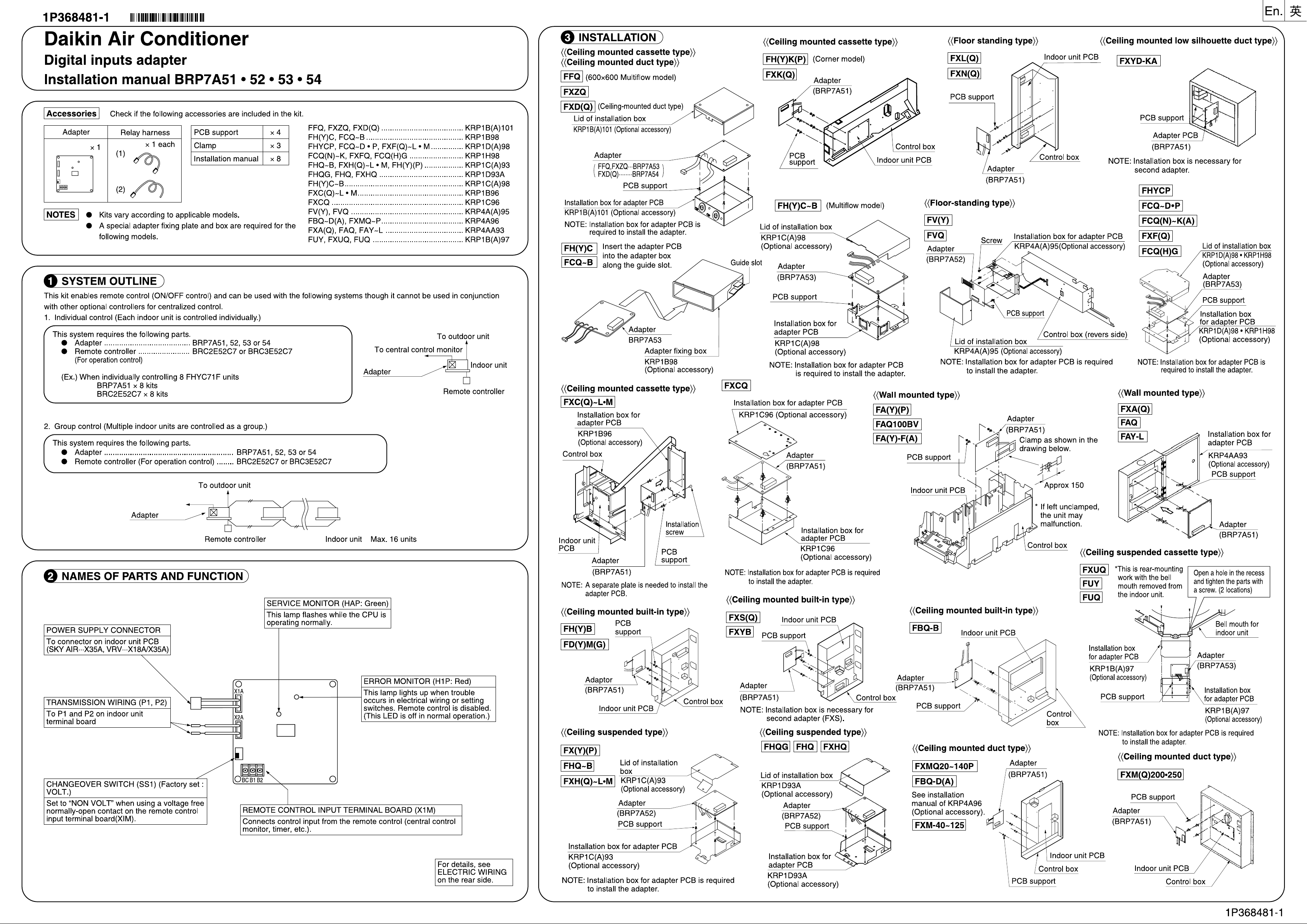
Daikin BRP7A51, BRP7A52, BRP7A53, BRP7A54 Installation manuals
En.
4 ELECTRIC WIRING
1
First, do the wiring between the indoor and outdoor units, then to the separate power sources and finally
between the indoor units and the remote controllers. Next, check if they operate properly.
(When using for group control by a remote controller, avoid cross wiring.)
For details, see the installation manual of the indoor and outdoor units.
Next, do the wiring between outside units such as the central control monitor and adjust the necessary settings.
2
For details, see Wiring to outside units (central control monitor) .
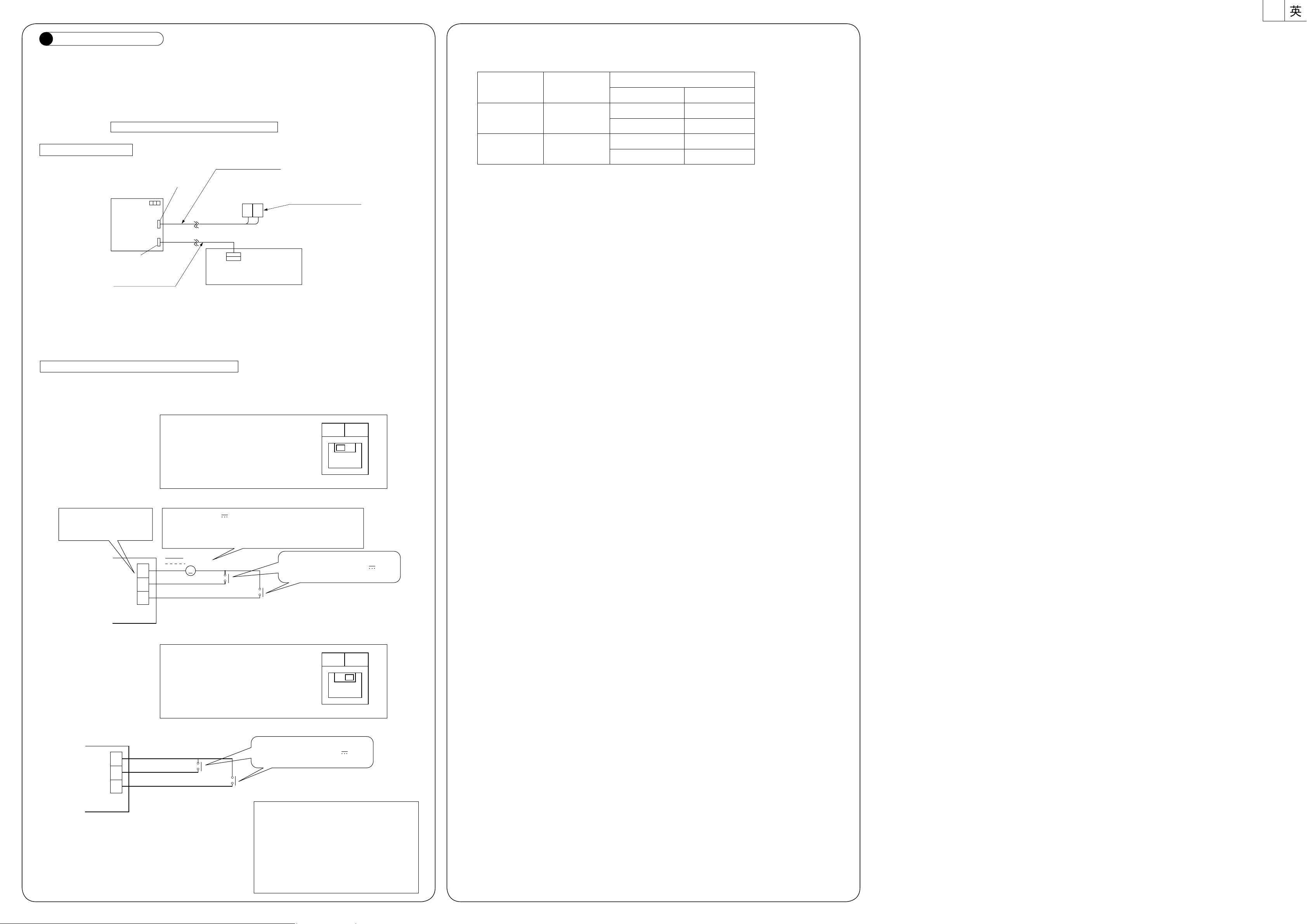
Wiring to indoor units
Adapter
Blue
× 2A
× 1A
White
Relay harness (2)
Transmission wiring
terminal board
P1 P2
X35A (SKY AIR)
X18A/X35A (VRV)
2. External input logic (for interlock function of hotel room)
Connect the external inputs in accordance with the following specification.
Connection specification of External inputs
External input logic
Control terminal
B1/BC
B2/BC
Input name
Input A
Input B
Status
Windows CLOSE
Windows OPEN
Key Card IN
Key Card OPEN
Contact State
close
open
close
open
Relay harness (1)
Indoor unit PCB
Perform the connections as shown above, using the attached relay harnesses (1) and (2).
● Connect relay harness (1) to the connector (X35A or X18A) on the indoor unit PCB.
● Relay harness (2) has no polarity. Connect it to terminals P1 and P2 on the transmission wiring terminal
board inside the indoor unit Electric parts box.
Wiring to outside units (central control monitor)
1. Remote control input (operation control)
Do the wiring as described below. Wiring differs depending on whether a voltage or no-voltage input is used.
NON
VOLT
For voltage input
Set the changeover switch (SS1) to
“VOLT”. (Factory set : VOLT)
VOLT
Connect the control input
to the common contact
(no polarity).
BC
B2
B1
For voltage free contact input
Use an external 12 - 24 V power supply. Each contact
requires approximately 10 mA, therefore carefully select
the power supply capacity. Power supply is connectable
without regard to positive or negative.
12-24V
G
Input B
Use a small voltage contact of a
minimum current load of 12 V,
1 mA or less.
Input A
NON
VOLT
Set the changeover switch (SS1) to
VOLT
“NON VOLT”.
BC
B2
B1
Input B
Input A
Use a small voltage contact of a
minimum current load of 12 V,
1 mA or less.
(Wiring specifications)
Wiring … Sheathed vinyl cord or cable
Wire size … 0.18 - 1.25 mm
2
Length … Max. 150 m
〈NOTE〉
Keep transmission wiring away from power
supply wiring to avoid malfunctions.
1P368484-1
 Loading...