


DAIKIN
INSTALLATION
MANUAL
R410A SPLIT SERIES
<INVERTER>
MODELS
ATXN2SMV187
ATXN3SMV187
ATXNSOMV187
ATXN60MV187
ATXN2SNV18
ATXN3SNV18
ATXNSONV18
ATXN60NV18
ATXN20MV16
ATXN2SMV16
ATXN3SMV16
ATXNSOMV16
ATXN60MV16
ARXN2SMV187
ARXN3SMV187
ARXNSOMV187
ARXN60MV187
ARXN2SNV18
ARXN3SNV18
ARXNSONV18
ARXN60NV18
ARXN20MV16
ARXN2SMV16
ARXN3SMV16
ARXNSOMV16
ARXN60MV16
Cepll1R
R410A c pa3,QeJlbHOIiI
In
stallation Manual
R41
OA
Split Series
Manuale d'installazione
Serie Multiambienti
In
stallationsanleitung
Split-Baureihe
Manual de instalaci6n
Serie Split
Manuel d'installation
Serie split
Mo
ntaj kylavuzlary
R41
PYKOBO,QCTBO no MOHTa>K)'
R41
OA
R41
OA
R41
OA
R41
OA
OA
Split serisi
YCTaHoBKoliI
English
Italiano
Deutsch
Espanol
Franc;ais
Turkc;e
PYCCKIiIM
~H[
(Applicable to cenified models only)
IM-5WMYJR-1113(4)-DAIKIN SIESTA
Part Number.: ROa019039397D


OUTLINE
AND DIMENSIONS
Indoor
Unit [ATXN]
TIlE MARK (
~
) S
HOW
S PIPING DIRECTION
A
RIGID
-
c
TOP
VIEW
-
t--
SIGNAL RECEIVER
j
c-_~~~~~~~~~~~~~~~~~~
BOTTOM.
LOUVER
FRONT
(INSIDE)
GRilLE
AXED
BOTIOM
SCREWS
___
INDOORUNITT
ON
t
ROOM TEMPERATURE TIIERMISTOR
(INSIDE)
FRONT VIEW
/OFF SWITCH
::::
"---
SIDE VIEW
rrc
NAMEPlATE
r--
TERMINAL
r---
BLOCK
WITHEARTII
TERMIN
AL
NOTE: PLEASE BASED
20125/35 DIMENSION REFERENCE AT PAGE 1 &
* Reco
mmended
(5 spots in all)
ON
ACTUAL INSTALLATION PLATE DESIGN IN
mOllming plate retention
spo
o
Liquid pipe
ts
~"lT-
cnd
INSTALLATION
2.
PLATE
Usc
tape
Position
Gas
pipe
mea
we
end
cnd
20/25/35
TIlE
UNIT
sure as shown.
of
a tape measure at
FOR
INSTALLATION PLATE
..
lbrough
hole
065nun
the
wall
~n
Model
20/25/35 MV
25/35
NV
A B C D E F G H I
800
859
288 212
288 209
166
166
184
184
42 46
42 46
55
55
I-I
J
56
154
56
154
All dimensions are
K L M
182
263
182
263
in
52
52
mm

D
.//
'@
l.
_____________
H
"
__
*
Reconunended
(5 spots
in
"'
___ ~ ___
!-
__
"1_
L M
mOllming piate retention spots
all)
••
A
E
lbr
ough the wall
hole
tIr
65mm
i
_J
~
Drai n ho
se
K
position
~n
Model
20/25/35
25/35
NV
* Re
(7 s
MV
conmle
pot
s in all)
~
I
ndcd mo
\ D
A B C
800
859
unting
piate retention spots
\
\.
-
""
,
.,-
Liquid pipe end Gas pipe
ALTERNATIVE
D
288
212
10
288
209
10
,
I' ·'n ., ,' I
end
INST
AUAllON PLATE
E F G H
4
141
4
141
I'
· ' ' ·
30
30
46
46
'j)'
20125/35
55
55
I ' I
All dimensions are
I
J
1
56
56
E
i
53
1
53
N/"
in
K L M
181
207
181
207
~
I
...,..-Through the wall
hol,
065mm
mm
52
52
~n
Model
50/60
MV
50/60
NV
tH
~~~
J
~==
A B C D E F G H I
10
65 310
11
24 3
\l
'"
L
~
[j
~qlli~-d="~-"~'~"
10
d
==
~
~M~_
L~:~
~
_"~
-
"~'~"d
INSTAUATION
228 190
237 190
173
173
1·
2
____
PLATE SO/(JJ
61 40 45 48 91 219
61 40 45 48 91 219
~~
-=-=-=~
"K
====:
~:
I
j
~
All dimensions are
J
Drain
ho
se position
in
mm
K L M
580
580
45
45

Outdoor
Unit
[ARXN]
~n
Model
20/25/35
~
J
r-
H I
'"
t:l
1::1
1:1
51
II
'"
273
E F o B c
A B C D E F G H I
550
658
L K L
cl
I tI
I
I
\i
I
16
14 470
1
hi
1:
1
~
.,
J
96 93
20
1
All dimensions are
o
K L M N 0
94
60
14
133
All dimensions are in mm
in
p
8 W
mm
Q
299
~n
Model
50NV
60
NV, 50/
60
3.0
MV
I
I
I
~~
I
Q
20T
LJ
LJ
LJ
['
l
A B C D E F G H I
855
628
328
520
179
46
93
149
855
730
328
520
179
46
93
149
~L
"'
J
WI
113 603 126
WI
113 603 126
c
G H
a
•
•
T
K L M N 0
164
164
15 34
15
34
~n
Model
60
NV, 50/
50NV
60
MV
p
23
23
Q
R S T U
362
73
362
73
75
75
V
8
67
7
8
67
7
1-
3

Tills
mannal
S
pecial
Before using
Tills appliance
persons.
Tills
experience
for
their s
C
hildren shOlild
• Insta
perso
experienced
• All
wiri
• Ensure that
the
the
• The
to insulation fai
•
All
movi
• Con
or
•
Risk
remain
•
DO NOT
may
fire hazards.
• K
wiri
pictures
electrical
1m
provid
adjustment may
your air
is
intended
appliance
servicing the
eep
is
1I0t
and
knowledge, unl
afet
y.
be s
lla
tion and maintenance
ns who
are
with
field wiring must be installed
ng
regulation.
the
name plate
wiri
ng
diagram.
Imit
must
be
electrical
finn that
ng,
away
ng
parts
of el
ectric
electric
plill
cause seri
the
indoor
at
least
and static
waves, static
}.
wiri
of
the unit
out the
INSTALLATION MANUAL
es
the
procedures of inst
be
nec
ess
conditi
intended
upervised
Lh
WARNING
familiar
this
type
rated
voltage
before
GROUNDED
lure
.
ng
must not
the fan
has
unit.
shock, can cause injury
power supp
power cord when
ous
electrical
and
outdoor
1m
from TVs
. {Depending
ary
oner,
plea
to
be
use
for use by
ess
they have
to ens
shou
with
local
of
appliance
in
of
the
commenci
ng wiri
to prevent
touch the
motors.
been
switc
lies
before
shocks which may result
Imi
ts,
and
on
may
be heard
allation
to suit loc
se
d by
ure
al
read this instruc
expert
or
person
s,
been
given supervision
that
they do
SAFETY PRECAUTIONS
ld
be
perfonned
code
and
regulation
.
accordance with th
unit
corresponds
ng work
possib
water piping or any
hed
OFF
before installi
or
deat
h. D
servicing.
the
power is
power
cable
radios, to preve
the
and
type
and
even when
to ensure a safe
requirement.
tion
tra
ined
users
including
by
accordi
le
iscOimec
transmission
nt
source
not play
qualified
, and
e n
ati
ona
to
that
ng
hazard
due
ng
t a
ON.
Thi
in
the
distorted
of
the
more than
children, with
of
to
ll
Ulallllal
in shop
or
with
l
s
and
good standard
carefully and
s,
ill
light
reduced
instruc
tion
the
appliance
Plea
se take
installing.
•
Do
not ins
occur.
'"
\.y
• Ens
ure
O
•
Do
uot
o O
• Eusure that the unit's
installation.
o
• Sharp
ma
y cause injury
these
• Before turning
controller
the nuis
fans
will
a
hazard
•
Do
not insta
Do
not
•
conditioner
or
oil steam
deform
•
When
into suction
•
This unit
mist
•
Do
not ins
plant
• Ensurethecolorofwires
markin
• IM
PORTANT:
C
ONDITIONER UNIT
•
Don
s
uppl
The
•
explosive atmosphere
of
keep
industry
physical, senso
con
cerning
.
note
tall
If
gas
leaks
fire
ignition.
that draina
If
the
drainage piping
cause
water
overcharge
This Imit
vercharge will
compressor.
Unsecured
edg
es
and
place
s.
's ON/
ance
tripping
start
hmling
to
service persomlel
ll
operate any hea
unit
exi
as a res
the
unit
of
is
not suitable
or
iron
powder exist or
tall
where sulphide gas
gs
are s
't lise joined
y.
equipment is
operation
it
and
Lh
of
the
is
panels w
OFF switch
the
or use
st,
ult
is
used
the
the
ame
DO
for
the
for
future
referen
011
farm
s,
or
ry or
use
oCtile
ment
appliance
CAUTION
the
following
unit
where
leakage
and
accumulates
ge
piping
leakage
the
unit.
factory pre-charged
calise
coil
surfac
hazards.
off
the power suppl
of
automatically when
uni
ts
in
this
of
exc
in
unit.
units at
to
the
NOT INS
and
not
.
arOlmd
is
connected
is
not
which
will
over-current or d
panel
is
ill
cause
es are
Avoid
to
the
the
unit.
or the
at
or near
ting
apparatllS
room
where
may callSe plas
ess
ive heat
kitchen, keep
for
factory
volta
area
like
exist
s.
of
the
outdoor
indoor
TALL
IN A LAUNDRY
twisted
wires for
intended
air conditioner
ce.
for commercial use
al capabiliti
by a
important points
ofnammable gas may
the
connected properly, it
dampe
.
closed
the un
it
potenti
from
being
y,
''OFF''
If
this
is n
power
use
r.
doorwa
to'o
mineral
tic
or
chemical
flour
llSed
ge
fluctuat
hot
spring
unit
s respectivel
OR
for use
unit.
es,
or
pe
rso
n responsible
Imit, it
may
properl
y.
n the
fumiture.
amage
after service or
to
operate noisily.
al
locations which
in
contact
set the remote
position
to
ot done, the
resmnes, posing
y.
clo
se
to
oil, oil
part
to
reaction.
away from
where
cutting
es
greatly.
or
oil
refinery
and
the
tenninal
y.
USE
THE
ROOM
.
incoming
in
a potentially
by
la
lack
when
calise
may
to
the
with
prevent
unit'
the
air
vapour
melt
or
going
oil
AIR
power
y
of
s
Disposal
Your air
un
Do
other parts
Air con
disposed
the
Batteries
legislat
requiremen
conditioning
sorted household
not
try
to
must
ditioners
of
correctly,
installer
or
must be removed from the
ion.
ts
product
waste.
dismant
le
the
be
done
by a qualified
must
be treated
you will
local authority for
is
marked
system
yourself:
at a specialized
help
more infonnatio
to
prevent
remo
\vith
this symbol. This
the
dismantling
installe
r in
accordance with
treatment facility
potential negative con
n.
te
controller
NOTICE
means
of the
and
dispose{)
that
elec
air con
ditioni
relevant
local and
for re-
use
sequences for
of
separate
1-4
tri
cal
and electronic
ng
system, treatment
national
, r
ecycli
ng
and
the
environme
ly in
accordance
products sha
of
the refri
legislation.
recovery. By
nt
and hum
wit
h r
ll
not
gerant, of
ensu
ring
an
health. Please con
elevant
local and
be
mixed with
oil
this
product
national
and
of
is
tact
-

IMPORTANT
Important
TItis product contains
Do
not vent gases into the atmosphere.
Refrigerant
GWP
(I)
GWP
Please fill
•
<D
information
type:
R410A
(I)
value: 2087.5
= Global
the factory refrigerant charge
Wanning
in
with indelible ink,
regarding
flu
orinated greenhouse gases.
Potential
the
refrigerant
of
the product,
used
• ® the additional refrigerant amount charged in the field and
•
<D
+ ® the total refrigerant charge
on
the refrigerant charge label supplied with the product.
ftlled out label must
TIle
W
onnw.lld,.......
1
8410A
I
<D=
, ,
(2)
In
case
of
mnltiple indoor systems, only I label must
indoor units connected in the refrigerant system.
Periodical inspections for refrigerant leaks
local dealer for more infonnation.
*
on
the outdoor unit
...
r------'
be
adhered in the proximity
1 factory refrigerant charge
•
s
ee
k9
unit name plate
2 additional refrigerant amount charged in the field
3 total refrigerant charge
4 contains fluorinated greenhouse gases
5 outdoor unit
6 refrigerant cylinder and manifold for charging
may
of
the product charging port (e.g. onto the inside
(2)
be
adhered*, mentioning the total factory refrigerant charge
be
required depending on European
of
the product:
of
the service cover).
or
local legislation. Please contact
of
your
all
1-5

I
Indoor
Unit
SOmm
or
more
(on both sides)
Air
filler 0
gK
I
Outdoor
INSTALLATION DIAGRAM
M.:'m
-;:=----
Unit
S.~;"l;d
•
Opening
5enice lid
Service lid
is
closing
•
Opening
I) Remove
2)
3)
opening!
type
method
the
0111
the
service lid
of
the
service lid
screws
pun
diagonally down
dllection
PuUdown
in
arrow
the
Where
a wall
or
below.
For
any
of
I Wall facing o
More wauSO More
other obstacle is
the below installation patterns, the wall height on the exhaust side should
ne
side Wall facing two sides
c::;
1200
less
I
Side View Top View
INSTALLATION
in
the path
than
100
I
or
rc-
~
I
OF
THE
of
outdoor unit's intake
More
OUTDOOR
or
than
50
Wall facing three sides
UNIT
exhaust airflow, follow the installation guidelines
be
1200mm
or
More
less.
th~
150
I
w
D
More
than
50
1-6
Top View
Unit:
nun

Drain
work.
(Heat
Pump
Unit
Only)
1) Use drain plug for drainage.
If
the drain port is covered
2)
additional foot bases
unit's feet.
3)
In cold areas, do not use a drain hose with the ontdoor unit. (Otherwise,
drain water may freeze, impairing heating perfonnance.)
by
a mOllllting base or floor surface, place
of
at least 30mm in height under the outdoor
Bottom frame
Drain
Plug
Hose (available comercially,
innerdia.l6nun
)
INSTALLATION
TIle ontdoor unit must be installed in snch a way, so as to
of
prevent short circuit
the smooth air flow.
shown in the figure. Select the coolest possible place where
intake air temperature is not greater than the outside air
temperahrre (Refer to operating range).
the hot discharged air or obstruction to
Please follow the installation clearances
OF
Installation clearances
Dimension
Minimum Distance, mm 300 1000 300
Note:
If
there
is
any obstacle higher than half,
(II)
height
in the above table.
, please allow more space than the figure indicated
A B C D
SOO
of
the unit's
THE
OUTDOOR UNIT
g
]
0
B
-.
•
E
€I
~
(>
o
Condensed
(Heat
TIlere are 2 holes on the base
water to flow out. Insert the drain elbow to one
holes.
To install the drain elbow, first insert one portion
hook to the base (portion A), then pull the drain elbow in
the direction shown
portion to the base.
the drain elbow clings to base finnly.
If
the unit
water may freeze in the base. In such case, please remove
plug at the bottom
Water
Disposal
Pump
Unit
Only)
by
Mter
is
installed in a snowy and chilly area, condensed
of
Of
Outdoor
of
Outdoor Unit for condensed
the arrow while inserting the other
installation, check to ensure that
unit to smooth the drainage.
Unit
of
of
the
the
BASE
1-7
~
CJ
A
~
~llll
l
PLUG
-
'-1,1114'1
11
DRAINELBOW
DRAIN ELBOW
+---111-
"f''4-I
---'!!!fI
Please remove side
1--
plate when cOlUlecting
.}~
the piping and
COlUlecting
&
cord
PULL
UP

INSTALLATION
OF
THE
INDOOR UNIT
The indoor unit must be installed in such a way
short circuit
Please follow the installation clearance shown in the figure. Do
not place the indoor unit where there could
shining
and
of
the cool discharged air
on
it.
Also, this location must
drainage, and
min. 50
(Space for
mainte!lallct")
be
away from doors
'-"
ReqUired space
All dimensions
so
as
to prevent
with
the hot renIDl air.
be
direct sunlight
be
suitable for piping
or
windows.
min. 50
(Space for
maimenanct')
are
in
mm
The
refrigerant piping
of
ways (left
cut-out holes
pipes carefully to the required position in order to align it with
the holes.
piping and then position it to the required direction (see fignre).
The
condensation drain hose can
Right-side, right-back
Right side piping
Wemo
here:
Left-side, left-back
or
on
For
the side
..... e pipe:
pon cover
for right-side: piping
can
be
right from the
the casing
of
and
bottom ant, hold the bottom
or
---'
l
Right-bottom
piping
Wemove
pipe:
here
pon cover g I
for right-bottom piping
or
left-bottom piping
routed to the unit in a
back
of
the unit) ,
the unit (see figure). Bend the
be
taped to the pipes.
right-bottom lliping
by
using the
number
of
the
~
~
R;,h,~oo,kpipin,
tape:.
pipe:
pipe:
pon
Bind coolant
and drain hose
together with
insulating
Remove
cover here for
left-side piping
Mounting
En
sure that the wall is strong
of the unit. Otherwise. it is necessary to reinforce the wall
with plates, beams
Use the level gauge for horizontal mounting, fix it with
5 suitable screw s for
50/
60.
In
case
diameter with a cone drill, slightly lower
(see figure).
20f25f35
Installation
the
rear
or
pillars.
piping
Plate
enough
20125/35
draws
to withstand the weight
and 7 suitable screws for
out, drill a
hole 65mm
on
the outside wall
in
\Il~~~~~~~~~~~r~~E
Remo
..... e pipe:
here:
20f25f35 (ALlERNATIVE INSTALLATION PLATE)
~ fixing screw
50
f60
pon cover Left-back piping
for left-bottom piping
Left-bottom piping
~
~
\/
~
MO=
""",
'.
/"
__
'N
Mounting plate
Left-side: piping
~
",,-
Pl"'
~
Mounting plate
(~~
Mounting plate fixing screw
I
Mounting plate J
flXing
1~8
screw

Recommended
Dimen
sion s
20/25/35
t
RecommeOOed
tetentioo.pOlS
tnOU1Iting
(5 spots
Mounting
pt:.te
in
all)
Plate
Retention
Use tape measure as
Position the end of a tape measure at
All
diml'n
SOO"'lI
sions
Spots
are
in
And
~
mm
Mount
The Unit
Onto
The
Installation
Plate
Hook the indoor unit onto the upper portion of the installation
plate (Engage the two h
with the upper edge of the installation plate). Ens
hoo ks are properly seated on the installation plate
oo
ks at the rear top of the indoor unit
ur
e that the
by
mov ing
it to the left and right.
How
To
Attach
The
Indoor
Unit
Hook the claws of the bottom frame to the mounting plate.
How
To
Push up the marked area (at the l
Remove
The
Indoor
Unit
ower
part
of
the front grille)
to release the claws .
20/25/35 (ALTERNATIVE INSTAllATION
t
R=
......
ndrd
IIIOUIlIint
I
pipe eDd
plair
All
All
(S
spOOl
",:ill)
Uquid
pipe eDd
G~
50/60
t
RI'COllllliE'llded
(7 spots
o~'
mounting
in
all)
plate retention spots
'.~~
4.1
91
Hole With Cone Drill
Inside
Wall
embedded pipe
(Field supply)
......
PLATE)
R:lrntiao
spOOl
dimensions are in
diml'nsions are
Outside
Caulking
in
mm
mm
Mark
Fro nt grille
When str
ends
of
interconnecting
wires
in advance,
right ends
insulating tape.
Water
Drainage
ipping
of
wires with
Hang in
the
bind
Piping
door unit' s hook
Wire guide
here.
(rear side)
Momning plate
TIle indoor drain pipe must be in a downward gradient f
smooth drainage. Avo id situations that are likely to cause
water to leak.
Water Drainage
••
w
Retention
Wa~
leaking •
Wrong
End dipped
mto
water
Drai n
(2)
Corrw
Wa~
leaking'
@ @ @
W=,
Wrong
or
Wall
hole
cover
(Field supply)
Lh
CAUTION
• Do not install the unit at altihlde over 2000m for both
indoor and outdoor.
1-
9
REFRIGERANT
PIPING
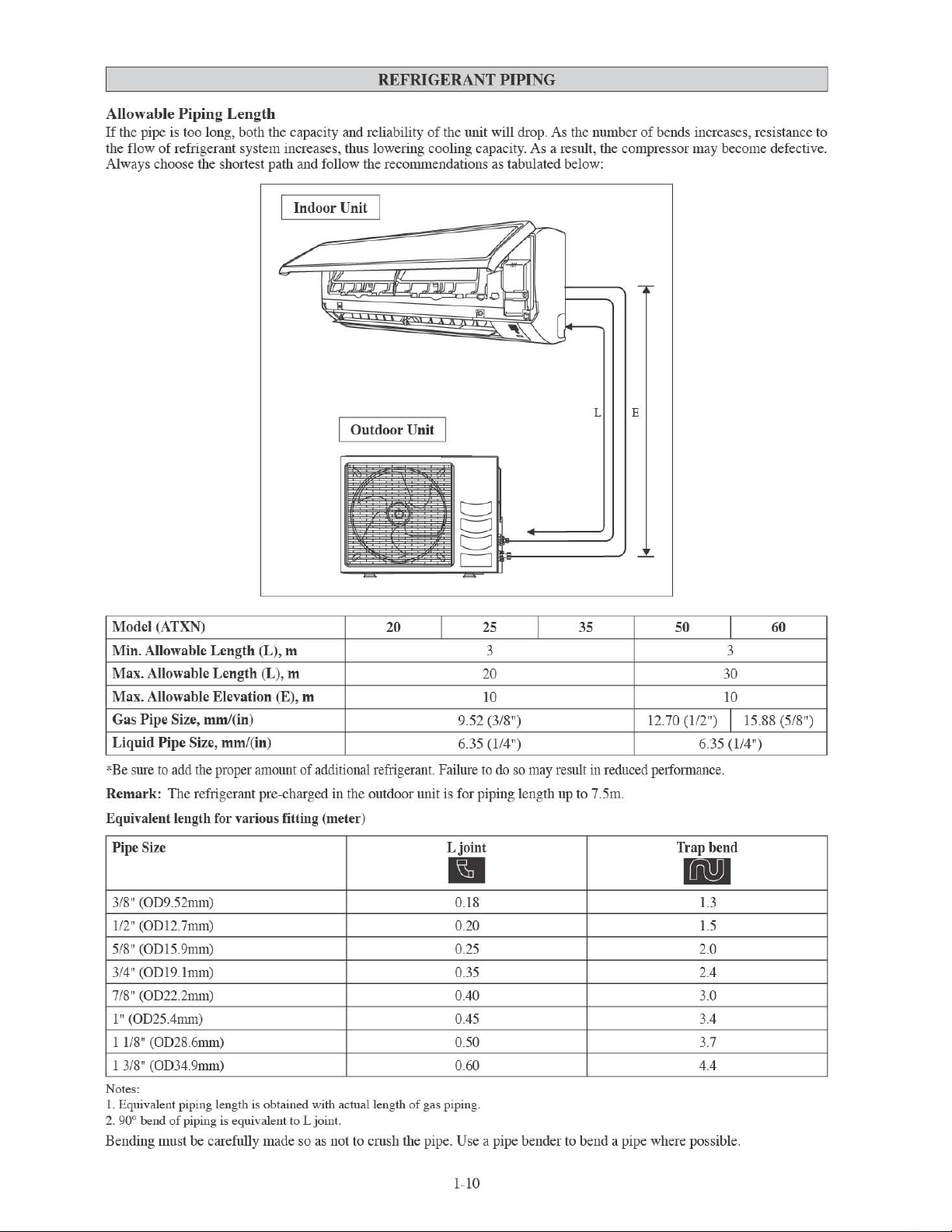
Allowable
If
the pipe is too long, both the capacity and reliability
the fl
Always choose the shortest path and foll
Piping
ow
of refrigerant sys
Length
tem
increases, thus lowering cooling capacity.
I Indoor Unit
ow
the recommendations as tabulated below:
Outdoor Unit
of
the unit will drop .
As
the
number
As
a result, the compressor may become defective.
of bends increases, resistance to
E
Model
(ATXN)
Min.
Allowable
Max.
Allowable
Max.
Allowable
Gas
Pipe
Liquid
Pille
"'
Be
sure to
Remark:
Equivalent length for
Pipe
Size
3/8" (OD
1/2" (ODl2.7mm)
5/8" (ODl5.9mm)
3/
4" (ODl9
7/8"
(OD22.2mm)
1" (OD25Anlln)
1 1/8" (OD28.6mm)
3/8" (OD34.9mm
1
Notes:
1.
Equivalent piping length is obtained with
90° bend
2.
Bending mnst be carefully made
Length
Size,
mml(in
Size, mml
add
the proper amou
TIle refrigerant pre-charged
9.52mm)
.1mm
)
of
piping is equivalent to L joint.
(L), m 3 3
Length
Elevation (E)
various
)
(L), m
)
(in)
, m
nt
of additional refrigerant. Failure
fitting (
so
20
in
the outdoor unit is for piping length up to 7.5m.
meter)
acntallength
as
not to
of
gas piping.
cmsh
the pipe. Use a pipe bender to bend a pipe where possible.
25
I
20
10 10
9.52 (3/8")
6.
35
(114")
to
Ljoint
•
0
.18
0.20
0.25
0.35
O
AO
O
A5
0.50
0.60
do
so may res
I
35
12
ult
in
reduced perfonnance.
50
.70
(1
/2") I
6.
Trap
11.1
1.3
1.5
2.0
2A
3.0
3.4
3.7
4A
30
35
(114")
bend
I
15.88 (5
60
/8")
1-10
REFRIGERANT PIPING
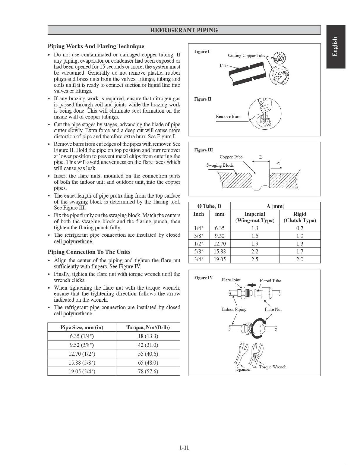
Piping
Piping
Works
Do not use contaminated or damaged copper tubing.
any piping, evaporator or condenser had been exposed or
had been opened for
be vacuumed. Generally do not remove plastic, mbber
plugs and brass nuts from the valves, fittings, hlbing and
coils until
valves or fittings.
If
any brazing work is required, ensure that nitrogen gas
is passed through coil and joints while the brazing work
being done.
is
inside wall
Cut the pipe stages by stages, advancing the blade
cutter slowly. Extra force and a deep cut will cause more
distortion
Remove burrs from cut edges
Figure II. Hold the pipe on top position and burr remover
at lower position to prevent metal chips from entering the
TIus will avoid unevenness on the flare faces wluch
pipe.
will cause gas leak.
Insert the flare nuts, mounted on the connection parts
of both the indoor
pipes.
TIle exact length
of
the swaging block is determined by the flaring tool.
See Figure III.
Fix the pipe fmuly on the swaging block. Match the centers
of
both the swaging block and the flaring punch, then
tighten the flaring punch fully.
TIlC refrigerant pipe connection arc insulatcd by closed
cell polyurethane.
Connection
Align the center
sufficiently with fmger
Finally, tighten the flare nut with torque wrench until the
wrench clicks.
When tightening the flare nut with the torque wrench,
ensure that the tightening direction follows the arrow
indicated on the wrench.
The refrigerant pipe cOimection are insulated by closed
cell polyurethane.
And
Flaring
it
is ready to connect suction or liquid line into
lltis
will eliminate soot fonnation on the
of
copper hlbing
of
pipe and therefore extra burr. See Figure I.
mut and outdoor mut , into the copper
of
pipe protmding from the top surface
To
of
the piping and tighten the flare nut
Technique
15
seconds or more, the system must
s.
of
the pipes with remover. See
The
Units
s.
See Figure
IV.
of
If
pipe
Figun'" I
Cutting Copper Tube
1I4'
~\Y;::
~
" '
.;','
, .
----
~
Figun'"
II
Remove
Burr
Figun'"
III
CoppcrTube
sw"m_l1~
,
o Tube, D A
Inch
114"
3/8" 9.52 1.6 1.0
112"
5/
3/4" 19.
Figun'"IV
mm
(Wing-nut Type)
6.35
12.70 1.9
S"
15.SS 2.2 1.7
05
Flare Joint
~~
Indoor Piping Flare Nut
0
~!
(mm)
Imperial
(Clutch
1.3
2.5 2.0
flared
Tube
Rigid
0.7
1.3
,
Type)
Pipe
Size,
mm
(in)
6.35
(114")
9.52 (3/S") 42 (31.0)
12.70 (112")
15.SS (5/S") 65 (4S.0)
19.05 (3/4")
Torque,
NmJ(ft,lb)
IS (13.3)
55 (40.6)
7S
(57.6)
~
I-ll
ELECTRICAL
WIRING CONNECTION
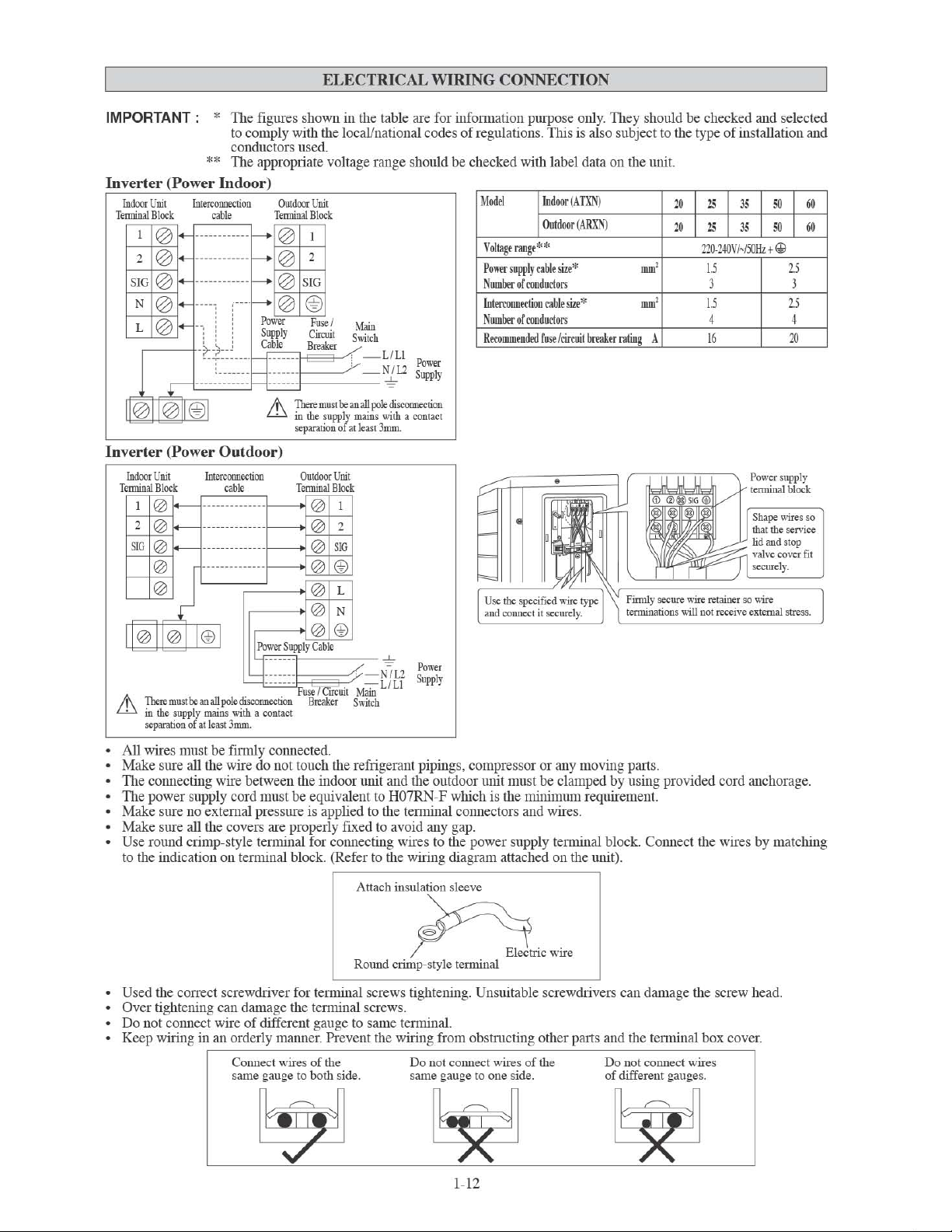
IMPORTANT: *
**
Inverter
Terminal
(Power
Indooc
Unit
Interconnection
Bloc
k
cable
1
2
SIG
N
L
------------
@ @
------------
@
..........
@
@
@
--
I
~L
~
....
--'-
II@II@II@I
Inverter
Terminal
ill
(Power
hxIoor
Unit
Block
1 @
2
@
51G
@
@
@
II@II@
n..
Th=mustbcanallpokdisconncctJoo
in
the
separation
~
~
~
j
supply
of
I
nterconnection
------------
--------------
--------------
-------------
I@I
mains
at
kast
The figur
to comply
conductors used.
Th
Indoor
i.
........
~~~~~~~~
es shown
wi
e appropriate voltage range should be checked with label data on the unit.
in
th the local/national codes of regulation
the table are for
infonnati
on pu
rpose
onl
s.
TItis is also subject to the type of installation a
y_ They
)
fum(A
**
Out
ble
rablt
fnst
doo
r (
sizt*
sizt
l
cirruit
TXN)
ARX
*
break
N)
Outdoor
Unit
Terminal
Block
~
~
_-
~
~~~
Power
Supply
EB"""
1
2
@
@
SIG
@ @
F~
I
M.m
Cirruil
S\\1tch
of
at
LlLl
N 1
~
pole
with
kasl 3mm
-------
~~~~~~~
6
~~:'7y~ns
separauon
""~
12
Supply
disconncct:ion
a contact
ll
OOcl
VoHag
t
range
Po
Wl'r su
Nu
mber
of
Inte
rronn
Number
or
R
erommtnded
pply ca
rondnclors
ect
ion
rondnclors
Outdoor)
OuiOOor
Unit
Terminal
"b'
--
-----<
-----<
-----<
-----<
Block
@ 1
@ 2
@
51G
@ @
@
L
@
N
@ @
Power
Supply
Cable
Fuse
i C
Breaker
iiC
uit
<'
Main
Switch
N 1
LfLi
12
Power
Supply
with
31IU1L
.......
.......
.......
a contact
should
mm
'
mm
'
er
raling
A
Finnly secure ",ire
tcnuinations will
be
checked and selected
-,
l<I
l<I
1<
'"
-,
1<
'"
220-240
VI~I
50Hz t~
1.5
3 3
1.5
4 4
16
Power supply
j--,=
Shape
that the service
lid and stop
valve cover
seeurdy.
re
taioer
so
receive ex
",ire
tCTllilI stre
00{
"
"
,;",I
15
25
2Il
block
",ires
nd
OJ
OJ
so
fit
ss.
All wires must
Make sure all the wire do not touch the refrigerant pipings, compress
Th
e connecting wire betwe
The po
wer supply cord must
Make sure no exte
Make sure all the covers are properly fixed to avo
U
se
round crimp- style tenninal for c
to the indication
be
finlll y connected.
en
mal
press ure is appli
on tennin
al block. (Refer to the wiring diagram attach
the indoor unit and the outdoor unit must be clamped by using provided cord anchorage .
be
equivalent to H
ed
Oime
07RN
to the te
cting wires to the power supply te
Attach insulation sleeve
-F which is the minimum requirement.
nnin
al connectors and wires.
id
any gap.
n
Used the correct screwdrive r for te
Over tightening can damage the te
Do not co
Keep wiring
nn
ect wire of different gauge to same te
in
an orderly maIme
Connec
t wires of the
same gauge to both side.
Round crimp-
nmn
al screws hghtening. Unsllltable screwdrivers can damage the scr
nnin
al screws.
r.
Prevent the wiring from obstmcting other parts and the tenllinal box cove
sty
le temun
al
nnin
al.
Do not connect wires
same gauge to one side.
1~1
2
or
or any movin
nnin
ed
tri
ow
of
the
al block. Conn
on the unit).
rr
,
g parts.
Do not connec
of
different gauges.
ect the wires by matching
ew
head.
r.
t wires

SPECIAL PRECAUTIONS
R410A
is a new HFC refrigerant
ozone laye
1.6 times
proper installation
r.
The
working pressure
lilgher tllan conventional refrigerant (R22), thus
/se
rvicing is essential.
Never use refrigerant other than
which is
POE
which
de
signed to operate witll R41OA.
or
PYE
oil is used as lubricant for R41
is
different
from
compressor. During installation
must be taken not to expose tile
to moist air. Residual
components can absorb moisture from tile air.
To pre v
ent mischarging, the diameter
on tile flare valve is different from that
POE
which
does not damage the
of
tlils
R410Ain
the
mineral
or
servicing, extra precaution
R410A
or
PVE
oil
new
refrigerant is
an air conditioner
0Aco
oil use
system t
in
tile piping and
of
tile service port
of
R22.
WHEN
mpressor,
d f
or
R22
oo
long
DEALING
Use tools
Tools exclusively for
ho
se, pressure gauge, gas leak detector, flare tools, torque
wrench, vacuum
As
an
than
R22
correctly.
If
the refri gerant gas leakage occurs during installation/
servicing , be sure to ventilate fully.
comes into contact with fire, a poisonous gas
When
allow air
VACUUMING AND CHARGING
Vacuuming is necessary to eliminate all moisture and air from the system.
Vacuuming
Except
refrigerant , the indoor unit and tile refri gerant connection
pipes must be air-purged because tile air containing moisture
that remains in tile refrigerant cycle may cause malftmction
of
the compressor.
Remove
Connect the center
pump.
Connect the charging gauge to tile service port
valve.
Start tile vacuum pump. Evacuate for approximately
nilnutes. TIle evacuation time varies with different vacuum
pump
mov
Caution
If
tile gauge needle
to
check
and outdoor
tile next step.
Close the valve
pump.
On
liquid valve (2 way) (in anti-clockwise direction) with
ke
y for hexagon sacked screw.
Charge
TIils operation must
precise weighing machine.
into the outdoor
port.
Remove
Connect tile
suction service port center
tile
service
Start tile air conditioner unit.
Open tile gas cylinder
When
tile milt, close the
valve.
Disconnect the service
tile service port cap.
The
for
the outdoor
Piping
And
unit
The
which
Indoor
is
pre-charged
Unit
with
the caps from the valve and tile se rvice port .
of
tile charging gauge to tile vacuum
of
tile 3-way
30
capacity.
ed
Confmn
tllat the charging gauge needle has
towards -760mmHg.
doe
s not move to -
760
mmHg, be
sure
for leakage at flare type connection of the indoor
milt and repair the leak before proceeding to
of
tile changing gauge
tile outdoor milt,
open
tile suction valve (3 way)
and
stop the vacuum
and
4mm
Operation
be
done
by
using a gas cylinder and a
The
milt nsing the suction valve via tile service
the service port cap.
low
pressure s
lilgh pressure side of the gauge. Purge tile air from tile
ho
se.
the required refri gerant quantity is
low
additional charge is topped-up
ide
of
the charging gauge to tile
of
the cylinder tank and
and
low
pressure charging valve.
pumped
pressure s
ho
ide
and the gas cylinder
se from service port. Put
clo
into
back
se
,----------------------,
WITH
and
R410A
R410A UNIT
materials exclusively for refrigerant R41OA.
R410A
are manifold valve, charging
pump
and
refrigerant cylinder.
air
conditioner
incurs
higher
units, it is essential to choose the
If
the refrigerant gas
installing
or
rem
oving an air conditioner,
or
moisture to remain in the refrigerant cycle.
lUGH
LOW
PRESSURE GAU
GE
VALVE
PRESSURE
CO!'.'HGURATION
PURGE
lUGH
PRESSURE
CO!'.'HGURATIO:-.l
PURGE
HOSE
pressure
copper
may
GAUGE
OIECKVALVE
BY
CHARGIXG
GAUGE
CHECK
BY
CHARGL"G
pipes
occur.
do
not
OF
AIR
VALVE
OF
AIR
1-13

ADDITIONAL
CHARGE
TIle refrigerant is pre-charged in
is not
neces
sary.
If
the piping length is
Additional
Indoor
Outdoor
Additional
Examllie:
ATXN25 &
Additional
refrigerant
(ATXN)
(ARXN)
charge
ARXN25
charge
[glm]
with
= 4.5[m] x
=
9O.0
the
charge
outdoor
[g]
unit.
more
than
per
additiona11m
If
the
piping length is le ss
7.5m, then
20
20
20 20
12m
piping length, additional piping length is 4.5m.
20[glm]
[g]
INDICATOR
IR
Signal Receiver
When an infrared remote control operating signal has been
transmitted, the signal
as
below
to confmll acceptance
ON
to OFF 1 Long Beep
OFF
to
Pump
Others
Cooling
The table shows the LED indicator lights for the air conditioner
unit under nonnal operation and fault conditions.
TIle
conditioner unit.
The heat pump units are equipped with an
sensor whereby
by switching automatically to either
according to the
ON 2 Short
down I Cool force on
UnitlHeat
LED indicator lights arc located at the side
receiver
Pump
it
will provide reasonable room temperature
temperattrre set by the user.
on
the
indoor
unit will
of
the
signal transmi ssion.
I Short Beep
Unit
"cool" or "heat" mode
respond
Beep
of
the air
"auto" mode
use
the
additional charge
length
25
25
LIGHTS
LED
Unit
than
as
tabulated
Indicator
7 .Sm,
35
35
20
Thu
Lights
ON/OFF
then
additional charge after
value
as indicated in the table.
50
50
20 20
s,
~
ill
Receiver
for
-+
E±==c
:
./
Coohng
___
-+-+---ON/OFF switch
vacuuming
60
60
~
,,(~
UmtlHeat
ill
Receiver
oollHeat
Timer
Sleep
Pump
LED
Indicator
~
Lights: Normal
MV
/JX
[(5]
~~,
(GREENJRED)
0
G~'
0 0
= =
0 0
= =
0
G~'
0 0 0
0 0 0
0
G~'
0
G~'
ct
= =
ct
G~'
O
ON
NV
[(5]
CooUHEAT
(BLUEIRED)
0
,,~
0
,,~
0
,,~
0
,,~
ct
ct
,,~
Operation
[ed]
ct
Blinking
And
Fault
Conditions
Model
Operation
Cool mode
Heat mode
Auto mode in Heating operation
Auto mode in Cooling operation
Timer
on
Sleep mode on
Fan mode on
Dry mode on
Defrost operation
Unit error
1-14
For
CoolinglHeat
Pump
Unit

Mode
l:
ATXN20/25/35
ARXN20/
50
46
43
40
o
10
25
/35
COO
14
15
I
NDOOR TE
LING
1920
MP ("eW
B)
OPERATING RAN
23
25
§
!3
-
o
-
20
18
10
20
GE
'--
__
--'
10 15
INDOOR TE
___
HEAT
ING
-'-20
MP
__
___"'----'--_ _'
("C
DB)
25 27
30
Model: ATXN50/60
ARXN50/60
50
46
43
40
i£'
30
t
~
20
"
f-
"'
'"
10
§
~
0
o
-
20
.:------':-:':,---:::-:::---:::---:!_
10
COO
1415
LING
1920
23 25
DB
: D
ry
bul
b
H
EATING
20
18
$'
10
C
"
'-
~
0
;-
§
:... -10
0,
o -
15 . __
. _ . _ .
_~.
--"--"'--'7-''-''--''--''--''
-2O'---~---~-----"-~--'
10
15
20
WB: Wet bul
25 27
b
30
I
NDOOR TEMP ("eW
B)
1-1
INDOO
R
TE
MP ("CDB)
D
B: Dry
bul
b
WB: Wet bulb
5

1.
Open
the
front
panel.
Hold the panel at the recesses
(2 recesses
stops.
2.
Pull
out
Push a little upwards the tab at the center
filter, then pull
3.
Take
virustatic
Hold the recessed parts
four claws.
Titanium Apatite Fiiler (Bio Fiiler)
Attached Concept
oft
the
the
on
right and left sides) and lift
air
filters.
it
down.
Bio filter
with
bacteriostatic,
functions.
of
the frame and unhook the
on
the main unit
it
until
of
each air
AIR FILTER
4.
Clean
See figure.
it
When shaking off remaining water, do not wring the
filter.
S.
Set
virustatic
front
Insert claws
Close the front panel slowly and push the panel at the
3 points.
The air filter and Bio filter with bacteriostatic,
vimstatic functions have a symmetrical
horizontal direction.
the
or
replace
air
ruter
functions
panel.
(Ion
each
filter.
Bio filter with
bacteriostatic,
vlruslatic functions
and
Bio
filter
with
bacteriostatic,
as
they
were
and
of
the filters into slots
each side and 1 in the middle.)
of
the front panel.
close
fonn
the
in the
<±tltt---=
_.--..
...
---
* Rio Filter ami Titanium Apatite Filter are optional accessories
Installation
hemletically-sealed b3g.
Procedure
for
Bio
Filter
Take it out Bio Filter packs in a
3t
we
time
of
installation.
LhCAUTION
Please use this Bio Filter during
Storage,
Operation
(1) cannot deodorize the
(2) cannot clean the air. (4) may cause odo
To order Bio Filter, contact the service shop where you bought tile air conditioner.
handling
The lifetime
In case you do not use tllis Bio Filter right away, please
subjected to direct sunlight, high temperatures and/or
There can be slight differences between Bio Filter color because
on
the mlit perfonnance.
Please open tllis bag right before you use it. Bio Filter should remain unopened and sealed in its packaging
right before usage. (It may cause perfonllance deterioration
To avoid danger
remove the Bio Filter. Keep out
If
you keep tllis Bio Filter for a long time, please keep it unopened and store in a cool place avoiding direct
sUlllight.
Please dispose tile old Bio Filter as nonflammable garbage after use.
and
disposal
of
tllis Bio Filter is about a year after opening.
of
suffocation and any unexpected accident, please dispose tile plastic bag immediately after you
with
dirty
filters:
air.
dry
season
methods.
of
reach
such as winter.
don't
lligh hunlidity.
of
babies and children.
(3) results in poor heating or cooling.
place the Bio Filter in any place where it will be
of
or
quality change.)
ur.
Slip the Filter in between Filter frame and
Titarumn Apatite Filter.
Filter frame
o!'
=""
Bio Filter
Titanium Apatite Filter
the manufacntring reasons, there is no effect
Ulltil
1-16

SERVICE AND MAINTENANCE
Note is valid for
Service
Indoor
Indoor unit
Parts
air
filter
Turkey
only:
The
lifetime
1.
Remove
illlukewann
2.
Rinse the filter well and dry before placing
3.
Do
1.
Clean any dirt or dust on the grille or panel by wiping
soaked in lukewann water (below 40°C/
solution.
2.
Do not use gasoline, volatile substances
any dust adhering to the filter by using a
not use gasoline, volatile substances
of
water (below
unit.
• Avoid direct contact
of
chemical reaction.
1.
Open
the
front
Hold
the
(2 recesses
stops.
2.
Remove
the
While lifting the front panel further, slide it to the right
and
pull it to the front side. TIle left rotating shaft is
detached.
pull it to the front side to remove it.
Slide the right rotating shaft to the left and
panel
on
front
of
any coil treatment cleaners on plastic part. 1b.is may
panel.
at
the
right
recesses
and
left sides) and lift it until it
on
the
panel.
our
products
Maintenance
40
°C/I04°
Lh
CAUTION
main
unit
is
ten
(10)
years
Procedures
vacuum
F)
with a neutral cleaning detergent. 2 weeks.
it
back
or
chemicals to clean the filter. necessary.
104
°F) and a neutral detergent 2 weeks.
or
chemicals to clean the indoor
cleaner
or
wash At least once every
onto the unit. More frequently
it
with a soft cloth At least once every
cause
plastic part to defonll as a result
Period
More frequently
necessary.
if
if
3.
Attach
the
front
panel.
Align the right
with the grooves and push them all the way in.
Gently close the front panel.
center on the front panel.)
and
left rotating shafts
(Push
of
the front panel
both
ends and the
\,~
1-17

Don't to
When
For
compmUld, scmbbing
After cl
uch
the metal parts
removing
cleaning, do not u
ea
ning.
When
or
attaching the front panel, support the panel securely with hand to prevent
mak
The
e sure that the front panel is securely fixed.
LhCAUTION
of
the in
doo
r unit. It may cause an injury.
it
from falling.
se
hot water above 40°C, benzine. gasoline, thilmer, nor other volatile oils, polishing
bru
shes, nor other
Unit
Is
Not To
han
Be
d stuff.
Used
For
An
Extended
Long
Period
Of
Time
Operate the unit for 2 hours with
th
e following setting.
Operating mode : cool
Tem
perature :
3Q
°C/86"F
Remove the power plug.
If
you
ind
epende
circuit
o
ff the circ
Rem
ove
th
e remo
TROUBLESHOOTING
For
any
enquiries
conditioner
conditions
1.
TIle co
conditioner unit is started. for the compre ss
and
mpr
2. TIle air conditioner unit does not operate.
3. TIle air fl
ow
on
spare
unit
is
noted, immediately switch
causes
essor does not
is t
for
oo low.
part
, please
some
simple
Fault
oper
ate 3 minute s after the a
contact your
ofT
the
troubleshooting
ir
authorized
power
suppl
tips.
-
Protection again st frequent starting. Wait for 3to 4 minutes
-
Power failure,
-
TIle power plug is disc
-
It is possible that yo
in
correctly.
-
If
the fault persist aft
contact the air conditioner unit install
-
TIle air filter is dirty.
-
TIle doors or windows are open.
-
TIle air suction and disc harge are cl
-
TIle regulated te
are using an
nt
electric
for your unit, cui
uit.
the
batteri
es
te contro
dealer.
l.
When
y to
the
Causes I Action
or
to start operating.
or
the fuse needs to
ur
er
mper
unit.
ahrre is not high enough.
in
any
malfunction
Check
Olme
cred.
delay timer h
all these verifications, please
the
be
replaced.
as
been set
er
ogge
of
following
.
d.
the
air
fault
4.
Dischar
5. C
ond
6. Water fl
If
the
fault
ge air fl
ensation
on
ow
ing out from the a
persists
ow has
bad
odo
the front air grille
ir condition
, please
caU
ur.
your
of
the indo
local
or
unit.
er
mtit.
dealer I serviceman.
1-18
-
Od
oms may be cau se d by cigarettes, smoke particles,
et
c.
whi
perfume
-
TItis is caused
od
of
peri
-
TIle set te
setting and operate the mtit at ltigh fan speed.
-
Switch o
ff
ch might have adher
by air
oper
ation.
mperatm
e is too low, increase the te
mtit a
nd call dealer.
huntidity after an extended long
ed
onto the coil.
mperatm
e

Unit.
Interna
DISEGNI E DIMENSIONIS
[ATXNj
IL SEGNQ
(
~
)
MOSTRA
LA
DIREZIONE
A
DEl
TUB!
c
VISTA
DALL'
ALTO
t--
RICEVITORE
SEGNALE
'---_~J~~~~~~~~~~~~~~~~~L
J
IN
IN
BASSO
t
FERITOIADI
AERAZJONE
NOTA: IN BASE ALLA EFFETTrVA INSTALLAZIONE DESIGN DELLA PIASTRA
L'INSTALLAZIONE
vm
INSERlTE
FRONTALE (ALL' I
A
20125/35
NELLA
NTE
DIMENSIONE PIASTRA RlFERIMENTO A PAGINA 1 & 2.
BASSO
GRIGUA
RNO)
t
VISTA
-
UNITA
INTERRUTIORE ON/
TEMPERATURA
(ALL' INTERNO)
FRO
NTALE
DI
INTERNA
OFF
AMBIENTE
DELL
~~
""--
VI
STA
LATERA
TERMOSTATO
'VNITA PER
r
r--
r---
LE
PIASTRA
MORSEITlERA
CONTERMINALE
AmRA
t Punt; di ritenzione raccomandati per la piastra di
montaggio (5 punt; in
'"
0
~i
Modello
20/25/35
25/35 NV
MY
tc11
H
tUIIO)
0
--liE!>
0
0=0
=
0
0 0 0
00=
=0
0=
=0
0=
=00
0
Estremita del tubo
A B C D E F G H I
8
00
288
859
288
L
M
A
delliquido
LASTRA DI INSTALLAZIQ
212
166 184
209
166
184
Utiliuare
Posizione
misura di nastro, come mostralo .
l'estremittt di una misura di nastro
o
20f25f35
o
o
o
55
55 56
o
o
Estremittl del tuho del gas
NE
42 46
42 46
o
o ·
o 0
o
56
E
J
154 182
154 182
..
F
Foro nel muro
di 0 65mm
Posizione del
tubo
di scarico
K L M
263 52
263
52
2-1
Thtte Ie dimensioni sono in
mm

D
.//
l.
_____________
'@
H
Estremit~
"
__
del mho del liquido
t Punti di ritcnzionc raccomandati per la piastra di montaggio
(5
punti
in
MIO)
••
,,,
___ ~ ___
...
__ ~ _____
____
L M
IN
ALTERNATIVA
__________________________________
A
EstremitA del
PIASTRA
tubo
del gas
OJ
INSTALLAZIONE
?JI-!
-'"
K
20/25135
E
i
_J~
Tutte
Ie
dimensioni sono in mm
Foro
nel
muro
di
065mm
Posizione dellUbo di scarico
~i
Madella
20/25135
25/35
MV
NV
t Punti di rileozione raccomandati per
(7 punti in tutto)
_ \ D
800
859
\
~l
'n
I ' n
~.~
.
'"
D D
f\
O.
,\1.)/
r
-
H
EslImlitli
J
L M
A B C D E F G H
288
212
104
del
U
288
la
piastra di montaggio
-
'n'
tubo
delliquido
141
209
104
141
-
'n
I
'X
U
flfl/
--'
L
Estmtll
del
A
LASTRA DllNSTALLAZIONE 50/60
tuoo
del
30
30
' -
g~
'n
46
46
I'
.
~._
r-
n
55
55
I
I
56
153
56
153
E
K L M
J
181
181
207
207
52
52
~l
Foro
nel
muro di 0 65mm
~
(~
Of
\I.
~
K
1'--
Thtte
Posizione del tubo
Ie
dimensioni sono in mm
di
seanco
~ni
Modella
50/60
MV
50/60
NY
A B
1065
1124
310
310
C
228
237
D E F
190
173
190
173
2-2
61
61
G
40
40
H
45
45
I
48
48
K L M
J
91
219
91
219
580
580
45
45

Vnita Esterna [ARXN]
j~E~mF
2,0
Jr
-
"'~
k1
I,
I::l
'"
_D
".-
_____
H I
I
I
I
I
<>
B ____
t1
1::
1
1:
1
~
t:J
~,._
c_.,
Thtte
o
Ie
dimensioni sono in mm
-
~ni
Modello
20/25/35
3,0
A B C D E
550
658
51
II
L K
rl
I
I
o
F G H I
273
16
1
LJ
LJ
LJ
c-=J 1
14 470
L
I
30
p
I
11B1
1B
f-=
1f-
---:;t
96
p
K L M N 0
J
93
94
60
14
133 8 W
Thtte
Ie
z
dimensioni sono in mm
c
G H
Q
299
L
It'
•
~i
Modello
50NV
60
NV, 50/
~ni
Modello
50NV
60
NV, 50/
60
60
MV
MV
A B C D
855
628
328
855
730
328
p
Q
R S
23
362
73
23
362
73
520
520
75
75
E
F G H
17
9 46
179 46
T U
8
67
67
8
2-3
93
93
V
7
7
149
149
I
WI
WI
I
J
T
K L M N 0
J
11
3
603
126
11
3
603
126
164
164
15
15
34
34

MANU
II
preseute
mauuale
Degli
adatlamenti POSSO
Prima
di
utilizzare
Questo apparecchio
da
parte
di perso
II prese
nte
es
perienza e COll
loro
Ie
istruzioni
Tenere i bambini sotto
• L'i
nstallazione e la
qnalificato, competeute
leggi e regolamenti
•
Tutti gli
alia
regolamentazione
•
Prima
presentato
corrisponda a quello
•
Dotare
rischi
originati
• I fili
elettrici
rotanti dei
•
Prima
manutenzione,
• n
rischio
tutte
Ie
procedure
• N
ON
rimuome
acceso.
•
Mantenere
il
cablaggio
per
evitare
sorgente
pi
udi
descri\
il
e d
lle
non
apparerrhio
oscenza, a
per I'uso
Lh
allacciamenti
di
procedere
pill
avant
il
condizionatore
da
non
motori
di
installare
accertars.i
di
scosse
restanti fouti
di
assisteuza e manuteuzione.
Questo
pu6
l'unita
di
trasmissione
imrnagini
di
onde
elettriche
Imdidistanza}.
ALE
'e
come
IlO
cOlldizionatore,
es
addette.
nOll e destiuato
la supen'isiolle
procedere
rin'
larsi
tiuato
all'll
menD
chI'
dell'appare«hio.
AVVERTENZA
manutenzione
in
questa
in
agli
i,
della
eventuali deficienze
devono
del
veutilatore.
il
elettriche
di
il
cavo
causare
interna e quella
distorte e scariche
geuere
vigore.
elettrici
devouo
elettrica
in
allacciamenti secondo
accertarsi che
rete.
di
una
presa
toccare
ne i condotti
condizionatore 0 di
che
s.ia
spento
PUQ
alimentazione
di
alimentazione
seri
shock elettrici e pericolo d'inceudio.
ad
almeno
, si
possono
all'installaziolle
uec
essa
ri
per
Ipggere attentarnente
so
da
parte
di
all'lI
so
,"eug
di
un
adllito
essere
di
apparecchi e al
essere
il
voltaggio
di
TERRA
del
sistema
(OFF).
les.ioni 0 morte.
di
corrente
quando
esterna, il
1m
statiche.
sentire
da
ano
eseguiti
dell'acqua,
procedere
cavo
di
distanza
scariche
nOll
devouo
vigore.
causare
D'INSTALLAZIONE
rispondl're a particolari esigeuze loc
pt'rsone esperte 0 (onnate
parte
poste sotto
per e\'ita
dl'lroudizionatore
Ie
presenti
di
persolle, indll
la supen'isione
re
che gioc
istruzioni
hino
NORME DI SICUREZZA
eseguite
da
personale
corrente
delle
comorrueu1ellte
10
schema
elettrico
dell'apparecchio
al
[me
di
prevenire
di
isolamento.
ne
ad
interventi
prima
di eff
il
condizionatore
di
alimentazione
da
TV
{A
secouda
statiche
i
gli
organi
di
Scollegare
ettuare
e
e
e
e r
adio
,
del
tipo
e
anche
a
per ass
Consen'arle
ill
negozi, nell'iudustria legg
si
bambini, con
di
una
con
l'apparecchio.
Durante
•
•
•
•
• I
•
•
•
•
•
•
•
•
•
•
icllraru
e il
corretto
alL
per
ogni
ridotle
pl'rsona
Non
fughe
~
\..y
Verificare
installati.
O
Non sOl'foccaricare
o
Dopo
rimeltere a posto
O
bordl
possono
con
Prima
dl'l
noci\'a
automaticamente
lesioni
Non
Non
al c
so
no prew
fusione 0 la
o
di
Quando I'unit
da
Questa
pre;enti
forte
Non
petrolifere
Accertar
contr
IMPORTANTE: NON INS
C
ONDIZIONATORE
Non
L'apparecchio
esplosh'o.
caparita
res
pousabile
I'installazione, wrificare
procedere
di
gas
.
Pericolo d'incelldio
intorno
che i condotli
Un'
installazione
danneggiare
L'apparecchio e precaricato
Qualsiasi
il
compressore.
l'installazione 0 gli
Una
difettosa
fiuJzionamento.
aflilati e Ie
causare
tali
aree.
dl speguere
telecomando suUa
dl'lI'mlitit III
al
personale
installare
mettl're
in
ondizionatore d'aria 0 non
nti
olio
deformazione
una
reazione
Hitare
chI.' I'mlitii
unitii
nebbie
osc
illazione
install are
in
cui e prewnt
si
chI.' i colori
asse
gui
dei
usare
fili
fllllzionameuto
ereuil'llza futura.
era 0 in
fisiche, se
della
loro
Lh
CAUTELA
all'installazione
al
sovraccarico
Ie
fmlzione
ii t utilizzata
non t idonea
Ie
congiunti e intrecriati
non t destinato aU'
in
condizionatore.
di
illcorretta
il
mobilio.
il condizionatore.
provoca
internnti
il
pannl'llo
chiusura
superfici
pericolo
di les
I'app
arec
posizione "Off"
caso
contrario,
quan
do
si
riaccende
di
servizio
unita sui \'ano
apparecchi
minl'rale
0 \'
dl'lla
chimica.
in
la aspiri.
di
olio
da
taglio
dl
tensione.
unitii
in
aree
e g
dei
dl'lI'unit
D'
ARIA
fili
morsetti
in
cOlldiziolli
azil'ude agricola 0 all'uso
nsoriali 0 mentali
sicurezza
0
che
accurataml'nte i punti seguenti.
in
luoghi
don poss
caso
di
flIghe 0 di
drenaggio siano stati
PUQ
causare
in
fabbrica.
una
sonacorrente e PUQ
di
di
del
dl'lIa serpentina sono
chio, impostare I'intl'rruttore ON/
ed
apori
curin
all'utiliz
as solforoso.
manutenzione
chiusura.
pannello e causa
ioni. E\'
itare
in
modo
Ie
ventole
dell
I'
apparecchio, causando
agli
utenti.
della
porta 0 nl'll
peril
utiliuare I'unitii
riscaldaml'nto
da
olio, rio
plastica a se
0 polnri
quali
dl'll'unita est
TALLARE 0 UTILIZZARE
IN UNA
a,
tenl're
zo
in stabilimenti
Ie sorgl'nti
ii
intl'rna.
ZONA
pH
I'aliml'ntazione
uso
in
ml
guito
la
metalliche
ambiente
di sic
urezza.
commHdale
, 0 sen
za
tale
concentrazioni
delle
di
di
entrare in
da
'unita
e sue
in
potreb
dl'l
farina
calde 0 Ie
l'rna
LAVANDERIA.
la
pe
rso
na
ano
nrificarsi
correttamente
penlite
d'acqua
danneggiare
accertarsi
nunori
durante
possibili
aree
contalto
e\itare
l'apertura
iniziano a ruotare
pericoli
\'icinanze
troppo
1111
ambil'nte
be
pro\'ocare
calore
ecc
lontana
in
don s
0 don c
rafli.llerie
corrispondano
in
ing
potl'nziahnl'nte
domta
fornisca
di
gas
e
di
il
chI.'
OFF
di
.
\irini
in cui
la
l'SS
im
modo
ono
'e
una
ai
IL
ress
o.
S
pl'Cificbe
II
dOlllestici non
N
altra
I
eviteci
Le
di smaltinu:nto
climatizzatore e contrasseguato
on
climatizzatori
batterie
cercare
parte
devo
Ie
possibili
devono
differenziati.
di
demolire
il
no
devono
sisteula
essere
eseguiti
essere
conseguenze negative
essere
tolte
trattati
con
questa
Silllbolo,
da
soli:
la
da
da1
te1ecomando e slllaitite
demolizione
un
installatore
presso
una
struttura
all'ambiente e alia
CiQ
significa
del
qualificato
speciaIiu.ata
salute
separatameute com
cbe i prodotti
sistema
di
in
conforruita
nel
dell'uomo.
AVVISO
elettrici
condizionamento,
alia
legislazione
riutilizzo,
ricic1aggio e recupero
Per
maggiori
ornlemente
2-4
ed
elettronici
nouche
locale
infonnazioni
alia
legislazione
non
possono
il
recupero
e n
azionale
dei
materiali.
contattare
locale e nazionale
essere
del
refrigerante,
vigeute
in
materia
Il
corretto
l'installatore 0 Ie
smaltiti
insieme
dell'olio e di
smaltimento
autorita
vigente
in
materia
ai
qualsiasi
del
prodotto
loca1i.
rifiuti
-

IMPORTANTE
Informazioni
Questa prodotto contiene gas fluorurati ad effetto serra.
Non liberare tali gas nell' atmosfera.
Tipo
di
refrigerante:
Valore
GWP
(I)
GWP
Compilare con inchiostro indelebile,
•
<D
la carica di refrigerante di fabbrica del prodotto ,
importanti
R410A
(I)
: 2087,5
= Global Wanning Potential (Potenziale Di Riscaldamento Globale)
sui
refrigerante
utilizzato
• ® la qualltita di refrigerante aggilllltiva nel campo e
•
<D
+ ® la carica di refrigerante totale
it
sull'etichetta di carica del refrigerante fomita con
L' etichetta compilata deve essere collocata
in
di ispezione).
1 carica di refrigerante di fabbrica del prodotto:
vedi targhetta con il nome
2 qualltita di refrigerante aggimltiva nel campo
3 carica di refrigerante totale
4 contiene gas fluomrati ad effetto serra
5
unita estema
6 cilindro del refrigerante e collettore di carica
prodotto.
prossimita della porta di carica del prodotto (ad esempio, all
dell'unita
'intemo
del copercbio
(2)
(2)
Se sono pre senti sistemi con piu unita inteme, applicare una sola etichetta*, indicante la carica totale di refrigerante eseguita
Ie
in fabbrica di hltte
E possibile che siano necessarie ispezioni periodiche per controllare evenhlali perdite di refrigerante secondo
e/o europee.
locali
unita inteme collegate al sistema refrigerante.
Per
infonnazioni piu dettagliate, contattare il rivenditore locale.
Ie
nonnative
* sull'unita estema
2-5

I
Unita
Interna
DIAGRAMMA
PER
L'INSTALLAZIONE
d.
Pannelloanteriore
SOmm
'm
,""=".1>"
:t:~iiiiii~~~IJ
0 pin dalle pareti
,
FiltIoaria 0
gK
I
Vnita
Esterna I
INSTALLAZIONE DELL'UNIT A ESTERNA
M4,
•
Aprrtundelropmlmdismim
llcqmbiodi5fl\1llO
•
Mftodo
1)
RiDwIm
-
.=~
2)
Emor
f'/£
rnLI1eDU
\om;oilbaolsoem~,1rlLi
ilmlicm
3)
IIlR
eli
Ipm.n
Ie
ilcqmlDo
delLi
\-me
\lb.del
rcmca
Rcci.i
il
basso
fOl
es.\l'fe
C<¥fdlio
di
~
spostm:k*I
fondo
con nastro
<Ii
Se c'e una parete 0 un altro ostacolo nel percorso dell'ingresso dell' aria dell 'unita estema 0 nell 'uscita dell' aria di scarico,
seguire
Ie
linee guida per l'installazione sotto.
Per i moduli di installazione di cui sotto, l'altezza della parete s
1200mm.
Un lato rivolto alIa parete I Due tati rivolti alia parete I
Ohrc 50 Ohrc 100
I
12
00
0
dimeno
ullato
di scarico dovrebbe essere pari 0 inferiare a
•
Oltre 150
I
D
w
I
I
Vista latcrale
Ol1I'C50
Tre lati rivolti alia parete
Oltrc 50
2-6
~
@
Vista
Vista
DaIraho
~tre150
"dOO
Dall'alto
Unira:
OIU'C
!lUll
50

Lavoro
I)
2)
3) Nelle aree fredde, non usare
L'unita estema deve essere installata in modo tale da prevenire
ostmzioni
dell 'aria di scarico sia
nell '
Selezionare
dell' aria immessa non s
estema
Distanze
di
drenaggio.
Usare il maschio di spurgo per il drenaggio.
Se la bocchetta di drenaggio e coperta da una base di montaggio a dal
pavimento, pasizionare ulteriori piedini ad
Ie basi dell'unita estema.
estema. (Altrimenti, I' acqua di scarico potrebbe congelarsi, danneggiando
Ie
prestazioni di riscaldamento.)
alnonnale
in
stallazione
illuogo
(Fare riferimento alIa gamma operativa).
di
rispetto/sicurezza
Dimensioni
Distanza minima, mm 300 1000 300
(Solo
Per
Le
Versioni
llll
mba
INSTALLAZIONE DELL'UNITA ESTERNA
deflusso dell' aria e che la cireolazione
Ia
Ie
pill ampia possibile. Rispettare ,
distanze di
pill freddo possibile in cui la temperatura
ia
superiore alIa temperahrra dell' aria
sicurezza
A B C D
In
Pompa
almena
30mm
flessibile di searico
satta
indicate.
SOO
Di
Calore)
d' altezza
can
satta
l'unita
[
~l
T ubo fle
diam. intemo 16mm)
A
0
~
0
i5
"
•
0
"
<
~
(>
I
-
F~
~q"'
di
SlnlllUl'a
in
basso
Maschio di spurgo
ss
ibile (disponibile in connnercio,
B
0
0
0
~
"
,
"
~
I·
O~
"',,",ggio
...r==
~
0
Hl2
Nota:
Se
non
vi e alcun ostacolo superiore alIa meta, di
altezza dell ' unita
data
indicato in tabella.
Eliminazione Acqua
(Solo
Per
Ci sono 2 fori alIa base dell'unita
la fuoriuscita dell'acqua. Inserire il raccordo a gomito
uno del 2 fori.
Per installare il raccordo a gomito , effethlare
operazioni: prima inserire una parte del raccordo all'interno
del foro (parte
base dell 'unita ci sia una fondare saldamente. Assieorarsi
che
tra la tubazione e la base dell'unita ci sia una perfetta
aderenza.
Se
l'unita
I' acqua di condensa potrebbe gecare
Per evitario, rimuovere il tappa presente nella base
facilitare il deflusso dell' acqua.
(lI),
Le
Versioni
A)
estema e in
pennetta
Di
. Quindi tirare che tra
prego pill spazio rispetto al
Condensa Dell'Unita Esterna
In
Pompa
stallata
Di
Calore)
estema
Ia
hlbazione e
in
amblenti rolto freddi,
du
'intemo della base.
per
Ie
garantire
seguenti
in
Ia
per
A
BASE
~
<=J
~
D
RACCOROOAGOMITO
RACCORDO A GOMITO
Rinmovere la
copenura
lat~a1e
2-7
t
SPINGERE E
VERSO L·ALTO
TIRARE

INSTALLAZIONE DELL'UNITA INTERNA
L'unita int e
lacortocircuitazione tra
l' a
e
ma
ma
di rito
deve essere install ata in modo da evitare
it flusso d' ama fredda in uscita
mo
Assicurarsi di mantenere Ie distanze di
rispetto/sicurezza illustrate nella figura. Installare l'unita
interna in modo che non si trovi ad ess ere direttamente
esposta ai raggi del sole
Qu
esta dis
po
sizione e la migliore anche
siste
ma
di
dr
enaggio.
min.
SO
(SpallO per la
manute!lziolll')
0 in prossilllita di porte e fines tre.
per
Ie tubazioni e
Aria Di Ritomo
min. 50
(Spano
manutenzione)
Tuite
Ie
dimensioni S
OIlO
in mill
per la
Le tubaz
ioni del refrigerante possono essere c
ollegate
differenti modi (lata posteriore destro a sinistro) utili zzando
pr
i fori
edisposti sui rivestimento estemo (vedere figura).
Piegare accmatamente i tubi nel verso richiesto per condmli
foro appropriato. Per far fuoriuscire
m
ba
tenere il fonda del
it
eder
(v
me
insie
e figura). Utilizzado del nastro adesivo, fissarve quindi
il
h.bo
e posizionarlo nella direzione richiesta
di drenaggio.
illat
a e la parte posteriore,
Thbo laterale destro, posteriore destro 0 in basso a
destra
T
uba
zione: sui
la
to
destro
Rimoo,=
dell' anacco del mho
punto, in
lato dcstro latodcstro
il
caw
"",,"ru"
III quc:
di
mbaz.iollC
Rinlllov=
dell' attacco dclrubo
punlo,
lato
Thbo laterale sinistro, posteriore sinistro 0
~
I
~
sto .
sui
TlIbaziOllC
il C0pm'hio
in
caso
di
destro
rubazionc
infcri~
0
~
sui
lIIferiorc Legare
in
qucsto
suI
Tob"i"o,"
destro
poste:riorc:
illSie:me:
il
mho
di
raffrc:ddamclllO
il
mho
Hc:ssibi\c:
scarico con nastro
isolante:.
in
sinistra
RimlIOvere
dell'attacco
questo punto,
di
mbazione sullato
sinistro
Tu
bazione: s
I Rimuovc
delrubo in
mbaziOllC
R:
il copcrchio
quc:sto
punto, in caso
sullaro sinistro
dell"
anacco
inferi~
~l"O'iOi'
r
di
T
ubazio
ne:
stro
sullato
inferior
s
ini
TlIlMt.iurn; suI
lato smistro
infe:riOR:
e:
",
J,."
e:
di
basso a
il
copercbio
del
mbo
in
in
caso
=
in
a1
ul
Montaggio
Accertarsi della capac
e
in
grado di sopportare
c
on
delle piastre 0 dei pilastrini di sostegno.
Usare un indicatore di livello
eseguire l'
Della
Staffa
Di
Supporto
itll.
di tenuta della parete. Se
it
peso dell ' apparecchio, rinforzarlo
per
il
in
stallazi one con 5 viti adatte al modello 20/25/
montaggio orizzo ntale e
e 7 viti adatte al madelia 50/60.
N
el
caso
in
cui
Ie
sui muro un foro di 65
tubazioni posterio
mm
ri fuorie sca no, praticare
di
diam
etro servendosi di lllla
perforatrice a cono. II foro deve presentare all' es
legge ra
inclinahrra verso
20/25135
il
basso (v
edere fi
gma).
r~~~
Vite:
di
fissaggio della
piastra
d' installazione:
ilmuro
temo
non
35
una
20f25f35
(IN
ALTER.J~ATIVA
•
/ ....
50
1(JJ
Vitc di fissaggio della
d'
installazionc:
piastra
1!H
PIASmA
(
Vite:
piastra
di
DI
INSTAU.AZlONE)
Pi
astra
fissaggio della
d' installazione:
di
montaggio
<"
•
Pi
astra
di
montaggio
2-8

Punti
Dimen
20/25/35
. p..,di
1Ii..mw>0p1111!
Di Fiss
sioni
Raccomandate
.......
~""'bjU!l!>
.aIl
D)
aggio
Della
Piastra
L'IiIilat _
di...uo,
""""""r<SlmllliIli
TuttI' Ie
dimensioni
Di
Montaggio
..... _
..
_
di_
S
.
OIlO
in
111111
Montaggio
E
Dell '
unita
Agganciare I'unita alla parte superiore della staffa (inserire i
due ganci posteriori de
Per controllare
se
gli agganci sonG correttamente inseriti nella
piastra d'installazion
'unita neg
e, spos
li
appositi fori della staffa).
tare l'unit a leggennente verso
ll
destra e sinistra.
Come
Fissare
Agganciare
monta
gg
Come
Rimuovere L'unita
L'unita
Ie
griffe del telaio inferiore alia piastra di
Interna
io.
Interna
Spingere in alto fino all'parea contrassegnata (nella parte
ll
inferiore de
a griglia frontale) per rilasciare g
li
artigli.
20/25/35
50/60
•
Punti
(/pumlDlUtIO)
,
0
,
141
(IN
ALTER!~ATIVA
t
di IiI=i<xIe
IJCCOI!Wd2li
PIASTRA
Punti
di~
(SJIIIII!!mnxto)
ptJ
b pUsm di
~Jl'1"b
,.
\
,
• • •
D D
11*11
••
..
~II.
.~
"
..
""
~
"
DI
INSTAU.AZIONE)
pUsmdiIllOllUUio
TuttI'
Ie
dimell
IIIOIIUUio
IE-
II
..
'"
siolli sono
m
ttl
'" "
,
~
.,
in
mm
Smmnra
Quando si
anticipo k estmniti!lei
di
Ie
con nastro isoiantc.
Tubo
II mba
spe1ano iu
imercoIlllC3,uone,
cstmniti
deSire
Di
Scarico
di
drenaggio interno deve esse
Appelldere qui
fiJi
unite
dei
fiJi
Guida
Condensa
in basso
i1
gancio dell"till
per
i fiii
re
Segno
(parte posteriore)
ira intema.
t::---It--
posizionato in leggera
pendenza per garantirne un buon funzioname
ni
condizio
Drenaggio Dell'
che possono cansare perdite d'acqna.
acqua
Fenllo
Piastra di
moDtaggJo
Fiji di
mtcIl.'onncssi01\C
nt
o.
Evitare
Foro
Con Perforatrice A Cono
Tullo incassato
(Afomimra locale)
lid
muro
Coperchio
muro (Afomimra locale)
per
i1
foro
__
ln
lid
TuttI' Ie
temo
........ Estemo
-"'
~~
'
dimensioni
S
OIlO
in
111111
(2)
Correno
,b::U0~65
• Non installare I'unita ad altimdini superiori a 2000m sia
2-9
"
Penlite
di
Jiquido
@ @
Sbagiiato Sbagiiato Sbagiiato
Lh
CAUTELA
per intemo che per estemo.
Il tubo
neU
'acqua
peoca
Drenaggio

CONDOTTI
DEL
REFRIGERANTE
Lunghezza
Se
Ie
hlbazioni sona troppo hmgfie,
e il numero dei
dilllinuisce. Come conseguenza,
Ie racc omandazioni delle tavale seguenti:
dei
tubi
consentita
1a
gom
iti, maggiore e la resistenza at flusso del sistema di raffreddamento;
capacita e I' affidabilita dell' apparecchio risultan o entrambe compromesse. Pili grande
il
compressore potrebbe diventare difettoso. Scegliere sempre
,------------------------------,
I Vnita
Interna
I
I Vnita Esterna
caslla
capacita di raffreddamento
it
percorso pili carto e obbedire
E
Modello (ATXN)
Minima lunghezza consentita (L), m 3 3
Massima lunghezza consentita (L), m 20 30
Altezza Massima Consentita (E), m 10 10
Diametro Tubi Gas, mml(pollici) 9,52 (3/8") 12,70
Diametro Tubi Liquidi, mm/(pollici) 6,35 (114") 6,35 (114")
*Accertarsl
preslazioni.
Atlenzione:
Lunghezza equivalente
Dimensioni
3/8" (OD9,52mm)
If2"
5/8" (ODl5,9mm)
3/4
7/8" (OD22,2mm)
I"
I liS' (OD
I
3/S
Note:
1.
Lunghezza equivalente delle tubazioni e ottenuto
2.
90° curva
Qualsiasi operazione di piegatura dei tubi cleve essere eseguita a regola
utilizzare, ove possibile, l'apposito
di aggmugere
II refrigerante precaricalo in fabbrica e calcolato
Dei
(ODl2,7mm)
' (ODl9,lmm)
(OD25,4mm)
2S,6mm)
'
(OD34,9mm)
di
1a
qualltlta carretta dl refngerallte agglUnuvo. In caso contrano S1 potrebbe nscontrare una nduzlOne delle
per
il
montaggio vari (metri)
Tubi L congiunta Trappola curva
mbazione e equivalente a L congiunta.
stnn
nento.
20
I
II
conlunghezza
25
per
una Inbalura di 7,5m di lunghezza.
0,
18 1
0,20
0,25
0,35
0,40
0,45
0,50
0,60
effettiva della mbazione gas.
cl'
arte in modo
35
I
cia
evitare fessurazioni ai tubi.
50
I
(1
/2") I
...
,3
1,5
2,0
2,4
3,0
3,4
3,7
4,4
Per
60
15
,88 (5/8")
piegare i tubi,
2-10
 Loading...