

Page 1

1
10-inch Touch Screen VTO User’s Manual
V1.0.1
Page 2

2
Table of Contents
Table of Contents ...................................................................................................... 2
1 Product Overview ........................................................................................ 6
1.1 Introduction to Product .................................................................................... 6
1.2 Features .......................................................................................................... 6
2 Structure ...................................................................................................... 7
2.1 Front Panel ..................................................................................................... 7
2.2 Rear Panel ...................................................................................................... 9
3 Networking ................................................................................................. 11
4 Installation and Debug ............................................................................... 12
4.1 Device Wiring ................................................................................................ 12
4.2 Installation ..................................................................................................... 12
4.2.1 Screw .................................................................................................. 12
4.2.2 Installation Step .................................................................................. 13
4.3 Device Debug ............................................................................................... 13
4.3.1 Before Debugging ............................................................................... 13
4.3.2 Debug Device (VT System) ................................................................. 14
4.3.3 Successfully Debug............................................................................. 18
5 WEB Con fig ............................................................................................... 21
5.1 WEB Login and Logout ................................................................................. 21
5.1.1 Login ................................................................................................... 21
5.1.2 Logout ................................................................................................. 21
5.2 System Config ............................................................................................... 22
5.2.1 Local Config ........................................................................................ 22
5.2.2 LAN Config ......................................................................................... 27
5.2.3 Device Manager .................................................................................. 28
5.2.4 Network Config ................................................................................... 33
5.2.5 Video Set ............................................................................................ 38
5.2.6 User Manage ...................................................................................... 39
Page 3

3
5.2.7 IPC Information ................................................................................... 41
5.2.8 Publish Information ............................................................................. 42
5.2.9 UPnP Setup ........................................................................................ 43
5.2.10 Fingerprint Info .................................................................................... 44
5.3 Info Se arch.................................................................................................... 46
5.3.1 Call Record ......................................................................................... 46
5.3.2 Alarm Record ...................................................................................... 46
5.3.3 Unlock Rec ord .................................................................................... 47
5.4 Status Statistics ............................................................................................ 47
6 Functional Operation ................................................................................. 48
6.1 Project Setting ............................................................................................... 48
6.1.1 IP Config ............................................................................................. 48
6.1.2 Volume Config .................................................................................... 49
6.1.3 Issue Card .......................................................................................... 49
6.1.4 Info ...................................................................................................... 51
6.2 Unlock ........................................................................................................... 52
6.2.1 Unlock via Fingerprint ......................................................................... 52
6.2.2 Unlock via Password ........................................................................... 52
6.2.3 Unlock via Car d ................................................................................... 52
6.2.4 Unlock via QR Code ............................................................................ 52
6.2.5 Unlock via VTH ................................................................................... 53
6.3 Call Function ................................................................................................. 53
6.3.1 Call MGT Center ................................................................................. 53
6.3.2 Call VTH ............................................................................................. 54
6.4 Default .......................................................................................................... 55
Appendix 1 Technical Specifications ....................................................................... 56
Page 4

4
Important Safeguards and Warnings
Please read the following safeguards and warnings carefully before using the product in
order to avoid damages and losses.
Note:
Do not expose the device t o lampblack, steam or dust. Otherwise it may cause fire or
electric shock.
Do not install the device at position exposed to sunlight or in high temperature.
Temperature rise in device may cause fire.
Do not expose the device to humid e nvironment. Otherwise it may cause fire.
The device must be installed on solid and flat surface in order to guarantee safety
under load and earthquak e. O therwise, it may cause device to fall off or tur nover.
Do not place the device on carpet or quilt.
Do not block air vent of the device or ventilation around the device. Otherwise,
temperature in device will rise an d m ay cause fire.
Do not place any object on the device.
Do not disassemble the device without professional instruction.
Warning:
Please use battery proper l y to avoid fire, explosion and other dangers.
Please replace used batter y with battery of the same type.
Do not use power line other t han the on e spec ified. Please use it pr oper ly. Otherwise,
it may cause fire or electric shock.
Privacy Protection Notice
As the device user or data controller, you might collect personal data of others'
such as face, fingerprints, car plate nu mber, Email address, phone number, GPS
and so on. You need to be in compliance with the local privacy protection laws
and regulations to protect the legitimate rights and interests of other people by
implementing measures include but not limited to: providing clear and visible
identification to inform data subject the existence of surveillance area and
providing related contact.
About the Manual
The Manual is for reference only. If there is inconsistency between the
Manual and the actual product , t he actual product shall prevail.
We are not liable for any loss caused by the operations that do not comply
with the Manual.
The Manual would be updated according to the latest laws and regulations
of related regions. For detailed information, see the paper User's Manual,
Page 5

5
CD-ROM, QR code or our official website. If there is inconsistency between
paper User's Manual and the electronic version, the electronic version shall
prevail.
All the designs and software are subject to change without prior written
notice. The product updates might cause some differences between the
actual product and the Manual. Please contact the customer service for the
latest program and suppleme nt ar y documentation.
There still might be deviation in technical data, functions and operations
description, or errors in print. If there is any doubt or dispute, please refer to
our final explanation.
Upgrade the reader software or try other mainstream reader software if the
Guide (in PDF format) cannot be opened.
All trademarks, registered trademarks and the company names in the
Manual are the properties of their respective owners.
Please visit our website, contact the supplier or customer service if there is
any problem occurred wh en using the device.
If there is any uncertainty or controversy, please refer to our final
explanation.
Page 6

6
1 Product Overview
1.1 Introduction to Product
10-inch touch screen VT O can connec t to VTH, VTS and et c., prov iding bidire ctional v ideo
intercom for visitor and resident, plus password unlock card unlock fingerprint unlock, QR
code unlock and face recognition ( expansible).
1.2 Features
10-inch IPS screen
Night vision
Aluminium alloy plate
HD touch screen
Unlock via password, IC card, and r emotely unlock
2.0 MP camera, auto BLC, adjustable up/down, wide viewing angle
IP54
Proximity sensor at card area/ but ton area/screen.
Heating inside, allow work environment down to -40℃
Unlock via fingerprint
Expand face recognition.
Page 7
7
2 Structure
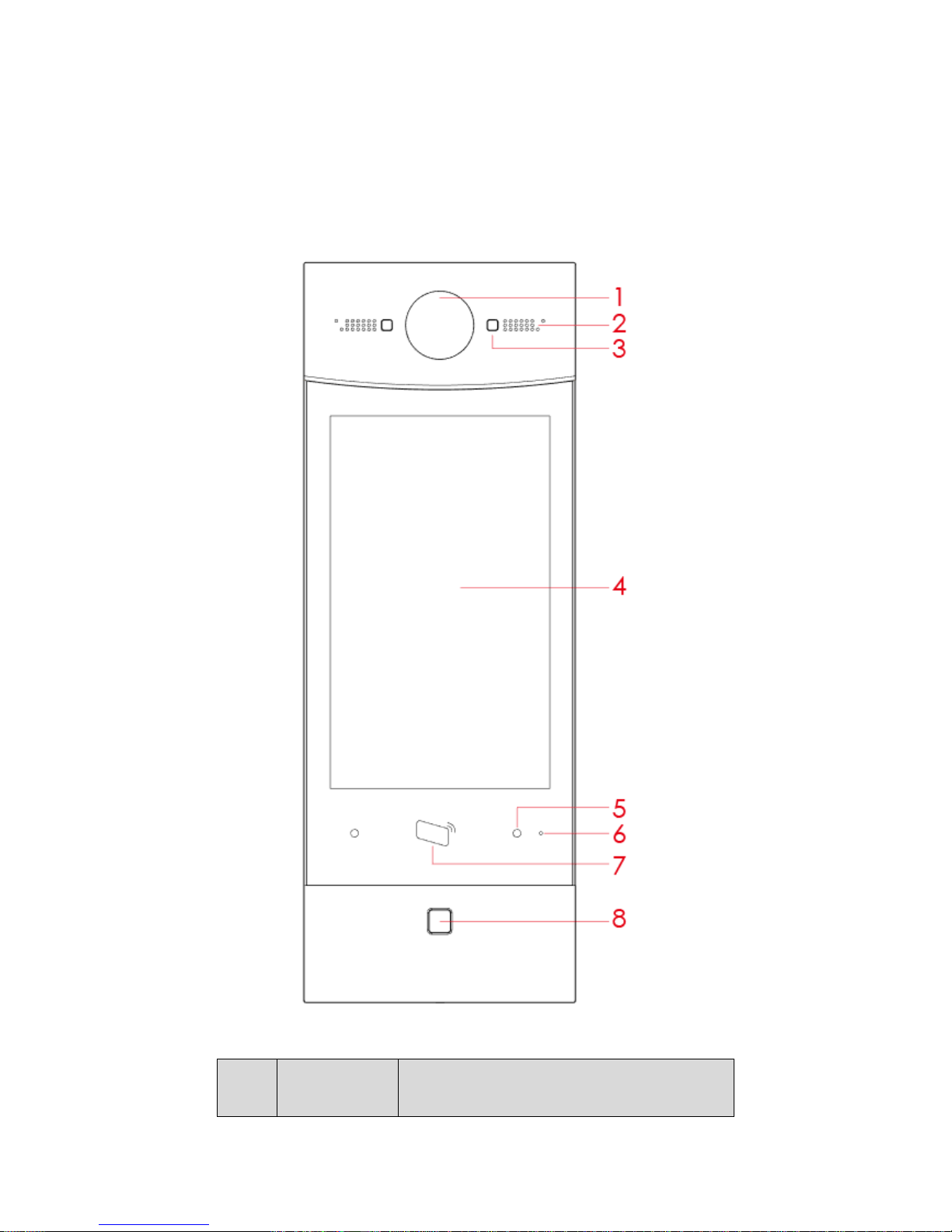
2.1 Front Panel
Figure 2-1 Front Panel
No. Component
Name
Description
Page 8

8
No. Component
Name
Description
1 Camera Monitor VTO video.
2 Speaker Sound output.
3 Backlight Backlight of camera.
4 Screen 10 inch IPS HD screen
5 Proximity
Sensor
When body or object approaches, the sensor
light is ON.
6 MIC Sound input.
7 Card Area
Authorize IC card unlock right (issue card),
card unlock
8 Fingerprint
Module
Recorded fingerprint can unl ock door.
Chart 2-1
Page 9
9
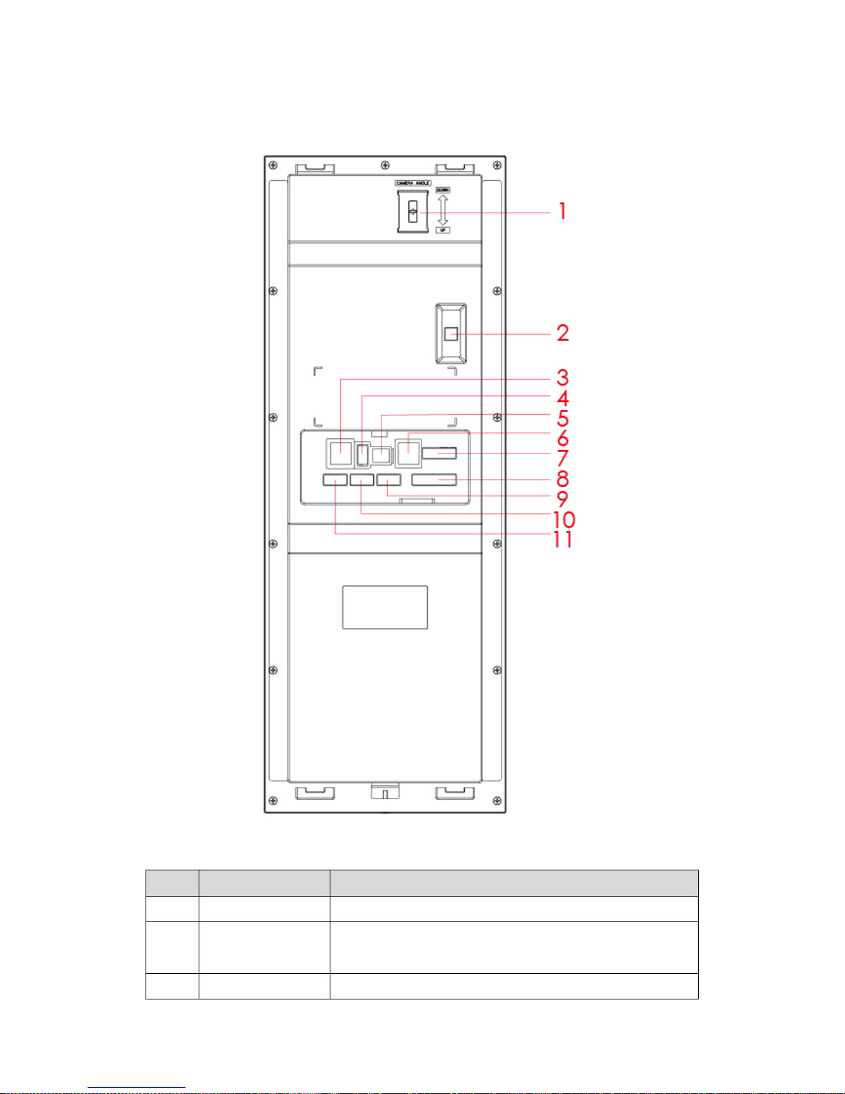
2.2 Rear Panel
Figure 2-2
No. Component Name Description
1 Camera Adjust Adjust camera.
2
Vandal-proof
When VTO is forced to leave wall, it will alarm and send
alarm to MGT center.
3 Network Standard RJ45 Ethernet cable.
Page 10

10
No. Component Name Description
4 USB Device debugging.
5 Power Input DC 12V power input
6 Analog Signal Analog signal connect to distributor
7 Lock Connect to unlock button and door sensor, control NO/NC
lock ON/OFF, see device rear lab el for details.
8 Wiegand Port Connect to wiegand device,
see device rear label for
details.
9 Alarm Out Include 2-ch alarm output and 2-ch alarm input, see device
rear label for details.
10 Alarm In
11 RS485 Connect to RS485 device, see device rear label for detai ls.
Chart 2-2
Page 11
11
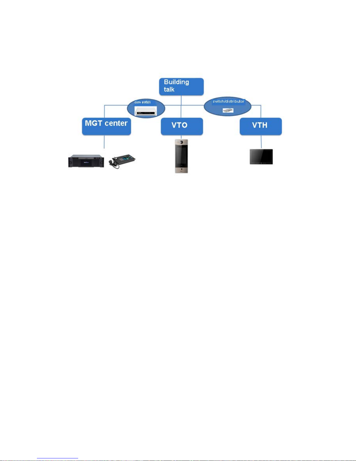
3 Networking
Figure 3-1
Page 12

12
4 Installation and Debug
4.1 Device Wiring
Please see device rear panel.
4.2 Installation
Warning:
Avoid installation in poor environment, such as condensation, high temperature, oil
stain, dust, corrosion or dir ect sunlight.
Project installation and debugging must be done by professionals. Please do not
open the device in case of failure, and please contact after sales service.
4.2.1 Screw
Component Name
Diagram
Quantity
M4×30 cross pan head
machine screw
2
Chart 4-1
Page 13
13
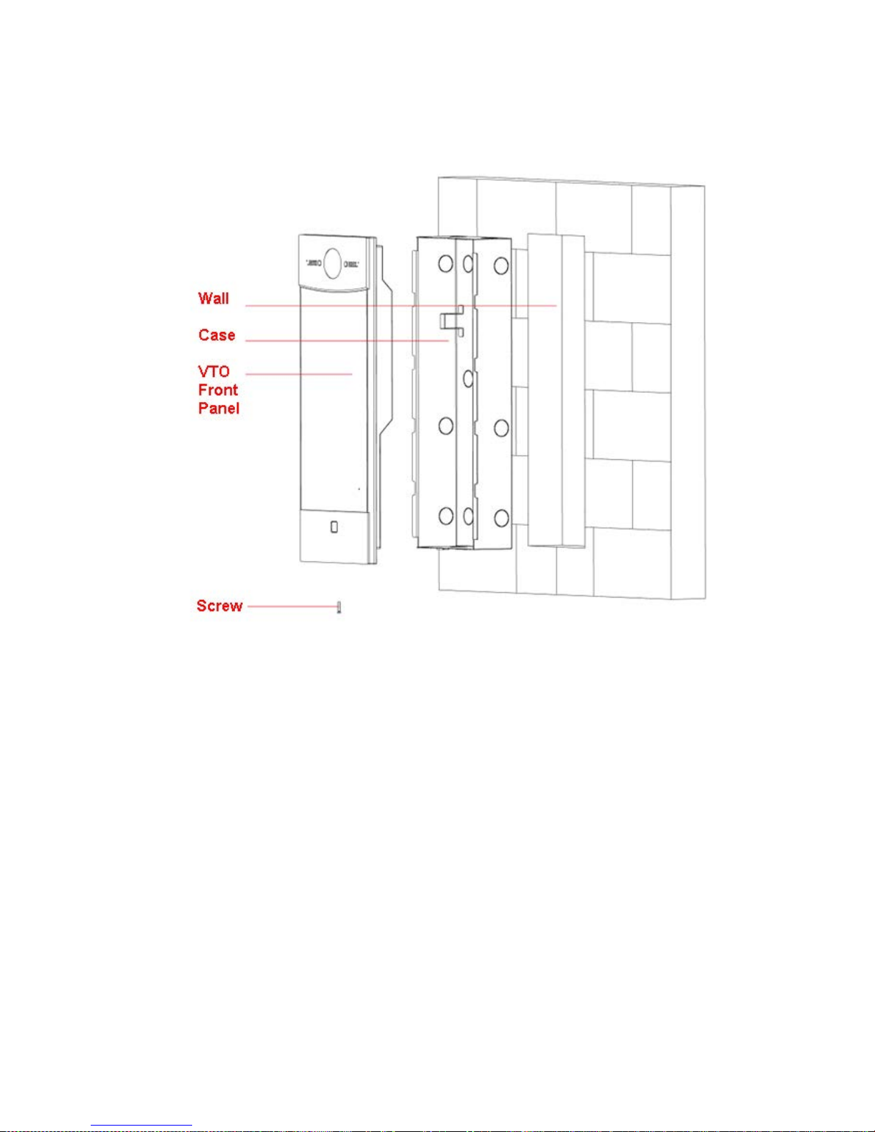
4.2.2 Installation Step
Figure 4-1
Step:
Step 1. On appropriate surface, e mb ed case into wall with cement.
Note:
During installation, the recommended distance from device center to ground is
1.4m~1.6m.
Step 2. Fix VTO front panel on the case with screws.
4.3 Device Debug
4.3.1 Before Debugging
Debugging personnel shall be familiar with related materials, know device installation,
wiring and usage.
Debugging personnel check whether circuit has short circuit or open circuit or not. Make
sure circuit is normal, plug device to power.
Page 14

14
After debugging end, clea r up sit e ( handle plugs, fix device and etc.)
VTO default IP address is 192.168.1.110. Before you use the VTO, please modify IP
address to be planned IP addr ess, so that VTO and VTH are in the same seg me nt .
Step to debug:
Step 1. Plug device to power.
Step 2. In PC Internet Explorer, enter default device IP address (192.168.1.119).
Step 3. Enter username and pass w or d.
Note:
Default username and passw or d ar e bot h admin. After first time login, please change
password ASAP, see Ch 5.2.6.3.
Step 4. Click Login.
Step 5. Modify device IP address to be planned IP address, see Ch 5.2.4.1. After
modification is done, WEB page restarts, go t o t he new IP address page.
4.3.2 Debug Device (VT System)
For example, connect to 10-inch VTH.
Step 1. Plug device to power.
Step 2. In homepage, long click Settings for 6 seconds. Device pops up Password
Verifi cat ion box.
Step 3. Enter project setup passwor d which is 888888 by default.
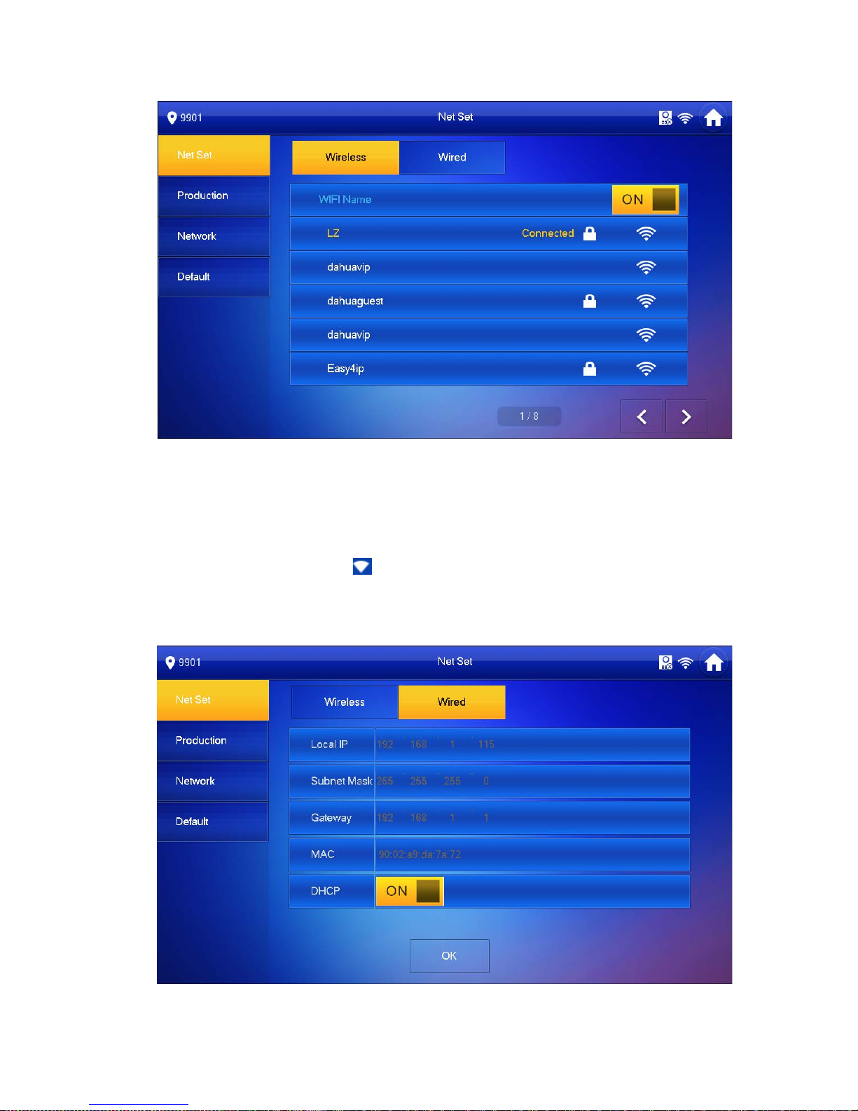
Step 4. Click Net Set to connect VTH.
Wireless:
If the VTH supports WI-FI, you can select wireless connection.
1. Select Wireless, open WLAN, view available WI-FI. See Figure 4-2.
Page 15
15
Figure 4-2
2. Select WI-FI you want to connect, and in pop-up WLAN connection
window, enter WI-FI password.
3. Click OK.
Now device interface shows at the upper-right corner which means wireless
connection is successful.
Wired:
1. Select Wired. See Figure 4-3.
Page 16
16
Figure 4-3
2. Enter VTH Local IP, Subnet Mask and Gateway.
3. Click OK.
Now device interface shows at the upper right corner which means wired connect ion
is successful.
Note:
You also can enable DHCP to auto gain VTH IP, subnet mask and gateway and click
OK to complete wired connection.
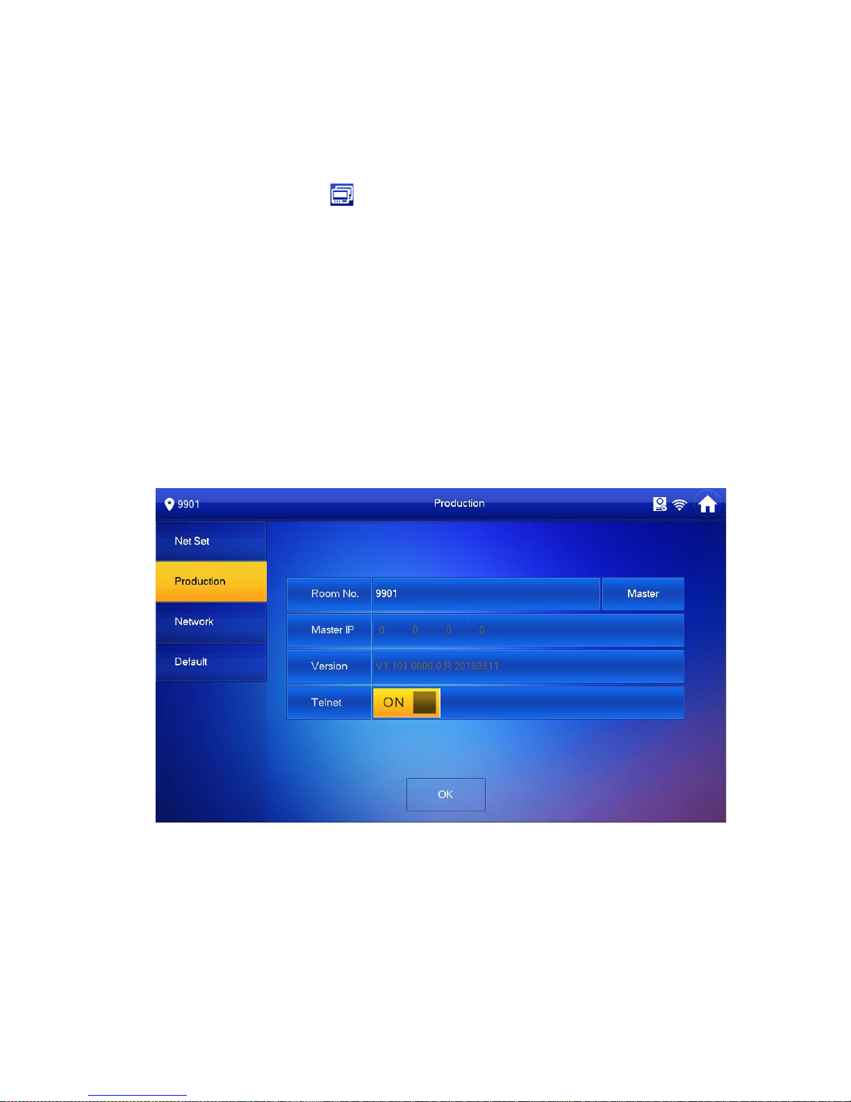
Step 5. Click Production to config VT H room no.
Warning:
VTH room no. must match VTH short no. on WEB of c or responding VTO.
If you want to set this VTH to be master VTH, then you shall select Master.
Fill in room no., click OK to save, see Figure 4-4.
Figure 4-4
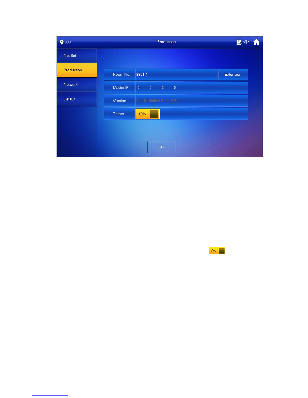
If you want to set this VTH to be ext ension VTH, then you shall select Extensi on.
1. Fill in user cinfig info for extension to auto sync with master, such as room
no. and master IP. See Figure 4-5.
Note:
Some extension config will auto sync with master VTH info, and cannot be
modified.
Page 17
17
Figure 4-5
2. Click OK to save config.
System pops up prompt inter face which means config is successful.
Note:
Telnet server is ON, debugging personnel can view VTH config via
telnet+IP.
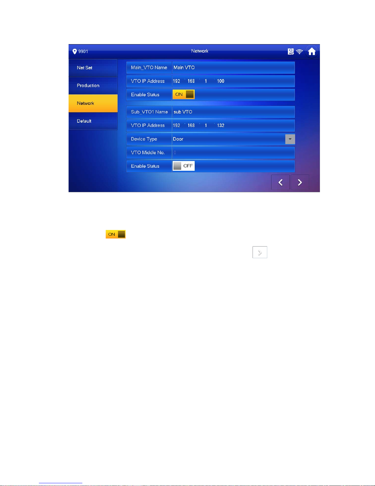
Step 6. Click Network to config VTO info.
Warning:
Before config, please make sure VTO is plugged to power and is in the same segment
with VTH.
1. Fill in VTO name, master VTO IP address, set enable status to , see Figure
4-6.
Page 18
18
Figure 4-6
2. Fill in VTO name, and extension VTO IP address, select device type, set enable
status to .
The device supports n19 units of extensions, and you can click to page down
to add more extensions.
4.3.3 Successfully Debug
On VTO dial VTO room no. to call VTH. VTH pops up monitoring video and operation
buttons, see Figure 4-7. You can accept call, hang up, snapshot, record, unlock and etc.
on VTH.
Page 19

19
Figure 4-7
Icon Icon Name Note
Unlock 1
VTO config electric control lock, click
, unlock.
Unlock 2
If this VTO has 485 expansion interface, it
can expand electric control lock or door
sensor lock, after successfully matching
with VTH, cl ick , unlock.
MIC
Click , turn off MIC volume.
IP Camera
Click ,
select IPC video of
monitoring favorites.
Snapshot
Click ,to snapshot.
Note:
When SD card is not installed, this button is
grey.
Record
Click , record ;
call ends, click
end recording.
Records are stored to SD card of this VTH,
Page 20

20
Icon Icon Name Note
if full, it overwrites from the earliest record.
Note:
When SD card is not installed, this button is
grey.
、
Volume Adjust call volume.
Accept Call -
Hang up -
Chart 4-2
Page 21

21
5 WEB Config
This chapter introduces WEB config of 10-inch touch screen VTO.
5.1 WEB Login and Logout
5.1.1 Login
Step 1. In Internet Explorer of PC enter planned IP address of VTO. See Figure 5-1.
Figure 5-1
Note:
Please confirm IP o f PC and IP of VTO are in the same segment.
VTO default IP addr ess is 192.168.1.110. See Ch 5.2.4.1. to change IP.
Step 2. Enter username and password.
Note:
Default username and password are both admin. Please change password ASAP
after first time login, see Ch 5.2.6.3.
Step 3. Enter Login.
5.1.2 Logout
Step 1. Select Logout>Logout>L ogout. See Figure 5-2.
Page 22

22
Figure 5-2
Step 2. Click Logout.
System exits WEB page. You can go to Logout>Reboot Device>Reboot Device, to
reboot the device.
5.2 System Config
5.2.1 Local Config
You can go to Local Config interface, set local, access control, talk, system time and
config.
5.2.1.1 Local Config
In page, select System Config>Local Config>Local Config. Set parameter, and click on
OK. See Figure 5-3.
Figure 5-3
Page 23

23
Parameter
Note
System Type Unit VTO scene includes digital system networking and analog
system networking. You can select corresponding system type.
Sensitivity of fill
light to open
During video talk, if environment is dark, auto enables light.
Range is 0~255, default is 60.
Storage Point Record, snapshot and other info can be st or ed i n FTP server or
SD card.
Note:
Please refer to Ch 5.2.4.2.
When you select SD card, please make sure you have
inserted SD card.
Shout Time Set VTH or MGT center call time with VTO.
Device Type Display device type. Now i t is unit VTO.
Reboot Date In set date, device will reboot. Default is 2 AM every Tuesday.
Main Ver sion Info
View software version.
MCU Version
Show MCU version, for troubleshooting.
Centre Control
Number
Default is 888888.
Default
Click Default to restore all par ameters in this page to default.
Refresh
Click Refresh to refresh this pag e.
OK
Click OK to confirm page content .
5.2.1.2 A&C Manager
Go to System Config>Local Config> A&C Manager, you can set unlock responding interv al,
unlock period and etc.
See Figure 5-4.
Page 24

24
Figure 5-4
Parameter Note
Unlock Responding
Interval
After being unlocked, interval before device responds to next
unlock. Unit is second.
Unlock Period After respond and unlock, time the door remained unlocked. Unit
is second.
Door Sensor Check
Time
Only when using door sensor lock, check “Check Door Sensor
Signal Before Lock”, valid only when “door sensor check time” is
set.
When door open time exceeds set door sensor check time, and
alarm occurs, you can view uploaded alarm in Info Search>Alarm
Info>Alarm Info.
Check Door Sensor
Signal Before Lock
Open Door
Command
Command from third party VDP.
Issue Card Password
Issue card password which may be changed.
Project Password Enter project setup interface with this password, it is 888888 by
default, may be changed.
Lift Control Protocol
Include local protocol and etc .
Protocol can set floor reach by user.
Check and enable lift control.
Lift Control Enable
New Unlock
Check “Common Password Enable” to enable a consistent
Page 25

25
Password password, so each user can unlock with this new password.
New Unlock
Password Confirm
Common Password
Enable”
New Menace
Password
Check “Menace Password Enable” to enable unlock function.
In emergency, if you enter menace password, the device will
report menace info to the MG T center.
New Menace
Password Confirm
Menace Password
Enable
Auto Snapshot
Once enabled, it will auto snapshot if you unlock via card,
password. It also uploads snapshot to FTP.
Default Restor e all device parameters in the tab to default setting.
Refresh Click Refresh to refresh the page.
5.2.1.3 Talk Manager
In System Config>Local Config>Talk Manager interface, you can set auto snapshot,
publish overlay and etc. See Figure 5-5.
Figure 5-5
Parameter Note
Auto Snapshot
Select “Turn on”, so when a user calls, it will snapshot once and upload to
FTP.
Publish Overlaying
Select “Turn on”, publish info auto overlays to System Config >Video Set >
Video Set preview, and roll.
Remove Analog
Publish
Click “Remove Publish In fo” , delete all i nfo in Sy st em Config> Pub lish In fo >
History.
Default Click “ De fault”, to restore all parameters in this page to default.
Refresh Click “Refresh”, to refresh t his page.
Page 26

26
5.2.1.4 System Time
In page, select System Co nf ig>Local Config>System Time.
Set date format, time format, system time, NTP server address, time zone and port. See
Figure 5-6.
Figure 5-6
Parameter
Note
Date Format
Set date format of display.
Time Format
Set time format of display as 12-hour and 24-hour.
System Time
Set system display time.
Sync PC Click “Sync PC”, to sync system time with PC time.
NTP Conf ig
Check “NTP Config”, to enable NTP server net sync time.
You also can enter IP, zone, port and upgrade period of PC where NTP
server is installed to set n et t ime sy nc.
NTP Server
Zone
Port
Upgrade Period
Default
Click “Default”, to restore all p ar ameters in this page to default.
Refresh
Click “Refresh”, to refresh t his page.
5.2.1.5 Config Manager
In page, select System Config>Local Config>Config Manager. Here you can set export
config, import config and default. See Figure 5-7.
Page 27

27
Figure 5-7
Paraemter Note
Export Config
Import or export system config file, when more than one device need to set
the same parameter, a user can backup config file.
Export config file(Config.backup).
Import config file.
Import Config
Default All
Device all parameters will be r est or ed t o default.
5.2.2 LAN Config
In page, select System Config>LAN Config, you can set VTO No., support group call and
server type. See Figure 5-8.
After you have set config, go to Logout>Reboot>Reboot, click Reboot Device to make
config effective.
Figure 5-8
Parameter
Note
No.
Unit VTO no.
Note:
If the device is SIP server, a user can edit this no. SIP server
setup refers to Ch 5.2.4.3.
Support Group
Select T urn on, to enable group call.
Page 28

28
Parameter Note
Server T ype
Select server type of device. If this device is SIP server, select
VTO for server type.
Default
Click “Default”, to restore all p ar ameters in this page to default.
Refresh Click “Refresh”, to refresh t his page.
5.2.3 Device Manager
Note:
Visible if this dev i ce i s used as SIP server.
Support to add, modify and delete VT O and VTH. One VT O suppor ts more th an one V TH.
5.2.3.1 Outdoor Station Mana ge r
Note:
If the device is used as SIP ser ver, then added VTO will be a sub VTO of this VTO.
Step 1. Select System Config>Device Manager>Outdoor Station Manager.
System shows Outdoor Stat ion Manager interface.
Step 2. Click Add. System shows Add interface.
Step 3. Fill in VTO no., format is “80XX” and VTO IP address ( opt ional).
See Figure 5-9.
Figure 5-9
Step 4. Click OK, to complete.
See Figure 5-10.
Page 29

29
Figure 5-10
Click to modify VTO parameter info. Click to delete added VTO.
Note:
For VTO in use, you cannot modify it or delete it.
5.2.3.2 Indoor Station Mana ger
Warning:
After you have added a single VTH, we do not recommend you to batch add VTH,
since this operation will overwrite original VTH. Please add VTH one by one after
batch operatio n.
You can add VTH via either method below:
Add one VTH
Step 1. Select System Config>Device Manager>Outdoor Station Manager. System
shows Outdoor Station M anager interface.
Step 2. Check VTO you want to add VTH, such as 8001.
Step 3. Select “8001-indoor station manager” tab.
Step 4. Click Add. System shows Figure 5-11.
Figure 5-11
Step 5. Configure parameters, see chart below.
Page 30

30
Parameter Note
Family
Name
Set VTH username.
First Name
VTH Short
No.
As VTH room no.
Note:
VTH short no. is composed of 1-5 digits of number.
If your VTH room no. need group call function, please make sure you
have enabled group call in Sys tem Con fig>L AN C onf ig>L AN Con fig, a nd
add “-0” behind VTH short no., add “-1”, “-2
” and so forth behind
extension short no. Otherwise, VTH will only calls main VTH when dial
the room no.
Register
Password
SIP system signal com m and interacting, use default is OK.
Register
Type
Step 6. Click OK, to complete VTH, see Figure 5-12.
Figure 5-12
Batch add VTH
Batch add multiple VTHs, up to 1024.For example, add 5 floors and each floor has 4 VTH.
Step 1. Select System Config>LAN Config>Residence Config. System shows Residence
Config interface.
Step 2. Configure parameter, see Figure 5-13.
Page 31

31
Figure 5-13
Step 3. Check Create Room No., to enable batch add VTH.
Step 4. Click OK.
See Figure 5-14.
Figure 5-14
Page 32

32
Step 5. Click to modify VTH username, password, registration and its password.
Click to delete VTH.
Tips:
If your VTH room no. n eed group call function, please ma ke sure you have enabled group
call in System Config>LAN Config>LAN Config, and add “-0” behind VTH short no., add
“-1”, “-2” and so forth behind extension short no. Please refer to Ch 5.2.3.2.
5.2.3.3 Card Manager
Warning:
Please add VTH first and the n issue card. Please refer to Ch 6.1.3..
In Figure 5-14, c lick , to view all issued cards under this VTH, see Figure 5-15 and
chart below.
Figure 5-15
Parameter Note
Card ID
Show IC card’s card ID, user name and VTH room. No.
Card
Number
Username
Main Card
Check “main card”, set this I C card as main card.
Note:
Main card can issue card.
Report
Loss
When IC card is lost, click to report loss. After reporting loss, t he IC card
cannot unlock door.
Modify
Click , to modify this IC card username.
Delete
Click , to delete this IC card.
Page 33

33
5.2.3.4 Config Manager
You can import or export syst em con f ig file, when more than one device need t o s et same
parameter, you can use backup config file.
Step 1. Select System Config>D evice Manager>Config Manager.
See Figure 5-16.
Figure 5-16
Step 2. Config import/export.
Config export.
1. Click “Export Config”. Sys t em s how s E x por t box, see Figure 5-17.
Figure 5-17
2. Select export type you need to export (device info/card info/password in fo).
3. Click OK.
4. Click Save.
System prompts “operatio n is successful.”, export is complete.
Config import
1. Click “Import Config”. Sy st em s hows Import box.
2. Select config file (.log)you need to import, click O pen.
System prompts “operatio n is successful.”, import is complete.
5.2.4 Network Config
5.2.4.1 TCP/IP
Go to System Config>Network Config>TCP/IP interface, you can set VTO IP address,
subnet back, default gateway, see Figure 5-18.
Please refer to chart below. After config is complete, W EB interface and VTO will both
Page 34

34
reboot. After a while, WEB interface directly goes t o new IP address.
You also can modify VTO IP in Project Setup>IP Setup local interface.
Figure 5-18
Parameter
Note
IP Address
Enter number as IP address.
Subnet Mask
According to actual con dition, subnet mask prefix is number, enter
1~255,part of subnet prefix is a special network link, which in
general include a layer structure.
Default Gateway
According to actual condition, it must be in the same segment
with IP address.
MAC Address
Show device MAC address.
Default Click “Default”, to restore all parameters in this pag e t o default.
Refresh Click “Refresh”, to refresh t his page.
5.2.4.2 FTP Config
Back up record and picture t o set FTP server for storage and view.
Note:
FTP is enabled by default.
Step 1. Select System Config>Network Config>FTP Config. See Figure 5-19.
Page 35

35
Figure 5-19
Step 2. Configure interface param et er, see chart below.
Parameter
Note
IP Address Host IP address where FT P is inst alled.
Port No. Default is 21.
Username
Username and password t o ac cess FTP server.
Password
Step 3. Click OK, to complete FTP setup.
5.2.4.3 SIP Server
When unit VTO is as SIP serv er, one SIP server can manage 200 un its of device. Set
the device to be SIP server, operation as follows:
Step 1. Select System Config>N etwork Config>SIP Server. See Figure 5-20.
Figure 5-20
Step 2. Check “SIP Server Enable”, to enable the device as SIP server.
After complete, unit VT O will reboot.
When unit V TO is not as SIP server, you can select other SIP server, and setup as
follows:
Step 1. Select System Config>N etwork Config>SIP Server Config.
System shows SIP Ser ver Config interface.
Parameter
Note
IP Address
SIP server IP address.
Port
When SIP server IP is filled as VTO IP address, default network
port is 5060;when SIP server IP is filled as H500 platform IP
address, default network port is 5080.
Page 36

36
Parameter Note
Username
SIP server login usernam e and password.
Default username is VTO no., and default password is 888888.
Password
SIP Domain SIP server domain, can be null.
Step 2. Enter parameter.
Step 3. Click OK.
5.2.4.4 Port Config
Step 1. Select System Config>Network Config>Port Config. See Figure 5-21.
Figure 5-21
Step 2. Configure parameter, see chart below.
Parameter
Note
WEB Port
Set port to login unit VTO WEB interface, default is 80;you also
can go to VTO host “project setting > WEB port” to view WEB
port no.
If the port is occupied, you can use 1025~65535 range, in
browser enter “http://VTO IP:WEB port no.”to visit VTO WEB
interface.
SIP Port SIP server port, defau lt is 5060.
RTP Port Video pull stream port, default is 15000.
SIP Router Add Check “Enable” to enable router function.
Click “router setup”, in pop-
up box enter H700 platform IP
address, port no. is 5080.
Setting
Step 3. Click OK.
Page 37

37
5.2.4.5 DDNS Config
DDNS(Dynamic Domain Nam e Server), is dynamic upgrade of domain name and IP
address of DNS server when device IP address is changing frequently. This can
guarantee user access to device via domain name.
Warning:
Before config, please make sure the device support DNS type, and login
corresponding DDNS username, password and etc.
User register on DDNE website and login, thus can view all connected device info
under this user.
Step 1. Select System Config>Network Config>DDNS. See Figure 5-22.
Figure 5-22
Step 2. Check Enable to enable DDNS s er ver function.
Step 3. Config parameter, refer to chart below.
Parameter Note
Server T ype
DDNS server
provider name and address, corresponding relation as
follows.
Dyndns DDNS address:members.dyndns.org
NO-IP DDNS address is:dynupgrade.no-ip.com
As select “server type” to be NO-
IP DDNS, server name is
dynupgrade.no-ip.com.
Server Name
Server Port DDNS server por t .
Domain User registered domain o n DDNS server provider website.
User
Enter username and password received from DDNS server provider.
User shall register on DDNS server provider website (username and
password included).
Password
Page 38

38
Parameter Note
DDNS Live
Time
DDNS server live time.
Step 4. Click OK, to complete DDNS ser ver setup.
In PC web browser enter domain name, and press Enter. If it shows device WEB page,
the operation is successful. I f not, config failed.
5.2.5 Video Set
5.2.5.1 Video Set
In page, select System Co nf ig> Video Set>Video Set.
You can set camera brightness, contrast, HUS and etc. See Figure 5-23.
Figure 5-23
Note:
If you cannot see v ideo, please install plug in f irst.
Parameter
Note
Main Format
Video Format
Adjust video resolution, as 720P, WVGA and D1.
720P: resolution is 1280*720.
WVGA:resolution is 800×480.
D1:resolution is 720× 576.
Frame Rate
Adjust video transmission speed, as 30 and 25 fps.
Extra Format Video Format
Adjust video resolution, as WVGA and D1, QVGA:
WVGA:resolution is 800×480.
Page 39

39
Parameter Note
D1:resolution is 720×576.
QVGA::resolution is 320×240.
Frame Rate
Adjust video transmission speed, as 30 and 25 fps.
Bit Rate
According to actual device input network, select bit rate,
as 256Kbps,512Kbps,1Mbps,2Mbps and 3Mbps.
Brightness
Adjust video brightness
Contrast
Adjust video contrast
HUE
Adjust video HUE
Saturation Adjust video saturation
Gain Mode Auto mode: system automatically adjusts.
Scene Mode Includes: disabled, automatic, sunny and night.
Day/Night Mode Includes: colorful, automatic, black white.
Back Light Mode
Four modes available:
Mirror Horizontally flip video.
Flip
Vertically flip video.
Default
Restore all parameter in vi deo set t ab to default.
5.2.5.2 Audio Set
Go to System Config>Video Set>Audio Set interface, you can set MIC volume and beep
volume. See Figure 5-24.
Figure 5-24
Click Default to restore all par ameters in Audio Set inter fac e to default.
5.2.6 User Manage
5.2.6.1 Add User
Step 1. In page, select System Co nf ig>User Manager.
Step 2. Click on Add User.
Step 3. In pop-up box fill in user info. Se e Figure 5-25.
Page 40

40
Figure 5-25
Note:
Currently the system supports two user types: admin and user.
Admin has higher rights with fu ll oper ation rights.
User can only view sy stem c on figurati on, u nloc k, e xport record, send pu blish info a nd
modify user password.
Step 4. Click OK, complete WEB i nt er fac e adding of user, see Figure 5-26.
Figure 5-26
5.2.6.2 Delete User
In User Manage interface, c lick on to delete user.
5.2.6.3 Modify User
Step 1. Select user you want to modify, click .
Step 2. Check “Change Password” , see Figure 5-27.
Page 41

41
Figure 5-27
Step 3. Enter old password, new passwor d and confirm new password.
Step 4. Click OK.
5.2.7 IPC Information
Note:
Visible when this dev ice is as SIP server.
You can add up to 20 IPCs, and added camer as w ill be auto synced with VTH.
To add IPC:
Step 1. Select System Config>IPC Information>IPC Information.
Step 2. Click , sy st em pop s up a bo. See Figure 5-28.
Figure 5-28
Step 3. Fill in IPC information, see char t below.
Parameter
Note
IPC Name
IPC name.
IP
IPC IP.
Page 42

42
Parameter Note
Address
Username
Login IPC WEB interface user name and password.
Password
Step 4. Click OK.
5.2.8 Publish Information
In Publish Information page, you can send publish information and view historical
information.
Note:
Visible when the device is as SIP server.
5.2.8.1 Send Info
In page, select System Config>Publish Information>Send Info. You can set validity
published info, select device to send info or check “all devices” and etc. Click Send, see
Figure 5-29.
Figure 5-29
5.2.8.2 History Info
In page, select System Co nf ig>Publish Information>History Info.
You can view historical information, click on to delete ifnormation. See Figure 5-30.
Page 43

43
You also can go to System Config>Local Con fig>Talk Manager interface, to delete publis h
info.
Figure 5-30
5.2.9 UPnP Setup
Note:
Visible when the device is set as SIP server.
Warning:
Login router, set router WAN port IP address connection to WAN.
Router enables UPnP function.
Connect device to router LAN port, to private network.
Via UPnP protocol create mapping relationship between private network and outer
network. Outer network user can visit device in LAN via outer IP address.
Step 1. Select System Config>UPnP Setup>General.
Step 2. Check “UPnP Enable” t o enable UPnP function.
Step 3. Click Add. See Figure 5-31.
Figure 5-31
Step 4. Enable UPnP function, select enable, see chart below.
Parameter Note
Server
Name
Server name.
Protocol
Type
Select protocol type, TCP or UDP.
Page 44

44
Parameter Note
Inport Port to mapping.
Outport Port mapped on router.
Note:
When you set router mapping outer port, try use port within 1024~5000, to avoid
using well-known port 1~2 55 and system port 256~1023.
When there are multiple devices in the same LAN, please plan for port mapping, to
eliminate multiple device mapping to one external port.
For port mapping in progress, please make sure mapping port is not occupied or
limited.
TCP/UDP internal and exter nal ports must be identical, cannot be modified.
Step 5. Click OK, to complete UPnP setup.
In browser, enter “http://WAN IP
:
WAN port no.”to visit corresponding router port no.
of private device.
5.2.10 Fingerprint Info
You can record up to 3000 fingerprints.
Go to System Config>Fingerprint Manager>Fingerprint Info, you can delete, add, import
and export fingerprint info.
5.2.10.1 Add Fingerprint
After you add fingerprint, y ou can unlock via fingerprint.
Add single fingerprint
Step 1. Select System Config>Fingerprint Manager>Fingerprint Info.
Step 2. Click Register, see Figure 5-32.
Figure 5-32
Note:
Room no. in fingerprint manager shall be identical with room no. set in System
Config>Device Manager> I ndoor Station Manager.
Page 45

45
Step 3. Enter username and room no. of the f ingerprint, click OK.
Step 4. Follow audio instructions to enter fingerprint for three times on VTO. If
verification fails, please ent er fin ger print again. See Figure 5-33.
Figure 5-33
Batch add fingerprint
Step 1. Select System Config>Fingerprint Manager>Fingerprint Info.
Step 2. Click Fingerprint Import.
Step 3. Select fingerprint info (.csv) file, click Open. System will prompt when operat ion
is successful.
5.2.10.2 Delete Fingerprint
Go to System Config>Fingerprint Manager>Fingerp rint Info inter face, y ou can click to
delete added fingerprint in fo. You can click Remove All to delete all added fingerprints.
5.2.10.3 Modify Fingerpri nt
Go to System Config>Fingerprint Manager>Fingerprint Info interface, you can click
to modify fingerprint info.
5.2.10.4 Export Fingerprint Info
Step 1. Select System Config>Fingerprint Manager>Fingerprint Info.
Step 2. Click Fingerprint Export to Temp, to export into Browser cache.
Step 3. Click OK. ‘
Step 4. Click Export to Excel From Temp.
Step 5. Select path, save fingerpri nt info.
Page 46

46
5.3 Info Search
You can view call record, alarm record an d unlock record.
5.3.1 Call Record
Store up to 1024 records.
Select Info Search>Call History>Call History. You can search VTO call records, including
call type, room no., start time, ca ll time and end status. See Figure 5-34.
Figure 5-34
Click Export Record to expor t call record of VTO.
5.3.2 Alarm Record
Store up to 1024 records, includ ing door sensor alarm, vandal-proof alarm an d etc.
Select Info Search>Alarm Record>Alarm Record interface, you can search unit VTO
alarm, including room no., alarm status and etc, see Figure 5-35.
Figure 5-35
Click Export to export VTO alarm record.
Page 47

47
5.3.3 Unlock Record
Unlock record stores up to 1000 records, including remote unlock, card unlock and but t on
unlock.
In Info Search>Unlock Record>VTO Unlock Record interface, you can search unit VTO
unlock status, including unloc k type, unlock time and etc. See Figure 5-36.
Figure 5-36
Click Export Record to expor t VTO unlock record.
5.4 Status Statistics
In Status Statistics>VTH Status>VTH Status interface, you can view VTH connection
status, IP port and etc. See Figure 5-37.
Figure 5-37
Step 1. Status
Offline: VTO and VTH are not connected, you cannot call, mon it or, talk or etc.
Online: VTO and VTH ar e connected, you can call, monitor, talk and etc.
Page 48

48
6 Functional Operation
VTO supports unlock via fingerprint, password, card, QR code, and to call MGT center
and VTH. It also supports video intercom with MGT center and VTH.
6.1 Project Setting
In Project Setting interface, for engineer config only. Password to enter is 888888.
Note:
Project setting password can be changed on WEB, see Ch 5.2.1.2.
6.1.1 IP Config
In Project Setting>IP Config interface, you can set VTO IP address, subnet mask and
gateway, see Figure 6-1.
Figure 6-1
Page 49

49
6.1.2 Volume Config
In Project Setting>V o lume Config interface, you can control volu me of entire VTH, inclu ing
touch screen tone, VTH ring, alarm tone and etc. There are recommended values, see
Figure 6-2.
Figure 6-2
6.1.3 Issue Card
Step 1. Select Project Setting>Iss ue Card, see Figure 6-3.
Page 50

50
Figure 6-3
Step 2. Select method to issue car d.
Master card.
1. Select master card.
Note:
Set authorized card to be mast er car d, r ef er r ing to Ch 5.2.3.3.
2. At device card area, swipe mast er car d.
Note:
Room no. entered shall be identical with room no. set in VTO WEB System
Config>Device Manager> I ndoor Station Manager.
3. Enter room no., press OK.
4. Swipe card at card area. Please swipe card to be authorized.
After authorization is successful, it will prompt, and you can go to System
Config>Device Manager> I ndoor Station Manager, clic k to view.
Password
1. Select Password.
2. Enter card issuing password, click OK.
Note:
Page 51

51
Room no. entered shall be identical with room no. set in VTO WEB System
Config>Device Manager> I ndoor Station Manager.
3. Enter room no., press OK.
5. Swipe card at card area. Please swipe card to be authorized.
After authorization is successful, it will prompt, and you can go to System
Config>Device Manager> I ndoor Station Manager, clic k to view.
6.1.4 Info
In Project Setting>Device Info interface, you can view WEB port and MCU version, see
Figure 6-4.
Figure 6-4
Page 52

52
6.2 Unlock
6.2.1 Unlock via Fingerprint
At fingerprint area of VT O , enter recorded fingerprint to unlock.
See Ch 5.2.10.1.
6.2.2 Unlock via Password
On VTO enter “#+unloc k password+, to unlock.
See Ch 5.2.1.2.
6.2.3 Unlock via Card
Note:
Visible only when VTO is set as SIP server.
At card area on VTO, swi pe authorized card to unlock.
See Ch 6.1.3.
6.2.4 Unlock via QR Code
QR code issued by the platform, and can be scanned by camera on VTO to unlock, see
Figure 6-5.
Page 53

53
Figure 6-5
6.2.5 Unlock via VTH
When VTH is being called, mon itor ed or on a call, it all can remotely unlock VTO.
After it hangs up or countdown end s , it can r eturn to standby interface.
6.3 Call Function
6.3.1 Call MGT Center
Press on VTO screen to call MGT center, see Figure 6-6.
Page 54

54
Figure 6-6
Note:
MGT center no. can be modified on VTO WEB, see Ch 5.2.1.1. Defau lt is 888888.
6.3.2 Call VTH
On VTO enter “room no.+call ” to call corresponding VTH, see Figure 6-7.
Page 55

55
Figure 6-7
6.4 Default
See Ch 5.2.1.5.
Page 56

56
Appendix 1 Technical Specifications
Model
DH-VTO9221D
DH-VTO9231D
System
Main Process
Embedded micro
controller Embedded micro contro lle r HI3521
OS Embedded Linux os Embedded Li nux os
Video
Video Compression
Standard
H.264
H.264
Input 2.0 MP HD camera 2.0 MP HD camera
Night Vision Support Support
BLC
Support
Support
Auto Fill Light Support Support
Audio
Input
Omnidirectional Mic
Omnidirectional Mic
Output Built-in speaker Built-in speaker
Talk
Support bidirectional talk
Support bidirectional talk
Display
Screen Dimension
10 inch TFT screen
10 inch TFT screen
Resolution 1280×800 1280×800
Operation Mode
Input
Capacitive touch screen
Capacitive touch screen
Card Built-in IC card sensor Built-in IC card se nsor
Fingerprint
Not support
3000 fingerprints
Proximity
Body Proximity Support Support
Alarm
Vandal-proof Support Support
Access Control
NO Output Support Support
NC Output Support Support
Unlock Button
Support
Support
Door Status Check Support Support
Network
Support 10M/100Mbps
self-adaptive 10M/100Mbps self-adaptive
Support
TCP/IP
TCP/IP
General
Power
DC 10V-15V
DC 10V-15V
Consumption Standby≤8W; tandby≤8W; working≤18W
Page 57

57
Model
DH-VTO9221D
DH-VTO9231D
working≤18W
Working Environment
-40℃~+60℃
-40℃~+60℃
10%RH~95%RH 10%RH~95%RH
Protection IP54 IP54
Dimensions
475mm×174mm×58mm
475mm×174mm×58mm
Note:
This manual is for reference only. Slight difference may be found in user
interface.
All the designs and software here are subject to change without prior written
notice.
All trademarks and registered trademarks are the properties of their respective
owners.
If there is any uncertai nty or controv ersy, please refer to the final explanation of
us.
Please visit our website or contact your local service engineer for more
information.
 Loading...