

Page 1

i
Multi-spectral Thermal Camera Web3.0
Operation Manual
Version 1.0.0
Page 2

ii
Table of Contents
1 Network Config ............................................................................................................................ 1
1.1 Network Connection ..................................................................................................... 1
1.2 WEB Interface Login ..................................................................................................... 1
2 Live ................................................................................................................................................ 4
2.1 Video Window Function Option .................................................................................. 5
2.2 Video window Adjustment ........................................................................................... 7
2.3 More Functions .............................................................................................................. 9
2.3.1 Local Record and Capture ........................................................................................ 9
2.3.2 Realtime Spot Temperature Measurement ............................................................. 10
2.3.3 Laser Ranging ......................................................................................................... 11
3 PTZ .............................................................................................................................................. 13
3.1 Bullet Camera .............................................................................................................. 13
3.1.1 Setting Protocol ...................................................................................................... 13
3.1.2 Setting Function ...................................................................................................... 14
3.1.3 PTZ Control ............................................................................................................ 17
3.2 Speed Dome and PTZ ............................................................................................... 19
3.2.1 Setting Protocol ...................................................................................................... 19
3.2.2 Setting Function ...................................................................................................... 20
3.2.3 PTZ Control ............................................................................................................ 31
4 Playback ..................................................................................................................................... 34
4.1 Video Playback ............................................................................................................ 34
4.1.1 Play Control Bar ..................................................................................................... 36
4.1.2 Playback Video ....................................................................................................... 36
4.1.3 Video Clip ............................................................................................................... 42
4.1.4 Assistant Function .................................................................................................. 43
4.2 Picture Playback ......................................................................................................... 43
5 Report ......................................................................................................................................... 48
6 Setup ........................................................................................................................................... 50
6.1 Camera ......................................................................................................................... 50
6.1.1 Conditions ............................................................................................................... 50
6.1.2 Video ...................................................................................................................... 65
6.1.3 Audio ...................................................................................................................... 78
6.2 Network ......................................................................................................................... 79
6.2.1 TCP/IP .................................................................................................................... 79
6.2.2 Connection .............................................................................................................. 82
6.2.3 PPPoE ..................................................................................................................... 84
Page 3

iii
6.2.4 DDNS ..................................................................................................................... 85
6.2.5 IP filter .................................................................................................................... 88
6.2.6 SMTP (E-mail) ..................................................................................................... 89
6.2.7 UPnP ....................................................................................................................... 91
6.2.8 SNMP ..................................................................................................................... 92
6.2.9 Bonjour ................................................................................................................... 96
6.2.10 Multicast ................................................................................................................. 96
6.2.11 802.1x ..................................................................................................................... 98
6.2.12 QoS ......................................................................................................................... 99
6.3 Peripheral ................................................................................................................... 100
6.3.1 IR Light ................................................................................................................. 100
6.3.2 Wiper .................................................................................................................... 101
6.3.3 Fan ........................................................................................................................ 102
6.3.4 Heater .................................................................................................................... 103
6.4 Smart Thermal ........................................................................................................... 103
6.4.1 IVS Analyse .......................................................................................................... 104
6.4.2 Face Detection ...................................................................................................... 115
6.4.3 Fire Warning ......................................................................................................... 116
6.4.4 Cold Hot Spot Follow ........................................................................................... 119
6.4.5 Pic in Pic ............................................................................................................... 121
6.4.6 Link Schedule ....................................................................................................... 122
6.5 Event ........................................................................................................................... 123
6.5.1 Video Detect ......................................................................................................... 123
6.5.2 Temperature Alarm ............................................................................................... 129
6.5.3 Alarm Setting ........................................................................................................ 130
6.5.4 Abnormity ............................................................................................................. 131
6.6 Temperature .............................................................................................................. 134
6.6.1 Rule ....................................................................................................................... 134
6.6.2 Global ................................................................................................................... 138
6.6.3 Heatmap ................................................................................................................ 142
6.7 Storage Management ............................................................................................... 143
6.7.1 Schedule ................................................................................................................ 143
6.7.2 Destination ............................................................................................................ 149
6.7.3 Record control ...................................................................................................... 152
6.8 System ........................................................................................................................ 153
6.8.1 General .................................................................................................................. 153
6.8.2 Account ................................................................................................................. 155
6.8.3 Default .................................................................................................................. 159
6.8.4 Import & Export ................................................................................................... 159
Page 4

iv
6.8.5 Auto Maintenance ................................................................................................. 160
6.8.6 Upgrade ................................................................................................................ 161
6.9 Information ................................................................................................................. 161
6.9.1 Version .................................................................................................................. 161
6.9.2 Log ........................................................................................................................ 162
6.9.3 Online User ........................................................................................................... 163
7 Alarm ......................................................................................................................................... 165
8 Log out ...................................................................................................................................... 167
Page 5

v
Important
The following functions are for reference only. Some series products may not
support all the functions listed below.
Page 6
1
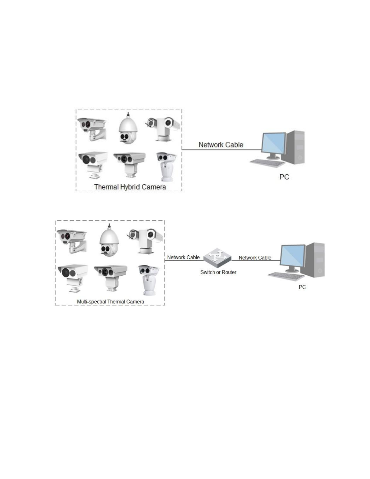
1 Network Config
1.1 Network Connection
There are mainly two connection modes between camera and computer, please refer to Figure 1-1 and
Figure 1-2.
Figure 1-1
Figure 1-2
Before you get access to network camera via the Internet, first you need to acquire its IP address. User
can use quick config tool to search IP of the network camera. Please refer to Quick Configuration Tool
manual for more details.
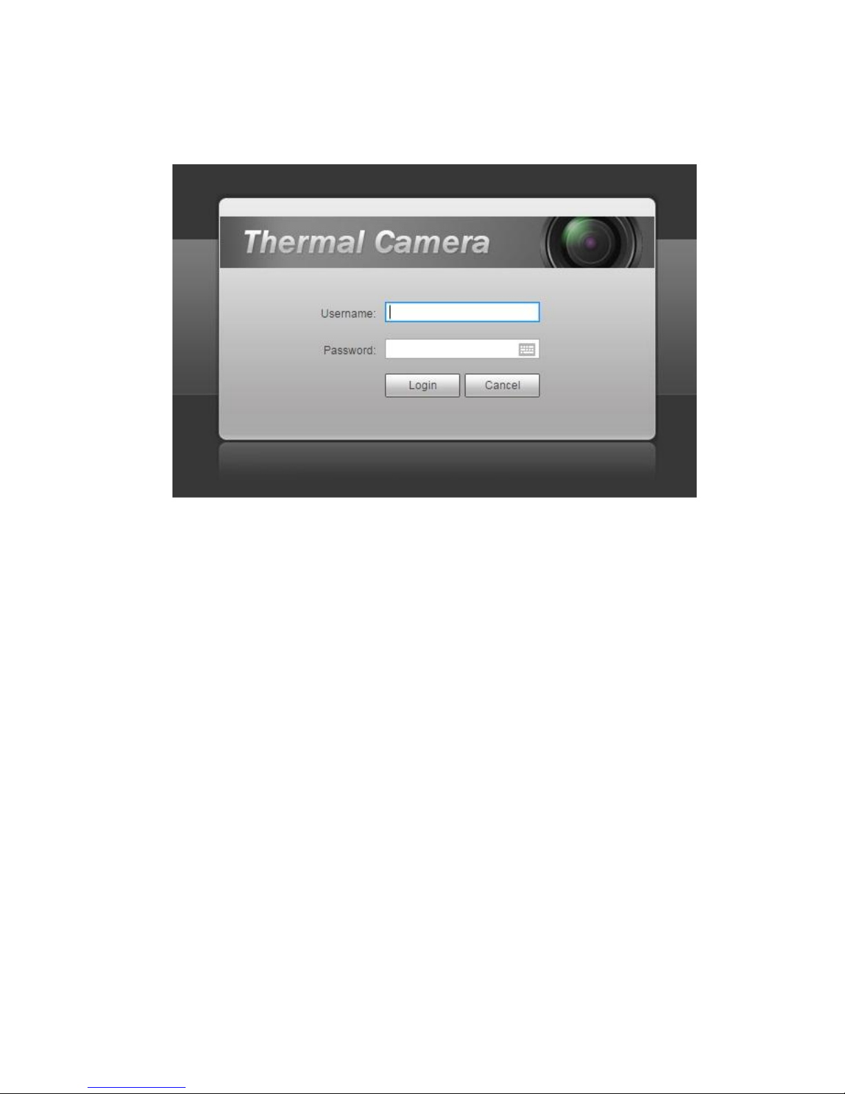
1.2 WEB Interface Login
Step 1
Open IE and input the IP address of the camera in the address bar.
The system will display the “Login” interface after it is successfully connected, please refer to Figure 1-3
for more details.
Page 7
2
Note:
The factory default IP address is: 192.168.1.108.
Figure 1-3
Step 2
Input user name and password, click “Login”. It will display the “Live” interface after successful login,
which is shown in Figure 1-4.
Note:
The factory default administrator username is admin and the password is admin. Please modify
administrator password after you log in.
The system will pop out the prompt box of “Modify Password” for the first login, please modify the
administrator password in time and save it properly.
The system will remind you to install plug-in for the first login, please save and install plug-in
according to the prompt. It needs to log in again after plug-in installation is completed.
Click the “Logout” on the top right corner of the interface to log out.
There is slight difference about the function and interface between different devices, please refer to
the actual interface for more details.
Page 8
3
Figure 1-4
Page 9
4
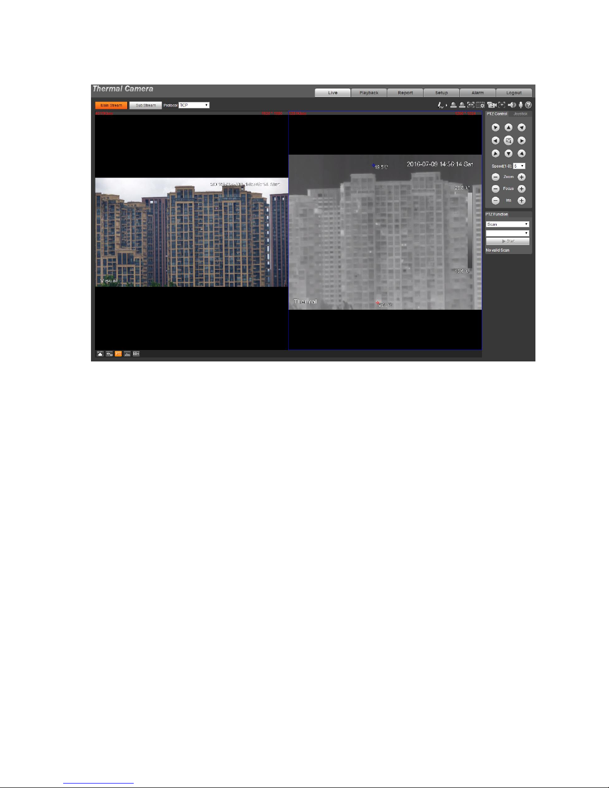
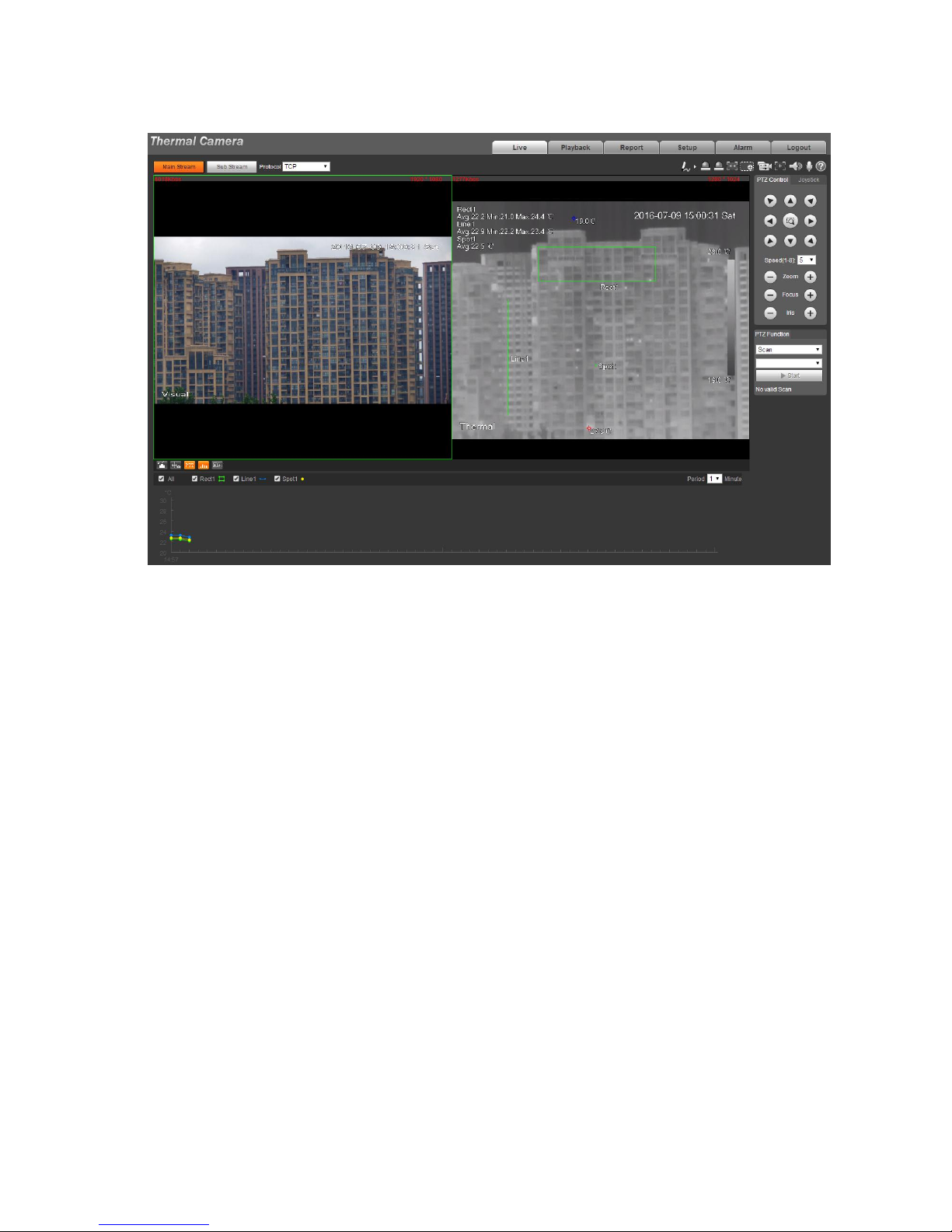
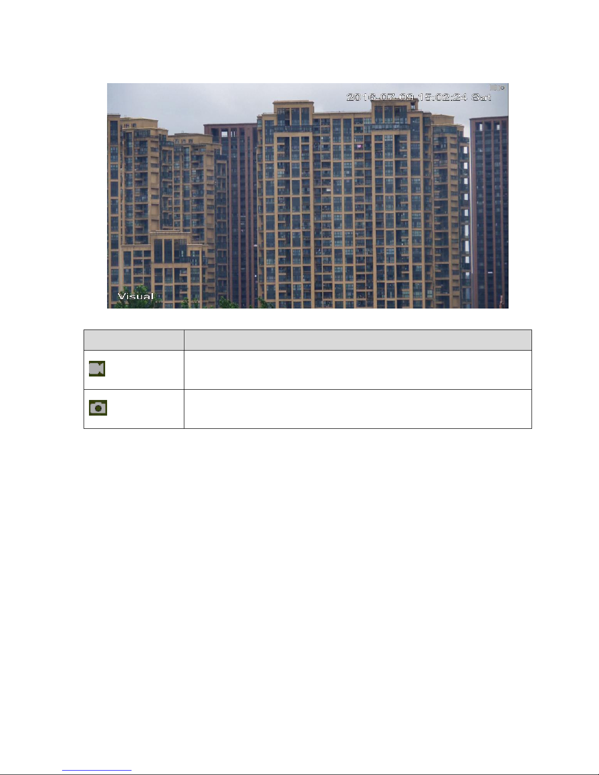
2 Live
You can implement a series of operations upon the realtime monitoring image in the “Live” interface,
such as live, snapshot and record etc.
Click “Live” and the system will display the interface which is shown in Figure 2-1.
Note:
There is some difference about the function and interface for different devices, please refer to the
actual interface for more details.
The live interface with a green box is the channel image which is currently chosen, therefore, all the
operations are only valid to the currently chosen channel.
Double click the image and the channel image will cover the whole video display area, double click
again and the channel image will be displayed in full screen. Click the right mouse button to exit full
screen.
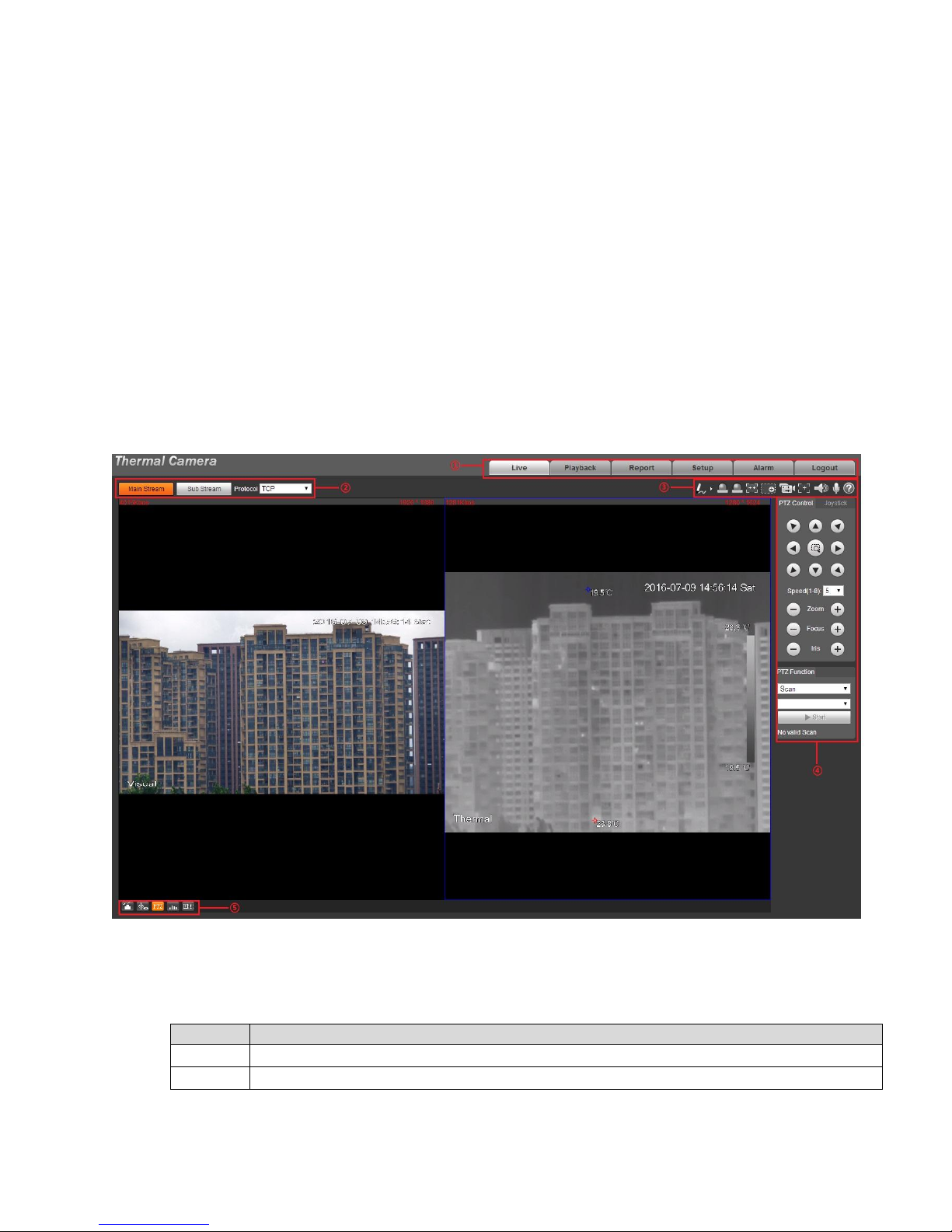
Figure 2-1
The live interface of WEB client includes four functions, which is shown in sheet 2-1.
SN
Note
①
System menu bar, click each module and enter the corresponding config interface.
②
Encode setup bar, the description of each stream is as follows:
Page 10
5
Main Stream, big stream, high image definition, but it occupies big bandwidth,
which can be applied for storage and monitoring.
Sub Stream, smaller stream compared to main stream, smooth image, it
covers small bandwidth,which can be applied to replace main stream for
monitoring when network bandwidth is not enough.
Protocol, network transmission protocol type, which supports TCP, UDP and
multicast.
③
Video window function option bar, please refer to “2.1 Video Window Function
Option” for more details.
④
PTZ control bar, please refer to “3. PTZ” for more details.
Note:
As for bullet PTZ control bar, it needs to click “PTZ module” to enter.
⑤
Video window adjustment bat, please refer to “2.2 Video Window Adjustment” for
more details.
Sheet 2-1
2.1 Video Window Function Option
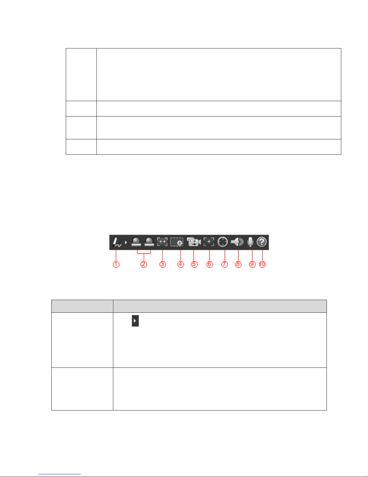
The video window function option is shown in Figure 2-2.
Note:
There is slight difference about function and interface between different devices, please refer to the
actual interface for more details.
Figure 2-2
Please refer to sheet 2-2 for more details about the parameters.
Parameter
Note
① Remark
Click and select color, you can write remark in the live image.
There are three colors to be selected, which are green, blue and red, it
is red by default.
Note:
It won’t display remark in the record image.
② Relay-out1
Relay-out2
It is to display if there is alarm output.
Red: It means outputting alarm.
Gray: It means alarm is over.
Click the button to enable or disable alarm.
Page 11

6
Parameter
Note
③ Fixed Focus
Click the button and the visual can be adjusted to corresponding view
angle according to the thermal zoom rate.
④ Digital Zoom
Click the button to select digital zoom of visual or thermal, click the
right mouse button to recover the original status.
Click the button to zoom in or out the image size via rolling the
mouse wheel.
⑤ Record All
Click the button and it can record in both visual and thermal channel at
the same time, the video is stored to the set storage path. Please refer
to “6.1.2.5 Storage Path” for storage path setting.
Note:
If you want to playback either of the recorded video, it has to play both
videos at the same time (visual and thermal).
⑥ Easy Focus
Click the button and you can see two parameters of AF Peak and AF
Max in the live video.
AF Peak: The value realtime displays the eigenvalue of image
resolution during focus.
AF Max: The value means the best eigenvalue of image resolution.
The closer the AF Peak value and AF Max get, the better the effect
becomes.
⑦ Manual Track
Click the button and drag the left mouse button on the live interface and
select the tracking target, then the system will auto track the selected
target.
Note:
It needs to select tracking mode before using the function, please refer
to “6.4.1.4 smart track” for more details.
⑧ Audio
Click the button to enable or disable audio output of the monitoring
interface.
Note:
The function is supported only by devices with audio function.
⑨ Talk
Click the button and enable or disable talk function. Please turn off
stereophonic mixing on the computer when enabling talk function.
Note:
The function is only supported by the devices with audio
⑩ Help
It is to open help document.
Sheet 2-2
Page 12
7
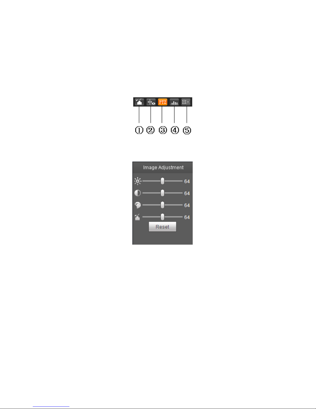
2.2 Video window Adjustment
See Figure 2-3 and Figure 2-4 for the video window adjustment function.
Note:
Different devices may have difference about function, and there is some difference about interface,
please refer to the actual interface for more details.
Figure 2-3
Figure 2-4
Please refer to the following sheet for detailed information.
Page 13
8
Parameter
Note
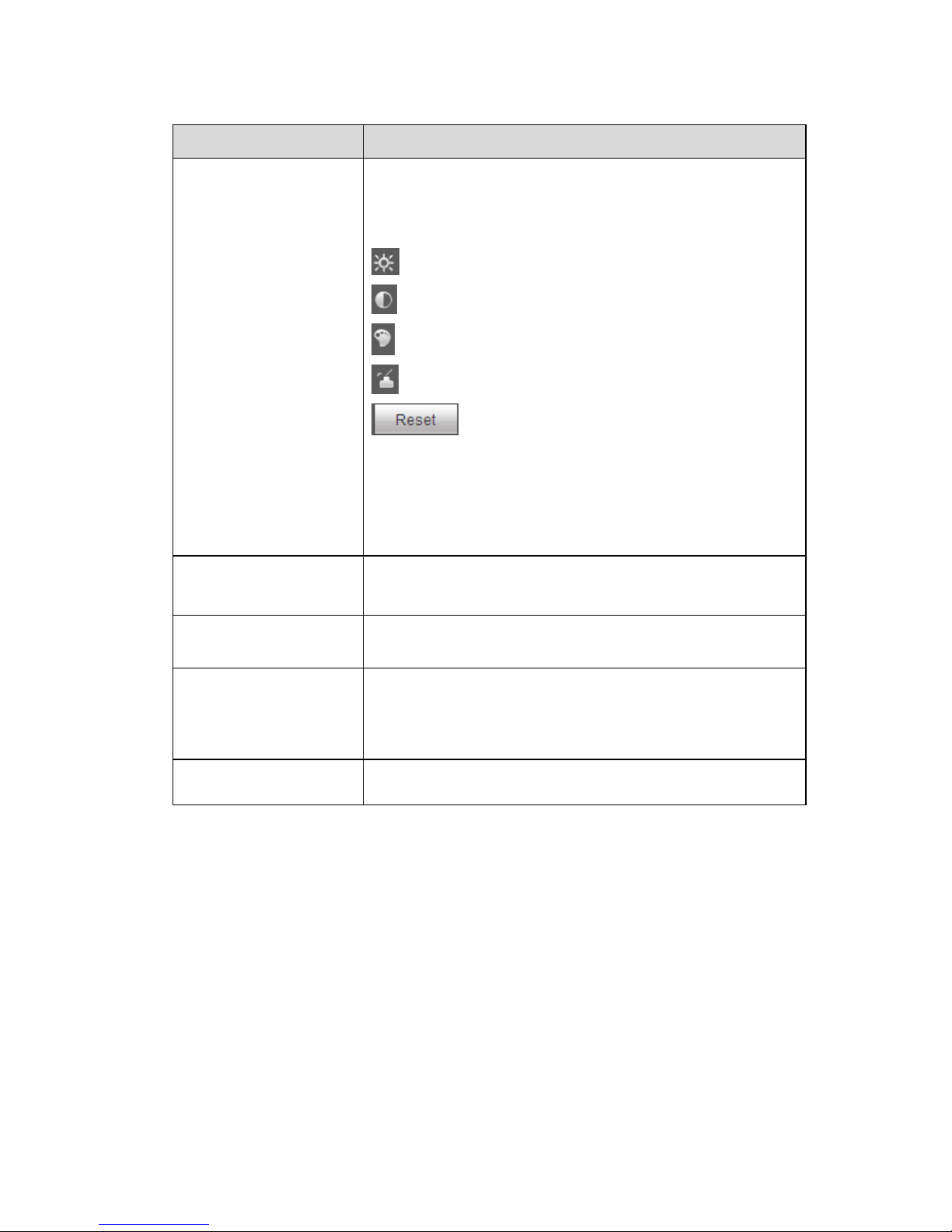
① Image adjustment
Click image adjustment button, you can see the image
adjustment interface on the right of preview interface,
see Figure 2-4, click left mouse button to adjust image
config.
: It is to adjust monitor video brightness.
: It is to adjust monitor video contrastness.
: It is to adjust monitor video hue.
: It is to adjust monitor video saturation.
: Restore brightness, contrastness, saturation
and hue to system default setup.
Note:
All the operations here apply to WEB end only.
Please go to Setup->Camera->Conditions to adjust
corresponding items.
② Rules info
Click the button, it is to display intelligent rule on the
preview page after enabled, it is enable by default.
③ PTZ
Enable or disable PTZ interface. Click left mouse button
to display or hide PTZ control interface.
④ Realtime report
It is to enable or disable realtime report interface, it
mainly records the temperature change of selected spot,
line and area during appointed time period starting from
the current time, see Figure 2-9
⑤ Ray axis correct
Enable or disable ray axis correct
Sheet 2-3
Page 14
9
Figure 2-5
2.3 More Functions
The live interface also supports local record, capture and realtime spot temperature measurement.
2.3.1 Local Record and Capture
Move the mouse to the top right corner of the live interface, the system will display the icons of local
record and capture, which is shown in Figure 2-6.
Page 15
10
Figure 2-6
Parameter
Note
Local record
Click the button to record video; store it in the storage path which has
been set. Please refer to “6.1.2.5 Storage Path” for the setting of
storage path.
Capture
Click the button to enable video capture function, the picture will be
stored into the storage path which has been set. Please refer to “6.1.2.5
Storage Path” for the setting of storage path.
Sheet 2-4
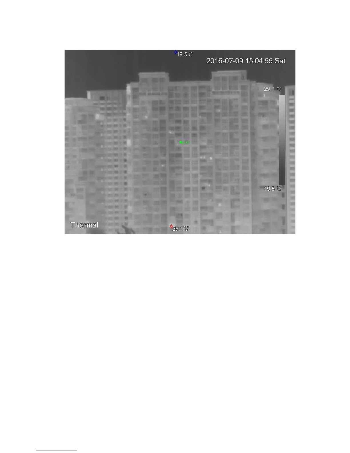
2.3.2 Realtime Spot Temperature Measurement
Note:
The function is available for the device which is equipped with temperature measurement, please refer
to the actual interface for more details.
Move the mouse to any location on the live interface, and the system will display the realtime
temperature of the location, which is shown in Figure 2-7.
Page 16
11
Figure 2-7
2.3.3 Laser Ranging
Note:
The function is available for the device which is equipped with ranging function; please refer to the
actual interface for more details.
Click “Start” and it will measure the distance between the camera and the image center (marked by red
cross), which is shown in Figure 2-8.
Page 17

12
Figure 2-8
Page 18
13
3 PTZ
3.1 Bullet Camera
Note:
The PTZ setting of the bullet camera is used to control external PTZ device, please connect to external
PTZ via RS485 port before using the function, otherwise the function will be invalid.
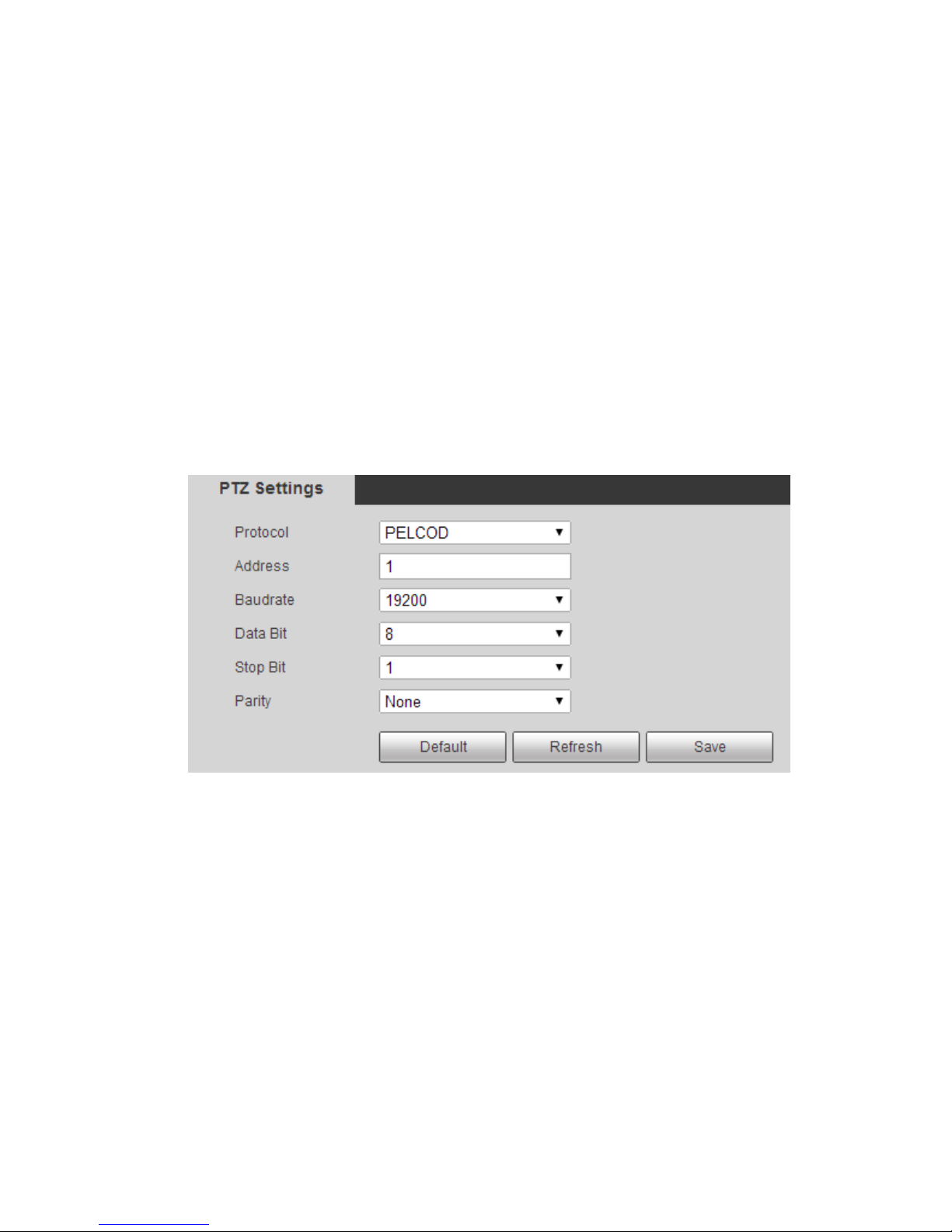
3.1.1 Setting Protocol
It needs to connect camera to external PTZ via setting protocol first when the bullet camera needs to
control external PTZ.
Step 1
Select “Setup > System > PTZ Setting”. The system will display the interface of “PTZ Setting” ,which is
shown in figure 3-1.
Figure 3-1
Step 2
Set the parameters of PTZ protocol, click “Save” to complete config. Please refer to sheet 3-1 for more
details about the parameters.
Page 19
14
Parameter
Note
Protocol
Match the PTZ protocol
Address
It is set as corresponding device address.
Note:
The address has to be in accordance with that of external PTZ,
otherwise it won’t control external PTZ.
Baud Rate
It is to select baud rate used by device.
Data Bit
The default is 8.
Stop Bit
The default is 1.
Parity
The default is null.
Sheet 3-1
3.1.2 Setting Function
Note:
It has completed protocol setting. Please refer to “3.1.1 Setting Protocol” for more details of
protocol setting.
PTZ setting operates external PTZ, check the effect in the preview image of external PTZ but not in
the preview image of bullet camera.
The following functions are valid only when external PTZ is supported.
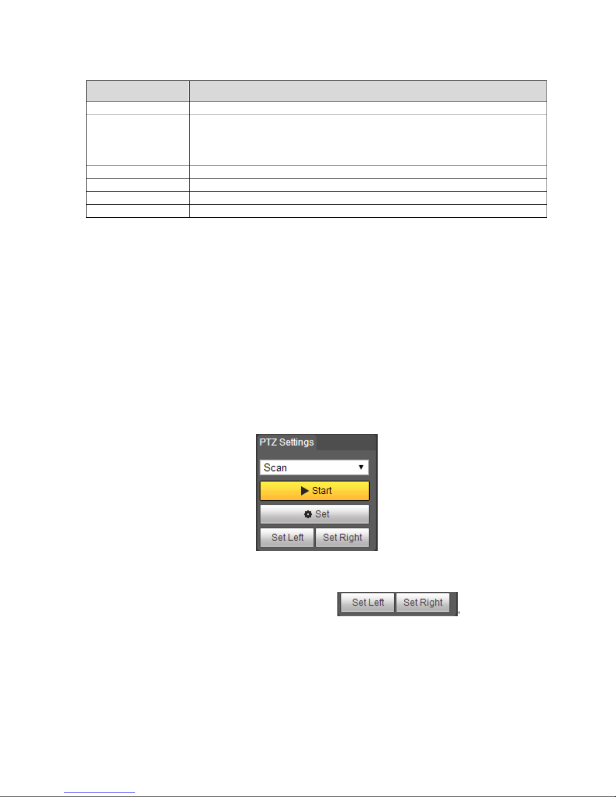
3.1.2.1 Scan
Scan means the camera scanning from left limit to right limit with a certain speed.
Step 1
Click “PTZ” and select the rule as “Scan” in “PTZ Setting” area, which is shown in Figure 3-2.
Figure 3-2
Step 2
Click “Set” button and the system will display the icon of .
Step 3
Move to the left limit via direction button, click “Set Left” to cnfirm the location of left limit.
Step 4
Move to the right limit via direction button, click “Set Right” to confirm the location of right limit.
So far, you have completed the path setting of scan.
Page 20
15
3.1.2.2 Preset
Preset means the environment where the camera is located, it can quickly adjust PTZ and camera to
the environment via calling preset.
Step 1
Click “PTZ” and select the rule as “Preset” in “PTZ Setting” area, which is shown in Figure 3-3.
Figure 3-3
Step 2
Input preset value into the box of preset.
Step 3
Click “Go to” and the camera will move to the corresponding location of the preset.
Step 4
Move the camera to the needed location via direction button, enter the preset value into the box of
preset.
Step 5
Click “Add” to set the next preset, the range of preset is related to the exact PTZ protocol.
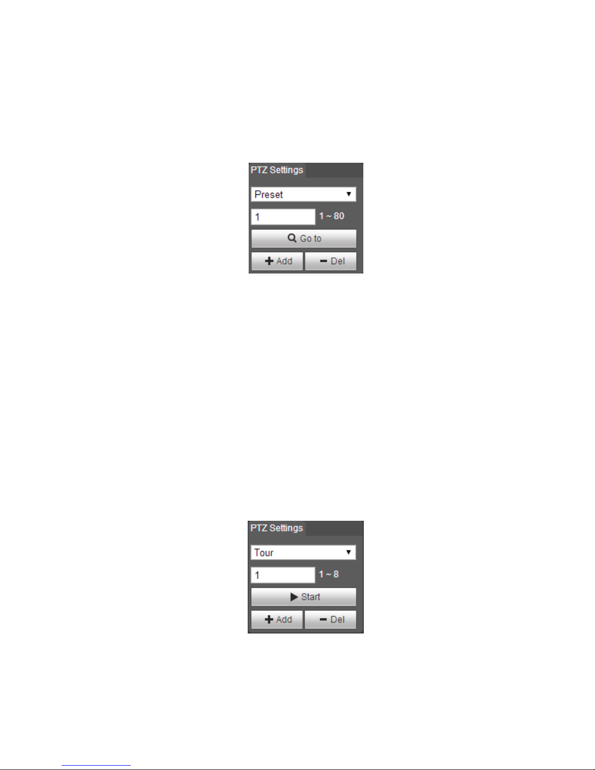
3.1.2.3 Tour
Tour means auto movement according to the presets which have been set.
Step 1
Click “PTZ” and select the rule as “Tour” in the “PTZ Setting” area, which is shown in Figure 3-4.
Figure 3-4
Step 2
Enter tour value in the box of tour.
Page 21
16
Step 3
Click “Add” and the setting range is related to the exact PTZ protocol.
Stpe 4
Enter the preset value in the box of preset.
Step 5
Click “Add” to add a preset in the tour path. Click “Del” to delete the preset in the tour path.
Note:
It can add several presets and also can delete the presets which have already existed in the tour.
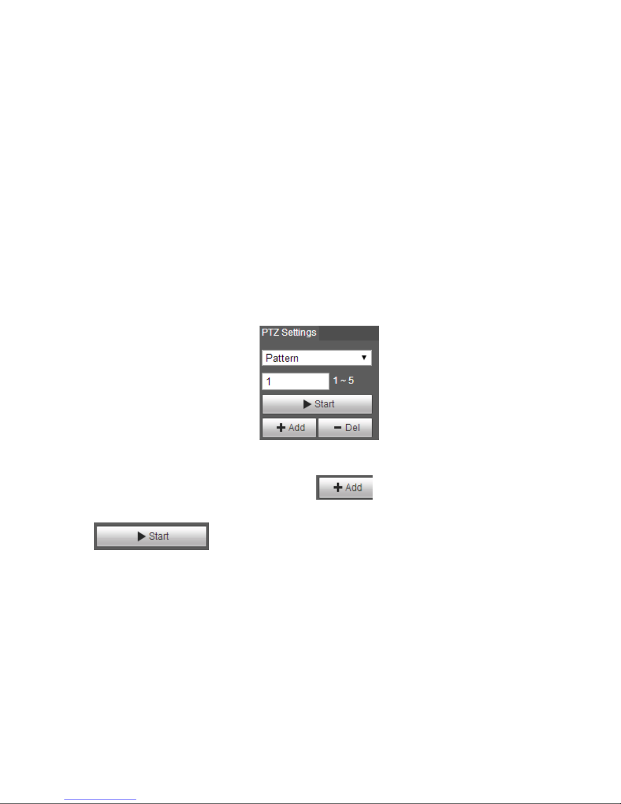
3.1.2.4 Pattern
Pattern can continuously record the camera operations implemented by users such as pan, tilt, zoom
and preset etc. You can directly call the pattern path after it is recorded and saved.
Step 1
Click “PTZ” and select the rule as “Pattern” in “PTZ Setting”, which is shown in Figure 3-5.
Figure 3-5
Step 2
Enter the pattern number in the box of pattern, click .
Step 3
Click to implement a series of operations such as zoom, focus, iris and direction
etc.
Step 4
Click “Stop” to complete the setting of a pattern path.
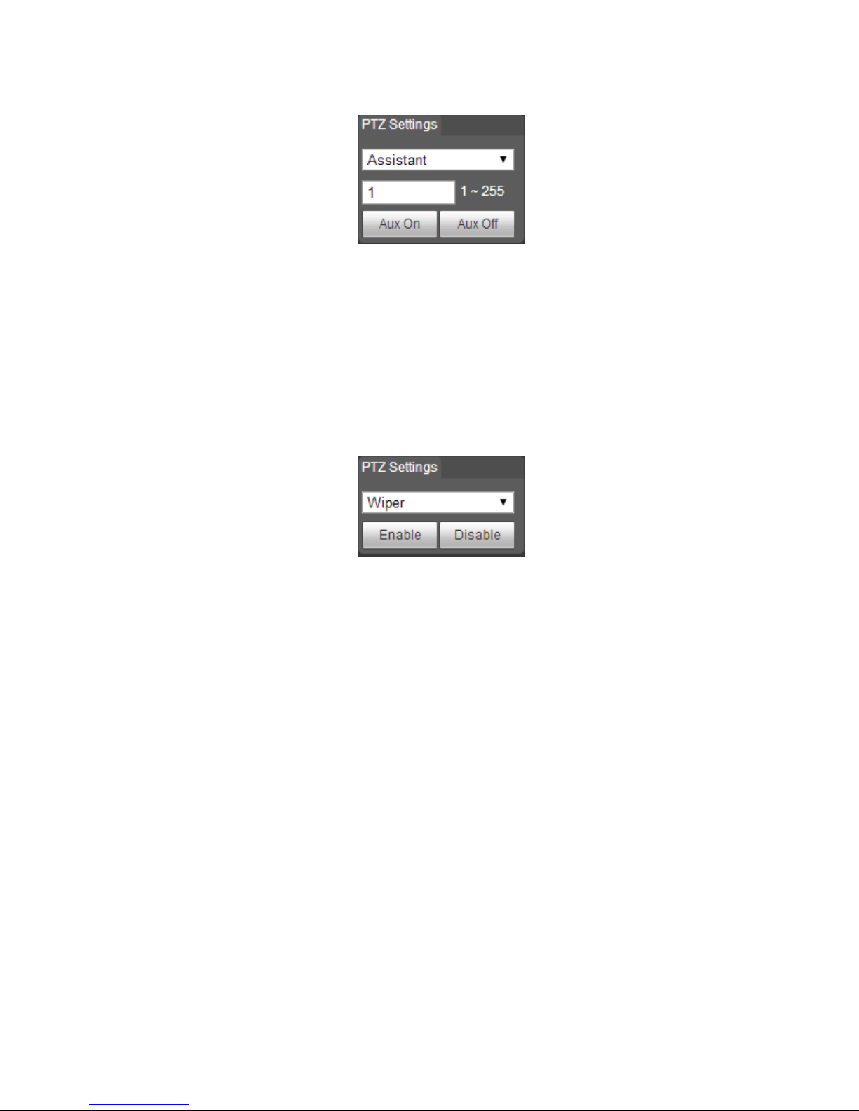
3.1.2.5 Assistant
Step 1
Click “PTZ” and select the rule as “Assistant” in the “PTZ Setting” area, which is shown in Figure 3-6.
Page 22
17
Figure 3-6
Step 2
Enter the value of assistant function in the box of assistant.
Step 3
Click “Aux On” to enable the corresponding assistant functions.
3.1.2.6 Wiper
Step 1
Click “PTZ” and select the rule as “Wiper” in the “PTZ Setting” area, which is shown in Figure 3-7.
Figure 3-7
Step 2
Click “Enable” to enable wiper function.
3.1.3 PTZ Control
Note:
Users need to complete “3.1.1 Setting Protocol” and “3.1.2 Setting Function” before using PTZ
control.
The PTZ control of bullet operates the external PTZ, you can check the result in the live interface of
external PTZ but not in the live interface of the bullet.
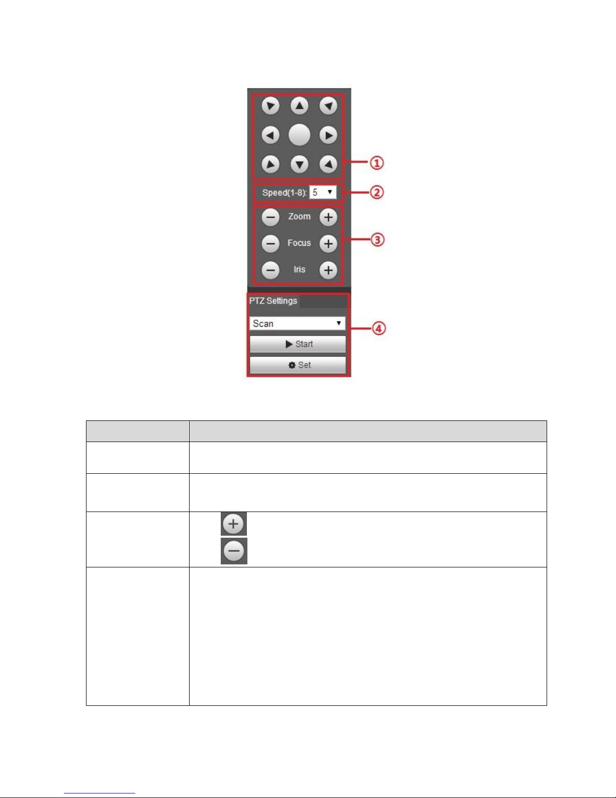
Click “PTZ” and the PTZ control is on the right of “PTZ” interface, which is shown in Figure 3-8.
Page 23
18
Figure 3-8
Parameter
Note
①Direction button
It supports 8 directions, which are up, down, left, right, upper left, upper
right, lower left, lower right.
②Speed
It is mainly used to operate speed, the longer the step is, the faster the
Speed becomes. The speed is valid to PTZ direction control, zoom, focus
And iris adjustment.
③Zoom, Focus ,Iris
Click and the cooresponding parameter becomes bigger,
Click and the corresponding parameter becomes smaller.
④PTZ Function
The supported PTZ functions include:
Scan
Select scan number, click “Start” to make PTZ scan.
Preset
Select preset number, click “Go to” and the camera moves to the
corresponding location of the preset.
Tour
Select tour number, click “Start” to begin tour.
Pattern
Select pattern number, click “Start” to begin pattern.
Assistant
Page 24
19
Parameter
Note
Reserve extended functions.
Wiper
Click “Enable” to enable wiper function.
Sheet 3-2
3.2 Speed Dome and PTZ
3.2.1 Setting Protocol
When external devices (such as NKB, NVR) want to control speed dome or PTZ devices, first it needs
to make the external device connect to PTZ via setting protocol. Please select protocol according to the
practical situation, please refer to “3.2.1.1 Network PTZ Setting” to config if it is to adopt network
protocol, please refer to “3.2.1.2 Analog PTZ Setting” to config if it is to adopt analog protocol.
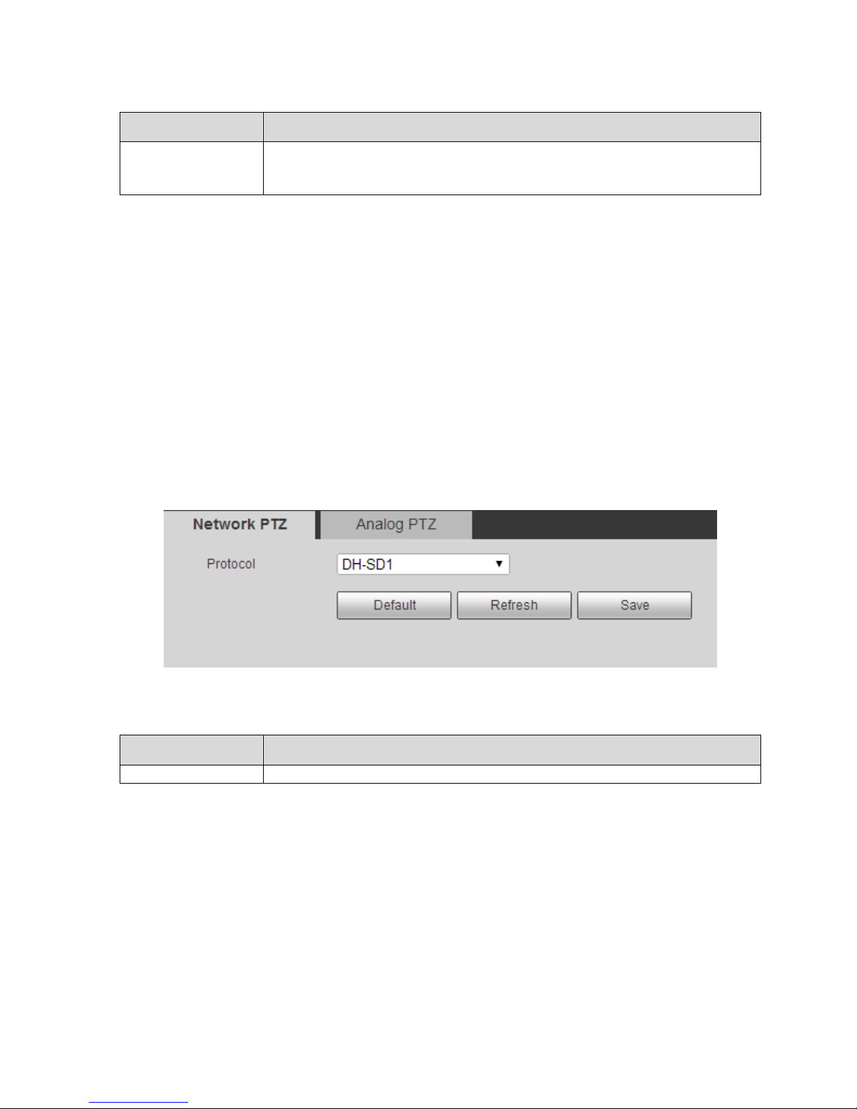
3.2.1.1 Network PTZ Setting
Step 1
Select “Setup > PTZ Setup > Protocol > Network PTZ Setting”. The system will display the interface of
“Network PTZ Setting”, which is shown in Figure 3-9.
Figure 3-9
Step 2
Select protocol, click “Save” to complete config. Please refer to sheet 3-3 for more details.
Parameter
Note
Protocol
Match the protocol of the connected device.
Sheet 3-3
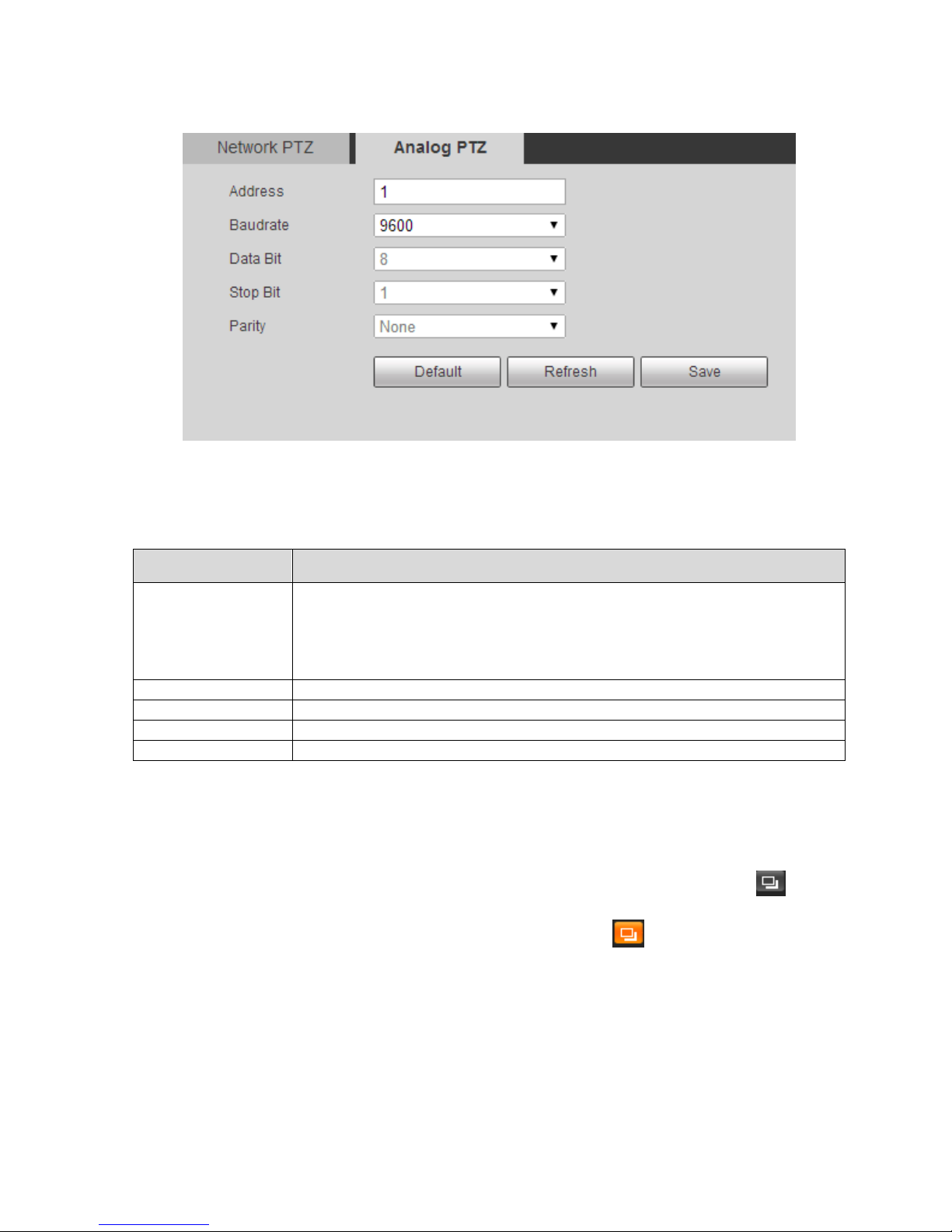
3.2.1.2 Analog PTZ Setting
Step 1
Select “Setup > PTZ Setup > Protocol > Analog PTZ Setting”. The system will display the interface of
“Analog PTZ Setting”, which is shown in Figure 3-10.
Page 25
20
Figure 3-10
Step 2
Set the parameters of PTZ protocol, click “Save” to complete config. Please refer to sheet 3-4 for more
details.
Parameter
Note
Address
It is to set the corresponding device address.
Note:
If it is to connect to external keyboard and etc, then the address has to
be in accordance with that of the keyboard, otherwise it will fail to
control PTZ via external keyboard.
Baud rate
Select the baud rate used by device.
Data Bit
The default is 8.
Stop Bit
The default is 1.
Parity
The default is null.
Sheet 3-4
3.2.2 Setting Function
Note:
Select “Setup > PTZ Setting > Function” and enter the interface of function setting, click in the
thermal monitoring image, then the image is switched to visual; click in the visual monitoring image,
then the image is switched to thermal.
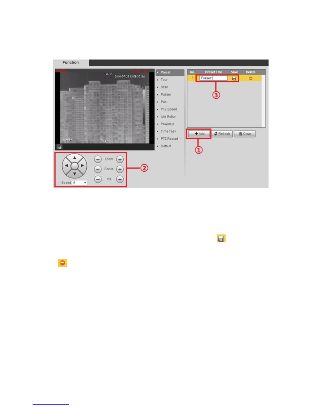
3.2.2.1 Preset
It is to quickly adjust the PTZ and camera to save location via calling preset.
Step 1
Page 26
21
Select “Setup > PTZ Setting > Function > Preset”. The system will display the interface of “Preset”,
which is shown in Figure 3-11.
Figure 3-11
Step 2
Set preset.
1. Click “Add’” to add a new preset.
2. Control PTZ direction, zoom, focus and iris; adjust the camera to proper monitoring spot.
3. Double click the title of the added preset to modify the name, and click to save config.
Note:
Click to delete config error or the preset which is no longer needed.
Click “Clear” to delete all the added presets.
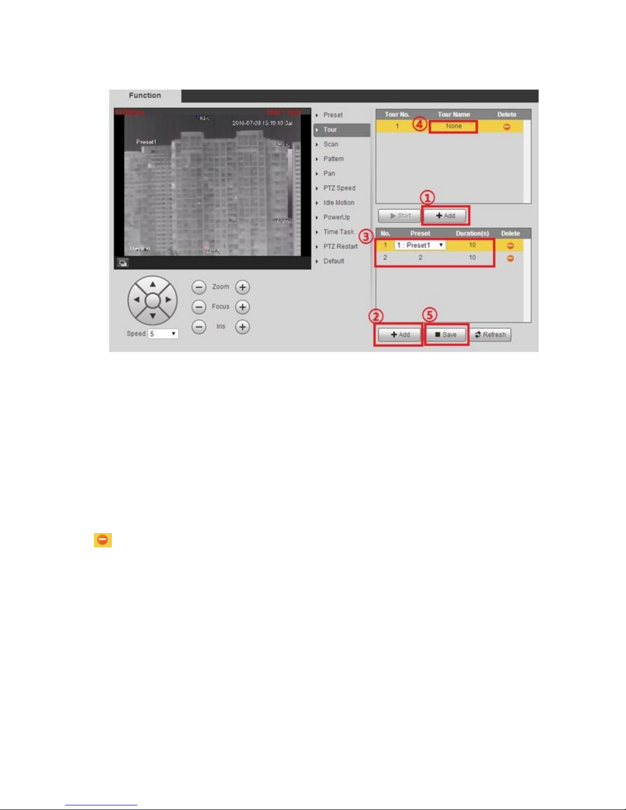
3.2.2.2 Tour
It means auto movement according to the preset which has been set. It has to complete preset setting
before setting tour.
Step 1
Select “Setup > PTZ Setting > Function > Tour”. The system will display the interface of “tour”, which is
shown in Figure 3-12.
Page 27
22
Figure 3-12
Step 2
Set tour.
1. Click “Add” to add a new tour.
2. Click “Add” to add preset. Click repeatedly to add several presets.
3. Double click to select preset, and double click to set duration.
4. Double click tour name and modify the name.
5. Click “Save” to save the config.
Note:
Click to delete corresponding tour and preset.
Step 3
Select tour, click “Start” to begin tour, the button is switched to “Stop”, click again to stop tour.
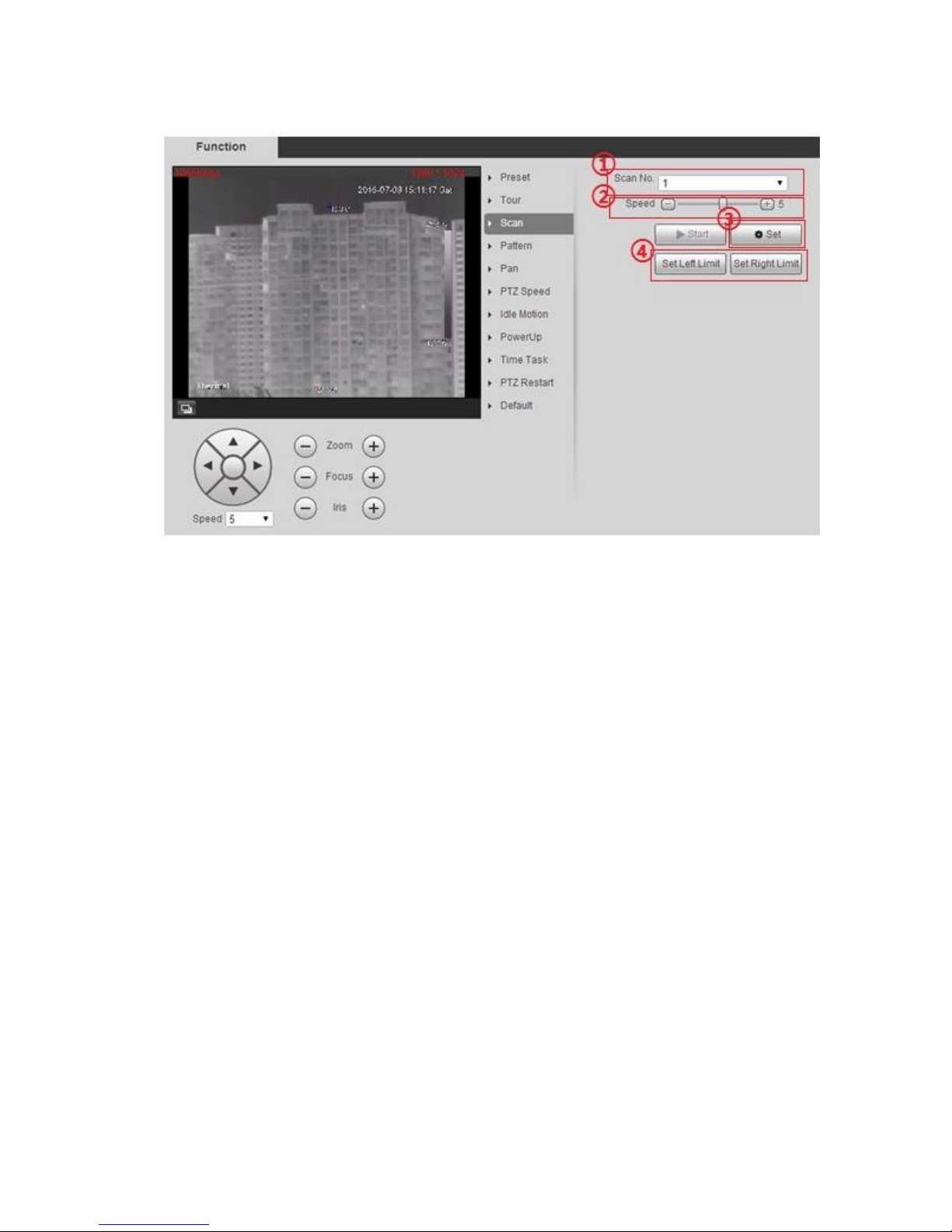
3.2.2.3 Scan
It means camera sanning within the range from left limit to right limit with a certain speed.
Step 1
Select “Setup > PTZ Setting > Function > Scan”. The system will display the interface of “Scan”, which
is shown in Figure 3-13.
Page 28
23
Figure 3-13
Step 2
Set scan.
1. Select scan number.
2. Set scan speed.
3. Click “Set” to export control button.
4. Export control button, adjust the camera to proper monitoring location, click “Set Left Limit”, continue
to adjust the camera monitoring location, click “Set Right Limit” when it is in proper location.
Step 3
Click “Start’ to enable scan, the button is switched to “Stop”, click again to stop scan.
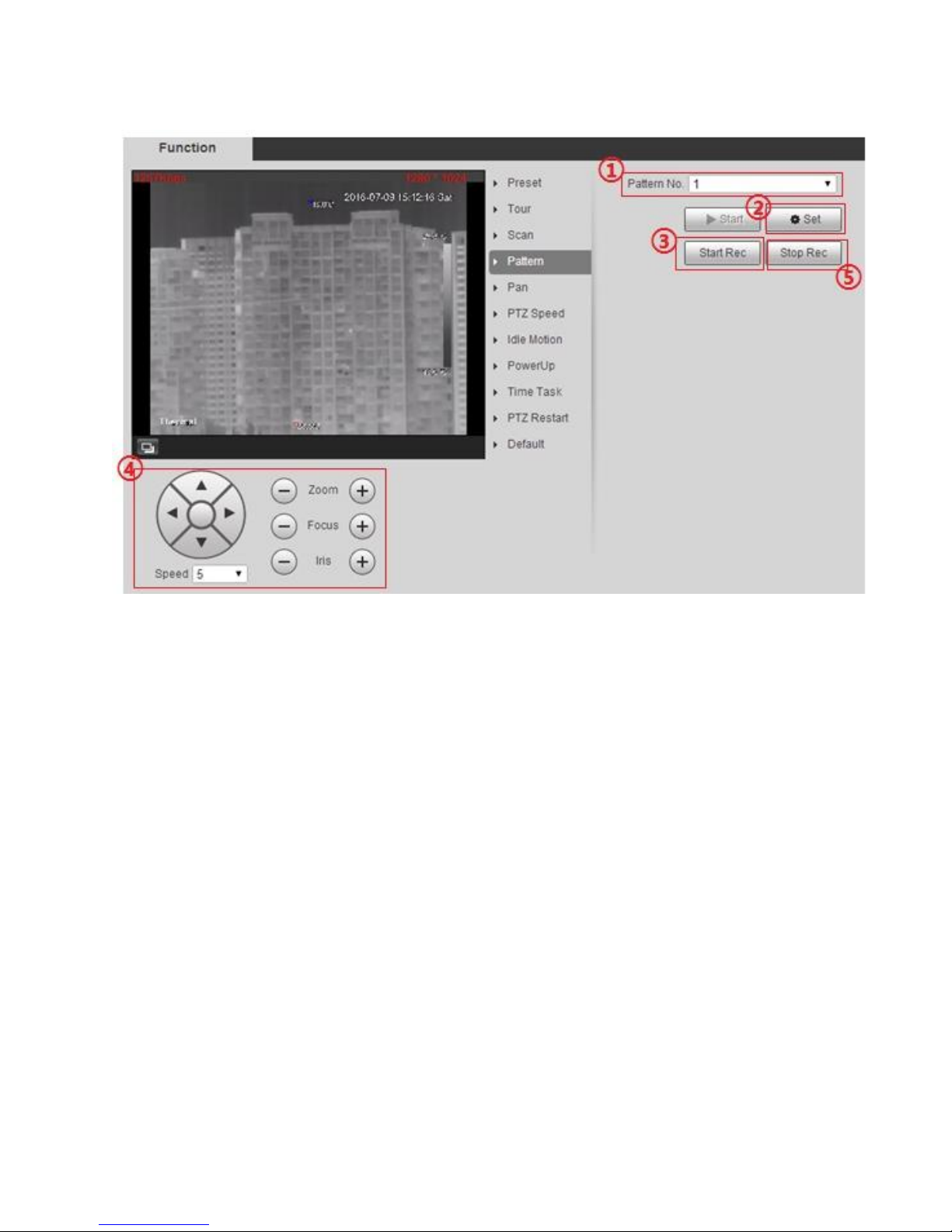
3.2.2.4 Pattern
It can continuously record the camera pan, tilt, zoom and preset call etc. You can directly call the
pattern path after recording and saving is completed.
Step 1
Select “Setup > PTZ Setting > Function > Pattern”. The system will display the interface of “Pattern”,
which is shown in Figure 3-14.
Page 29
24
Figure 3-14
Step 2
Set pattern.
1. Select pattern number.
2. Click “Setup” to export config button.
3. Click “Start Rec” to record operations.
4. Implement a series of operations such as zoom, focus, iris and direction etc.
5. Click “Stop Rec” to stop record.
Step 3
Select pattern number, click “Start” to begin pattern, the button will be switched to “Stop”, click “Stop”
again to stop pattern.
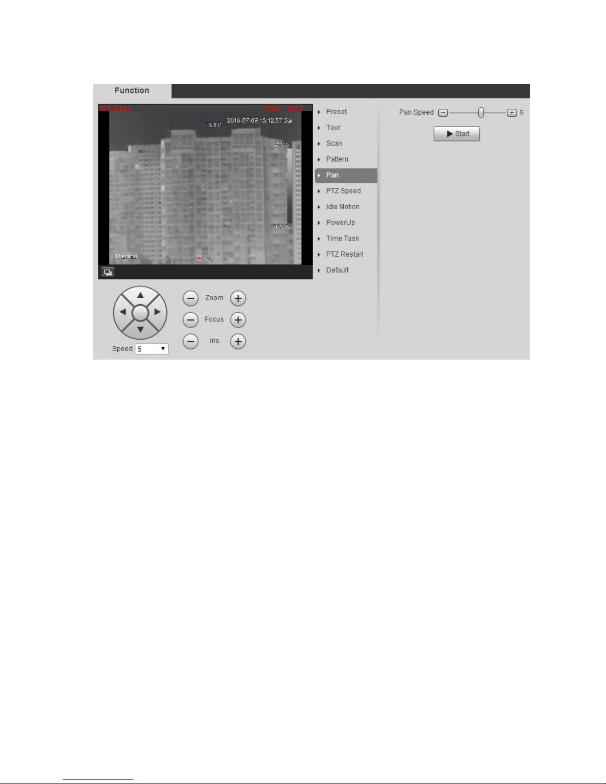
3.2.2.5 Pan
Pan means 360°endless rotation with a certain speed for the camera PTZ.
Step 1
Select “Setup > PTZ Setting > Function > Pan”. The system will display the interface of “Pan”, which is
shown in Figure 3-15.
Page 30
25
Figure 3-15
Step 2
Set rotation speed, click ‘Start” and the camera PTZ will start pan, the button will be switched to “Stop”,
click again to stop pan.
3.2.2.6 PTZ Speed
PTZ speed means the rotation speed of the camera PTZ.
Step 1
Select “Setup > PTZ Setting > Function > PTZ Speed”. The system will display the interface of “PTZ
Speed”, which is shown in Figure 3-16.
Page 31

26
Figure 3-16
Step 2
Select PTZ speed, and complete config.
3.2.2.7 Idle Motion
Idle motion means the camera PTZ implements the action which was set in advance it receives no valid
orders within the specified period. Please make sure the selected action has completed config before
setting idle motion.
Step 1
Select “Setup > PTZ Setting > Function > Idle Motion”. The system will display the interface of “Idle
Motion”, which is shown in Figure 3-17.
Page 32

27
Figure 3-17
Step 2
Set idle motion.
1. Select “Enable”.
2. Select idle motion and its corresponding number, set idle time.
3. Click “Save” to complete setting.
3.2.2.8 Power up
It means the auto movement after the camera is powered up.
Step 1
Select “Setup > PTZ Setting > Function > Power up”. The system will display the interface of “Idle
Motion”, which is shown in Figure 3-18.
Page 33

28
Figure 3-18
Step 2
Set powerup.
1. Select “Enable”.
2. Select idle motion and its corresponding number.
Note:
The system will operate the last motion before power off when selecting ‘Auto”.
3. Click ‘Save” to complete setting.
3.2.2.9 Time Task
It means implementing related actions within the specified period.
Step 1
Select “Setup > PTZ Setting > Function > Time Task”. The system will display the interface of “Time
Task”, which is shown in Figure 3-19.
Page 34

29
Figure 3-19
Step 2
Set time task.
1. Select “Enable”.
2. Select “Time task Number.”
3. Select “Time task action” and “Action number”.
4. Set the period of auto home.
The auto home period means the time needed for auto restore to time task when manually calling PTZ
and interrupting time task.
5. Set period for time task.
6. Select new task number; click “Copy” to copy the time task information to its corresponding time
task number.
7. Click ‘Save”.
3.2.2.10 PTZ Restart
Manually restart the PTZ
Step 1
Select “Setup > PTZ Setting > Function > PTZ Restart”. The system will display the interface of “PTZ
Restart”, which is shown in Figure 3-20.
Page 35

30
Figure 3-20
Step 2
Click “PTZ Restart” to restart the PTZ.
3.2.2.11 Default
Attention:
The function will delete all the configurations made by users, please confirm first and then operate.
Step 1
Select “Setup > PTZ Setting > Function > Default”. The system will display the interface of “Default”,
which is shown in Figure 3-21.
Page 36

31
Figure 3-21
Step 2
Click “Default” and the PTZ will restore its default config.
3.2.3 PTZ Control
Note:
Users need to complete “3.2.1 Setting Protocol” and “3.2.2 Setting Function” before using PTZ control.
Click on the live interface to display the control panel of the PTZ, which is shown in Figure 3-22.
Page 37

32
Figure 3-22
Parameter
Note
①Quick position
Quick position function. Use the mouse to draw a box in the monitoring
image, and the PTZ will quickly rotate and zoom to the scene.
②Direction button
Support 8 directions, which are up, down, left, right, upper left, upper
right, lower left and lower right.
③Speed
It is mainly used for speed operation, the bigger the speed is, the faster
it becomes. The speed is valid to PTZ direction control, zoom, focus
and iris adjustment.
④Zoom, focus, iris
Click and corresponding parameter value becomes bigger, click
and correspoding parameter value becomes smaller.
Page 38

33
Parameter
Note
⑤PTZ function
The supported PTZ functions include:
Scan
Select scan number, click “Start” to make PTZ scan.
Preset
Select preset number, click “Go to” and the camera moves to the
corresponding location of the preset.
Tour
Select tour number, click “Start” to begin tour.
Pattern
Select pattern number, click “Start” to begin pattern.
Assistant
Reserve extended functions.
Wiper
Click “Enable” to enable wiper function.
Quick position
Input the needed horizontal and vertical angle, click “Quick
position” to accurately locate some spot.
Sheet 3-5
Page 39

34
4 Playback
It can playback the saved video or picture in the playback interface.
Note:
It needs to refer to period setting of record and snapshot, storage mode and record control in “6.7
Storage Management”.
Some devices may not have playback function, please refer to the actual interface.
Different devices may have different functions and interfaces, please refer to the actual interface.
Click “Playback” and the system will display the interface of ‘Playback”, which is shown in Figure 4-1.
Figure 4-1
4.1 Video Playback
It is to play captured video according to the needs.
Select the file type as “dav” and the system will display the interface of video playback, which is shown
in Figure 4-2.
Page 40

35
Figure 4-2
The video playback interface of WEB client includes six functions, which is shown in sheet 4-1.
SN
Function
Note
①
Play control
Play control button, please refer to “4.1.1
Play Control” for more details.
②
Volume adjust
It is to control the volume during playback,
which includes the following two statuses.
, currently it is in a mute state.
, currently it is in a volume play
state, you can adjust the volume.
③
Record type
It includes four types which are general,
motion, alarm and manual, you can select
the record type to check according to
needs.
④
Progress bar
It is to display the record type and its
period.
Click some spot in the color area and it will
playback from that time.
Different record types have different colors,
please refer to the record type for more
details.
Page 41

36
⑤
Progress bar time format
It includes four time formats which are
, , and
. Take for example, it
means the whole progress bar is 24 hours.
⑥
Video clip
Clip some piece of video and save it.
Please refer to “4.1.3 Video Clip” for more
details.
⑦
Playback file
Hear you can select file type, data source
and record date etc.
Sheet 4-1
4.1.1 Play Control Bar
The function of play is shown as in Figure 4-3.
Figure 4-3
Parameter
Function
① Play
When you see this button, it means pause or not played record. Click this button,
switch to normal play status.
② Stop
Click this button to stop playing.
③ Play by
frame
Click this button to go to next frame.
Note:
You need to pause playback when you use this function.
④ Slow
Click on this button to play slowly.
⑤ Quick
Click on this button to play quickly.
Sheet 4-2
4.1.2 Playback Video
Video playback may be different according to different data source. Data source is divided into SD card
and local.
4.1.2.1 SD Card Video
Step 1
Select the record type which is to be checked in “Record Type Select Bar”, which is shown in Figure 4-4.
Page 42

37
Figure 4-4
Step 2
Select “File Type” as “dav” and select “Data Source” as “SD Card”, which is shown in Figure 4-5.
Figure 4-5
Parameter
Function
File Type
File type includes following two types:
“dav”, it means video playback.
“jpg”, it means picture playback.
Sheet 4-3
Step 3
Select “Channel” as “Visual” or “Thermal” according to needs.
Step 4
Select the year and month of the video to be checked, click the date in blue.
It will display the record file progress bar with color.
Note:
It displays the date with blue shading; it means there is record file for this date.
Different colors mean different record types on progress bar, please refer to Figure 4-4 for more details.
Step 5
Page 43

38
Play recorded video
Click the . The system will play the record file of the selected date (according to time sequence)
Click some spot on the progress bar (area with color), which is shown in Figure 4-6. The system will
play record file from that time.
Figure 4-6
Click file list option , the record file with selected date will be displayed in the list, double click the
file in the list.
The system will play the file and meanwhile display the file size, start time and end time. Please refer to
sheet 4-4 for more details.
Page 44

39
Figure 4-7
Parameter
Function
Search
Enter start time and end time, click .
Search all the record files between start time and end time.
Page 45

40
Parameter
Function
Download
Select “Record Type” as “dav” or “mp4”, click .
The file will be downloaded to the storage path which has been set. Please refer
to “6.1.2.5 Storage Path” for more dedetails.
Note:
The system does not support download and playback of MP4 file at the same
time.
Back
Click to go back to calendar interface.
Sheet 4-4
4.1.2.2 Local Video
Step 1
Select the record type which needs to be checked in “Record Type Column”, which is shown in Figure
4-8.
Step 2
Select “File Type” as “dav” and “Data Source” as “Local”.
The system will display the list of playback file, which is shown in Figure 4-8.
Page 46

41
Figure 4-8
Step 3
Double click file name. The system will play the file, which is shown in Figure 4-9.
Page 47

42
Figure 4-9
4.1.3 Video Clip
Clip some piece of video and save it to the storage path which has been set, which is shown in Figure
4-10.
Figure 4-10
Step 1
Select “Video Type” as “dav” or “mp4’.
Step 2
Click the start time of the clipped video on the progress bar, and then click to start clip.
Step 3
Click the end tiem of the clipped video and click to end clip.
Step 4
Click . The system will prompt that playback and download can’t be implemented at the same
time, which is shown in Figure 4-11.
Page 48

43
Figure 4-11
Step 5
Click “OK” and the system will close playback, save the clipped file into the storage path which has
been set. Please refer to “6.1.2.5 Storage Path” for more details.
4.1.4 Assistant Function
Move the mouse to top right corner of the video during video playback, then it will display assistant
function icon, which is shown in Figure 4-12.
Figure 4-12
Parameter
Note
Local
Click the button to record video and save it into the storage path which
has been set. Please refer to “6.1.2.5 Storage Path” for more details.
Snapshot
Click the button to take snapshot upon the playback video, the picture
will be saved into the storage path which has been set. Please refer to
“6.1.2.5 Storage Path” for more details.
Sheet 4-5
4.2 Picture Playback
It is to search and play snapshot pictures according to the needs.
Select “File Type” as “jpg”, the system will display the interface of “Picture Playback”, which is shown in
Figure 4-13.
Page 49

44
Figure 4-13
SN
Function
Note
①
Play control column
It includes the following two modes:
, default state icon, it means pausing or
not playing picture, click the button to play the
pictures.
, it means playing pictures; click the
button to stop playing.
It can be mutually switched between two states.
②
Snapshot type
It includes three types such as general, motion
and alarm. You can check the snapshot type
according to the needs.
③
Playback file column
Here you can select file type, snapshot date and
etc.
Sheet 4-6
Step 1
Select the snapshot type which needs to be checked in “Snapshot Type Column”, which is shown in
Figure 4-14.
Page 50

45
Figure 4-14
Step 2
Select “File Type” as “jpg”, which is shwon in Figure 4-15.
Figure 4-15
Parameter
Note
File type
It includes two types which are shown as follows:
“dav”, it means video playback.
“jpg”, it means picture playback.
Sheet 4-7
Step 3
Select “Channel” as “Visual” or “Thermal” according to the needs.
Step 4
Select the year and month of the video to be checked and the date with blue shading.
Note:
The date which displays blue shading means it has record file.
Step 5
Play picture
Click the . The system will play the pictures of the selected date (according to time sequence)
Page 51

46
Click file list option , the picture file of selected date will be displayed in the list, double click the
file in the list, which is shown in Figure 4-16.
The system will play the double-clicked file.
Figure 4-16
Page 52

47
Parameter
Function
Search
Enter start time and end time, click .
Search all the picture files between start time and end time.
Download
Click to download file to local.
Note:
The download operations are different by using different browsers, please refer to
the actual interface.
Back
Click to go back to calendar interface.
Sheet 4-8
Page 53

48
5 Report
The preconditions to make report function valid are as follows:
Users have set the rules of temperature measurement (including spot, line and area). Please refer
to “6.6.1 Rule Setup” if the rules of temperature measurement are not set.
The device has been inserted with SD card.
Note:
Some devices don’t have the function of report; please refer to the actual interface.
Step 1
Click “Report” and the system will display the interface of “Report”, which is shown in Figure 5-1.
Figure 5-1
Step 2
Set search condition, click “Search” and the system will display the searched temperature data, which is
shown in Figure 5-2.
Page 54

49
Figure 5-2
Page 55

50
6 Setup
Web client setup interface supports Camera, Network, Peripheral, Smart Thermal, Event, Temperature,
Storage, System and Information etc.
6.1 Camera
It is to set the camera, video and audio condition, which is to guarantee normal monitoring for the device.
6.1.1 Conditions
6.1.1.1 Visual
The interface mainly sets the visual image condition of the camera; adjust the image parameter to
realize optimal preview effect. The camera parameters are different due to different models; please refer
to the actual model for parameter setup.
Figure 6-1
Parameter
Note
Config file
It is to set the camera config mode, including normal, day and night.
Picture
It is to set the camera picture, including Brightness, Saturation, Chroma CNT,
Gamma, Sharpness, Sharpness CNT and so on
Page 56

51
Parameter
Note
Exposure
It is to set the camera exposure mode, including auto, manual, iris priority and
shutter priority.
Backlight
It is to set the camera backlight mode, including WDR, HLC and BLC.
WB
It is to set the camera WB mode, including auto, manual, ATW, outdoor, indoor,
outdoor auto, sodium lamp auto and sodium lamp.
Day & Night
It is to set the camera day & night mode, type includes electrical, ICR; mode includes
auto, black & white, color and Photoresistance.
Focus & Zoom
It is to set the zoom and focus mode of camera lens, for zoom, it can set digital zoom
and zoom speed, focus mode includes auto, manual and semi auto.
Defog
It is to set the picture defog mode, including Off and Auto.
Default
It is to restore the camera default setting.
Sheet 6-1
Picture
Step 1
Click “Picture” and the system will display the interface of “Picture”, which is shown in Figure 6-2
Figure 6-2
Step 2
Please configure each parameter info according to actual needs, please refer to sheet 6-2 for more details.
Page 57

52
Parameter
Note
Brightness
It is to set the image overall brightness, the bigger the value is, the brighter the
image will become.
Saturation
It is to set image color purity, it appears brighter with higher purity, and it appears
darker with lower purity.
Chroma CNT
It is to set the control degree of image color, the bigger the value is, the more
obvious the control becomes.
Sharpness
It is to adjust the sharpness degree of image edge. The bigger the value is, the
more obvious it becomes, it is opposite if the value is smaller. It may be easy for
image to generate noise if the value is set too big.
Sharpness
CNT Grade
It is to adjust the grade of sharpness control, the bigger the value is, the stronger
the control becomes.
Gamma
It is to set the image gamma value.
Mirror
It is to set left and right flip of the image.
Flip
The function can be used to change the direction of video monitoring. You can
select normal and inverted, it is normal by default.
Picture
Freeze
The image will directly skip to the image when the preset is called, it won’t display the
image during PTZ rotation.
Sheet 6-2
Step 3
Click “Save” to make the config valid.
Exposure
Step 1
Click “Exposure” and the system will display the interface of “Exposure”, which is shown in Figure 6-3.
Page 58

53
Figure 6-3
Step 2
Please configure info of each parameter according to actual needs; please refer to sheet 6-3 for more
details.
Parameter
Note
Anti-flicker
50Hz:When AC power is 50Hz, according to the scene brightness, auto
adjust exposure and ensure no cross stripe in the image.
60Hz:When AC power is 60Hz, according to the scene brightness, auto
adjust exposure and ensure no cross stripe in the image.
Outdoor: It can switch exposure mode under this mode, and realize the
effect of corresponding exposure mode.
Page 59

54
Parameter
Note
Exposure mode
It is to set the camera exposure mode, including auto/manual/iris priority/shutter
priority, see the details below:
In auto exposure mode, the image overall brightness can auto adjust within
normal exposure range according to different scene brightness.
In manual exposure mode, it can manually adjust gain value and shutter
value, besides it supports long exposure as well.
In iris priority mode, iris value is fixed, it can auto realize best brightness
according to the mode that it drives exposure time first and followed by
driving gain.
In shutter priority mode, the image overall brightness can auto adjust within
normal exposure range according to different scene brightness and
adjustment shutter range by priority. If image brightness is still not proper,
and meanwhile gain value has reached threshold, then auto adjust gain
value again to make the image normal.
Exposure Comp
Adjust the image brightness via adjusting brightness value of exposure target,
which is to apply to different scenes.
Slow Expo
It is to set the speed of exposure adjustment.
Gain upper limit
It is to limit the max gain of the camera.
Slow Shutter
In the low illuminance environment, it is to capture image via extending auto
exposure time, which can effectively reduce image noise, however, it may
generate smear for the mobile object; it is optional only in auto mode.
SS Limit
It is to limit the min shutter value of the camera.
AE Recovery
After manually adjusting “iris+”or “iris-”, recover back to the exposure mode
before adjustment regularly.
Basic NR
It is used to restrain noise, the higher the level is, the smaller the noise becomes,
and the image seems smooth than before.
Grade
Advanced NR
It is used to restrain noise, the higher the level is, the smaller the noise becomes,
and it may generate smear for mobile objects.
Grade
Sheet 6-3
Step 3
Click “Save” to make config valid.
Backlight
Step 1
Click “Backlight” and the system will display the interface of “Backlight”, which is shown in Figure 6-4.
Page 60

55
Figure 6-4
Step 2
Please configure info of each parameter according to actual needs; please refer to sheet 6-4 for more
details.
Parameter
Note
Mode
It supports four modes below:
BLC
In the environment with intense contrast between bright and dark, such as
backlighting environment, it will auto adjust image brightness to make the main
image clear to see.
HLC
It will auto adjust image brightness when there is quite intense light source in the
image, which is to improve the image influence caused by overexposure.
WDR
In the environment with intense contrast between bright and dark, auto adjust
image contrastness to make both bright area and dark area clear to see.
Self-adaptive
It can auto adjust image brightness according to environment, which is to make the
main image clear to see.
Sheet 6-4
Step 3
Click “Save” to make config valid.
Page 61

56
WB
Step 1
Click “WB” and the system will display the interface of “WB”, which is shown in Figure 6-5.
Figure 6-5
Step 2
Please configure info of each parameter according to actual needs; please refer to sheet 6-5 for more
details.
Parameter
Note
WB mode
It is to set the camera WB mode, which includes auto, manual, ATW, outdoor,
indoor, outdoor auto, sodium lamp auto and sodium lamp.
It can manually input red gain and blue gain value during manual mode.
Sheet 6-5
Step 3
Click “Save” to make config valid.
Day & Night
Step 1
Click “Day&Night” and the system will display the interface of “Day&Night”, which is shown in Figure 6-6.
Page 62

57
Figure 6-6
Step 2
Please configure info of each parameter according to actual needs; please refer to sheet 6-6 for more
details.
Parameter
Note
Type
It is to set the camera day & Night mode, including electrical and ICR.
Day&Night mode
It is to set the camera day & night mode, including black & white, color, auto and
Photoresistance.
Sensitivity
It is to set the day & night sensitivity.
Sheet 6-6
Focus & Zoom
Step 1
Click “Focus&Zoom” and the system will display the interface of “Focus&Zoom”, which is shown in Figure
6-7.
Page 63

58
Figure 6-7
Step 2
Please configure info of each parameter according to actual needs; please refer to sheet 6-7 for more
details.
Parameter
Note
Digital zoom
Select it to enable digital zoom function.
Zoom speed
It is to set camera zoom speed, the bigger the value is, the faster the zoom speed
will become.
Focus mode
It is to set camera focus mode, including auto, manual and semi auto.
Auto
Full auto mode, it will auto trigger focus if there is image moving or object changes
and image becomes blurry in the scene.
Semi-auto
Manually trigger focus, including pressing focus button, zoom trigger focus, preset
trigger focus, 3D position trigger focus and PTZ rotation trigger focus.
Manual
It the mode is selected as manual, then it won’t manually focus; it needs to click
and to manually focus to make the image clear.
Page 64

59
Focus limit
It is to set the camera focus distance, and avoid focusing on the enclosure due to
the too short focusing distance, meanwhile it can change focus speed via
changing focusing distance.
Sensitivity
It is to set the camera focusing sensitivity, it is easier to trigger focus with higher
sensitivity; on the contrary, and it will be harder to trigger focus with lower
sensitivity.
Sheet 6-7
Step 3
Click “Save” to make config valid.
Defog
Step 1
Click “Defog” and the system will display the interface of “Defog”, which is shown in Figure 6-8.
Figure 6-8
Step 2
Please configure info of each parameter according to actual needs; please refer to sheet 6-8 for more
details.
Page 65

60
Parameter
Note
Mode
It is to set the camera defog mode, you can select Auto and Off. It is Off by default
Intensity
It is to set the camera defog intensity; you can select low, medium and high. It is
medium by default.
Sheet 6-8
6.1.1.2 Thermal
It can set indoor, outdoor and general scene, it can set and check config and effect in corresponding
scene after selecting proper scene .
Step 1
Select “Setup > Camera > Conditions > Thermal” and the system will display the interface of “Thermal”,
which is shown in Figure 6-9.
Figure 6-9
Page 66

61
Step 2
Please configure info of each parameter according to actual needs; please refer to sheet 6-9 for more
details.
Parameter
Note
Preset
It is to select preset.
Scene
A package of video config parameter, which can be used for image optimization in
different scenes.
Page 67

62
Parameter
Note
Colorization
It is able to add color to the IR image, there are 14 colors to select:
White Hot:
In grayscale image, the place is brighter with higher temperature.
Black Hot:
In grayscale image, the place is brighter with lower temperature.
Fusion:
The color is concentrated within color range of purple-red-yellow; it becomes
purpler with lower temperature, and yellower with higher temperature.
Rainbow:
The color is concentrated within color range of blue-green-red-yellow; it becomes
bluer with lower temperature, and yellower with higher temperature.
Globow:
The color is concentrated within color range of red-yellow; it becomes redder with
lower temperature and yellower with higher temperature.
Ironbow 1:
The color is concentrated within color range of blue-purple-red-yellow; it becomes
bluer with lower temperature and yellower with higher temperature.
Ironbow 2:
Color distribution is close to Ironbow 1, but brightness is lower than Ironbow 1.
Sepia:
The main color is brown; the place with higher temperature becomes brighter.
Color 1:
The color is concentrated within color range of purple-red-yellow-green; it becomes
purpler with lower temperature, and bluer with higher temperature.
Color 2:
The color is concentrated within color range of blue-red-yellow; it becomes bluer
with lower temperature, and yellower with higher temperature.
Icefire:
The object with high temperature appears red in the color image, the object with
low temperature show blue. Generally it can be used as warning mode.
Rain:
The color is concentrated within color range of purple-blue-green-yellow-red; it
becomes purpler with lower temperature, and redder with higher temperature.
Red Hot:
The color is mainly wine red, the place with higher temperature becomes brighter.
Green hot:
The color is mainly aquamarine, the place with higher temperature becomes
brighter.
The default is white hot.
Page 68

63
Parameter
Note
Brightness
It is to adjust image overall brightness via linear adjustment mode. The larger the
value is, the brighter the image becomes. Please note the video may become hazy
if the value is too high.
The value ranges from 0 to 100. The recommended value ranges from 40 to 60.
The default value is 50.
Sharpness
The value here is to adjust the edge of the video. The larger the value is, the
clearer the edge is and vice versa. Please note there is noise if the value here is
too high. The value ranges from -20 to 100. The recommended value ranges from
5 to 50. The default value is 10.
Gamma
It is to adjust the contrast of the scene. It will enhance the contrast of bright area
for image (high temperature area) when the value is bigger than 0. It will enhance
the contrast of dark area for the image when the value is smaller than 0.
EZoom
It can zoom in part of the area in the scene to get clear view.
Smart Scene
The temperature measurement information of the image can be well saved through
smart scene function (for example, the gray scale gradient difference between two
objects can represent the temperature difference between them). The image
contrast will be weakened to some extent.
The value ranges from 0~100, default is 15.
ROI Type
It is able to select such modes as: center 25%, center 50%, center 75%, custom,
full screen, ground, horizon and sky. The image brightness and definition within the
selected ROI (regional image quality enhancement) become higher, but it appears
correspondingly blurry within the non ROI area.
Mirror
It is to set left and right flip of the image.
Flip
The function can be used to change the direction of video monitoring. You can
select normal and inverted, it is normal by default.
Picture freeze
The picture will directly display the preset when calling preset after the picture
Freeze, besides, there is no rotation during the process.
Basic NR
It is used to restrain the noise, the higher the level is, the smaller the noise
becomes, the picture seems blurrier than before.
Grade
Advanced NR
It is used to restrain the noise, the higher the level is, the smaller the noise
becomes, it may generate smear for moving object.
Grade
Page 69

64
Parameter
Note
AGC
It is to set the image auto gain, ranging from 0~255.
AGC Max Gain
It is to the image max gain, ranging from 0~255. The bigger the value is, the
bigger the image contrastness becomes, but with bigger noise.
AGC Plateau
It is to set the image AGC Plateau, ranging from 0~255.
Gain Mode
It can select three modes: low temperature, high temperature and auto, it is low
temperature by default. Under auto mode, it can set threshold of switching low to
high temperature, low temperature area percentage, threshold of switching high to
low temperature, high temperature area percentage.
In low temperature mode, when the temperature exceeds “threshold of
switching low temperature to high temperature”, and the pixel that
temperature exceeds the threshold is greater than “low temperature area
percentage, then it will switch to high temperature mode.
In high temperature mode, when temperature is lower than “the threshold of
switching high temperature to low temperature”, and the pixel that
temperature is lower than threshold is greater than “high temperature area
percentage”, then it will auto switch low temperature mode.
Set rule: the temperature threshold of switching low to high temperature needs
to be higher than that of switching high to low temperature, the sum of two
area percentage needs to be bigger than 100.
FFC Mode
Auto: it means that the thermal shutter is regularly corrected according to the
switch cycle which is set by users.
FFC Switch
Cycle
It means how much time it takes to implement shutter correction for once, it is valid
only when FFC mode is auto.
Shutter
Correction
Click it to trigger shutter correction for once.
Note:
Click “Default” to restore “camera condition” back to initial state.
6.1.1.3 Profile Management
There are three types of profile management which are “Normal”, “Full Time” and “Schedule”.
Step 1
Select “Setup > Camera > Conditions > Profile Management” and the system will display the interface of
“Profile Management”, which is shown in Figure 6-10.
Page 70

65
Figure 6-10
Step 2
Please configure info of each parameter according to actual needs; please refer to sheet 6-10 for more
details.
Parameter
Note
Profile
Management
It includes three types below:
Normal
The video will be monitored according to the normal config of the camera when
selecting “Normal”.
Full Time
When selecting “Full Time”, it can set day or night mode and video monitoring will
be implemented according to the day or night mode of the camera config
Schedule
When selecting “Schedule”, it can select a period of time as day config and
another period of time as night config. For example it can set day config from 6:00
to 18:00 next day, and it can set night config from 18:00 to 5:00 next day.
Note:
Please refer to “6.1.1.1 Visual” for checking and making config file.
Sheet 6-10
6.1.2 Video
It needs to set the video, snapshot, overlay, ROI and path of the camera.
6.1.2.1 Video
Note:
Video config can be divided into thermal and visual, the config method for both is similar. Here we take
visual config as an example to introduce operation steps.
Step 1
Select “Setup > Camera > Video > Video Stream” and the system will display the interface of “Visual”,
which is shown in Figure 6-11.
Page 71

66
Figure 6-11
Step 2
Please configure info of each parameter according to actual needs; please refer to sheet 6-11 for more
details.
Parameter
Note
Code-Stream
Type
ACF means using different fps to record. Use high fps rate for important event
while using low fps rate for scheduled event. The frame rate of dynamic
detection video and alarm video can be set separately.
Main stream includes general, motion and alarm stream, sub stream only
supports general stream. Select different code stream for different record
events.
Encode Mode
It can select H.264B, H.264, H.264H, MJPEG encode
H.264B: baseline profile encoding mode.
H.264:Main Profile encoding mode.
H.264H:High Profile encoding mode.
MJPEG: In this encode mode, the video needs large bit stream value to
guarantee the video definition. You can use the max bit stream value in the
recommended bit to get the better video output effect.
Resolution
There are several types of resolutions. For each resolution, the recommended bit
stream value is different.
FPS
PAL: 1~25f/s,NTSC: 1~30f/s..
The frame rate may vary due to different resolutions.
Page 72

67
Parameter
Note
Bit Rate Type
There are two options: VBR and CBR.
You can set video quality only in VBR mode rather than CBR.
Under MJPEG mode, only CBR is available for bit stream control mode.
Reference Bit
Rate
Recommend users to set a reasonable bit rate value range according to the
resolution and frame rate they have set.
Bit Rate
In VBR, the bit rate here is the max value. In CBR, the value is fixed.
Refer to “Reference Bit Rate”, which can provide the best reference range.
I Frame
Interval
Here you can set the P frame amount between two I frames, the range can be
changed according to the frame rate, the max is 150, and the recommended value is
2 X of frame rate.
Watermark
Setting
By calibrating watermark, to see if video is modified. Select Watermark function.
Default watermark is Digital CCTV.
Watermark character can only be number, letter, _, - within 128 characters.
Watermark
Character
Sheet 6-11
Step 3
Click “Save” to make config valid.
6.1.2.2 Snapshot
Note:
Snapshot can be divided into two parts of config which are visual and thermal; the config method of both is
similar. Here we take visual as an example to introduce operation steps.
Step 1
Select “Setup > Camera > Video > Snapshot”. The system will display the interface of “Visual”, which is
shown in Figure 6-12.
Figure 6-12
Page 73

68
Step 2
Please configure info of each parameter according to actual needs; please refer to sheet 6-12 for more
details.
Parameter
Function
Snapshot type
There are two modes: General and Event.
General: to snapshot in the area set by the schedule.
Event: to snapshot after triggering motion detect and local
alarm,
Image size
It is the same with the resolution of snapshot (main stream or
sub stream).
Quality
It is to set the image quality. There are six levels to select.
Level 6 is the best.
Interval
It is to set snapshot frequency. The value ranges from 1s to 7s,
customized.
Figure 6-12
Step 3
Click “Save” to make the config valid.
6.1.2.3 Video Overlay
Note:
Video overlay can be divided into two parts of config which are visual and thermal; the config method of
both is similar. Here we take visual as an example to introduce operation steps.
Step 1
Select “Setup > Camera > Video > Overlay >Visual > Privacy Masking”. The system will display the
interface of “Privacy Masking”, which is shown in Figure 6-13.
Page 74

69
Figure 6-13
Step 2
Select “Enable”.
Step 3
Press the left mouse button and drag a rectangular box.
Note:
It can draw max 4 boxes.
Step 4
Click “Save” to make setting valid.
Channel Title
Select “Setup > Camera > Video > Overlay >Visual > Channel Title”. The system will display the interface
of “Channel Title”, which is shown in Figure 6-14.
Page 75

70
Figure 6-14
Step 2
Select “Enable” and input channel title.
Step 3
Drag the channel title (yellow box) to proper location on the preview image.
Step 4
Click “Save” to make settings valid.
Time Title
Select “Setup > Camera > Video > Overlay >Visual >Time Title”. The system will display the interface of
“Time Title”, which is shown in Figure 6-15.
Page 76

71
Figure 6-15
Step 2
Select “Enable”.
Step 3
Select “Week Display” (Optional).
Step 4
Drag time title (yellow box) to proper location on the preview image.
Step 5
Click “Save” to make settings valid.
Text Overlay
Note:
Text overlay and picture overlay can’t be enabled at the same time.
Step 1
Select “Setup > Camera > Video > Overlay >Visual >Text Overlay”. The system will display the interface
of “Text Overlay”, which is shown in Figure 6-16.
Page 77

72
Figure 6-16
Step 2
Select “Enable”, input text and select alignment mode.
Step 3
Drag text (yellow box) to proper location on the preview image.
Step 4
Click “Save” to make settings valid.
Picture Overlay
Note:
Text overlay and picture overlay can’t be enabled at the same time.
Step 1
Select “Setup > Camera > Video > Overlay >Visual >Picture Overlay”. The system will display the
interface of “Picture Overlay”, which is shown in Figure 6-17.
Page 78

73
Figure 6-17
Step 2
Select “Enable”.
Step 3
Click “Upload Picture” to select picture.
Step 4
Drag picture (yellow box) to proper location on the preview image.
Step 5
Click “Save” to make settings valid.
Privacy Mask
Step 1
Select “Setup > Camera > Video > Overlay > Privacy Mask”. The system will display the interface of
“Privacy Mask”, which is shown in Figure 6-18.
Page 79

74
Figure 6-18
Step 2
Select “SN” of privacy mask.
Step 3
Adjust the preview image to proper location.
Step 4
Click “Draw” and press left mouse button to drag rectangular box in the preview image.
OSD Info
Step 1
Select “Setup > Camera > Video > Overlay > OSD Info”. The system will display the interface of “OSD
Info”, which is shown in Figure 6-19.
Page 80

75
Figure 6-19
Step 2
It is to set parameters, please refer to sheet 6-13 for more details.
Parameter
Note
Preset
After preset is enabled, it will switch to the preset which has been set in
the preview image, it will display preset info, such as
, the info will disappear
after 3 seconds.
PTZ Coordinates
It will display current PTZ coordinates info after it is enabled.
Zoom
After zoom is enabled, the interface will display zoom info, such as
, which means 12x zoom rate.
Text Overlay
It will display the input text info after selecting “Text Overlay”.
Input Text
Text Align
It is to display text align info.
Sheet 6-13
Step 3
Click “Save” to make config valid.
Page 81

76
6.1.2.4 ROI
Note:
Video stream can be divided into two parts of config which are visual and thermal; the config method of
both is similar. Here we take visual as an example to introduce operation steps.
Step 1
Select “Setup > Camera > Video >ROI”. The system will display the interface of “ROI”, which is shown in
Figure 6-20.
Figure 6-20
Step 2
Select “Enable” to enable ROI function.
Step 3
Press the left mouse button to draw an area in the video image. It can set max four areas.
Click “Delete” to delete the corresponding area.
Click Remove All” to remove all the areas.
Step 4
Set the image quality of corresponding ROI.
Page 82

77
Step 5 Click “Save” to make config valid.
6.1.2.5 Path
The storage path is linked to snapshot and record in the preview interface, which can set the storage
path of live snapshot and live record respectively.
The storage path is linked to snapshot, download and clip in the playback interface, which can set the
storage path of playback snapshot, playback download and video clip respectively.
Step 1
Select “Setup > Camera > Video >Path”. The system will display the interface of “Path”, which is shown in
Figure 6-21.
Figure 6-21
Step 2
Set corresponding storage path respectively, please refer to sheet 6-14 for default path.
Parameter
Note
Live Snapshot
Default storage path
C:\Documents and
Settings\Administrator\WebDownload\LiveSnapshot。
Live Record
Default storage path
C:\Documents and Settings\Administrator\WebDownload\LiveRecord。
Playback
Snapshot
Default storage path
C:\Documents and
Settings\Administrator\WebDownload\PlaybackSnapshot。
Playback
Download
Default storage path
C:\Documents and
Settings\Administrator\WebDownload\PlaybackRecord。
Video Clips
Default storage path
C:\Documents and Settings\Administrator\WebDownload\VideoClips。
Heat Map Path
Default storage path
Page 83

78
Parameter
Note
C:\Documents and Settings\Administrator\WebDownload\heatmap。
Sheet 6-14
Note:
The Administrator appeared in default path is the account to log in PC.
Step 3
Click “Save” to make config valid.
6.1.3 Audio
Step 1
Select “Setup > Camera > Audio”. The system will display the interface of “Audio”, which is shown in
Figure 6-22.
Figure 6-22
Step 2
Configure info of each parameter according to the actual needs, please refer to sheet 6-15 for more
details.
Parameter
Function
Sampling
Frequency
It includes two sampling frequencies: 8K and 16K.
Microphone
Volume
It is to set microphone volume.
Speaker Volume
It is to set speaker volume.
Audio enable
Check “Enable”: the stream is A/V composite stream,
otherwise it contains video image only.
Audio is available only when video function is enabled.
Page 84

79
Encode mode
The audio encode mode includes G.711A and G.711Mu.
The default is G.711A.
Note:
The audio encode mode set here can make both audio stream
and talk valid at the same time.
Sheet 6-15
Step 3
Click ‘Save” to make config valid.
6.2 Network
6.2.1 TCP/IP
You need to configure the IP address and DNS server of the camera, and make sure it can be
intercommunicated with other devices in the networking.
Step 1
Select “Setup > Network > TCP/IP” in the system menu and the system will display the interface of
“TCP/IP”, which is shown in Figure 6-23.
Figure 6-23
Page 85

80
Step 2
It is to configure the parameter of TCP/IP, please refer to sheet 6-16 for more details.
Parameter
Function
Host Name
It is to set the name of current host device. It supports max 15
characters.
Ethernet Card
Please select the Ethernet card to be configured. Default is
wired.
Note:
You can modify the default Ethernet card if there is more than
one card. It needs to reboot the device to activate the new
setup once you modify the default setup.
Mode
There are two modes: static mode and the DHCP mode. Select
DHCP mode, it will auto search IP, and at this moment you
cannot set IP/subnet mask/gateway; Select static mode, you
need to manually set IP/subnet mask/gateway.
Mac Address
It is to display Mac address of the device.
IP Version
It is to select IP version. IPV4 or IPV6. Currently both of IP
addressed are supported, and you have access to them.
IP Address
Input corresponding numbers to modify IP address.
Subnet Mask
It is to set according to actual situation, the prefix of subnet is
number, input 1~255, the prefix of subnet identifies a specific
network link; generally it includes a layering structure.
Note:
The device will make legal inspection to all the IPv6 addresses,
make sure the IP address and default gateway have to be in
the same segment, which means the field of specific length of
subnet prefix has to be the same to pass inspection.
Default Gateway
It is to set according to actual situation, make
sure it is in the same segment with IP
address.
Note:
There is no
default gateway
for IPv6
version. For
preferred DNS
and alternate
DNS, input 128
bit, it can’t be
null.
Preferred DNS
Server
DNS server IP address.
Alternate DNS
Server
Alternate IP address of DNS server
Page 86

81
Enable
ARP/Ping to set
IP address
service
You can use ARP/Ping command to modify or set the device IP
address if you know the device MAC address after it is
enabled.
When the function is enabled by default, it can set device IP via
ping package with specific length within 2 minutes during
device reboot, the service will be closed after two minutes, and
the service will be closed immediately after successfully setting
IP. Ping package can’t set IP when the function is not enabled.
Sheet 6-16
Step 3
Click “Save” to make config valid.
An example of setting device IP via ARP/Ping
Step 1
Acquire unoccupied IP address, it needs to make sure the device and PC in the same LAN.
Step 2
Acquire physical address of the device from device label.
Step 3
Input following commands on the computer.
System
Command
Windows syntax
Arp -s <IP Address> <MAC>
Ping -l 480 -t < IP Address >
Example:
Arp -s 192.168.0.125 11-40-8c-18-10-11
Ping -l 480 -t 192.168.0.125
UNIX/Linux/Mac
syntax
Arp -s <IP Address> <MAC>
Ping -s 480 < IP Address >
Example:
Arp -s 192.168.0.125 11-40-8c-18-10-11
Ping -s 480 192.168.0.125
Win7 syntax
netsh i i show in
netsh -c “i i” add neighbors ldx <IP Address> <MAC>
ping -l 480 -t < IP Address >
Example:
netsh i i show in
netsh -c “i i” add neighbors 12 192.168.0.125 11-40-8c-18-10-11
ping -l 480 -t 192.168.0.125
Sheet 6-17
Step 4
Cut off the power and reboot the device or reboot the device via network.
Step 5
The setting is successful when there is similar info of “Reply from 192.168.0.125…”which is output from
computer command line. You can close the command line.
Step 6
Page 87

82
Input http://<IP address> in the browser to visit
6.2.2 Connection
6.2.2.1 Connection
Here you can configure max connection port quantity and each port value in this interface.
Step 1
Select “Setup > Network > Connection > Connection” and the system will display the interface of
“Connection”, which is shown in Figure 6-24.
Figure 6-24
Step 2
It is to configure the value of each port, please refer to sheet 6-18 for more details.
Parameter
Function
Max
connection
It is the max Web connection for the same device. The value ranges from 1
to 20. Default connection amount is 10.
TCP port
Port range is 1025~65534. The default value is 37777. You can input the
actual port number if necessary.
UDP port
Port range is 1025~65534. The default value is 37778. You can input the
actual port number if necessary.
HTTP port
Port range is 1025~65524. The default value is 80. You can input the
actual port number if necessary.
Page 88

83
RTSP port
The default value is 554. Please leave blank if use default. User uses
QuickTime or VLC can play the following formats. BlackBerry can play
too.
Real-time monitoring URL format, please require real-time RTSP
media server, require channel no., bit stream type in URL. You may
need username and password.
User uses BlackBerry need to set encode mode to H.264B, resolution
to CIF and turn off audio.
URL format is:
rtsp://username:password@ip:port/cam/realmonitor?channel=1&subtype=0
username/password/IP and port.
The IP is device IP and the port default value is 554. You can leave it in
blank if it is the default value.
Follow standard RTP protocol and when encode mode is MJPEG; the max
resolution only supports 2040*2040.
HTTPs
Enable
Check HTTPs enable, login as https://ip:port. Protect data. Default port is
HTTPs
Port
HTTPs communication port, range is 1025~65534, default is 443.
Sheet 6-18
Note:
Except “Max Connection”, it needs to reboot the device to make it valid after modifying other parameter
settings.
6.2.2.2 ONVIF
ONVIF(Open Network Video Interface Forum),this standard describes network video mode,
interface, data type and data interaction mode. ONVIF Standard’s aim is to achieve a network video
frame agreement and makes the network video products (including video front-end, video equipment,
etc.) from different manufacturers completely compatible.
Step 1
Select “Setup > Network > Connection > ONVIF” and the system will display the interface of “ONVIF”,
which is shown in Figure 6-25.
Page 89

84
Figure 6-25
Step 2
Set “Authentication” as “Enable”.
Step 3
Click “Save” to make config valid.
6.2.3 PPPoE
It is to build network connection via enabling PPPoE (Point-to-Point Protocol over Ethernet) dial mode;
the device will acquire a dynamic IP address of WAN. Please acquire PPPoE user name and password
provided by ISP (Internet service provider) before operation.
Step 1
Select “Setup > Network > PPPoE” and the system will display the interface of “PPPoE”, which is shown in
Figure 6-26.
Figure 6-26
Step 2
Select “Enable”, input PPPoE user name and password.
Step 3
Click “Save” to make config valid.
The system will prompt that it is successfully saved and realtime display the acquired IP address of
public network, which is shown in Figure 6-27. Users can get access to device via the IP address.
Page 90

85
Figure 6-27
6.2.4 DDNS
DDNS (Dynamic Domain Name Server) is used in a situation when the IP address of device changes
frequently, which is used to dynamically update the relationship between the domain name of DNS
server and IP address. It is to guarantee that the users can get access to the device via domain name.
Note:
Please confirm if the device supports the type of DNS server before configuration and log in the
website of DDNS service provider in the WAN PC to register domain name and so on.
It doesn’t need to register domain name if the DDNS type is Private DDNS or Quick DDNS.
It needs to log in corresponding DDNS website to register user name, password, and domain name
etc if the DDNS type is other types.
After users successfully register and log in DDNS website, it can check all the info of connected
devices under this registered user.
Step 1
Select “Setup > Network > DDNS” and the system will display the interface of “DDNS”, which is shown in
Figure 6-28.
Page 91

86
Figure 6-28
Step 2
Select “Server Type” and configure relevant parameters of DDNS according to actual situation.
If it is to select DDNS type as “QUICK DDNS”, please refer to sheet 6-19 for more details about DDNS
config parameters.
Parameter
Function
Server Address
The “Server Address” of QUICK DDNS has been configured by
default, it doesn’t have to modify.
Mode
Default is auto, you can choose manual
Domain Name
The config has been completed by default, it doesn’t have to
modify.
Test
It is used to test if the domain name is available. The parameter
exists only when selecting “Mode” as “Manual”.
Username
The username you input to log in the server, optional.
Sheet 6-19
1. Click “Test” after filling in, you can confirm if the domain name is successfully registered.
Please implement step 2 if it is successful; if not, please check if the info of domain name is correct
and clear the cache of browser.
2. Click “Save”.
3. Input complete domain name into the browser and press “Enter” button.
It means config is successful if it can display the device WEB interface; if not, then it means config
falied, please configure it again.
Please refer to sheet 6-20 for configuring DDNS parameter if it is to select DDNS as other types.
Page 92

87
Figure 6-29
Parameter
Function
DDNS Type
The following is the name and address of DDNS server provider, the
corresponding relationship is as follows:
Dyndns DDNS address:members.dyndns.org
NO-IP DDNS address:dynupdate.no-ip.com
CN99 DDNS address:members.3322.org
PRIVATE DDNS address:www.privateddns.com, for private DDNS server, its port
number can be configured according to actual situation; it can realize device
access with the form of domain name + port number.
Server Address
Domain Name
It is the domain name which is registered by users on the website of DDNS service
provider.
Username
Input the user name and password acquired from the DDNS service provider.
Users need to register account on the website of DDNS server provider (including
user name and password)
Password
Update Period
After the update of designated DDNS is enabled, it will launch the interval of
update request regularly, the unit is minute.
Sheet 6-20
1. Click “Save” after filling in.
2. Input domain name into the browser of PC and press “Enter” button.
It means config is successful if it can display the device WEB interface; if not, then it means config
falied.
Page 93

88
6.2.5 IP filter
It can set the users who can have access to the device via IP Filter.
White list: Only the IP/MAC of users is in the white list, then can it have access to the device,
otherwise it won’t have access to the device.
Black list: When the IP/MAC of users is in the black list, then other users can have access to the
device except the users on the black list.
It can only create white list or black list; you can’t create both black list and white list at the same
time.
Users are not allowed to set the device IP/MAC as white list.
MAC verification is valid only when the device IP and the IP of user PC are in the same LAN.
Note:
MAC verification can only be limited according to the router MAC during the access of WAN.
White list
Step 1
Select “Setup > Network >IP Filter” and the system will display the interface of “IP Filter”, which is shown
in Figure 6-30.
Figure 6-30
Step 2
Check corresponding box to enable white list or black list.
Add the IP/MAC of user into the white list.
1. Click “Add IP/MAC” and the system will pop up a dialogue box of “Add IP/MAC”.
2. Configure IP address info, click “Save”. Please refer to sheet 6-21 for more parameter details.
Parameter
Note
IP Address
Input the IP address of host which needs to be added.
IP Segment
Input the start address and end address of the network segment which
needs to be added.
MAC
Input the MAC address of host which needs to be added.
Sheet 6-21
Page 94

89
3. Select “White List” and click “Save”.
Use the IP in white list to log in device WEB interface, it can successfully log in the device.
Add the IP/MAC of user into black list.
1. Click “Add IP/MAC”.
The system will pop up a dialogue box of “Add IP/MAC”.
2. Configure IP address info, click “Save”. Please refer to sheet 6-21 for more details.
3. Select “Black List” and click “Save”.
Use the IP in the black list to log in the device WEB interface. The system will prompt that it has
been added into the black list, so it failed to log in.
6.2.6 SMTP (E-mail)
By setting SMPT (E-mail), it will immediately send e-mail when alarm, video detection and abnormity
happen.
When alarm, video detection and abnormity are triggered, it will send the Email to the server of
addressee via SMPT server. The receiver can log in the server to receive email.
Step 1
Select “Setup > Network >SMPT” and the system will display the interface of “SMPT”, which is shown in
Figure 6-31.
Page 95

90
Figure 6-31
Step 2
Configure info of each parameter according to the actual needs, please refer to sheet 6-22 for more
details.
Parameter
Function
SMTP Server
Input server address and then enable this function.
Port
Default value is 25. You can modify it if necessary.
Anonymity
For the server supports the anonymity function. You can auto
login anonymously. You do not need to input the user name,
password and the sender information.
User Name
The user name of the sender email account.
Password
The password of sender email account.
Page 96

91
Parameter
Function
Sender
Sender email address.
Authentication
(Encryption
mode)
You can select SSL, TLS or none.
Title (Subject)
Input email subject here.
Attachment
System can send out the email of the snapshot picture once
you check the box here.
Mail receiver
Input receiver email address here. Max three addresses.
Interval
The send interval ranges from 0 to 3600 seconds. 0 means
there is no interval.
Please note system will not send out the email immediately
when the alarm occurs. When the alarm, motion detection or
the abnormity event activates the email, system sends out the
email according to the interval you specified here. This
function is very useful when there are too many emails
activated by the abnormity events, which may result in heavy
load for the email server.
Health mail
enable
Please check the box here to enable this function.
Email test
The system will automatically sent out a email once to test the
connection is OK or not .Before the email test, please save
the email setup information.
Sheet 6-22
Step 3
Click “Save” to make config valid.
6.2.7 UPnP
It allows you to establish the mapping relationship between the LAN and the public network.
Here you can also add, modify or remove UPnP item. For UPnP on different routers, you must disable
UPnP function. See Figure 6-36.
In the Windows OS, From Start->Control Panel->Add or remove programs. Click the “Add/Remove
Windows Components” and then select the “Network Services” from the Windows Components Wizard.
Click the Details button and then check the “Internet Gateway Device Discovery and Control client” and
“UPnP User Interface”. Please click OK to begin installation.
Enable UPnP from the Web. If your UPnP is enabled in the Windows OS, the network camera can auto
detect it via the “My Network Places”.
Under manual mode, you can modify external port. Under auto mode, select idle port for auto port
mapping without user modification.
The operation steps of configuring UPnP are as follows:
Page 97

92
Step 1
Select “Setup > Network >UPnP” and the system will display the interface of “UPnP”, which is shown in
Figure 6-32.
Figure 6-32
Step 2
Ckeck the box to enable UPnP function.
Step 3
Select mode.
UPnP is divided into two mapping modes which are auto and manual. As for manual mapping mode, it
allows users to modify external ports, as for auto mapping mode, it selects unoccupied port to complete
port mirroring, users don’t have to modify mapping.
Step 4
Click “Save” to make config valid.
6.2.8 SNMP
The SNMP allows the communication between the network management work station software and the
proxy of the managed device. Please install the software such as MG MibBrowser 8.0c software or
establish the SNMP service before you use this function. You need to reboot the device to activate the
new setup.
Step 1
Select “Setup > Network >SNMP” and the system will display the interface of “SNMP”, which is shown in
Figure 6-33 and Figure 6-34.
Page 98

93
Figure 6-33
Page 99

94
Figure 6-34
Step 2
Configure info of each parameter according to the actual needs, please refer to sheet 6-23 for more
details.
Page 100

95
Parameter
Function
SNMP Version
Check SNMP v1, device only process v1 info.
Check SNMP v2, device only process v2 info.
Check SNMP v3, can set username, password and
encryption method. Server calibrate corresponding
username, password and encryption method too access
device and v1/v2 are unavailable.
SNMP port
The listening port of the proxy program of the device. It is a
UDP port not a TCP port. The value ranges from 1 to 65535.
The default value is 161
Community
It is a string, as command between management and proxy, ,
defining a proxy, and a manager’s authentication.
Read community
Read-only access to all SNMP targets, default is public.
Note: Only number, letter, _, and – supported.
Write community
Read/write access to all SNMP targets, default is private.
Note: Only number, letter, _, and – supported.
Trap address
The destination address of the Trap information from the
proxy program of the device.
Trap
SNMP trap is a proxy message sent to admin as important
event notice or status change.
Trap Address
Address where to send Trap message.
Trap Port
Port which send Trap message, default is 162, range
1~65535.
Read-only
username
It is public by default.
Note:
The name can only be made up by number, letter and
underline.
Read/write
username
It is private by default.
Note:
The name can only be made up by number, letter and
underline.
Authentication
Type
It can select MD5 or SHA, it is MD5 by default.
Authentication
Password
The password length is no less than 8 characters.
Encryption Type
It is CBC-DES by default.
Encryption
Password
The password length is no less than 8 characters.
Sheet 6-23
 Loading...