

DAEWOO XG 315 Service Manual
SAFETY PRECAUTIONS ..................................................................................... 2~3
ADJUSTMENTS ........................................................................................................ 4
EXPLODED VIEW AND PARTS LIST ......................................................... 5~6
WIRING DIAGRAM ................................................................................. 7
BLOCK DIAGRAM ............................................................................. 8
SCHEMATIC DIAGRAM ..................................................................................... 9~13
"
TUNER/TAPE/AMP/POWER .............................................................................. 9
"
MP3 CD ............................................................................................................. 10
"
FRONT .............................................................................................................. 11
PCB PATTERN LAYOUT ...................................................................................12~15
"
MAIN ................................................................................................................. 12
"
MP3 CD ............................................................................................................. 13
"
FRONT .............................................................................................................. 14
"
POWER ............................................................................................................. 15
ELECTRICAL PART LIST
..........................................................................
Appendix
Table of Contents
1
MINI COMPONENT SYSTEM
XG-315
Service Manual
S/N No. :
FEB. 2004
DAEWOO DAT CO., LTD.
Mini Component System
Model:
XG-315
9CD8302400
XG-315
APR. 2004
Safety Precautions
2
Safety Precautions
3
WARNING
: TO PREVENT FIRE OR ELECTRIC SHOCK, DO NOT EXPOSE
THIS APPLIANCE TO RAIN OR MOISTURE.
CAUTION :
TO REDUCE THE RISK OF ELECTRIC SHOCK, DO NOT
REMOVE COVER (OR BACK). NO USER SERVICEABLE PARTS
INSIDE.
REFER SERVICING TO QUALIFIED SERVICE PERSONNEL.
THIS SYMBOL IS INTENDED TO ALERT THE USER TO THE
PRESENCE OF UNINSULTED "DANGEROUS VOLTAGE"
WITHIN THE PRODUCT'S ENCLOSURE THAT MAY BE
SUFFICIENT MAGNITUDE TO CONSTITUTE A RISK OF
ELECTRIC SHOCK TO PERSONS.
THIS SYMBOL IS INTENDED TO ALERT THE USER TO THE
PRESENCE OF IMPORTANT OPERATING AND MAINTENANCE
(SERVICING) INSTRUCTIONS IN THE LITERATURE
ACCOMPANYING THE APPLIANCE.
CAUTION
TO PREVENT ELECTRIC SHOCK, DO NOT USE THIS POLARIZED AC
PLUG WITH AN EXTENSION CORD, RECEPTACLE OR OTHER OUTLET
UNLESS THE BLADES CAN BE FULLY INSERTED TO PREVENT BLADE
EXPOSURE.
LASER SAFETY
THIS UNIT EMPLOYS A LASER. ONLY QUALIFIED SERVICE PERSONNEL
SHOULD REMOVE THE COVER OR ATTEMPT TO SERVICE THIS DEVICE
DUE TO POSSIBLE EYE INJURY.
CAUTION :
USE OF ANY CONTROLS, ADJUSTMENTS, OR PROCEDURES
OTHER THAN THOSE SPECIFIED HEREIN MAY RESULT IN HAZARDOUS
RADIATION EXPOSURE.
CAUTION :
TO PREVENT ELECTRIC SHOCK, MATCH WIDE BLADE OF
PLUG TO WIDE SLOT, FULLY INSERT.
ATTENTION :
POUR EVITER LES CHOCS ELECTRIQUES, INTRODUIRE
LA LAME LA PLUS LARGE DE LA FICHE DANS LA BORNE CORRESPONDANTE DE LA PRISE ET POUSSER JUSQU'AU FOND.
Important Safety Instructions
- All the safety and operating instructions should be read before
the appliance is operated.
- The safety and operating instructions should be retained for
future reference.
- All warnings on the appliance and in the operating instructions
should be adhered to.
- All operating and use instructions should be followed.
1. Water and Moisture - The appliance should not be used near
water - for example, near a bathtub, washbowl, kitchen sink,
laundry tub, in a wet basement, or near a swimming pool,
and the like.
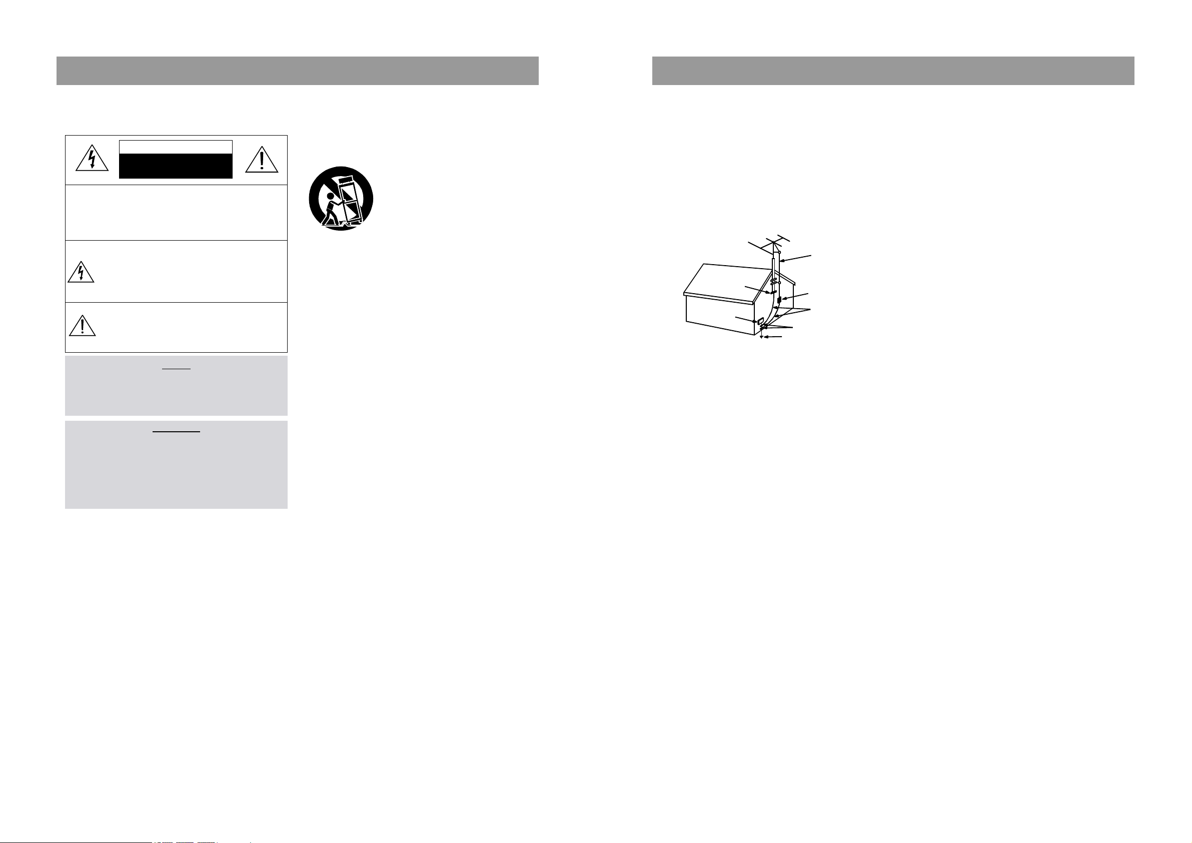
2. Carts and Stands - The appliance
should be used only with a cart or
stand that is recommended by th
manufacturer.
3. An appliance and cart combination
should be moved with care. Quick
stops, excessive force, and uneven
surfaces may cause the appliance
and cart combination to overturn.
4. Wall or Ceiling Mounting - The appli-
ance should be mounted to a wall or
ceiling only as recommended by the manufacturer.
5. Ventilation - The appliance should be situated so that its
location or position does not interfere with its proper
ventilation. For example, the appliance should not be situated
on a bed, sofa, rug, or similar surface that may block the
ventilation openings; or, placed in a built-in installation, such
as a bookcase or cabinet that may impede the flow of air
through the ventilation openings.
6. Heat - The appliance should be situated away from heat
sources such as radiators, heat registers, stoves, or other
appliances (including amplifiers) that produce heat.
7. Power Sources - The appliance should be connected to a
power supply only of the type described in the operating
instructions or as marked on the appliance.
8. Grounding or Polarization - The precautions that should be
taken so that the grounding or polarization means of an
appliance is not defeated.
9. Power - Cord Protection - Power-supply cords should be
routed so that they are not likely to be walked on or pinched
by items placed upon or against them, paying particular
attention to cords at plugs, convenience receptacles, and the
point where they exit from the appliance.
10.Protective Attachment Plug - If the appliance is equipped with
an attachment plug having overload protection. This is a
safety feature. See Instruction Manual for replacement or
resetting of protective device. If replacement of the plug is
required, be sure the service technician has used a
replacement plug specified by the manufacturer that has the
same overload protection as the original plug.
11.Cleaning - The appliance should be cleaned only as
recommended by the manufacturer.
12.Power Lines - An outdoor antenna should be located away
from power lines.
CAUTION
RISK OF ELECTRIC SHOCKS
DO NOT OPEN
PORTABLE CART
Figure 2
13.Outdoor Antenna Grounding - If an outside antenna is
connected to the receiver be sure the antenna system is
grounded so as to provide some protection against voltage
surges and built-up static charges. Article 810 of the National
Electrical Code, ANSI/NFPA 70, provides information with
regard to proper grounding of the mast and supporting
structure, grounding of the lead-in wire to an antenna-dis
charge unit, size of grounding conductors,location of antennadischarge unit, connection to grounding electrodes and
requirements for the grounding electrode. See Figure 1.
14.Non-use Periods - The power cord of the appliance should be
unplugged from the outlet when left unused for a long period
of time.
15.Object and Liquid Entry - Care should be taken so that objects
do not fall and liquids are not spilled into the enclosure through
openings.
16.Damage Requiring Service - The appliance should be
serviced by qualified service personnel when:
a) The power-supply cord or the plug has been damaged; or
b) Objects have fallen, or liquid has been spilled into the
appliance; or
c) The appliance has been exposed to rain; or
d) The appliance does not appear to operate normally or
exhibits a marked change in performance; or
e) The appliance has been dropped, or the enclosure
damaged.
17.Servicing - The user should not attempt to service the
appliance beyond that described in the operating instructions.
All other servicing should be referred to qualified service
personnel.
ANTENNA DISCHARGE UNIT
(NEC SECTION 810-20)
ANTENNA LEAD
IN WIRE
POWER SERVICE GROUNDING
ELECTRODE SYSTEM
(NEC ART 250 PART H)
GROUND CLAMP
ELECTRIC
SERVICE
EQUIPMENT
GROUNDING CONDUCTORS
(NEC SECTION 810-21)
GROUND CLAMPS
EXAMPLE OF ANTENNA
GROUNDING
NEC - NATIONAL ELECTRICAL CODE
Adjustments
4
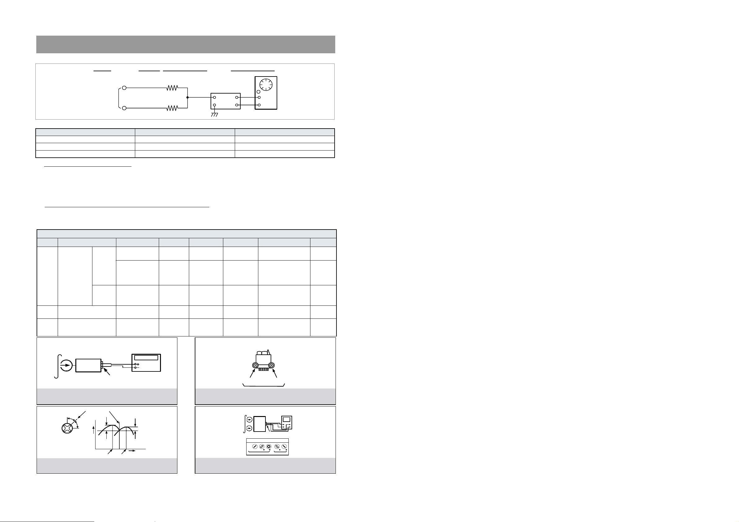
1. TAPE SECTION
Test Tape be used
HEAD ADJUSTMENT (AZIMUTH)
1. 10KHz test tape(example: MTT-114N) must be used for this adjustment.
2. Connect to VTVM or oscilloscope to the headphone jack or speaker terminal.
3. Press the play button.
4. Adjust the azimuth by using a screw driver to maintain the max. L&R output voltage.
5. Adjust tape A(1), tape B(2) respectively, Please secure the azimuth position by using locking paint.
RECORDING BIAS OSCILLATOR FREQUENCY ADJUSTMENT
1. Connect the frequency counter to TP603, GND.
2. Press the REC button.
3. Adjust L600 to obtain 80 KHz
±
500Hz
Tape Contents Use
MTT-111N 3 KHz Tape Speed Adjustment
MTT-114N 10 KHz Head Azimuth Adjustment
MTT-5511 Blank Record Frequency Property
VTVM
Scope
R-CH
L-CH
47 kohm
47 kohm
Input Level
Measurement
Point
Input Point
Output Level
Measurement
Point
TAPE ALIGNMENT CHART
Step Item Reference Value Test Tape Adjust Point Test Point Note FIG.
1
Tape Speed
Adjustment
Normal
3,015~3,025Hz MTT-111N RV600
Line Out L/R
Channel
Line Out L/R
Channel
Confirm Wow & Flutter is within 0.35%
FIG.1
3,000~3,010Hz MTT-111N RV600
Line Out L/R
Channel
Confirm Tape Speed
of end position after
adjustment at tape
start position
FIG.1
High
5,820~6,180Hz MTT-111N - - - - - -
Confirm High speed
after normal speed
adjustment
FIG.1
2
Azimuth Adjustment
Maximum Level
Phase:Within90∞
MTT-114N Head Screw
Line Out L/R
Channel
FIG.2,3,4
3
Recording Bias Oscillator Frequency Adjust-
ment
80 KHz
±
0.5
MTT-5511 L600
TP603,GND
Adjust with frequency
counter connected.
FIG.1
FIG. 1 : Tape Speed & Record Bias Oscillator
Frequency Adjust Circuit
Test Tape : MTT-111N(3kHz)
MTT-5511(Blank)
Frequency Counter
Output Level
Measurement Point
Set
FIG. 2 : Tape Azimuth Adjust Location
(Record/Playback Head)
FIG. 3 : Tape Azimuth Adjust Head Screw & Waveform
FIG. 4 : Tape Azimuth Adjust Circuit & Waveform
Forward
Side
Reverse
Side
Adjust with Frequency
Counter Connected
L-CH
Peak
R-CH
Peak
Screw
Angle
Output Level
within
1 dB
within
1 dB
L-CH
Peak
R-CH
Peak
Screw Angle
VH
Oscilloscope
L-CH
Output Level
Measurement Point
Set
Test Tape
MTT-114N
(10kHz)
Screen Pattern
In Phase 45 90 135 180
Good Wron g
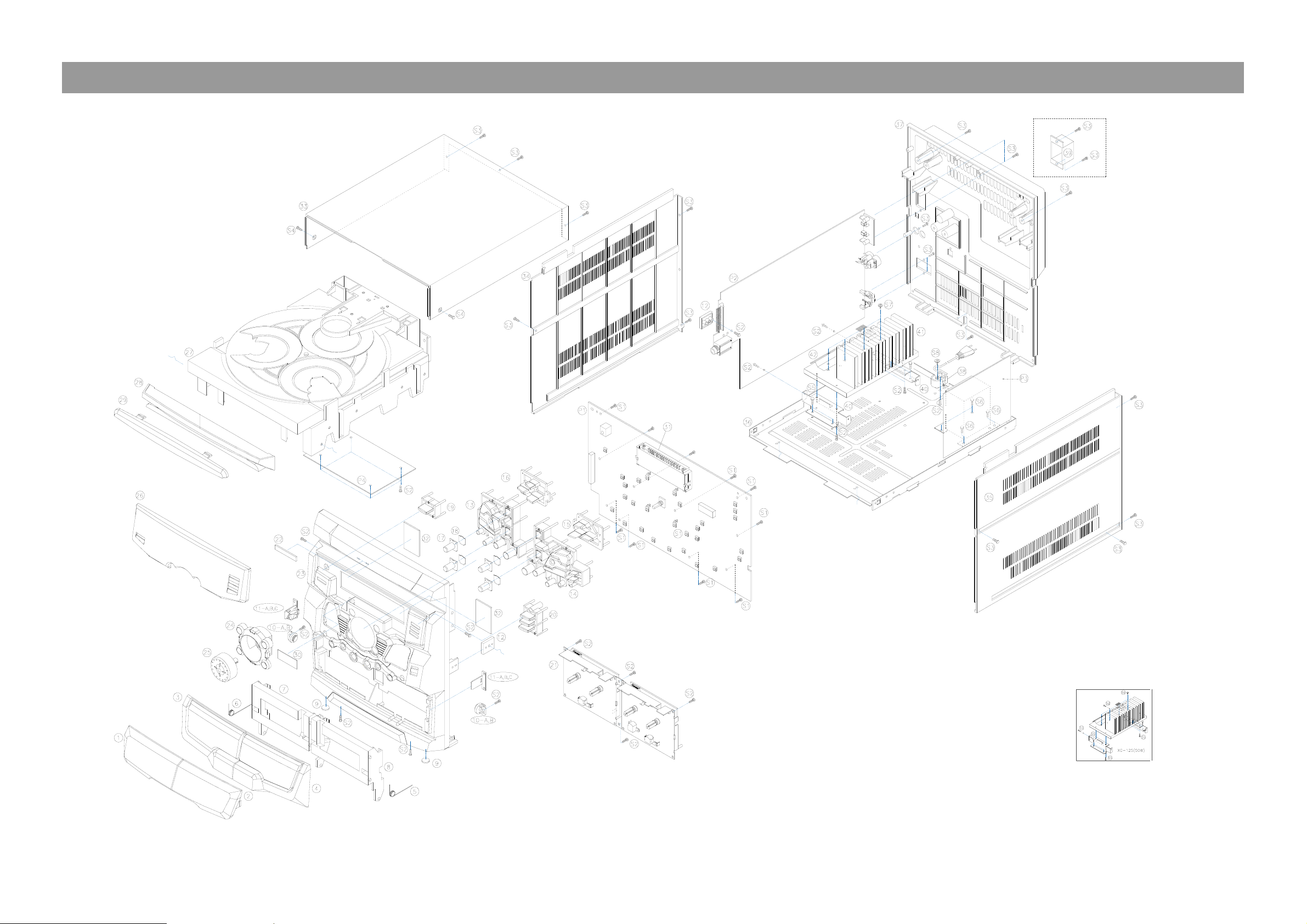
Exploded View and Mechanical Parts List
5
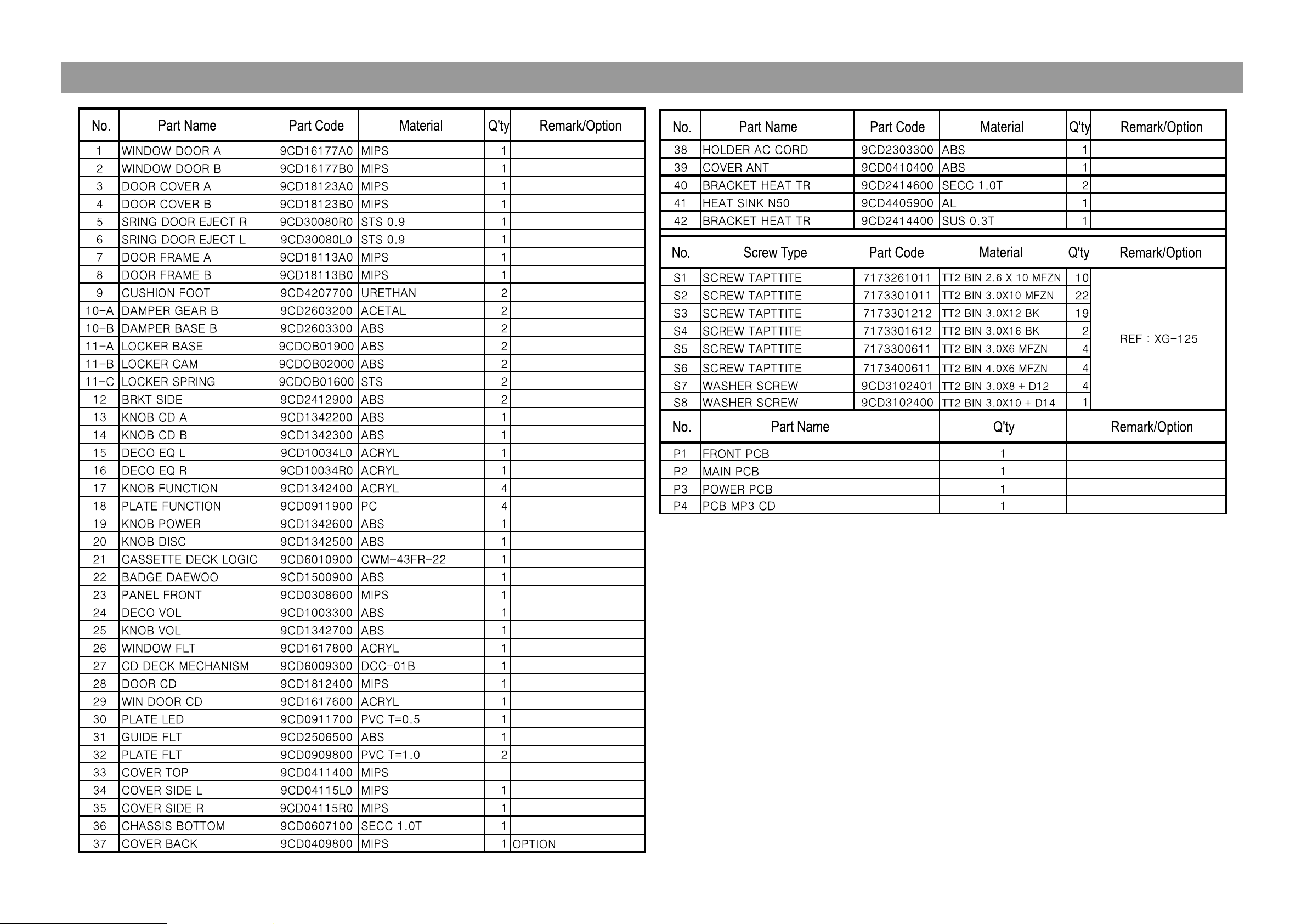
Exploded View and Mechanical Parts List
6
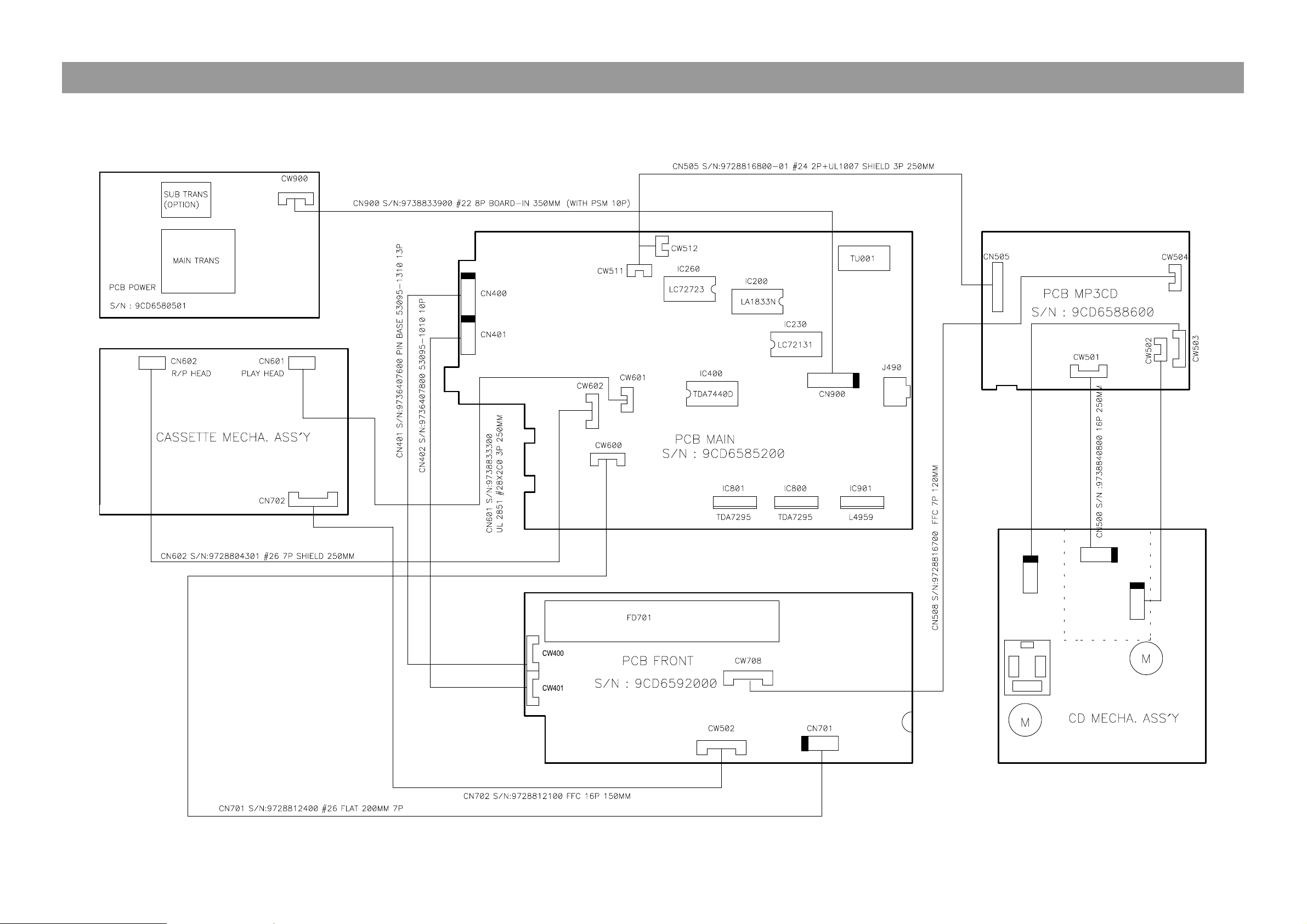
Wiring Diagram
7
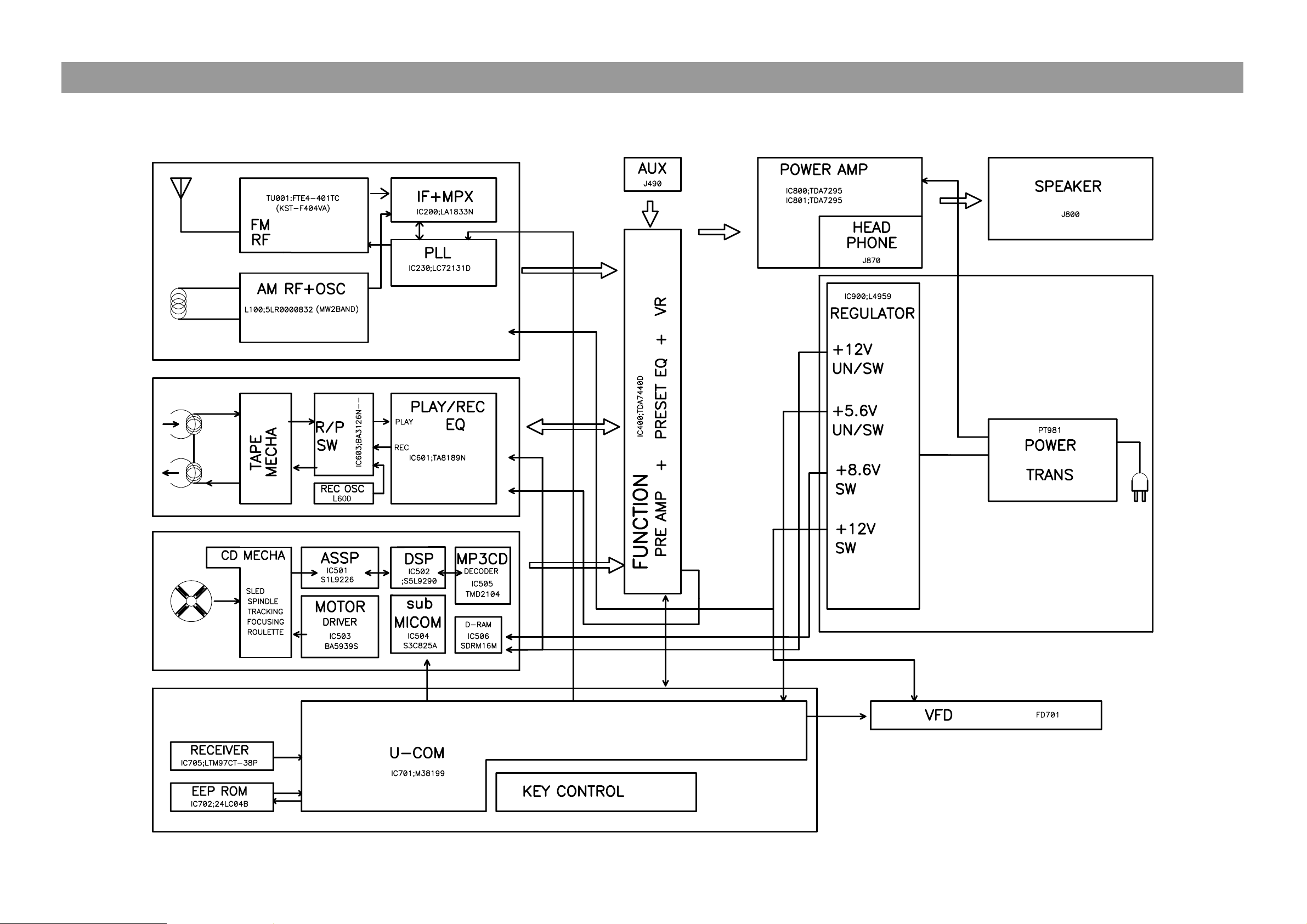
Block Diagram
8
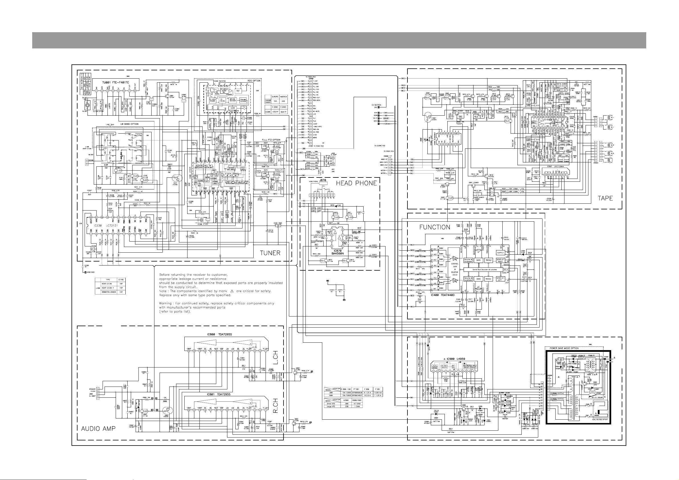
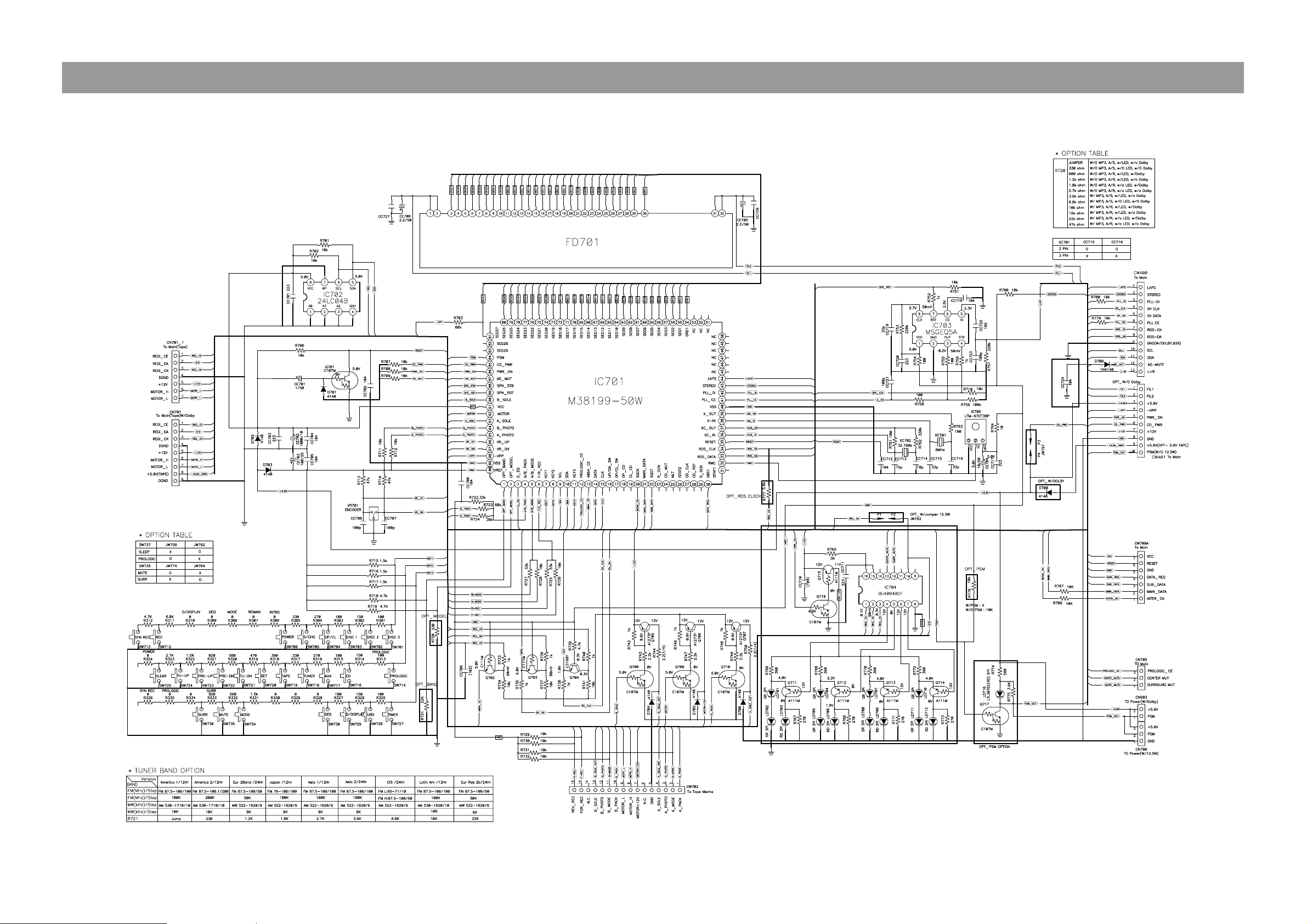
Schematic Diagram
"
TUNER / TAPE / AMP / POWER
9
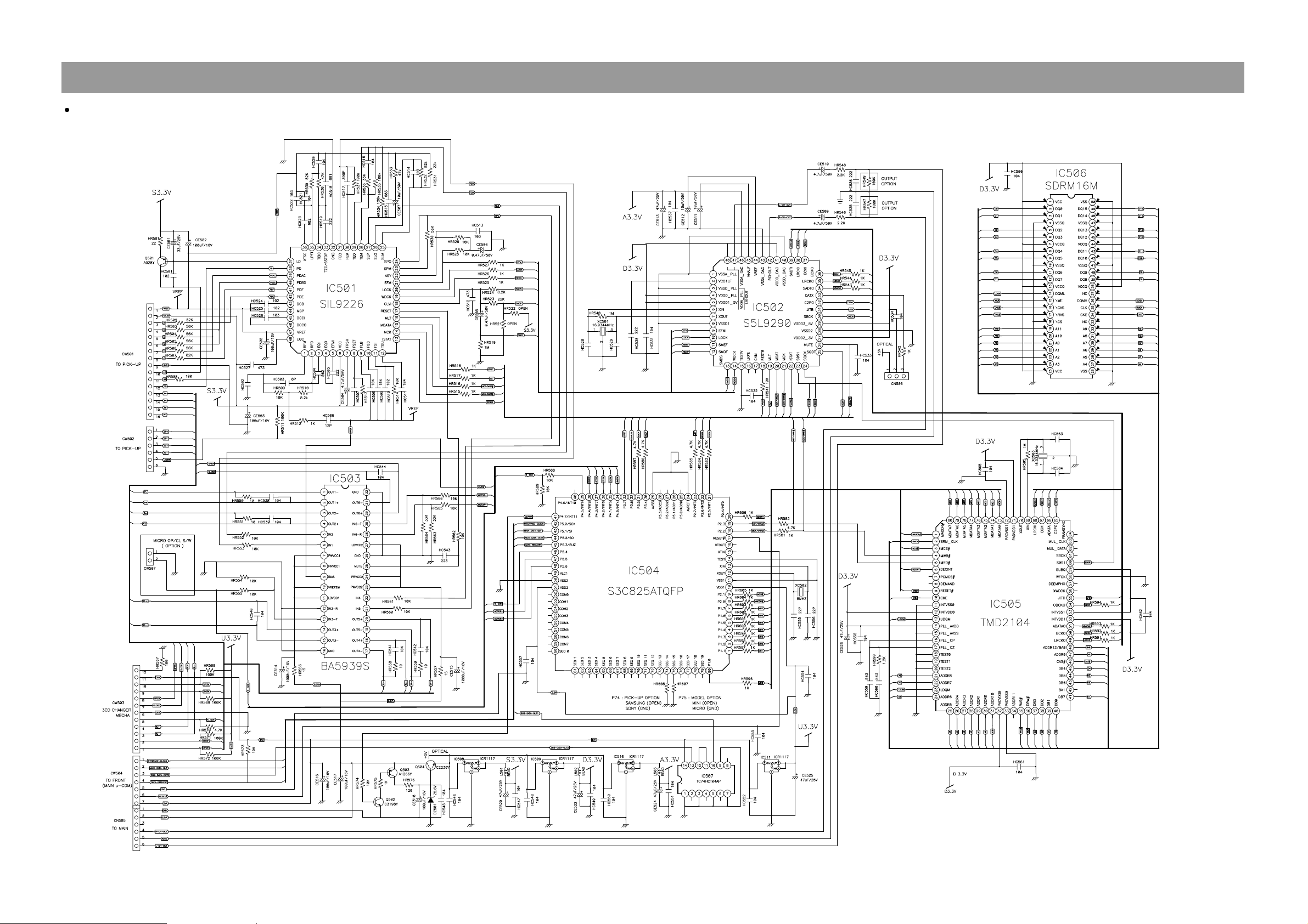
MP3 CD
10
Schematic Diagram
Schematic Diagram
"
FRONT
11
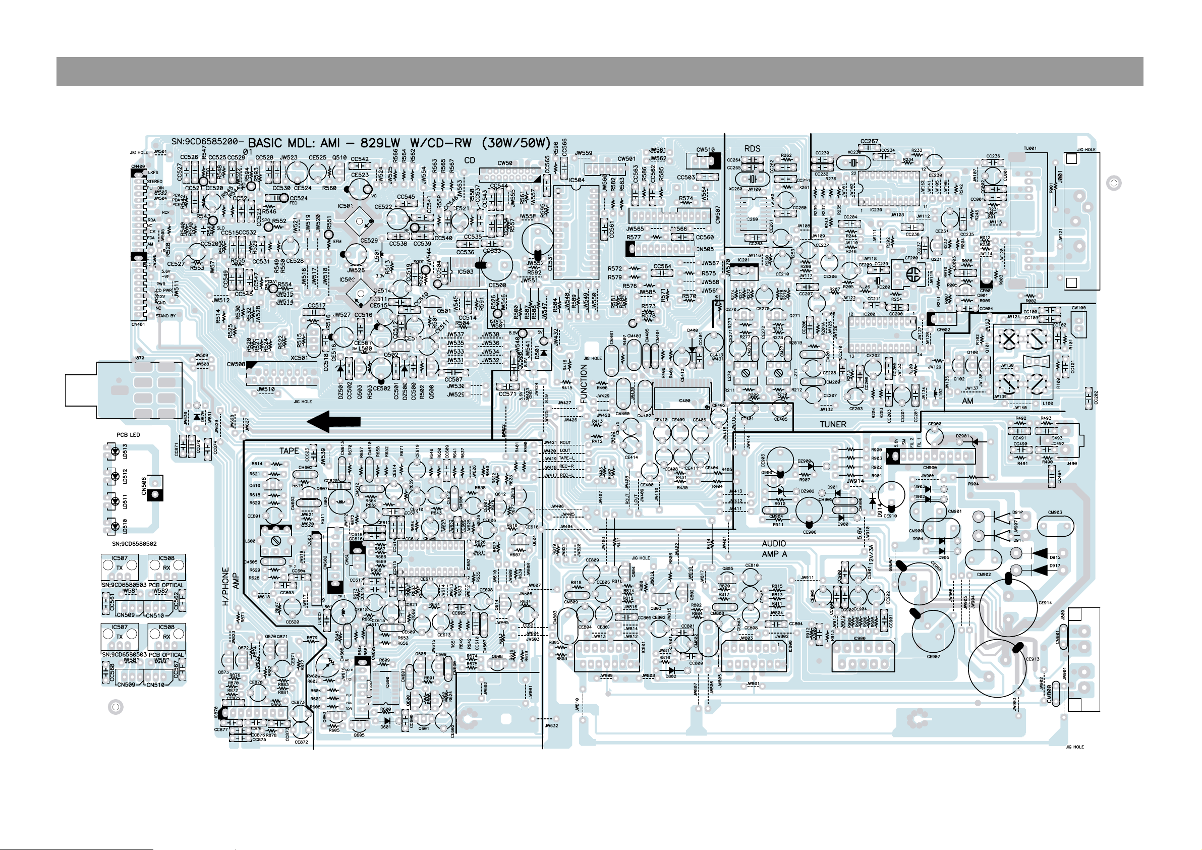
P.C.B Pattern Layout
"
Main
12
 Loading...