

Page 1

S/M No. : TMECHA
Service Manual
VCR MECHANISM UNIT
(T-MECHA DECK)
DAEWOO ELECTRONICS CO., LTD.
http : //svc.dwe .co.kr
Feb. 2000
Page 2

1
CONTENTS
1. ASSEMBL Y DIAGRAM AND A/S............................................................................................2
2. WIRE DIAGRAM........................................................................................................................5
3. PERIODIC MAINTENANCE AND SERVICE SCHEDULE....................................................6
4. SERVICE SCHEDULE FOR THE MAJOR P ARTS................................................................7
5. JIGS AND TOOLS.....................................................................................................................8
6. DEASSEMBL Y AND REPLACEMENT.................................................................................10
7. MECHANICAL ADJUSTMENT..............................................................................................16
8.ADJUSTMENT OF THE T APE TRANSPORTING SECTION..............................................19
9. EXPLODED VIEW AND P ARTLIST.......................................................................................25
Page 3
22
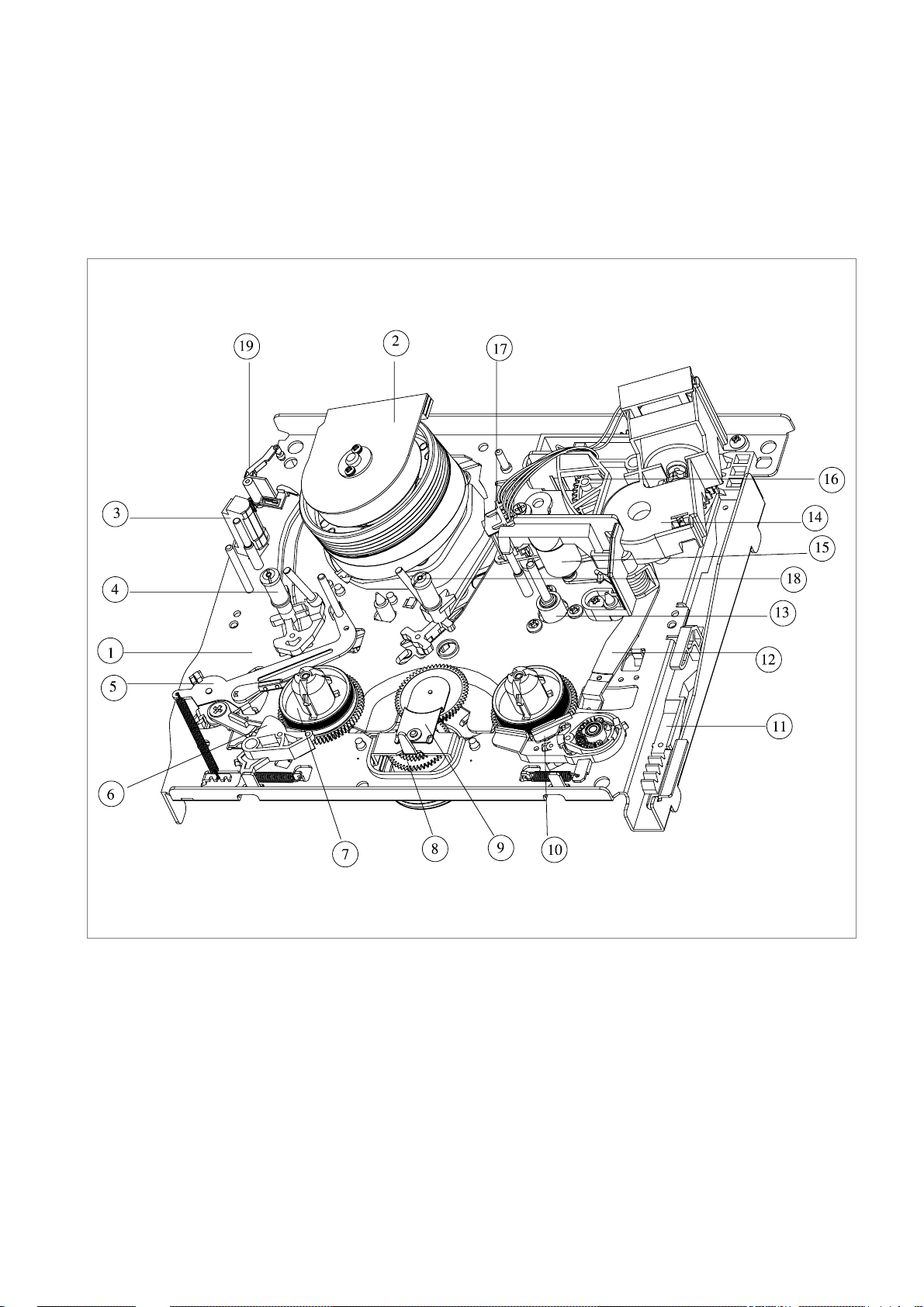
1. Assembly diagram
1-1. DECK Assembly diagram
A. Upper View
ASSEMBLY DIAGRAM AND A/S
1 MAINBASE ASS’Y
2 DRUM ASS’Y
3 FE HEAD
4 S SLANT POLE ASS’Y
5 TENSION BAND ASS’Y
6 S BRAKE ASS’Y
7 S REEL TABLE
8 REEL BRKT TOTAL ASS’Y
9 IDLER PLATE TOTAL ASS’Y
10 T BRAKE ASS’Y
11 FL RACK
12 RELAY LEVER
13 CAPSTAN MOTOR
14 LC BRKT ASS’Y
15 PINCH LEVER TOTAL ASS’Y
16 CAM GEAR
17 AC HEAD ASS’Y
18 T SLANT POLE ASS’Y
19 HEAD CLEANER
fig1-1
Page 4
3
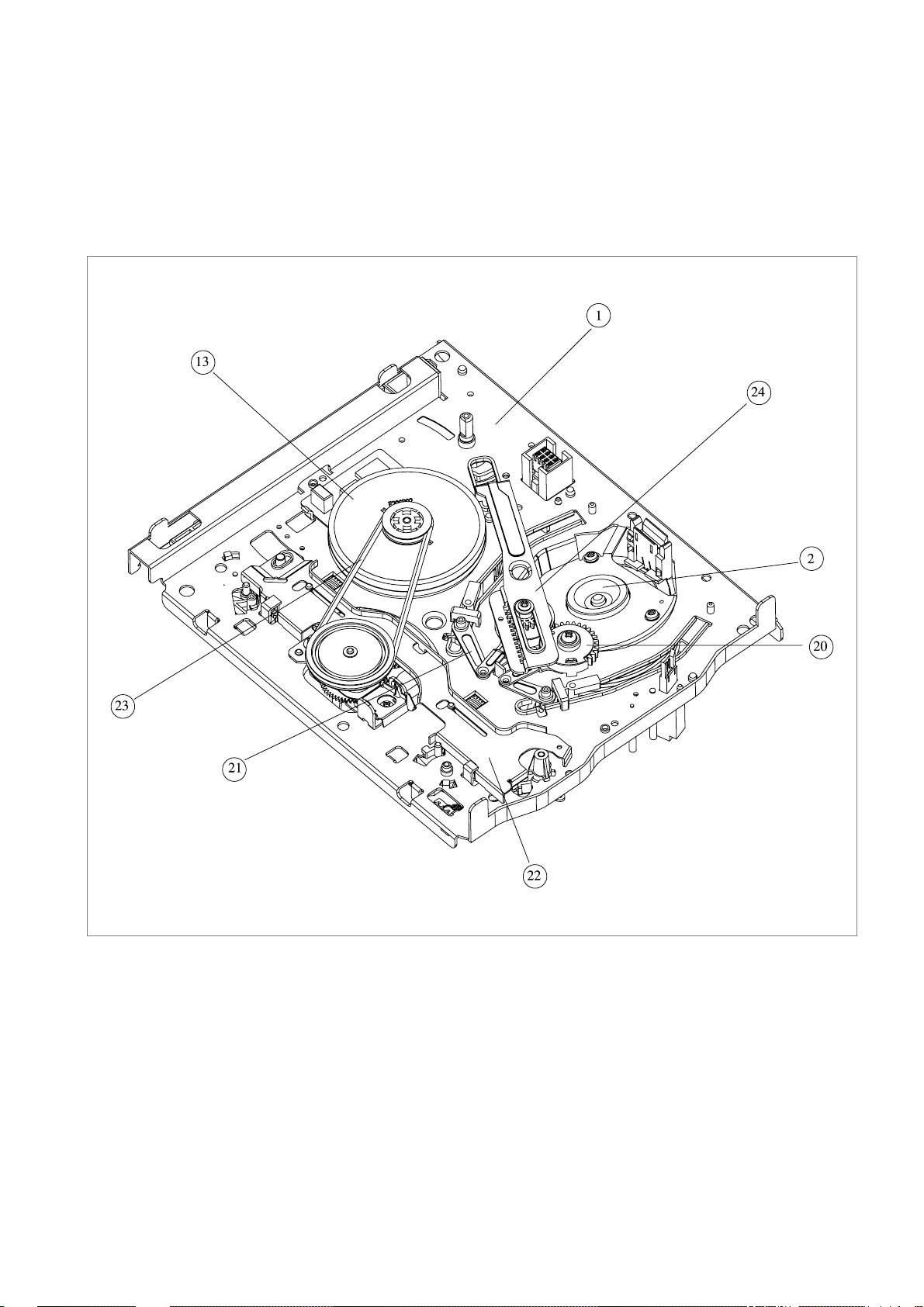
ASSEMBLY DIAGRAM AND A/S (CONTINUED)
B. Lower V iew
20 L LOADING ASS’Y
21 R LOADING ASS’Y
22 CONNECT PLATE
23 REEL BELT
24 LOADING RACK
fig1-2
Page 5
4
ASSEMBLY DIAGRAM AND A/S (CONTINUED)
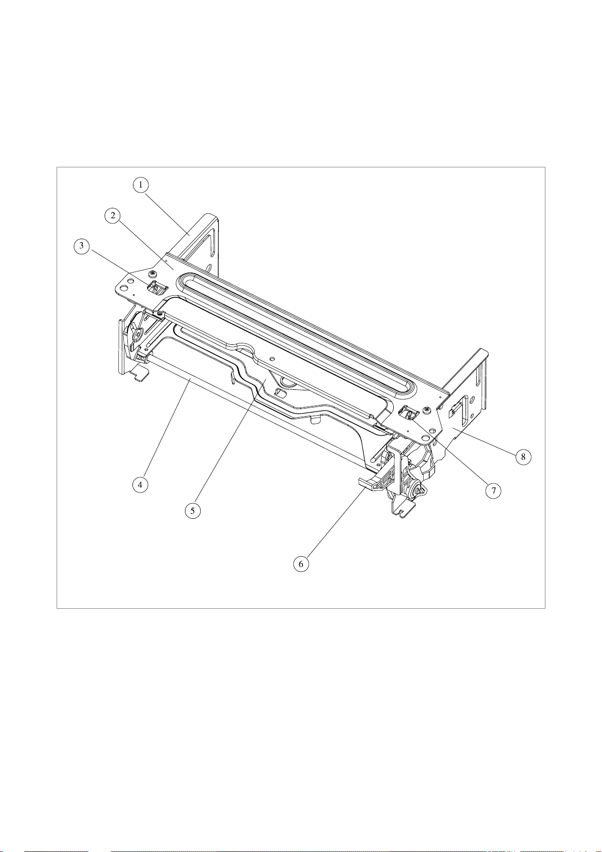
1-2. FRONT LOADING Assembly diagram
1 FL BRKT L
2 TOP PLATE
3 SAFETY LEVER
4 LOADING LEVER AS4
5 CST HOLDER AS
6 DOOR OPENER
7 SAFETY LEVER R
8 FL BRKT R
fig2
Page 6
5
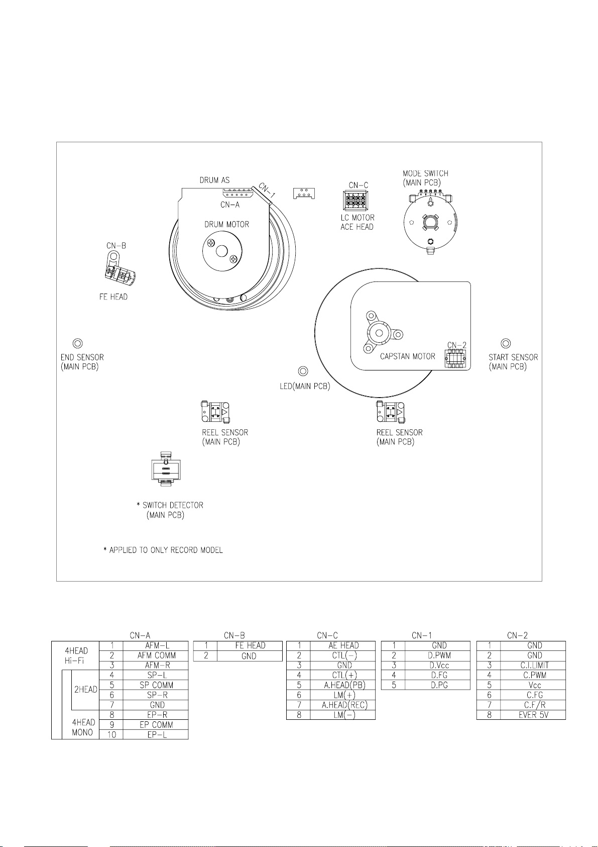
2. Connector Pin Arrangement
1. Wire Diagram
WIRE DIAGRAM
Page 7

6
1. PERIODIC MAINTENANCE AND SERVICE
SCHEDULE
A. In order to effectively maintain the excellent performance
and fully utilize the features of this apparatus, and to lengthen
the life of the mechanism and tapes, we strongly urge you to
perform periodic maintenance and inspection, as described
below.
* After repairing, do the maintenance described below, irrespec-
tive of the length of time in use.
B. Cleaning of the Head Drum Ass'y
- Clean the Drum assembly with a cleaning cloth soaked in
liquid cleaner (alcohol) by placing lightly against the
Drum and slowly revolving the rotating HEAD DRUM
Ass'y by hand (Do not rotate the upper Drum by applying
electric power to the motor when cleaning).
- Do not move the cleaning cloth in the vertical direction
against the heat-tip.
C. Cleaning the tape transporting section.
- Clean the tape transporting parts with a cleaning cloth
soaked in alcohol.
D. Cleaning of driving section
- Clean the driving section with a cloth soaked in alcohol.
E. Routine inspection
- Perform maintenance and inspection as separately
described depending on the period of time in use.
- Refer to the table of 2-2-3.
2. CLEANING AND LUBRICA TION
A. Cleaning of Tape Transporting section and Driving section
a. Cleaning of Tape Transporting section
- The following parts should be cleaned after every 500 hours
of use.
• TENSION POLE • S SLANT POLE
• AC HEAD/AE HEAD • S GUIDE POST
• VIDEO HEAD/DRUM • T GUIDE POST
• FE HEAD • T SLANT POLE
• CAPSTAN SHAFT • S GUIDE ROLLER
• T GUIDE ROLLER • PINCH ROLLER
• VERTICAL POST
- As the above parts contact with the video tape, they tend to
collect dust particles. If they are stained with dust or foreign
substance it has a bad effect on the picture and may lead to
damage of the tape.
- After cleaning with alcohol, allow the parts to dry thoroughly
before using a cassette tape.
b. Cleaning of Driving section
• REEL TABLE
• CAPSTAN FLYWHEEL/PULLEY
• REEL PULLEY
B. LUBRICATION
• S REEL POST
• T REEL TABLE POST
• REEL GEAR POST
- After cleaning these parts with alcohol, lubricate these with
one or two drops of oil.
PERIODIC MAINTENANCE AND SERVICE SCHEDULE
Page 8

7
SERVICE SCHEDULE FOR THE MAJOR PARTS
SERVICE SCHEDULE FOR THE MAJOR PARTS
The following parts should receive periodic service, according to the recommended intervals.
: Check and Replace if necessary. : Replace
PERIODIC SER VICE (TIME)
NAME
1000 2000 3000 4000 5000
DRUM TOT AL ASS'Y
CAPST AN MOTOR
L/C BRKT TOT AL ASS'Y
REEL BEL T
IDLER PLATE TOTAL ASS'Y
REEL T ABLE
TENSION BAND ASS'Y
S, T BRAKE ASS'Y
PINCH ROLLER ASS'Y
AC HEAD ASS'Y
FE HEAD
REEL GEAR TOT AL ASS'Y
Note: Even though the unit is not used frequently, cleaning, lubrication and replacement of the belt should be undertaken every 2 years.
Page 9

8
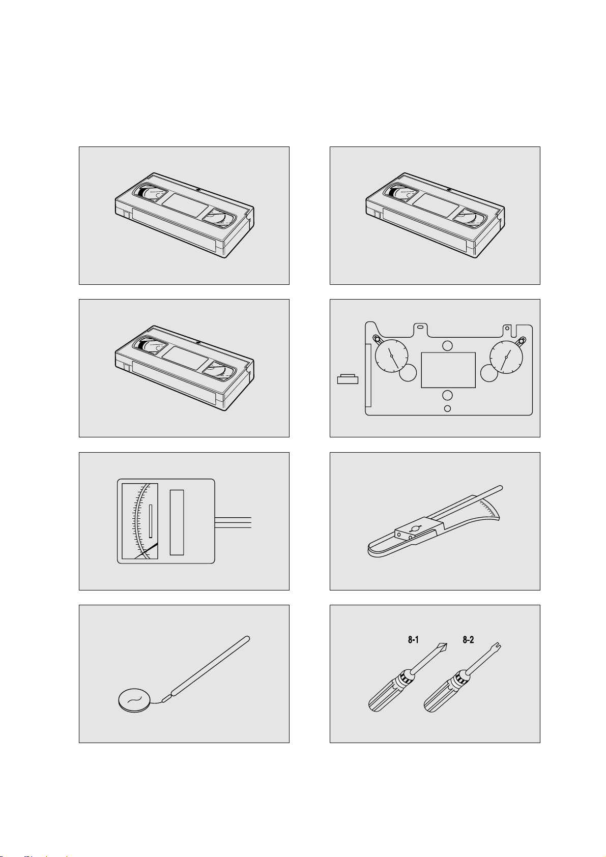
JIGS AND TOOLS
1. List of Jigs and Tools
FIG.
NO ITEMS MODEL
N O
REMARKS
NTSC: SP MONOSCOPE 7KHz CHECKING OF THE
1 ALIGNMENT TAPE SP COLORBAR 1KHz ! T APE TRANSPOR TING
(EP MONOSCOPE) SYSTEM
P AL/SCAM: SP MONOSCOPE 6KHz
SP COLORBAR 1KHz
(LP MONOSCOPE)
2
CLEANING T APE
DHC-602V @
CHECKING OF THE T APE
(DAEWOO) TRANSPORTING SYSTEM
3
CASSETTE T APE KT -300NV
#
MEASUREMENT OF
(KOKUSAI) KT -300RV REEL TORQUE
4
VHS SPINDLE
TSH-V4 $
MEASUREMENT OF
HEIGHT GAUGE REEL HEIGHT
5
TENTELO METER
T2-H7-UM %
MEASUREMENT OF
(TENTELO) THE BACK TENSION
F AN TYPE MEASUREMENT OF THE
6 TENSION METER BELOW 3KG ^ PRESSING FORCE FOR
THE PINCH ROLLER
7 DENTAL MIRROR &
CHECKING OF THE T APE
TRANSPORTING SYSTEM
8
+DRIVER *-1 ASSEMBLY,
DISASSEMBLY
ADJUSTMENT DR IVER *-2 AND ADJUSTMENT
Page 10
9
JIGS AND TOOLS(CONTINUED)
2. Sketch of Jigs and Tools
!
#
%
&
@
$
^
*
ALIGNMENT TAPE
CLEANING TAPE
30
20
10
30
0
20
10
VHS SPINDLE
HEIGHT GAUGE
30
20
10
30
0
10
20
Page 11
10
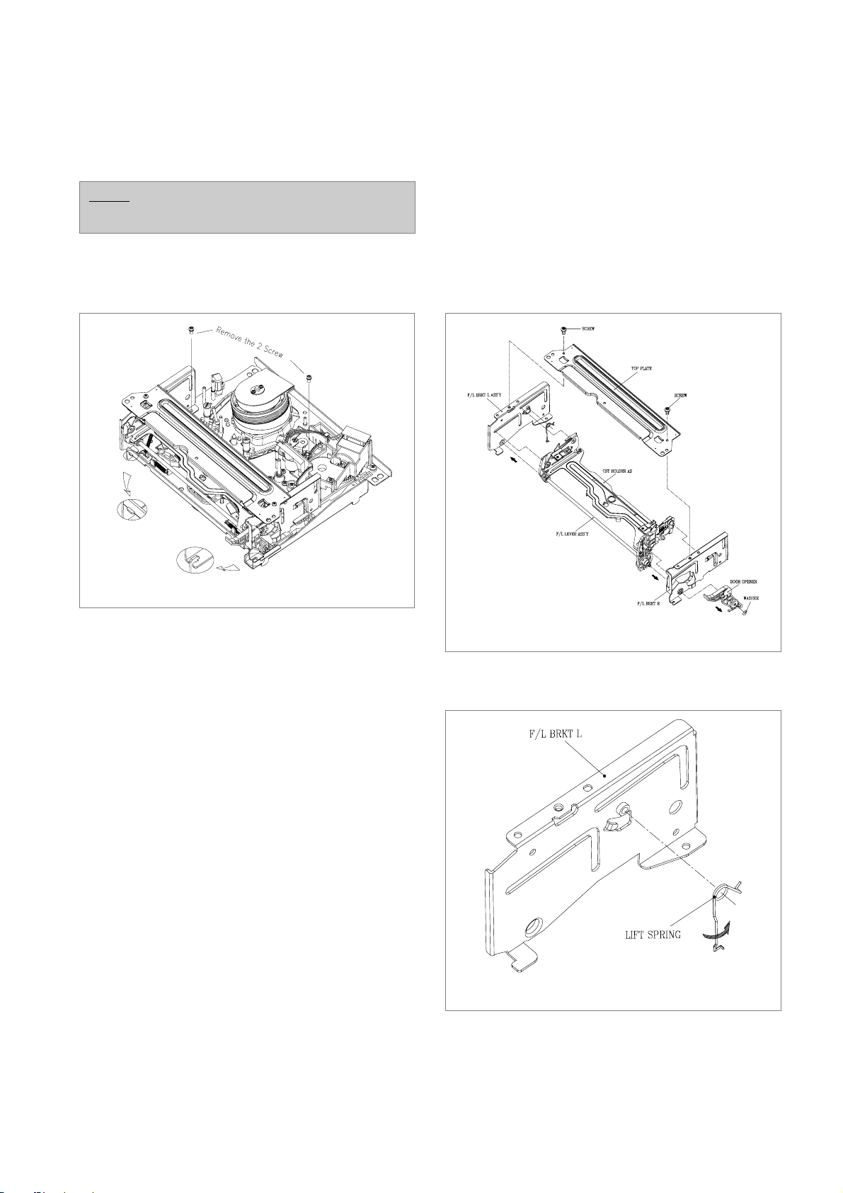
1. Removal of the FRONT LOADING Ass’y
(Fig. 3.1)
a. Unscrew the 2 screw holding the F/L.
b. Separate the F/L Ass’y from the MAINBASE settling
down point by lifting the rear part of F/L (Screw Hole).
2. Deassembly of FRONT LOADING Ass’y
(FIg. 3.2~3.5)
a. Remove the 1 washer for holding the door opener and
separate F/L Assembly by moving the DOOR OPENER
in the direction of arrow.
b. Remove the 2 screw holding the TOP PLATE and sepa-
rate the CASSETTE HOLDER Ass’y by moving the FL
BRKT L and FL BRKT R in the direction of arrow. (Fig.
3.2)
c. Separate the FL LIFT SPRING by twisting and dragging
from FL BRKT R. (Fig. 3.3)
DEASSEMBLY AND REPLACEMENT
NOTE:
Remove the FRONT LOADING Ass’y in eject mode.
Fig. 3.1 Removal of the FRONT LOADING Ass’y
FIg. 3.2 Deassembly of the FRONT LOADING Ass’y
FIg. 3.3 Deassembly of the FL BRKT Ass’y
Page 12

11
d. Separate the LOADING LEVER Ass’y by pressing the
connection point from the CASSETTE HOLDER Ass’y.
(Fig. 3.4)
e. Remove the SAFETY SPRING connecting the SAFETY
LEVER and CASSTTE HOLDER PLATE. (Fig. 3.4)
f. Remove the RELEASE SPRING connecting the
RELEASE LEVER and SAFETY LEVER. (Fig. 3.4)
3. Deassembly of DRUM Ass’y (Fig. 3.6)
a. Turn over the DECK MECHANISM and holding the
DRUM TOTAL Ass’y @ with hands, remove the 3
screw holding the drum total assembly with mainbase.
b. Separate the DRUM TOTAL Ass’y from the deck paying
attention there is no damage on the surface of VIDEO
HEAD and DRUM.
c. Assembly step is the reverse way of deassembly.
DEASSEMBLY AND REPLACEMENT (CONTINUED)
CAUTION:
• Assemble the FRONT LOADING Ass’y in the reverse
step of deassembly.
• Confirm that 2 bosses on the left side of the CASSETTE
HOLDER Ass’y are inserted in the groove on the left
side of the top plate. Insert 2 bosses on the right side of
the CASSETTE HOLDER Ass’y into the groove of the
F/L BRACKET R. (Fig. 3.5)
FIg. 3.4 Deassembly of the CASSETTE HOLDER Ass’y
FIg. 3.5 Assembly of the FL Ass’y
CAUTION:
• After the assembly of the DRUM TOTAL Ass’y, check
out if DECK Mechanism operate smoothly and adjustment of tape transmission section is OK.
FIg. 3.6 Assembly of the DRUM TOTAL Ass’y
Page 13

12
4. Deassembly of LOADING RACK, LOADING
ASS’Y, S/T SLANT POLE ASS’Y (Fig. 3.7, 3.8)
a. Turn out the DECK MECHANISM and remove the
LOADING RACK@ after unscrewing the SCREW !.
b. Disintegrate the R LOADING AS # and L LOADING
AS $.
c. Disintegrate the S SLANT POLE AS % and T SLANT
POLE AS ^ by moving those part in arrow direction.
5. Deassembly of the A/C HEAD ASS’Y (Fig. 3.9)
a. Remove the CONNECTOR @ from the AC HEAD
Ass’y, watch out that there is no damage in the HEAD
connecting PIN.
b. Separate the AC HEAD Ass’y ! after unscrewing the
screw #.
DEASSEMBLY AND REPLACEMENT (CONTINUED)
CAUTION:
• Take care GUIDE ROLLER of S/T SLANT POLE AS
and SLANT POLE not to be stained with grease during
assembly.
• Refer to Fig. 3.8 in assembly.
FIg. 3.7 Deassembly of the LOADING RACK, LOADING
ASS’Y and the SLANT POLE ASS’Y
FIg. 3.8 Assembly of the L/R LOADING AS and the
LOADING RACK
CAUTION:
• After the assembly, adjust the tape transmission section
by refering to the chapter 5.
• After the adjustment of the tape transmission section,
paint the 3 adjustment screw with locking paint.
FIg. 3.9 Deassembly of the AC HEAD ASS’Y
Page 14

13
6. Deassembly of the LC BRKT ASS’Y, PINCH
LEVER TOTAL ASS’Y (Fig. 3.10)
a. Separate the LC BRKT Ass’y @ after removing the 3
screw !.
b. Separate the LC BRKT Ass’y @ from the DECK
MECHANISM.
c. Disintegrate the PINCH LEVER TOTAL Ass’y #.
7. Deassembly of the CAM GEAR, RELAY LEVER,
FL RACK (Fig. 3.10)
a. Separate the CAM GEAR % from the MAINBASE.
b. Separate the RELAY LEVER ^ from the MAINBASE.
c. Separate the FL RACK & from MAINBASE by moving
to the arrow direction.
DEASSEMBLY AND REPLACEMENT (CONTINUED)
CAUTION:
• After the assembly of the PINCH LEVER TOTAL
Ass’y, adjust the tape transmission section by refering to
the chapter 5.
• There should be no pollution on the surface of PINCH
ROLLER $ with grease or other foreign material.
• Make sure if the end of the PINCH SPRING PINCH
“A” is located at the end of trajectory of CAM GEAR
“B” in assembly. (Refer to Fig. 4.3)
CAUTION:
• When reassembling, refer to Fig. 3.11, Fig. 3.12 and
chapter 4.
FIg. 3.10 Deassembly of the LC BRACKET ASS’Y from
the PINCH LEVER TOTAL ASS’Y
FIg. 3.11 Assembly of the CAM GEAR, RELAY LEVER
FIg. 3.12 Assembly of the CAM GEAR, FL RACK
Page 15

14
8. Deassembly of the S/T BRAKE ASS’Y (Fig. 3.13)
a. Unhook the S BRAKE SPRING # from the MAIN-
BASE HOOK !.
b. Remove the S BRAKE Ass’y @ from the mainbase.
c. Remove the T BRAKE SPRING ^ from the MAIN-
BASE HOOK $.
d. Remove the T BRAKE Ass’y %.
9. Deassembly of the TENSION BAND ASS’Y
(Fig. 3.14)
a. Unhook the TENSION SPRING @ from the MAIN-
BASE HOOK !.
b. Unhook the MAINBASE HOOK “A” and remove the
TENSION BAND Ass’y # from the mainbase.
10.Deassembly of the Capstan Motor (Fig. 3.14)
a. Separate the CAPSTAN MOTOR % after the removal of
3 screw $ holding the capstan motor.
11. Deassembly of the FE HEAD (Fig. 3.14)
a. Unscrew the screw ^ and separate the FE HEAD &
from the MAINBASE.
DEASSEMBLY AND REPLACEMENT (CONTINUED)
CAUTION:
• After the assembly of TENSION BAND Ass’y on the
mainbase, adjust the TENSION POLE location as
shown in Fig. 3.15.
• Avoid getting Grease, Oil or Foreign substance on the
FELT of the BAND BRAKE.
• Take care not to deform the MAINBASE HOOK “A”
when separating the TENSION BAND Ass’y #.
FIg. 3.13 Deassembly of the S/T BRAKE ASS’Y
FIg. 3.14 Deassembly of the TENSION BAND ASS’Y,
CAPSTAN MOTOR and the FE HEAD
FIg. 3.15 Adjustment of the TENSION POLE POSITION
Page 16

15
12. Deassembly of the REEL T ABLE, IDLER
PLA TE T OTAL ASS’Y (Fig. 3.16)
a. Remove the POLY WASHER ! and separate the
IDLER PLATE TOTAL Ass’y @ from the mainbase.
b. Remove the REEL TABLE $ from the REEL TABLE
POST # of the MAINBASE.
13. Deassembly of the REEL BRKT TOT AL ASS’Y,
CONNECT PLA TE (Fig. 3.17)
a. Turn over the DECK MECHANISM and remove the 2
screw !.
b. Remove the REEL BRKT TOTAL Ass’y @ from the
MAINBASE.
c. Separate the CONNECT PLATE # from the MAIN-
BASE by pushing to the direction of the arrow.
DEASSEMBLY AND REPLACEMENT (CONTINUED)
CAUTION:
• Take care not to deform the IDLER PLATE TOTAL
Ass’y @ when assembling and deassembling.
CAUTION:
• In deassembly of the REEL BRKT TOTAL Ass’y, take
care REEL BELT and REEL FELT not to be stained
with Grease, Oil or Foreign substance.
• Deassembly of the IDLER Ass’y should be precede the
deassembly of the REEL BRKT TOTAL Ass’y.
• Check the operation of the REEL BRKT TOTAL Ass’y
before assembly.
• Check the operation of FF/REW, PLAY, CUE and
REVIEW work well and existence of noise during the
mode operation.
FIg. 3.16 Deassembly of the REEL TABLE and the IDLER
PLATE TOTAL ASS’Y
FIg. 3.17 Deassembly of the REEL BRKT TOTAL ASS’Y
and the CONNECT PLATE
Page 17

16
1. Mechanical Adjustment (Fig. 4.1~4.4)
In case of deassembly and reassembly for fixing the mechanical problem, check the following check point.
a. Make sure that the DATUM HOLE of the CAM GEAR is
aligned with the DATUM HOLE in the MAINBASE in
the EJECT mode as shown in Fig. 4.1.
b. Make sure that the ending part “A” of the RELAY
LEVER assembled on the CONNECT PLATE is aligned
with the reference hole “B” of the MAINBASE as shown
in Fig. 4.2.
c. The end point “A” of PINCH SPRINGPING of the
LEVER TOTAL Ass’y should be located within the trajectory “B” of the CAM GEAR. (Fig. 4.3)
MECHANICAL ADJUSTMENT
FIg. 4.1 Assembly reference between the FL RACK and the
CAM GEAR
FIg. 4.2 Assembly reference between the RELAY LEVER
and the CAM GEAR
FIg. 4.3 Assembly reference of the PINCH LEVER TOTAL
ASS’Ywith the CAM GEAR
Page 18

17
d. Make sure that the triangular mark “A” of the L LOAD-
ING Ass’y is aligned with the mark “b” of the R LOADING Ass’y. (Fig. 4.4)
e. Reference hole “C” of the LOADING RACK should be
aligned with the reference hole of the R LOADING Ass’y
to make the teeth of the LOADING RACK is aligned as
shown in Fig. 4.4.
2. Adjustment and measurement of the BACK
TENSION (Fig. 4.5, 4.6)
a. Check that the location of the TENSION POLE is in the
right position. If not, adjust that by refering to the “4.
Adjustment of the position of the TENSION POLE”.
b. Playback the T-120 Tape in S-MAX for 20 seconds.
(Generally tape transporting section is settled down in 20
seconds)
c. Measure the BACK TENSION by using the TENTELO
METER. (Refer to Fig. 4.5) The result should be within
the range of 20g~30g.
d. If the BACK TENSION is out of the range, change the
position of the TENSION SPRING of repeat the process
of “4. Adjustment of the position of the TENSION
POLE”. (Fig. 4.6)
MECHANICAL ADJUSTMENT (CONTINUED)
FIg. 4.4 Assembly reference between the LOADING RACK
and the LOADING LEVER ASS’Y
CAUTION:
• If the measurement result greater than the upper limit,
change the hook point of the spring to the “A”.
• Confirm that all of the three probes of TENSION meter
are in contact with the tape.
• During measuring, don’t touch any other parts of the
MECHANISM(i.e, MAINBASE). It is recommended
that this measurement be repeated at least three times for
an accurate reading.
FIg. 4.5 Measurement of the BACK TENSION
Page 19

18
3. Mechanical Mode (Operate without a cassette
tape)
a. Remove the FRONT LOADING Mechanism from the
DECK Mechanism.
b. Cap the IR LED and pull the FL RACK. This has the
same effect with cassette loading to the deck.
c. If the S/T POLE BASE is loaded, Play mode starts auto-
matically. If you want other function, press the corresponding button.
d. Turn off the poser when the Mechanism is in the desired
position.
4. Adjustment of the position of the TENSION
POLE (Fig. 4.6)
a. Place the Mechanical mode in the play mode. Refer to the
above section “3. Mechanical mode”.
b. Confirm that the TENSION LEVER is aligned with the
datum hole of the MAINBASE.
c. If the requirement “b” is not satisfied, turn the BAND
BRAKE ADJUST CAP clockwise or counterclockwise
until the two datum holes alignes with each other.
MECHANICAL ADJUSTMENT (CONTINUED)
FIg. 4.6 Adjustment of the TENSION POLE
Page 20

19
ADJUSTMENT OF THE TPAE TRANSPORTING SECTION.
Generally, tape transporting section has been precisely adjusted in the factory and does not require the ordinary readjustment.
But there is the case that tape noise or impact on the deck mechanise, tape transporting section readjustment is required, in
adjustment of the tape tranmission section consut the following flow chart.
If any components shown in Fig. 5.1, tape transporting section will be changed. To readjust the change of tape transporting section, keep in mind and follow the following check points.
FIg.5.1 A schematic diagram of the tape transporting section
Page 21

20
Generally the TAPE TRANSPORTING SYSTEM has been precisely adjusted in the factory and does not ordinarily require readjustment. But
when noise and tape damage take place and part assemblies that compose the TAPE TRANSPORTING SYSTEM are replaced, check and readjust the TAPE TRANSPORTING SYSTEM. Refer to the following FLOW CHART in order to adjust the TAPE TRANSPORTING SYSTEM.
S/T GUIDE ROLLER HEIGHT
ADJUSTMENT
•DRUM TOTAL ASS'Y
• A/C HEAD ASS'Y
• PINCH LEVER TOTAL
ASS'Y
S/T GUIDE POST FLANGE
A/C HEAD AS ADJUSTMENT (TILT ADJUSTMENT)
CLEANING
AUDIO AZIMUTH ADJUSTMENT
A/C HEAD ADJUSTMENT
X-POSITION ADJUSTMENT
PLAYBACK PHASE ADJUSTMENT
LINEARITY ADJUSTMENT
DRUM ENTRANCE/EXIT ENVELOPE FINE TUNING
REVIEW PLAY CHANGING OPERATION CHECK
AUDIO AZIMUTH ADJUSTMENT
AUDIO OUTPUT CHECK (A/C HEAD TILT & HEIGHT ADJUSTMENT)
X-POSITION ADJUSTMENT
TRACKING
•S POLE BASE ASS'Y
• T POLE BASE ASS'Y
• TENSION LEVER ASS'Y
Table.1 ADJUSTMENT FLOW DIAGRAM OF THE TAPE TRANSPORTING SYSTEM
ADJUSTMENT OF THE TPAE TRANSPORTING SYSTEM
Page 22

21
ADJUSTMENT OF THE TPAE TRANSPORTING SECTION. (CONTINUED)
A. Adjustment of the S/T GUIDE ROLLER
a. Check the Playing back with a T-120 TAPE.
b. Make sure that excessive tape wrinkle does not occure at
eatch S.T GUIDE ROLLER.
c. If tape wrinkle is observed at the S/T GUIDE ROLLER,
turn the guide roller screw until there is not tape wrinkle.
B.Adjustment of the AC HEAD ASS’Y(TIL T)
a. Play back a T-120 TAPE and check the running status of
lower side of GUIDE POST.
b. If there is any problem, Turn the AC HEAD TILT
SCREW until the running status improved (Fig. 5.2)
C.Adjustment of the AC HEAD Height(Fig. 5.3)
a. Play back T-120 TAPE.
b. Make sure that the gap between the lower end of AC head
is 0.25m.
c. If the measurement of the gap is different from the refer-
ence value 0.25m, turn the screw !,# until the desired
gap is obtained.
D.Adjustment of the AUDIO AZIMUTH(Fig. 5.4)
a. Play back the ALIGNMENT TAPE
(DN2 : SP, NTSC,7KHz)
b. Check the AUDIO output with a AUDIO LEVEL
METER.
c. Turn the AC HEAD AZIMUTH SCREW @ until the
maximum AUDIO output(-9dBm ~ -3dBm)is obtained.
E.Adjustment of the X-POSITION(Fig. 5.4 5.5)
a. Connect the PATH ADJ. FIXTURE to the PT01 on the
MAIN CIRCUIT BOARD.
b. Play back theALIGNMENT TAPE
(DN2 : SP MONOSCOPE).
c. Connect the S/W pin and ENVE pin of the PATH ADJ.
FIXTURE with the SCOPE PROBE.
d. Insert the adjustment bar in the AC HEAD ADJUST hole
$ and adjust the X-POSITION of the AC HEAD ASS’Y
until the ENVE is maximum when the VR is on the CENTER.
* Three is the possibility that an another TRACKING CEN-
TER can be occur when the AC HEAD ASS’Y turned
completely in the counterclockwise direction, Hence
adjust the X-position with AC HEAD ASS’Y adhering
closely to the right side until the maximum ENVE is
obtained.
e. The adjustment of the X-POSITION finished, check if the
AUDIO LEVEL is degraded, then readjustment of the
AUDIO AZIMUTH is required.
FIg.5.2 Adjustment of the AC HEAD ASS’Y
FIg.5.3 Adjustment of X-POSITION
FIg.5.4 Adjustment of AUDIO AZIMUTH, X-POSITION
S/W PULSE TEST PIN PATH ADJ. FIXTURE
ENVELOPE TEST PIN PATH ADJ.FIXTURE
Measurement Equipment OSILLOSCOPE
VR CONTROL PATH ADJ.FIXTURE
AC HEAD ADJUST HOLE ADJUSTMENT BAR
Test Point
Adjustment
Page 23

22
F. PLAYBACK PHASE ADJUSTMENT(Fig. 5.6)
PHASE GENERATOR(PG) SHIFTER determine the
VIDEO HEAD SWITCHING POINT when the TAPE is
played back.
If an adjustment of the PHASE GENERATOR(PG)
SHIFTER is not doneprecisely, There can be a HEAD
SWITCHING NOISE or a VERTICAL JITTER problem,
vibration of the picture on the screen, not good quality of
picture in special play back.
a. Connect the PT01 on the MAIN CIRCUIT BOARD with
a PATH ADJ. FIXTURE.
b. Play back an ALIGNMENT TAPE (DN-2 : MON-
SCOPE).
c. Connect the S/W PULSE TEST PIN on the PATH
ADJ.FIXTURE with a CHANNEL-1 SCOPE PROBE.
d. Connect the VIDEO OUT on the MAIN CIRCUIT
BOARD with a CHANNEL-2 SCOPE PROBE(1V/div).
e. Control thePG VOLUME until the time interval between
the SWITCHING PULSE and the V-SYNC SIGNAL is
sithin the 6.5±0.5H as shown in fig. 5.6
G.Adjustment of the LINEARITY(Fig. 5.7)
a. Connect the PT01 on the MAIN CIRCUIT BOARD with a
PATH ADJ.FIXTURE.
b. Play back an ALIGNMENT TAPE (DN-2 : MONOSCOPE
Signal).
c. Connect the FIXTURE S/W PULSE TEST PIN on the
PATH ADJ. CHANNEL-1 SCOPE PROBE.
d. Connect the VIDEO OUT on the MAIN CIRCUIT BOARD
with a CHANNEL-2 SCOPE PROBE.(1V/div).
e. Adjust the VR CONTROL on the ADJ. FIXTURE until the
ENVELOPE signal is maximum while play back the
ALIGNMENET TAPE.
f. Adjust the S/T GUIDE ROLLER until the envelope signal
waveforms of the entrance and exit sides are as shown in Fig.
5-7.
ADJUSTMENT OF THE TPAE TRANSPORTING SECTION. (CONTINUED)
FIg.5.5 Adjustment of the X-POSITION
S/W PULSE TEST PIN MAIN CIRCUTE BOARD
ENVELOPE TEST PIN MAIN CIRCUTE BOARD
Measurement Equipment OSILLOSCOPE
VR 595(PG SHIFTER) MAIN CIRCUTE BOARD
Test Point
S/W PULSE TEST PIN PATH ADJ. FIXTURE
ENVELOPE TEST PIN PATH ADJ.FIXTURE
Measurement Equipment OSILLOSCOPE
VR CONTROL PATH ADJ.FIXTURE
S/T GHIDE ROLLER TAPE TRANSMISSON SECTION
Test Point
Adjustment
Adjustment
FIg.5.7 Adjustment of Linearity
Fig.5.6
Page 24

23
H.Adjustment of the wave form of DRUM Entrance
/ Exit (Fig. 5.8)
a. Connect the PT01 on the MAIN CIRCUIT BOARD with
a PATH ADJ.FIXTURE.
b. Play back an ALIGNMENT TAPE(DN-2 : MONO-
SCOPE signal)
c. Connect the S/W PULSE TEST PIN on the PATH ADJ.
FIXTURE with a CHANNEL-1 SCOPE PROBE.
d. Connect the VIDEO OUT on the MAIN CIRCUIT
BOARD with a CHANNEL-2 SCOPE PROBE(1V/div).
e. Turn the VR CONTROL on the PATH ADJ.FIXTURE
clockwise or counterclockwise until the signal shape of
ENVELOPE has the constant thickness.(Fig.5.8)
f. Adjust the S/T GUIDE ROLLER if the thickness of the
ENVELOPE signal is not uniform.
I. REVIEW PLAY(Fig. 5.9)
a. Connect the PT01 on the MAIN CIRCUIT BOARD with
a PATH ADJ.FIXTURE.
b. Play back an ALIGNMENT TAPE(DN-2 : MONO-
SCOPE signal)
c. Connect the S/W PULSE TEST PIN on the PATH
ADJ.FIXTURE with a CHANNEL-1 SCOPE PROBE.
d. Connect the VIDEO OUT on the MAIN CIRCUIT
BOARD with a CHANNEL-2 SCOPE PROBE(1V/div).
e. Make the VR CONTROL on the PATH ADJ.FIXTURE
to the center to maximize the ENVELOPE signal.
f. Play back the REVIEW MODE about 15 secong and alter
the mode to PLAY MODE.
g. Check whether the ENVELOPE waveform restore to its
original form within 3 second when the REVIEW mode is
changed to PLAY mode.
h. If the requirement of “g” is not satisfied, Check the run-
ning status of tape on the lower part of T GUIDE POST
and adjust the S/T GUIDE ROLLER precisely.
J. Checking for the J.AUDIO output waveform
(Adjustment of AC HEAD TILT & Height)
a. Connect the AUDIO output jack with an AUDIO LEVEL
METER.
b. Playback an Alignment Tape (DN-1:Color Bar 1KHz
Signal)
c. Check if the AUDIO output signal level is over -9~-
3dBm.
d. If the requirement of “c” is not satisfied, readjust the AC
HEAD TILT and the HEIGHT until the AUDIO output is
maximized. (Fig. 5.2, 5.3)
ADJUSTMENT OF THE TPAE TRANSPORTING SECTION. (CONTINUED)
S/W PULSE TEST PIN PATH ADJ. FIXTURE
ENVELOPE TEST PIN PATH ADJ.FIXTURE
Measurement Equipment OSILLOSCOPE
VR CONTROL PATH ADJ.FIXTURE
S/T GHIDE ROLLER TAPE TRANSMISSON SECTION
Test Point
Adjustment
FIg.5.8 Fine adjustment of the ENVELOPE at the DRUM
ENTRANCE/EXIT
S/W PULSE TEST PIN PATH ADJ. FIXTURE
ENVELOPE TEST PIN PATH ADJ.FIXTURE
Measurement Equipment OSILLOSCOPE
VR CONTROL PATH ADJ.FIXTURE
S/T GHIDE ROLLER TAPE TRANSMISSON SECTION
Test Point
Adjustment
FIg.5.9 Waveform change when the mode altered
(REVIEW ↔PLAY)
AUDIO OUTPUT AUDIO OUTPUT JACK
AUDIO LEVEL METER
Test Point
Measurement Equipment
Page 25

24
K.Adjustment of the AUDIO AZIMUTH
a. Connect the AUDIO output JACK with an AUDIO
LEVEL METER.
b. Play back the ALIGNMENT TAPE(DN-2:MONO-
SCOPE 7KHz Signal).
c. Check if the AUDIO output signal level is over : -9 ~-
3dBm.
d. If the requirement of “c” is not satisfied, readjust the
AZIMUTH SCREW of the AC HEAD until the AUDIO
output is maxized.(Fig. 5.4)
e. Repeat the Process of “Adjustment of the wave form of
DRUM Entrance/Exit”
L.X-POSITION
a. Connect the PT01 on the MAIN CIRCUIT BOARD with
a PATH ADJ.FIXTURE.
b. Play back an ALIGNMENT TAPE(DN-2: MONO-
SCOPE Signal).
c. Connect theS/W PULSE TEST PIN on the PATH
ADJ.FIXTURE with a CHANNEL-1 SCOPE PROBE.
d. Connect the VIDEO OUT on the MAIN CIRCUIT
BOARD with a CHANNEL-2 SCOPE PROBE(1V/div)
e. Check if the ENVELOPE is maximum when the VR
CONTROL on the PATH ADJ. FIXTURE is in CENTER.
f. If the requirement “e” is not satisfied, readjust the X-
POSITION by referring to subitem “E”(Adjustment of the
X-POSITION).
g. Repeat the process of subite, “F(PLAYBACK PHASE
ADJUSTMENT).
ADJUSTMENT OF THE TPAE TRANSPORTING SECTION. (CONTINUED)
AUDIO OUTPUT AUDIO OUTPUT JACK
AUDIO LEVEL METER
Test Point
Measurement Equipment
S/W PULSE TEST PIN PATH ADJ. FIXTURE
ENVELOPE TEST PIN PATH ADJ.FIXTURE
Measurement Equipment OSILLOSCOPE
VR CONTROL PATH ADJ.FIXTURE
S/T GHIDE ROLLER TAPE TRANSMISSON SECTION
Test Point
Adjustment
Page 26

25
1. Exploded view of DECK Ass’y ( Top View)
EXPLODED VIEW AND PARTS LIST
fig1-2
fig6-1
Page 27

26
2. Exploded view of DECK Ass’y ( Bottom View)
EXPLODED VIEW AND PARTS LIST (CONTINUED)
fig6-1
fig6-2
Page 28

27
3. Exploded view of FL Ass’y
EXPLODED VIEW AND PARTS LIST (CONTINUED)
fig6-3
Page 29

28
D0040
D0020
D0050
D0010
D0060
D0070
D0040
fig6-4
EXPLODED VIEW AND PARTS LIST (CONTINUED)
4. Exploded view Drum Total Ass’y
Page 30

29
LOC PART S/N PART NAME PART DISCRIPTION
NTSC
M1OOO 97PCO273D- DECK TOTAL AS DRN-8329-CAR(2HD SP/EP HI-FI,DLC)
M1OOO 97PC0195D- DECK TOTAL AS DRN-8230(2HD SP/EP MONO,DLC)
M1OOO 97PC0194D- DECK TOTAL AS DRN-8430(4HD MONO, DLC)
M1OOO 97PC0128D- DECK TOTAL AS DRN-8630(4HD HI-FI, DLC)
M1OOO 97PC0301D- DECK TOTAL AS DRN-8200(2HD SP/EP MONO,NON)
M1OOO 97PC0328D- DECK TOTAL AS DRN-8201(2HD SP/EP MONO,NON,HEAD CLNER)
M1OOO 97PC0352D- DECK TOTAL AS DRN-8220(2HD SP/EP MONO,DLC)
M1OOO 97PC0300D- DECK TOTAL AS DRN-8400(4HD MONO, NON)
M1OOO 97PC0329D- DECK TOTAL AS DRN-8401(4HD MONO, NON,HEAD CLNER)
M1OOO 97PC0353D- DECK TOTAL AS DRN-8420(4HD MONO, DLC)
M1OOO 97PC0361D- DECK TOTAL AS DRN-8421(4HD MONO, DLC,HEAD CLNER)
M1OOO 97PC0299D- DECK TOTAL AS DRN-8600(4HD HI-FI,NON)
M1OOO 97PC0330D- DECK TOTAL AS DRN-8601(4HD HI-FI,NON, HEAD CLNER)
M1OOO 97PC0354D- DECK TOTAL AS DRN-8620(4HD HI-FI,DLC)
M1OOO 97PC0360D- DECK TOTAL AS DRN-8621(4HD HI-FI,DLC,HEAD CLNER)
M1OOO 97PC0365D- DECK TOTAL AS DRN-8230-H(2HD SP/EP, MONO,DLC)
M1OOO 97PC0364D- DECK TOTAL AS DRN-8430-H(4HD MONO,DLC)
M1OOO 97PC0359D- DECK TOTAL AS DRN-8630-H(4HD HI-FI,DLC)
PAL
M1OOO 97PC0363D- DECK TOTAL AS DRP8421(4HD MONO,DLC,HEAD CLNER)
M1OOO 97PC0362D- DECK TOTAL AS DRP8621(4HD HI-FI,DLC,HEAD CLNER)
SECOM
5. Parts List of Deck Total Ass’y (continud)
EXPLODED VIEW AND PARTS LIST (CONTINUED)
Page 31

30
EXPLODED VIEW AND PARTS LIST (CONTINUED)
Parts List of Deck Total Ass’y (continud)
LOC PART S/N PART NAME PART DISCRIPTION
DRUM AS
D0010 DRUM AS REFERRING TO LIST OF DRUM PRICE ASS’Y
D0030 97SA324400 DRUM M/T AS E20XL-25
D0030 97SA327100 DRUM M/T AS DMVDMTO4M
D0040 7001260711 SCREW MACHINE PAN 2.6X7 MFZN
D0050 97SA320400 EARTH GROUND AS T-DRUM
D0060 97S2303600 HOLDER MAIN POM(KEPITAL F20)
D0070 97S2303700 HOLDER CAP(A) POM(2CH)
D0070 97S2303800 HOLDER CAP(B) POM(4CH)
D0070 97S2303900 HOLDER CAP(C) POM(6CH)
AD002 7051300611 SCREW MACHINE PAN 3X6 SW MFZN
DECK AS
AM001 DECK AS REFERRING TO LIST OF DECK TOTAL ASS’Y
A0100 97SA318100 MAIN BASE AS T-MECHA
A0200 97SA316500 S SLANT POLE AS T-MECHA
A0300 97SA316600 T SLANT POLE AS T-MECHA
A0400 97S8101600 MOTOR CAPSTAN DMVCMC07DR
A0400 97S8101600 MOTOR CAPSTAN NEW SANVIC
A0500 97S3102000 SCREW TAPPTITE TT2 BIN-P 2.6X7 MFZN
A0600 97SA320500 AC HEAD AS HVMXB1000AK
A0600 97SA326800 AC HEAD AS HVMXA1101A
A0700 7051300611 SCREW MACHINE PAN 3X6 SW MFZN
A0800 97SA316800 L LOADING AS T-MECHA
A0900 97SA316900 R LOADING AS T-MECHA
A1000 97S2709500 RACK LOADING SECC T1.2
A1100 7008301911 SCREW MACHINE WAS M3*19 MFZN
A1200 97S0904300 PLATE CONNECT SECC T0.8
A1300 97SA319400 REEL BRKT TOTAL AS T-MECHA
A1400 7274300611 SCREW TAPPTITE TT3 RND 3X6 MFZN
A1500 97S5500400 BELT REEL CR68
A1600 97S2623200 LEVER RELAY SECC T1.2
Page 32

31
EXPLODED VIEW AND PARTS LIST (CONTINUED)
Parts List of Deck Total Ass’y
LOC PART S/N PART NAME PART DISCRIPTION
DECK AS
A1700 97S2709600 RACK FL PBT(DY4410GF) NATURAL
A1800 97S2708200 GEAR CAM DERLIN 100
A1900 97SA317100
PINCH LEVER TOT AS T-MECHA
A2000 97SA318010 LC BRKT AS T-MECHA
A2100 7274300611 SCREW TAPPTITE TT3 RND 3X6 MFZN
A2200 97SA317300 IDLER PLATE TOT AS T-MECHA
A2300 97S3108200 POLYWASHER D2.6XD6.0XT0.5
A2400 97S2909400 TABLE REEL POM(F20-03) BLACK
A2500 97SA317200 TENSION LVR TOT AS T-MECHA
A2600 97SA317400 S BRAKE AS T-MECHA
A2700 97SA317500 T BRAKE AS T-MECHA
A2800 97S8015000 HEAD FE HVFHU0030AK
A2800 97S8023100 HEAD FE MH-131DT
A2900 7274300811 SCREW TAPPTITE TT3 RND 3X8 MFZN
F/L AS
AF001 97SA261010 F/LOADING AS T-MECHA
AF002 7274300611 SCREW TAPPTITE TT3 RND 3X6 MFZN
A3000 97S0903910 PLATE TOP SECC T1.0
A3100 97S2401400 BRKT FL L SECC T1.0
A3200 97S2401500 BRKT FL R SECC T1.0
A3300 7274300611 SCREW TAPPTITE TT3 RND 3X6 MFZN
A3400 97S3008800 SPRING FL LIFT SWPB D0.8
A3500 97S2622700
LEVER DOOR OPENER POM(F20-03) BLACK
A3600 97S3117300 WASHER POLY D3.6XD8XT0.5
A3700 97SA415400 CST HOLDER SUB AS T-MECHA
A3800 97S3008900 SPRING SAFETY LVR SUS304 WPB D0.5
A3900 97S2621600 LEVER SAFETY L SECC T1.0
A4000 97S2621700 LEVER SAFETY R SECC T1.0
A4100 97S3009000 SPRING RELEASE LVR SUS304 WPB D0.25
A4200 97S2621800 LEVER RELEASE POM(F20-03) NATURAL
A4300 97SA317800 F/L LEVER AS T-MECHA
AN002 2291131304 GREASE DELUXE 5221G(NAM-YOUNG)
HEAD CLEANER AS
A4400 97SA326900 HEAD CLEANER AS T-MECHA
Page 33

32
6. Parts List of Drum Price Ass’y
LOC PART S/N PART NAME PART DISCRIPTION
NTSC
AD001 97PA268901 DRUM PRICE AS CYN-T210(2HD SP/EP NON)
AD001 97PA277471 DRUM PRICE AS CYN-T212(2HD SP/EP DLC)
AD001 97PA264841 DRUM PRICE AS CYN-T213(2HD SP/EP BLK)
AD001 97PA269001 DRUM PRICE AS CYN-T410(4HD MONO NON)
AD001 97PA277571 DRUM PRICE AS CYN-T412(4HD MONO DLC)
AD001 97PA264941 DRUM PRICE AS CYN-T413(4HD MONO BLK)
AD001 97PA269101 DRUM PRICE AS CYN-T610(4HD HI-FI NON)
AD001 97PA277671 DRUM PRICE AS CYN-T612(4HD HI-FI DLC)
AD001 97PA265041 DRUM PRICE AS CYN-T613(4HD HI-FI BLK)
AD001 97PA272071 DRUM PRICE AS CYN-T312(4HD HI-FI NON)
PAL
AD001 97PA265871 DRUM PRICE AS CYP-KT112(2HD SP ONLY DLC)
AD001 97PA269901 DRUM PRICE AS CYP-KT110(2HD SP ONLY NON)
AD001 97PA265971 DRUM PRICE AS CYP-KT212(2HD SP/LP DLC)
AD001 97PA270001 DRUM PRICE AS CYP-KT210(2HD SP/LP NON)
AD001 97PA266071 DRUM PRICE AS CYP-KT412(4HD MONO DLC)
AD001 97PA270101 DRUM PRICE AS CYP-KT410(4HD MONO NON)
AD001 97PA272771 DRUM PRICE AS CYP-KT612(4HD HI-FI DLC)
AD001 97PA272601 DRUM PRICE AS CYP-KT610(4HD HI-FI NON)
SECAM
AD001 97PA266171 DRUM PRICE AS CYS-KT412(4HD MONO DLC)
AD001 97PA270201 DRUM PRICE AS CYS-KT410(4HD MONO NON)
AD001 97PA272971 DRUM PRICE AS CYS-KT612(4HD HI-FI DLC)
AD001 97PA272801 DRUM PRICE AS CYS-KT610(4HD HI-FI NON)
EXPLODED VIEW AND PARTS LIST (CONTINUED)
Page 34

DAEWOO ELECTRONICS CO., LTD
686, AHYEON-DONG MAPO-GU
SEOUL, KOREA
C.P.O. BOX 8003 SEOUL, KOREA
TELEX : DWELEC K28177-8
CABLE : "DAEWOOELEC"
E-mail : G7F00E@web.dwe.co.kr
TEL : 82-2-360-7802
FAX : 82-2-360-7877
 Loading...