

Page 1

Technical Service Guide
VCR MECHANISM UNIT
(FM-MECHA)
Page 2

CONTENTS
1. DESCRIPTION OF THE MECHANISM
1. CHARACTERSTIC OF THE FM-DECK MECHANISM........................................................................................................2
2. DESCRIPTION OF THE MODE............................................................................................................................................3
3. FM DECK TIMING CHART.................................................................................................................................................12
4. WIRING DIAGRAM .............................................................................................................................................................13
2. ARRANGEMENT AND CHECK FOR THE MAJOR P AR TS
1. PARTS LOCATION............................................................................................................................................................. 15
2. PERIODIC MAINTENANCE AND SERVICE SCHEDULE .................................................................................................18
3. JIGS AND TOOLS...............................................................................................................................................................20
3. DISASSEMBLY AND EXCHANGE
1. MECHANICAL CHECKS.................................................................................................................................................... 22
2. REPLACEMENT OF THE DRUM TOTAL ASS'Y...............................................................................................................23
3. REPLACEMENT OF THE S, T SLANT POLE ASS'Y.........................................................................................................24
4. REPLACEMENT OF THE PINCH LEVER TOTAL ASS'Y..................................................................................................25
5. REPLACEMENT OF THE A/C HEAD TOTAL ASS'Y.........................................................................................................25
6. REPLACEMENT OF THE L/C BRKT ASS'Y......................................................................................................................26
7. REPLACEMENT OF THE MAIN PLATE.............................................................................................................................27
8. REPLACEMENT OF THE CAM GEAR, RELAY PLATE, F/L RACK..................................................................................28
9. REPLACEMENT OF THE TENSION LEVER ASS'Y..........................................................................................................29
10. REPLACEMENT OF THE CAPSTAN MOTOR................................................................................................................30
4. MECHANICAL ADJUSTMENT
1. CHECK FOR THE MECHANICAL POSITION....................................................................................................................31
2. HOW TO SET MECHANICAL MODE.................................................................................................................................34
3. MEASUREMENT OF PRESSING FORCE FOR PINCH ROLLER....................................................................................34
4. ADJUSTMENT OF TENSION POLE POSITION................................................................................................................35
5. MEASUREMENT OF THE BACK TENTION......................................................................................................................35
5. THE ADJUSTMENT OF THE T APE TRANSPOR TING SYSTEM
1. THE SCHEMATIC DIAGRAM OF TAPE TRANSPORTING SYSTEM ..............................................................................36
2. ADJUSTMENT FLOW.........................................................................................................................................................37
3. ADJUSTMENT PROCEDURES..........................................................................................................................................38
6. EXPLODED VIEW & P AR TS LIST
1. EXPLODED VIEW OF DECK ASS'Y ..................................................................................................................................45
2. PARTS LIST OF DECK ASS'Y ...........................................................................................................................................46
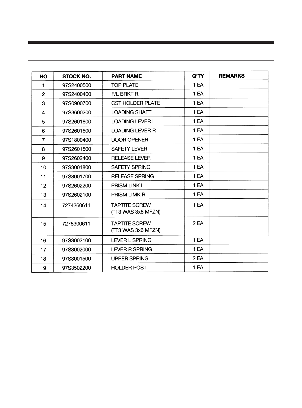
3. EXPLODED VIEW OF F/L ASS'Y.................................................................................................. .....................................48
4. PARTS LIST OF F/L ASS'Y................................................................................................................................................ 49
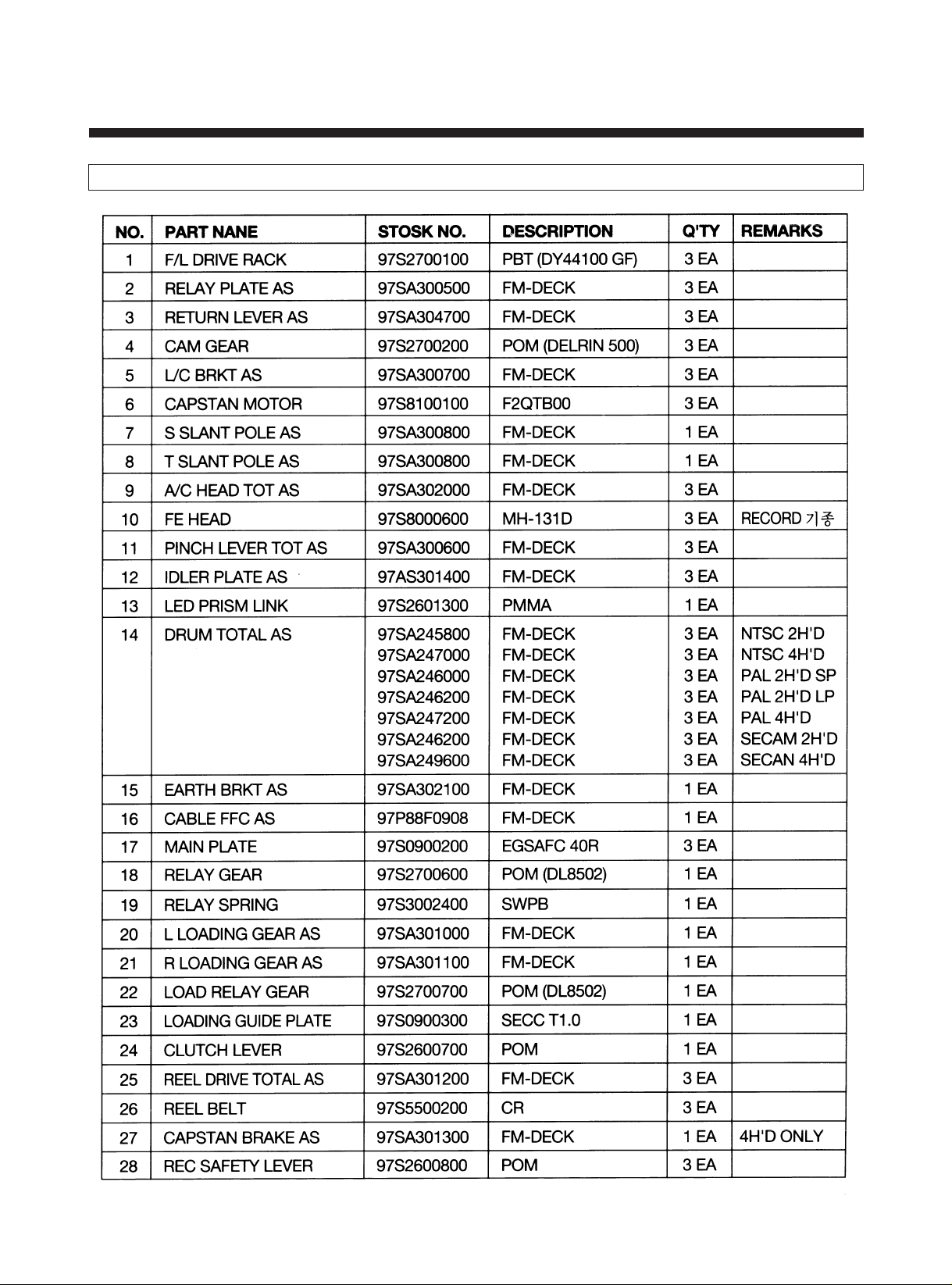
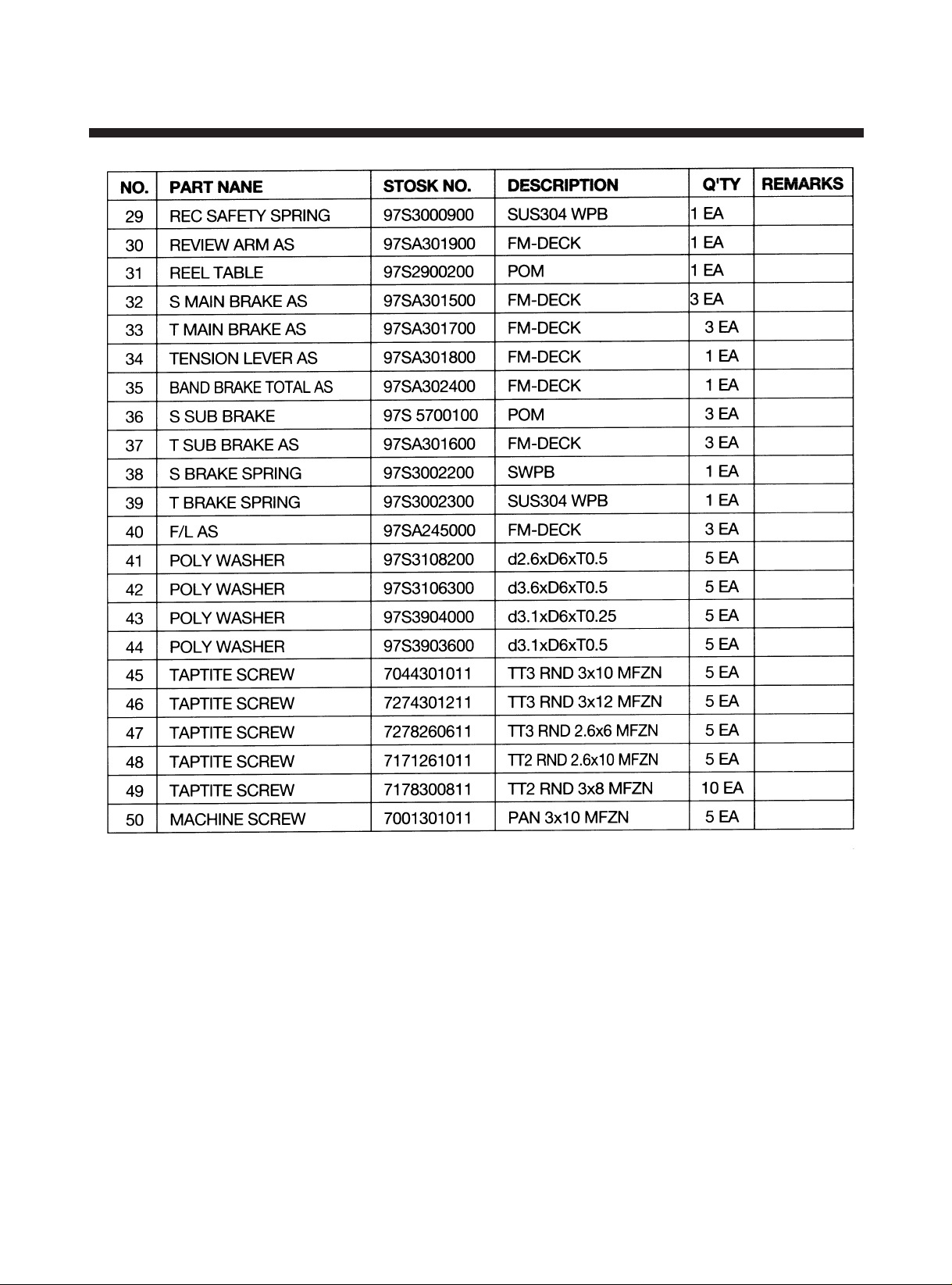
5. MAIN SPARE PARTS LIST OF DECK ASS'Y......................................................................................... ...........................50
SERVICE NOTICE...................................................................................................................................................................52
1
Page 3

1. DESCRIPTION OF THE MECHANISM
1. CHARACTERISTIC OF THE FM-DECK MECHANISM
1) FM-MECHA DECK follows the VHS standard and PAL standard.
2) FM-MECHA DECK has 3 motors (DRUM MOTOR, CAPSTAN MOTOR and L/C MOTOR).
3) FM-MECHA DECK uses L/C MOTOR to drive FRONT LOADING.
4) FM-MECHA DECK has 7 MODES (EJECT/INITIAL/IDLE/REV/SLOW/PLAY/FF & REW) and each mode is composed of
4 bit mode Signals and realized by the mode switch which is driven by the L/C MOTOR.
5) FM-MECHA uses the FULL LOADING system in which mode shifting time (especially, picture appearing time) is short.
6) FM-MECHA DECK is removed the DECK PCB and connected to MAIN PCB by using the B to B TYPE CONNECTOR.
2
Page 4
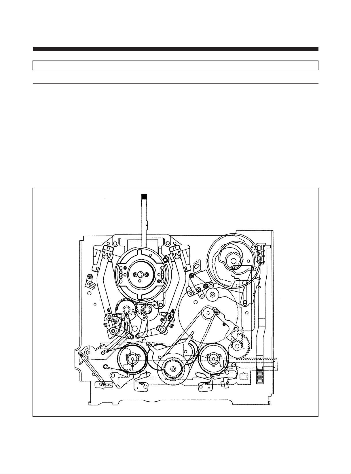
2. DESCRIPTION OF THE MODE
1) EJECT MODE
A. In this mode, the cassette In/Out operation is performed by the CW/CCW rotation of the L/C motor to which the Front
Loading driving parts are directly related.
• CASSETTE IN : If the cassette is inserted into the entrance with proper insertion force, Mode Switch is rotated by
insertion force and break from Eject mode.
At the same time the Cassette In is detected. And instantely the cassette loading is performed and
the L/C motor proceeds to the PLAY/STOP mode.
• CASSETTE OUT: In this state the Cassette Holder is located at the enterance of the front panel, and only the Cassette
In operation can be excuted.
B. Mechanical Arrangement
a. The BAND BRAKE is released from the S REEL TABLE.
b. The S & T MAIN BRAKE is released from the S & T REEL TABLE.
c. The S & T SUB BRAKE is released from the S & T REEL TABLE.
d. The IDLER GEAR is separated from the S & T REEL TABLE.
EJECT MODE
3
Page 5
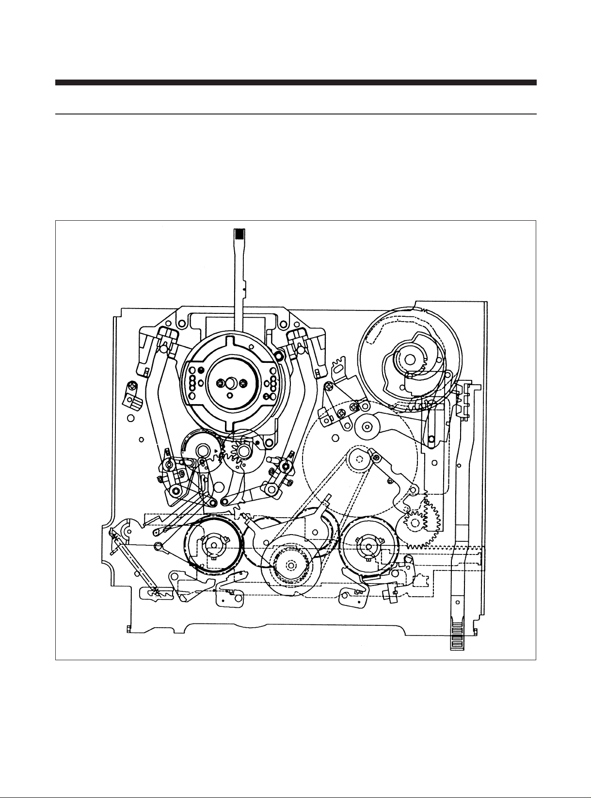
2) INITIAL MODE
A. This mode is used as a reference mode for unloading location when power is off.
B. Mechanical Arrangement
a. The BAND BRAKE is released from the S REEL TABLE.
b. The S MAIN BRAKE is released from the S REEL TABLE.
c. The T MAIN BRAKE is applied to the T REEL TABLE.
d. The S & T BRAKE is released from the S & T REEL TABLE.
INITIAL MODE
4
Page 6
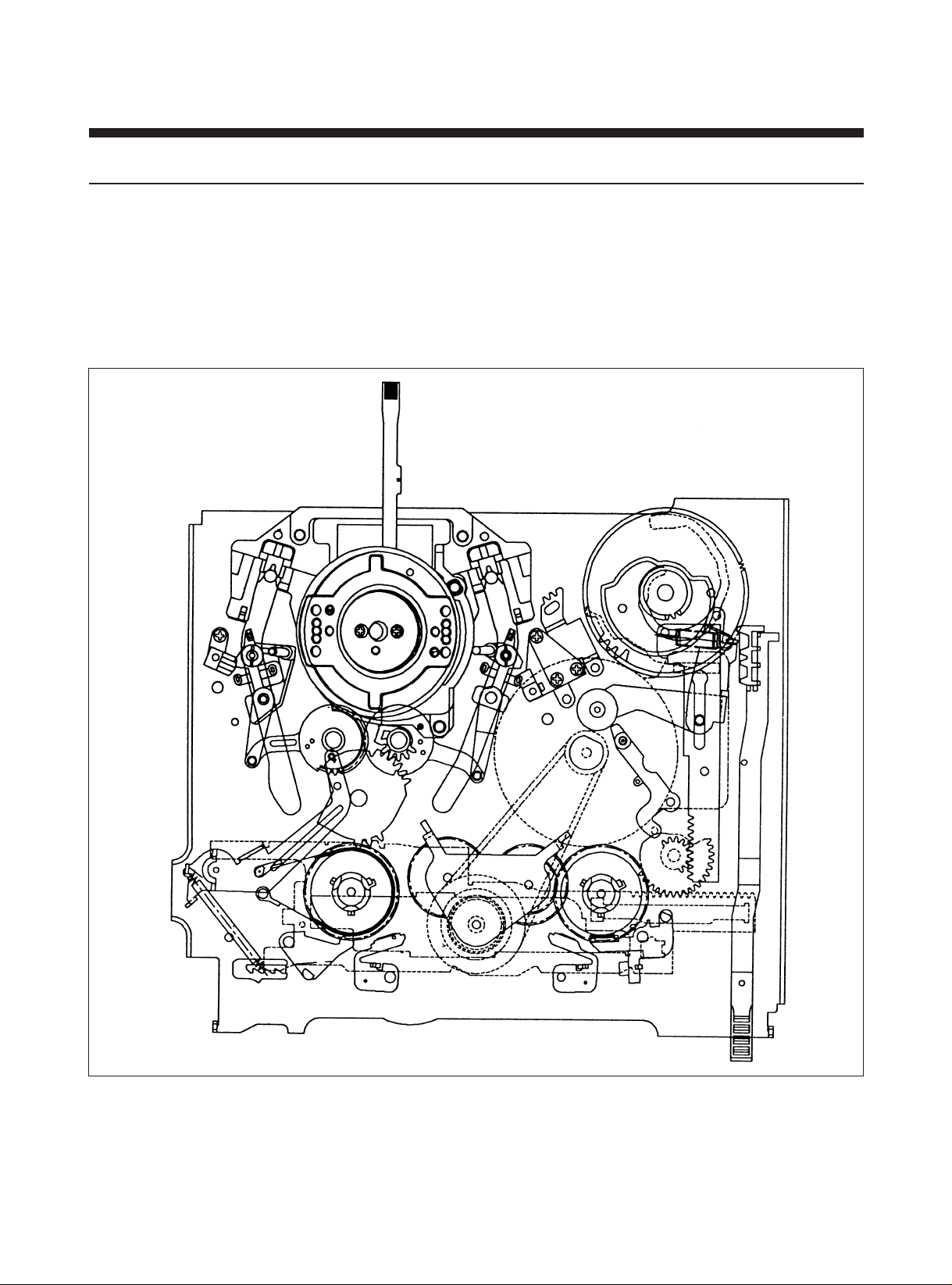
3) LOADING SECTION
A. LOADING SECTION is used to lead a tape to either transporting situation or initial situation by forwarding and
backwarding of POLE BASE AS.
B. Mechanical Arrangement
a. The BAND BRAKE is released from the S REEL TABLE.
b. The S & T MAIN BRAKE is released from the S & T REEL TABLE.
c. The S & T SUB BRAKE is applied to the S & T REEL TABLE.
d. The IDLE GEAR is separated from the S & T REEL TABLE.
LOADING MODE
5
Page 7
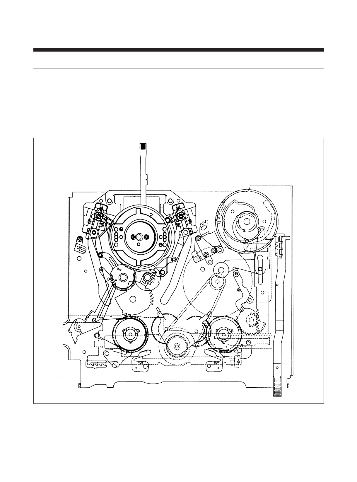
4) IDLE MODE
A. Idle mode is used to reduce the tape tension and load in drum and posts which are used for tape transportation by
seperating PINCH ROLLER from CAPSTAN SHAFT when DECK is performed from forward tape running to backward
tape running or from backward tape running to forward tape running.
B. Mechanical Arrangement
a. The S & T MAIN BRAKE is released from the S & T REEL TABLE.
b. The S & T SUB BRAKE is applied to the S & T REEL TABLE.
C. The PINCH ROLLER is separated from the CAPSTAN SHAFT.
IDLE MODE
6
Page 8
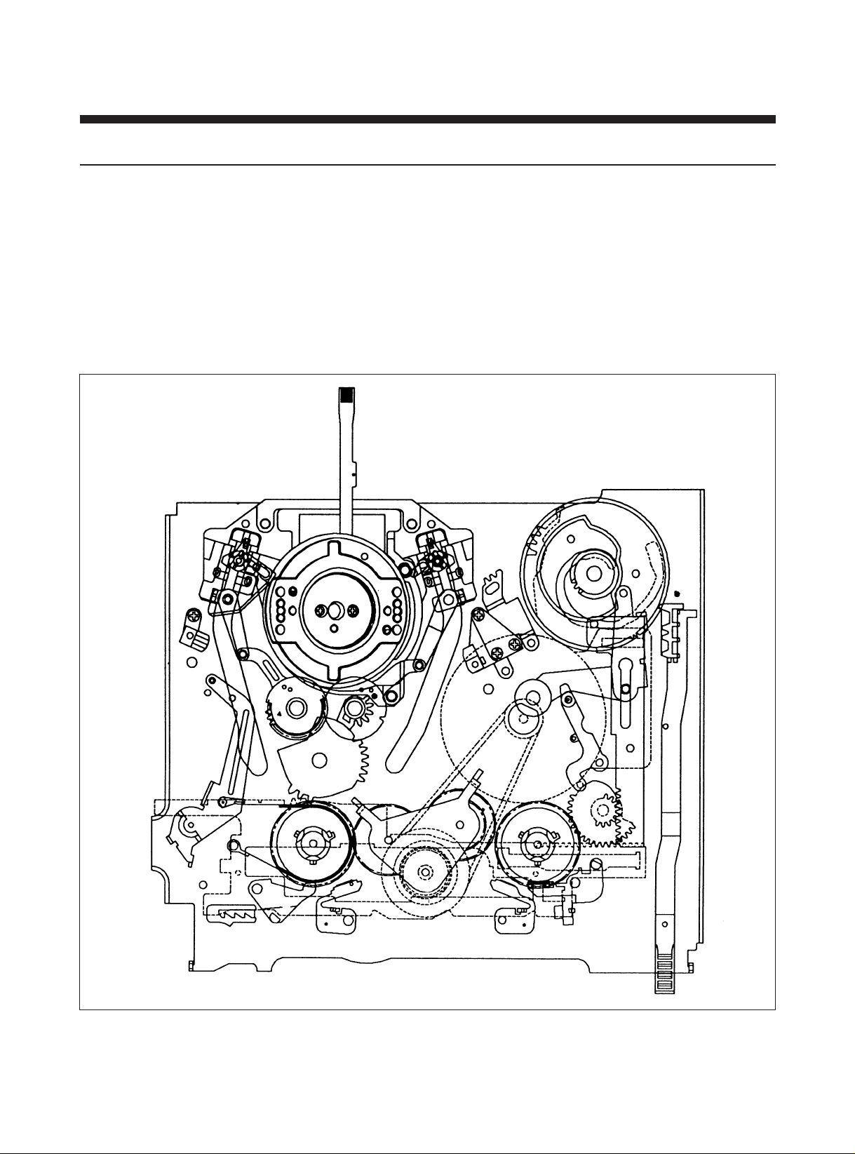
5) REVIEW MODE
A. The Review Search operation is performed in this mode. This mode is obtained by pressing the REW button in the state
of playing. The L/C motor rotated until the Cam switch detects the REVIEW mode. When the Cam switch detects the
REVIEW mode, the L/C motor is stopped and at the nearly time the Capstan starts to rotate CCW to transport the tape
reversely.
B. Mechanical Arrangement
a. The BAND BRAKE is released from the S REEL TABLE.
b. The S & T MAIN BRAKE are released from the S & T REEL TABLE.
c. The S SUB BRAKE is applied to the S REEL TABLE.
d. The PINCH ROLLER is applied to the CAPSTAN SHAFT to transport the tape reversely.
e. The REVIEW ARM is moved forward to perform the role of the tape transporting POST.
REVIEW MODE
7
Page 9
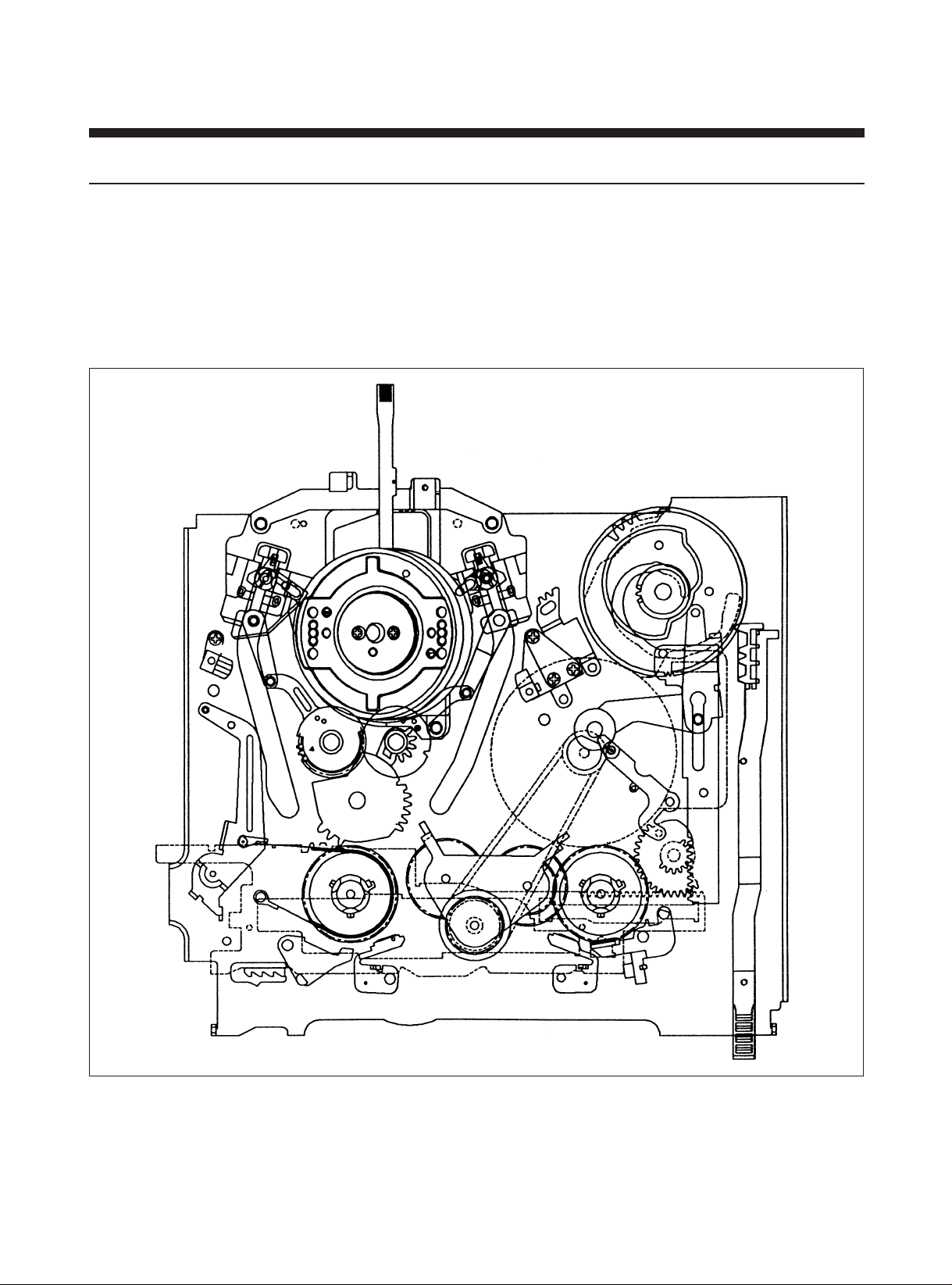
6) SLOW MODE
A. This mode is performed the forward and backward slow searching.
B. Mechanical Arrangement
a. The BAND BRAKE is applied to the S REEL TABLE.
b. The S & T MAIN BRAKE is released from the S & T REEL BRAKE.
c. The S & T SUB BRAKE is released from the S & T REEL TABLE.
d. The REVIEW ARM is located at the initial position.
e. The CAPSTAN BRAKE is applied to the CAPSTAN MOTOR.
F/R SLOW MODE
8
Page 10
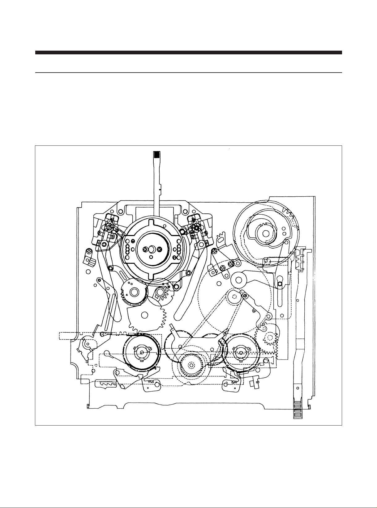
7) PLAY/RECORD/STOP MODE
A. The PLAY/RECORD/STOP mode transport the tape from the S REEL TABLE to the T REEL TABLE in the regular speed
to perform the recording and playback. Also this mode is to STAND-BY the next operation of key-in.
B. Mechanical Arrangement
a. The TENTION POLE is located at the appointed position.
b. The BAND BRAKE is applied to the S REEL TABLE for excute the tape tension servo.
c. The S & T MAIN BRAKE ans S & T SUB BRAKE is released from the S & T REEL TABLE.
d. The PINCH ROLLER is applied to the CAPSTAN MOTOR.
PLAY MODE
9
Page 11
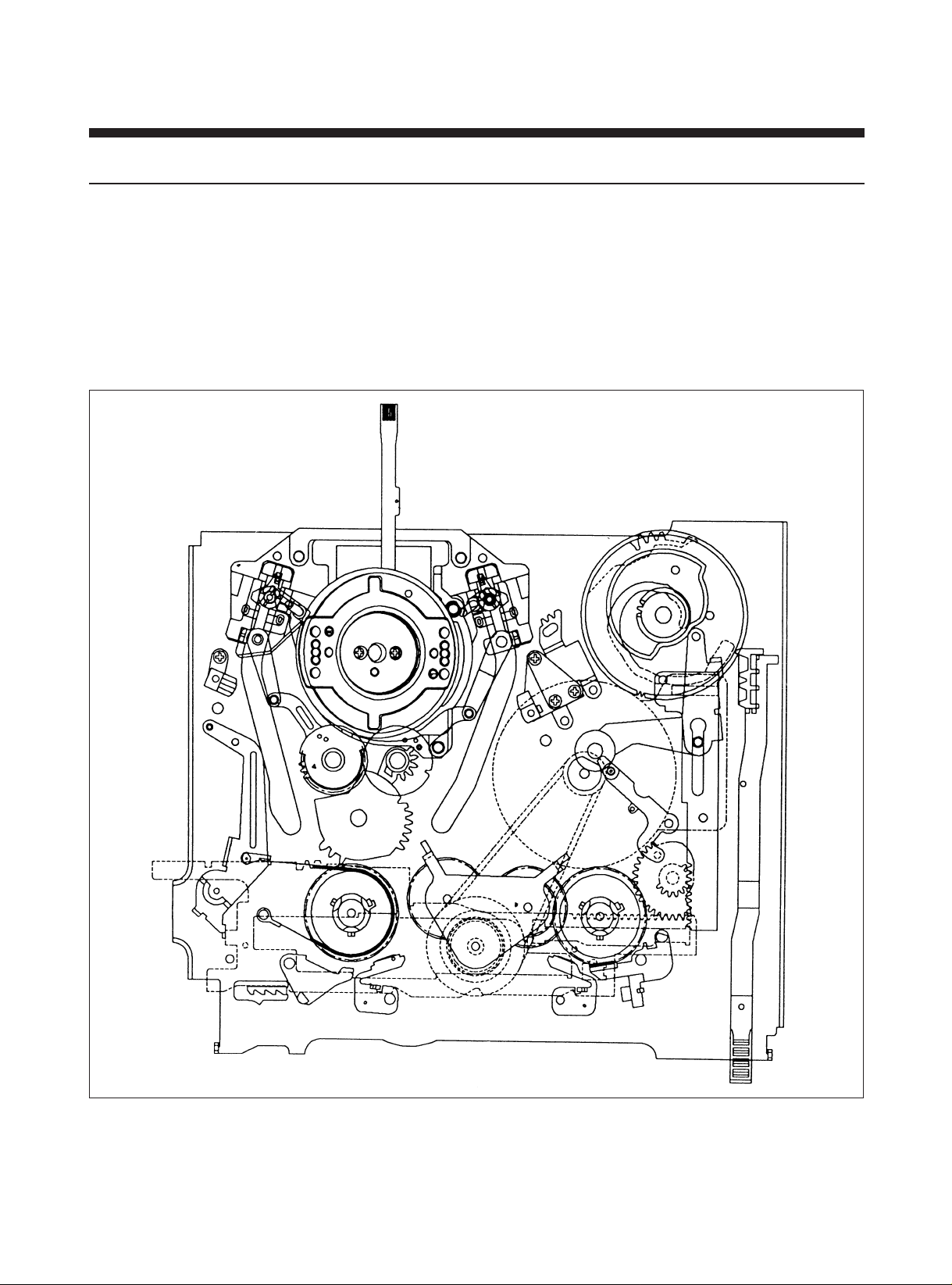
8) BRAKE MODE
A. This mode is a mechanical mode which lies in between PLAY mode and FF/REW mode.
If EJECT, STOP or PLAY button is pressed in the FF/REW mode, S & T MAIN BRAKES are applied to the S & T REEL
TABLE quickly. So, It can be prevented to loosen of the tape.
B. Mechanical Arrangement
a. The BAND BRAKE is released from the S REEL TABLE.
b. The S & T MAIN BRAKE are applied to the S & T REEL TABLE.
c. The S & T SUB BRAKE are released from the S & T REEL TABLE.
d. The PINCH ROLLER is released from the CAPSTAN SHAFT.
BRAKE MODE
10
Page 12
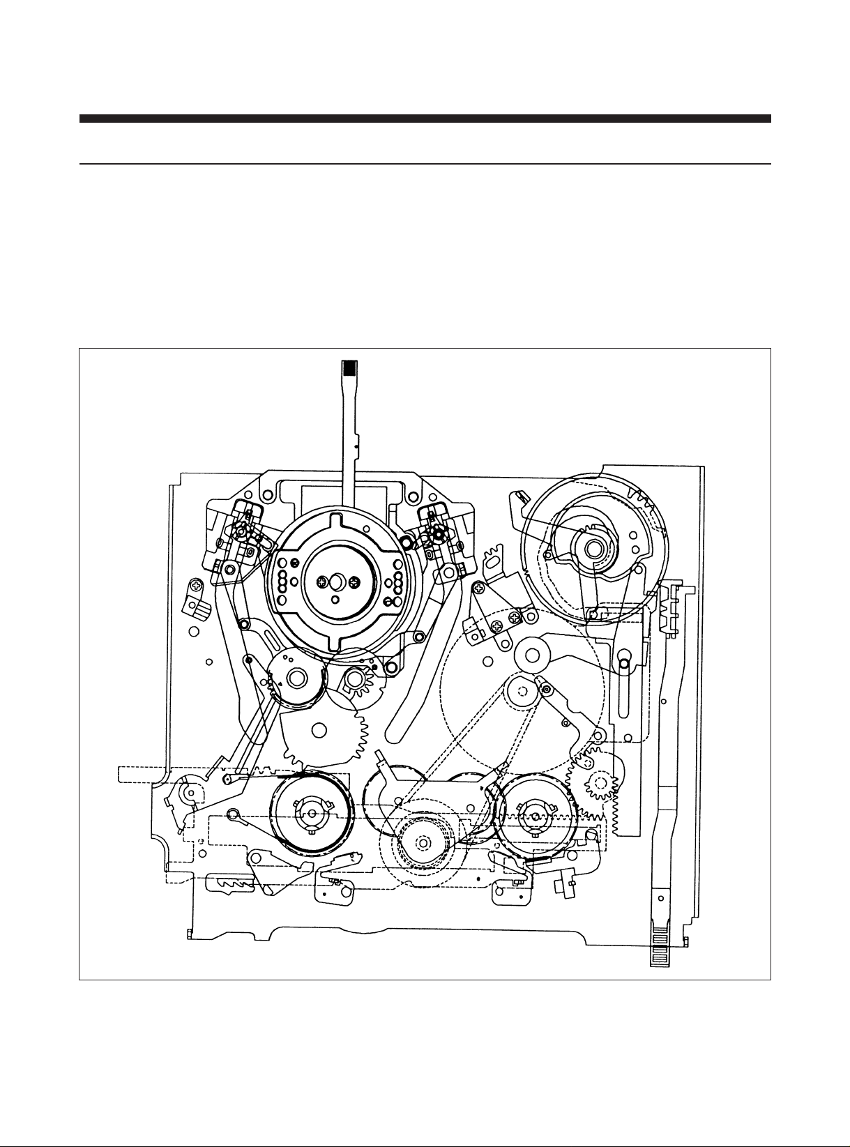
9) FF/REW MODE
A. In this mode, the cassette tape is rewound to the S & T REEL Table at the high speed by the CW/CCW rotation of the
Capstan Motor which is directly releated to the S & T REEL Table.
If the START/END SENSOR is on during this operation, it returns to the STOP MODE and excutes CUE/REV.
During the FF/REW operation, the Drum continues to rotate with the tape wrapped around it and the tape is contacted
to the CONTROL HEAD that reads the VISS signal.
B. Mechanical Arrangement
a. The BAND BRAKE and the S & T MAIN BRAKE are released from the S & T REEL TABLE.
b. The PINCH ROLLER is separated from the CAPSTAN SHAFT.
FF/REW MODE
11
Page 13
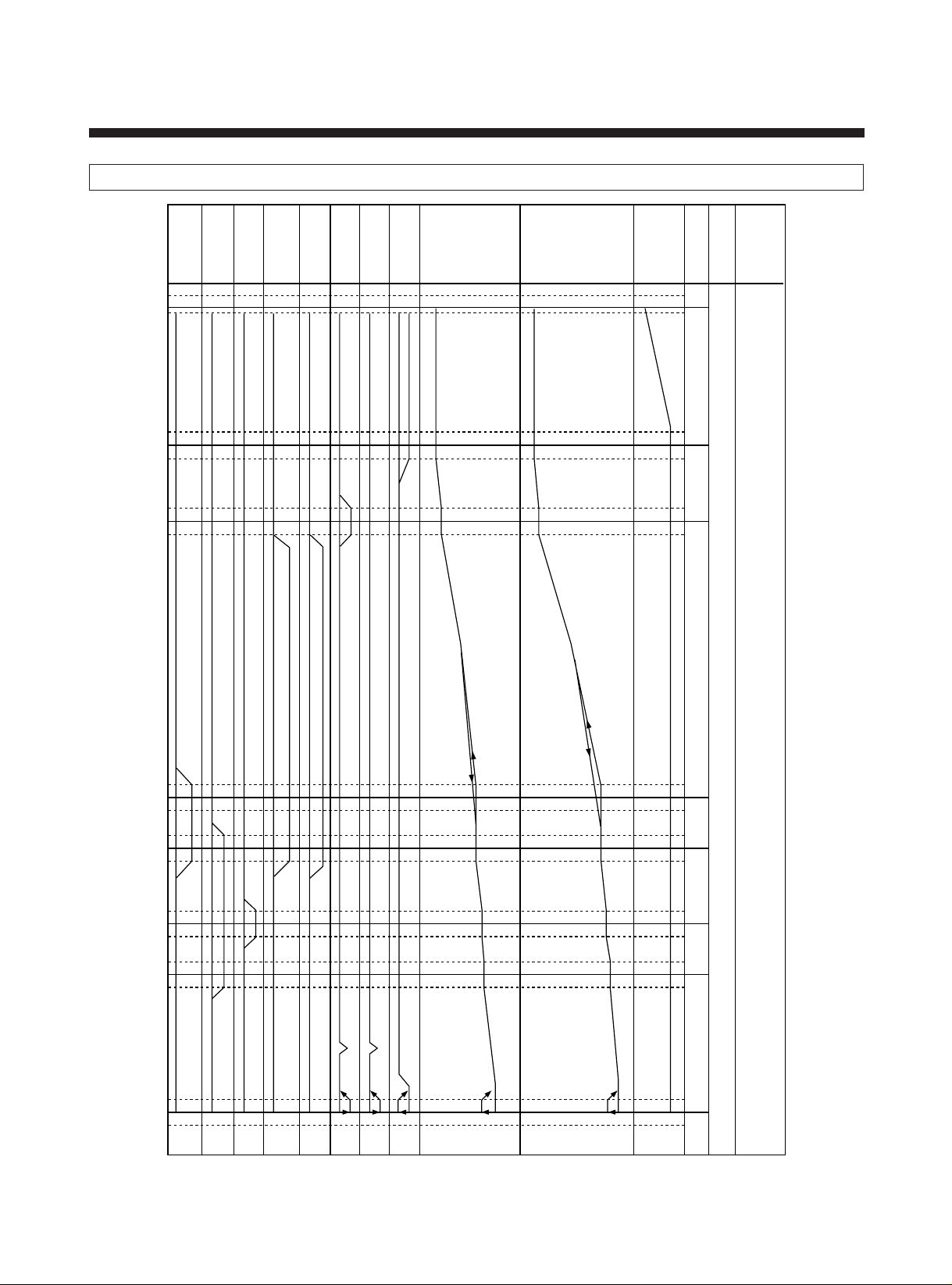
3. FM DECK TIMING CHART
. . . . . . . . . . . . . . . . . . . . . . .
. . . . . . . . . . . . . . . . . . . . . . . .
. . . . .
. . . . . .
. . . . . . . . . . . . . . . . . . . . . . . . . . . . . . . . . . . . . . . . . . . . . . . .
. . . . . . . . . . . . . . . . . . . . . . . . . . . . . . . . . . . . . . . . . . . . . . . . .
. . . . . . . . . . . . . . . . . . . . . . . . . . . . . . . . . . . . . . . . . . . . . . . . . .
. . . . . . . . . . . . . . . . . . . . . . . . . . . . . . . . . . . . . . . . . . . . . . . .
. . . . . . . . . . . . . . . . . . . . . . . . . . . . . . . . . . . . . . . . . . . . . . . . .
. . . . . . . . . . . . . . . . . . . . . . . . . . . . . . . . . . . . . . . . . . . . . . . . . .
. . . . .
. . . . . .
. . . . . . . . . . . . . . . . . . . . . . .
. . . . . . . . . . . . . . . . . . . . . . . .
. . . . . . . . . . . . . . . . . . . . . . . . .
. . . . . . . . . . . .
. . . . . . . . . . . . .
. . . . . . . . . . . . . .
MODE
MODE
CAM ANGLE
F/L RACK
RELAY CAM
MAIN PLATE
REEL
DRIVE
S MAIN
BRAKE
T MAIN
BRAKE
S SUB
BRAKE
T SUB
BRAKE
CAP. BRAKE
PINCH
REV ARM
L
L
L
L
L
L
L
0
DIRECT
8
34.1
9.7
3.97
SLIP
5.6
13.3
10.4
13.7
18.25
19.9
22.5
23.6
23.92
27.77
33.83
36.4
26.6
25.3
43.4
40.37
–5
2
70
80
100
110
210
220
230
240
260
270
280
290
335
345
340
285
265
235
215
105
75
0
EJECT
INITIAL
(LOADING)
IDLE
REV
SLOW
PLAY
/STOP
FF/REW
(BRAKE)
12
Page 14
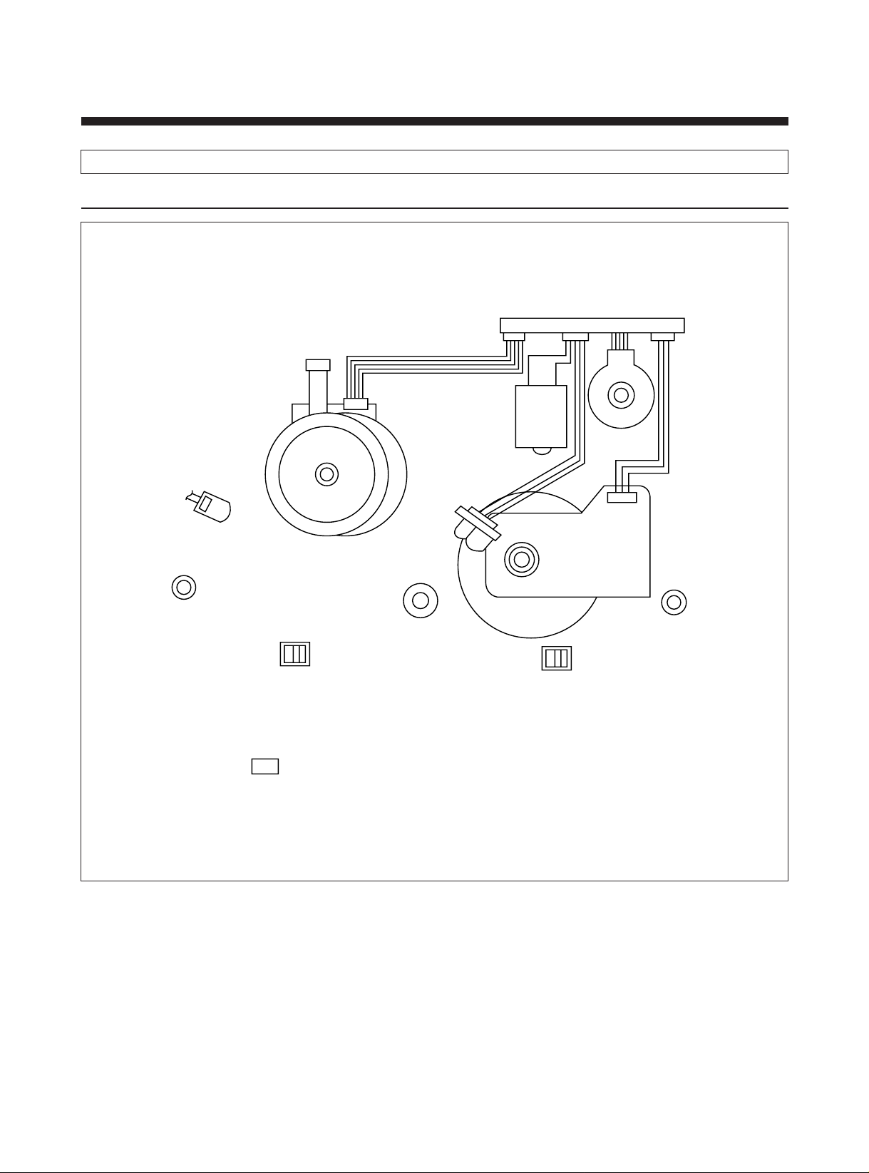
DRUM MOTOR
CN-A
CN-C1 CN-C2
CAM SW
L/C MOTOR
ACE HEAD
CAPSTAN MOTOR
START SENSOR
(MAIN PCB)
REEL SENSOR
(MAIN PCB)
LED (MAIN PCB)
REEL SENSOR
(MAIN PCB)
SWITCH DETECTOR
(MAIN PCB)
END SENSOR
(MAIN PCB)
FE HEAD
CN-B
4. WIRING DIAGRAM
1) WIRE DIAGRAM
13
Page 15

2) CONNECTOR PIN ARRANGEMENT
CN-A (2 HEAD MONO: ELCO) CN-C1 (TAICO) CN-2 (TAICO)
1 VR 1
2 COMMON
3 VL 1
4 GND
CN B (JAE)
1 FE HEAD
2 GND
1 DRUM FG
2 DRUM M/T GND
3 DRUM PG
4 DRUM SPP CTL
5 DRUM M/T 12V
6 CAM A
7 CAM B
8 CAM C
9 CAM D
10 LM (+)
11 LM (—)
12 A/E HEAD
13 AUDIO GND
14 AUDIO HEAD
15 AUDIO HEAD
16 CTL HEAD (—)
17 CTL HEAD (+)
18 CAP CTL REF
1 CAPSTAN I LM.
2 CONTROL
3 CAP IC GND
4 CAP M/T GND
5 CAPSTAN F/R
6 CAPSTAN FG
7 EVER 5V
8 CAP M/T 12V
14
Page 16
2. ARRANGEMENT AND CHECK FOR
THE MAJOR PAR TS
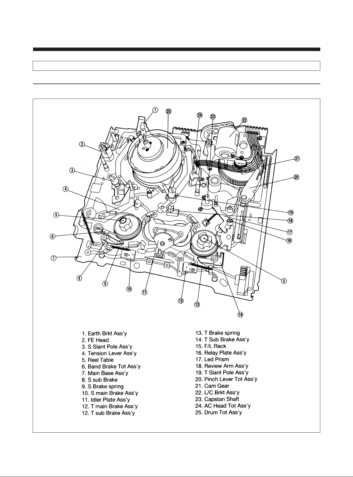
1. P AR TS LOCATION
1) PARTS LOCATION OF DECK ASS?Y
A. TOP VIEW
15
Page 17
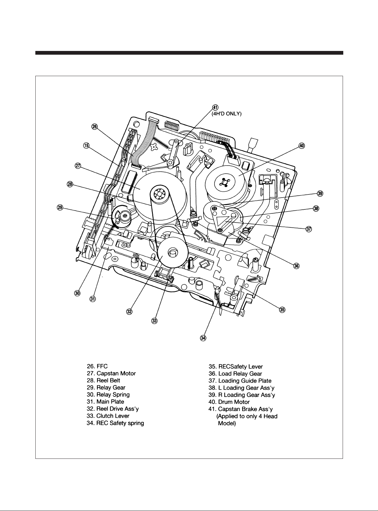
B. BOTTOM VIEW
16
Page 18
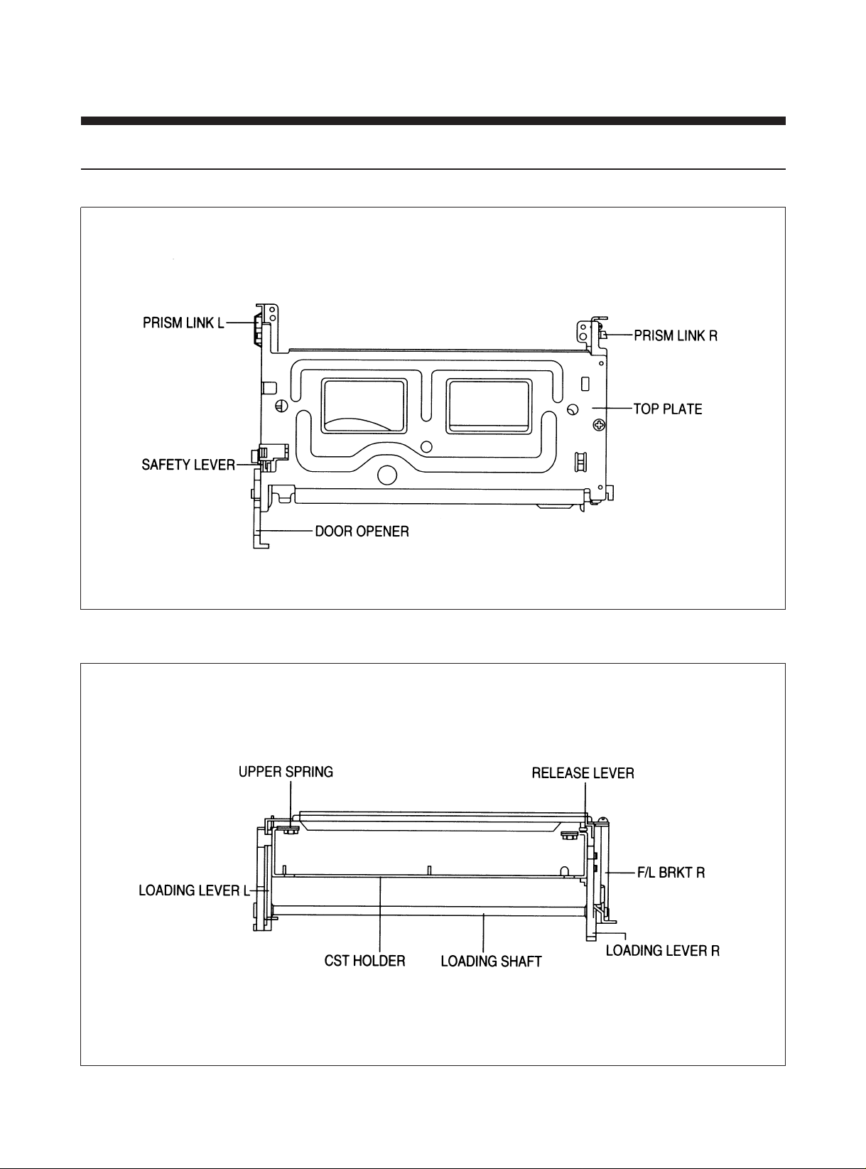
2) PARTS LOCATION OF FRONT LOADING ASS?Y
A. TOP VIEW
B. FRONT VIEW
17
Page 19

2. PERIODIC MAINTENANCE AND SERVICE SCHEDULE
1) PERIODIC MAINTENANCE AND SERVICE SCHEDULE
A. In order to effectively maintain the excellent performance and fully utilize the features of this apparatus, and to lengthen
the life of mechanism and tapes, we strongly urge you to perform the periodic maintenance and inspection as
described below.
– After repairing, do the maintenance as described below irrespective of the length of time in use.
B. Cleaning of the Head Drum Ass'y
– Clean the Drum assembly with a cleaning cloth soaked in liquid cleaner (alcohol) by placing lightly against the Drum
slowly revolving the rotating HEAD DRUM Ass'y by hand (Do not rotate it by applying the electric power to the motor
for cleaning).
– Do not move the cleaning cloth in the vertical direction against the heat-tip.
C. Cleaning of the tape transporting section
Cleaning the tape transporting parts with a cleaning cloth soaked in the alcohol.
D. Cleaning of driving section
Cleaning the driving section with the cloth soaked in the alcohol.
E. Routine inspection
Perform the maintenance and inspection as separately described depending on the period of time in use.
2) CLEANING AND LUBRICATION
A. Cleaning of Tape Transporting System
a. Cleaning of Tape Tranporting System
– Following parts should be cleaned every 500 hours of use.
•
TENSION POLE
• S GUIDE POST • VIDEO HEAD/DRUM • T GUIDE POST
• FE HEAD • T SLANT POLE • CAPSTAN SHAFT
• S GUIDE ROLLER • T GUIDE ROLLER • PINCH ROLLER
–Since the above parts contact with video tape, they tend to collect dust particles if they are stained with dust or
foreign substance it have a bad effect on the picture and lead to demage of the tape.
– After cleaning with alcohol, allow the parts to dry thoroughly before using a cassette tape.
b. Cleaning of driving system
• REEL TABLE • T MAIN BRAKE •CAPSTAN FLYWHEEL/PULLEY
• S MAIN BRAKE • T SUB BRAKE • REEL PULLEY
• S SLANT POLE • AC HEAD/AE HEAD
B. LUBRICATION
• S REEL TABLE POST • T REEL TABLE POST •IDLER POST
–After cleaning components with alcohol, lubricate these with one or two drops oil.
18
Page 20

3) SERVICE SCHEDULE FOR THE MAJOR PARTS
Following parts should be receive perodic service according to the recommended intervals.
NAME
DRUM TOTAL ASS'Y ƒN O ƒN O ƒN
CAPSTAN MOTOR O O
L/C BRKT ASS'Y O O
REEL BELT O O
IDLER PLATE TOTAL ASS'Y ƒN O
REEL TABLE O
T SUB BRAKE ASS'Y O O
BAND BRAKE ASS'Y O O
S MAIN BRAKE ASS'Y O O
T MAIN BRAKE ASS'Y O O
PINCH ROLLER ASS'Y ƒN O ƒN
PERIODIC SERVICE (TIME)
1000 2000 3000 4000 5000
AC HEAD ASS'Y O
FE HEAD O
REEL GEAR TOTAL ASS'Y ƒN O
ƒN: Check and Replace if necessary O: Replace
Note: Even though the unit is not used frequently, cleaning, lubrication and replacement of the belt should be
undertaken every 2 years.
19
Page 21

3. JIGS AND TOOLS
1) LIST OF JIGS AND TOOLS
NO ITEMS MODEL FIG. NO REMARKS
1 ALIGNMENT TAPE PAL: SP MONOSCOPE 6 KHz ! CHECKING OF THE TAPE
SP COLOR BAR 1KHz TRANSPORTING SYSTEM
(LP MONOSCOPE)
2 CLEANING TAPE DHC-602V @ CLEANING OF THE TAPE
TRANSPORTING SYSTEM
3 CASSETTE TAPE KT-300NV # MEASUREMENT OF
(KOKUSAI) KT-300RV REEL TORQUE
4 VHS SPINDLE HEIGHT TSH-V4 $ MEASUREMENT OF
GAUGE REEL TABLE HEIGHT
5 TENTELO METER T2-H7-UM % MEASUREMENT OF THE
(TENTELO) BACK TENSION
6 FAN TYPE TENSION BELOW 3KG ^ MEASUREMENT OF THE
METER PRESSING FORCE FOR THE
PINCH ROLLER
7 DENTAL MIRROR & CHECKING OF THE TAPE
TRANSPORTING SYSTEM
8 + DRIVER * -1 ASSEMBLY, DISASSEMBLY
– DRIVER * -2 AND ADJUSTMENT
ADJUSTMENT DRIVER * -3
9 SERVICE JIG S/N: 97PD103500 ( CHECK OF THE DECK
MECHANISM OPERATION
20
Page 22
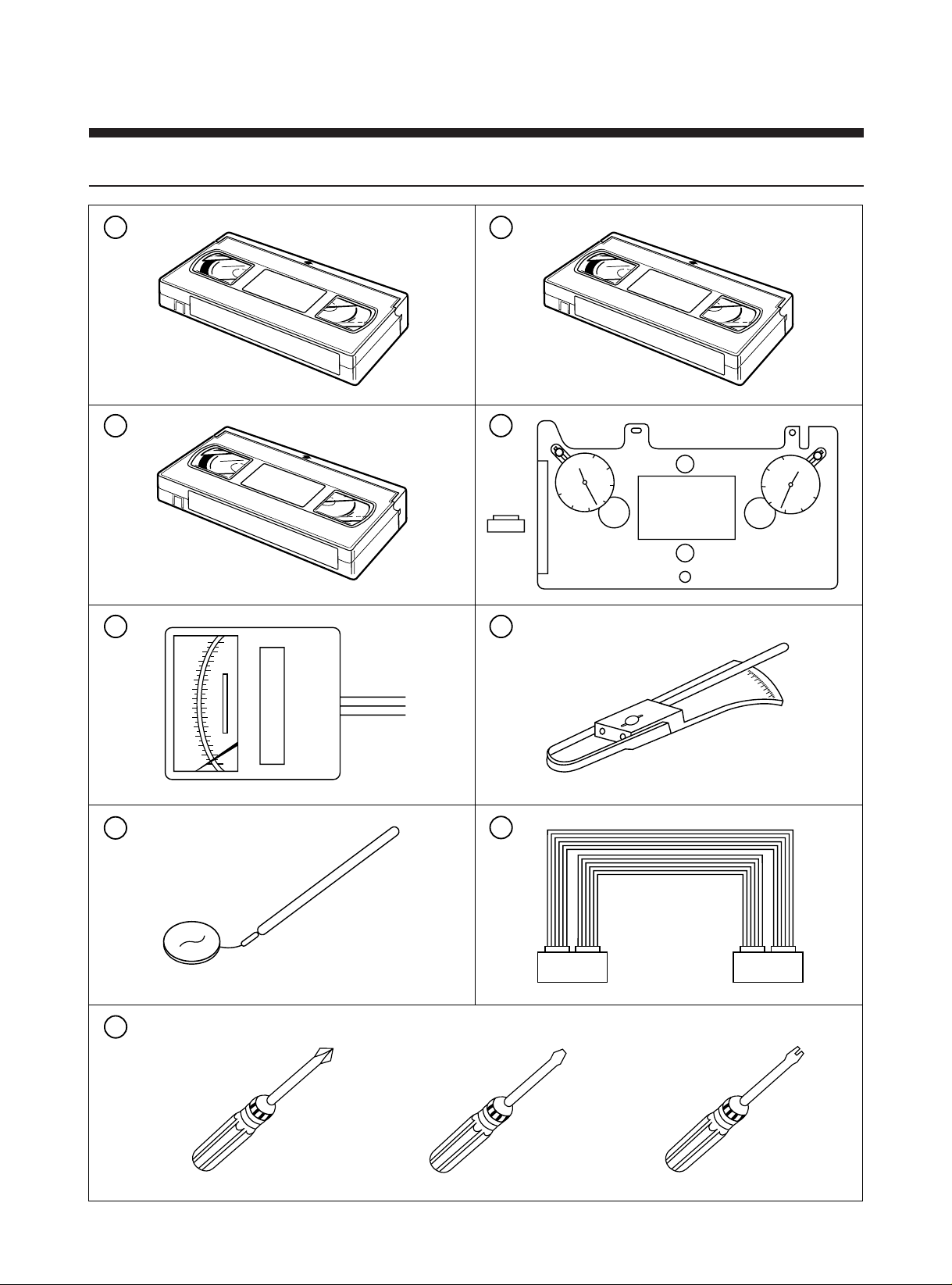
2) SKETCH OF JIGS AND TOOLS
ALIGNMENT TAPE
CLEANING TAPE
30
20
10
0
10
20
30
30
20
10
0
10
20
30
VHS SPINDLE
HEIGHT GAGE
1
2
3
4
5 6
7
8
8-1
8-2
8-3
9
21
Page 23
3. DISASSEMBLY AND REPLACEMENT
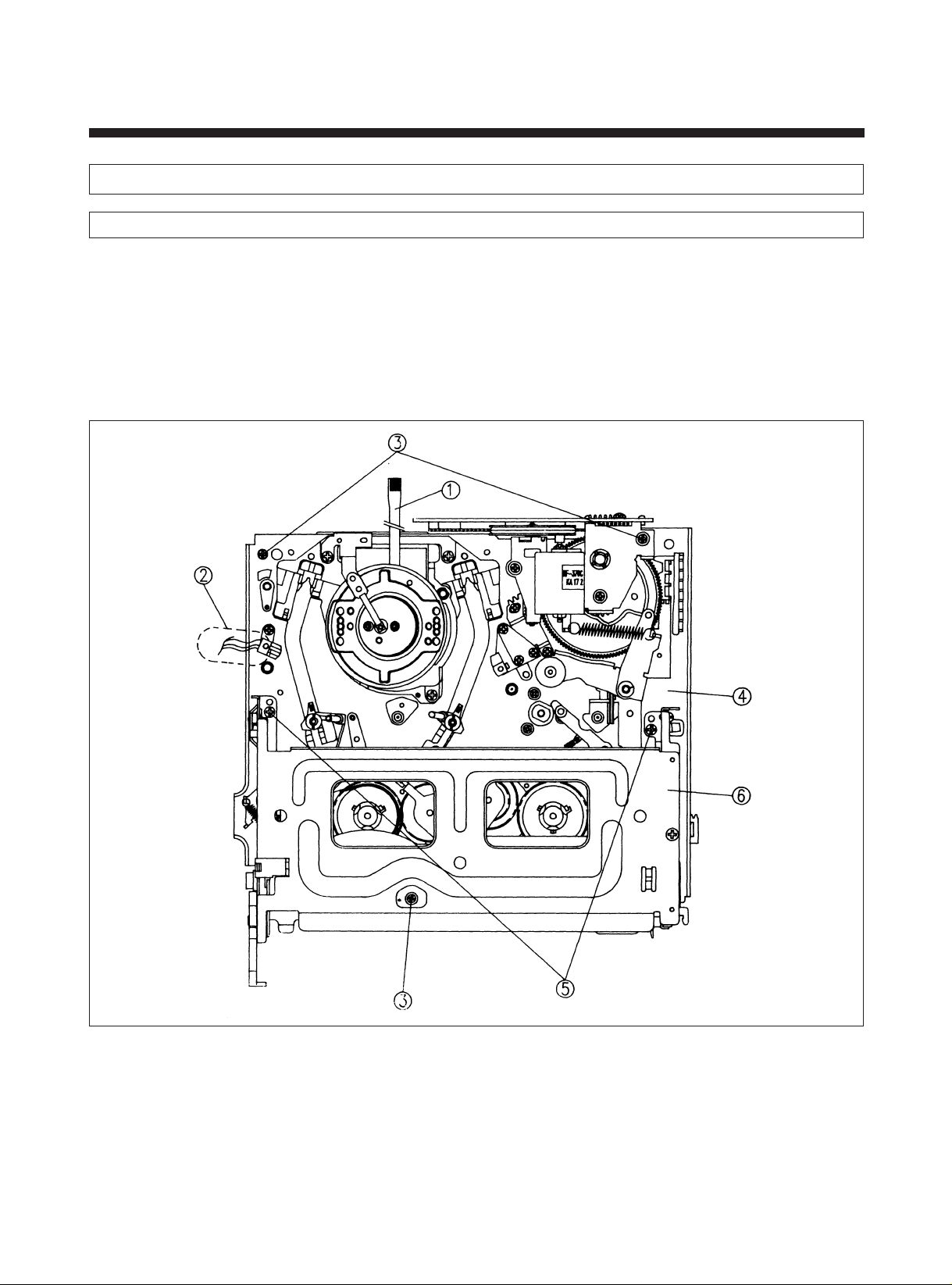
CAUTION : The DECK MECHANISM can be removed only in the EJECT mode.
1. DISASSEMBLY OF THE DECK TOT AL ASS?Y AND F/L ASS?Y
1) Remove the top cover and front panel, BRKT F/L, BRKT DECK.
2) Separate the Drum FPC ! and F/E HEAD CONNECTOR @ .
3) Remove the 3 screws # and disassemble the DECK $ .
4) Remove the 2 screws % from the F/L ASS?Y.
5) Remove F/L ASS?Y from the Hook which is formed in the Main Base by pushing it while pulling the upper part of F/L
ASS?Y ^ .
NOTE:
• Please be careful not to bend or deform the Hooks formed in the MAIN BASE and Claws in the F/L Ass?y.
(See Fig. 3-1)
Fig. 3-1
22
Page 24
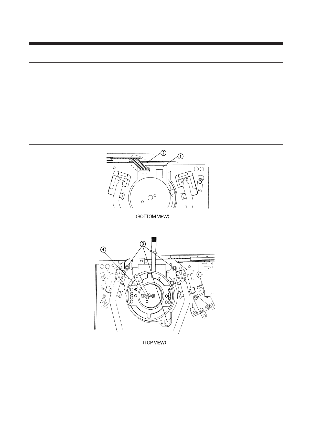
2. REPLACEMENT OF THE DRUM TOT AL ASS?Y
1) Turn over the DECK ASS?Y.
2) Separate the L/C-DRUM CONN. AS @ from the DRUM PCB ! .
3) Turn over the DECK ASS?Y again and remove the 3 screws # and remove the DRUM TOTAL ASS?Y $ .
4) After changing new DRUM ASS?Y please assemble it in the reverse order.
5) After completing this procedure, check and confirm the state of tape running and adjust the tape transporting system
(Refer to SEC. 5) if necessary.
NOTE:
• Avoid damaging the HEAD or getting the HEAD dirty.
• If playback picture is poor, try cleaning the HEAD and checking the connectors before replacing DRUM ASS?Y.
• Don?t replace only upper Drum for Service.
• Please replace Drum Total Ass?y.
(See Fig. 3-2)
Fig. 3-2
23
Page 25
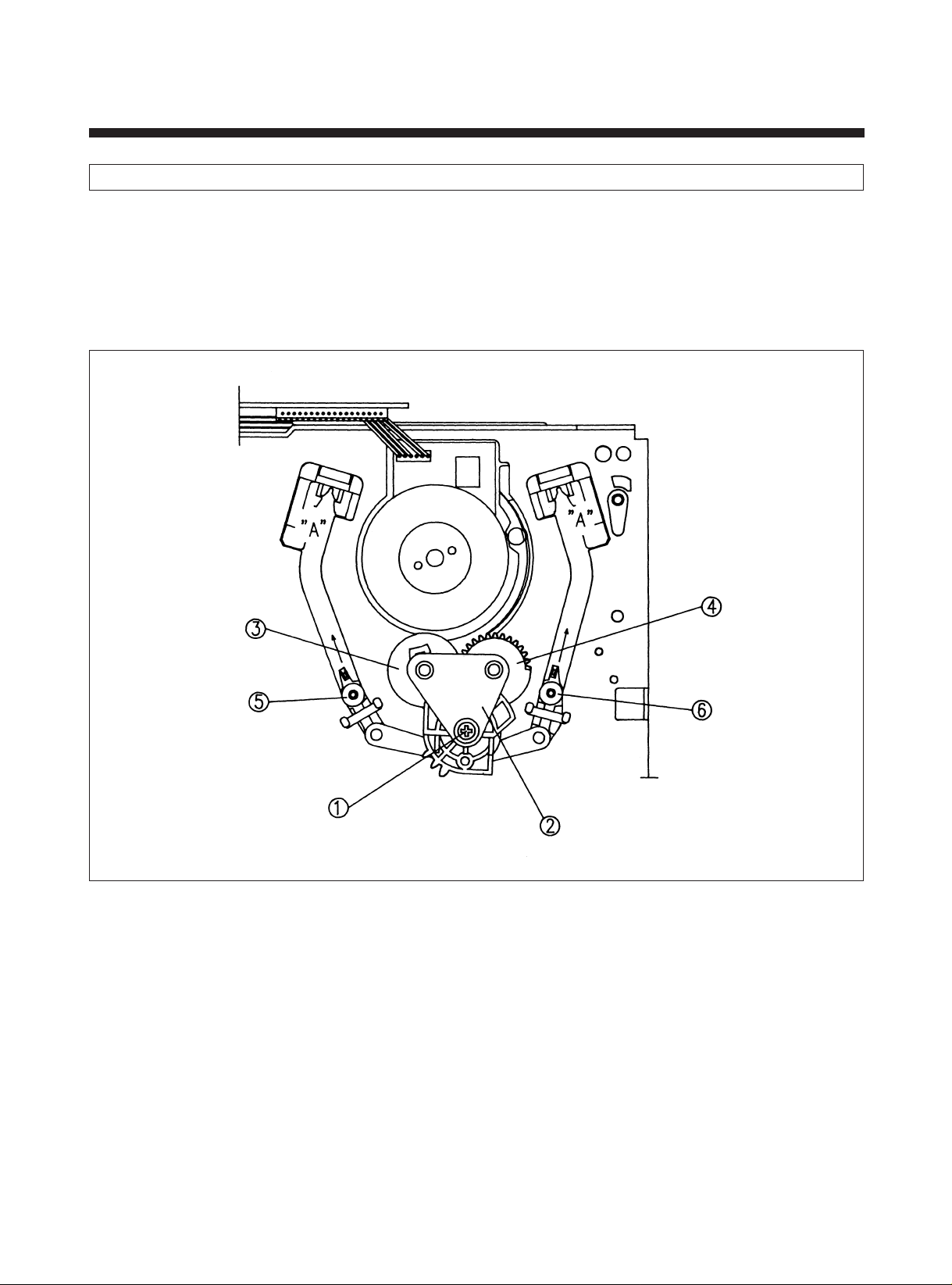
3. REPLACEMENT OF THE S, T SLANT POLE ASS?Y
1) Remove the DRUM TOTAL ASS?Y according to the method of the SEC. 3-2.
2) Remove the 2 screws ! and the LOADING GUIDE PLATE @ .
3) Remove the R & L LOADING GEAR ASS?Y # , $ .
4) Remove the S & T SLANT POLE ASS?Y % , ^ after moving them to the point "A" by pulling them in the direction of the
arrow ¨O.
5) After changing new SLANT POLE ASS?Y please assemble it in the reverse order.
6) Be careful not to get grease on the GUIDE ROLLER.
(See Fig. 3-3)
Fig. 3-3
24
Page 26
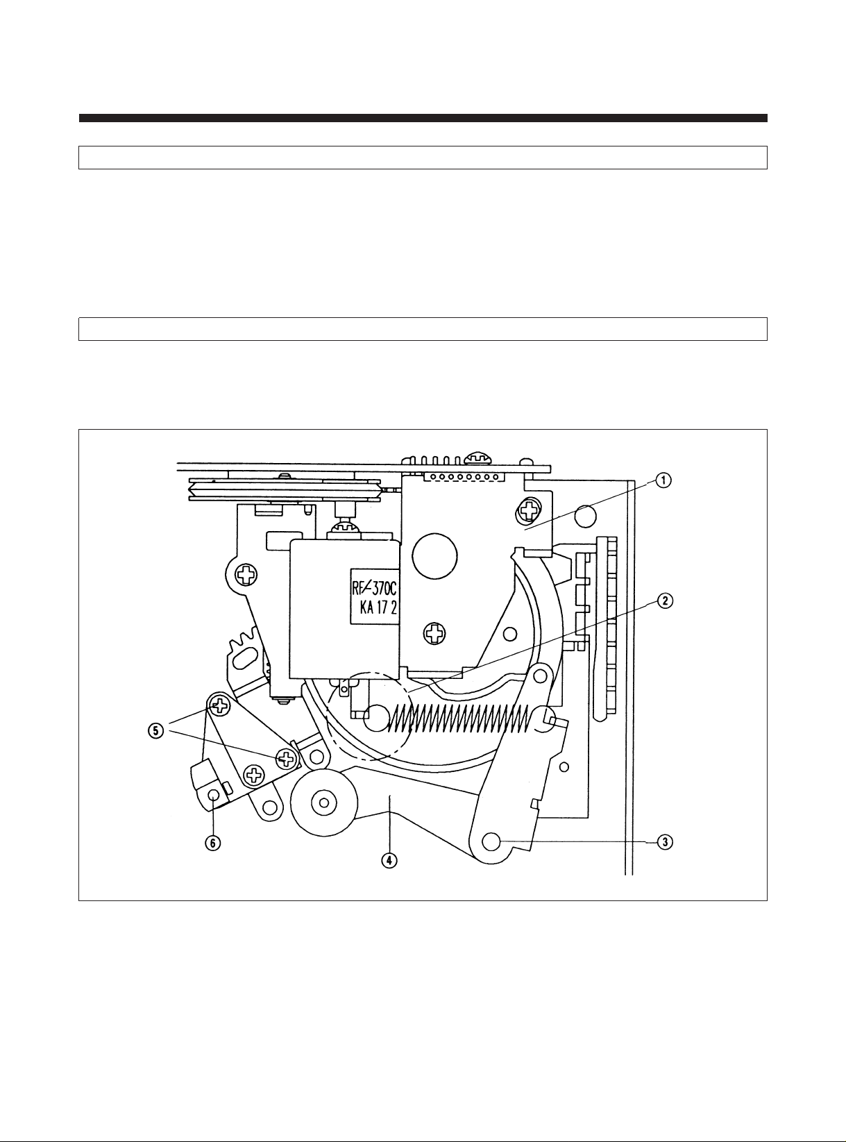
4. REPLACEMENT OF THE PINCH LEVER TOT AL ASS? Y
1) Unhook the PINCH SPRING HOOK @ which is hanging on the L/C BRKT ASS?Y !.
2) After removing the POLY WASHER # disassemble the PINCH LEVER TOTAL ASS?Y $ .
3) After changing new PINCH LEVER TOTAL ASS?Y, assemble it in reverse order.
NOTE:
• Pay attention to be located the BOSS of the PINCH LEVER ASS?Y to the outside of the CAM. (See Fig. 4-2)
• Pay attention to avoid staining with grease or oil on the outside of the PINCH ROLLER.
(See Fig. 3-4)
5. REPLACEMENT OF THE A/C HEAD TOT AL ASS?Y
1) After removing the 2 screws % from the A/C HEAD TOTAL ASS?Y, remove the A/C HEAD TOTAL ASS?Y ^ .
2) After changing new A/C HEAD TOTAL ASS?Y, please assemble it in the reverse order.
3) After changing it, please re-adjust the tape transporting system and audio bios. (Refer to SEC. 5)
(See Fig. 3-4)
Fig. 3-4
25
Page 27
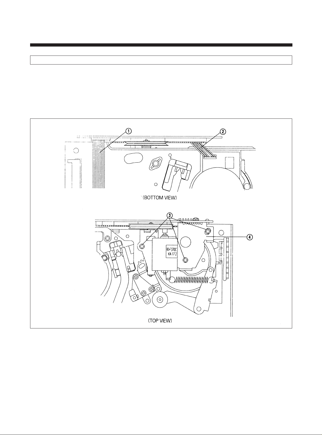
6. REPLACEMENT OF THE L/C BRKT ASS?Y
1) Turn over the DECK.
2) Separate the CAPSTAN EFC ! from the CONNECTOR of the L/C BRKT ASS?Y$ .
3) Separate the L/C-DRUM CONN. AS @ from the CONNECTOR of the DRUM ASS?Y.
4) Return the DECK over.
5) After removing the 3 screws # from the L/C BRKT ASS?Y.
6) After changing to the new L/C BRKT ASS?Y, reassemble the above-mentioned parts in the reverse order.
7) Pay attention to the assembly datum position, when reassembling the MODE SWITCH. (Refer to Fig. 4-2)
(See Fig. 3-5)
Fig. 3-5
26
Page 28
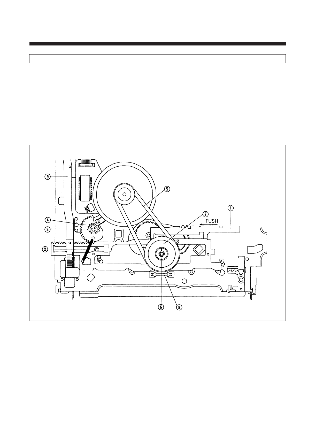
7. REPLACEMENT OF THE MAIN PLA TE
1) After turning over the deck, separate RELAY SPRING @ from the MAIN PLATE ! .
2) After removing the one screw # , disassemble the RELAY GEAR $ .
3) After removing the REEL BELT % , remove the POLY WASHER ^ .
4) Remove the REEL DRIVE TOTAL ASS?Y & and CLUTCH LEVER * .
5) Push the MAIN PLATE to left side and remove it.
NOTE:
• When removing the MAIN PLATE in the state that the F/L RACK is assembled, pay attention to avoid the transformation
of the MAIN PLATE by interfering of each other.
• When reassemblying, pay attention to the assembly position of the MAIN PLATE and RELAY GEAR. (See Fig. 4-3)
• Before assemblying the REEL DRIVE TOTAL ASS?Y, make sure of the state of POLY SLIDER on the REEL DIRVE POST.
• When assemblying or disassemblying, pay attention to avoid touching oil or glease on the REEL BELT.
(See Fig. 3-6)
Fig. 3-6
27
Page 29
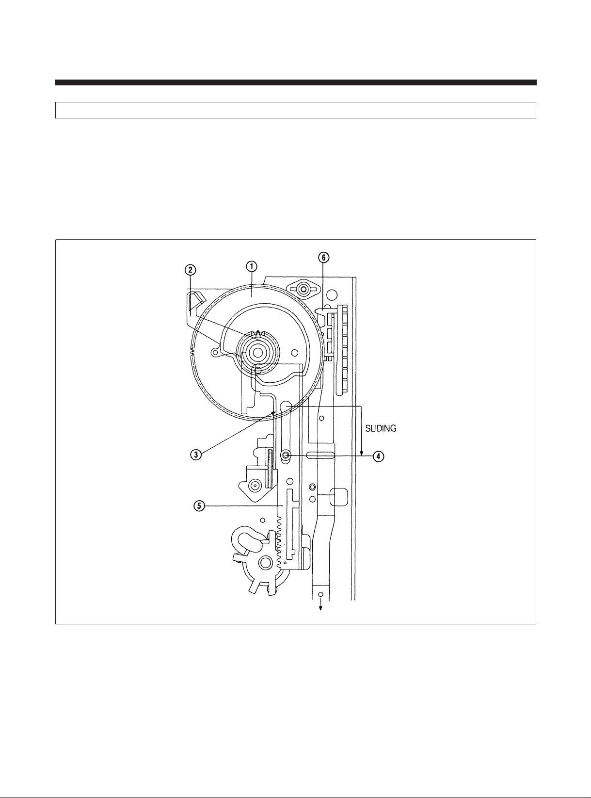
8. REPLACEMENT OF THE CAM GEAR, RELA Y PLATE, F/L RACK
1) Remove the RELAY GEAR according to the SEC. 3-7.
2) Remove the PINCH LEVER TOTAL ASS?Y and L/C BRAKT ASS?Y according to SEC. 3-4 and 3-7.
3) Remove the CAM GEAR ! .
4) Remove the RETURN LEVER @ .
5) Slide the RELAY PLATE % until the HOLE # formed in RELAY PLATE meets the PINCH POST $ and disassemble
the RELAY PLATE.
6) Slide the F/L RACK ^ in the direction of arrow and then remove the F/L RACK backward.
7) After changing new components, assemble it in reverse order.
8) Pay attention to the location of assembling when re-assemble. (See Fig. 4-1)
(See Fig. 3-7)
Fig. 3-7
28
Page 30
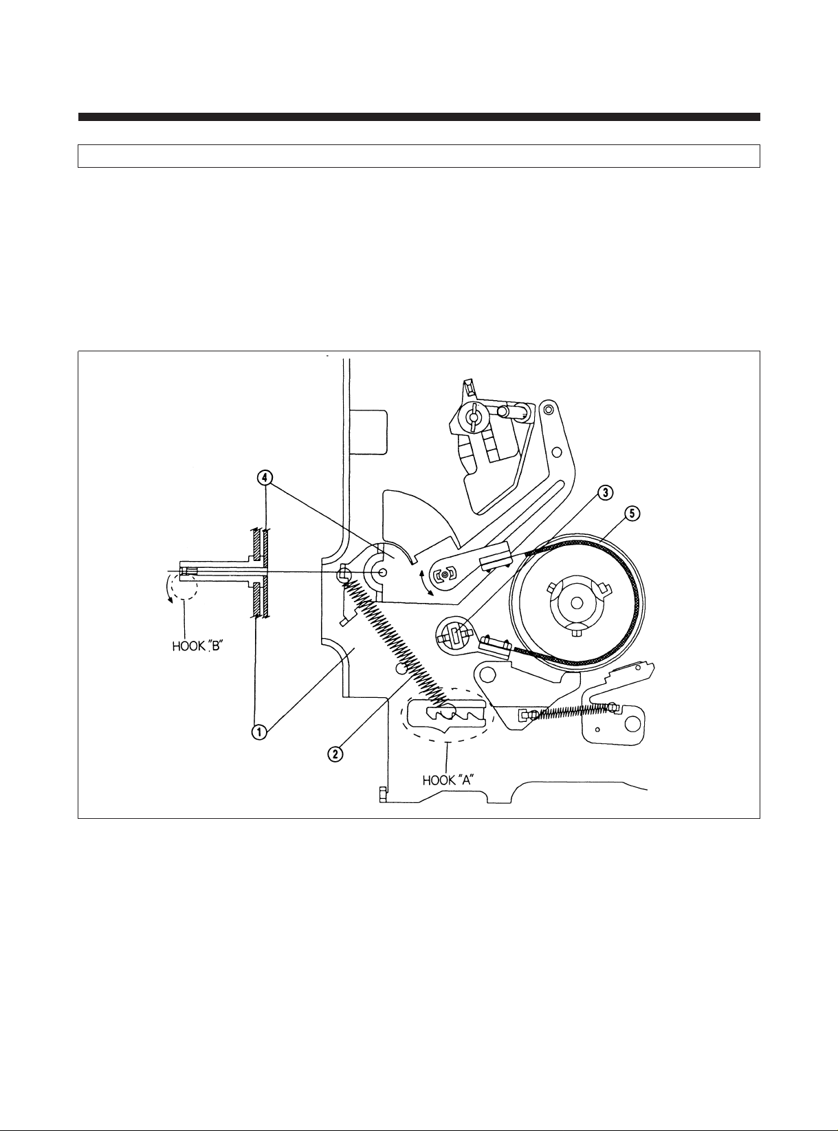
9. REPLACEMENT OF THE TENSION LEVER ASS?Y
1) Separate the TENSION SPRING @ from the HOOK "A" of the MAIN BASE ! .
2) Remove the BAND BRAKE CAP # by means of lift with proper force.
3) Disassemble the TENSION LEVER ASS?Y $ in the state of pulling back the HOOK "B".
4) Remove the BAND BRAKE ASS?Y % from the TENSION LEVER ASS?Y while rotating in the direcction of the arrow.
5) Re-assemble in the reverse order.
6) After re-assembling it, adjust the position of the TENSION POLE. (See SEC. 4-4)
7) If necessary, adjust and measure the BACK TENSION (See SEC. 4-5).
8) Avoid getting grease or oil on the FELT of the BAND BRAKE ASS?Y.
Also avoid damaging the HOOK "B".
(See Fig. 3-8)
Fig. 3-8
29
Page 31
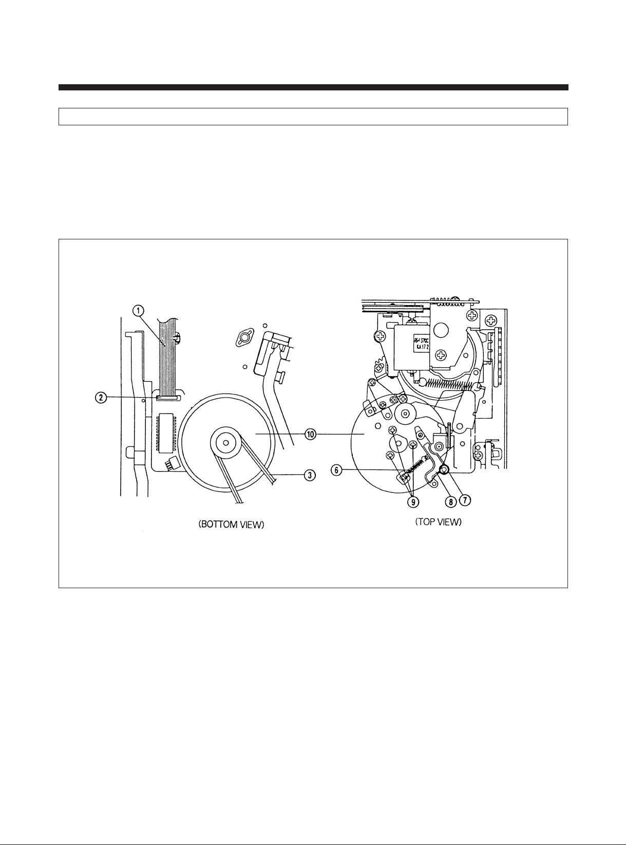
10. REPLACEMENT OF THE CAPST AN MOTOR (See Fig. 3-9)
1) After turning over the DECK ASS?Y, separate the CAPSTAN FFC ! from the CONNECTOR @ .
2) Disassemle the REEL BELT # .
3) Separate the CAPSTAN BRAKE SPRING $ from the HOOK "A".
4) Disassemble the CAPSTAN BRAKE ASS?Y % in the state of pulling back the HOOK "B".
5) After turning over the DECK ASS?Y again, separate the REVIEW ARM SPRING ^ from the HOOK "C".
6) After removing the POLY WASHER & , disassemble REVIEW ARM ASS?Y * .
7) After removing the 3 screws ( from the CAPSTAN MOTOR, disassemble the CAPSTAN MOTOR ) .
Fig. 3-9
30
Page 32

4. MECHANICAL ADJUSTMENTS
1. MECHANICAL CHECKS
If irregular operation occurs or when reassembling a part, please check the following.
1) Make sure that the datum hole of the RELAY PLATE meets that of the MAIN BASE in the Eject Mode as shown in Fig.
4-1.
2) Make sure that the datum hole of the CAM GEAR meets that of the MAIN BASE in the Eject Mode as shown in Fig. 4-1.
3) There are two triangle mark in the MODE SWITCH. When installing the L/C BRKT ASS'Y, make sure that the one marks
meets the other in the Eject Mode as shown in Fig. 4-2.
4) Make sure the that the BOSS of the PINCH LEVER ASS'Y is located outside of the CAM of the CAM GEAR in the Eject
Mode as shown in Fig. 4-2.
5) Make sure that the datum hole of the MAIN PLATE meets that of the MAIN BASE in the Eject Mode as shown in Fig. 4-
3.
6) When installing the RELAY GEAR, make sure that the triangle mark meets the last groove of the teeth of the MAIN
PLATE in the Eject Mode as shown in Fig. 4-3.
7) Make Sure that the triangle mark of the L LOADING GEAR ASS'Y meets the -Shaped mark of the R LOADING GEAR
ASS'Y in the Eject Mode as shown in Fig. 4-4.
8) Make sure that the 1'st tooth of the R LOADING GEAR ASS'Y meets the 1'st groove of the LOADING GEAR ASS'Y in
the Eject Mode as shown in Fig. 4-4.
31
Page 33
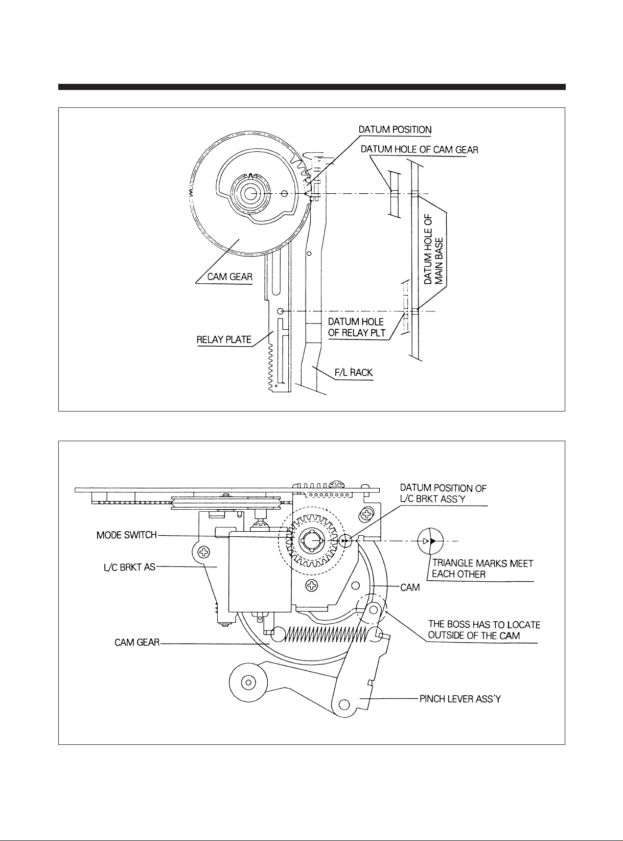
Fig. 4-1 DATUM POSITION OF RELAY PLATE & CAM GEAR
Fig. 4-2 DATUM POSITION OF L/C BRKT AS & PINCH LEVER AS
32
Page 34
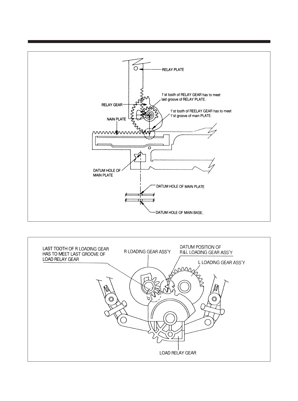
Fig. 4-3 DATUM POSITION OF MAIN PLATE & RELAY GEAR
Fig. 4-4 DATUM POSITION OF LOADING GEAR ASS?Y & LOAD RELAY GEAR
33
Page 35
2. HOW TO SET MECHANICAL MODE
1) With the F/L ASS?Y removed, turn on the POWER.
2) If rotate the WORM PULLEY 2 or 3 times manually, it will start loading and move to PLAY/STOP mode.
3) Press the desired button.
4) On performing the desired mode, pull out the power plug from the outlet.
5) Assemble and disassemble the F/L ASS?Y in the only EJECT mode.
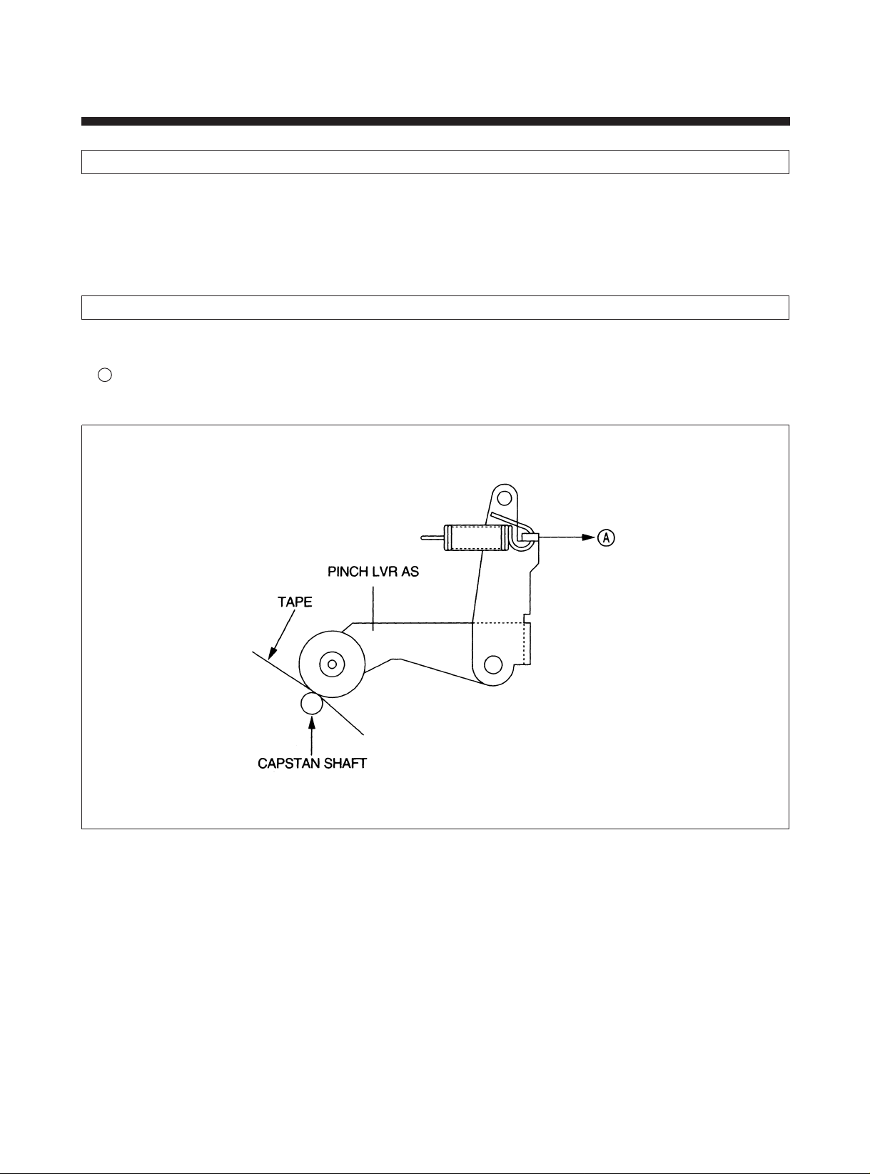
3. MEASUREMENT OF PRESSING FORCE FOR PINCH ROLLER
1) In the state of loading the cassette tape, playback the tape by pressing the PLAY button.
2) After hanging the PUSH-PULL GUAGE on the HOOK of PINCH LEVER TOTAL AS, pulling it to the direction of
A
indicated by the arrow as shown Fig. 4-5.
3) The very moment tape stop, read the scale of PUSH-PULL GUAGE. (SPEC: 1.1±0.2 kg).
Fig. 4-5 MEASUREMENT OF PRESSING FORCE FOR PINCH ROLLER
34
Page 36
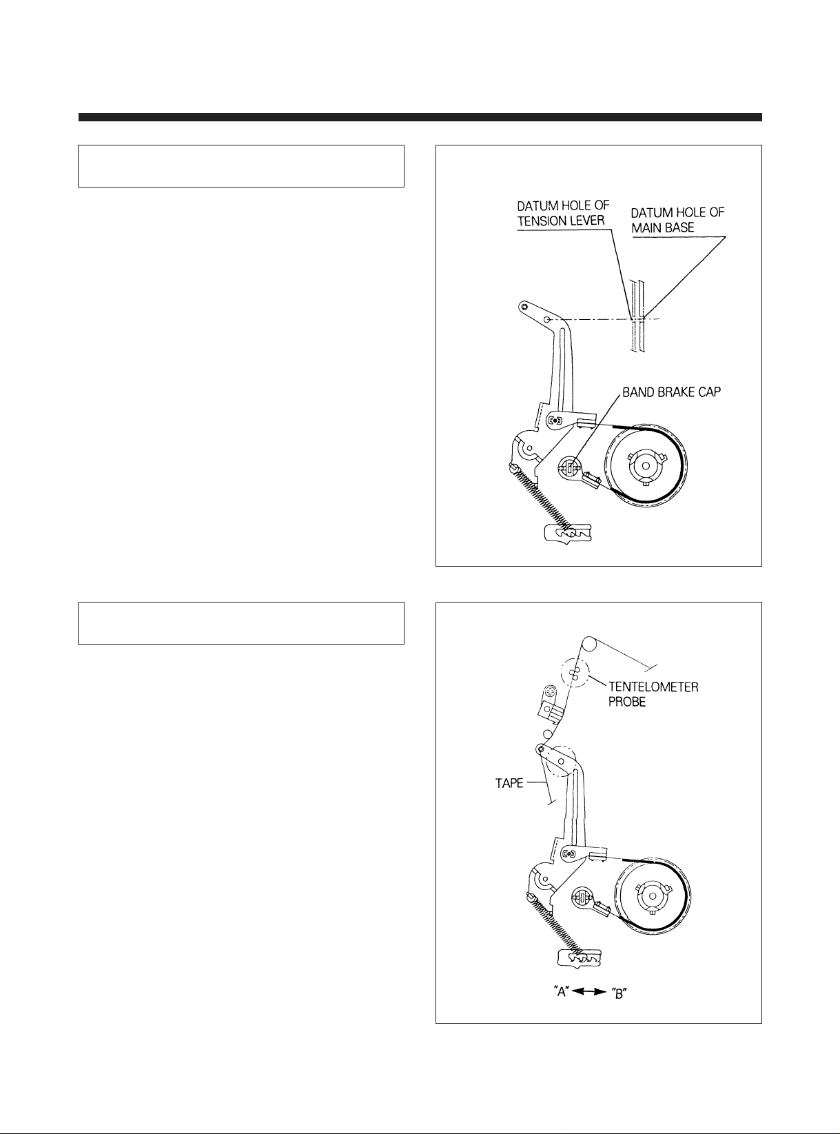
4. ADJUSTMENT OF TENSION
POLE POSITION
1) Turn on the Power and set to PLAY Mode by turning
the WORM WHEEL without cassette.
2) Confirm with your eyes whether the datum hole of
TENSION LEVEL meets that of the MAIN BASE.
3) If they do not meet, turn the BAND BRAKE CAP to the
CW or the CCW direction until holes meet each other
(See Fig. 4-6).
5. MEASUREMENT OF THE
BACK TENSION
1) Before mesuring the BACK TENSION, make sure that
the position of TENSION POLE is adjusted correctly.
2) Play back T-120 tape at its center position without F/L
ASS?Y, wait until the tape running is stabilized (about
10-20 seconds).
3) Set the Tentelometer as shown in Fig. 4-7 and confirm
the scale (SPEC: 20-27 gr/cm).
4) If the scale indicates more than 27 gr/cm, move the
TENSION SPRING to "A" direction and less than 20 gr/
cm, move to "B" direction. (See Fig. 4-7)
NOTES:
• Make sure that the three probes of the TENTELO-
METER as all in good contact with tape.
• It is recomended to be measured three times as
TENTELOMETER is very sensitive.
Fig. 4-6 ADJUSTMENT OF THE TENTION POLE POSITION
35
Fig. 4-7 MEASUREMENT OF THE BACK TENTION
Page 37
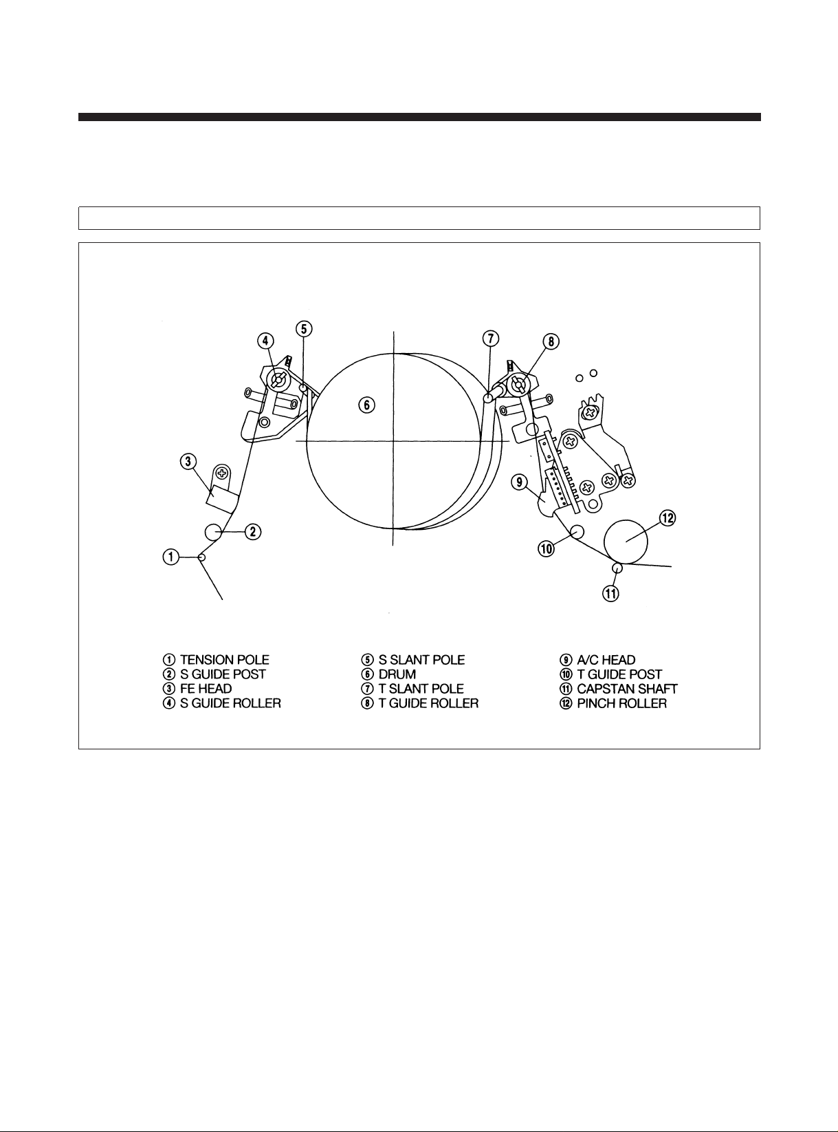
5. THE ADJUSTMENT OF THE TAPE
TRANSPORTING SYSTEM
The tape transporting system has been precisely adjusted at the factory and does not ordinary require readjustment. But
when the noise and tape damage takes place and parts that compose the tape transporting system are replaced due to
troubles by long usage or unexpected accidents, check and readjust the tape transporting system.
5-1. THE SCHEMA TIC DIAGRAM OF TAPE TRANSPORTING SYSTEM
Fig. 5-1
36
Page 38
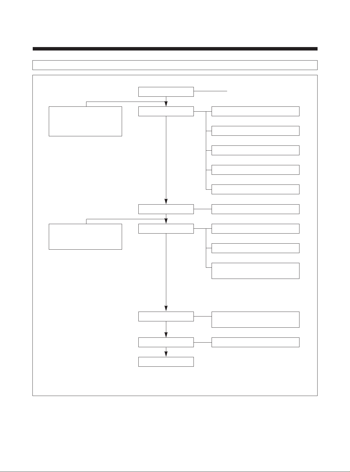
2. ADJUSTMENT FLOW
CHANGE
• DRUM TOTAL ASS'Y
• A/C HEAD ASS'Y
• PINCH LEVER TOTAL
ASS'Y
CHANGE
• S-POLE BASE ASS'Y
• T-POLE BASE ASS'Y
• TENSION LEVER ASS'Y
CLEANING
PATH ROUGH ADJ.
PATH PRE-ADJ.
LINEARITY ADJ.
SEC. 2-2
S GUIDE ROLLER HEIGHT ADJ.
S GUIDE POST FLANGE
T GUIDE ROLLER HEIGHT ADJ.
A/C HEAD TILT
A/C HEAD HEIGHT ADJ.
(PG)
ENTERANCE ENVELOPE
EXIT ENVELOPE WAVEFORM
ADJ
.
AUDIO ADJ.
X-POSITION ADJ.
TRACKING
ENTERANCE & EXIT ENVELOPE
WAVEFORM FINE ADJ.
• X-POSITION ROUGH ADJ.
• ENTERANCE & EXIT ENVELOPE
WAVEFORM FINE ADJ.
• REVIEW ¡ŒPLAY
AUDIO TILT, HEIGHT
AZIMUTH ADJ
SP, EP
37
Page 39

3. REPLACEMENT OF THE S, T SLANT POLE ASS?Y
1) Remove the DRUM TOTAL ASS?Y according to the method of the SEC. 3-2.
2) Remove the 2 screws ! and the LOADING GUIDE PLATE @ .
3) Remove the R & L LOADING GEAR ASS?Y # , $ .
4) Remove the S & T SLANT POLE ASS?Y % , ^ after moving them to the point "A" by pulling them in the direction of the
arrow ¨O.
5) After changing new SLANT POLE ASS?Y please assemble it in the reverse order.
6) Be careful not to get grease on the GUIDE ROLLER.
(See Fig. 3-3)
Fig. 3-3
38
Page 40
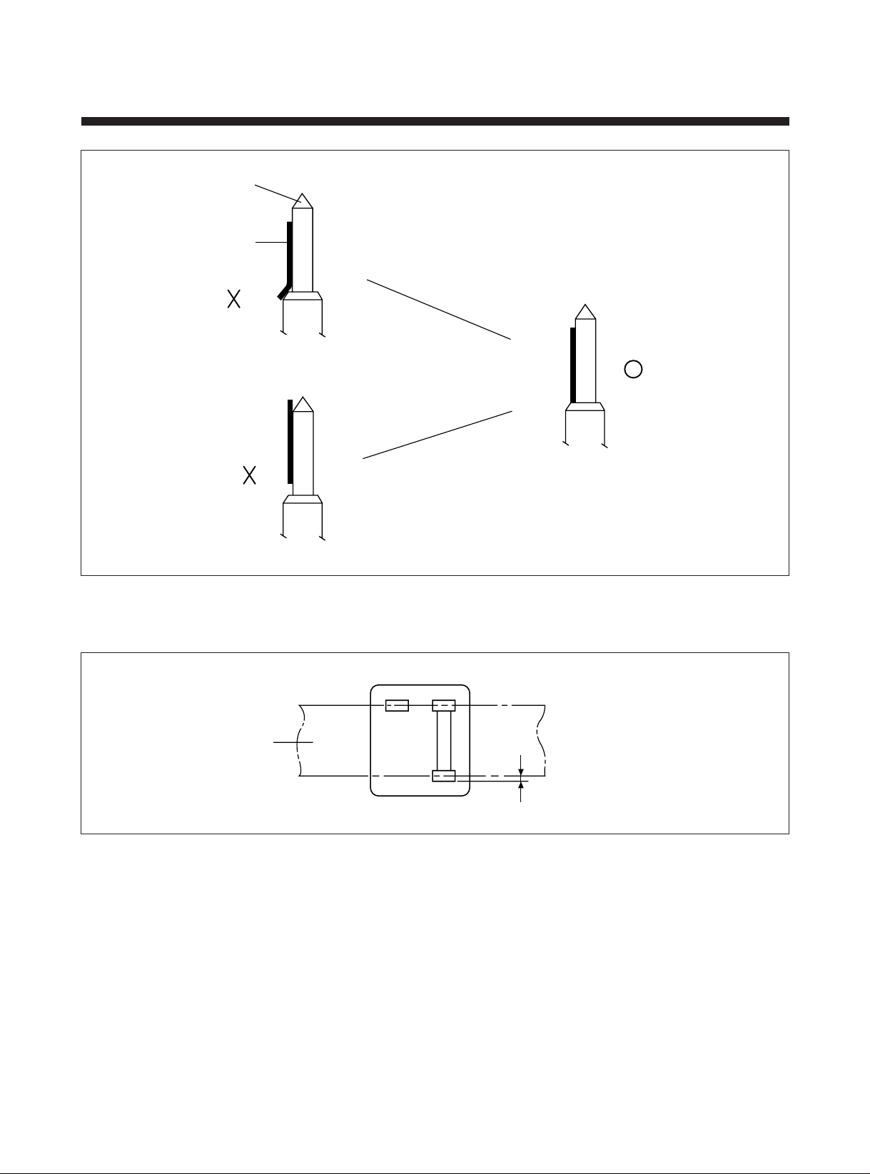
TAPE
GAP
= 0.5 mm
T GUIDE POST
TAPE
Turn the TILT SCREW @
to the direction of CCW.
1-3) THE HEIGHT ADJUSTMENT OF A/C HEAD
Turn the TILT SCREW @
to the direction of CW.
Fig. 5-3
Fig. 5-4
A. Make sure that the gap is 0.5mm between the lower end of tape and that of CTL HEAD.
B. Turn and adjust the screw to CCW in order !¡@¡#when the gap is longer than 0.5mm.
C. Turn and adjust the screw to CW in order !¡@¡#when the gap is shorter than 0.5mm.
39
Page 41
2) PLAYBACK PHASE ADJUSTMENT (PG ADJUSTMENT)
6.5H ± 0.5H
CH 1
CH 2
ab
A. Connect the CH 1 of OSCILLOSCOPE to the TP 01-3 (HEAD SWITCHING PULSE) and connect the CH 2 to the VIDEO
OUT and adjust the TRACKING VR to the center.
B. Play back the STAIR STEP SIGNAL TAPE (DP-2).
C. Adjust the PG VOLUME for time interval of 6.5H ± 0.5H between switching pulse and V-sync signal.
Fig. 5-5
3) LINEARITY ADJUSTMENT
Connect the CH1 of the OSCILLOSCOPE to the TP01-2 (CTL PULSE).
CH2 to the TP01-4 (ENVELOPE WAVEFORM) and EXT. TRIGGER to the TP01-3 (SWITCHING PULSE) and play back the
TEST TAPE in SP mode.
3-1) AJUSTMENT OF THE S, T GUIDE ROLLER
A. Adjust the TRACKING VR to obtain maximum FM SIGNAL of the TEST TAPE.
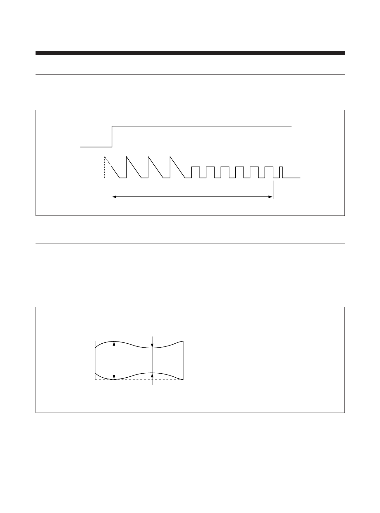
B. Adjust the S, T GUIDE ROLLER (refer to Fig. 5-1 $ , * ) until the ENVELOPE waveform at the entrance and the exit
sides is as shown in Fig. 5-6.
a: MAX. OUTPUT OF ENVELOPE
b: MIN. OUTPUT OF ENVELOPE
b/a ¡ˆ0.75
Fig. 5-6
40
Page 42
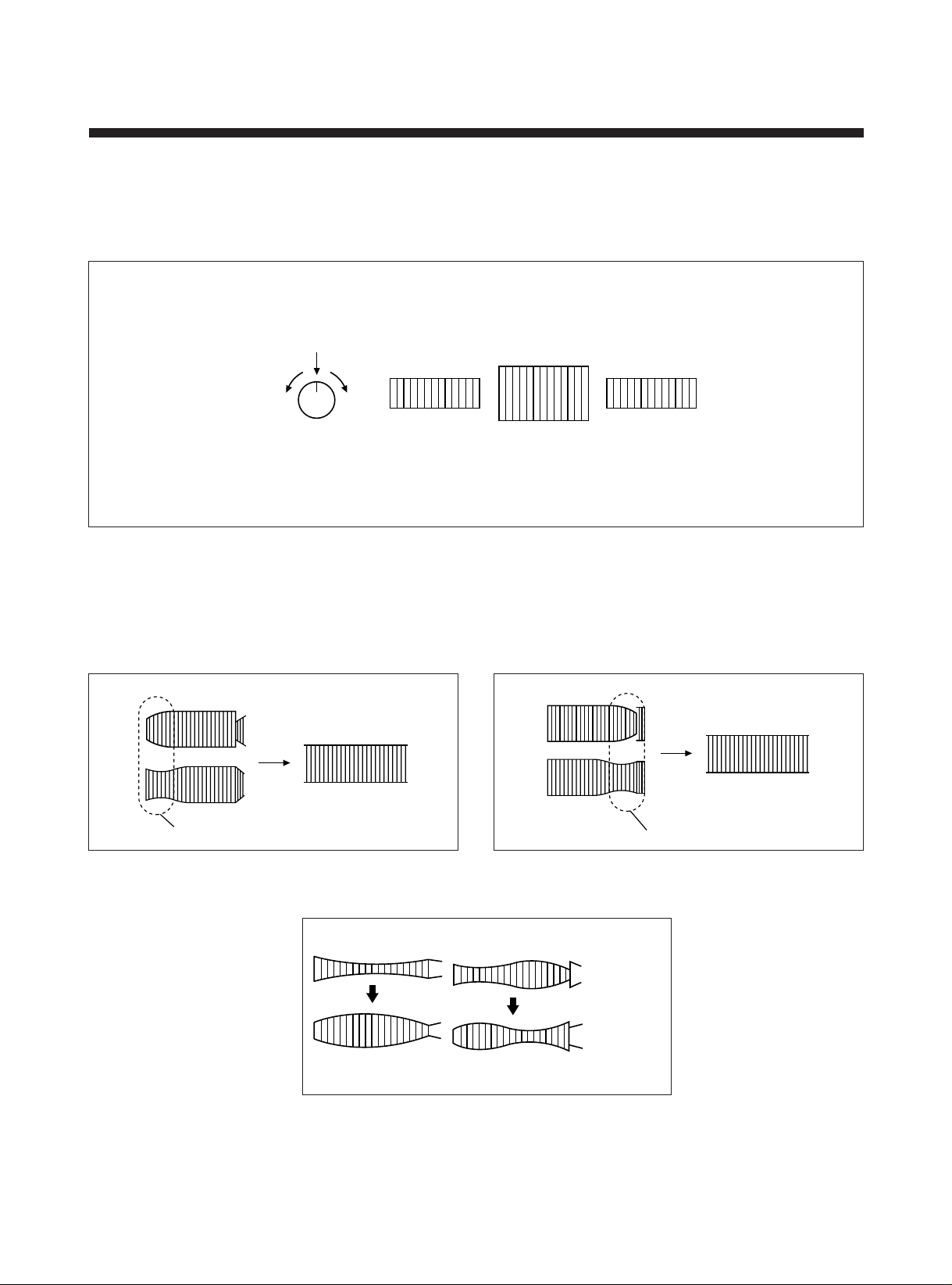
3-2) ROUGH ADJUSTMENT OF THE X-POSITION
CENTER
CCW CW
TRACKING
CCW
TRACKING
CENTER
TRACKING
CW
A. Turn the TRACKING VR to center.
B. Release the $ , % screw of the AC HEAD in Fig.5-2 about 90-120 degrees.
C. Turn the AC HEAD TOT AS to obtain maximum ENVELOPE waveform by using the (–) driver as shown in Fig. 5-2.
Fig. 5-7
3-3) THE FINE ADJUSTMENT OF THE ENTRANCE AND THE EXIT SIDES OF ENVELOPE WAVEFORM
A. Turn the TRACKING VR to CW or CCW and check the ENVELOPE waveform is changed uniformly.
B. If the ENVELOPE waveform as shown in Fig.5-8, 9, 10 is not uniformed, adjust the S, T GUIDE ROLLER repeatedly at
the point of nonflat.
DRUM INPUT DRUM OUTPUT
Fig. 5-8 Fig. 5-9
Fig. 5-10
41
Page 43
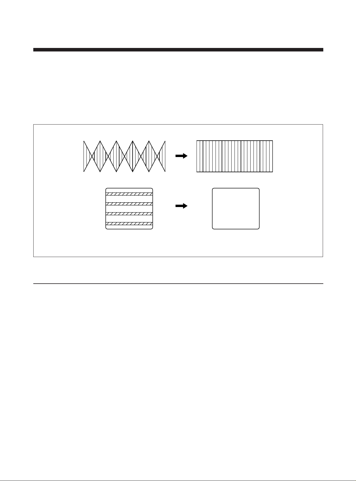
3-4) CHECK FOR TRANSITIONAL OPERATION FROM REVIEW WAVEFORM TO PLAY WAVEFORM
REVIEW PLAY
A. Play back DP-2 test tape (Recorded Stairstep signal in SP mode).
B. Make sure the ENVELOPE waveform is maximum.
C. Review the tape and push the PLAY BUTTON after 5 seconds at least.
Check whether the ENVELOPE waveform is returned to the normal PLAY waveform or not within 3 seconds and there
is any noise at the upper and lower side of monitor.
D. In case return of the ENVELOPE waveform at the entrance and the exit sides is slow or the noise is occurred at the
upper or lower side of monitor, check the running state of tape at the lower end of T GUIDE POST. If the tape is
creased, re-adjust the S, T GUIDE ROLLER.
ENVELOPE
WAVEFORM.
MONITOR
Fig. 5-11
4) AUDIO ADJUSTMENT
Make sure no tape wrinkle is caused at the lower end of T GUIDE POST during play and if not, perform the audio
adjustment.
4-1) ADJUSTMENT OF THE AUDIO TILT AND HEIGHT
A. Connect the AUDIO OUTPUT to the AUDIO LEVEL METER.
B. Play back the DP-1 (COLOR BAR) and check the level of the AUDIO OUTPUT.
SPEC.: MIN. OUTPUT –4.5~–8.5dBm.
C. In case the output of 1KHz is out of the specification, re-adjust the TILT and the HEIGHT of AC HEAD at the same
method as 1-2) and 1-3).
42
Page 44
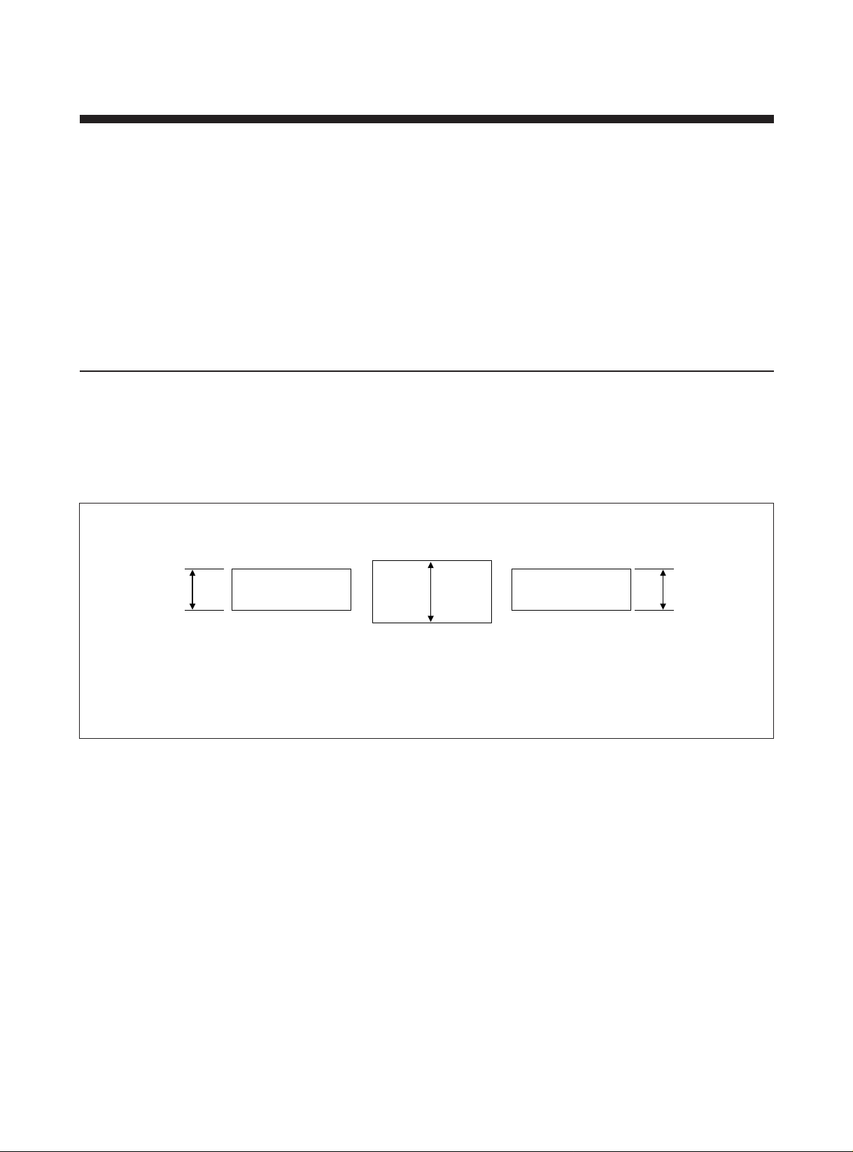
4-2) AUDIO AZIMUTH ADJUSTMENT
A CB
CH A (R HEAD)
TRACKING CCW 10ms
CH A (R HEAD)
TRACKING CENTER
CH A (R HEAD)
TRACKING CW 10ms
A. In state of the connecting AUDIO OUTPUT to AUDIO LEVEL METER, play back the DP-2 tape (STAIRSTEP: 6KHz).
B. Adjust the AUDIO output to be maximum by turning of AC HEAD AZIMUTH SCREW (refer to Fig. 5-2 # ).
SPEC.: MIN OUTPUT: –8.5~–12.5DBM
THE DIFFERENCE BETWEEN 1KHz AND 6KHz: +2~–4dBm
THE RANGE OF CHANGE OF AUDIO LEVEL IN 6KHz: less than 1dBm.
C. After adjusting, check whether the tape is shaked or flickered during running in between T GUIDE ROLLER and AC
HEAD.
If the problem is occurred, re-adjust the AUDIO.
D. After adjusting, reconfirm the ENVELOPE waveform.
If the problem is occurred, perform the fine adjustment of the entrance and the exit sides of ENVELOPE WAVEFORM at
the article 3-3) method.
5) X-POSITION ADJUSTMENT
A. Connect CH 1 of the OSCILLOSCOPE with TP01-2 (CTL PULSE), CH2 with TP01-4 (ENVELOPE) and EXIT. TRIGGER
with TP01-3 (SWITCHING PULSE).
B. After tuning the TRACKING VR to center, play back the TEST TAPE (SP MODE).
C. Turn the AC HEAD TOT AS by using (–) driver in the same method as Fig. 5-2 in order that the ENVELOPE waveform is
as shown in Fig. 5-12 when the TRACKING VR is turned to CW or CCW.
D. After adjust the X-POSITION, please confirm the PG.
A ¡ C
Fig. 5-12
43
Page 45
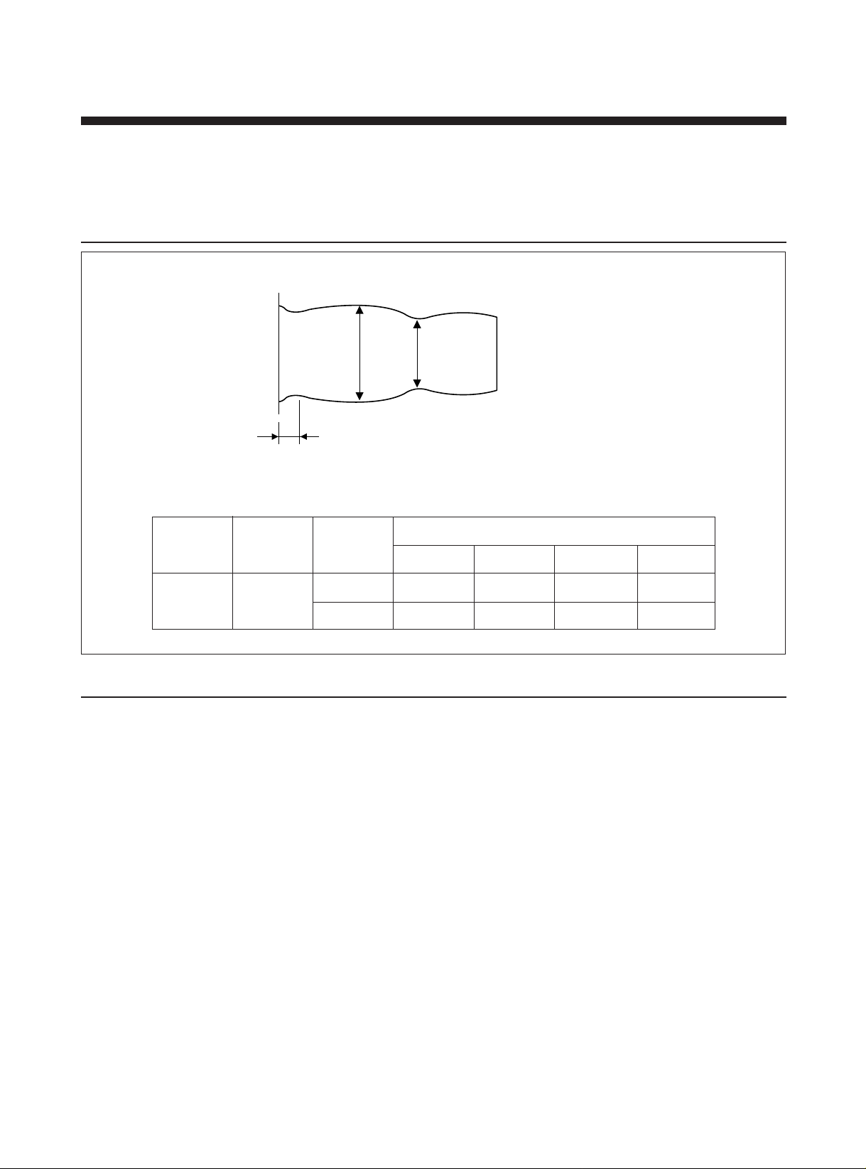
D. If not, re-adjust from the article B.
ab
E. After adjusting X-POSITION, check whether 6KHz output of DP-2 is maximum.
F. When the adjustment is completed, fasten the AC HEAD SCREW $ , % suitably.
6) CHECK FOR THE LINEARITY OF CO-EXCHANGING TRACKING
a : MAX
b : MIN
Vert = b/a
(FM)
MODE TAPE CHECK
CCW 6ms CCW 4ms CENTER CW 6ms
LINEARITY 4 : 3 4 : 3.5 4 : 3
SP DP-2
NOISE NOTHING NOTHING NOTHING
7) FINAL CHECK
Make sure no tape wrinkle is caused at each GUIDER ROLLER and POST.
TRACKING VR
44
Page 46
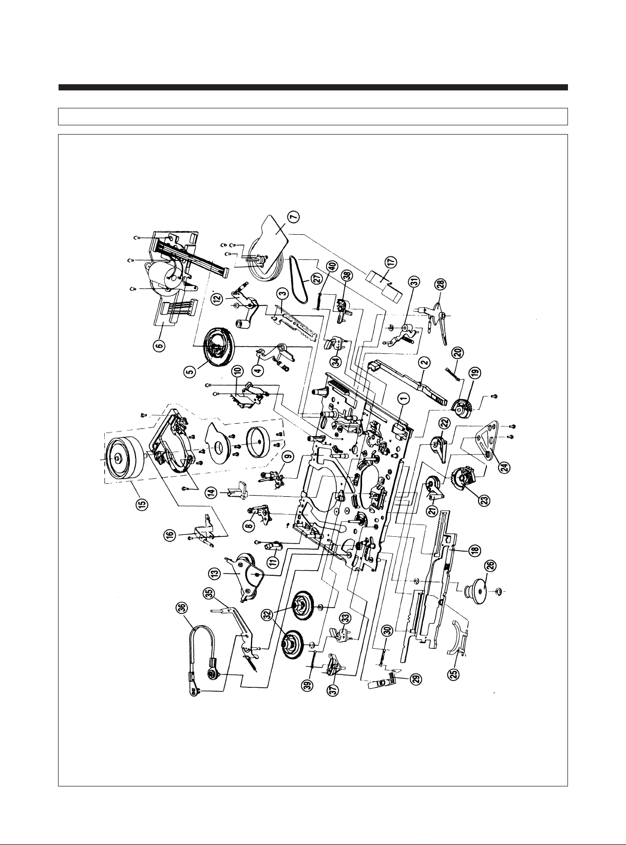
6. EXPLODED VIEW AND PARTS LIST
1. EXPLODED VIEW OF DECK ASS'Y
45
Page 47
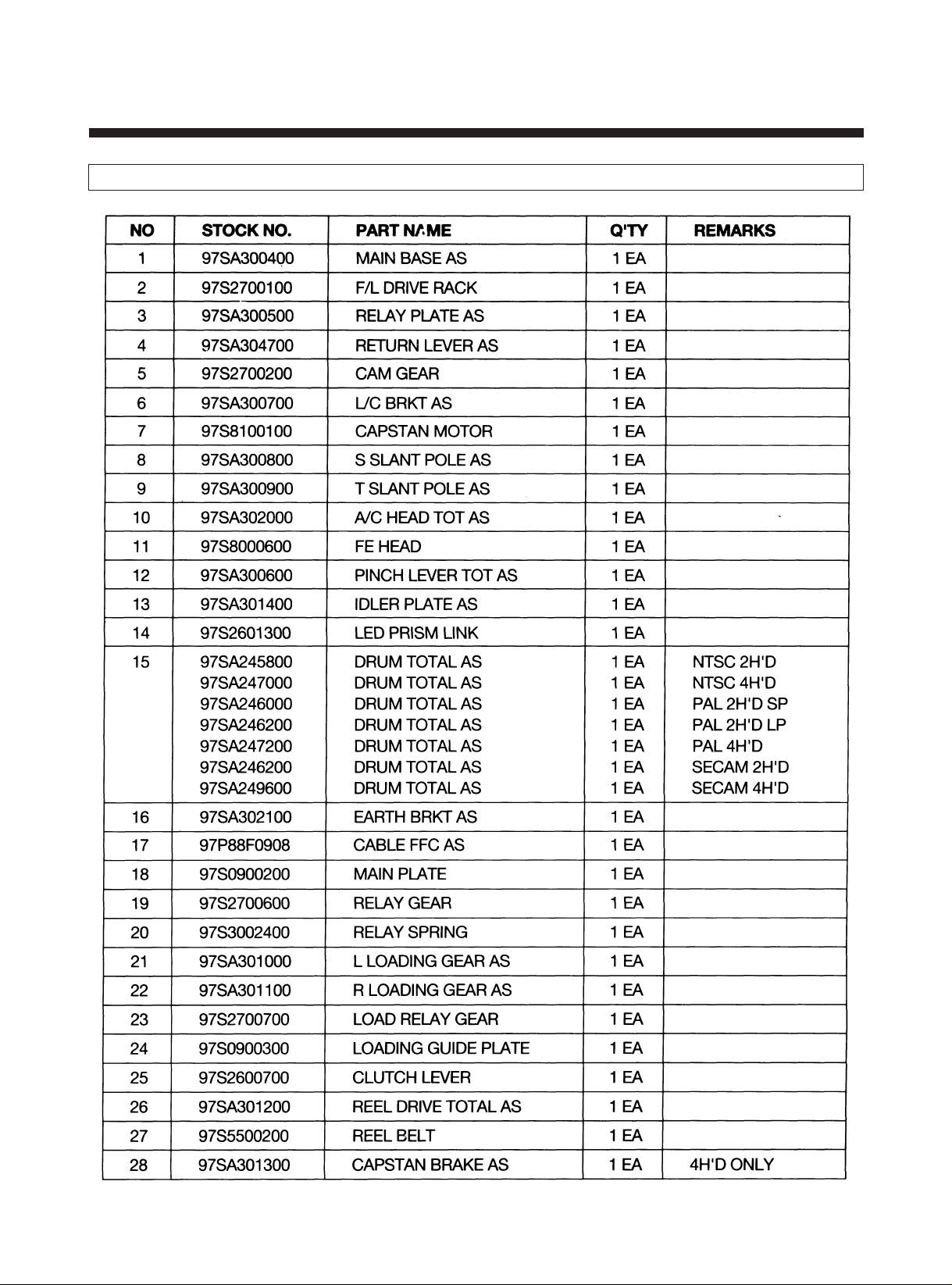
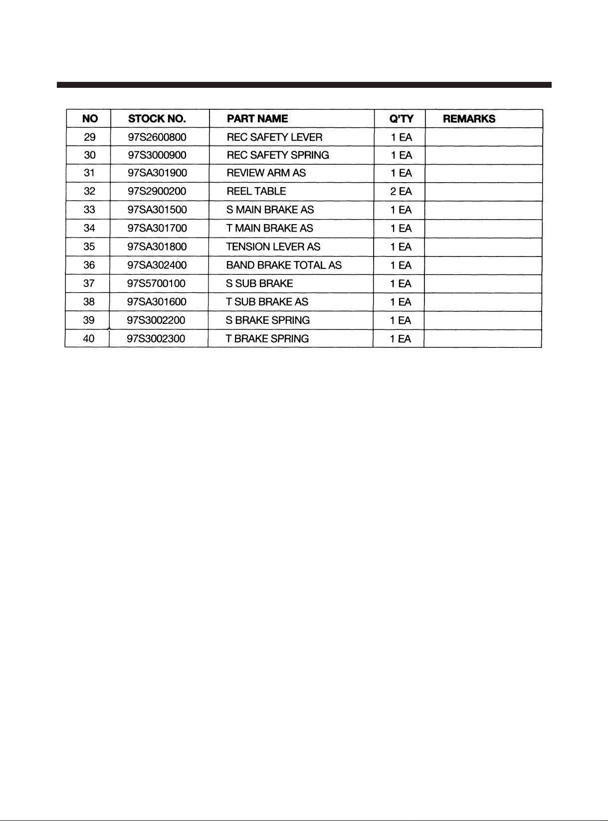
2. PARTS LIST OF DECK ASS'Y
46
Page 48
47
Page 49
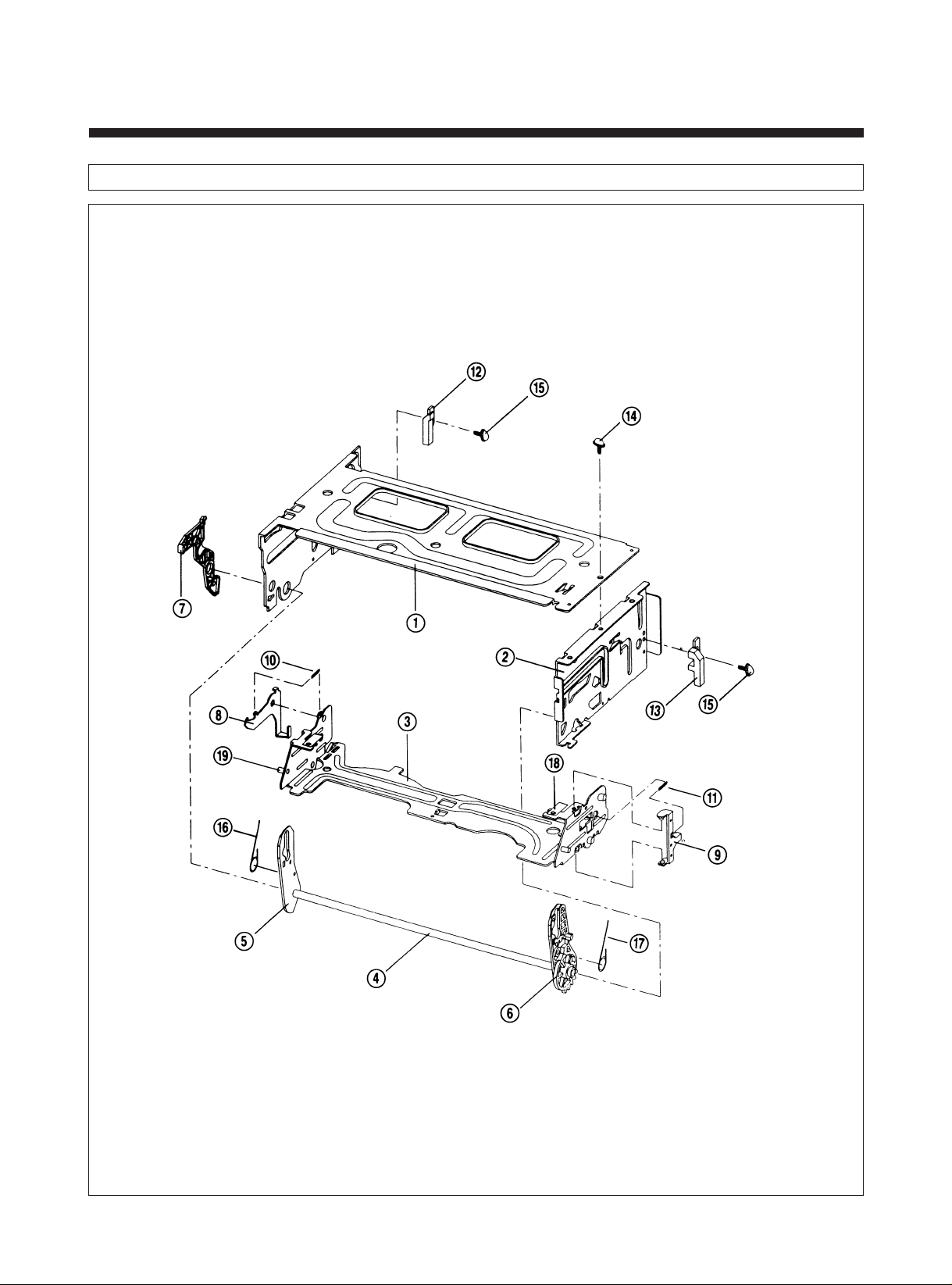
3. EXPLODED VIEW OF F/L ASS'Y
48
Page 50
4. PARTS LIST OF F/L ASS'Y
49
Page 51
5. MAIN SPARE PARTS LIST OF DECK ASS'Y
50
Page 52
51
 Loading...