

Page 1

1
CONTENTS
1. SPECIFICATION
.......................................................................
2
2. DIAGRAM
..................................................................................
3
1) WIRING DIAGRAM
................................................................
3
2) CIRCUIT DIAGRAM
..............................................................
3
3. CAUSE OF TROUBLE AND COUNTERMEASURE
................
4
4. COUNTERMEASURE DETAIL
.................................................
5
5. EXPLODED VIEW AND PARTS LIST
......................................
9
1) BODY ASSEMBLY
................................................................
9
2) COVER ASSEMBLY
...........................................................
11
3) HOSE LINE ASSEMBLY
.....................................................
13
4) BRUSH ASSEMBLY
............................................................
15
Page 2

1. SPECIFICATION
2
RATING 220V, 50~60Hz
INPUT 1010W
AIR WATT 330W
VACUUM 1,050 mmAq.
AIR FLOW 1.11 m/min.
NOISE 65 dB
DIMENSION (L X H X W) 356 X 221 X 246mm
POWER CORD RETRACTABLE 5m
SUCTION CONTROL ELECTRIC SLIDE
DUST METER MECHANICAL
PARTS KEEPING STAND KEEPING
DUST BAG CAPACITY 2.2 Liter
POWER SWITCH ON HOSE HANDLE
FUSE RATING 250V, 6A
WEIGHT
BODY 3.8Kg
NET 4.9Kg
DUST CAVITY
2-LAYER PAPER BAG
FILTER
NON-WOVEN FABRIC MAT
MOTOR CAVITY NON-WOVEN FABRIC MAT
HOSE CURRENT 1.3m
EXTENTION PIPE PLASTIC 2 EA
BRUSH CLEAN
SPARE PAPER BAG 2 EA
Page 3
2. DIAGRAM
3
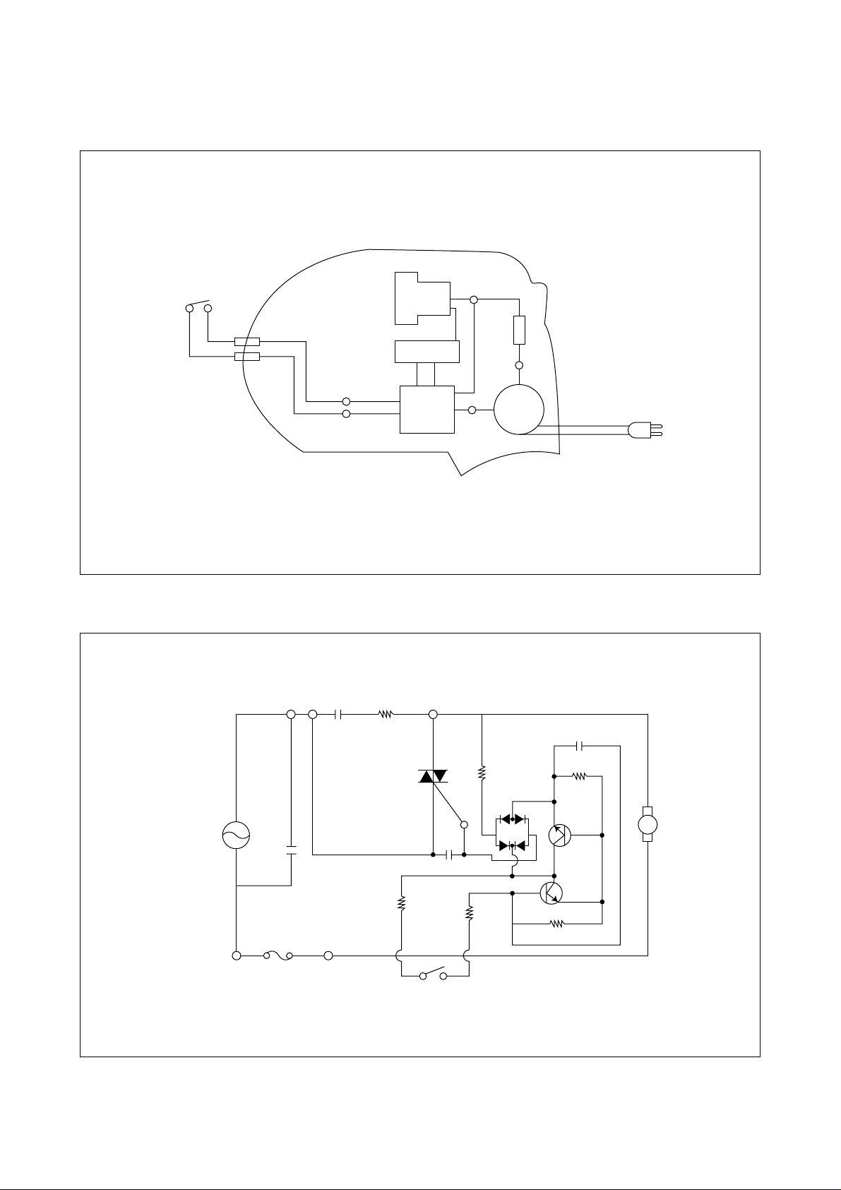
1) WIRING DIAGRAM
BK
RED
ORANGE
BK
MOTOR
BL
FILTER COIL
SWITCH
YL
YL
P.C.B
CORD
REEL
WH
FUSE
2) CIRCUIT DIAGRAM
220V
50~60Hz
C1
FUSE
220V, 6A
R5
R6
S/W
R4
Q2
Q1
M
R3
R2
C3
DIODE
T2
T1
TRIAC
R1C2
C4
Page 4

3. CAUSE OF TROUBLE AND COUNTERMEASURE
4
TROUBLE
Motor does not
rotate.
Motor does not
stop even if the
switch is set
"OFF".
Suction power
is low.
Dust is
excessively
discharged from
exhaust grill
during operation.
Cord can not be
wound up.
Cord does not
stop at arbitrary
position.
CHECK POINT
Power cord
Fuse
Terminal in body
Cord reel
Motor
Hose switch
Connections
PCB assembly
Hose switch
PCB assembly
Paper bag
Hose, brush, and
pipe
Filter
Motor
Paper bag and
filter
Cord reel
Power cord
Reserved winding
Tire
Bobbin
CAUSE
Break of power cord (at
blade tip or root of plug)
Fuse cut-out
Deflection or break in
connections
Deflection of terminal or
break in connections
Abrasion of carbon brushes
Break in motor winding
Deflection of terminal
Break
Defective TRIAC
Deflection of terminal
Defective TRIAC
Full bag with dust
Blocked or break
Clogged
Defective Motor
Damaged or torn
Break of the spring for
winding cord.
Entanglement of cord
Insufficient reserved
winding
Abrasion of the tire
Sticking dust on the surface
of the bobbin
COUNTERMEASURE
Replace the power cord.
Replace the fuse. (Detail 1)
Repair. (Detail 2)
Repair. (Detail 3)
Replace the carbon brushes. (Detail 4)
Replace the motor.
Repair.
Repair. (solder or use connectors)
Replace the PCB assembly.
Repair.
Replace the PCB assembly.
Replace the paper bag. (CP-11)
Remove the obstacle or replace.
Clean the filter.
Replace the motor.
Replace the paper bag or the filter.
Replace the bobbin assembly.
Draw out the cord 40-50 Cm and wind
up again.
Add proper reserved winding. (6 turns)
Replace the tire.
Clean.
Page 5
4. COUNTERMEASURE DETAIL
5
COUNTERMEASURE COUNTERMEASURE PROCEDURE
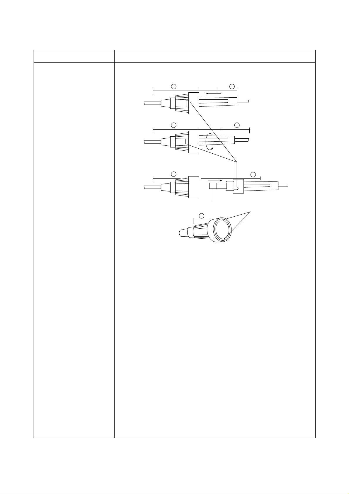
1. Replacing a fuse
1. Remove 3 screws (41) of the bottom of the body (1), so the
cover assembly can be separated from the body.
2. Take out the fuse assembly from the body.
3. Rotate B part with pushing in the directions as shown the above
figure.
4. Separate B part from A part, and then replace the fuse (250V,
6A)
5. When assembling, rotate B part in the opposite direction of
separating after inserting the projection of the B part into the
groove of the A part.
*CAUTION
Take care not to damage the internal wires on assembling.
A B
A
A
Fuse
A
B
Projection
B
Groove
Page 6
6
COUNTERMEASURE COUNTERMEASURE PROCEDURE
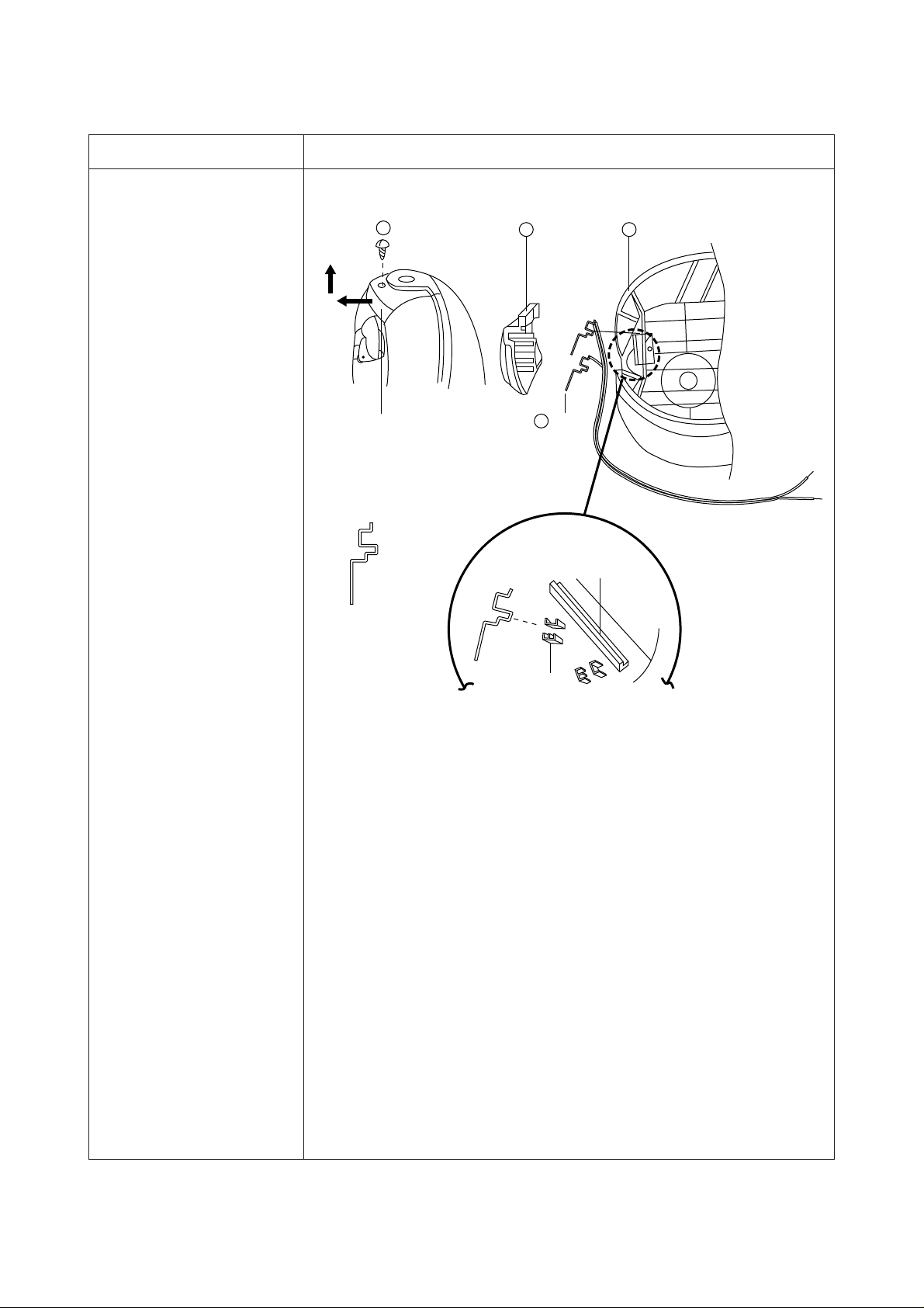
2. Repairing the terminal
in the body
1. After removing the screw (4), pull out the frame in the directions
as shown the above figure from the body.
2. Check the terminals (3).
-They are bent or deflected other than standard shape. ➪➪
Repair the terminals as shown the standard shape in the
above figure.
-Break of a wire. ➪ ➪ Soldering.
3. When assembling, first of all, fix the terminals into the grooves
of the body, and then push the frame top down, so the upper
part of the frame can be hung on the frame supporter of the
body.
4
Groove for carrying
Standard shape
2 Frame
3 Terminal
1 Body
Frame supporter
Groove
Page 7

7
COUNTERMEASURE COUNTERMEASURE PROCEDURE
3. Repairing the cord
reel assembly
1. Separate the cover assembly, and then take out the cord reel
assembly from the body.
2. After removing the screws (1), separate the PCB assembly.
3. Rotate the bobbin 6 turns in the opposite direction indicated by
the arrow mark on the cover (12).
4. After removing the screw (3), separate the bobbin from the
bracket (4).
5. Check the state of the contacts between the terminals (5, 6, 17).
-Deflection or break of the terminals (5, 6). ➪➪Repairing or
replacing them.
6. When assembling, after putting the bobbin and the bracket
toqether with the screw (3), make a reserved wind of 6 turns.
*CAUTION
Take care not to separate the spring (13) from the cover (12).
It is very dangerous.
2 84 0 u y t r e w q9
1 5 6 3 7 i
Page 8

8
COUNTERMEASURE COUNTERMEASURE PROCEDURE
4. Replacing carbon
brushes
1. Separate the cover assembly, and then take out the motor from
the body.
2. Check whether the brush cap is separated from the brush
bolder.
-Separation of the brush cap. ➪ ➪ Fix it.
3. Check whether the carbon brush is worn out.
- In case that the length of the carbon brush is less than 5 mm.
➪
➪ Replace the carbon brush assembly in pair.
Motor
A
Brush cap
Brush holder
32mm
Carbon brush
5mm
Page 9

5. EXPLODED VIEW AND PARTS LIST
9
1) BODY ASSEMBLY (3620400800)
18
363534333231302928
40
38
2726252423222120
1091
171615
14
13
3 4242
19
11
12
250V 6A
5
41
6
7
8
37
✱
250V 8A
Page 10

PARTS LIST OF BODY ASSEMBLY
✱ REPLACEMENT PART LIST (Applied model: RC-209)
-BUTTON CR (4560F35020) ➞ BUTTON CR (3626601500)
10
NO. PART NAME PART CODE Q’TY DESCRIPTION
1 BODY 4560F20010 1 ABS
2 SOCKET 4560F20030 1 ABS
3 PACKING SOCKET 4560F20040 1 NATURAL RUBBER
4 TERMINAL 4565A37002 2 C5210P-EH
5 BRACKET ROLLER 4569C20041 1 PP
6 CASTER ROLLER 4568A54020 1 PP
7 LABEL 4560F10010 1 STICKER
8 ROLLER 4560F20020 2 PP
9 FUSE ASSEMBLY 4560A39002
1
250V, 8A
10 LABEL FUSE 4568F39010 1 STICKER
11 HOLDER FILTER 4560F25010 1 ABS
12 SPRING 4560F25080 1 HSW3
13 BAG FILTER 4560A57001 1 2-LAYER
14 FILTER 4560F24020 1 NON WOVEN FABRIC MAT
15 CAP MOTOR *F 4560M20101 1 NR
16 MOTOR UNIVERSAL 3962230200 1 220V, 1000W, O/S H
17 ABSORBER MOTOR 4569C10071 1 PU FORM
18 CAP MOTOR *L 3620900600 1 NR
19 GASKET COVER 4560F20060 1 PVC-S
20 SCREW TAPPING 7121400811 2 T2S PAN 4X8 MFZN
21 POWER CONTROL PCB AS 3624301101 1 RC-205 220V/60HZ
22 SCREW TAPPING 7121401211 1 T2S PAN 4X12 MFZN
23 BRACKET CR 4560F35010 1 ABS
24 SPRING 4560F35030 1 HSW3
25 BUTTON CR 3626601500 1 ABS(RC-209)
26 STOPPER CR 4569C35081 1 NBR
27 FRAME STOPPER 4565A35070 1 POLY ACETAL
28 TERMINAL 4565A36024 1 C2600P-1/2H
29 TERMINAL 4565A36034 1 C2600P-1/2H
30 HOLDER TERMINAL 4565A36010 1 ABS
31 BOBBIN 4565C35010 1 ABS
32 SCREW TAPPING 7121401211 1 T2S PAN 4X12 MFZN
33 SHAFT CR 4569C35051 1 PC LEAXAN 500
34 SPRING AS 3625102000 1 SUS301-EH-COVER,35
35 COVER 4565A35041 1 SPG
36 SCREW 7121300811 2 T2S PAN 3X8
37 TERMINAL AS 4560F42000 1 Y TERMINAL&LEAD
38 TERMINAL AS 4560F42000 1 Y TERMINAL&LEAD
39 CORD POWER 4560A38010 1 250V,7A
40 SCREW 7121400811 2 T2S PAN 4X8
41 SCREW 7121401411 3 T2S PAN 4X14
42 SCREW 7121301011 1 T2S PAN 3X10
✱
Page 11

11
2) COVER ASSEMBLY
16
8
15
9
10
11
12
13
14
7
6
4
3
2
1
5
✱
✱
✱
✱
Page 12

12
PARTS LIST OF COVER ASSEMBL Y
NO. PART NAME PART CODE Q’TY DESCRIPTION
1 COVER BODY 3621406600 1 ABS (RC-209)
2 FILTER 4560F24020 1 NON-WOVEN FABRIC MAT
3 PACKING 4560F24030 1 POLYETHILENE FOAM
4 COVER DUST 3621406700 1 ABS (RC-209)
5 HANDLE BODY 3622600300 1 ABS (RC-209)
6 BRUSH MULTI AS 4560A67000 1 ASSY
7 ELBOW DM 4560F23050 1 PVC-S
8 HOUSING DM 4560F23010 1 SAN
9 SPRING 3625100700 1 SUS
10 DUST METER 4560F23030 1 ABS GREEN
11 DUST METER 4560F23060 1 ABS RED
12 PACKING DM 3624000400 1 S-PVC
13 VALVE DM 3625400100 1 LDPE
14 SCREW TAPPING 7121300811 2 T2S PAN 3X8 MFZN
15 SCREW TAPPING 7121300811 2 T2S APN 3X8 MFZN
16 COVER NOZZLE 3621406500 1 ABS (RC-209)
✱ REPLACEMENT PART LIST (Applied model: RC-209)
- COVER BODY (4560F24010) ➞ COVER BODY (3621406600)
- COVER DUST (4560F52010) ➞ COVER DUST (3621406700)
- HANDLE BODY (4560F52010) ➞ HANDLE BODY (3622600300)
- COVER NOZZLE (4560F52020) ➞ COVER NOZZLE (3621406500)
✱
✱
✱
✱
Page 13

13
3) HOSE LINE ASSEMBLY
23
6
24
16
17
18
6
19
20
10
21
22
7
9
11
12
10
15
1413
25
7
1
8
2
3
4
5
6
Page 14

14
PARTS LIST OF HOSE LINE ASSEMBL Y
NO. PART NAME PART CODE Q’TY DESCRIPTION
1 ADAPTER HOSE 4565A70010 1 ABS
2 SPRING 4565A70050 1 SWPB D0.5
3 PIN TERMINAL 4568A70020 2 C2800W-H
4 BUTTON ADAPTER 4565A70061 1 ABS
5 HOLDER BUTTON 4565A70070 1 ABS-380/750
6 SCREW TAPPING 7121300812 4 T2S PAN 3X8 MFZN
7 COVER HOSE 4565A70040 2 PP
8 WIRE CONNECTION 4565A70030 0.15M STEEL WIRE 0.7D
9 TAPE VINYL 2TU00019BK 0.30M 19mm BLACK
10 WIRE BIND 8860108WH 0.70M AWG 21
11 HOSE 4565A71001 1 PVC-S/SWRS 1.32M
12 FRAME 4565A70080 1 ABS
13 RING 4560F70150 1 PP
14 PIPE 4560F70130 1 PP
15 RING 4560F70120 1 ABS
16 COVER PIPE 3621401300 1 ABS
17 KNOB 3623400100 1 PC
18 PLATE 3624500200 1 ABS
19 SCREW MACHINE 7001200310 2 PAN M 2X3
20 PLATE VOLUME 4569G25050 1 SPG
21 VR SLIDE 5V2504007B 1 CSSPN-3006-1B500K
22 WIRE LEAD 8YS12018YW 0.15M VSF 12/0.18
23 PIPE 4560F75030 2 PP
24 HOLDER PIPE 4560F76000 1 ACETAL
25 HOOK HOSE 4560F77000 1 PP
Page 15

15
4) BRUSH ASSEMBLY
2
5
3
1
1
4
2
14
10
11
9
6
8
7
12
13
Page 16

16
PARTS LIST OF BRUSH ASSEMBL Y
NO. PART NAME PART CODE Q’TY DESCRIPTION
1 ROLLER BRUSH 4560F90020 4 PP£«PVC
2 PIN ROLLER 4560F90120 4 SWRM MFZN
3 SCREW TAPPING 7121401411 4 T2S PAN 4X14
4 BODY BRUSH 4560F90010 1 ABS
5 HOLDER BRUSH ASS’Y 4568B91001 3 ABS£«NYLON
6 PACKING 3624000500 1 NBR FOAM
7 NECK 4560F90070 1 ABS
8 COVER PIPE 3621401000 1 ABS
9 HOOK 3623100100 2 POM
10 COVER SCREW 4560A65080 1 FILM, T=0.5
11 SCREW TAPPING 7121300812 1 T2S PAN 3X8
12 COVER PIPE 3621400800 1 ABS
13 PIPE 3624401700 1 ABS
14 COVER BRUSH 4560F90080 1 ABS
Page 17

DAEWOO ELECTRONICS CO., L TD.
686, AHYEON-DONG MAPO-GU SEOUL, KOREA
C.P.O. BOX 8003 SEOUL, KOREA
TELEX: DWELEC K28177-8
CABLE: “DAEWOOELEC”
FAX: 02) 360-8184
TEL: 02) 360-8179~8180
http://G7F00E@web.dwe.co.kr
PRINTED DATE: JAN.1999
Page 18

Service Manual
Vacuum Cleaner
Model: RC-205
DAEWOO ELECTRONICS CO., LTD.
S/M NO.:C2050KVEF1
Page 19

 Loading...