

Page 1

S/M No. : G37671S001
Service Manual
Microwave Oven
Model: KOG-37671S
KOG-39671S
DAEWOO ELECTRONICS CO., LTD.
http : //svc.dwe.co.kr Sep. 1999
Page 2
PRECAUTIONS TO BE OBSERVED BEFORE AND
DURING S E RV ICING T O A V OI D PO SS I B LE
EXPOSURE TO EXCESSIVE MICROWAVE ENERGY
(a) Do not operate or allow the oven to be operated with the door open.
(b) Make the following safety checks on all ovens to be serviced before activating the magnetron or other microwave
source, and make repairs as necessary: (1) Interlock operation, (2) Proper door closing, (3) Seal and sealing
surfaces (arcing, wear, and other damage), (4) Damage to or loosening of hinges and latches, (5) Evidence of
dropping or abuse.
(c) Before turning on power to the microwave oven for any service test or inspection within the microwave
generating compartments, check the magnetron, wave guide or transmission line, and cavity for proper
alignment, integrity, and connections.
(d) Any defective or misadjusted components in the interlock, monitor, door seal, and microwave generation and
transmission systems shall be repaired, replaced, or adjusted by procedures described in this manual before the
oven is released to the owner.
(e) A microwave leakage check to verify compliance with the Federal performance standard should be performed on
each oven prior to release to the owner.
SAFETY AND PRECAUTIONS ........................................................................................................ 2
SPECIFIC ATIONS ... ............ ......... ............ ............ ......... ............ ......... ........... ............ ......... .............. 3
EXTERNAL VIEW ............................................................................................................................ 4
1. OUTER DIMENSION .................................................................................................................... 4
2. FEATURE DIAGRAM ................................................................................................................... 5
INSTALLATIO N . ...... ...... ... ...... ... ...... ...... ... ...... ...... ... ...... ... ...... ...... ... ..... ...... ... ...... ...... ... ...... .............. 6
OPERATIONS AND FUNCTIONS ................................................................................. ......... ......... 7
DISASSEMBLY AND ASSEMBLY ......................................................................................... ......... 8
INTERLOCK MECHANISM AND ADJUSTMENT ........................................................................... 17
TROUBLE SHOOTING GUIDE ........................................................................................................ 18
MEASUREMENT AND TEST ...................................................................................... ......... ......... ... 2 0
1. MEASUREMENT OF THE MICROWAVE POWER OUTPUT ..................................................... 20
2. MICROWAVE RADIATION TEST ................................................................................................ 21
3. COMPONENT TEST PROCEDURE ............................................................................................ 22
WIRING DIAGRAM .......................................................................................................................... 23
EXPLODED VIEW AND PARTS LIST ............................................................................................. 25
1. DOOR ASSEMBLY ...................................................................................................................... 25, 28
2. CONTROL PANEL ASSEMBLY ................................................................................................... 25, 28
3. TOTAL ASSEMBLY ...................................................................................................................... 25, 28
Page 3

SAFETY AND PRE CAUTIONS
1. FOR SAFE OPERATION
Damage that allows the microwave energy (that cooks or heats the food) to escape will result in poor cooking and may
cause serious bodily injury to the operator.
IF ANY OF THE FOLLOWING CONDITIONS EXIST, OPERATOR MUST NOT USE THE APPLIANCE.
(Only a trained service personnel should make repairs.)
1) A broken door hinge.
2) A broken door viewing screen.
3) A broken front panel, oven cavity.
4) A loosened door lock.
5) A broken door lock.
The door gasket plate and oven cavity surface should be kept clean.
No grease, soil or spatter should be allowed to build up on these surfaces or inside the oven.
DO NOT ATTEMPT TO OPERATE THIS APPLIANCE WITH THE DOOR OPEN.
The microwave oven has concealed switches to make sure the power is turned off when the door is opened.
Do not attempt to defeat them.
DO NOT ATTEMPT TO SERVICE THIS APPLIANCE UNTIL YOU HAVE READ THIS SERVICE MANUAL.
2. FOR SAFE SERVICE PROCEDURES
1) If the oven is operative prior to servicing, a microwave emission check should be performed prior to servicing the oven.
2) If any certified oven unit is found to servicing, a microwave emission check should be performed prior to servicing the oven.
(a) inform the manufacturer, importer or assembler,
(b) repair the unit at no cost to the owner,
(c) attempt to ascertain the cause of the excessive leakage,
(d) tell the owner of the unit not to use the unit until the oven has been brought into compliance.
3) If the oven operates with the door open, the service person should tell the user not to operate the oven and contact
the manufacturer immediately.
IMPORTANT
The wire in this m ains lead coloured in accordance with the following code.
Green-and-yellow : Earth
Blue : Neutral
Brown : Live
As the colours of the wires in the mains lead of this appliance m ay not correspond with the coloured m arkings
identifying the terminals in your plug, proceed as follows.
The wire which is coloured green-and-yellow must be connected to the terminal in the plug w hich is marked with the
letter 'E ', earth symbol or coloured green-and-yellow.
The wire which is coloured blue must be connected to the terminal which is marked with the letter 'N' or coloured black.
The wire which is coloured brown must be connected to the terminal which is marked with the letter 'L' or coloured red.
NOTE
This oven is designed for counter-top use only.
Page 4
SPECIFICATIONS
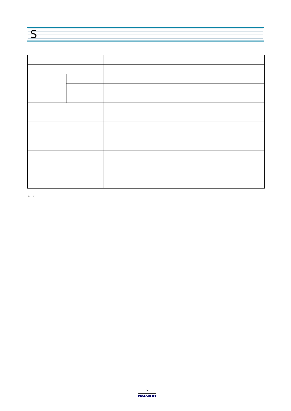
MOD EL KOG -37671S KOG -39671S
POWER SUPPLY 230V~50Hz, SINGLE PHASE WITH EARTHING
POWER
CONSUMPTIO N
MICRO WAVE ENER G Y OU TPUT 850W 950W
MICRO WAVE FREQ UEN CY 2450MHz
OUTSIDE DIMENSIONS (W X H X D)
CAVITY DIMENSIONS (W X H X D)
NET WEIGHT APPROX. 14 Kg (30.9lbs) APPROX. 15.5 Kg (34.2lbs)
TIMER 60 min. DUAL SPEED
FUNCTION SELECTIONS MICROWAVE/GRILL/COMBINATION
POWER SELECTIONS 5 LEVELS
CAVITY VOLU M E 0.7 Cu.F t. 0.9 Cu.F t.
SPECIFICATIONS ARE SUBJECT TO CHANGE WITHOUT NOTIC E.
MICROW AVE 1200W 1350W
GRILL 1050W
COM B INATION 2200W 2350W
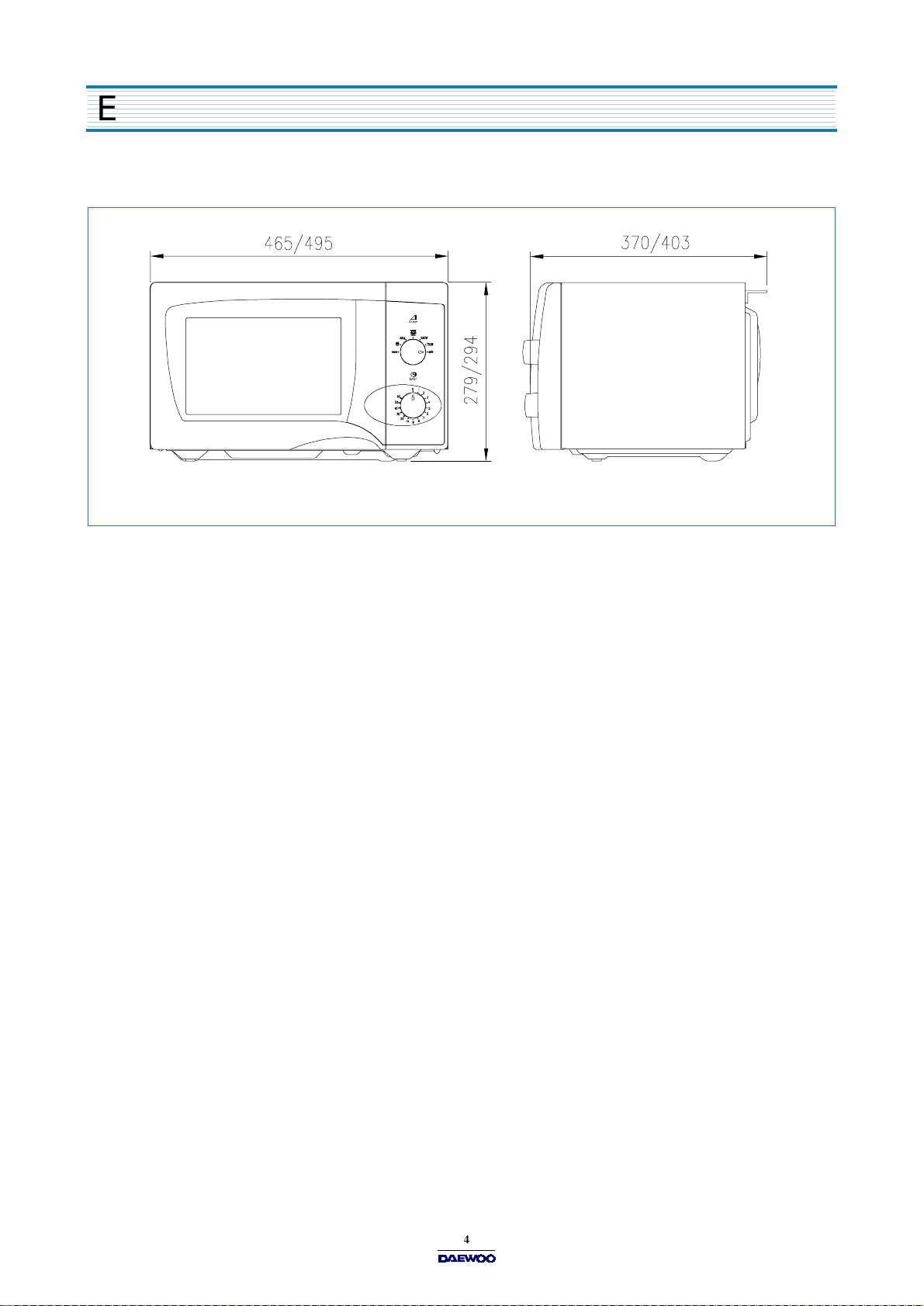
465 X 279 X 370 mm (18.3 X 11.0 X 14.6 in.) 495 X 294 X 403 mm (19.5 X 11.6 X 15.9 in.)
290 X 220 X 306 mm (11.4 X 8.7 X 12.0 in.) 320 X 244 X 338 mm (12.6 X 9.6 X 13.3 in.)
Page 5
EXTERNAL VIEW
1. OUTER D IMENS ION (KO G-376 7/K OG- 396 7)
Fig1. Front view
Fig2. Side view
Page 6
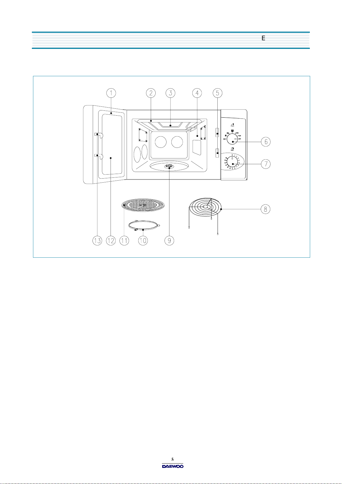
2. FEATURE DIAGRAM
EXTERNAL VIEW
1) Door seal
2) Reflector (Insulator Heater)
3) Heating Element
4) Oven cavity
5) Safety interlock system
6) Knob V.P.C
7) Knob timer
8) Metal Rack
9) Coupler
This is to remain in the oven for all cooking.
10) Roller guide
11) Glass cooking tray
12) Door viewing screen
The screen is designed so that light can pass through, but not the microwave.
13) Door hook
- Door seal maintains the microwave energy within the oven cavity and prevents microwave leakage.
- Used to select a microwave power level.
- Used in setting cooking time for all functions.
- This fits over the shaft in the center of the ovens cavity floor.
- This must always be used for cooking together with the glass cooking tray.
- Made of special heat resistant glass.
Food in a proper receptacle is placed on this tray for cooking.
- Allows viewing of food.
- When the door is closed, it will automatically shut off.
If the door is opened while the oven is operating, the magnetron will immediately stop operating.
Page 7

INSTALLATION
1. Steady, flat location
This microwave oven should be set on a steady, flat surface.
This microwave oven is designed for counter top use only.
2. Leave space behind and side
All air vents should be kept a clearance. If all vents are covered during operation, the oven may overheat and,
eventually, cause failure.
3. Away from radio and TV sets
Poor television reception and radio interference may result if the oven is located close to a TV, radio, antenna or
feeder and so on. Position the oven as far from them as possible.
4. Away from heating appliances and water taps
Keep the oven away from hot air, steam or splash when choosing a place to position it, or the insulation might be
adversely affected and breakdowns occur.
5. Power supply
•
Check your local power source. This microwave oven requires a current of approximately 11amperes, 230 Volts, 50 Hz.
Power supply cord is about 1.2 meters long.
•
The voltage used must be the same as specified on this oven. Using a higher voltage may result in a fire or other
accident causing oven damage. Using low voltage will cause slow cooking. We are not responsible for damage
resulting from use of this oven with a voltage of ampere fuse other than those specified.
•
This appliance is supplied with cable of special type, which, if damaged, must be repaired with cable of same type.
Such a cable can be purchased from DAEWOO and must be installed by a Qualified Person.
6. Examine the oven after unpacking for any damage such as:
A misaligned door, broken door or a dent in cavity.
If any of the above are visible, DO NOT INSTALL, and notify dealer immediately.
7. Do not operate the oven if it is colder than room temperature.
(This may occur during delivery in cold weather.) Allow the oven to become room temperature before operating.
EARTHING INSTRUCTIONS
This appliance must be earthed. In the event of an electrical short circuit, earthing reduces the risk of the electric shock by providing an escape wire for the electric current. This appliance is equipped with a co rd having a earthin g wire with a earthing plug.
The plug must be plugged into an outlet that is properly installed and earthed.
WARNING
Improper use of the earthing plug can result in a risk of electric shock. Consult a qualified electrician or serviceman if
the earthing instructions are not com pletely understood, or if doubt exists as to whether the appliance is properly
earthed, and either:
If it is necessary to use an extension cord, use only a 3-w ire extension cord that has a 3-blade earthing plug, and a
3- s lot re c e ptac le th a t w ill ac c ep t th e p lug on th e appliance. T he m arked rating of the extension cord should be equal
to or greater than the electrical rating of the appliance, or Do not use an extension cord.
Page 8
OPERA T IONS AND F U NCTIONS
1. Connect the main lead to an electrical outlet.
2. After placing the food in a suitable container,
open the oven door and put it on the glass tray.
The glass tray must always be in place during cooking.
3. Close the door securely.
4. Choose cooking power level by setting V.P.C knob to
the desired position.
Refer to cookbook for recommended power levels.
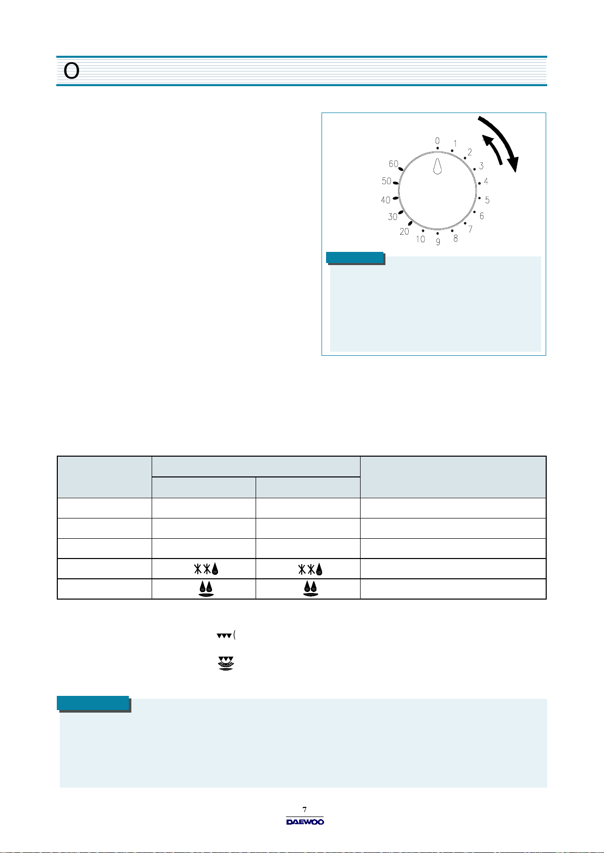
5. Determine cooking time. Consult cookbook for recipe timing.
Oven light turns on and cooling fan starts to operate.
Microwave cooking starts.
6. You may open the door while the oven is operating.
As soon as the door is opened, the safety mechanisms stop the
generation of microwave power and the operation of cooking timer.
If you wish to change the time during cooking,
simply adjust the timer to the desired time.
7. When the timer reaches zero, a bell will ring and the unit will turn off.
Oven light turns off. If additional cooking time is needed and
the door is closed, the oven will automatically start when the timer is reset.
NOTE
1. When setting timer for less than 2 m inutes, turn the
2. Various clicking noises may be heard when turning
tim e r p a s t 2 min u te s an d th e n r e turn to th e c o rre c t
tim e r s e ttin g .
V.P.C knob. This is normal and does not affect the
operation of your m icrowave oven.
•
To set MICROWAVE cooking
Set the variable power selector to the desired power level.
POWER LEVEL
KOG-3767 KOG -3967
HIGH MAX MAX 100 %
MED-HIGH 750W 840W 88 %
MED IUM 620W 690W 73 %
DEFORST 41 %
HEAT 26 %
•
To set GRILL cooking
SYMBOL
APPROXIMATE PERCENTAGE OF POWER
Set the POWER SELECTOR to the (grill) position.
•
To set COMBI cooking
Set the POWER SELECTOR to the (combi) position.
NOTE
W hen using the GRILL or C O M BI mode;
•
Do not open the door so often, the temperature inside the oven decrease and the cooking may not be completed in setting time.
•
Never touch the oven window and metal interior of the oven when taking food in and out, because the temperature inside
the oven and door is very high.
•
When using these modes, be careful as the tray will be hot to touch, use oven gloves or pot holders while handling tray.
Page 9
DISAS SEMBLY AN D ASSEMB LY
Cautions to be observed when trouble shooting.
Unlike many other appliances, the microwave oven is high-voltage, high-current equipment.
It is completely safe during normal operation.
However, carelessness in servicing the oven can result in an electric shock or possible danger from a short circuit.
You are asked to observe the following precautions carefully.
1. Always remove the power plug from the outlet before servicing.
2. Use an insulated screwdriver and wear rubber gloves when servicing the high voltage side.
3. Discharge the high voltage capacitor before touching any oven components or wiring.
(1) Check the earthed.
Do not operate on a two-wire extension cord.
The microwave oven is designed to be used while earthed.
It is imperative, therefore, to makes sure it is earthed properly
before beginning repair work.
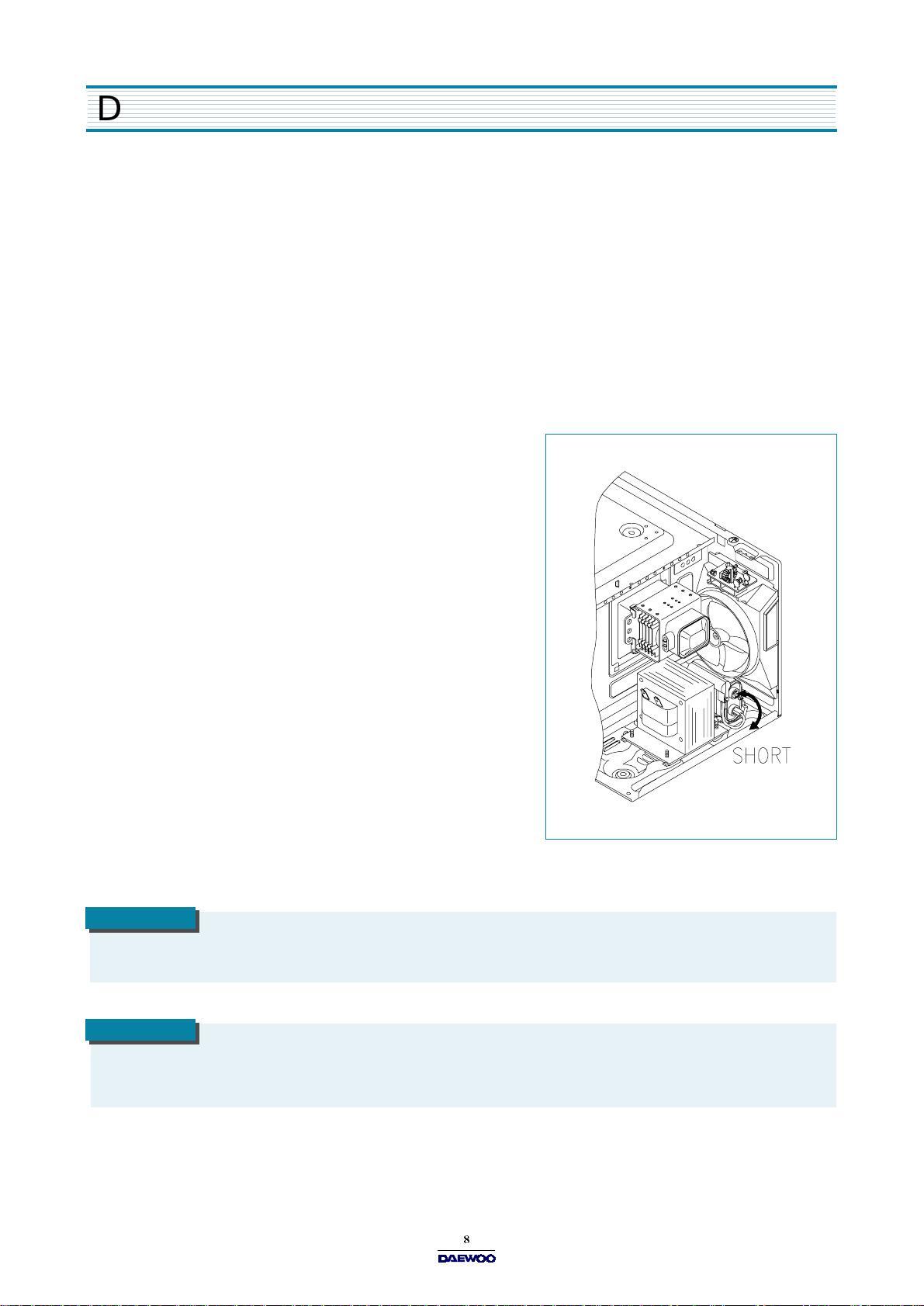
(2) Warning about the electric charge in the high voltage capacitor.
For about 30 seconds after the operation has stopped an electric
charge remains in the high voltage capacitor.
When replacing or checking parts, short between oven chassis and
the negative high terminal of the high voltage capacitor
by using a properly insulated screwdriver to discharge.
4. When the 15A fuse is blown due to the operation of the monitor
switch; replace primary interlock switch, secondary interlock
switch and interlock monitor switch.
5. After repair or replacement of parts, make sure that the screws are
properly tightened, and all electrical connections are tightened.
6. Do not operate without cabinet.
CAUTION
Service personnel should remove their watches whenever working close to or replacing the m agnetron.
WARNIN G
W hen servicing the appliance, take a care when touching or replacing high potential parts because of electrical shock
or exposing microwave. These parts are as follows - HV Transformer, Magnetron, H V C apacitor, H V Diode, HV Fuse.
Page 10
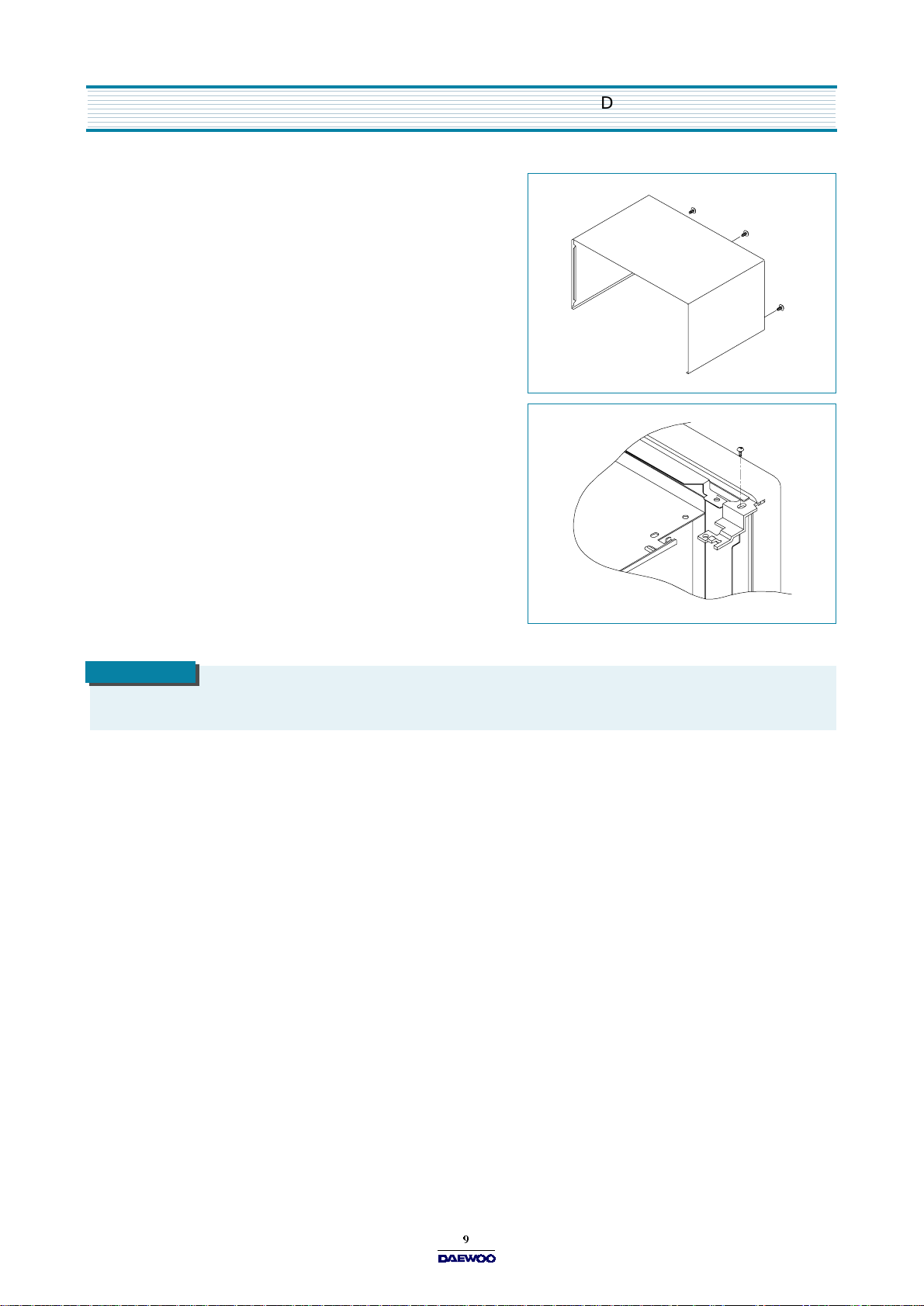
1. To remove cabinet
(1) Remove three screws on cabinet back.
(2) Push the cabinet backward.
2. To remove door assembly
(1) Remove a screw which secure the stopper hinge top.
(2) Remove the door assembly from top plate of cavity.
(3) Reverse the above steps for reassembly.
D ISASSEMBLY AND ASSEMB LY
CAUTION
After replacing the door assembly, perform a check of correct alignment with the hinge and cavity front plate.
Page 11

D ISASSE MBLY AND A SSE M B LY
3. To remove door parts.
1) KOG-37671S
REF.NO PART CODE PART NAME DESCRIPTION QTY REMARK
A01 3512203830 FRAM E D OO R ABS 1
A02 3517005610 BARRIER-SCR EEN *O PMM A 1.5t 1
A03 3515306500 SUPPO TE R BA RR-S*O ABS 1
A04 3511603800 DECO RATOR DO O R ABS 1
A05 3511706100 DOO R PAINTING AS KOR-61150S 1
A06 3517002800 BARRIER-SCR EEN *I KO R-61150S PE 0.1t 1
A07 3515204110 STOPPE R H INGE*T AS KOR-636T1S SCP T2.6 1
A08 3515101310 SPRING H OO K H SW -3 1
A09 3513100730 HOO K KOR-6325 POM 1
A10 7122401211 SCRE W TAPPING T2S TRS 4X12 M FZN 1
A11 3512300200 G AS KET D OO R KOR-61150S PP 1
2) KOG-39671S
REF.NO PART CODE PART N AME DESCRIPTION QTY REMARK
A01 3512204130 FR AM E D OO R ABS 1
A02 3517005710 B AR RIER-SCREEN *O PMMA 1.5t 1
A03 3515306600 S UP POTE R BA RR-S*O AB S 1
A04 3511604000 D EC OR ATOR DOO R ABS 1
A05 3511711800 DOO R PAINTING AS KOR-866T1S 1
A06 3517006000 B AR RIER-SCREEN *I KOR-866T1S PE 0.1t 1
A07 3515204110 S TOPP ER H INGE*T AS KOR-636T1S SCP T2.6 1
A08 3515101310 S PR ING HOO K HSW -3 1
A09 3513100730 H O OK KOR-6325 POM 1
A10 7122401211 S CR EW TAPPING T2S TR S 4X12 M FZN 1
A11 3512302000 GA SKET DO OR KOR-86671S PP 1
Page 12

(1) Remove the gasket door from door plate.
(2) Remove a screw which secure the door plate and door frame.
(3) Remove the door frame from door plate.
(4) Remove the stopper hinge top from door plate.
(5) Remove the spring and the hook.
(6) Remove the supporter barrier screen outer from door frame.
(7) Remove the barrier screen outer from door frame.
(8) Remove the decorator door from door frame.
(9) Reverse the above steps for reassembly.
4. Method to reduce the gap between the door seal and the oven front surface.
(1) To reduce gap located on part A.
Loosen a screw on stopper hinge top, and then push the door to
contact the door seal to oven front surface.
Tighten a screw.
(2) To reduce gap located on part B.
Loosen two screws on stopper hinge under, and then push
the door to contact the door seal to oven front surface.
Tighten two screws.
D ISASSEMBLY AND ASSEMB LY
NOTE
A small gap may be acceptable if the microwave leakage does not exceed 4mW /cm2.
Page 13

D ISASSE MBLY AND A SSE M B LY
5. To remove control panel parts.
REF.NO PART CODE PART NAME DESCRIPTION QTY REMARK
B01
B02
B03 4415A17352 SW MICR O VP-533A-OF 1
B04 4415A66910 SW MICR O VP-531A-OF 1
B05 3513405540 KNOB VP C ABS 1
B06 3515101600 SPRING F LAT SUS 301 T0.5 1
B07 3517400510 COUP LER VP C KN O B POM 1
B08 7122401211 SC REW TAPPING T2S TRS 4X12 M FZN 1
B09 3517400400 COUP LER VP C KN O B POM 1
B10 3513405430 KNOB ABS 1
B11 3518205100 T IMER KN60M KD 12E-P 1
B12 7122401211 SC REW TAPPING T2S TRS 4X12 M FZN 2
3516719030
3516719330 KOG -3967
3511603910
3511604110 KOG -3967
CONTROL-PANEL
DECORATOR C-PANEL ABS 1
ABS 1
KOG -3767
KOG -3767
(1) Remove the screw which secure the control panel, push up two snap fits and draw forward the control panel assembly.
(2) Remove two screws which secure the timer assembly.
(3) Remove the timer assembly.
(4) Pull out the timer knob from the timer.
(5) Pull out the timer coupler from the timer.
(6) Remove the screw which secure the V.P.C coupler.
(7) Pull out the V.P.C coupler, V.P.C knob and flat spring from the control panel.
(8) Remove two switches from the control panel.
(9) Remove thd decorator c-panel from the control panel.
(10) Reverse the above steps for reassembly.
Page 14

6. To remove high voltage capacitor.
(1) Remove a screw which secure the grounding ring terminal
of the H.V.diode and the capacitor holder.
(2) Remove the H.V. diode from the capacitor holder.
(3) Reverse the above steps for reassembly.
High voltage circuit wirng
D ISASSEMBLY AND ASSEMB LY
7. To remove magnetron.
(1) Remove a screw which secure the magnetron.
(2) Remove the magnetron.
(3) Reverse the above steps for reassembly.
CAUTION
Never install the magnetron without the metallic g a s k e t p la t e wh ic h is p a c k ed with e a c h magnetron to prevent microwave leakage. Whenever repair work is carried out on magnetron, check the microwave leakage. It shall not exceed
4mW/cm
2
for a fully assembled oven with door norm ally closed.
Page 15

D ISASSE MBLY AND A SSE M B LY
8. To remove wind guide assembly.
(1) Remove a screw for earthing.
(2) Remove the noise filter from the wind guide.
(3) Remove a screw which secure the wind guide assembly.
(4) Draw forward the wind guide assembly.
(5) Pull the fan from the motor shaft.
(6) Remove two screws which secure the motor shaded pole.
(7) Remove the motor shaded pole.
(8) Reverse the above steps for reassembly.
9. To remove H.V.transformer.
(1) Remove four screws holding the H.V.transformer.
(2) Remove the H.V.transformer.
(3) Reverse the above steps for reassembly.
Page 16

10. To remove tray motor.
(1) Remove the coupler in the cavity.
(2) Turn the set upside down.
(3) Cut the tray motor cover part from the base plate.
(4) Remove the tray motor cover.
(5) Remove a screw which secure the tray motor.
(6) Remove the tray motor.
(7) Reverse the above steps for reassembly except for
securing the tray motor cover with screw.
D ISASSEMBLY AND ASSEMB LY
11. To remove heater assembly.
(1) Remove the three nuts.
(2) Remove the insulator heater assembly.
(3) Reverse the above steps for reassembly.
Page 17

D ISASSE MBLY AND A SSE M B LY
12. To remove heater parts.
INSULATOR HEATER AS: 3513302700
REF.NO PART CODE PART NAME DESCRIPTION QTY REMARK
C01 7392500008 NUT HE X 6N-2-5 SU S 1
C02 3515000600 SPACER INSULATOR *I C3771BD 2
C03 3513301100 INSULATOR HE ATER SPP T0.8 1
C04 3512803400 HEATER 230V 1000W 1R67994001 1
C05 7002500613 SCR EW M AC HINE TRS 5X6 M FCR 1
C06 7002400413 SCR EW M AC HINE TRS 4X4 M FCR 2
Page 18

INTER L OCK MECHANISM AND ADJUSTME NT
The door lock mechanism is a device which has been specially designed to completely eliminate microwave radiation when the
door is opened during operation, and thus to perfectly prevent the danger resulting from the leakage of microwave.
1. Primary interlock switch
When the door is closed, the hook locks
the oven door. If the door is not closed properly,
the oven will not operate. When the door is closed,
the hook pushes the button of the microswitch.
Then the button of the primary interlock switch bring
it under “ON” condition.
2. Secondary interlock switch and interlock
monitor switch.
When the door is closed, the hook pushes the lock
lever downward. The lock lever presses the button of the
interlock monitor switch to bring it under “OFF” condition
and presses the button of the secondary interlock switch
to bring it under “ON” condition.
ADJUSTM ENT
Interlock monitor switch
When the door is closed, the interlock monitor switch should be opened before other switches are closed.
When the door is opened, the interlock monitor switch should be closed after other switches are opened.
3. Adjustment steps
(1) Loosen the one mounting screw.
(2) Adjust interlock switch assembly position.
(3) Make sure that lock lever moves smoothly after adjustment is completed.
(4) Tighten completely one mounting screw.
NOTE
Microwave emission test should be performed after adjusting interlock mechanism.
If the microwave emission exceed 4mW/cm
2
, readjust interlock mechanism.
Page 19

TROUBLE SHOOTING GUIDE
Following the procedures below to check if the oven is defective or not.
1. Check grounding before checking trouble.
2. Be careful of the high voltage circuit.
3. Discharge the high voltage capacitor.
4. When checking the continuity of the switches, fuse or high voltage transformer, disconnect one lead wire from these parts
and then check continuity with the AC plug removed. To do otherwise may result in a false reading or damage to your meter.
(TROUBLE 1)
Door shut, timer set, but no cooking takes place.
Does the fan mo tor work when you
shut the door and turn the timer?
NO
Does the
YES
fu s e blow?
NO
YES (Refer to next page)
Chec k con tinuity of in terlock
monitor switch with door shut.
NO Continuity
Replace fuse and check
continuity of both interlock
sw itch's contact and mo nitor
sw itch's contact with door
partially open until monitor
sw itch contact.
Both continuity
Continuity
NO
Replace primary, secondary
interlock switch and inte rlock
monitor switch.
Replace primary, secondary
interlock switch and inte rlock
monitor switch.
Disconnect one side of the
lead wire connected from
transforme r to the high vo ltage
capacitor, and o perate ove n.
If outlet has proper voltage,
check continuity of pow er.
Fuse again
NO Continuity
Normal
Replace high
voltage
capacitor.
Replace high
voltage transformer
Replace power
supp ly cord.
Page 20

Does the fan motor work when you shut
read ing s h ould
Check continuity filamen t
tap (3.3V) of high voltage.
continuity in the reverse and
Replace
ma gnetron.
Meter with 6 V or highe r
voltage batteries should
Good
NO Good
Poor continuity
the door and turn the timer?
YES
TROUBLE SHOOTING GUIDE
Does the oven lam p light?
D oe s the turn tab le turn ?
YES
If microwave do not oscillate,
check continuity of filament
of magnetron .
NO
NO
Continuity
Normal
be approx. 0
Ω
Continuity
Check the diode for
normal dire ction s.
Continuity
NO C ontinuity
Continuity in
the reve rse
directio n.
Replace or repair oven lam p,
turntable motor.
Replace hig h
voltage
transformer.
Replace hig h
voltage diode.
Replace
ma gnetron.
Check the isolation of
filament winding of high
voltage transforme r.
be used to check the normal
directio n resistan ce of
the diode.
Replace hig h
voltage
transformer.
Page 21

ME ASUREMENT AND TE ST
1. MEASUREMENT OF THE MICROWAVE POWER OUTPUT
Microwave output power can be checked by indirectly measuring the temperature rise of a certain amount of water exposed to
the microwave as directed below.
PROCEDURE
1. Microwave power output measurement is made with the microwave oven supplied at rated voltage and operated at its
maximum microwave power setting with a load of 1000 ± 5cc of potable water.
2. The water is contained in a cylindrical borosilicate glass vessel having a maximum material thickness of 3 mm and an ou tside
diameter of approximately 190 mm.
3. The oven and the empty vessel are at ambient temperature prior to the start of the test. The initial temperature of the wate r is
10 ± 2 °C (50 ± 3.6 °F). It is measured immediately before the water is added to the vessel. After addition of the water to the
vessel, the load is immediately placed on the center of the shelf, which is in the lowest normal position.
4. Microwave power is switched on.
5. Heating time should be exactly A seconds.
(Refer to table as following).
Heating time is measured while the microwave generator is
operating at full power. The filament heat-up time for
magnetron is not included.
6. The initial and final temperature of water is selected
so that the maximum difference between the ambient and
final water temperature is 5K.
7. The microwave power output P in watts is calculated
from the following formula:
P = 4187
•
T is difference between initial and ending temperature.
•
t is the heating time.
The power measured should be B (Refer to 2. SPECIFICATIONS) W ± 10.0 %.
T/t
caution
1. Water load should be measured exactly to 1 liter.
2. Input power voltage should be exactly specified voltage (Refer to SPECIFICATIONS).
3. Ambient temperature should be 20
268
3.6
NOTE
Microwave emission test should be performed after adjusting interlock mechanism. If the m icrowave emission
exceed 4mW /cm
Heating time for power output
A (second)
B (W)
2
, readjust interlock m echanism.
70 64 60 56 52 49 47 44 42 40 38
600 650 700 750 800 850 900 950 1000 1050 1100
Page 22

MEASUR E MENT AND TEST
2. MICROWAVE RADIATION TEST
WARNING
Make sure to check the microwave leakage before and after repair of adjustment.
Always start measuring of an unknow n field to assure safety for operating personnel from microw ave energy.
Do not place your hands into any suspected m icrowave radiation field unless the safe density level is known.
Care should be taken not to place the eyes in direct line with the source of microwave energy.
Slowly approach the unit under test until the radiom eter reads an appreciable microw ave leakage from the unit under the test.
PROCEDURE
1. Prepare Microwave Energy Survey Meter, 600cc glass beaker,
and glass thermometer 100°C (212°F ).
2. Pour 275cc ±15cc of tap water initially at 20 ± 5 °C (68 ± 9°F) in
the 600 cc glass beaker with an inside
diameter of approx. 95 mm(3.5 in.).
3. Place it at the center of the tray and set it in a cavity.
4. Close the door and operate the oven.
5. Measure the leakage by using Microwave Energy Survey
Meter with dual ranges, set to 2450MHz.
(1) Measured radiation leakage must not exceed the value
prescribed below. Leakage for a fully assembled oven with
2
door normally closed must be less than 4mW/cm
(2) When measuring the leakage, always use the 5 cm (2 in.)
space cone with probe. Hold the probe perpendicular to the
cabinet and door.
Place the space cone of the probe on the door, cabinet,
door seem, door viewing screen,
the exhaust air vents and the suction air vents.
(3) Measuring should be in a counter-clockwise direction at a rate of 1 in./sec.
If the leakage of the cabinet door seem is unknown, move the probe more slowly.
(4) When measuring near a corner of the door, keep the probe perpendicular to the areas making sure the probe end at
the base of the cone does not get closer than 2 in. from any metal. If it does not, erroneous reading may result.
.
Page 23

MEASUR E MENT AND TEST
3. COMPONENT TEST PROCEDURE
High voltage is present at the high voltage terminal of the high voltage transformer during any cooking cycle.
It is neither necessary nor advisable to attempt measurement of the high voltage.
Before touching any oven components or wiring, always unplug the oven from its power source and discharge the capacitor.
1. High voltage transfo rmer
(1) Remove connections from the transformer terminals and check continuity.
(2) Normal readings should be as follows :
Secondary winding ... Approx. 110± 10%
Filament winding .......Approx. 0
Primary winding ....... Approx. 0
2. High voltage capacitor
(1) Check continuity of capacitor with meter on the highest OHM scale.
(2) A normal capacitor will show continuity for a short time, and then indicate 10M
(3) A shorted capacitor will show continuous continuity.
(4) An open capacitor will show constant 10M.
(5) Resistance between each terminal and chassis should be infinite.
once the capacitor charged.
3. High voltage diode
(1) Isolate the diode from the circuit by disconnecting the leads.
(2) With the ohmmeter set on the highest resistance scale measure the resistance across the diode terminals. Reverse the
meter leads and again observe the resistance reading. Meter with 6v, 9v or higher voltage batteries should be used to
check the front-back resistance of the diode, otherwise an infinite resistance may be read in both directions. A normal
diode's resistance will be infinite in one direction and several hundred k
4. Magnetron
in the other direction.
For complete magnetron diagnosis, refer to “Measurement of the Microwave Output Power."
Continuity checks can only indicate and open filament or a shorted magnetron.
To diagnose for an open filament or a shorted magnetron,
(1) Isolate magnetron from the circuit by disconnecting the leads.
(2) The continuity check across magnetron filament terminals should indicate 0.1
or less.
(3) The continuity check between each filament terminal and magnetron case should read open.
5. Fuse
If the fuse in the primary and monitor switch circuit is blown when the door is opened, check the primary and monitor switch
before replacing the blown fuse. In case the fuse is blown by an improper switch operation, replace the defective
switch and fuse at the same time. Replace just the fuse if the switches operate normally.
Page 24

WIRING DIAG RAM
1. KOG-376 71S
Page 25

W IRING D IAGR AM
2. KOG-396 71S
Page 26

EXPLODED VIEW AND PARTS LIST
1. DOOR ASSEMBLY
Refer to 6.Disassembly and assembly.
2. CONTROL PANEL ASSEMBLY
Refer to 6.Disassembly and assembly.
3. TOTAL ASSEMBLY
(1) KOG-37671S
Page 27

EXPLODED VIEW AND PARTS LIST
- R : PART RECOMMENDED FOR STOCK
NO. R PART CODE PART NAME DESCRIPTION SUPPLY REM ARK
A00 3511710350 DOOR AS KOR-63671S O Refer to Page 10
B00 3516720340 CONTROL-PANEL AS KOG-37671S O Refer to Page 12
C00 3513302700 INSULATOR HEAT ER AS KOG-3715 0S O Refer to Page 16
F01 3510801310 CABINET PCM T0.6 GE O
F02 7S312X40A1 SCREW SPECIAL T1 TRS 4X10 SE MFZN O
F03 3516109010 CAVITY WELD AS KOG-37150S
3516109610 CAVITY JOINT AS KOG-37150S
F04 7S627W50X1 NUT HEX NUT FLA NGE M5X0. 8P MFZN O
F05 7122401211 SCREW TAPPING T2S TRS 4X12 MFZN O
F06 3518904500 THERMOSTAT OFF:100 ON:90 HN #187 O
F07 7121300611 SCREW TAPPING T2S PAN 3X6 MFZN O
F08 7122401211 SCREW TAPPING T2S TRS 4X12 MFZN O
F09 7112401011 SCREW TAPPING T1 TRS 4X10 MFZN O
F10 35113A5QJ5 CORD POWER AS 3X1.5 80X80 120-RTML O
F11 4413A 90012 CLAMP POWER CORD NYLON66 O
F12 7S312X40A1 SCREW SPECIAL T1 TRS 4X10 SE MFZN O
F13 7122401211 SCREW TAPPING T2S TRS 4X12 MFZN O
F14 7S627W50X1 NUT HEX NUT FL M5X0. 8P MFZN O
F15 4414A25110
4414A25100 250V 15A MDA15
F16 3518606100 NOISE-FILTER DWLF-M13 O
F17 7121403011 SCREW TAPPING T2S PAN 4X30 MFZN O
F18 3512517000 GUIDE WIND PP O
F19 3963513100 MOTOR SHADED POLE 230V 17W OEM-10DWC2- A07 O
F20 3511800300 FAN PP+30%GLASS O
F21 R 3518002200 MAGNETRON 2M218H(MF) I O
F22 3516004000 SPECIAL SCREW T2 BOLT FL 5X12 DACRO O
F23 7S 422X408 1 SPECIAL SCRE W TT2 TRS 4X8 SE MFZN O
F24 3513003200 HOLDER HV CAPACITOR SECC T0.6 O
F25 R 3518302200 CAPACITOR HV
F26 R 3518400400 DIODE HV HVR-1X-3AB 12KV #187 O
F27 R 3518701100 FUSE HV 5KV 0.55A HV-41A55-02 #187 O
F28 R 3518115300 TRA NS HV DW-N85S0-63T O
F29 3516003700 SPECIAL SCREW TT3 HEX 4X8 FLG MFZN O
F30 3510311700 BASE SBHG T0.8 O
F31 7112401011 SCREW TAPPING T1 TRS 4X10 MFZN O
F32 3512100900 FOOT PP DASF-130 O
F33 7S 422X408 1 SCRE W SPECIAL TT2 TRS 4X8 SE MFZN O
F34 3515201101 STOPPER HINGE*U SCP-1 T2.5 O
FUSE
250V 15A 65TS
2100VAC 0.98µ
F #187 O
O
O
Page 28

EXPLODED VIEW AND PARTS LIST
NO. R PART CODE PART NAME DESCRIPTION SUPPLY REMARK
F35 7122401211 SCREW TAPPING T2S TRS 4X12 MFZN O
F36 R 3518570400 SWITCH S/A RELAY DWSR-1 O
F37 R 4415A17352 SW MICRO VP-533A-OF SPNO #187 200G O PRIMARY
F38 R 4415A66910 SW MICRO VP-531A-OF/SZM-V16-FA-61 O MONITOR
F39 R 4415A17352 SW MICRO VP-533A-OF SPNO #187 200G O SECONDARY
F40 3513702600 LEVER LOCK POM O
F41 3513811710 LOCK POM O
F42 3513601600 LAMP BL 240V 25W T25 C7A H187 O
F43 7121400611 SCREW TAPPING T2S PAN 4X6 MFZN O
F44 R 3966310100 MOTOR SYNCRO 220V 2.5W GM-16-24FD12 O
F45 3518905300 THERMOSTAT OFF:75 ON:65 H #187 NB O
F46 3513003400 HOLDER THERMOSTAT PBT O
F47 3516003700 SCREW SPECIAL TT3 HEX 4X8 FLG MFZN O
F48 4078502031 BUTTON LOCKING PP HONAM A353 O
F49 3511405100 COVER WAVE GUIDE MICA T0.35 O
F50 3517400620 COUPLER XAREC O
F51 3514700710 ROLLER TEFLON X
F52 3512517300 GUIDE ROLLER PP 5113MF6 A353B X
3512517500 GUIDE ROLLER AS KOR-63150S O
F53 3517203600 TRAY GLASS O
F54 3517206900 TRAY RACK AS KOG-37150S 110MM O
Page 29

EXPLODED VIEW AND PARTS LIST
(2) KOG-39671S
Page 30

EXPLODED VIEW AND PARTS LIST
- R : PART RECOMMENDED FOR STOCK
NO. R PART CODE PART NAME DESCRIPTION SUPPLY REMARK
A00 3511710770 DOOR AS KOR-86671S O Refer to Page 10
B00 3516720830 CONTROL-PANEL AS KOG-39671S O Refer to Page 12
C00 3513302700 INSULATOR HEATER AS KOG-37150S O Refer to Page 16
F01 3510801400 CABINET PCM T0.6 GE O
F02 7S312X40A1 SCREW SPECIAL T1 TRS 4X10 SE MFZN O
F03 3516109210 CAVITY WELD AS KOG-39150S
3516109710 CAVITY JOINT AS KOG-39150S
F04 7S627W50X1 NUT HEX NUT FLANG E M5X0.8P MFZN O
F05 7122401211 SCREW TAPPING T2S TRS 4X12 MFZN O
F06 3518904500 THERMOSTAT OFF:100 ON:90 HN #187 O
F07 7121300611 SCREW TAPPING T2S PAN 3X6 MFZN O
F08 7122401211 SCREW TAPPING T2S TRS 4X12 MFZN O
F09 7112401011 SCREW TAPPING T1 TRS 4X10 MFZN O
F10 35113A5QJ5 CORD POWER AS 3X1.5 80X80 120-RTML O
F11 4413A90012 CLAMP POWER CORD NYLON66 O
F12 7S312X40A1 SCREW SPECIAL T1 TRS 4X10 SE MFZN O
F13 7122401211 SCREW TAPPING T2S TRS 4X12 MFZN O
F14 7S627W50X1 NUT HEX NUT FL M5X0.8P MFZN O
F15 4414A25 110
4414A25100 250V 15A MDA15
F16 3518606100 NOISE-FILTER DWLF-M13 O
F17 7121403011 SCREW TAPPING T2S PAN 4X30 MFZN O
F18 3512517000 GUIDE WIND PP O
F19 3963513100 MOTOR SHADED POLE 230V 17W OEM-10DWC2-A07 O
F20 3511800300 FAN PP+30%GLASS O
F21 7121300611 SCREW TAPPING T2S PAN 3X6 MFZN O
F22 3518903400 THERMOSTAT OFF : 150 ON : 60 V #187 O
F23 R 3518002200 MAGNETRON 2M218H(MF) I O
F24 3516004000 SPECIAL SCREW T2 BOLT FL 5X12 DACRO O
F25 7S422X4081 SPECIAL SCREW TT2 TRS 4X8 SE MFZN O
F26 3513003200 HOLDER HV CAPACITOR SECC T0.6 O
F27 R 3518302200 CAPACITOR HV 2100VAC 0.98mF #187 O
F28 R 3518400400 DI O DE HV HVR-1X-3AB 12KV #187 O
F29 R 3518701100 FUSE HV 5KV 0.55A HV-41A55-02 #187 O
F30 R 3518116000 T RAN S HV JY -N95S 0-86TB O
F31 3516003700 SPECIAL SCREW TT3 HEX 4X8 FLG MFZN O
F32 3510311900 BASE SBHG T0.8 O
F33 7112401011 SCREW TAPPING T1 TRS 4X10 MFZN O
FUSE
250V 15A 65TS
O
O
Page 31

EXPLODED VIEW AND PARTS LIST
NO. R PART CODE PART NAME DESCRIPTION SUPPLY REMARK
F34 3512100900 FOOT PP DASF-130 O
F35 7S422X4081 SCREW SPECIAL TT2 TRS 4X8 SE MFZN O
F36 3515201101 STOPPER HINGE*U SCP-1 T2.5 O
F37 7122401211 SCREW TAPPING T2S TRS 4X12 MFZN O
F38 R 3518570400 SWI T CH S/A RELAY DWSR-1 O
F39 R 4415A173 52 SW MICRO VP-533A-OF SPNO #187 200G O PRIMARY
F40 R 4415A669 10 SW MICRO VP-531A-OF/SZM-V16-FA-61 O MO NITOR
F41 R 4415A173 52 SW MICRO VP-533A-OF SPNO #187 200G O SE CONDA RY
F42 3513702600 LEVER LOCK POM O
F43 3513811710 LOCK POM O
F44 3513601600 LAMP BL 240V 25W T25 C7A H187 O
F45 7121400611 SCREW TAPPING T2S PAN 4X6 MFZN O
F46 R 3966310100 MOTOR SYNCRO 220V 2.5W GM-16-24FD12 O
F47 3518905600 THERMOSTAT OFF : 80 ON : 50 H #187 NB O
F48 3513003400 HOLDER THERMOSTAT PBT O
F49 3516003700 SCREW SPECIAL TT3 HEX 4X8 FLG MFZN O
F50 4078502031 BUTTON LOCKING PP HONAM A353 O
F51 3511405100 COVER WAVE GUIDE MICA T0.35 O
F52 3517400620 COUPLER XAREC O
F53 3514700710 ROLLER TEFLON X
F54 3512509200 GUIDE ROLLER PP 5113MF6 A353B X
3512510600 GUI DE ROLLER AS KOR-63150S O
F55 3517203500 TRAY GLASS O
F56 3517206900 TRAY RACK AS KOG-37150S 110MM O
Page 32

DAEWOO ELECTRONICS CO., LTD
686, AHYEON-DONG MAPO-GU
SEOUL, KOREA
C.P.O. BOX 8003 SEOUL, KOREA
TELEX : DWELEC K28177-8
CABLE : “DAEW OOELEC”
E-mail : G7F00E@web.dwe.co.kr
FAX : 032) 510-7630
TEL : 032) 510-7618
PRINTED DATE : SEP. 1999
 Loading...