

Page 1

S/M No. : G372G0S001
Service Manual
Microwave Oven
Model: KOG-372G0S
KOG-372H0S
KOG-392G0S
KOG-392H0S
DAEWOO ELECTRONICS CO., LTD.
Page 2
PRECAUTIONS TO BE OBSERVED BEFORE AND
DURING SERVICING TO AVOID POSSIBLE
EXPOSURE TO EXCESSI VE MICR OWAV E ENERGY
(a) Do not operate or allow the oven to be operated with the door open.
(b) Make the following safety checks on all ovens to be serviced before activating the magnetron or other microwave
source, and make repairs as necessary: (1) Interlock operation, (2) Proper door closing, (3) Seal and sealing
surfaces (arcing, wear, and other damage), (4) Damage to or loosening of hinges and latches, (5) Evidence of
dropping or abuse.
(c) Before turning on power to the microwave oven for any service test or inspection within the microwave
generating compartments, check the magnetron, wave guide or transmission line, and cavity for proper
alignment, integrity, and connections.
(d) Any defective or misadjusted components in the interlock, monitor, door seal, and microwave generation and
transmission systems shall be repaired, replaced, or adjusted by procedures described in this manual before the
oven is released to the owner.
(e) A microwave leakage check to verify compliance with the Federal performance standard should be performed on
each oven prior to release to the owner.
SAFETY AND PRECAUTIONS........................................................................................................... 2
1. FOR SAFE OPERATION .............................................................................................................. 2
2. FOR SAFE SERVICE PROCEDURES ......................................................................................... 2
SPECIFICATIONS............................................................................................................................... 3
EXTERNAL VIEW................................................................................................................................ 4
1. OUTER DIMENSION..................................................................................................................... 4
2. FEATURE DIAGRAM.................................................................................................................... 5
3. CONTROL PANEL........................................................................................................................ 6
INSTALLATI ON ............... .................. ............... .................. ............... ................. ............... ................. 8
OPERATIONS AND FUNCTIONS....................................................................................................... 9
DISASSEMBLY AND ASSEMBLY...................................................................................................... 10
INTERLOCK MECHANISM AND ADJUSTMENT............................................................................... 19
TROUBLE SHOOTING GUIDE .......... ... ......... ... .................. ... ......... ... ........ ... ... ......... ... ......... ... ........... 20
MEASUREMENT AND TEST...................................................... ......... ................. ......... ......... ........... . 24
1. MEASUREMENT OF THE MICROWAVE POWER OUTPUT ...................................................... 24
2. MICROWAVE RADIATION TEST................................................................................................. 25
3. COMPONENT TEST PROCEDURE............................................................................................. 26
WIRING DIAGRAM.............................................................................................................................. 27
PRINTED CIRCUIT BOARD................................................................................................................ 28
1. CIRCUIT CHECK PROCEDURE .................................................................................................. 28
2. PCB CIRCUIT DIAGRAM.............................................................................................................. 31
3. P.C.B. LOCATION NO. ................................................................................................................. 32
EXPLODED VIEW AND PARTS LIST................................................................................................. 34
1. DOOR ASSEMBLY....................................................................................................................... 34
2. CONTROL PANEL ASSEMBLY.................................................................................................... 34
3. TOTAL ASSEMBLY....................................................................................................................... 34
Page 3

SAFETY AND PRE CAUTIONS
1. FOR SAFE OPERATION
Dam age that allows the microwave energy (that cooks or heats the food) to escape will res u lt in poor cooking and m ay cause
serious bodily injury to the operator.
IF ANY OF THE FOLLOWING CONDITION S EXIST, OPERATOR MUST NOT USE THE APPLIAN CE.
(Only a trained service personnel should make repairs.)
1) A broken door hinge.
2) A broken door viewing screen.
3) A broken front panel, oven cavity.
4) A loosened door lock.
5) A broken door lock.
The door gasket plate and oven cavity surface should be kept clean.
No grease, soil or spatter should be allowed to build up on these surfaces or inside the oven.
DO NOT ATTEMPT TO OPERATE THIS APPLIANCE WITH THE DOOR OPEN. The microwave oven has concealed switches
to make sure the power is turned off w hen the door is opened. D o not attempt to defeat them.
DO NOT ATTEMPT TO SERVICE THIS APPLIANCE UNTIL YOU HAVE READ THIS SERVICE MANUAL.
2. FOR SAFE SERVICE PROCEDURES
1) If the oven is operative prior to servicing, a microwave emission check should be perform ed prior to servicing the oven.
2) If any certified oven unit is found to servicing, a microwave em ission check should be performed prior to servicing the oven.
(a) inform the manufacturer, importer or assembler,
(b) repair the unit at no cost to the ow ner,
(c) attempt to ascertain the cause of the excessive leakage,
(d) tell the owner of the unit not to use the unit until the oven has been brought into compliance.
3) If the oven operates with the door open, the service person should tell the user not to operate the oven and contact the
manufacturer im m ediately.
IMPORTA NT
The wire in this m ains lead coloured in accordance w ith the following code.
Green-and-yellow : Earth
Blue : Neutral
Brown : Live
As the colours of the wires in the manins lead of this appliance may not correspond w ith the coloured m arkings
identifying the terminals in your plug, proceed as follows.
The wire which is coloured green-and-yellow m ust be connected to the termianl in the plug w hich is marked with the
letter ‘E’, earth symbol or coloured green-and-yellow.
The wire which is coloured blue m ust be connected to the terminal which is m arked with the letter ‘N’ or
coloured black.
The wire which is coloured brown m ust be connected to the terminal which is marked with the letter ‘L’ or
coloured red.
NOTE
This oven is designed for counter-top use only.
Page 4
SPECIFICATIONS
MOD EL KOG -372G/H KO G-392G/H
POW ER SU PPLY 230V-50Hz, SINGLE PH ASE W ITH EARTHING
MICROW AVE 1200W 1350W
POW ER
CONSUMPTION
MICROWAVE ENERGY OUTPUT 800W 900W
MICROWAVE FREQUENCY 2450MHz
OUTSIDE DIMENSIONS (W X H X D) 465 x 279 x 360mm (18.3 x 11.0 x 14.2 in.) 495 x 294 x 388mm (19.5 x 11.6 x 15.3 in.)
CAVIT Y DIMENS IONS (W X H X D ) 290 x 220 x 306 mm (11.4 x 8.7 x 12.0 in.) 320 x 244 x 338mm (12.6 x 9.6 x 13.3 in.)
NET W E IGHT APPRO X . 13.7Kg (30.2lbs.) APPRO X. 15.8Kg (34.9lbs.)
TIMER 59 min. 90 sec.
FUNCTION SELECTIONS MICROWAVE
POW ER SE LECTIONS 10 LEVELS
GRILL 1050W 1050W
COM BINATIO N 2200W 2350W
CAVIT Y VOLUM E 0.7 C u.Ft. 0.9 C u.Ft.
SPECIFICATIONS ARE SUBJECT TO CHANGE WITHOUT NOTICE.
Page 5
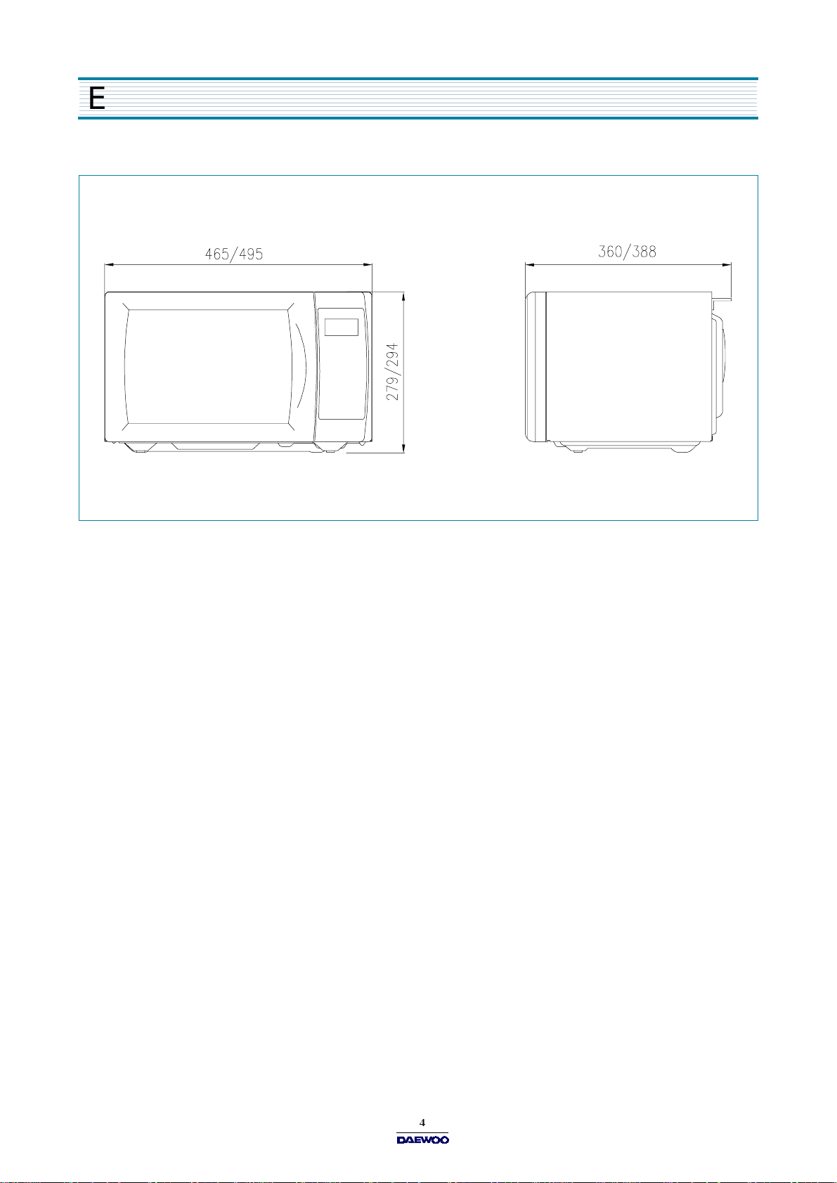
EXTERNAL VIEW
1. OUTER DIMENSION
Page 6
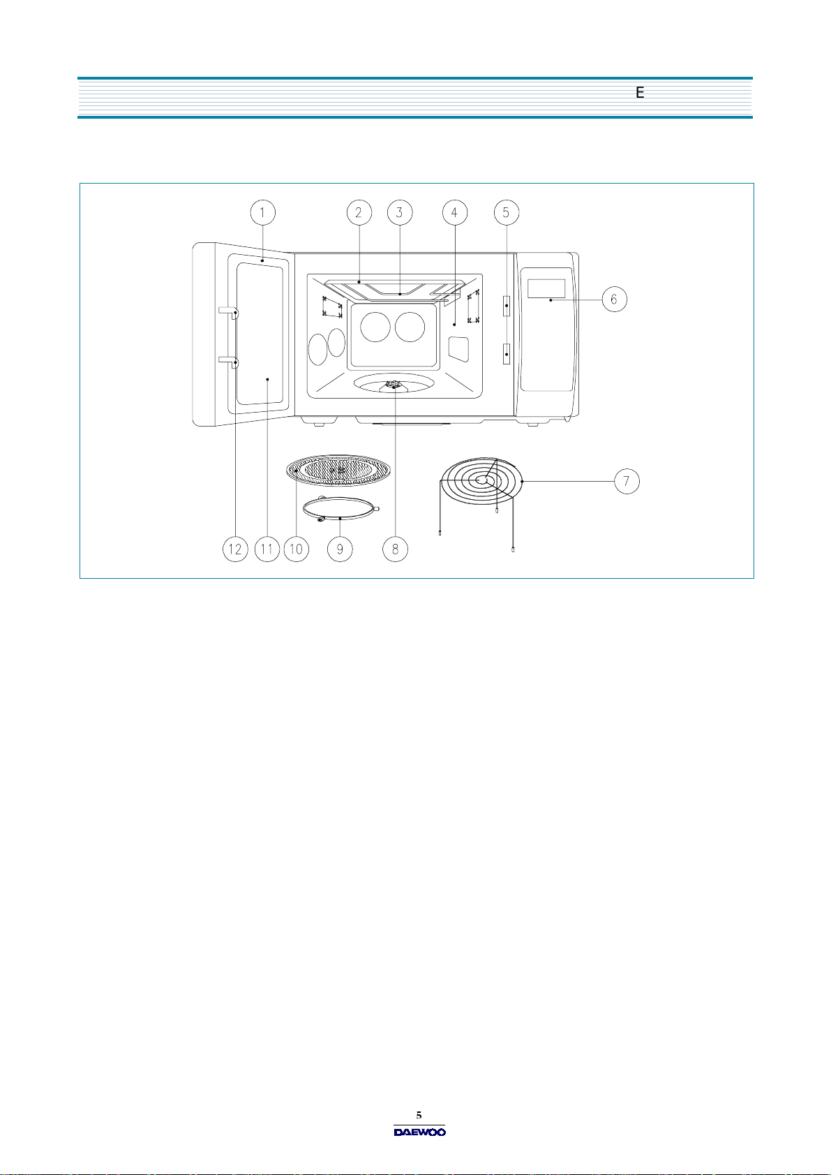
2. FEATURE DIAGRAM
EXTERNAL VIEW
1. DOOR SEAL -
2. REFLECTOR (Insulator Heater)
3. HEATING ELEMENT
4. OVEN CAVITY
5. SEFETY INTERLOCK SYSTEM
6. CONTROL PANEL
7. METAL RACK
8. COUPLER -
9. ROLLER GUIDE -
10. GLASS COOKING TRAY -
cooking.
11. DO OR VIEWING SCREEN -
microwave.
Door seal m aintains the microw ave energy within the oven cavity and prevents m icrowave leakage.
This fits over the shaft in the center of the ovens cavity floor. This is to rem ain in the oven for all cooking.
This must always be used for cooking together with the glass cooking tray.
Made of special heat resistant glass. Food in a proper receptacle is placed on this tray for
Allows viewing of food. The screen is designed so that light can pass through, but not the
12. DOOR HOOK -
the magne tron will imm ediately stop operating.
W he n th e do o r is clos ed , it will a uto matic a l ly s hut off. If the d oo r i s o pe n ed w hile t h e ov e n is operating,
Page 7
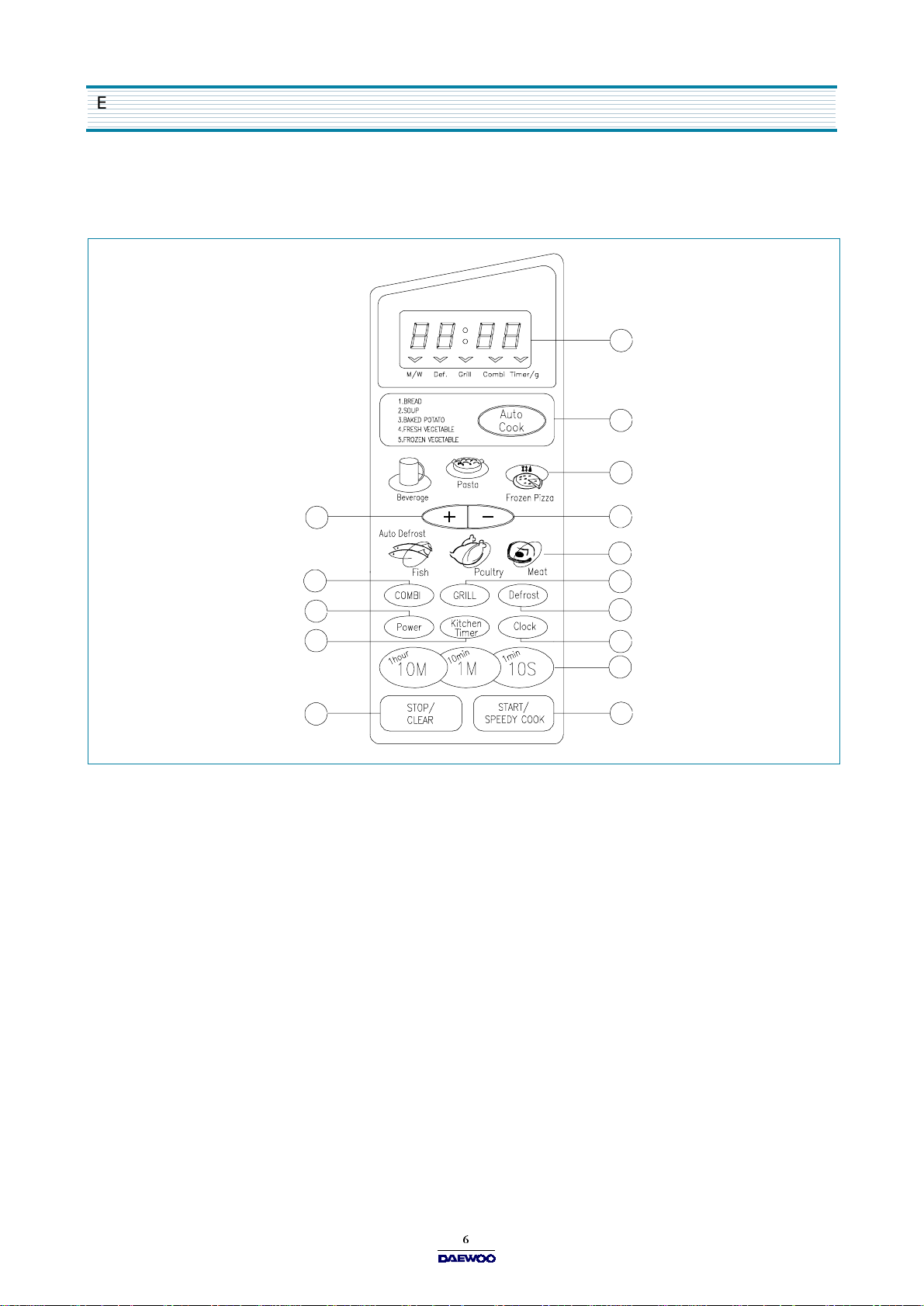
EXTERNAL VIEW
3. CONTROL PANEL
(1) KOG-372G0S/392G0S
2
4
3
1. TIME SET PAD -
2. DISPLAY -
3. ONE TOUCH -
4. AUTO COOK -
5. MORE -
6. LESS -
7. AUTO DEFROST -
Used to add time to cooking.
Us ed to re move tim e from c o ok ing.
Used to set the cooking time and the present tim e.
Cooking tim e, power level, indicators and present time are displayed.
Used to cook or reheat specific quantities of food.
Used to cook or reheat.
5
8
10
12
14
Used to defrost foods.(for weight)
6
7
9
11
13
1
15
8. COMBI -
9. GRILL -
10. POWER -
11. D EFROS T -
12. KITCHEN TIMER -
13. CLOCK -
14. STO P /CL EA R -
15. START/SPEEDY CO OK -
Used to cook C OM BI.
U se d to c oo k GRI L L
Used to set power level.
U se d to de fr os t foo ds . ( for time)
Used as a minute timer, to delay the start of cooking, or to set a holding time after cooking.
Use d to set clock .
Used to stop the oven operation or to delete the cooking data.
Used to start the oven and also used to set a reheat time.
Page 8
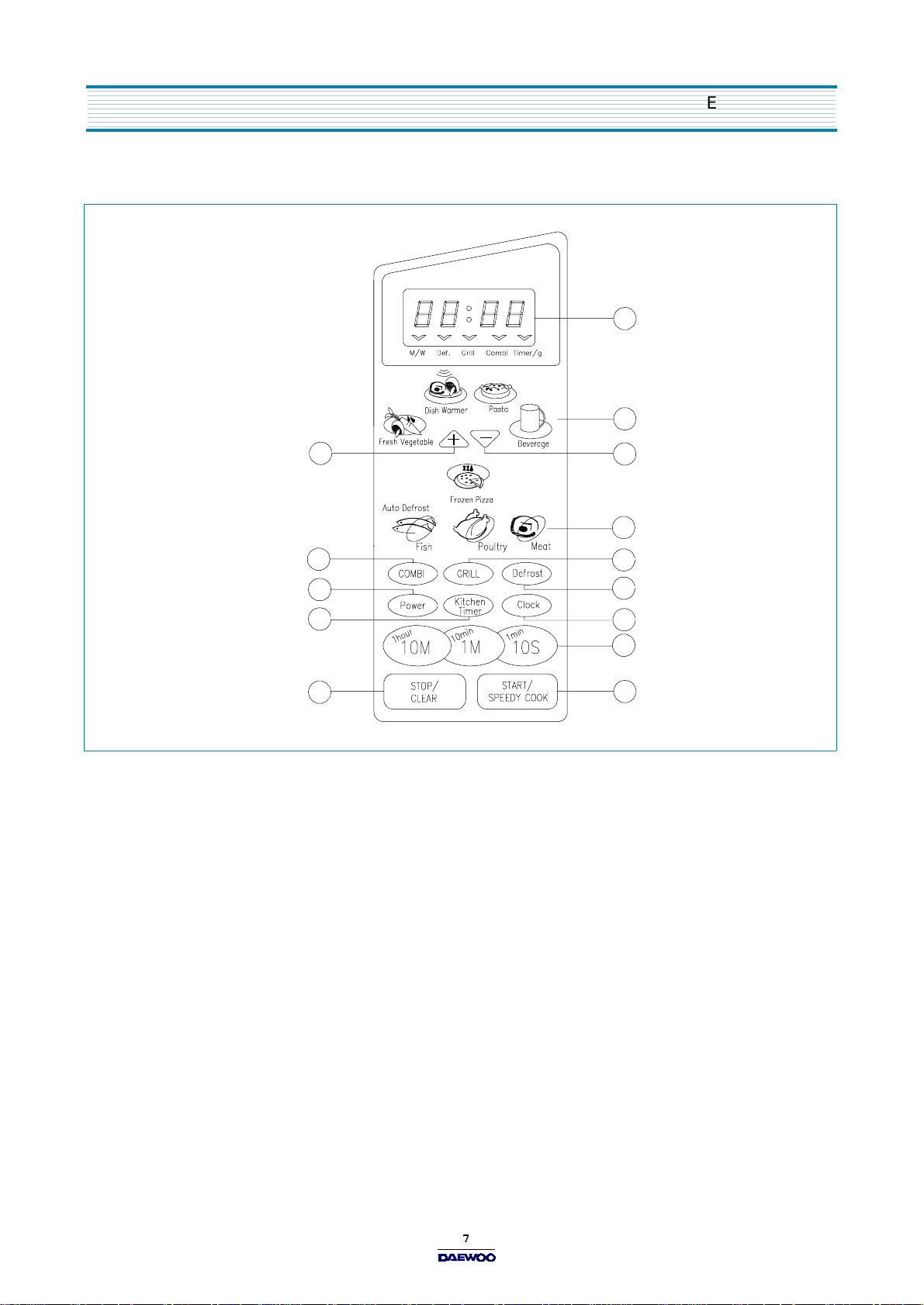
(2) KOG-372H0S/392H0S
EXTERNAL VIEW
2
3
45
4
6
1. TIME SET PAD -
2. DISPLAY -
3. ONE TOUCH-
4. MORE -
5. LESS -
Used to add time to cooking.
Us ed to re move tim e form c o ok ing.
Used to set the cooking time and the present tim e.
Cooking tim e, power level, indicators and present time are displayed.
Used to cook or reheat specific quantities of food.
6. AUTO DEFROST -
7. COMBI -
8. GRILL -
Used to cook C OM BI.
U se d to c oo k GRI L L.
7
9
11
13
Used to defrost foods, (for weight)
8
10
12
1
14
9. POWER -
10. D EFROS T -
11. KITCHEN TIMER -
12. CLOCK -
13. STO P /CL EA R -
U se d to se t powe r l e ve l.
U se d to de fr os t foo ds . ( for time)
Used as a minute timer, to delay the start of cooking, or to set a holding time after cooking.
Use d to set clock .
Used to stop the oven operation or to delete the cooking data.
14. START/SPEEDY CO OK -
Used to start the oven and also used to set a reheat time.
Page 9

INSTALLATION
1. Stead y, flat location
This microwave oven should be set on a steady, flat surface.
This microwave oven is designed for counter top use only.
2. Leave space behind an d side
All air vents should be kept a clearance. If all vents are covered during operation, the oven m ay overheat and, eventually,
cause failure.
3. Away from radio and TV sets
Poor television reception an d radio interference may result if the o ven is located close to a TV, radio, antenna or feeder and so on.
Positio n the oven as far from them as possible.
4. Away from heating appliances and water taps
Keep the oven away from hot air, steam or splash w hen choosing a place to position it, or the insulation might be adversely
affected and breakdowns occur.
5. Power supply
Check your local pow er source.
This m icrowave oven requires a current of approximately 11 am peres, 230 Volts, 50 H z.
Power supply cord is about 0.8 meters long.
The voltage used must be the same as specified on this oven. U sing a higher voltage may result in a fire or other accident
causing oven damage. Using low voltage will ca u s e s lo w c ook in g . We ar e n o t re s ponsible for dam age resulting from use
of this oven with a voltage of ampere fuse other than those specified.
This appliance is supplied with cable of special type, which, if dam aged, must be repaired with cable of same type.
Such a cable can be purchased from DAEWO O and must be installed by a Qualified Person.
6. Examine the oven after unpacking for any damage such as:
A m isaligned door, broken door or a dent in cavity.
If any of the above are visible, DO NOT INSTALL, and notify dealer immediately.
7. Do n o t o pe rate th e o v e n if it is c old e r th an roo m temp e r a tu r e
(This m ay occur during delivery in cold weather.) Allow the oven to become room temperature before operating.
EARTHING INSTRUCTIONS
This appliance must be earthed. In the event of an electrical short circuit, earthing reduces the risk of the electric shock by
providing an escape wire for the electric current. This appliance is equipped with a cord having a earthing wire with a earthing
plug. The plug must be plugged into an outlet that is properly installed and earthed.
WARNING
Improper use of the earthing plug can result in a risk of electric shock. C onsult a qualified electrician or serviceman if
the earthing instructions are not completely understood, or if doubt exists as to whether the appliance is properly
earthed, and either : If it is necessary to use an extension cord, use only a 3-wire extension cord that has a 3-blade
earthing plug, and a 3-slot receptacle that will ac cep t th e p lug on th e appliance. T he m arked rating of the extension
cord should be equal to or greater than the electrical rating of the appliance, or Do not use an extension cord.
Page 10
OPERATIONS AND FU NCTIONS
1. Connect the main lead to an electrical outlet.
2. After placing the food in a suitable container, open the oven door and put it on the glass tray. T he glass tray must always
be in place during cooking.
3. Close the door securely.
4. When the oven door is opened, the light turns off.
5. The oven door can be opened at any time during operation by touching the door release button on the control panel.
The oven will automatically shut off. To restart the oven, close the door and then touch STA RT.
6. Each time a pad is touched, a BEEP will sound to acknowledge the touch.
7. The oven automatically cook on full power unless set to a lower power level.
8. The display will show :0 when the oven is plugged in.
9. Time clock returns to the present time w hen the cooking time ends.
10. W hen the STOP /CLEAR pad is touched during the oven operation, the oven stops cooking and all information retained.
To erase all information (except the present tim e), touch the STO P/CLEAR pad once more. If the oven door is opened
during the oven operation, all information is retained.
11. If the START pad is touched and the oven does not operate, check the area between the door and door is closed
securely. The oven will not start cooking under the door is completely closed or the program has been reset.
12. When using the GRILL or COMBI mode ;
Do not open the door so often, the temperature inside the oven decrease and the cooking may not be completed in setting time.
Never touch the oven window and metal interior of the oven when taking food in and out, because the temperature inside
the oven and door is very high.
When using these modes, be careful as the tray will be hot to touch, use oven gloves or pot holders while handling tray.
Make sure the oven is properly installed and plugged into the electrical outlet.
Wattage output chart
The power level is set by pressing the Power pad. The chart shows the display, the power level and the percentage of power.
Touch Power pad. Power level (Display) Approximate Percentage of Power
Once P-HI 100 %
Tw ice P-9 0 90 %
3 times P-80 80 %
4 times P-70 70 %
5 times P-60 60 %
6 times P-50 50 %
7 times P-40 40 %
8 times P-30 30 %
9 times P-20 20 %
10 times P-10 10 %
11 times P -00 0 %
Page 11
DISASSEMB LY AND ASSEMBLY
Cautions to be observed when trouble shooting
Unlike many other appliances, the microwave oven is high-voltage, high-current equipm ent.
It is completely safety during normal operation. However, carelessness in servicing the oven
can result in an electric shock or possible danger from a short circuit.
You are asked to observe the following precautions carefully.
1. Always remove the power plug from the outlet before servicing.
2. Use an insulated screwdriver and ware rubber gloves when servicing the high voltage side.
3. Discharge the high voltage capacitor before touching any oven components or wiring.
(1) Check the earthed.
Do not operate on a two-wire extension cord.
The microwave oven is designed to be used with earthed.
It is imperative, therefore, to makes sure it is earthed properly
before beginning repair work.
(2) Warning about the electric charge in the high voltage capacitor.
For about 30 seconds after the operation stopped and electric
charge remains in the high voltage capacitor. When replacing
or checking parts, short between oven chassis and the negative
high terminal of the high voltage capacitor, by using a properly
insulated screwdriver to discharge.
4. When the 15A fuse is blown out due to the operation of the monitor
switch; replace primary interlock switch, secondary interlock switch
and interlock monitor switch.
5. After repair or replacement of parts, make sure that the screws are
properly tightened, and all electrical connections are tightened.
6. Do not operate without cabinet.
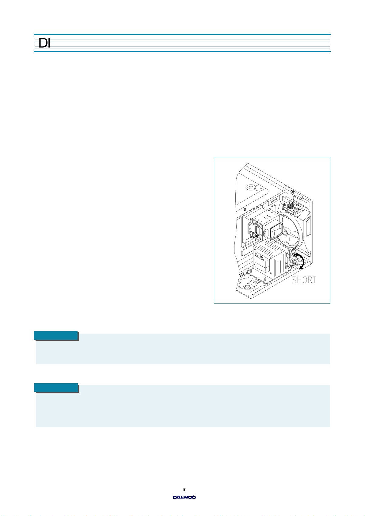
CAUTION
Service personnel should remove their watches whenever working close to or replacing the m agnetron.
WARNING
W hen servicing the appliance, need a care of touching or replacing high potential parts because of electrical shock or
exposing microwave. These parts are as follows - HV Transformer, M agnetron, HV Capacitor, HV Diode. H V Fuse.
Page 12
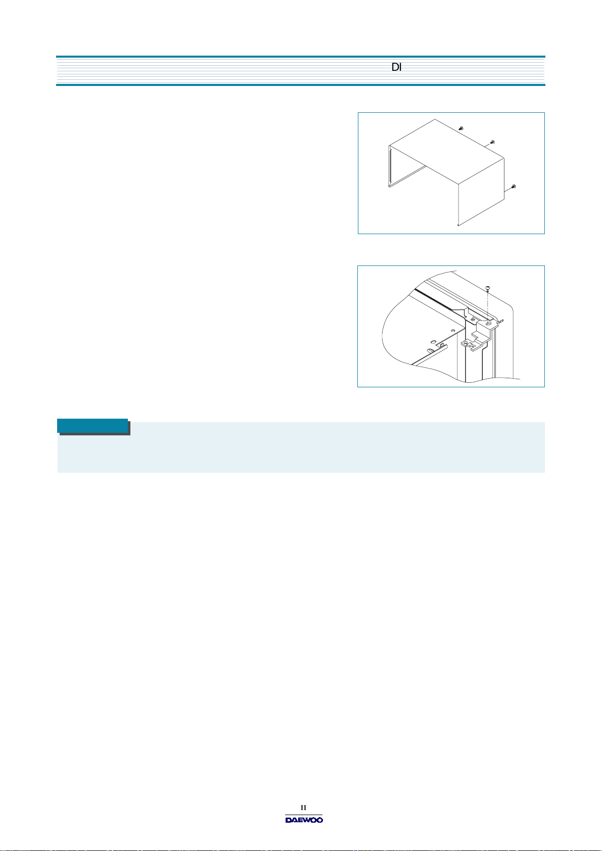
1. To remove cabinet
1) Remove three screws on cabinet back.
2) Push the cabinet backward.
2. To remove door assembly
1) Remove a screw which secure the stopper hinge top.
2) Remove the door assembly from top plate of cavity.
3) Reverse the above for reassembly.
D ISASSEMBLY AND ASSEMBLY
NOTE
After replacing the door assembly, perform a check of correct alignment with the hinge and cavity front plate.
Page 13

D ISASSE MBLY AN D A SSE M BLY
3. To remove door parts.
DOOR ASSEMBLY
KOG -372G/H0S : 3511710320
KOG -392G/HOS : 3511710750
(1) KOG-372G0S/372H0S
REF. NO PA RT CODE PART NAME DESCRIPTION QTY REMARK
A01 3517005600 BAR R IER-SCREEN *O ACRYL 1
A02 3512203820 FRA M E DO O R A BS XR -401 H-2938 1
A03 2TE20008CL DOUBLE TAPE 0.2TX8MM C LEAR 0.5ME
A04 3515204100 STOPPER HINGE *T AS KOR-63150S 1
A05 3511705500 DO O R W E LD AS KOR-61150S 1
A06 3517002800 BAR R IER-SCREEN *I POLYESTER T0.1 1
A07 3512300200 GASKET DOOR PP 1
A08 3513100730 HO OK POM 1
A09 3515101310 SPR ING HO O K HSW -3 1
(2) KOG-392G0S/392H0S
REF. NO PA RT CODE PART NAME DESCRIPTION QTY REMARK
A01 3517005700 BAR R IER-SCREEN *O ACRYL 1
A02 3512204120 FRA M E DO O R A BS XR -401 H-2938 1
A03 2TE20008CL DOUBLE TAPE 0.2TX8MM C LEAR 0.5ME
A04 3515204100 STOPPER HINGE *T AS KOR-63150S 1
A05 3511705620 DO O R W E LD AS KOR-81250S 1
A06 3517002900 BAR R IER-SCREEN *I POLYESTER T0.1 1
A07 3512300400 GASKET DOOR PP 1
A08 3513100730 HO OK POM 1
A09 3515101310 SPR ING HO O K HSW -3 1
Page 14

DISASSEM BLY AND ASSEMBLY
1) Remove the gasket door from door plate.
2) Remove the barrier screen inner from door plate.
3) Remove the door frame from door plate.
4) Remove the stopper hinge top from door plate.
5) Remove the spring and the hook.
6) Remove the barrier screen outer from door frame.
7) Reverse the above steps for reassembly.
4. Method to reduce the gap between the door seal and the oven front surface.
1) To reduce gap located on part ‘A’.
Loosen a screw on stopper hinge top, and then
push the door to contact the door seal to oven front surface.
Tighten a screw.
2) To reduce gap located on part ‘B’.
Loosen two screws on stopper hinge under, and then
push the door to contact the door seal to oven front surface.
Tighten two screws.
NOTE
A small gap m ay be acceptable if the microwave leakage does not exceed 4mW/cm2.
Page 15

D ISASSE MBLY AN D A SSE M BLY
5. To remove control panel parts.
B02
B01
B03
B04
CONTROL-PANEL ASSEMBLY
KOG -372G0S : PKCPS W BX 00
KOG -372H0S : PKCPSWB Y00
KOG -392G0S : PKCPS W BZ 00
KOG -392H0S : PKCPSWB 100
(1) KOG-372G0S/372H0S
REF.NO PART CODE PART NAME DES CRIPTION QTY REMARK
B01
3518521650
SWITCH MEMBRANE
KOG-372G0S
1
3518521660 KOG -372H 0S
B02 3516719430 CO NTR O L-PANEL ABS XR-401 H-2938 1
B03 PKM PMSB T00 PCB M AIN AS
B04 7122401211 SCREW TAPPING
KOG-371G0S
T2S TRS 4X12 M FZN
1
4
(2)KOG-392G0S/392H0S
REF.NO PART CODE PART NAME DES CRIPTION QTY REMARK
B01
3518521750
SWITCH MEMBRANE
KOG-392G0S
1
3518521760 KOG -392H 0S
B02 3516720230 CO NTR O L-PANEL ABS XR-401 H-2938 1
B03 PKM PMSB W 00 PCB M AIN AS
B04 7122401211 SCREW TAPPING
KOG-390A0S
T2S TRS 4X12 M FZN
1
4
Page 16

D ISASSEMBLY AND ASSEMBLY
1) Remove the screw which secure the control panel, push up two snap fits and draw forw ard the control panel assembly.
2) Remove four screws which secure the PCB assembly to control panel.
3) Disconnect membrane tail from the connector of the PCB assem bly.
4) Detach mem brane from the control panel.
5) Reverse the above steps for reassembly.
6. To remove high voltage capacitor.
1) Remove a screw which secure the grounding ring term inal
of the H.V.diode and the capacitor holder.
2) Remove the H.V. diode from the capacitor holder.
3) Reverse the above steps for reassembly.
High voltage circuit wiring
7. To remove magnetron.
1) Remove a screw which secure the m agnetron.
2) Remove the magnetron.
3) Reverse the above steps for reassembly.
NOTE
Never install the magnetron without the m etallic gasket plate which is packed with each magnetron to prevent
microw ave leakage. Whenever repair work is carried out on magnetron, check the m icrow ave leakage. It shall
not exceed 4mW /cm
2
for a fully assembled oven with door normally closed.
Page 17

D ISASSE MBLY AN D A SSE M BLY
8. To remove wind guide assembly.
1) Remove a screw for earthing.
2) Remove the noise filter from the wind guide.
3) Remove a screw which secure the w ind guide assembly.
4) Draw forward the wind guide assembly.
5) Pull the fan from the motor shaft.
6) Remove tw o screws w hich secure the motor shaded pole.
7) Remove the motor shaded pole.
8) Reverse the above steps for reassembly.
9. To remove H.V.transformer.
1) Remove four screws holding the H.V.transform er.
2) Remove the H.V.transform er.
3) Reverse the above steps for reassembly.
Page 18

10. To remove tray motor.
(1) Remove the coupler in the cavity.
(2) Turn the set upside down.
(3) Cut the tray motor cover part from the base plate.
(4) Remove the tray motor cover.
(5) Remove a screw which secure the tray motor.
(6) Remove the tray motor.
(7) Reverse the above steps for reassembly except for
securing the tray motor cover with screw.
D ISASSEMBLY AND ASSEMBLY
11. To remove heater assembly.
(1) Remove the three nuts.
(2) Remove the insulator heater assembly.
(3) Reverse the above steps for reassembly.
Page 19
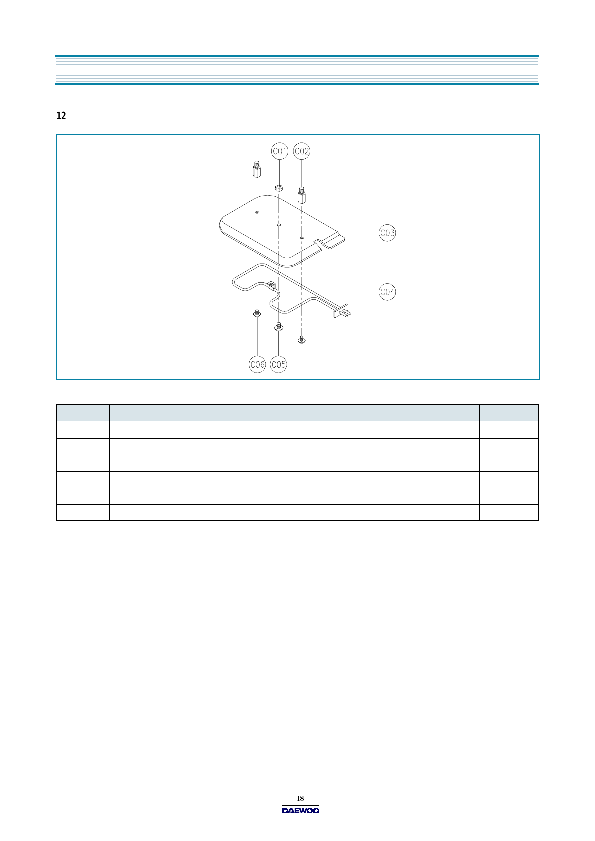
D ISASSEMBLY AND ASSEMBLY
12. To remove heater parts.
REF.NO PART CODE PAR T NAME DESCRIPTION QTY REMARK
C01 7392500008 N UT H EX 6N-2-5 SUS 1
C02 3515000600 S PACER INSULATOR *I C3771BD 2
C03 3513301100 INSULATOR HE ATER SPP T0.8 1
C04 3512803400 H EATER 230V 1000W 1R67994001 1
C05 7002500613 S CRE W M AC HINE TRS 5X6 M FCR 1
C06 7002400413 S CRE W M AC HINE TRS 4X4 M FCR 2
Page 20

INTER L OCK MECHANISM AND ADJU STM E NT
The door lock mechanism is a device which has been specially designed to completely eliminate microwave radiation when
the door is opened during operation, and thus to perfectly prevent the danger resulting from the leakage of microwave.
(1) P rima r y interlock switch
Wh e n the d o or is c l o s ed , the h oo k l o cks t h e oven d o or. If the door i s n ot closed prop erly, th e ov en will n ot o perate .
When the door is closed, the hook pushes the button of the microswitch. Then the button of the primary interlock switch
bring it under O N con dition.
(2) Secondary interlock switch and interlock monitor switch
When the door is closed, the hook pushes the lock lever dow nward. The lock lever presses the button of the interlock
monito r switch to bring it under N O condition and presses the button of the secondary interlock sw itch to bring it under
O N condit ion .
ADJUSTME NT
Interlock monitor sw itch
W hen the door is closed, the interlock m onitor switch should be changed(NO condition) before other switches are closed.
W hen the door is opened, the interlock m onitor switch should be changed(NC condition) after other switches are opened.
(3) Ad jus tment s tep s
a) Loosen the one mounting screw.
b) Adjust interlock switch assem bly position.
c) Make sure that lock lever moves smoothly after adjustment is completed.
d) Tighten completely one mounting screw.
NOTE
Microwave emission test should be performed after adjusting interlock mechanism. If the microwave em ission exceed
4mW/cm
2
, readjust interlock mechanism.
Page 21

TROUBLE SHOOTING GUIDE
Following the procedure below to check if the oven is defective or not.
1) Check earthing before trouble checking.
2) Be careful of the high voltage circuit.
3) Discharge the high voltage capacitor.
4) When checking the continuity of the switches, fuse or high voltage transform er, disconnect one lead wire from these parts
and ch ec k co ntinuity with the AC plug rem o ve d. To do otherwise may resu lt in a false reading or da mage to you r m e ter.
NOTE
W hen electric parts are checked, be sure the power cord is not inserted the wall outlet.
Check wire harness, wiring and connected of the terminals and power cord before check the parts listed below.
(TR OUB LE 1)
CONDITION
Fuse blows.
Ove n do es no t ope rate at all : any inpu ts can no t be ac cepted .
CHECK RESULT CAUSE REMEDY
Check continuity of
interlock m on itor switch
with door closed
(COM NC)
Check continuity of both
prim ary and secondary
interlock switch with door
colosed
Check continuity of prim ary
interlock sw itch contact
with door partially open
until interlock monitor switch
contact close
(COM<->NO )
Continuity
No C ontinuity
No C ontinuity
No C ontinuity
Continuity
Continuity
Malfunction
of interlock
monitor
switch
Malfunction of
interlock switch
Shorted contacts
of prima ry
interlock switch.
Replace
NOTE 1
Replace
NOTE 1
Replace
NOTE 1
Check continuity of
prim ary winding of low
voltage transform er
Disconnect high voltage
fuse and operate the unit
0 infinite
or
Ω
Approx.
150~310
(normal)
Fuse again
blows
Defective low
voltage
transformer
Defective high
voltage transformer
Replace
Replace
Page 22

TROUBLE SHOOTING GUIDE
CONDITION
Outlet has
proper voltage
Fuse does not
blow.
CHECK RESULT CAUSE REMEDY
Check continuity of
magn etron
Check continuity of
noise filter board
Check continuity of
power supply cord
No
Continuity
No
Continuity
No
Continuity
Normal
Defective
magn etron
Defective line
filter board
Open pow er
supply cord
Defective touch
control circuit
NOTE
All these switches must be replaced at the same time, please refer to “Interlock M echanism And Adjustment”.
( TROUBLE 2 )
Display shows all figures selected, but oven does not start cooking, even though desired program and time
are set and start pad is tapped.
Replace
Replace
Replace
Adjust
CONDITION
Turn table
m otor and
oven lamp do
not turn on
CHECK RESULT CAUSE REMEDY
Check continuity of
primary interlock sw itch
Check continuity of
secondary interlock and
D .O .M . sw itche s
Che ck D .C. voltage
being supplied to
RELAY (RY2) coil
No
Continuity
No
Continuity
0 V
Approx.
15 VDC
Malfunction
of primary
interlock
switch
Malfunction
of secondary
interlock and
D.O.M . switch
Defective
touch control
circuit
Faulty
contacts of
RELAY
(RY2) or open
relay coil
Adjust or
replace
Adjust or
replace
Replace
Replace
Page 23
TROUBLE SHOOTING GUIDE
(
TROUBLE 3 )
C O NDIT ION
No microwave
oscillation
N o micr o wav e o scilla t ion e ven tho ug h f a n mot o r rot a t es .
CHECK RESULT
Check continuity of high
voltage fuse
Replace high voltage fuse
Check continuity of high
voltage capacitor
te rmin a ls w ith wires
rem ov ed
Check continuity of high
vo lta g e re c tifie r in
forw ard and backward
direction with DC
megge r
No C ontinuity
Continuity
Continuity in
backward
direction
CAUSE
Defective
high voltage
transform er
Defective
high voltage
rectifier
REMEDY
Replace
Replace
Connect megger leads to
magne tron terminal and
magne tron body
Ch eck resistance of
prim ary and secondary
coil of high voltage
transformer
Check continuity of
magne tron with wires
rem oved
Check continuity of
filament term inal of high
voltage transformer
Ch eck D .C. voltage
being sup plied to
RELAY (RY1) coil
Continuity
or
0 Ω
No
Continuity
No
Continuity
0 V
Approx
15 VDC
Defective
magnetron
Defective
high voltage
transform er
Defective
magnetron
Defective
high voltage
transform er
Defective
touch control
circuit
Faulty
contacts or
RELAY
(RY1) or open
relay c o il
Replace
Replace
Replace
Replace
Replace
Replace
Page 24

TROUBLE SHOOTING GUIDE
CONDITION
Replace
control box
sub-assem bly
Replace the
Malfunction
( TROUBLE 4 )
The following visual conditions indicate a probable defective touch control circuit or membrane switch
assembly
1. In complete segm ents,
1) Segments missing.
2) Partical segments missing.
3) Digit flickering other than normal display slight
flickering.
4) “ : 0 ” does not display when power is on.
2. A distinct change in the display are not on when they
numbers is the display.
3. One or more digits in the display are not on w hen they should be.
4. Display indicates a number different from one touched.
5. Specific numbers (for example 2 or 3) will not display when the panel is touched.
6. Display does not count down or up with time cooking or clock operation.
7. Oven is programmable and cooks normally but no display shows.
M/W Def.
Grill
Combi Timer/g
8. Display obviously jumps in time w hile counting down.
9. Display counts dow n noticeably too fast while cooking.
10. Display does not show the tim e of day when clear pad is touched.
11. O ven lamp and turntable motor do not stop although cooking is finished. Check if the RELAY 2 contacts close if they are
close, replace touch control circuit.
CHECK RESULT CAUSE REMEDY
Display does
not show
programm ing
at all, even if
keyboard is
touched.
Check each pad for
continuity of the
mem brane keyboard
for the following
keyboard check
procedure
Normal
Abnormal
of touch
control circuit
of control box
sub-assem bly
Malfunction of
the membrane
keyboard
membrane
keyboard
NOTE
Before following the particular steps listed above in the trouble shooting guide for the membrane keyboard’s, failure,
please check for the continuity of each wire-harness between the mem brane keyboard and P.C.B. assembly.
Page 25
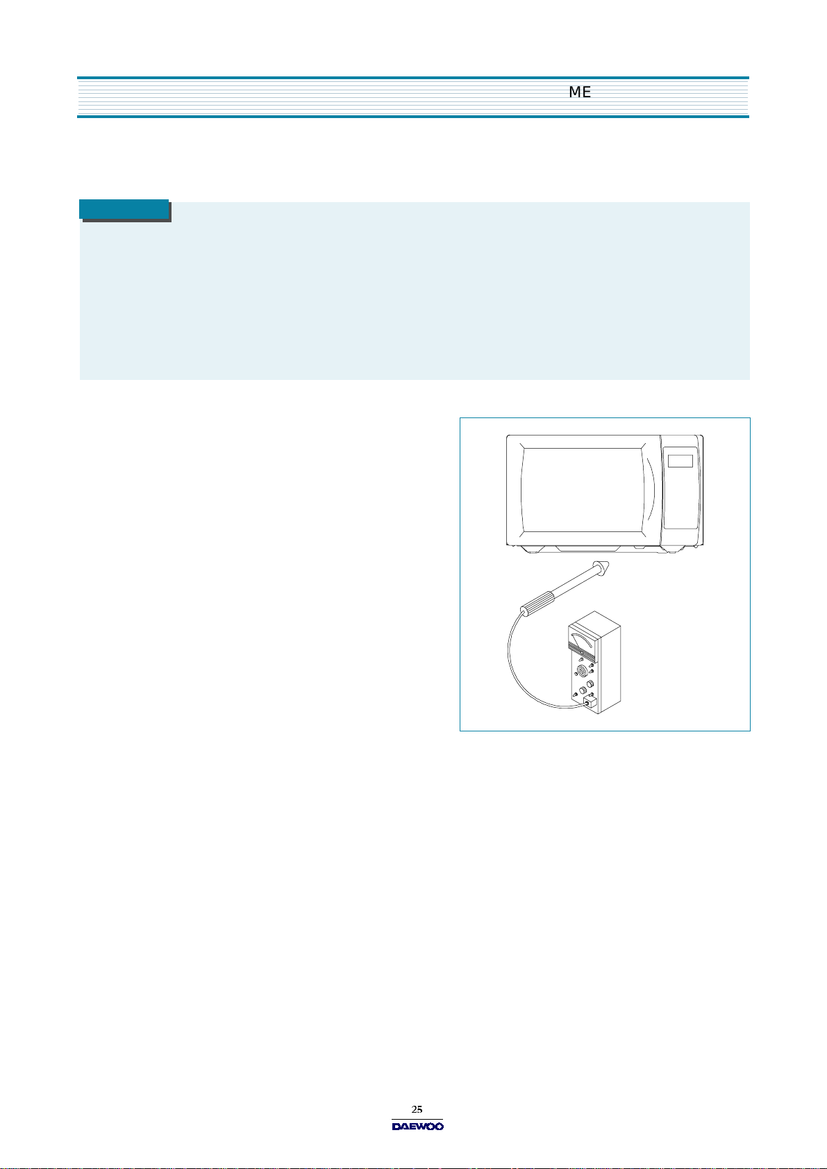
ME ASUREME NT AND TEST
1. MEASUREMENT OF THE MICROWAVE POWER OUTPUT
Microwave output power can be checked by indirectly measuring the temperature rise of a certain amount of water exposed
to the m icrowave as directed below.
PROCEDURE
1. Microwave power output measurement is m ade w ith the m icrowave oven supplied at rated voltage and operated at its
maximum m icrowave power setting with a load of 1000 ± 5cc of potable water.
2. T h e w a te r is co nta in ed in a cy lin d ric a l b o ro s ilic a te g la s s v e s se l h a v in g a max imu m mate r ia l th ic kn e s s of 3 m m and an
outside diameter of approximately 190 m m.
3. The oven and the empty vessel are at ambient temperature prior to the start of the test. The initial temperature of the
water is 10 ± 2 °C (50 ± 3.6 ° F). It is measured immediately before the water is added to the vessel. After addition of
the water to the vessel, the load is imm ediately placed on the center of the shelf, which is in the low est normal position.
4. Microwave power is switched on.
5. Heating tim e should be exactly A seconds.
(Refer to table as following)
Heating time is measured while the
microw ave generator is operating at
full power. The filament heat-up time
for magnetron is not included.
6. The initial and final tem perature of w ater is selected
so that the maximum difference betwe en the ambient
and final water temperature is 5K.
7. The microwave power output P in watts is calculated
from the follow ing form ula:
P = 4187 X T
T is difference between initial and ending temperature.
t is the heating time.
The power measured should be B (Refer to SPEC IFICATIONS) W ± 10.0 %.
CAUTION
1. Water load should be m easured exactly to 1 liters.
2. Input pow er voltage should be exactly specified voltage (Refer to SPEC IFICATIONS).
3. Ambient tem perature should be 20
Heating time for power output:
A (second) 70 64 60 56 52 49 47 44 42 40 38
B (W) 600 650 700 750 800 850 900 950 1000 1050 1100
± 2°C (68 ± 3.6 °F)
Page 26
MEASUR E MENT AND TE ST
2. MICROWAVE RADIATION TEST
CAUTION
1. Make sure to check the microwave leakage before and after repair of adjustment.
2. Always start measuring of an unknown field to assure safety for operating personnel from microwave energy.
3. Do not place your hands into any suspected microwave radiation field unless the safe density level is known.
4. Care should be taken not to place the eyes in direct line with the source of m icrowave energy.
5. Slowly approach the unit under test until the radiometer reads an appreciable microwave leakage from the unit
under the test.
PROCEDURE
1. Prepare Microw ave Energy Survey Meter,
600cc glass beaker, and glass thermometer
100°C (212°F ).
2. Pour 275cc ±15cc of tap w ater initially at 20 ± 5 °C
(68 ± 9°F) in the 600 cc glass beaker with an inside
diameter of approx. 95 mm(3.5 in.).
3. Place it at the center of the tray and set it in a cavity.
4. Close the door and operate the oven.
5. Measure the leakage by using Microw ave E nergy
Survey Meter with dual ranges, set to 2450MHz.
1) Measured radiation leakage must not exceed the
value prescribed below. Leakage for a fully assem bled
2
oven with door normally closed must be less than 4mW /cm
.
2) When measuring the leakage, always use the 5 cm (2 in.) space cone with probe. Hold the probe perpendicular to the
cabinet and door. Place the space cone of the probe on the door, cabinet, door seem , door viewing screen, the exhau st
air vents and the suction air vents.
3) Measuring should be in a counter-clockwise direction at a rate of 1 in./sec. If the leakage of the cabinet door seem is
unknown, m ove the probe more slowly.
4) When measuring near a corner of the door, keep the probe perpendicular to the areas m aking sure the probe end at
the base of the cone does not get closer than 2 in. from any metal. If it does not, erroneous reading may result.
Page 27

MEASUR E MENT AND TE ST
3. COMPONENT TEST PROCEDURE
High voltage is present at the high voltage term inal of the high voltage transform er during any cooking cycle.
It is neither necessary nor advisable to attempt m easurement of the high voltage.
Before touching any oven components or wiring, always unplug the oven from its power source and discharge the capacitor.
1. High voltage transformer
1) Remove connections from the transformer terminals and check continuity.
2) Normal readings should be as follows :
Secondary w inding ... Approx. 110 ±10%
once the capacitor charged.
Filament winding ... A pprox. 0
Prim ary winding ... Approx. 1
2. High voltage capacitor
1) Check continuity of capacitor with meter on the highest O H M scale.
2) A norma l capacito r will s ho w cont inu i ty fo r a sh or t t ime, and then indicate 10M
3) A shorted capacitor will show continuous continuity.
4) An open capacitor will show constant 10M.
5) Resistance between each term inal and chassis should be infinite.
3. High voltage diode
1) Isolate the diode from the circuit by disconnecting the leads.
2) With the ohmmeter set on the highest resistance scale measure the resistance across the diode terminals. Reverse
the meter leads and again observe the resistance reading. M eter with 6V, 9V or higher voltage batteries should be
used to check the front-back resistance of the diode, otherwise an infinite resistance may be read in both directions. A
normal diode's resistance will be infinite in one direction and several hundred k
in the other direction.
4. Magnetron
For com plete magnetron diagnosis, refer to “Measurement of the Microwave Power O utput. " Continuity checks can only
indicate and open filament or a shorted magnetron. To diagnose for an open filament or a shorted magnetron,
1) Isolate magnetron from the circuit by disconnecting the leads.
2) A continuity check across magnetron filament terminals should indicate 0.1
or less.
3) A continuity check between each filam ent terminal and magnetron case should read open.
5. Fuse
If the fuse in the primary and monitor switch circuit is blown when the door is opened, check the primary and m onitor
switch before replacing the blown fuse. In case the fuse is blown by an improper switch operation, replace the defective
switch and fuse at the same time. Replace just the fuse if the switches operate normally.
Page 28

WIRING DIAGR AM
Page 29

PRINTED CIRCUIT BOARD
1. CIRCUIT CHECK PROCEDURE
1. Low voltage transformer check
The low voltage transformer is located on the P.C .B.
Measuring condition: Input voltage: 230 V / Frequency: 50Hz
Terminal Voltage LOAD NO LO AD
4 - 7 AC 12.6 V AC 14.7 V
NOTE
1. Refer to Circuit Diagram (point 4).
2. Secondary side voltage of the low voltage transformer changes in proportion to fluctuation of power source voltage.
3. T he allowable tolerance of the secondary voltage is within 5% of nominal voltage.
2. Voltage Check
- Key check point
NO CHECK POINT REMARK
1 IC1 PIN 2,21,30,34 -5VDC
2IC1 PIN 35
T : 20ms ( 50Hz)
3 IC1 PIN 31 OR 32
T : 250 ns( 4M Hz )
- Check method
NO MEASURE POINT WAVE FORM REMEDY REMARK
1 MP1 DC -5V± 0.25V Replace V L1, EC1 NO LOA D
2 MP2 DC -12V± 2.0V Replace E C2, D12,13,14 NO LO AD
NOTE
Each measure point must be measured with GND points.
Page 30
PRINTED CIRCUIT BOARD
MP1
MP2
Measure Poin t
Page 31

PRINTED CIRCUIT BOARD
3. When there is no microwave oscillation
1) When touching
START
pad, oven lamp does not turn on.
Fan motor do not ro tate, but cook indicator in display comes on.
Cause :
RELAY 2
does not operate. ref e r to Circuit Di a gr a m ( P oint 3)
- Check method
STATE
2) When touching
RELAY 2
RELAY 2
START
P OINT
ON - 5VDC GND
OFF GND - 12VDC
pad, oven lamp turns on.
A B
Fan motor and turntable rotate and cook indicator in display comes on.
Cause :
RELAY 1
does not operate. ref e r to Circuit Di a gr a m ( P oint 2 )
- Check method
STATE
RELAY 1
RELAY 1
POINT
O N -5V DC GN D
OFF GND -12VDC
A B
4. When there is no grill oscillation.
Cause :RELAY3 does not operate refer to circuit D iagram (point 6)
- Check method
POINT
STATE
RELAY3 ON -5VDC GND
RELAY3 OFF GND -12VDC
A B
5. When the door is opened during operation, the count down timer does not stop.
refer to Circuit Diagram ( Point 1 )
- Check method
POINT
STATE
1) DOOR OPEN OPEN -5VDC
2) DOOR CLOSED CLOSE GND
CHECK NO METHOD REMEDY
1
Check the stage(ON,OFF) of the door open m onitor switch by resistance
me as urement.
A B
Replace door open monitor switch.
6. When the digital clock does not operate properly.
refer to Circuit D iagram ( Point 5 )
POINT WAVE FORM
A T: 20 ms(50Hz)
If clock does not keep exact time, you must check resistor R15,16, zener diodeZ D1.
Page 32

2. P.C.B. CIRCUIT DIAGRAM
PRINTED CIRCUIT BOARD
Page 33

PRINTED CIRCUIT BOARD
3. P.C.B. LOCATION NO
(1) KOG-372G0S/372H0S
NO NAME SYMBOL SPECIFICATION PART CODE Q'TY
1 B UZZER B Z1 BM-20K 3515600100 1
2 C ARR AY CA1 7P(6) 102 M 50V CN6XB-102M 1
3 C APACITOR ELEC EC1 16V R SS 100uF CEXF1C101V 1
4 C APACITOR ELEC EC2 25V R SS 1000uF CEXF1E102V 1
5 C ON NE CTOR WAF ER CN1 YW396-02AV 3519150520 1
6 C ON NE CTOR WAF ER CN2 YW396-05AV 3519150510 1
7 C ON NE CTOR WAF ER CN3 FCZ254-11 441M367160 1
8 D IODE REC TIFY D1~6,8~12 1N4148 D ZN 4148--- 11
9 D IODE R ECTIFY D13,14 1N4002A DZ N4002A-- 2
10 DIOD E ZENER ZD1 MTZ 5.1VB 1/2W DZTZ5R1B-- 1
11 DIODE ZENER ZD2 MTZ 3.9VB 1/2W DZTZ3R9B-- 1
12 LED DISPLAY DP1 DDG -631H DDDG631H-- 1
13 PCB MA IN M158 81.5X139.9 3514315410 1
14 R ARRAY RA1 7P(6) 1/8 100K J RA-87X104J 1
15 RESISTOR R1~R7 1/6W 330 5% R D-AZ331J- 7
16 RESISTOR R8,10,12,14,22 1/6W 1K 5% RD-AZ102J- 5
17 RESISTOR R11,20,21 1/6W 100K 5% R D -AZ104J- 3
18 RESISTOR R13 1/6W 100 5% R D-AZ101J- 1
19 RESISTOR R15~17 1/6W 10K 5% RD-AZ103J- 3
20 RESISTOR R18 1/6W 1M 5% R D-AZ105J- 1
21 RESISTOR R19 1/4W 51 5% RD-4Z510J- 1
22 REGULATOR VL1 M C7905C 1MC 7905C-- 1
23 TRANSISTOR Q1~5,8~11 KRA-102M TZRA102M-- 9
24 TRANSISTOR Q6 KTA-1270Y TZTA1270Y- 1
25 TRANS POW ER LVT1 DMR-631FS 5EPV035303 1
26 W IRE COPPER J1-J21 1/0.52 TIN CO ATING 85801052GY 21
27 W IRE COPPER SJ4 1/0.52 TIN CO ATING 85801052GY 1
28 IC MICOM IC1 TMP47C440BN-NF94 13GS371G H0 1
29 R ESONATO R CERA CR1 KBR-4.0MSTF 5PKBR40MKS 1
30 SW RE LAY RY1, RY3 G 5G-1A DC12V 5SC0101121 2
31 SW RE LAY RY2 G 5B-1 DC12V 5SC0101110 1
32 CAPACITOR CER A C6 102 50V Z AXIAL CCZB1H102K 1
33 CAPACITOR CER A C1~5,C7 104 50V Z AXIAL CC ZF1H104Z 6
Page 34

PRINTED CIRCUIT BOARD
(2) KOG-392G0S/392HOS
NO NAME SYMBOL SPECIFICATION PART CODE Q'TY
1 B UZZER B Z1 BM-20K 3515600100 1
2 C ARR AY CA1 7P(6) 102 M 50V CN6XB-102M 1
3 C APACITOR ELEC EC1 16V R SS 100uF CEXF1C101V 1
4 C APACITOR ELEC EC2 25V R SS 1000uF CEXF1E102V 1
5 C ON NE CTOR WAF ER CN1 YW396-02AV 3519150520 1
6 C ON NE CTOR WAF ER CN2 YW396-05AV 3519150510 1
7 C ON NE CTOR WAF ER CN3 FCZ254-11 441M367160 1
8 D IODE REC TIFY D1~6,8~12 1N4148 D ZN 4148--- 11
9 D IODE R ECTIFY D13,14 1N4002A DZ N4002A-- 2
10 DIOD E ZENER ZD1 MTZ 5.1VB 1/2W DZTZ5R1B-- 1
11 DIODE ZENER ZD2 MTZ 3.9VB 1/2W DZTZ3R9B-- 1
12 LED DISPLAY DP1 DDG -631H DDDG631H-- 1
13 PCB MA IN M158 81.5X139.9 3514315410 1
14 R ARRAY RA1 7P(6) 1/8 100K J RA-87X104J 1
15 RESISTOR R1~R7 1/6W 330 5% R D-AZ331J- 7
16 RESISTOR R8,10,12,14,22 1/6W 1K 5% RD-AZ102J- 5
17 RESISTOR R11,20,21 1/6W 100K 5% R D -AZ104J- 3
18 RESISTOR R13 1/6W 100 5% R D-AZ101J- 1
19 RESISTOR R15~17 1/6W 10K 5% RD-AZ103J- 3
20 RESISTOR R18 1/6W 1M 5% R D-AZ105J- 1
21 RESISTOR R19 1/4W 51 5% RD-4Z510J- 1
22 REGULATOR VL1 M C7905C 1MC 7905C-- 1
23 TRANSISTOR Q1~5,8~11 KRA-102M TZRA102M-- 9
24 TRANSISTOR Q6 KTA-1270Y TZTA1270Y- 1
25 TRANS POW ER LVT1 DMR-631FS 5EPV035303 1
26 W IRE COPPER J1-J21 1/0.52 TIN CO ATING 85801052GY 21
27 W IRE COPPER SJ1, SJ4 1/0.52 TIN COATING 85801052G Y 2
28 IC MICOM IC1 TMP47C440BN-NF94 13GS371G H0 1
29 R ESONATO R CERA CR1 KBR-4.0MSTF 5PKBR40MKS 1
30 SW RE LAY RY1, RY3 G 5G-1A DC12V 5SC0101121 2
31 SW RE LAY RY2 G 5B-1 DC12V 5SC0101110 1
32 CAPACITOR CER A C6 102 50V Z AXIAL CCZB1H102K 1
33 CAPACITOR CER A C1~5,C7 104 50V Z AXIAL CC ZF1H104Z 6
Page 35

EXPLODED VIEW AND PARTS LIST
1. DOOR ASSEMBLY
Refer to Disassembly and assembly.
2. CONTROL PANEL ASSEMBLY
Refer to Disassembly and assembly.
3. TOTAL ASSEMBLY
Page 36

EXPLODED VIEW AND PARTS LIST
(1) KOG-372G0S/372H0S
REF NO PART CODE PART NAME DESCRIPTIO N Q'TY
A00 D O OR A S Refer to disassembly and assembly 1
B00 C O NT RO L PANE L AS Refer to disassembly and assem bly 1
F01 3510801310 CABINET PCM T0.5 GE 1
F02 7112401011 SCREW TAPPING T1 TRS 4*10 MFZN 3
F03 3516109010 CAVITY WELD AS C AVITY W ELD AS 1
3516109610 CAVITY JOINT AS CAVITY JOINT AS 1
F04 7392500008 NUT H EX 6N-2-5 SUS 2
F05 7122401211 SCRE W TAPPING T2S TR S 4*12 MFZN 1
F06 3518904500 THERM O STAT OFF : 100 ON : 90 HN #187 1
F07 7121300611 SCRE W TAPPING T2S PAN 3X6 M FZN 1
F08 7122401211 SCRE W TAPPING T2S TR S 4*12 MFZN 1
F09 7112401011 SCREW TAPPING T1 TRS 4*10 MFZN 2
F10 35113A 5QJ5 C O RD P O WE R AS 3X1.5 80X80 120-RTML 1.4M 1
F11 4413A90012 CLA MP POWE R CO R D N YLON 66 1
F12 7112401011 SCREW TAPPING T1 TRS 4*10 MFZN 1
F13 7122401211 SCRE W TAPPING T2S TR S 4*12 MFZN 1
F14 7112401011 SCREW TAPPING T1 TRS 4X10 MF ZN 1
F15 7S627W50X1 NUT HEX NUT FLANGE M5X0.8P MFZN 1
F16 4414A25110 FUSE 250V 15A 65TS 1
4414A25100 FU SE 250V 15A M D A15 1
F17 3518606100 NO ISE-FILTER DW LF-M13 1
F18 7124402511 SC REW TAPPING T2S RND 4X 25 MFZ N 2
F19 3963513100 M O TOR SH AD ED POLE 230V 17W O E M-10DW C2-A07 1
3963512310 MO TO R SH ADED PO LE 230V 20W M W 10CA -M02 1
F20 3512517000 G UIDE W IND PP 1
F21 3511800300 FAN PP+30% GLA SS 1
F22 3518002200 M AGN ET RON 2M 218H(MF)I 1
F23 3516004000 SPECIAL SCREW T2 BOLT FLANGE 5X12 DACRO 1
F24 7272400811 SC REW TAPTITE T T3 TRS 4*8 MFZN 1
F25 3513003200 HO LDER HV C APACITOR SEC C T0.6 1
F26 3518302200 CA PACITOR H V 2100VAC 0.98uF #187 1
F27 3518400400 DIODE HV HVR-1X-3AB 12KV #187 1
F28 3518701100 FU SE HV 5KV 0.55A HV-41A55-02 1
F29 3518113700 TR ANS H V DY-N80S0-63T 1
F30 3516003700 SPECIAL SCREW TT3 HEX 4X8 FLG M FZN 4
F31 3510311700 BASE SBHG T0.8 1
F32 7112401011 SCREW TAPPING T1 TRS 4*10 MFZN 5
Page 37
EXPLODED VIEW AND PARTS LIST
REF NO PART CODE PART NAME DESCRIPTIO N Q'TY
F33 3512100900 FO OT PP DASF-130 2
F34 7272400811 SC REW TAPTITE T T3 TRS 4X8 M FZN 1
F35 3515201101 STO PPER H INGE *U SCP-1 T2.5 1
F36 4415A17352 SW M ICRO VP-533A-OF SPNO #187 200G 1
F37 4415A66910 SW M ICRO VP-531A-OF/SZM-V16-FA-61 1
F38 4415A17352 SW M ICRO VP-533A-OF SPNO #187 200G 2
F39 3513702600 LEV ER LO CK POM 1
F40 3513811710 LO CK POM 1
F41 3513601600 LAM P BL 240V 25W T 25 C7A H187 1
F42 7121400611 SC REW TAPPING T2S PAN 4X6 MFZN 1
F43 3966310100 M O TOR SY NC RO 220V 2.5W GM -16-24FD12 1
3966310110 M O TOR SY NCR O 220V 2.5W M2LJ49ZT52 1
F44 3518905300 TH ERM O STAT OFF:75 ON:65 H #187 NB 1
F45 3513003400 HO LDE R TH ER MO STAT PBT 1
F46 7272400811 SC REW TAPTITE T T3 TRS 4X8 M FZN 1
F47 3511405100 CO VER WAVE G UIDE MICA T0.5 1
F48 4078502031 BU TTON LOCK ING PP HO N AM A353 2
F49 3517400620 CO UP LER XARE C 1
F50 3514700710 RO LLER TEFLON 3
F51 3512517300 G UIDE RO LLER PP 5113M F6 A353B 1
F52 3517203600 TR AY G LASS 1
F53 3517206900 TR AY RACK AS KO G-37150S 110MM 1
Page 38
EXPLODED VIEW AND PARTS LIST
(2) KOG-392G0S/392H0S
REF NO PART CODE PART NAME DESCRIPTIO N Q'TY
A00 D O OR A S Refer to disassembly and assembly 1
B00 C O NT RO L PANE L AS Refer to disassembly and assem bly 1
F01 3510801400 CA BINET PCM T0.6 1
F02 7112401011 SCREW TAPPING T1 TRS 4*10 MFZN 3
F03 3516109210 CAVITY WELD A S CAVITY WELD A S 1
3516109710 CAVITY JOINT AS CAVITY JOINT AS 1
F04 7392500008 NU T HE X 6N-2-5 SUS 2
F05 7122401211 SC REW TAPPING T2S TRS 4*12 MFZN 1
F06 3518904500 TH ERM O STAT OFF : 100 ON : 90 HN #187 1
F07 7121300611 SC REW TAPPING T2S PAN 3X6 MFZN 1
F08 7122401211 SC REW TAPPING T2S TRS 4*12 MFZN 1
F09 7112401011 SCREW TAPPING T1 TRS 4*10 MFZN 2
F10 35113A 5QJ5 C O RD P O WE R AS 3X1.5 80X80 120-RTML 1.4M 1
F11 4413A90012 CLA MP POWE R CO R D N YLON 66 1
F12 7112401011 SCREW TAPPING T1 TRS 4*10 MFZN 1
F13 7122401211 SC REW TAPPING T2S TRS 4*12 MFZN 1
F14 7112401011 SCREW TAPPING T1 TRS 4X10 MF ZN 1
F15 7S627W50X1 NUT HEX NUT FLANGE M5X0.8P MFZN 1
F16 4414A25110 FUSE 250V 15A 65TS 1
4414A25100 FU SE 250V 15A M D A15 1
F17 3518606100 NO ISE-FILTER DW LF-M13 1
F18 7124402511 SC REW TAPPING T2S RND 4X 25 MFZ N 2
F19 3963513100 M O TOR SH AD ED POLE 230V 17W O E M-10DW C2-A07 1
3963512310 MO TO R SH ADED PO LE 230V 20W M W 10CA -M02 1
F20 3512517000 G UIDE W IND PP 1
F21 3511800300 FAN PP+30% GLA SS 1
F22 3518002200 M AGN ET RON 2M 218H(MF)I 1
F23 3516004000 SPECIAL SCREW T2 BOLT FLANGE 5X12 DACRO 1
F24 7272400811 SC REW TAPTITE T T3 TRS 4*8 MFZN 1
F25 3513003200 HO LDER HV C APACITOR SEC C T0.6 1
F26 3518302200 CA PACITOR H V 2100VAC 0.98uF #187 1
F27 3518400400 DIODE HV HVR-1X-3AB 12KV #187 1
F28 3518701100 FU SE HV 5KV 0.55A HV-41A55-02 1
F29 3518114800 TR ANS H V DY-N90S0-86T B 1
F30 3516003700 SPECIAL SCREW TT3 HEX 4X8 FLG M FZN 4
F31 3510311900 BASE SBHG T0.8 1
F32 7112401011 SCREW TAPPING T1 TRS 4*10 MFZN 5
Page 39

EXPLODED VIEW AND PARTS LIST
REF NO PART CODE PART NAME DESCRIPTIO N Q'TY
F33 3512100900 FO OT PP DASF-130 2
F34 7272400811 SC REW TAPTITE T T3 TRS 4X8 M FZN 1
F35 3515201101 STO PPER H INGE *U SCP-1 T2.5 1
F36 4415A17352 SW M ICRO VP-533A-OF SPNO #187 200G 1
F37 4415A66910 SW M ICRO VP-531A-OF/SZM-V16-FA-61 1
F38 4415A17352 SW M ICRO VP-533A-OF SPNO #187 200G 2
F39 3513702600 LEV ER LO CK POM 1
F40 3513811710 LO CK POM 1
F41 3513601600 LAM P BL 240V 25W T 25 C7A H187 1
F42 7121400611 SC REW TAPPING T2S PAN 4X6 MFZN 1
F43 3966310100 M O TOR SY NC RO 220V 2.5W GM -16-24FD12 1
3966310110 M O TOR SY NCR O 220V 2.5W M2LJ49ZT52 1
F44 3518905300 TH ERM O STAT OFF:75 ON:65 H #187 NB 1
F45 3513003400 HO LDE R TH ER MO STAT PBT 1
F46 7272400811 SC REW TAPTITE T T3 TRS 4X8 M FZN 1
F47 3511405100 CO VER WAVE G UIDE MICA T0.5 1
F48 4078502031 BU TTON LOCK ING PP HO N AM A353 2
F49 4418D10032 C OUP LER PPS 1
F50 3514700900 RO LLER TEFLON 3
F51 3512509200 G UIDE RO LLER PP 1
F52 3517203500 TR AY G LASS 1
F53 3517206900 TRAY RACK AS K OG -37150S 110M M 1
 Loading...