

Page 1
Refrigerator
S/M No: FRSU20IA01
July . 2005
4
Caution
: In this Manual, some parts can be changed for improving, their
performance without notice in the parts list. So, if you need the
latest parts information,please refer to PPL(Parts Price List) in
Service Information Center
Page 2
1
C O N T E N T S
1. WARNINGS AND PRECAUTIONS FOR SAFETY --------------------------------------------
2. EXTERNAN VIEW
2-1. External Size ----------------------------------------------------------------------------------------2-2. Name of Each Parts ---------------------------------------------------------------------------------
3. SPECIFICATION ---------------------------------------------------------------------------------------
4. OPERATION AND FUNCTIONS -------------------------------------------------------------------
5. CIRCUIT OPERATION
5-1. Power Circuit Diagram ----------------------------------------------------------------------------5-2. Function of Each Sensor -------------------------------------------------------------------------5-3. Relay Function --------------------------------------------------------------------------------------5-4. Fan Function -----------------------------------------------------------------------------------------
6. DIAGRAM
6-1. Wiring Diagram --------------------------------------------------------------------------------------6-2. Circuit Diagram of Main PCB ---------------------------------------------------------------------
7. COMPONENT LOCATE VIEW ---------------------------------------------------------------------
8. HOW TO CHECK EACH PARTS
8-1. Hose Ice Maker Tube ------------------------------------------------------------------------------8-2. Bracket Geared Motor -----------------------------------------------------------------------------8-3. Dispenser Micro Switch ---------------------------------------------------------------------------8-4. Dispenser Solenoid Valve ------------------------------------------------------------------------8-5. Main PCB ---------------------------------------------------------------------------------------------8-6. Ice Maker ----------------------------------------------------------------------------------------------
9. TROUBLE DIAGNOSIS
9-1. Power Failure ----------------------------------------------------------------------------------------9-2. Freezer Compartment -----------------------------------------------------------------------------9-3. Refrigerator Compartment ------------------------------------------------------------------------9-4. Operation Noise of Refrigerator -----------------------------------------------------------------9-5. Door -----------------------------------------------------------------------------------------------------
10. COOLING CYCLE HEAVY REPAIR
10-1. Summary of Heavy Repair ----------------------------------------------------------------------10-2. Precaution during Heavy Repair --------------------------------------------------------------10-3. Practical Work for Heavy Repair --------------------------------------------------------------10-4. Standard Regulations for Heavy Repair -----------------------------------------------------10-5. Brazing Reference Drawing ---------------------------------------------------------------------
11. INSTALLATION GUIDE
11-1. Installation Preparation --------------------------------------------------------------------------11-2. If the Refrigerator can not enter the Door ---------------------------------------------------11-3. Refrigerator Leveling & Door Adjustment ---------------------------------------------------11-4. Water Line Installation ---------------------------------------------------------------------------11-5. Dispenser Water Flow ----------------------------------------------------------------------------
12. EXPLODED VIEW & PARTS LIST
12-1. FRS(N)-U20IA -------------------------------------------------------------------------------------12-2. FRS(N)-U20DA ------------------------------------------------------------------------------------12-3. FRS(N)-U20EA ------------------------------------------------------------------------------------12-4. FRS(N)-U20FA ------------------------------------------------------------------------------------12-4. FRS(N)-U20GA -------------------------------------------------------------------------------------
2
3
6
11
14
34
35
37
39
40
42
46
48
49
50
51
52
53
56
57
63
67
74
75
76
77
79
80
81
82
84
85
87
88
98
109
120
131
Page 3
2
Please observe the following safety precautions in order to use safely and correctly the refrigerator
and to prevent accident and danger during repair.
1. Be care of an electric shock. Disconnect power cord from wall outlet and wait for more than
three minutes before replacing PCB parts.
Shut off the power whenever replacing and repairing electric components.
2. When connecting power cord, please wait for more than five minutes after power cord was
disconnected from the wall outlet.
3. Please check if the power plug is pressed down by the refrigerator against the wall.
If the power plug was damaged, it may cause fire or electric shock.
4. If the wall outlet is over loaded, it may cause fire.
Please use its own individual electrical outlet for the refrigerator.
5. Please make sure the outlet is properly earthed, particularly in wet or damp area.
6. Use standard electrical components when replacing them.
7. Make sure the hook is correctly engaged.
Remove dust and foreign materials from the housing and connecting parts.
8. Do not fray, damage, machine, heavily bend, pull out or twist the power cord.
9. Please check the evidence of moisture intrusion in the electrical components.
Replace the parts or mask it with insulation tapes if moisture intrusion was confirmed.
10. Do not touch the icemaker with hands or tools to confirm the operation of geared motor.
11. Do not let the customers repair, disassemble and reconstruct the refrigerator for themselves.
It may cause accident, electric shock, or fire.
12. Do not store flammable materials such as ether, benzene, alcohol, chemicals, gas, or
medicine in the refrigerator.
13. Do not put flower vase, cup, cosmetics, chemicals, etc., or container with full of water
on the top of the refrigerator.
14. Do not put glass bottles with full of water into the freezer.
The contents shall freeze and break the glass bottles.
15. When you scrap the refrigerator, please disconnect the door gasket first and scrap it
where children are not accessible.
1. WARNINGS AND PRECAUTIONS FOR SAFETY
Page 4
3
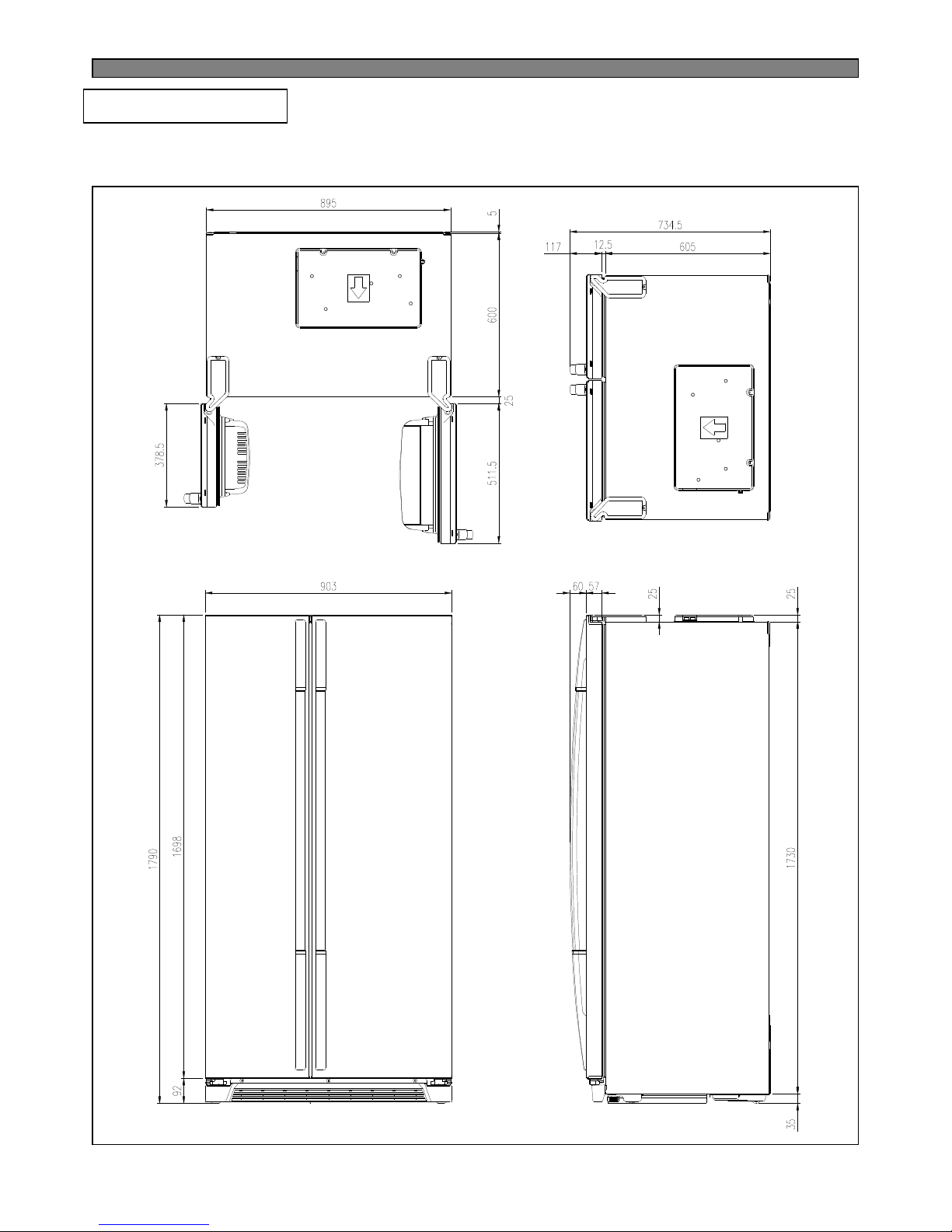
2. EXTERNAL VIEWS
2-1. External Size
■ FRS(N)-U20IA
Page 5
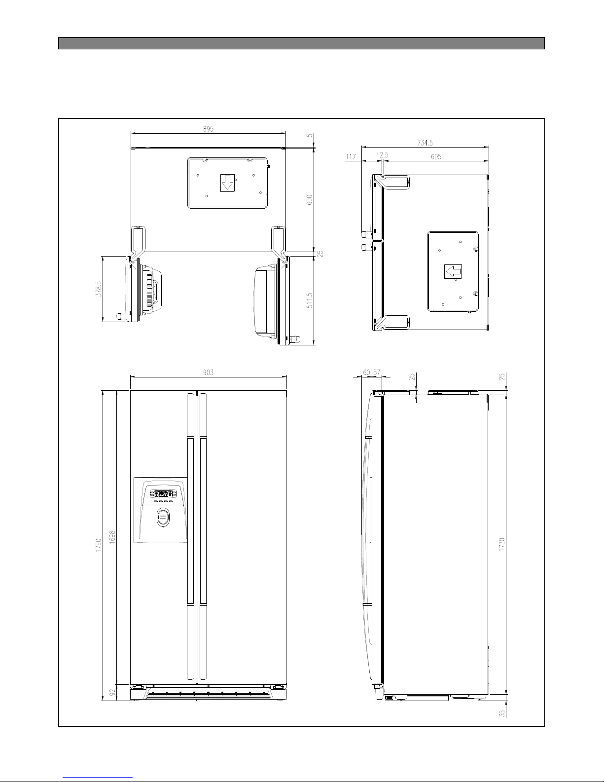
4
■ FRS(N)-U20DA / FRS(N)-U20EA
Page 6
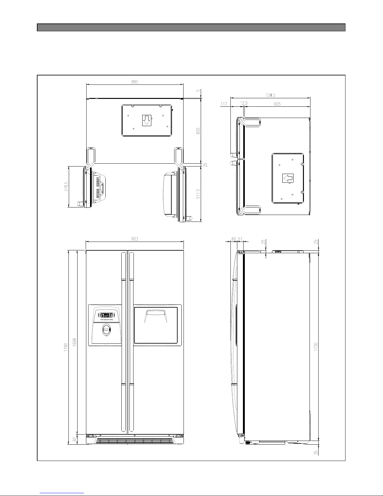
5
■ FRS(N)-U20FA / FRS(N)-U20GA
Page 7
6
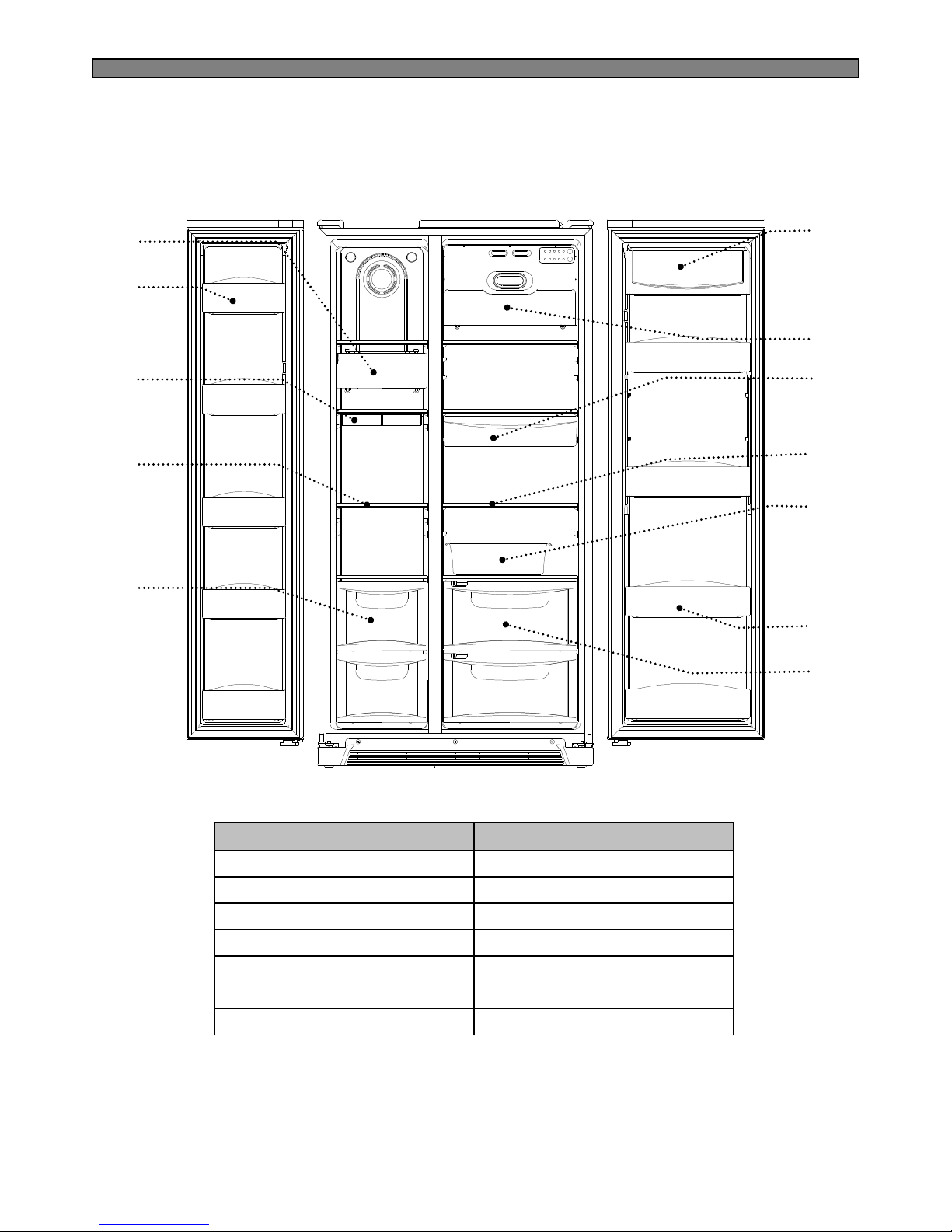
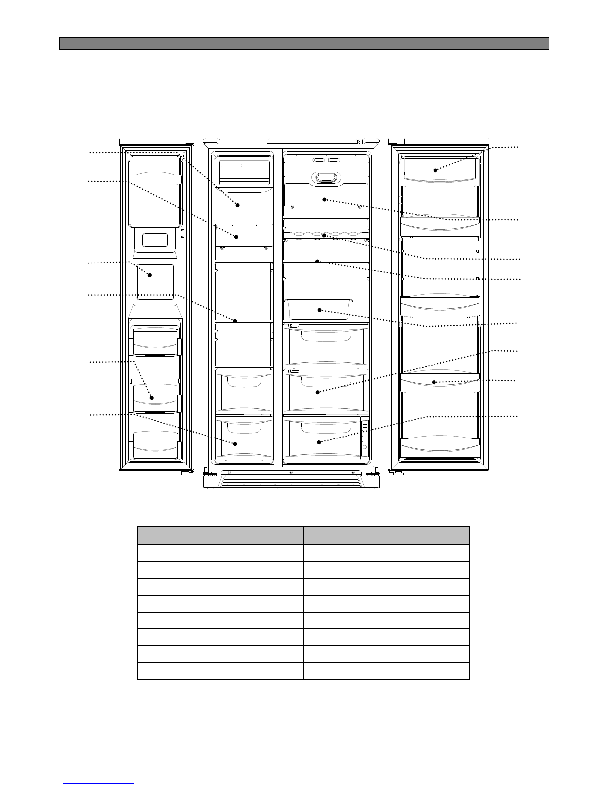
12. Refrigerator case
11. Refrigerator pocket
10. Movable Egg case5. Freezer case
9. Refrigerator shelf4. Freezer shelf
8. Chilled case3. Ice tray
7. Refrigerator light2. Freezer pocket
6. Dairy pocket1. Freezer light
Refrigerator Compartment
Freezer Compartment
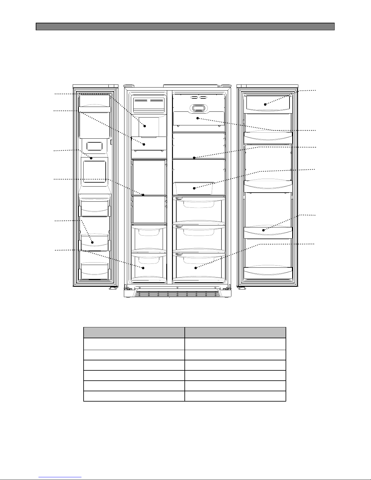
2-2. Name of Each Parts
■ FRS(N)-U20IA
1
2
4
3
5
7
8
9
10
11
6
12
Page 8
7
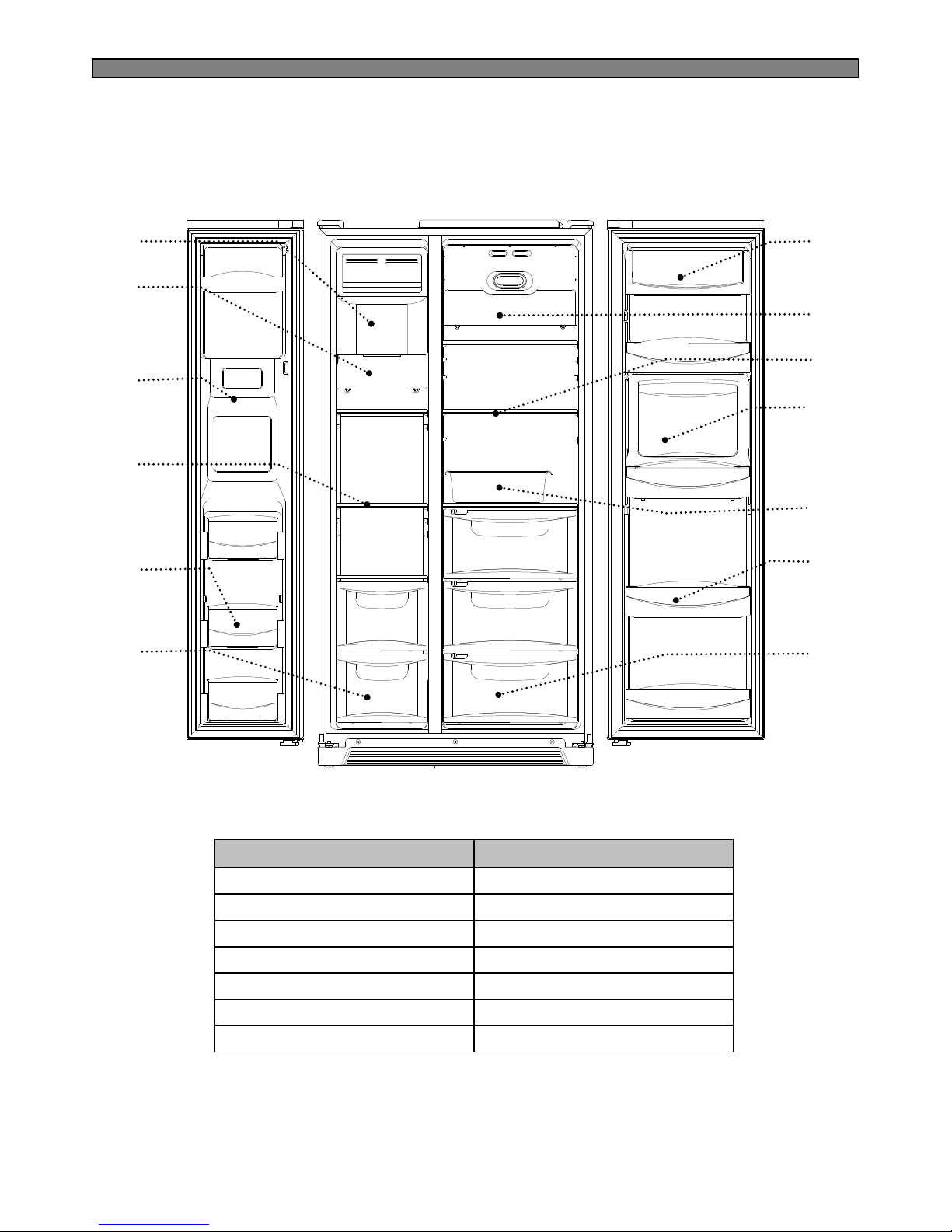
7. Dairy pocket1. Ice cubes storage case
12. Refrigerator case6. Freezer case
11. Refrigerator pocket5. Freezer pocket
10. Movable egg case4. Freezer shelf
9. Refrigerator shelf3. Water/Ice dispenser
8. Refrigerator light2. Freezer light
Refrigerator Compartment
Freezer Compartment
■ FRS(N)-U20DA
8
9
10
11
12
7
1
2
4
3
5
6
Page 9
8
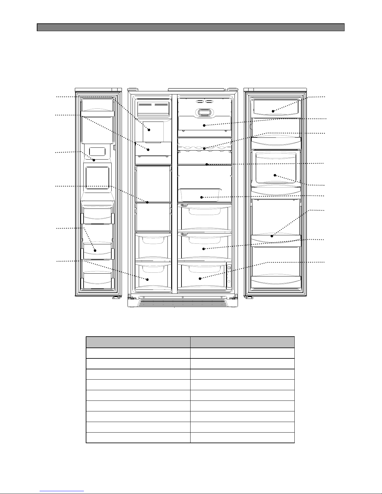
■ FRS(N)-U20EA
8
10
11
13
14
7
1
2
4
3
5
6
9
12
13. Refrigerator pocket
12. Refrigerator case6. Freezer case
7. Dairy pocket1. Ice cubes storage case
14. Magic cool zone
11. Movable egg case5. Freezer pocket
10. Refrigerator shelf4. Freezer shelf
9. Shelf wine (option)3. Water/Ice dispenser
8. Refrigerator light2. Freezer light
Refrigerator Compartment
Freezer Compartment
Page 10
9
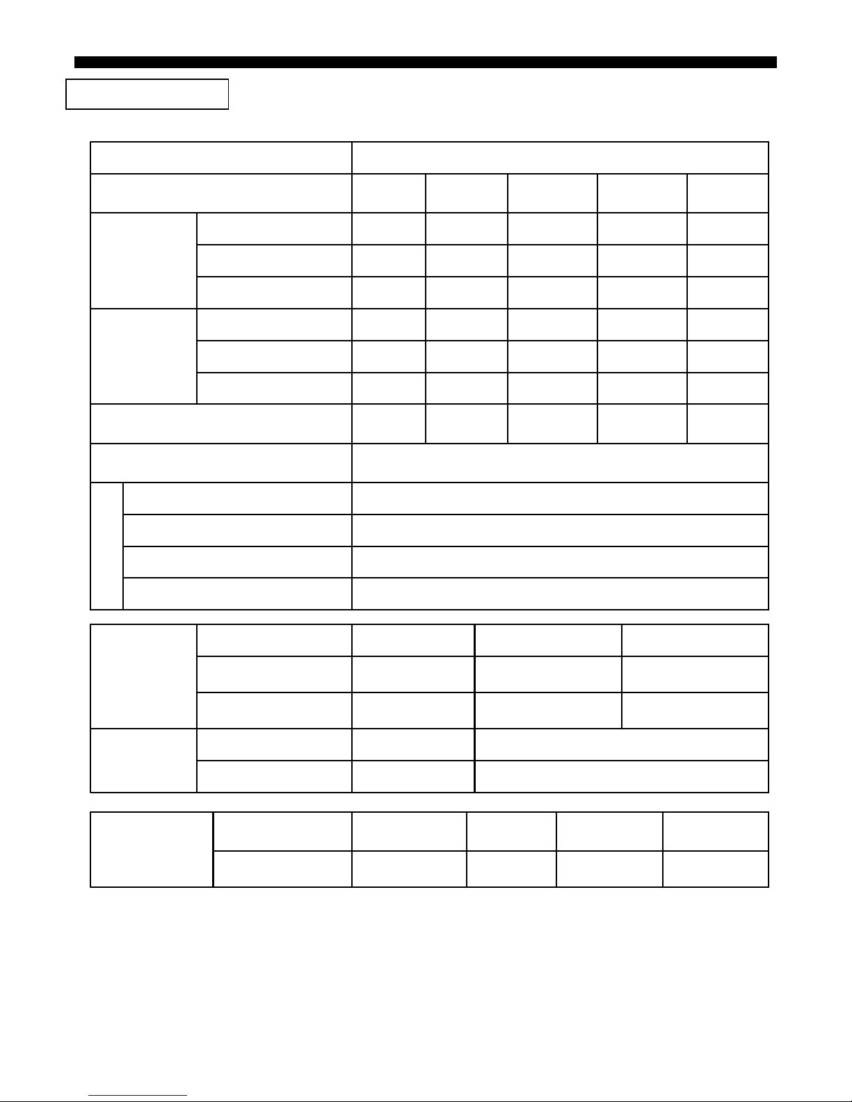
12. Refrigerator pocket6. Freezer case
7. Dairy pocket1. Ice cubes storage case
13. Refrigerator case
11. Movable egg case5. Freezer pocket
10. Homebar pocket4. Freezer shelf
9. Refrigerator shelf3. Water/Ice dispenser
8. Refrigerator light2. Freezer light
Refrigerator Compartment
Freezer Compartment
■ FRS(N)-U20FA
8
9
11
12
13
7
1
2
4
3
5
6
10
Page 11
10
■ FRS(N)-U20GA
8
9
11
12
15
7
1
2
4
3
5
6
10
13. Refrigerator pocket
14. Refrigerator case
12. Movable egg case6. Freezer case
7. Dairy pocket1. Ice cubes storage case
15. Magic cool zone
11. Homebar pocket5. Freezer pocket
10. Refrigerator shelf4. Freezer shelf
9. Shelf wine (option)3. Water/Ice dispenser
8. Refrigerator light2. Freezer light
Refrigerator Compartment
Freezer Compartment
13
14
Page 12
11
3. SPECIFICATION
3-1. Specification
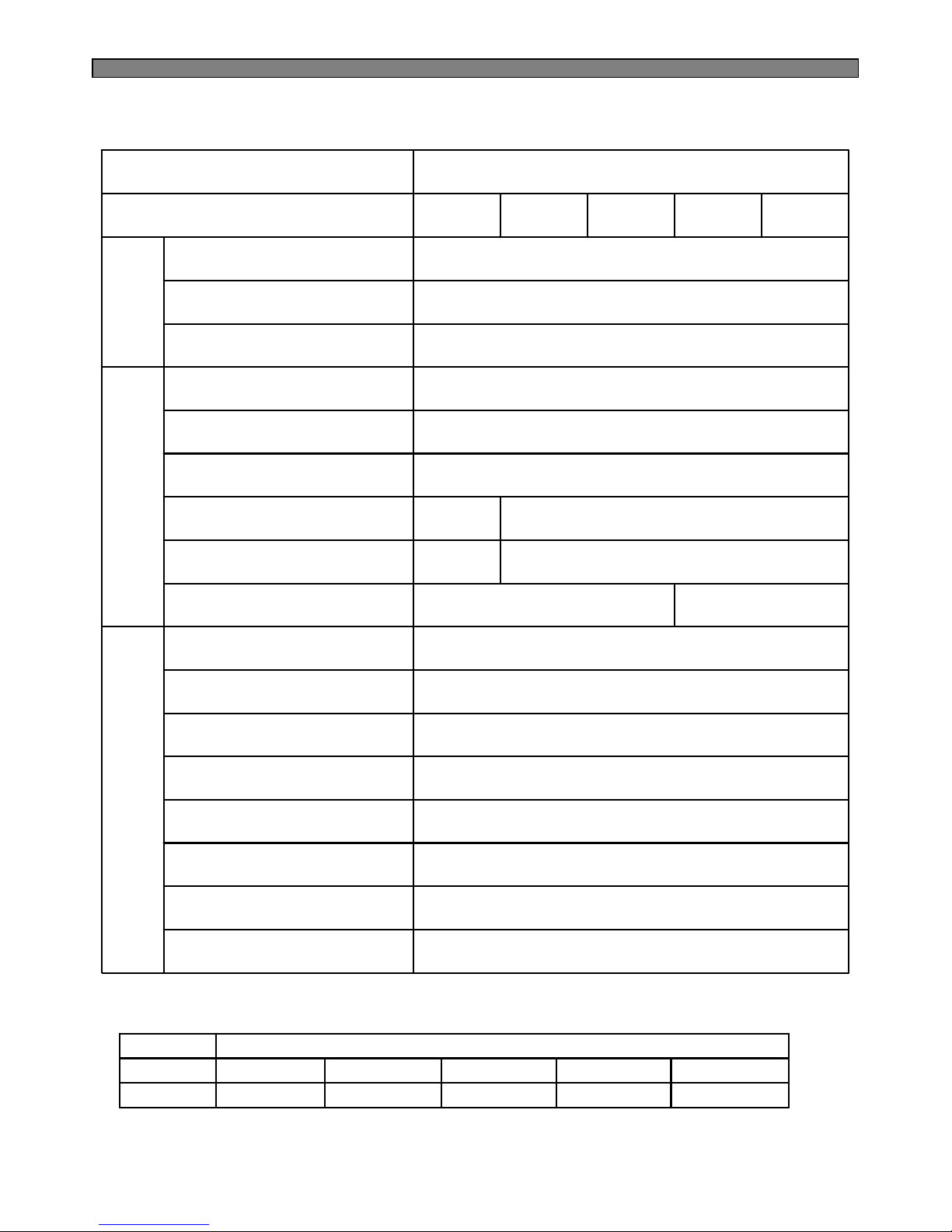
117kg115kg113kg 115kg
330 Li
170 Li
500 Li
352 Li
184 Li
536 Li
FRS(N)-
U20GA
334 Li
170 Li
504 Li
357 Li
184 Li
541Li
FRS(N)-
U20FA
334 Li
170 Li
504 Li
357 Li
184 Li
541 Li
FRS(N)-
U20DA
C
Y
C
L
E
IDΦ0.7 × T0.55 × L2200Capillary Tube
Molecular Sieve XH-9Dryer
Fan Cooling SystemCondenser
Fin TypeEvaporator
525 Li570 LiTotal
ISO Gross
Volume
(Li)
178 Li209 LiFreezer
337 Li361 LiRefrigerator
903 mm x 734.5mm x 1790 mm
104kg
339 Li
198 Li
537 Li
FRS(N)-
U20IA
External Dimension
(Width x Depth x Height)
Weight
334 LiRefrigerator
170 LiFreezer
504 LiTotal
ISO Storage
Volume
(Li)
FRS(N)-
U20EA
Model Name
SpecificationItem
R-600a (76g)R-134a (190g)R-134a (190g)Refrigerant ( g )
39561452503956183D50395S130R50Part Code
MK4A5Q-R1U
3011402100
265RHB, S330
MK183Q-L2UHPL30YG-5Description
Compressor
3018129810
308NHB, S330
Part Code
Description
SWITCH
P RELAY AS
3011347400
CP-2PIN
(Other Country)
301130108030113473003011346700Part Code
KP-550
(AUSTRALIA)
BS-1363
CP-2PIN
(EUROPE)
Description
CORD POWER AS
Page 13
12
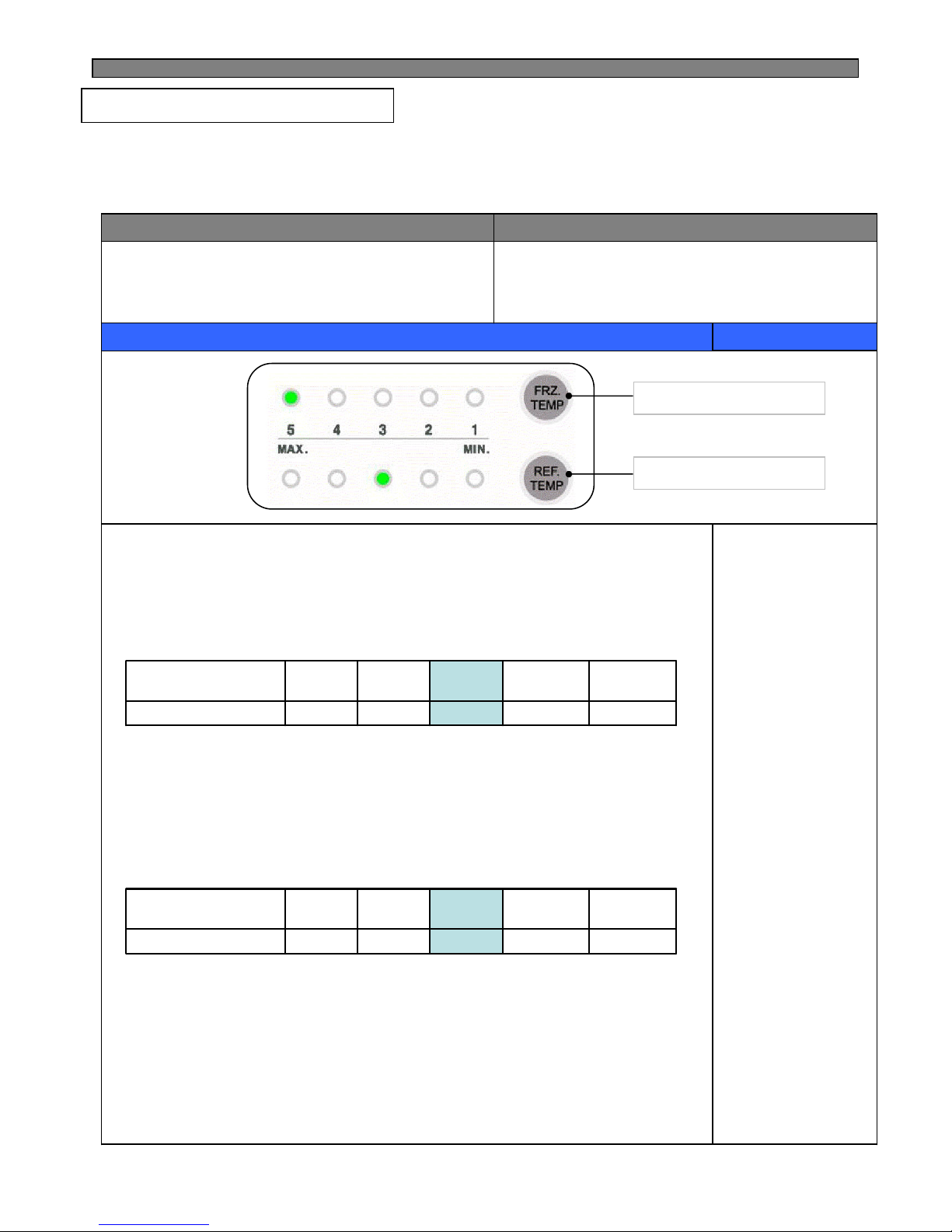
※ ( ) is the specification for the model which use R-600a(refrigerant)
AC220V / 10W
AC220V / 5W
-
Water Pipe Heater
SP201R-7DL / SP201R-7DR
(SPF101B-2D / SPF101B-1D)
Door Switch , F / R
AC230~240V / 25W (2EA)R-Lamp
AC230~240V / 25W (2EA)F-Lamp
DC13V / 1100±100 rpmCondenser Fan Motor
DC13V / 1850±100 rpm R-Fan Motor
DC13V / 2050±100 rpmF-Fan Motor
AC250V , 10A , 77
℃
Fuse Temp (Defrost)
AC250V 12AMain Fuse (Power cord)
P
A
R
T
S
E
L
E
C
T
R
I
C
A
L
-Homebar Heater
AC220V / 5W-Dispenser Heater
AC220V / 8WLouver Heater
AC220V / 7WMain Duct Heater
AC220V / 192WDefrost Heater
H
E
A
T
E
R
PBN-43R-Sensor
PBN-38F-Sensor
PBN-43D-SensorS
E
N
S
O
R
FRS(N)-
U20GA
FRS(N)-
U20FA
FRS(N)-
U20EA
FRS(N)-
U20DA
FRS(N)-
U20IA
Model Name
SpecificationItem
FRN-U20GAFRN-U20FAFRN-U20EAFRN-U20DAFRN-U20IAR-600a
FRS-U20GAFRS-U20FAFRS-U20EAFRS-U20DAFRS-U20IAR-134a
Model NameRefrigerant
Page 14
13
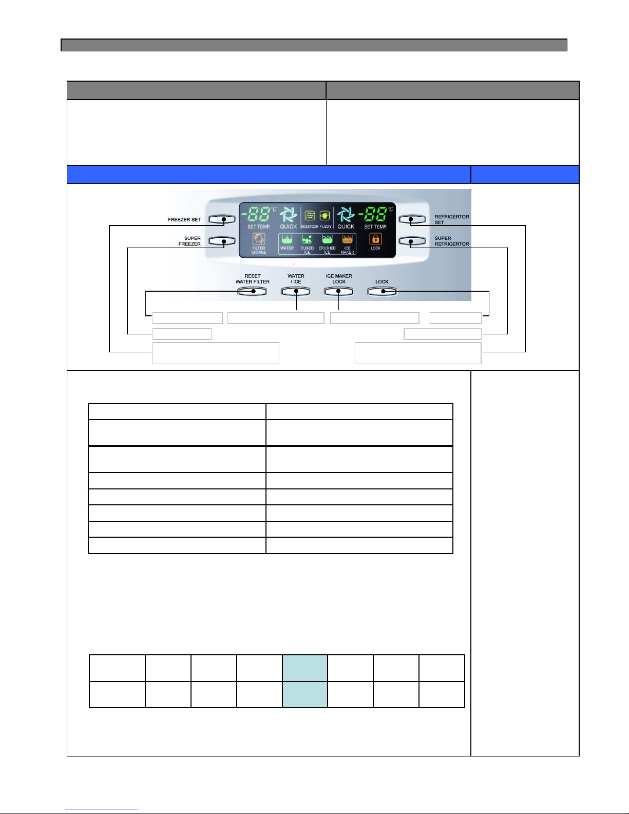
4-1. Display
54
321Temp indication
Max
Medium
Max
Mid
Medium
Min
MinTemperature Chang
54
321Temp indication
Max
Medium
Max
Mid
Medium
Min
MinTemperature Change
1. “FRZ.TEMP” Button
1) Temperature control of Freezer compartment
2) 5 step mode of successive temperature mode.
3) Initial mode by power input : “3”
※Whenever pressing button, setting is repeated in the order of
Medium(3) → Medium Max(4) → Max(5) → Min(1) → Medium Min(2).
2. “REF.TEMP” button.
1) Temperature control of Refrigerator compartment
2) 5 step mode of successive temperature mode.
3) Initial mode by power input : “3”
※Whenever pressing button, setting is repeated in the order of
Medium(3) → Medium Max(4) → Max(5) → Min(1) → Medium Min(2).
INPUT
CONTROL OBJECT
CONTENTS
REMARKS
FRZ.TEMP, REF.TEMP Inner Control (Lamp-LED)
4-1-1. FRS(N)-U20IA
※ The actual inner temperature varies depending on the food status, as the indicated setting
temperature is a target temperature, not actual temperature within refrigerator.
※ Refrigeration function is weak in the initial time.
Please adjust temperature as above after using refrigerator for minimum2~3 days.
Temperature adjustment button
for refrigerator compartment.
Temperature adjustment button
for freezer compartment.
4. OPERATION AND FUNCTIONS
Page 15
14
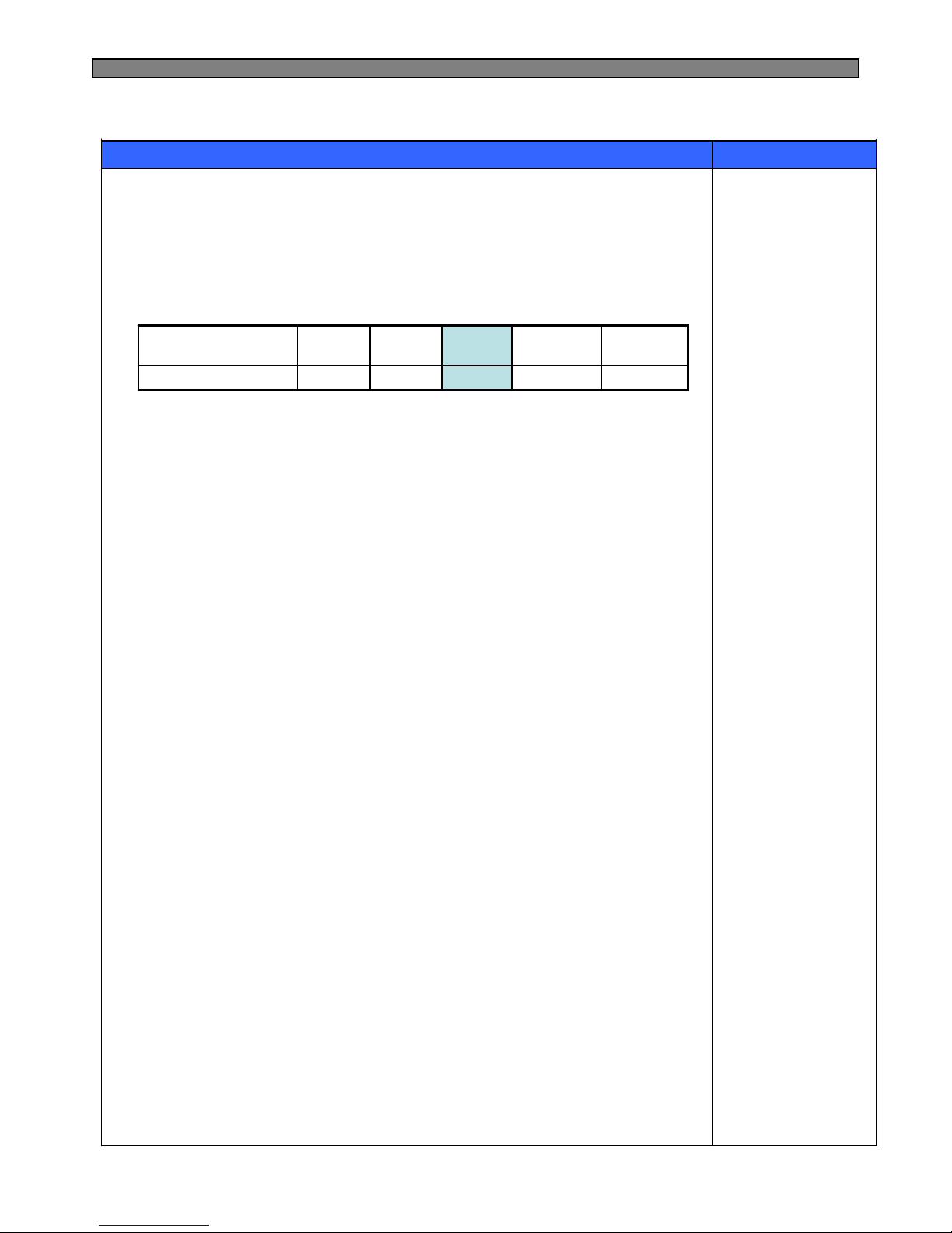
1. Display control
2. “FREEZER SET” Button
1) Temperature control of freezer compartment
2) 7 step mode of successive temperature mode.
3) Initial mode by power input : “Medium(-19℃)”
※Whenever pressing button, setting is repeated in the order of
Medium (-19℃) → Medium Max 1 (-20℃) → Medium Max 2 (-21℃) → Max (-22℃)
→ Min (-16℃) → Medium Min 2 (-17℃) → Medium Min 2 (-18℃).
INPUT
CONTROL OBJECT
CONTENTS
REMARKS
Front PCB button
FREEZER SET, REFRIGERATOR SET
SUPER FREEZER, SUPER REFRIGERATOR
RESET FILTER, WATER / ICE, ICE MAKER LOCK
,LOCK
FCP C-LED
3. “SUPER FREEZER” Button
When this mode is chosen, the icon (FREEZER QUICK) is ON.
After six month, LED ONFILTER CHANGE ICON
DialICE MAKER LOCK ICON
DialLOCK ICON
DialWATER / CUBED ICE/ CRUSHED ICE ICON
Always ONFUZZY, DEODORIZER ICON
Dial
SUPER FREEZER,SUPER
REFRIGERATOR ICON
Initial mode : Freezer & Refrigerator set→
Medium (-19℃/4℃)
88 DISPLAY (SET TEMP.)
ControlFCP-LED
-21℃
Medium
Max 2
-18℃
Medium
Min 2
-19℃
Medium
-22℃
Max
-20℃-17℃-16℃
Temp
indication
Medium
Max 1
Medium
Min 1
Min
Temperature
Change
4-1-2. FRS(N)-U20DA / EA / FA / GA
Temperature adjustment button
for freezer compartment.
Super freezer
Temperature adjustment button
for refrigerator compartment.
Super Refrigerator
Lock button
Water filter reset
Dispenser select button
Ice maker lock button
Letters are indicated on 88 Display LED
Page 16
15
CONTENTS
REMARKS
4. “REFRIGERATOR SET” button.
1) Temperature control of Refrigerator compartment
2) 5 step mode of successive temperature mode.
3) Initial mode by power input : “Medium (4℃)”
※Whenever pressing button, setting is repeated in the order of
Medium (4℃) → Medium Max (3℃) → Max (2℃) → Min (6℃) → Medium Min (5℃).
2℃3℃
4℃5℃6℃Temp indication
Max
Medium
Max
Mid
Medium
Min
MinTemperature Change
5. “SUPER REFRIGERATOR” button.
When this mode is chosen, the icon (REFRIGERATOR QUICK) is ON.
6. “WATER / ICE” button
1) Select Water / Cubed Ice / Crushed Ice.
2) Icon lights up to show your selection is on.
Initial mode by power input : “Water” mode.
3) The mode of Cubed Ice or Crushed Ice continues for 1 hour and then changes
to Water. (Water icon turns ON)
7. “ICE MAKER LOCK” button
1) Start by pushing “ICE MAKER LOCK” button
① “ICE MAKER LOCK” icon is on
② “WATER” icon is always on
2) Stop by pushing “ICE MAKER LOCK” button again
① “ICE MAKER LOCK” icon is off
② “WATER” icon is on
8. “RESET WATER FILTER” button
1) The normal (ICON OFF) is on for 6 month after are first power input.
2) After sic months, icon is ON.
3) How to reset Filter information
① Push the “RESET WATER FILTER” button for 3 seconds after change.
9. “LOCK” button
1) This button stops operation of different button.
① “LOCK” icon is on
② Press this button to lock out this case and to keep temperature and
function setting.
2) Push “LOCK” button again for more than a second to stop it.
※ The actual inner temperature varies depending on the food status, as the indicated setting
temperature is a target temperature, not actual temperature within refrigerator.
※ Refrigeration function is weak in the initial time.
Please adjust temperature as above after using refrigerator for minimum2~3 days.
Letters are indicated on 88 Display LED
REFERENCE : Please wait
for 2-3 seconds in order
to take final ice or drops
of water when taking out
cup from the pressing
switches after taking ice
or water.
Page 17
16
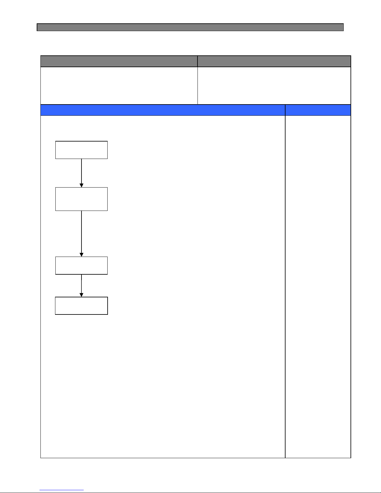
1. Defrost Mode
INPUT
CONTROL OBJECT
CONTENTS
REMARKS
1. Defrosting Cycle
1. Comp
2. F-Fan
3. R-Fan
4. D-Heater
Pre-Cool
Pause
Fan-Delay
Heater
Defrosting
Pre-Cool
1) Time : 50 minutes
2) Comp , F-fan : ON
R-fan : Control
D-HTR : OFF
3) If F-sensor ≤ -27℃, then Pre-Cool becomes. OFF
Heater
Defrosting
1) Comp, F-fan, R-fan : OFF
D-HTR : ON
2) Time limit
30 seconds : Heater is ON regardless of D-sensor
temperature right after defrosting start
30 minutes : in case of D1- Error
80 minutes : in normal control state
3) If D-sensor ≥13℃, Heater Defrosting is OFF
Pause
Time : 7 minutes
Comp, F-fan, R-fan, Heater etc. : OFF
Fan-Delay
1) Time : 5 minutes
Comp : ON and F-fan, R-fan, Heater : OFF
4-2. Defrost Mode
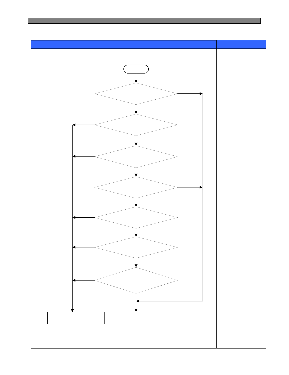
2.The defrost mode start with the following conditions
1) Total operation time of comp. becomes : 6,8,10,……… 24 hours.
① Comp. operating rate : more 85%
② Total door open time : 2 minutes
(Any door, F or R open time is over 2 minutes.)
③ Any error mode : R1, F1, D1, F3, RT/S, Door-switch etc.)
2) Defrosting mode starts unconditionally as long as total comp. work time is
24 hours, even if the above conditions 1) are not satisfied.
3) Defrosting mode starts immediately as long as total time of [comp. ON +
comp. OFF] is over 60 hours, even if the above 1) and 2) conditions are not
satisfied.
3. In providing initial power (or returning power failure)
If D-sensor temp. ≤ 3.5℃, defrosting mode starts .
Page 18
17
CONTENTS
REMARKS
4. Flow Chart of Defrosting Start
Start
Comp. operating time
is over 24 hours?
Total time is
over 60 hours?
Comp. operating time
is over 6 hours?
End
Defrosting start
Comp. operating time
is over 2 hours?
Any error ?
NO
YES
NO
NO
YES
Total door open
time is over 2 min?
YES
YES
YES
YES
NO
NO
NO
Comp. operating rate
is more 85%?
NO
YES
Page 19
18
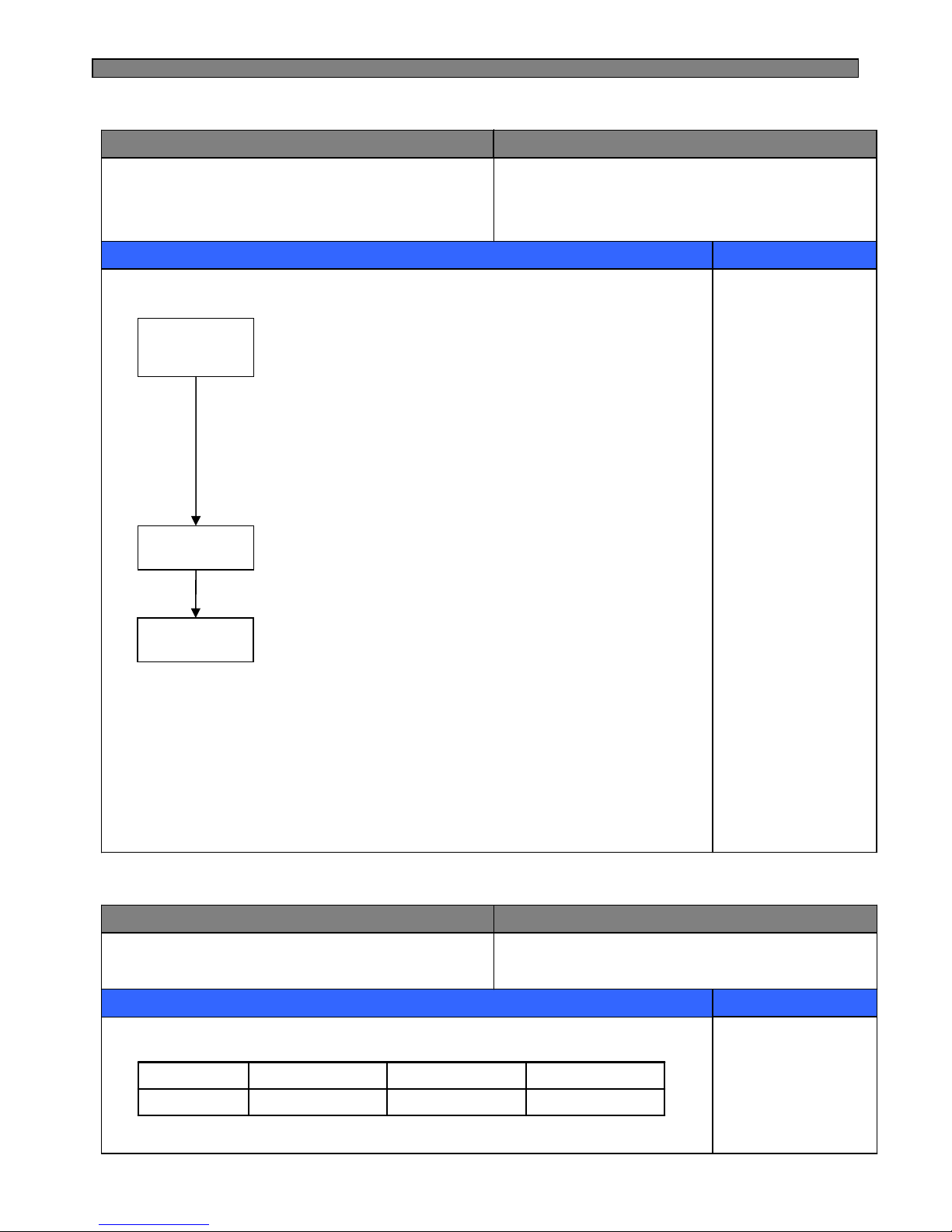
1. A/S Defrosting Mode (Heater defrost → Pause → Fan Delay)
INPUT
CONTROL OBJECT
CONTENTS
REMARKS
1. Defrosting Cycle
1. Comp
2. F-Fan
3. R-Fan
4. D-Heater
Heater
Defrosting
1) Comp, F-fan, R-fan : OFF
D-HTR : ON
2) Time limit
30 seconds : Heater is ON regardless of D-sensor
temperature right after defrosting start
30 minutes : in case of D1-Error
80 minutes : in normal control state
3) If D-sensor ≥13℃, Heater Defrosting is OFF
Pause
Time : 7 minutes
Comp, F-fan, R-fan, Heater etc. : OFF
Fan-Delay
1) Time : 5 minutes
Comp : ON
F-fan, R-fan, Heater : OFF
Pause
Fan-Delay
Heater
Defrosting
2. How to start
1) Push “REF.TEMP” button 5 times while pushing “FRZ.TEMP” button simultaneously.
--------- FRS-U20IA
2) In “LOCK” mode, push “REFRIGERATOR SET” button 5 times while pushing “FREEZER SET”
button simultaneously. ------ FRS(N)-U20DA
3. How to proceed
1) Delete Pre-cool mode. (Others are same as normal defrosting)
2) Heater is ON regardless of D-sensor temp. at first 30 seconds.
(Check of defrosting current)
4-3. c (Forced Defrosting) Mode
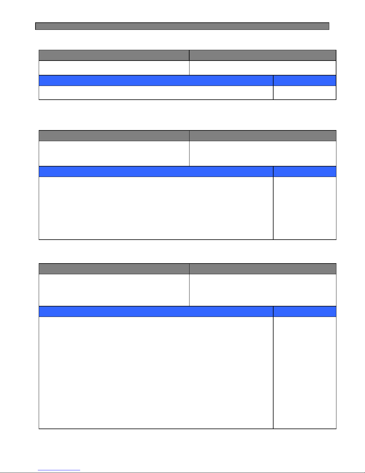
1. Fan voltage of control mode
INPUT
CONTROL OBJECT
CONTENTS
REMARKS
1. F-Sensor
2. R-Sensor
1. F-FAN, R-FAN, C-FAN
13 V13 V13 VVoltage
C-FANR-FANF-FANFAN
4-4. Fan Voltage of Control Mode
※ Refer to the 5-4. (Fan Function )
Page 20
19
It is linked with comp.
INPUT
CONTROL OBJECT
CONTENTS
REMARKS
1. Comp
Louver Heater
1. Buzzer sounds if any button of Inner Control is pushed.
2. Buzzer sounds 4 times 3 seconds after initial power input.
3. Buzzer sounds for 3 or 1 times in case of A/S forced defrosting and short (pull down)
operation or explanation mode.
4. If door is open, buzzer sounds after every 1 minutes for 5 minutes (Door open alarm)
INPUT
CONTROL OBJECT
CONTENTS
REMARKS
1. Control (Inner or F-PCB) buttons
2. Door Switch
3. Initial Power Input
Buzzer
4-5. Louver Heater Control
4-6. Buzzer or Alarm Control
1. Control refrigerator compartment lights
R-Lights turn ON/OFF by R-door switch ON/OFF
(※ For 10 minutes after sensing door open, the lights turn off automatically
through door close is not sensed.)
2. Control of freezer compartment lights.
F-Light turn ON/OFF by F-door switch ON/OFF
(※ For 10 minutes after sensing door open, the lights turn off automatically
through door close is not sensed.)
3. R-lights ON/OFF by home bar door switch ON/OFF. ( for only model with home bar )
R-lights turn ON for 10 minutes after sensing home bar door switch open.
4. Dispenser lamp control ( for only model with water/ice dispenser )
Dispenser lamp turns ON/OFF by Dispenser switch.
Dispenser lamp turns ON for 4 seconds after sensing switch close.
INPUT
CONTROL OBJECT
CONTENTS
REMARKS
1. Refrigerator door switch
2. Freezer door switch
3. Home bar door switch
4. Dispenser switch
Lamp
4-7. Control of Interior Lights (FRS(N)-U20DA / EA / FA / GA)
Page 21
20
1. Start
Open and close “Freezer door switch” 5 times while pushing “FRZ. TEMP” button
simultaneously.
2. Control
1) All other electrical components are OFF except for F-fan / R-fan
2) Fan Control
Door open → Fan ON / Door close → Fan OFF.
3) Display control
“FRZ. LED” and “REF. LED” are ON in good order
3. Stop
1) During Demo mode, push “Freezer door switch” open and close 5 times while pushing
“FRZ. TEMP” button simultaneously.
2) Power in again
INPUT
CONTROL OBJECT
CONTENTS
REMARKS
1. FRZ. TEMP
2. Door Switch
Comp
F/R-Fan
Heater
4-8. Demonstration
1. Start
Push “ICE/WATER” button 5 times while pushing “FREEZER SET” button
simultaneously.
2. Control
1) All other electrical components are OFF except for F-fan / R-fan
2) Fan Control
Door OPEN → Fan ON / Door close → Fan OFF.
3. Stop or termination
1) During Demo mode, push “ICE/WATER” button 5 times while pushing “FREEZER
SET” button simultaneously.
2) Power in again
INPUT
CONTROL OBJECT
CONTENTS
REMARKS
1. “FREEZER SET, WATER/ICE” Button , Door switch
Comp
F/R-Fan
Heater
4-8-1. FRS(N)-U20IA
4-8-2. FRS(N)-U20DA / EA / FA / GA
Page 22
21
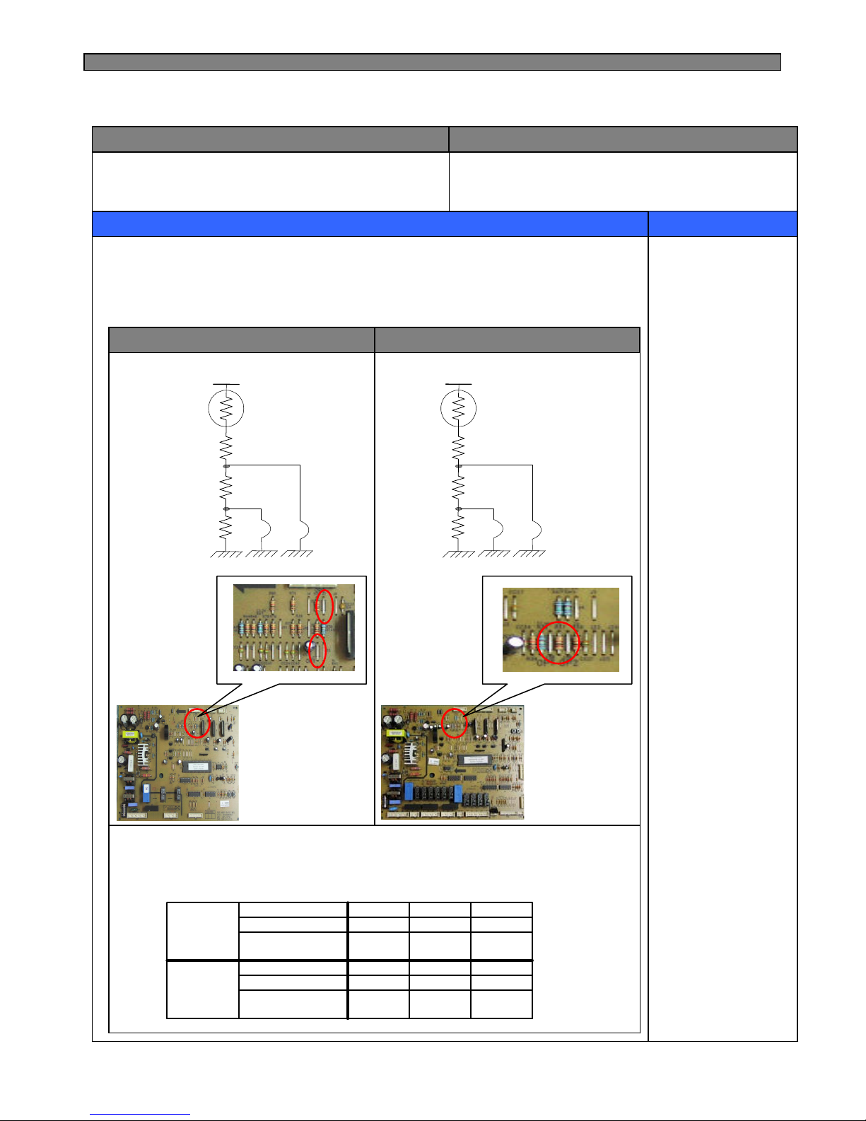
Compensation of R-sensor ON/OFF temp. (down)
In case temperature of refrigerator compartment is weak or insufficient,
take the following action.
INPUT
CONTROL OBJECT
CONTENTS
REMARKS
Main PCB
Resistance of R-sensor Mid ON/OFF Point
R36 : R-SENSOR standard resistance in normal mode (31.4K)
R37 : In case of weak ref., cut J1 (or J18) to down the standard resistance by 1.5deg(2K)
R38 : In case of weak ref., cut J2 (or J19) to down the standard resistance by 1.5deg(2K)
4-9. Compensation of R-sensor ON/OFF Point
FRS(N)-U20IA
FRS(N)-U20DA/EA/FA/GA
R-SENSOR
J2
R36
R37
R38
J1
R-SENSOR
J19
R36
R37
R38
J18
J1
J2
J18,19
※ Refer to the 5-2.
(Function of each sensor)
3
℃
-1.5
℃
0
℃
Temperature
compensation
cut--J19
cutcut-J18
FRS(N)
-U20DA
3
℃
-1.5
℃
0
℃
Temperature
compensation
cut--J2
cutcut-J1
FRS(N)
-U20IA
Page 23
22
1. How to start
1) Press “FRZ.TEMP” button 5 times while pressing
“REF.TEMP” button at the same time.
2. How to stop
1) Push “FRZ.TEMP” button 1 time.
2) It stops automatically in 4 minutes from the start.
3. All the error codes are reset if they turn to be normal.
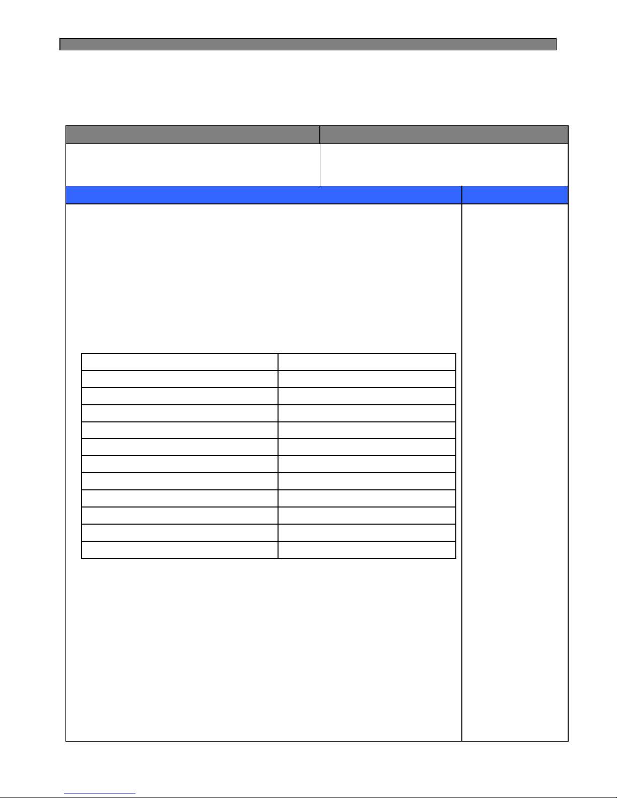
4. Error display
INPUT
CONTROL OBJECT
CONTENTS
REMARKS
Temperature Control Buttons Lamp LED of Inner control
(Full down mode and forced defrost mode are displayed while pressing
“REF.TEMP” button at the error display mode)
REF. LED “1” is on and off (twice)Forced defrost mode for A/S
REF. LED “1” is onFull Down mode
REF. LED “1” is on and offEEPROM : defective
REF. LED “2” is on and offReturn after defrosting : defective
REF. LED “3” is on and offCycle : defective
REF. LED “5” is on and offF-Door Switch : defective
FRZ. LED “1” is on and offR-Door Switch : defective
FRZ. LED “2” is on and offD-sensor : open (“Lo”), short (“Hi”)
FRZ. LED “3” is on and offRT-sensor : open (“Lo”), short (“Hi”)
FRZ. LED “4” is on and offR-sensor : open (“Lo”), short (“Hi”)
FRZ. LED “5” is on and off F-sensor : open (“Lo”), short (“Hi”)
DisplayCONTENTS
4-10. Error Display
4-10-1. FRS(N)-U20IA (LED Display of Inner Control)
Page 24
23
5. Control way of Errors (if any)
1) “F-sensor” error
Cause : F-sensor open or short
Control : Condition of ambient temperature
How to reset : If F-sensor is normal, the error is terminal temperature.
CONTENTS
REMARKS
2) “R-sensor” error
Cause : R-sensor open or short
Control : Condition of ambient temperature
How to reset : If R-sensor is normal, the error is terminal temperature.
3) “RT-sensor” error
Cause : RT-sensor open or short (full down)
Control : Normal operation, deletion of control by RT-sensor
If RT-sensor is normal, the error is terminated automatically.
4) “D-sensor” error
Cause : D-sensor open or short (full down)
Control : Time limit (30 min) of defrosting return
If D-sensor is normal, the error is terminated automatically.
5) “Door” error
Cause : in case it senses that door is open for more than 1 hour.
Control : Deletion of function related door switch sensing
If door switch (open & close) is sensed, the error is terminated automatically.
6) “Cycle” error
Cause : in case comp. works for over 3 hours when D-sensor temp. is over -5℃
Control : normal operation
When D-sensor temp. is below -5℃ in comp. off it is terminated.
7) “Return after defrosting” error
Cause : in case defrosting return is done by time limit of 80 min
Control : Deletion of Pre-cool mode in defrosting mode
If defrosting return is done by D-sensor, it is terminated.
8) A/S forced defrosting mode
Push “REFRIGERATOR SET” button 5 times while pushing “FREEZER SET” button
Simultaneously.
Control : A/S forced defrosting control (Pre-cool is deleted)
If D-sensor temp. is over 10℃, the mode is terminated automatically.
When all error code is normal, the Refrigerator reset
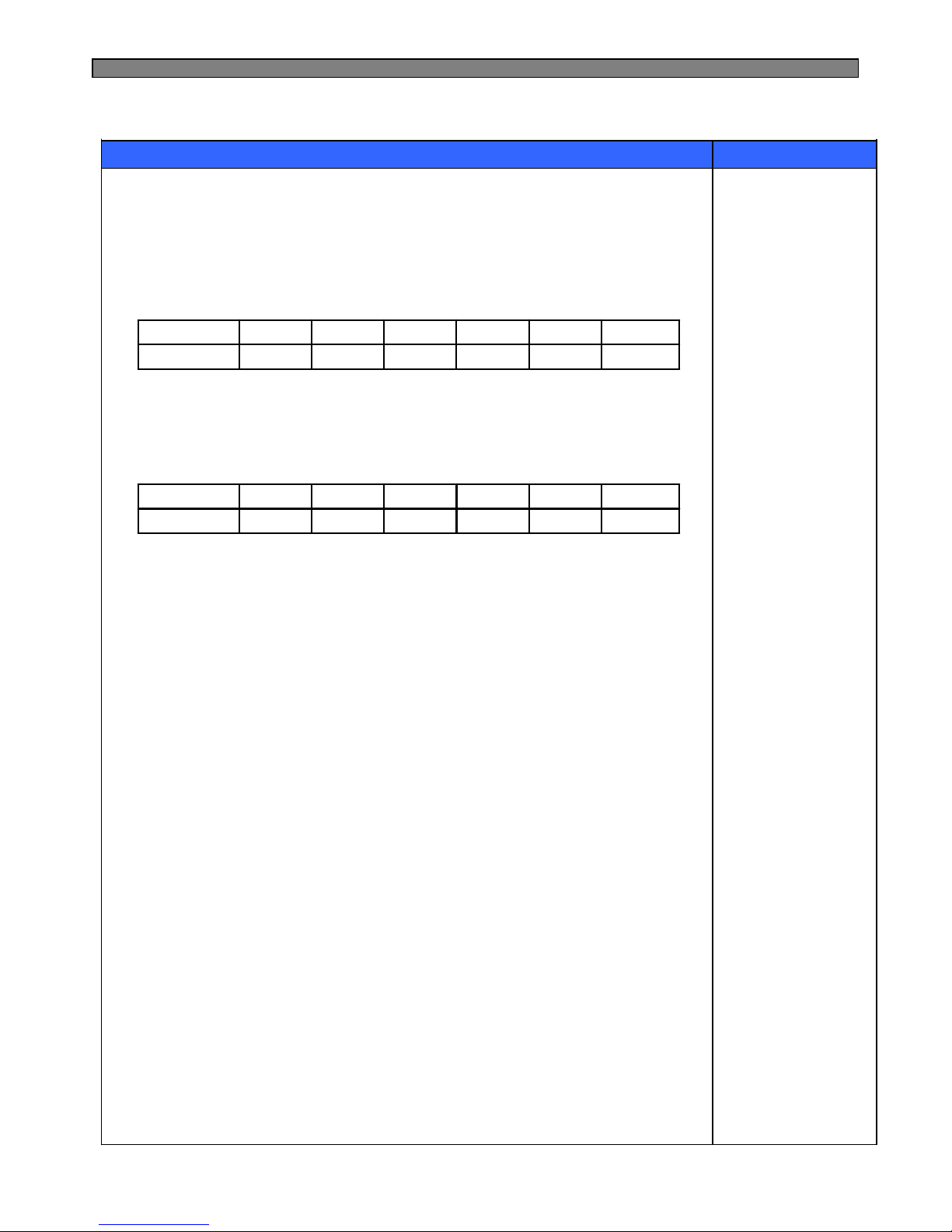
35 / 2035 / 2026 / 2227 / 4516 / 4114 / 50ON/OFF (min)
Over 41℃~ 41℃~ 31℃~ 21℃~ 15℃~ 9℃RT-S
6 / 44 / 63 / 72 / 103 / 50OFFON/OFF (min)
Over 41℃~ 41℃~ 31℃~ 21℃~ 15℃~ 9℃RT-S
Page 25
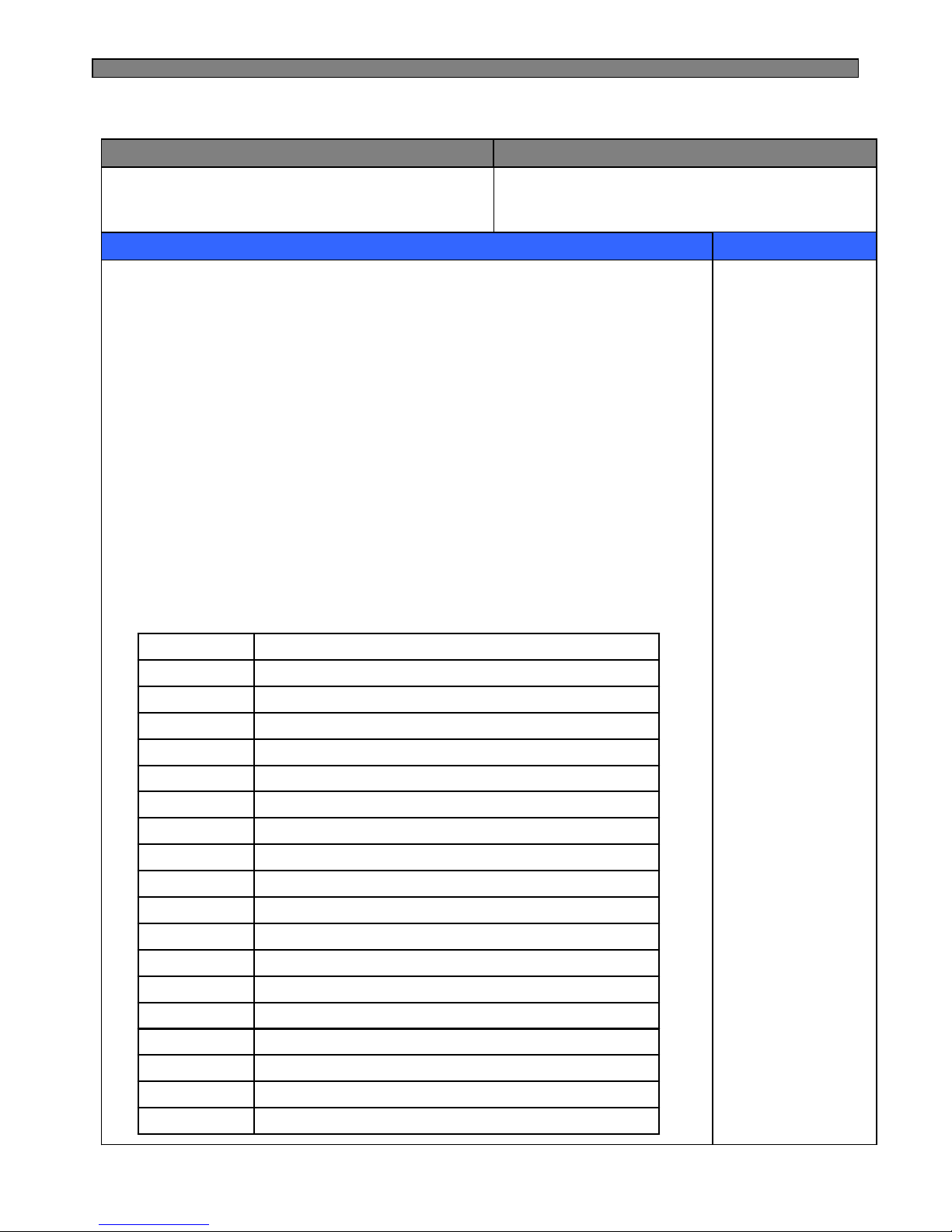
24
1. How to start
1) Under “LOCK” mode, press “SUPER FREEZER” button 5 times while pressing
“FREEZER SET” button at the same time.
2) The front CLED displays as the right diagram shows
( [Ex.] Time Display of 0003 signifies 3 minutes of power on time.)
3) Press “FREEZER SET” button and the following value is displayed successively.
① Time
② F-Sensor temperature
③ D-Sensor temperature
④ R-Sensor temperature
⑤ RT-Sensor temperature
⑥ P Factor display (Refer to water supply mode of automatic icemaker)
⑦ Filter remaining time until change (First check ; 4,320Hr)
Refer to Filter Information Reset of CLED of front control panel.
4) Error is displayed only if there is any ; it is skipped if no error.
2. How to stop
1) Push “LOCK” button 1 time.
2) It stops automatically in 4 minutes from the start.
3. All the error Codes are reset if they turn to be normal.
4. Error code
INPUT
CONTROL OBJECT
CONTENTS
REMARKS
Temperature Control Buttons 88 Display CLED
Display forced defrost mode for A/SD2
Display Full Down modeCo
Return after defrosting : abnormal or defectiveF3
Cycle : abnormal or defectiveC1
Full ice switch : errorEu
Drop the ice while EtEA
Micro switch : errorES
Water supply : errorEg
Horizontal switch : errorEt
Flow sensor : defectiveEF
I-sensor : disconnection (“Lo”), short (“Hi”)EI
Home bar Door Switch : defectivedH
F-Door Switch : defectivedF
R-Door Switch : defectivedr
D-sensor : disconnection (“Lo”), short (“Hi”)d1
RT-sensor : disconnection (“Lo”), short (“Hi”)rt
R-sensor : disconnection (“Lo”), short (“Hi”)r1
F-sensor : disconnection (“Lo”), short (“Hi”)F1
CONTENTSERROR CODE
4-10-2. FRS(N)-U20DA/EA/FA/GA (CLED Display of Front PCB)
Page 26
25
1) “F1” error
Cause : F-sensor disconnection or short
Check point : Measure the resistance between both terminals after separating CN8 (or CN15)
of the Main PCB. (Refer to the 5-2.)
If F-sensor is disconnected or shorted , change the F-sensor in the freezer compartment.
How to reset : If F-sensor is normal, the error is terminal temperature.
CONTENTS
REMARKS
2) “R1” error
Cause : R-sensor disconnection or short
Check point : Measure the resistance between both terminals after separating CN7 (or CN14)
of the Main PCB. (Refer to the 5-2.)
If R-sensor is disconnected or shorted , change the F-sensor in the refrigerator compartment.
How to reset : If R-sensor is normal, the error is terminal temperature.
7) “F3” error
Cause : in case defrosting return is done by time limit of 80 min
Check point : Measure the resistance between both terminals of the defrost heater.
(Assembled with evaporator)
If the resistance is ∞Ω (disconnected) or 0Ω (short) change the
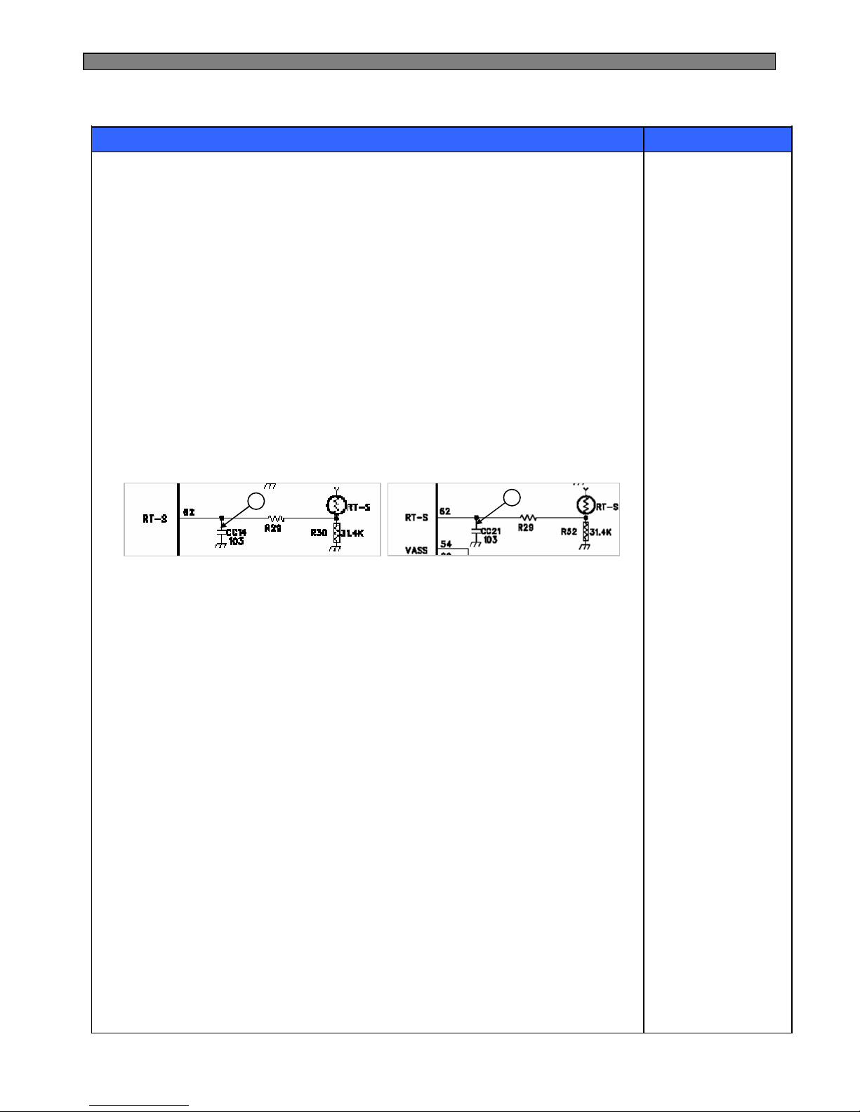
3) “rt” error
Cause : RT-sensor disconnection or short (full down)
Check point : Measure the voltage of “A” part on the Main PCB.
If the voltage is 0.5V~4.5V, it is normal.
If the voltage is 0V (short) or 5V (disconnected), change the RT-sensor on the Main PCB
How to reset : If RT-sensor is normal, the error is terminated automatically.
< FRS(N)-U20IA >
A
< FRS(N)-U20DA >
A
4) “d1” error
Cause : D-sensor disconnection or short (full down)
Check point : Measure the resistance between both terminals after separating CN8 (or CN15)
of the Main PCB. (Refer to the 5-2.)
If D-sensor is disconnected or shorted , change the D-sensor on the evaporator.
How to reset : If D-sensor is normal, the error is terminated automatically.
5) Door error (“dF” “dR” “dH” on display)
Cause : in case it senses that door is open for more than 1 hour.
Check point : F/R door is opened or not.
6) “C1” error
Cause : in case comp. works for over 3 hours when D-sensor temp. is over -5℃
Check point : Refrigerant leakage.
8) “d2” mode (A/S forced defrosting mode)
Push “REFRIGERATOR SET” button 5 times while pushing “FREEZER SET” button
simultaneously.
Control : A/S forced defrosting control (Pre-cool is deleted)
If D-sensor temp. is over 10℃, the mode is terminated automatically.
Refer to the 4-3. .
5. Control way of Error (if any)
Page 27
26
9) “EI”ERROR
Cause : I-SENSOR disconnection / short
Check point : Measure the resistance between both terminals after separating CN11
of the Main PCB. (Refer to the 5-2.)
If F-sensor is disconnected or shorted , change the I-sensor in the automatic ice maker.
CONTENTS
REMARKS
10) “EF” ERROR
Cause : When Flow-sensor ERROR (There is no Pulse during some time)
The number of pulse signal is below 10 by 1 sec during water supply.
Check point : Water supply line
13) “Ea” error
Cause : Malfunction of ice drop motor.
Check the motor by pushing test switch.
11) “Eg” ERROR
Cause : I-sensor temp (5min after water supply) doesn’t go up.
Check the I-sensor or water supply line.
12) “ES” error (MICRO switch error)
Cause : When it senses 1min continuously
Check the MICRO switch of the dispenser.
14) “Eu” error
Cause : Switch (which senses if the ice is full or not) is in error.
Control : When dropping the ice, the motor just rotates 90 degree.
Termination : When the switch is in normal.
15)“EA“ ERROR
Cause : When sensing Ice dropping by time 3 times in level sensor SW Error.
Control : Stop of Ice Maker
Termination : With normal level switch.
Re-input of power or push if icemaker test switch.
16)“Et” ERROR
Cause : Level switch error (No pulse is sensed for some time)
Control : By time (Supply mode is skipped)
Termination : Normal condition.
* When all ERROR CODE is normal, the Refrigerator reset
Page 28
27
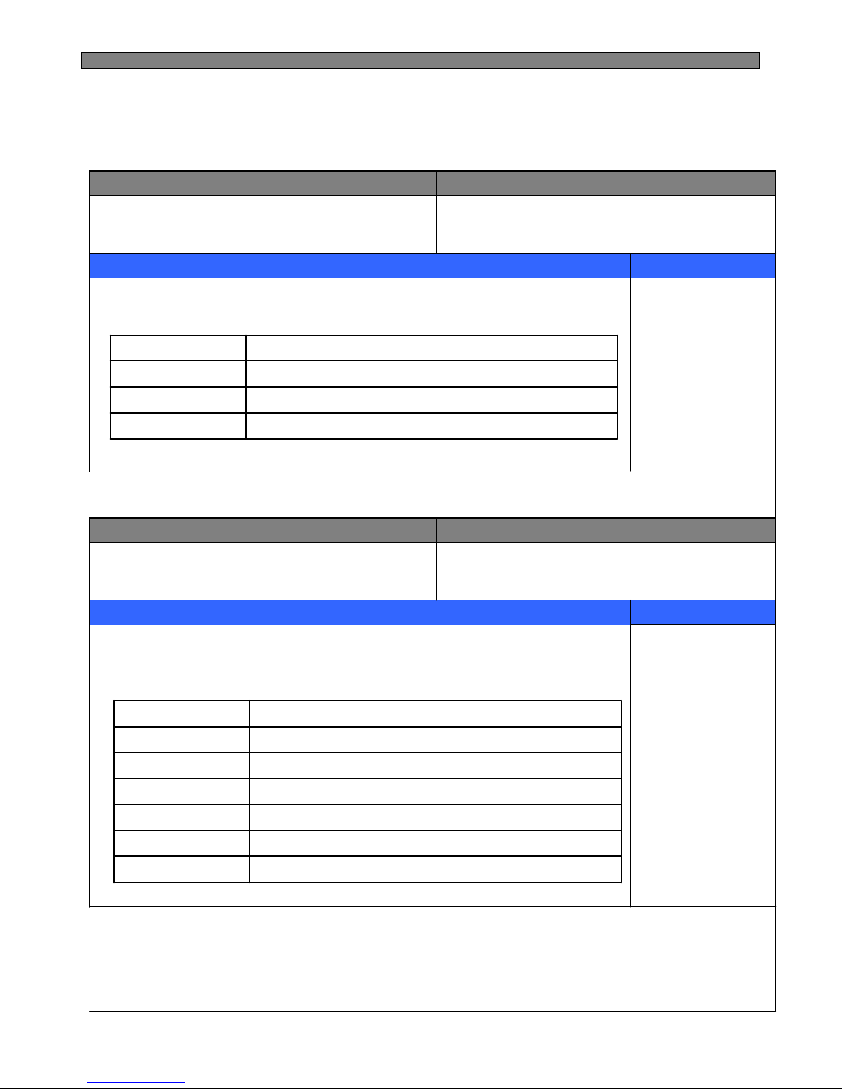
Element A/S Function
INPUT
CONTROL OBJECT
CONTENTS
REMARKS
Each button
Resistance of R-sensor Mid ON/OFF Point
“REF.TEMP”+ “FRZ.TEMP” 5 timesError display
“FRZ.TEMP”+ “FRZ.DOOR” OPEN/CLOSE 5 timesDemo function
“REF.TEMP”+ “FRZ.DOOR” OPEN/CLOSE 5 timesPull Down
“FRZ.TEMP” + “REF.TEMP” 5 timesForced Defrosting
1. All the modes are started “LOCK” mode (except “FILTER RESET” mode)
2. Element A/S Function
INPUT
CONTROL OBJECT
CONTENTS
REMARKS
Each button
Resistance of R-sensor Mid ON/OFF Point
“WATER/ICE” + “ICE MAKER LOCK” 5 timesIce maker test
“WATER/ICE”+ “RESET WATER FILTER” 5timesEEPROM clear
“FREEZER SET”+ “SUPER FREEZER” 5 timesError display
“REFRIGERATOR SET”+ “FREEZER SET”+ “WATER/ICE”5 timesPull Down
“REFRIGERATOR SET” + “WATER/ICE” 5 timesDemo function
Push “RESET WATER FILTER” for 3 secondsReset water filter
“FREEZER SET” + “REFRIGERATOR SET” 5 timesForced Defrosting
4-11. Summary of Function
4-11-1. FRS(N)-U20IA (Inner Control)
4-11-2. FRS(N)-U20DA/EA/FA/GA (Front PCB)
Page 29
28
1. Filter Exchange Information : Record as a real-time from the point of
power input
2. P Factor (Information about Ice Maker)
INPUT
CONTROL OBJECT
CONTENTS
REMARKS
None
1. F-FAN, R-FAN, C-FAN
INPUT
CONTROL OBJECT
CONTENTS
REMARKS
Full ice sensing switch
Ice Maker Lock
Sensors
Ice separating motor
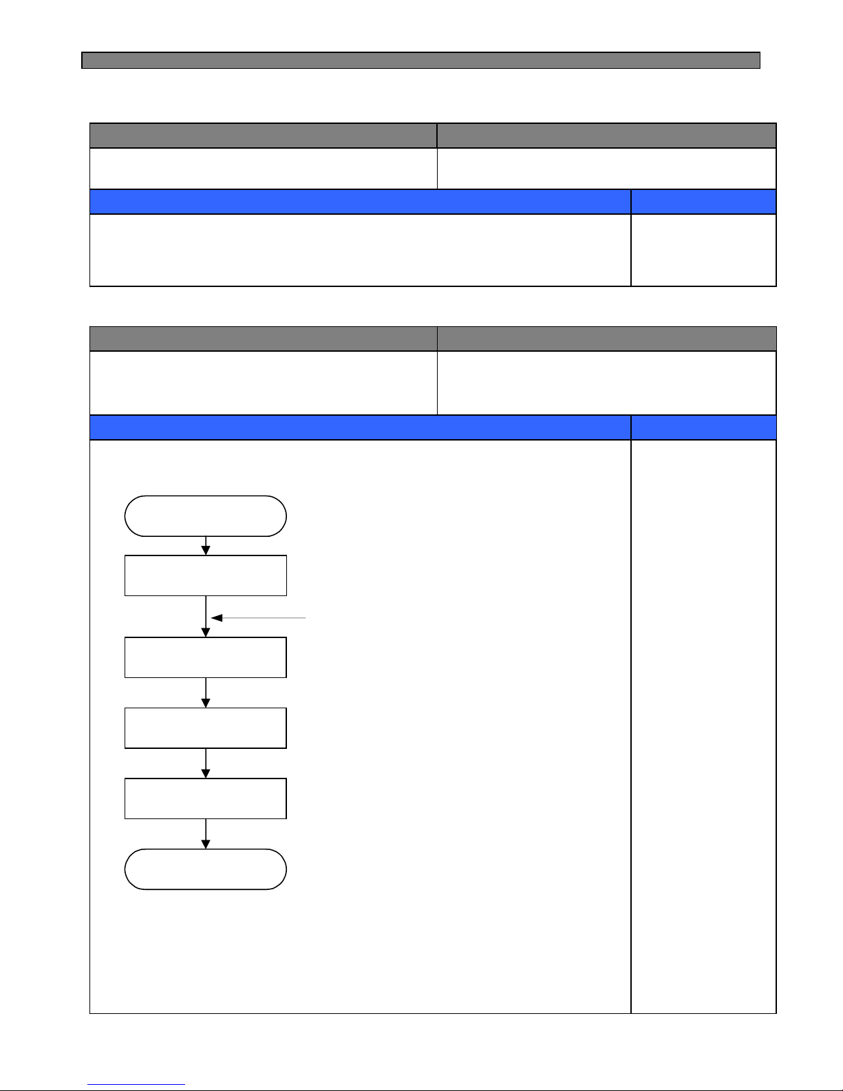
1. Flow of ice making
1) Press TEST switch under the Icemaker for more than 1 second and test starts.
* Test mode starts from ice separating mode.
* In case test switch has an error of short, test is done only once.
START
Ice making mode
Ice separating mode
Water supply mode
Water supply
check mode
RETURN
Ice is being made
▶
▶
Ice tray is twisted to separate
ice cubes
▶
Water is supplied to ice tray
▶
Check is water is supplied OK.
(water supply stand by)
4-12. Back up Function (FRS(N)-U20DA/EA/FA/GA)
4-13. Automatic Icemaker ( FRS(N)-U20DA/EA/FA/GA)
Page 30
29
CONTENTS
REMARKS
2) With the initial power input, Ice tray turns to be horizontal and ice making
mode starts.
3) Control of water hose heater
* Heater is always ON if RT-sensor has an error or RT is below 15 degree.
* Heater is always ON for 60 minutes (max. Limit time) if Flow-sensor has
an error
4) Water supply stand-by
Condition : if ice is sensed full
Operation : proceeds to Ice making mode (Ice separating and water supply Modes stop)
5) Crusher Function
It stops operation when freezer door is open
It operates if freezer door is closed.
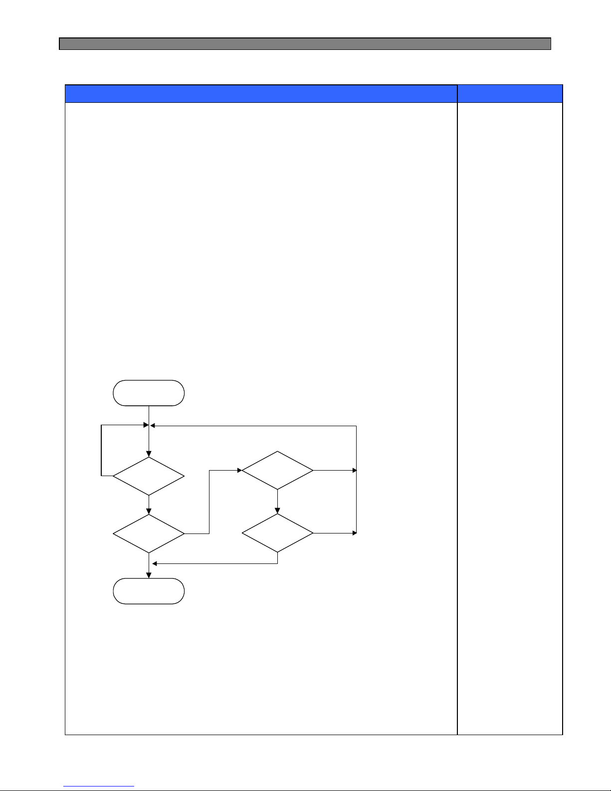
2 Ice making mode
START
130 min passed?
I-S<-12.5℃
Ice saparating mode
I-S<-9.5℃
15 min passed?
NO
NO
YES
YES
YES
NO
NO
YES
1) Ice making stops if ice-sensor is below -12.5℃ after 130 minutes.
2) Ice making also stops if ice-sensor is below -9.5℃ for 15 minutes, though
ice-sensor is not below -12.5℃ after 130 minutes.
3) In case of ice sensor, ice making stops after 4.8 hours.
Page 31
30
CONTENTS
REMARKS
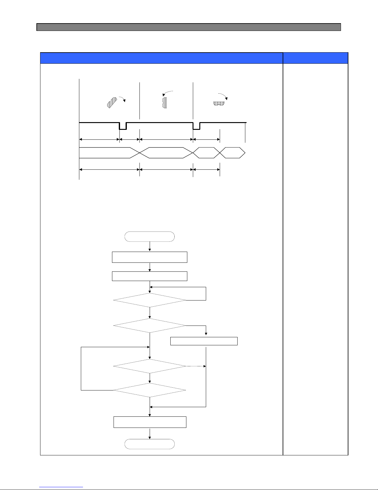
3. Ice separating (drop) mode
CCW
CW
STOP
CW
motor
revolution
level SW
status of
ice tray
Horizontal position
Ice separation start
8~11sec
MAX1.1sec 8.5~12.2sec 0.2sec
normal
level SW
level SW
error
1.1 sec11 sec10 sec
1) Time of each zone used to verify level switch error
2) The rotation of motor is sensed at each zone
3) In case of level switch error, ice separation is done by time.
4) If ice separating motor has error, the mode stop.
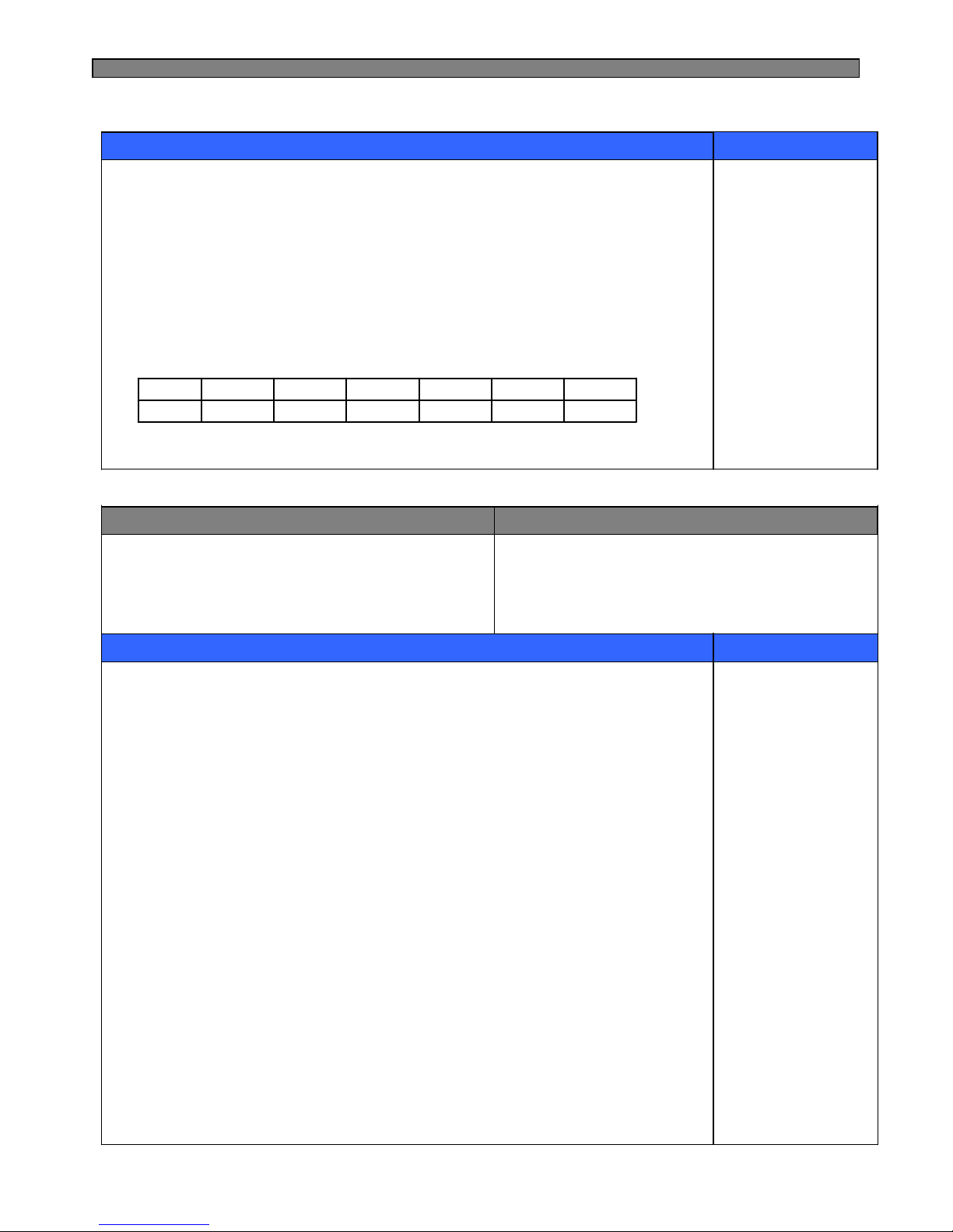
4. Water supply mode
START
Water supply valve ON
Water flow Pulse Count = 0
N
Water flow Pulse spec
〉Pulse spec
END
water supply time 〉time spec
water supply valve OFF
Y
1sec passed after
water valve ON ?
Water flow Pulse > 10
Flow-Sensor Error mode operation
Y
N
Y
Y
N
N
Page 32
31
CONTENTS
REMARKS
1) Water supply valve is open when water supply mode starts after separation of ices.
2) Water is supplied by time in case sensor has error.
3) Factor valve is variable which can be useful in AS action
① Water flow pulse is set to 238 if flow sensor is in normal condition.
(If water is supplied by time, maximum water supply time 165 seconds)
② In case water flow sensor has error, water time is 5.5 seconds.
5. Water supply check mode
5 minutes after water supply the status can be checked by RT-sensor and increase
of temp. Ice sensor.
-5℃-6℃-7℃-8℃-9℃-10℃I-S
41℃↑~41℃~31℃~21℃~15℃9℃↓RT-S
4-14. Dispenser Control Function
INPUT
CONTROL OBJECT
CONTENTS
REMARKS
Dispenser switch
WATER/ICE Button
ICE MAKER LOCK Button
Freezer Door Switch
Dispenser Lamp
Crusher Motor
Flap Solenoid
Crusher Solenoid
Dispenser Water Valve
1) Initial mode : water
(Mode change : Water → Cubed ice → Crushed ice)
- Selected icon LED turns ON and others are OFF.
2) ICE MAKER LOCK Button
Icemaker Lock function and its ICON Turn ON/OFF by pressing the button.
3) Display
① Water ICON turns ON as default mode
② The ICON of each mode turns ON by pressing its button.
(If display switch makes error during operation of a mode, its ICON turns OFF)
③ When Icemaker Lock ICON turns ON.
- ICE MAKER LOCK ICON turns ON
- If it is in the mode of Cubed Ice or Crushed Ice, the mode is changed to
Water and Water ICON turns ON
- If there is no button input for 1 hour after selecting Cubed Ice or Crushed
Ice the mode turns to Water (default)
Page 33
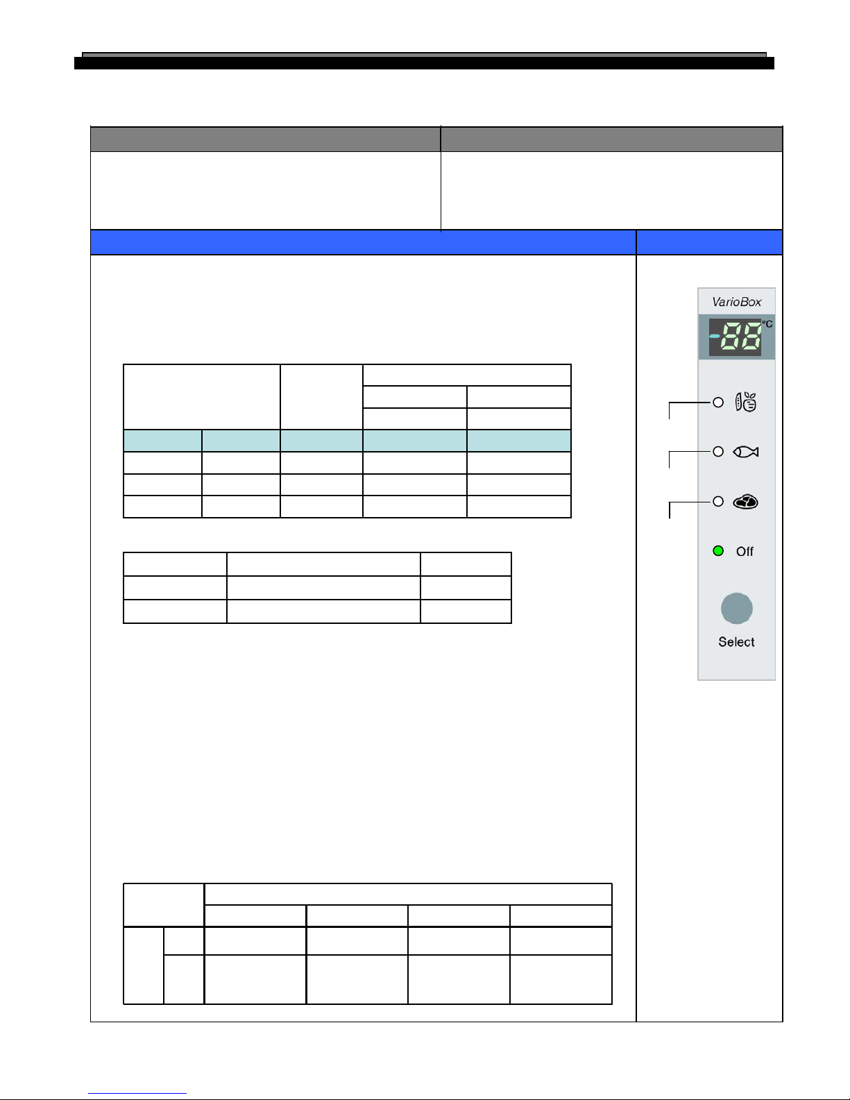
32
1. “Select” button
1) Temperature control of “Magic Cool Zone” compartment
2) 4 step mode of successive temperature mode.
Initial mode by power input : “OFF”
(“Off” → “Vegetable” → “Fish”→ “Meat”→ “Off”)
Letters are indicated on “88” display LED
INPUT
CONTROL OBJECT
CONTENTS
REMARKS
1. R-Fan
2. “Magic Cool Zone” sensor
3. “SELECT” button
1. “Magic Cool Zone” damper
2. Damper heater
4-15. Temperature control of “Magic Cool Zone” compartment (
FRS(N)-U20EA/GA)
2. Normal Stepping motor Control (It is linked with Refrigerator Fan (R-Fan))
3. Damper heater control
1) Damper open → Damper heater OFF
2) Damper close → Damper heater ON
4. How to check error mode (Temp. display and forced damper Open/Close)
1) How to start
Push “Select” button for 2 seconds.
① Initial display : “sensor temp.” display. (if sensor is normal)
“Er” display. (if sensor is disconnected or short)
② Press “Select” button 1 time : “OP” display. (forced damper open )
③ Press “Select” button 2 time : “CL” display. (forced damper close )
2) How to stop
It stops automatically in 20 sec. from the start.
5. Control way for “Magic Cool Zone” sensor error.
1) If “Magic Cool Zone” sensor is disconnected or short.
2) Damper open and close by below table. Control (Condition of “Select” button)
-
-
-
Off
Power input
3’rd Press
2’nd Press
1’st Press
01-3Meat
23-1Fish
893Vegetable
Temp (℃)Temp (℃)
CloseOpen
Damper Open/Close point
DisplayMode
Each mode ON/OFF ControlOFF
Always closeON
Remark“Magic Cool Zone” damperR-Fan
R-Fan
“Select”
Close
Close
“Off”
Open
After 2min open
from R-Fan off,
and then close
CloseOFF
CloseCloseCloseON
“Meat”“Fish”“Vegetable”
Condition
“Vegetable”
“Fish”
“Meat”
Page 34
33
CONTENTS
REMARKS
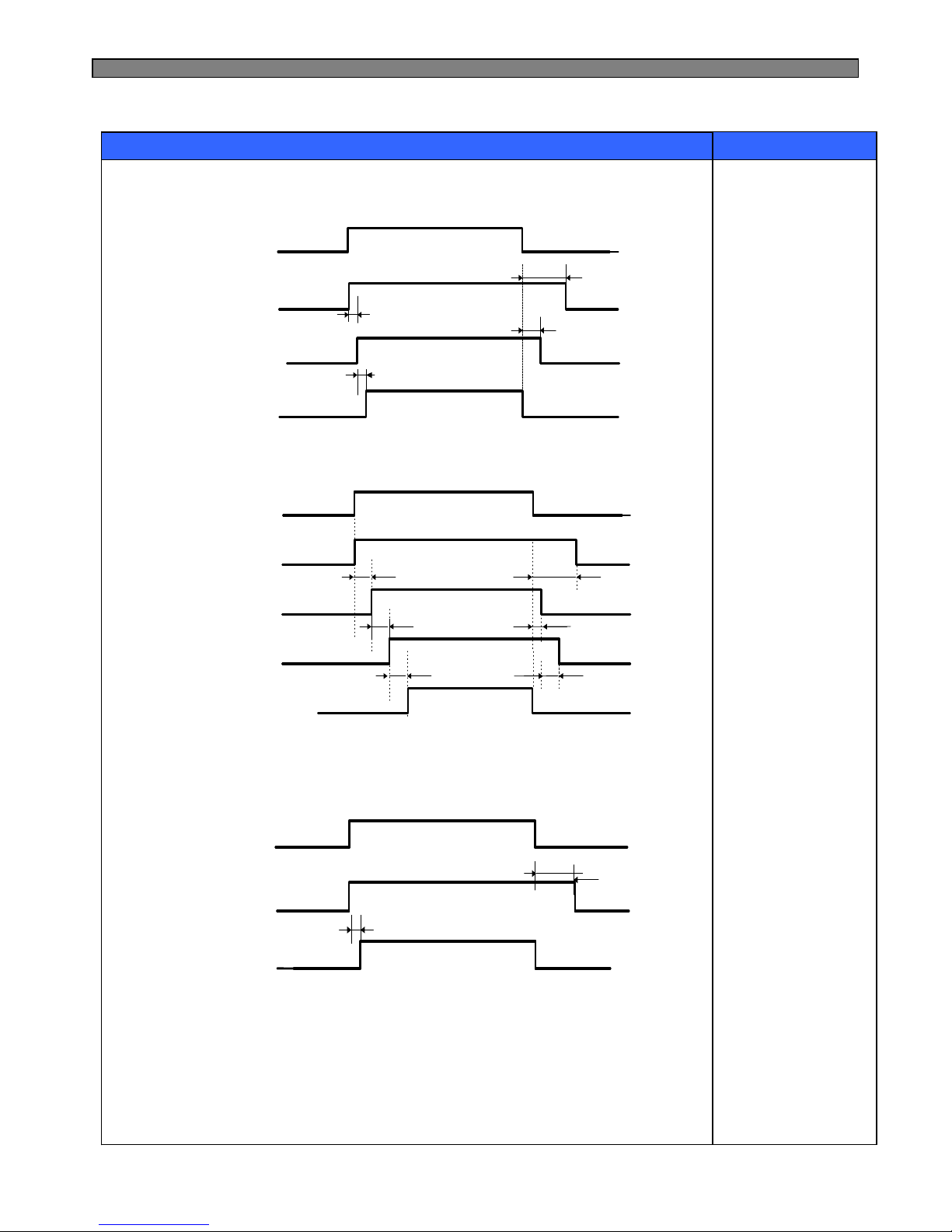
4) Control Flow & Timing Chart
① Crushed Ice
② Cubed Ice
③ Water
Delay time : A = 500ms, B = 500ms, C = 2.0s, D = 5.0s
D.P SW
D.P SW D.P SW
D.P SW
Gear Motor
Gear MotorGear Motor
Gear Motor
D.P Lamp
D.P LampD.P Lamp
D.P Lamp
D.P S/V
D.P S/V D.P S/V
D.P S/V
(Flap)
(Flap)(Flap)
(Flap)
D
A
A
C
D.P SW
D.P SW D.P SW
D.P SW
Cube S/V
Cube S/VCube S/V
Cube S/V
D.P S/V
D.P S/V D.P S/V
D.P S/V
(Flap)
(Flap) (Flap)
(Flap)
Gear Motor
Gear MotorGear Motor
Gear Motor
D.P Lamp
D.P LampD.P Lamp
D.P Lamp
A
C
A
A
B
D
D.P Lamp
D.P LampD.P Lamp
D.P Lamp
D.P SW
D.P SW D.P SW
D.P SW
Water S/V
Water S/VWater S/V
Water S/V
D
A
Page 35
34
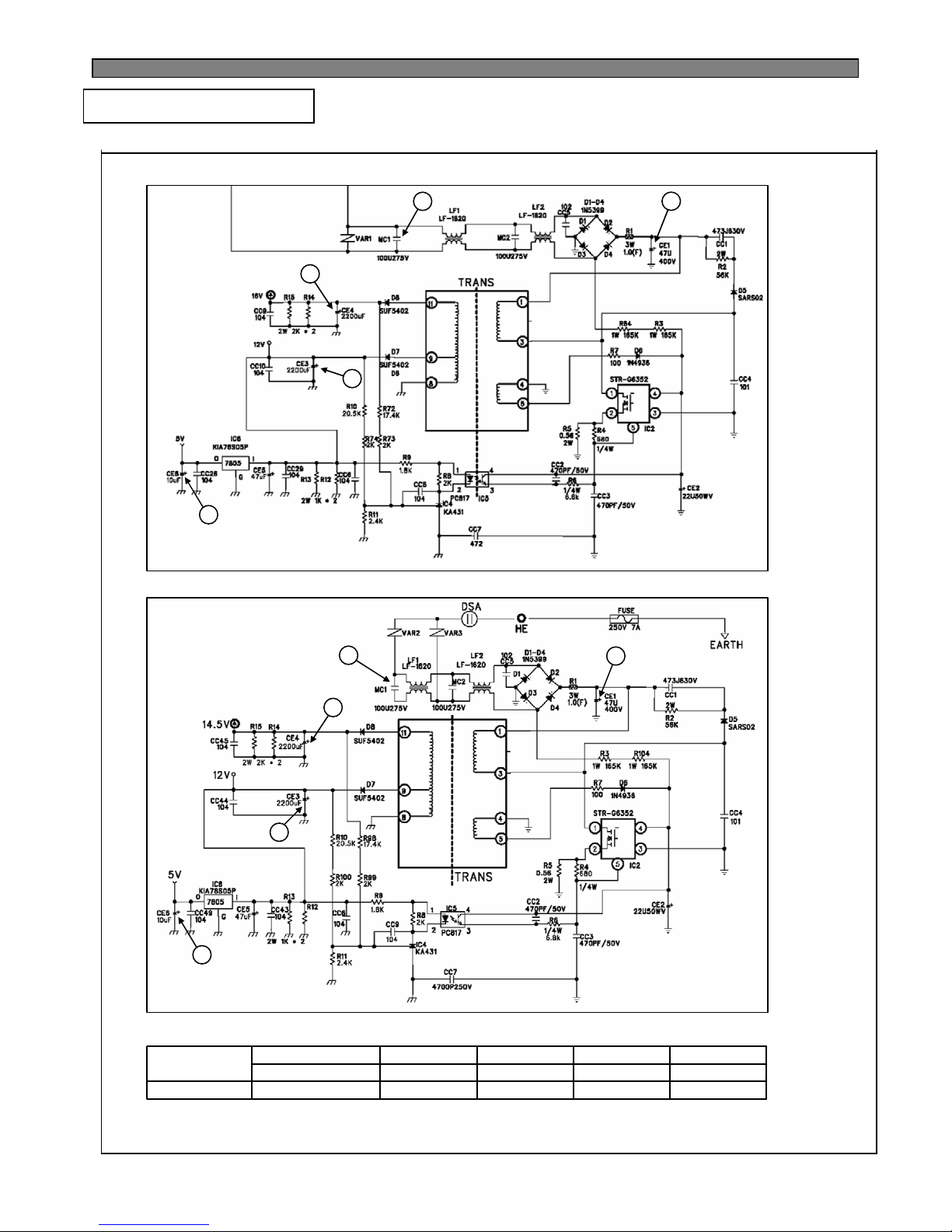
5-1. Power Circuit Diagram
5. CIRCUIT OPERATION
■ FRS(N)-U20IA
5Vdc14.5Vdc12Vdc310Vac230VdcVoltage
CE6CE4CE3CE1MC1
EDCBA
Parts
A
■ FRS(N)-U20DA/EA/FA/GA
B
D
C
E
A
B
C
D
E
※ Voltage of every part
※ Caution : Since high voltage (DC310V) is maintained at the power terminal, please take a measure after more
than 3minutes have passed after removing power cords in the abnormal operation of a circuit.
Page 36
35
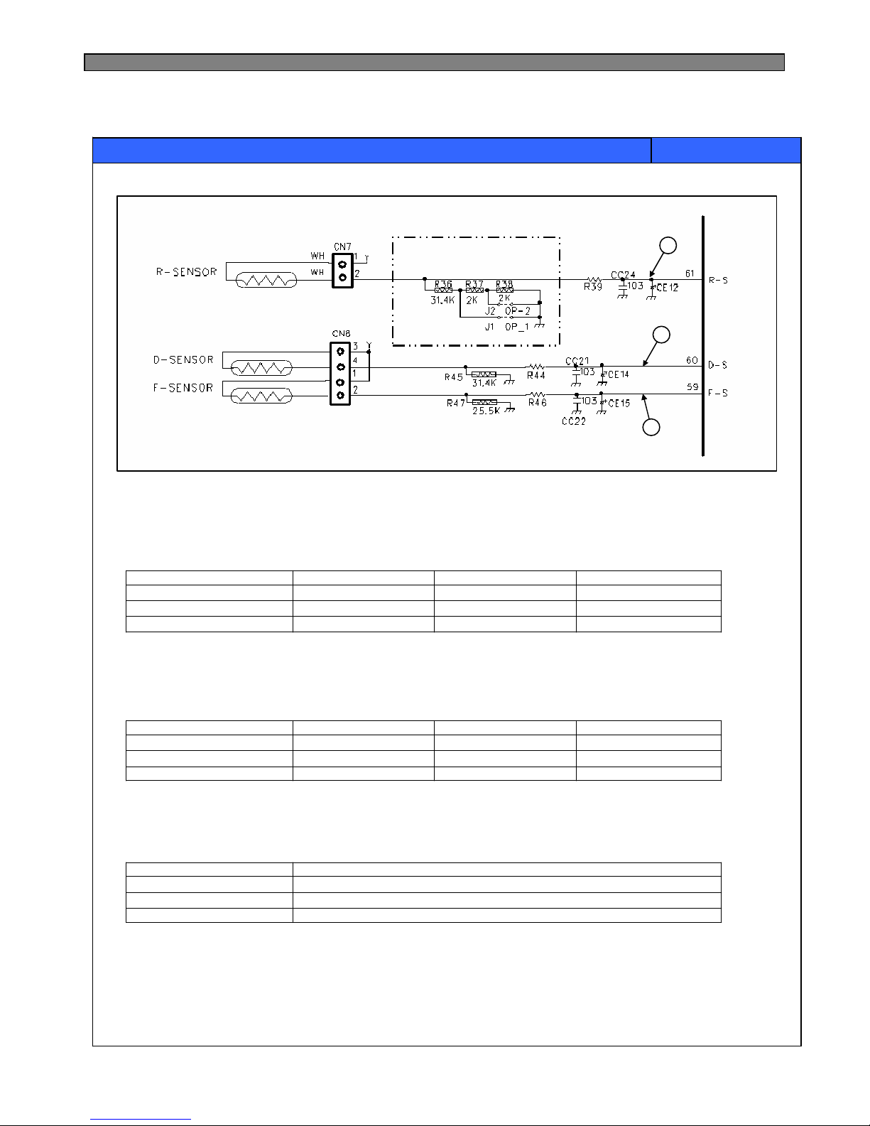
[F-sensor]
1) It senses the temperature of freezer compartment and control Comp., F-fan ON/OFF
2) How it works;
-19℃-16℃-11℃Working Temp.
≒3.24V
≒9.32㏀
Low ON
≒2.73V≒2.93VSensing Voltage
≒15.58㏀≒15.19㏀Resistance
High OFFMid OFFWorking Point
[R-sensor]
1) It senses the temperature of refrigerator compartment and control R-fan ON/OFF
2) How it works;
3.2℃5.2℃7.7℃Working Temp.
≒2.96V
≒23.33㏀
Low ON
≒2.72V≒2.83VSensing Voltage
≒24.76㏀≒24.05㏀Resistance
High OFFMid OFFWorking Point
[D-sensor]
1) It senses return point of defrosting heater.
2) How it works;
13℃Working Temp.
≒3.08V
≒22.56㏀
Return point of defrosting heater
Sensing Voltage
Resistance
Working Point
CONTENTS
REMARKS
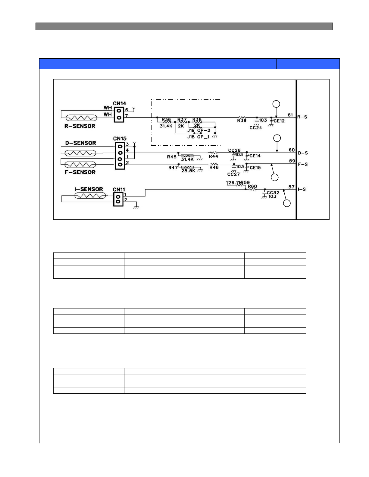
5-2. Function of Each Sensor
■ FRS(N)-U20IA
* In case temperature of refrigerator compartment is weak or insufficient though comp.
and R-fan operate in normal way;
1) Cut J1 on the M-PCB, then temp. is lowered 1.5℃ than [Mid OFF point]
2) Cut J1 and J2 on the M-PCB, then the temp, is lowered 3℃.
IC1
(MICOM)
Compensation of
R-sensor ON/OFF temp.
A
C
B
Page 37
36
CONTENTS
REMARKS
■ FRS(N)-U20DA/EA/FA/GA
[F-sensor (A)]
1) It senses the temperature of freezer compartment and control Comp., F-fan ON/OFF
2) How it works;
-19℃-16℃-11℃Working Temp.
≒3.24V
≒9.32㏀
Low ON
≒2.73V≒2.93VSensing Voltage
≒15.58㏀≒15.19㏀Resistance
High OFFMid OFFWorking Point
[R-sensor (B)]
1) It senses the temperature of refrigerator compartment and control R-fan ON/OFF
2) How it works;
3.2℃5.2℃7.7℃Working Temp.
≒2.96V
≒23.33㏀
Low ON
≒2.72V≒2.83VSensing Voltage
≒24.76㏀≒24.05㏀Resistance
High OFFMid OFFWorking Point
[D-sensor (C)]
1) It senses return point of defrosting heater.
2) How it works;
13℃Working Temp.
≒3.08V
≒22.56㏀
Return point of defrosting heater
Sensing Voltage
Resistance
Working Point
* In case temperature of refrigerator compartment is weak or insufficient,
though comp. and R-fan operate in normal way;
1) Cut J18 on the M-PCB, then temp. is lowered 1.5℃ than [Mid OFF point]
2) Cut J18 and J19 on the M-PCB, then the temp, is lowered 3 ℃
IC1
(MICOM)
Compensation of
R-sensor ON/OFF temp.
A
B
C
D
Page 38
37
1. Circuit Diagram
#14≒12V
#12≒12V
#10≒12V
#14≒0.7V
#12≒0.7V
#10≒0.7V
IC7#3≒0V#3≒5.0VRelay 3Louver Heater
OFF ConditionON Condition
#5≒0V#5≒5.0VRelay 5D-Heater
Relay 1
Control Mode
Method
IC7
IC ULN2004
Output pin
#1≒5.0V
MICOM Port
#1≒0V
MICOM Port
Comp
IC ULN2004
Output pin
Control
CONTENTS
REMARKS
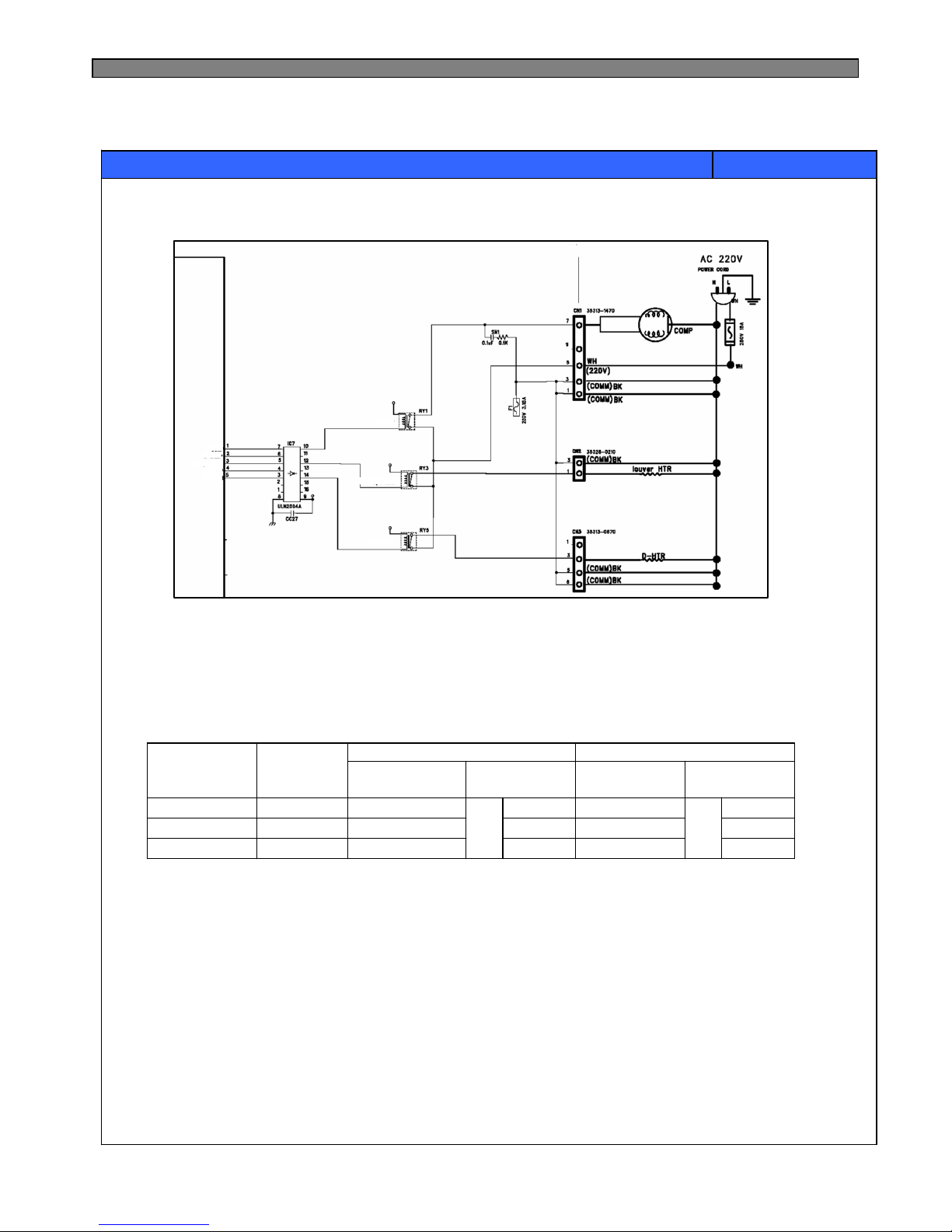
5-3. Relay Function
■. FRS(N)-U20IA
2. How it works;
IC1
(MICOM)
Comp
D-Heater
Louver Heater
D-Heater
Louver Heater
Comp
R-Lamp
F-Lamp
Page 39
38
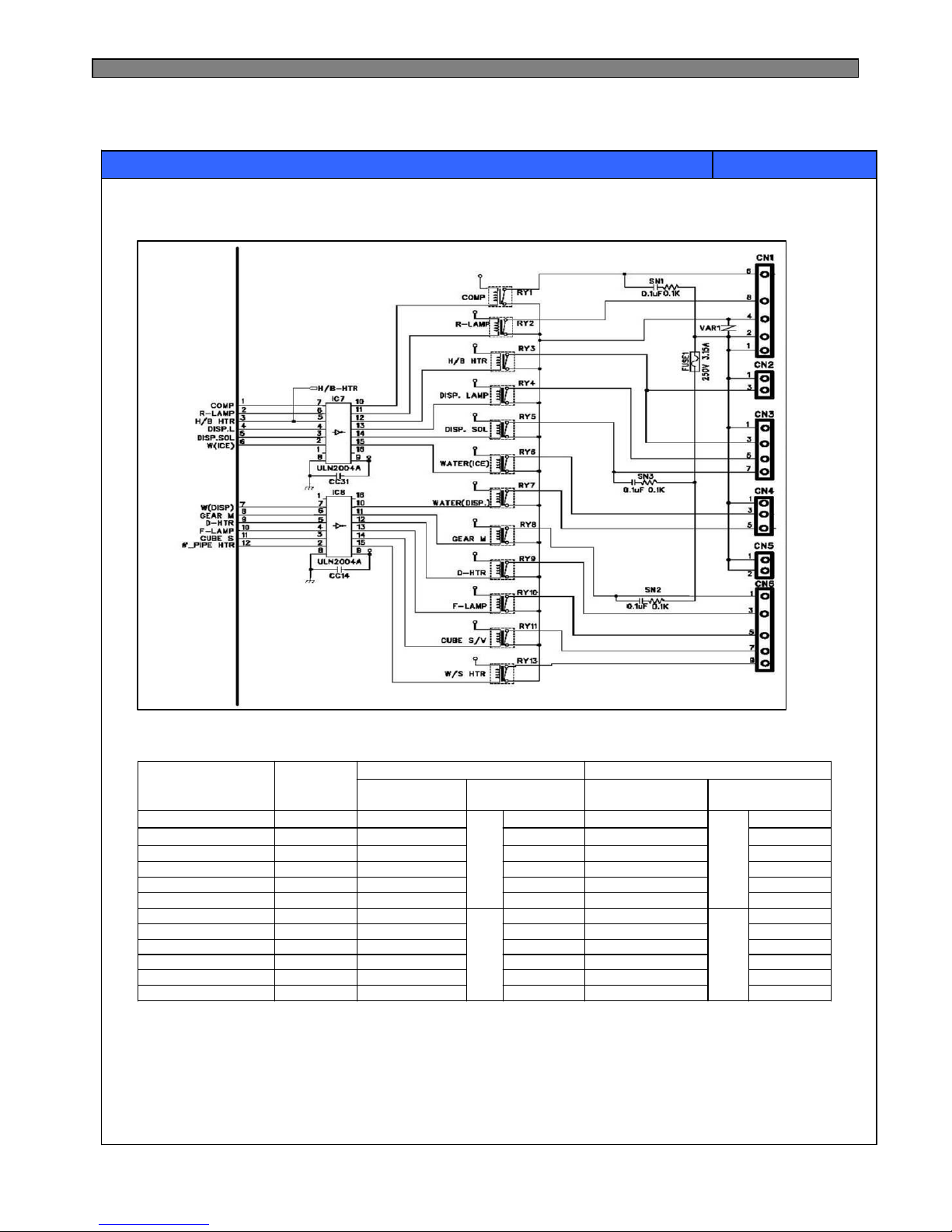
1. Circuit Diagram
CONTENTS
REMARKS
■ FRS(N)-U20DA/EA/FA/GA
2. How it works;
#15≒12V
#14≒12V
#13≒12V
#12≒12V
#11≒12V
#10≒12V
#15≒12V
#14≒12V
#13≒12V
#12≒12V
#11≒12V
#10≒12V
#15≒0.7V
#14≒0.7V
#13≒0.7V
#12≒0.7V
#11≒0.7V
#10≒0.7V
#15≒0.7V
#14≒0.7V
#13≒0.7V
#12≒0.7V
#11≒0.7V
#10≒0.7V
OFF ConditionON Condition
#3≒0V#3≒5.0VRelay 3H/B Heater
IC8
#7≒0V
IC8
#7≒5.0VRelay 7Water (Dispenser)
#6≒0V#6≒5.0VRelay 6Water (Ice)
#5≒0V#5≒5.0VRelay 5Dispenser-Solenoid
#4≒0V#4≒5.0VRelay 4Dispenser-Lamp
#9≒0V#9≒5.0VRelay 9D-Heater
#8≒0V#8≒5.0VRelay 8Geared-Motor
#10≒0V#10≒5.0VRelay 10F-Lamp
#11≒0V#11≒5.0VRelay 11Cube-Solenoid
Relay 12
Relay 2
Relay 1
Control Mode
Method
IC7
IC ULN2004
Output pin
#12≒5.0V
#2≒5.0V
#1≒5.0V
MICOM Port
#12≒0V
#2≒0V
#1≒0V
MICOM Port
IC7
Comp
IC ULN2004
Output pin
Water Pipe Heater
R-Lamp
Control
IC1
(MICOM)
D-Heater
Louver Heater
Comp
R-Lamp
F-Lamp
Page 40
39
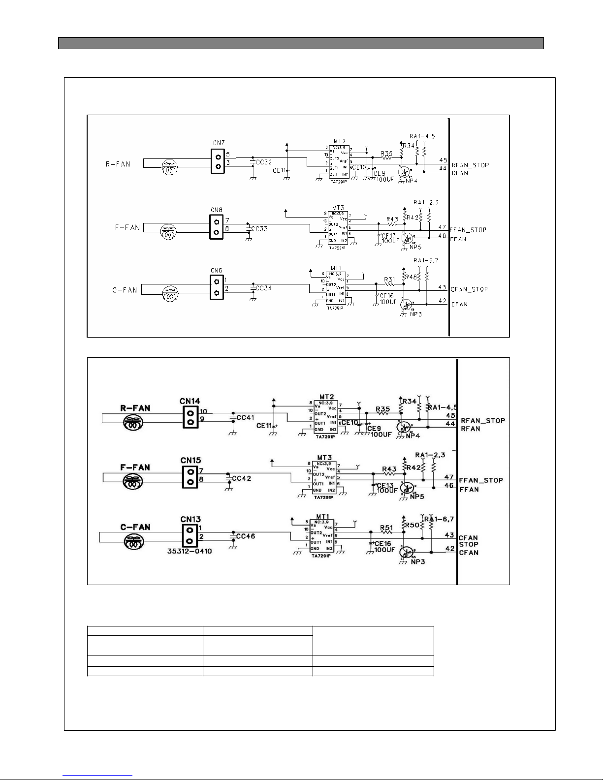
5-4. Fan Function
■ FRS(N)-U20IA
■ FRS(N)-U20DA/EA/FA/GA
- Vref is the reference voltage for the adjustment of the output voltage by the voltage
distribution of Vs (Maximum output voltage), and the output voltage applied to the fan
is determined by the PWM control using the software.
2. Explanation for the operation
* TA7291P is the drive IC for the only DC motor, and used for control of the fan motor
* One input and output is used for the control of the fan motor
Motor IC No.2 Pin
(R:MT2/F:MT3/C:MT1)
Motor IC No.5 Pin
(R:MT2/F:MT3/C:MT1)
Low
High
Output
StopLow
13VHigh
Remark
Input
1. Circuit Diagram
Page 41
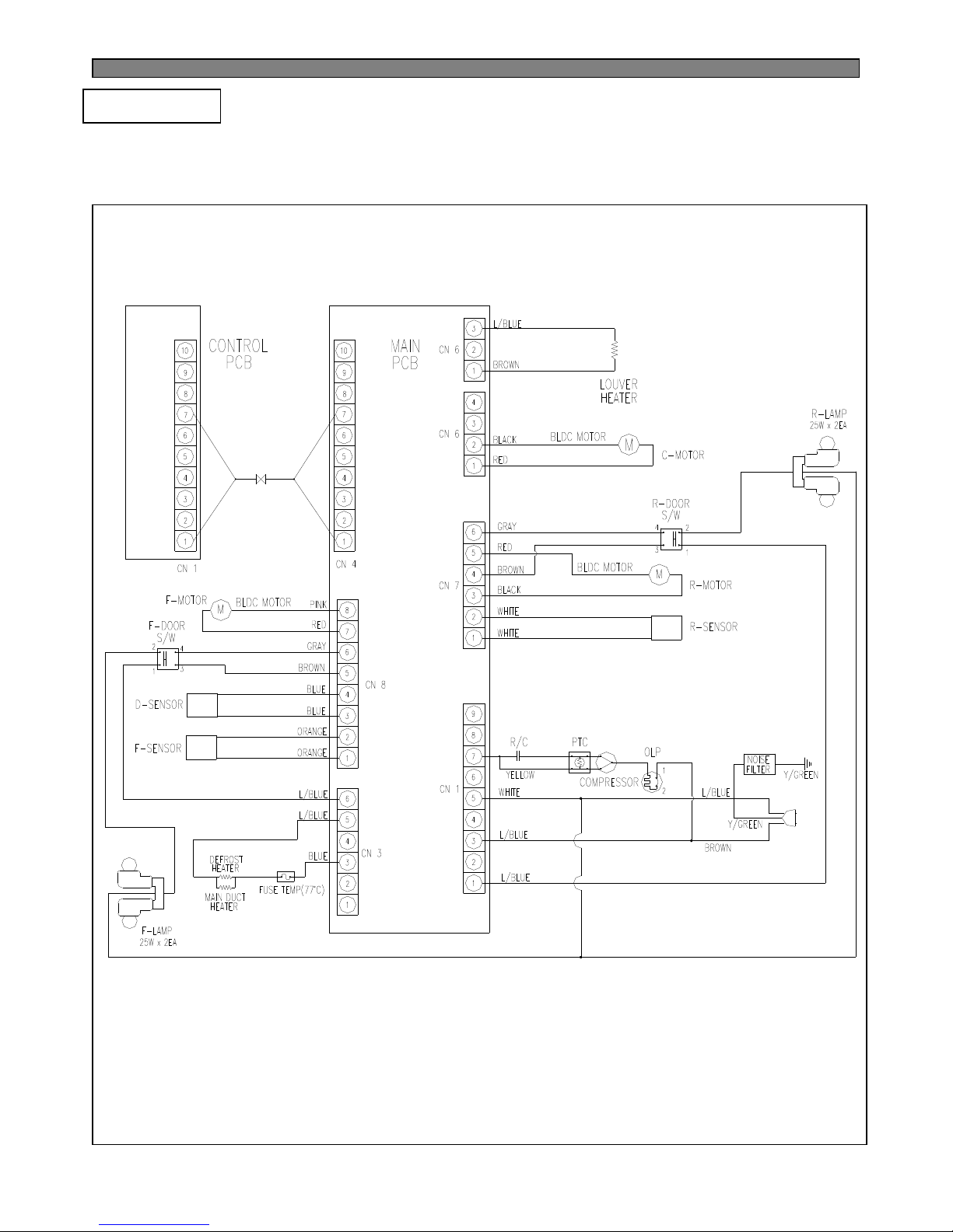
40
6-1. Wiring Diagram
6. DIAGRAM
■ FRS(N)-U20IA
Page 42
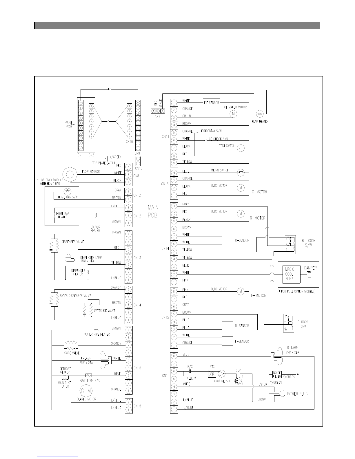
41
■ FRS(N)-U20DA / EA / FA / GA
Page 43
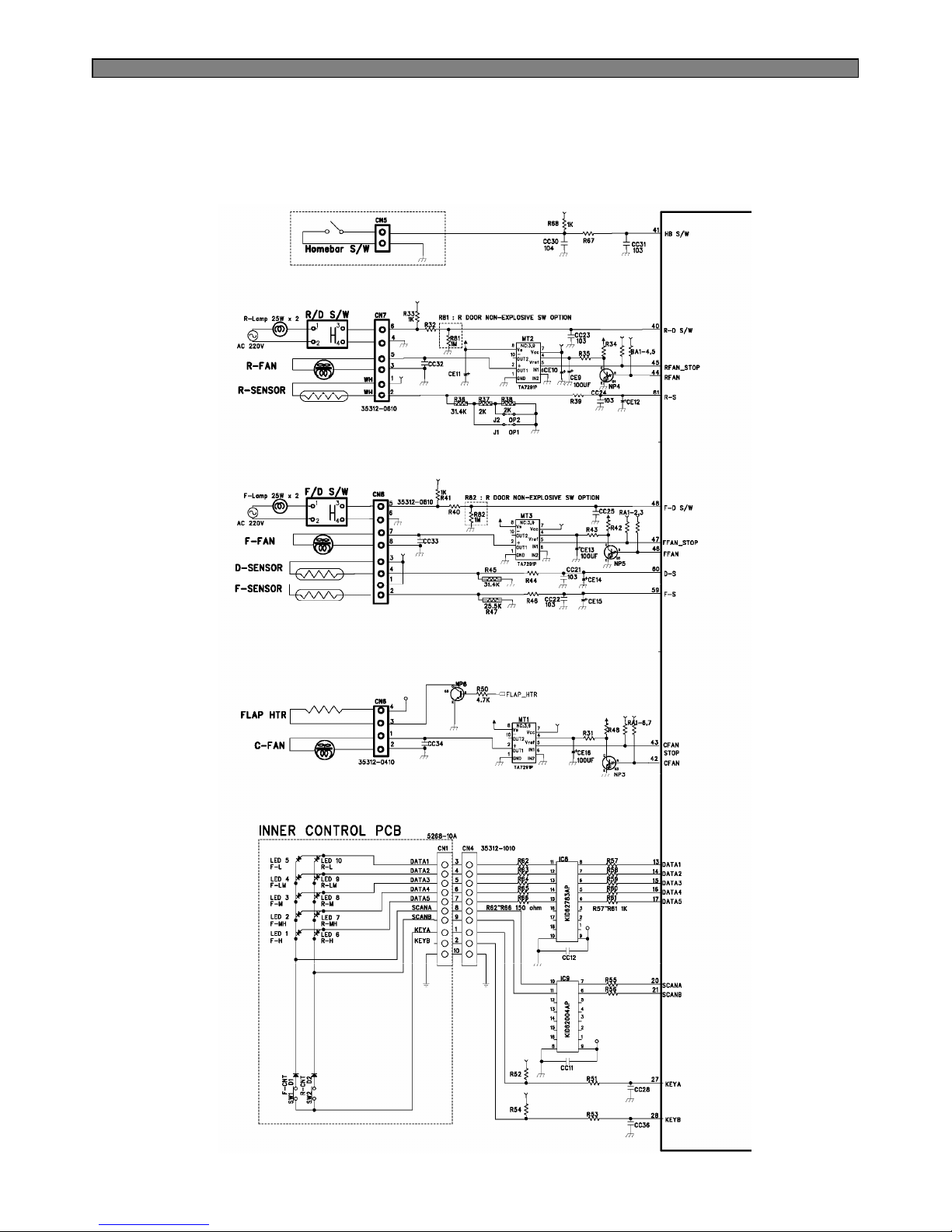
42
6-2. Circuit Diagram of Main PCB
■ FRS(N)-U20IA
Page 44
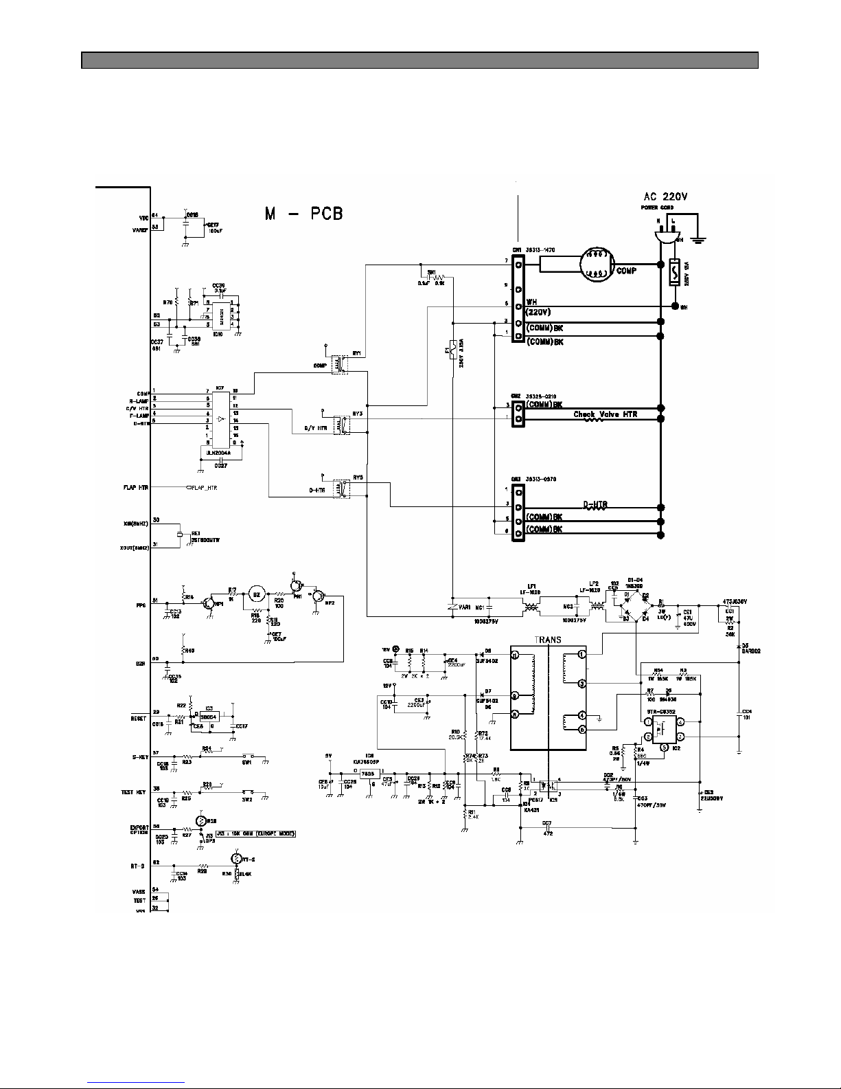
43
Page 45
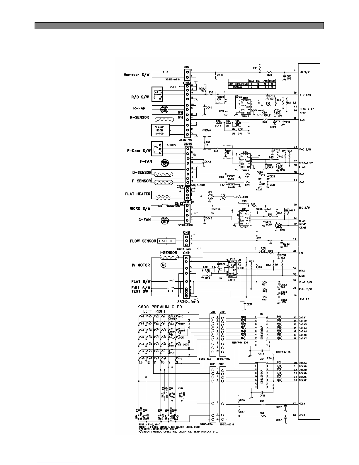
44
■ FRS(N)-U20DA / EA / FA / GA
Page 46
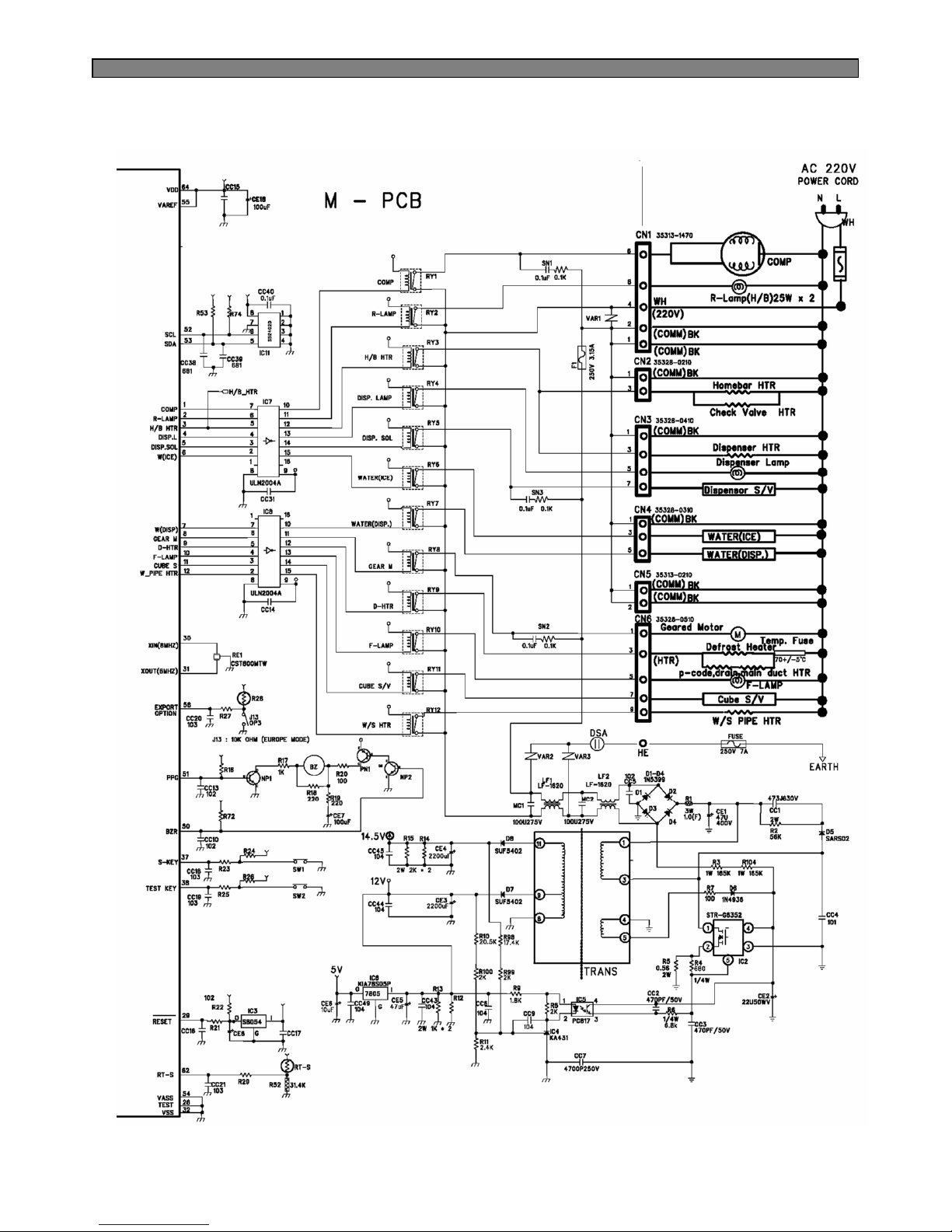
45
Page 47
46
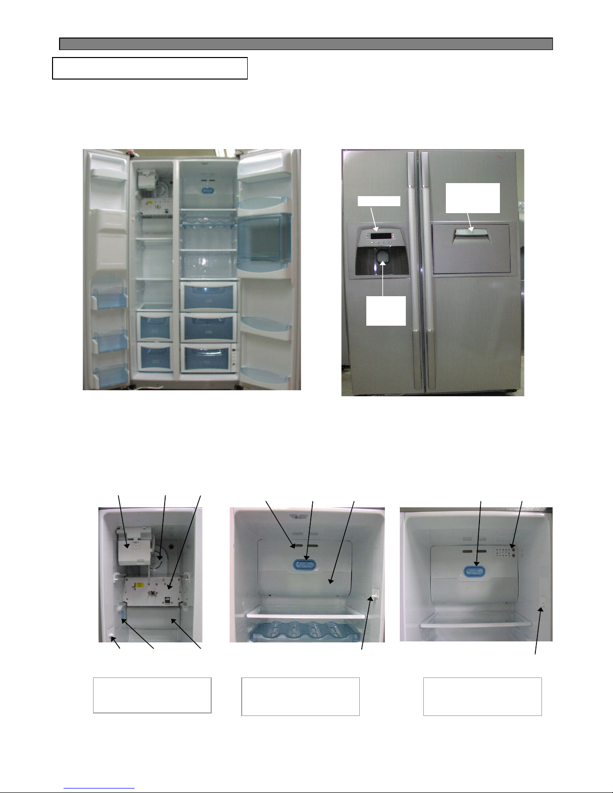
7. COMPONENT LOCATE WIEW
7-1. Front View
F-Sensor
Automatic
Ice Maker
Geared
Motor
R-Sensor
R-Sensor
Inner
Controller
F-Door
Switch
R-Door
Switch
R-Door
Switch
Freezer Compartment
(FRS(N)-U20DA)
Front PCB
Dispense
r
Button
Home bar
Door
(Option)
F-Lamp
F-Fan
Motor
R-Lamp
R-Fan
Motor
7-2. Inner View
Refrigerator
Compartment
(FRS(N)-U20DA)
Refrigerator
Compartment
(FRS(N)-U20IA)
Page 48
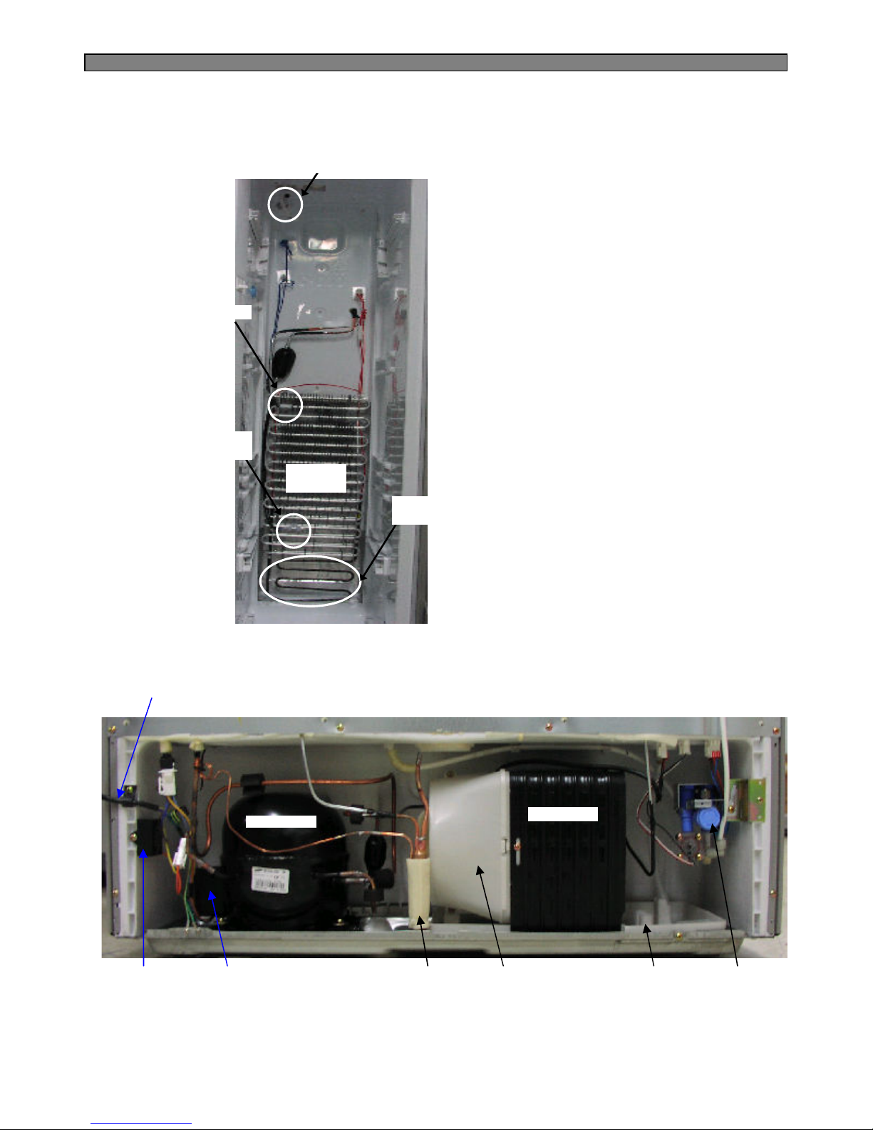
47
D-Sensor
Temp
Fuse
Defrost
Heater
Water Pipe
Evaporato
r
Compressor
Condenser
Dryer
Running
Capacitor
OLP
& PTC
Water
Valve
Condenser
Fan-Motor
Tray Drip
Power cord
7-3. Evaporator
7-4. Machine Compartment
Page 49
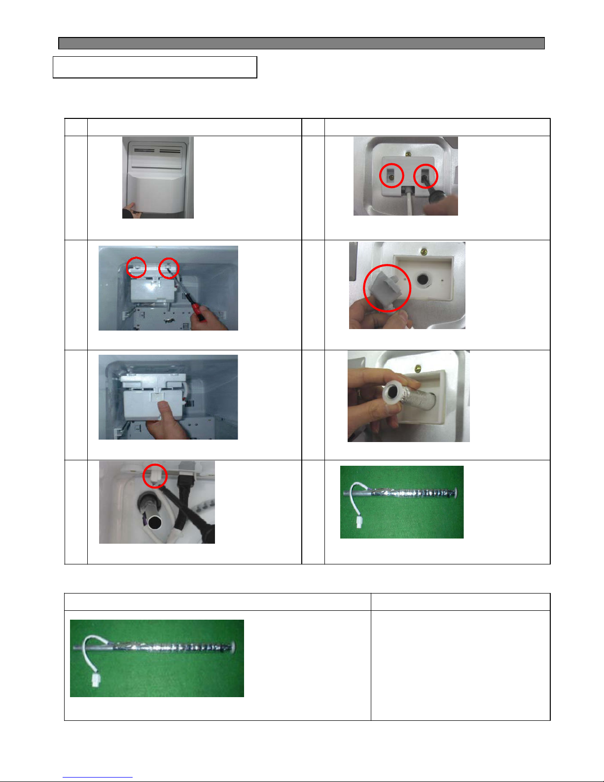
48
NO
DISASSEMBLING PROCEDURE NO DISASSEMBLING PROCEDURE
1 5
2 6
3 7
4 8
▷Pull forward Ice Storage Case
▷Remove 2 screws at the Cove
Guide Cab W/Tube A.
▷Remove 2 screws. ▷Disassemble Cover Guide Cab W/Tube A
▷Pull forward Ice Maker. ▷Pull forward Hose Ice Maker Tube As.
▷Remove Water Hose Heater's 2P housing.
▷Check Hose Ice Maker Tube As.
2) How to check Hose Ice Maker Tube As.
How to check CRITERION
▷Measure the resistance
of two wire
▷Good: 9680Ω(±8%)
(8900 ~ 10456Ω)
▷If defective, change
8. HOW TO CHECK EACH PARTS
8-1. Hose Ice Maker Tube Assembly
1) Disassembling Procedure
Page 50
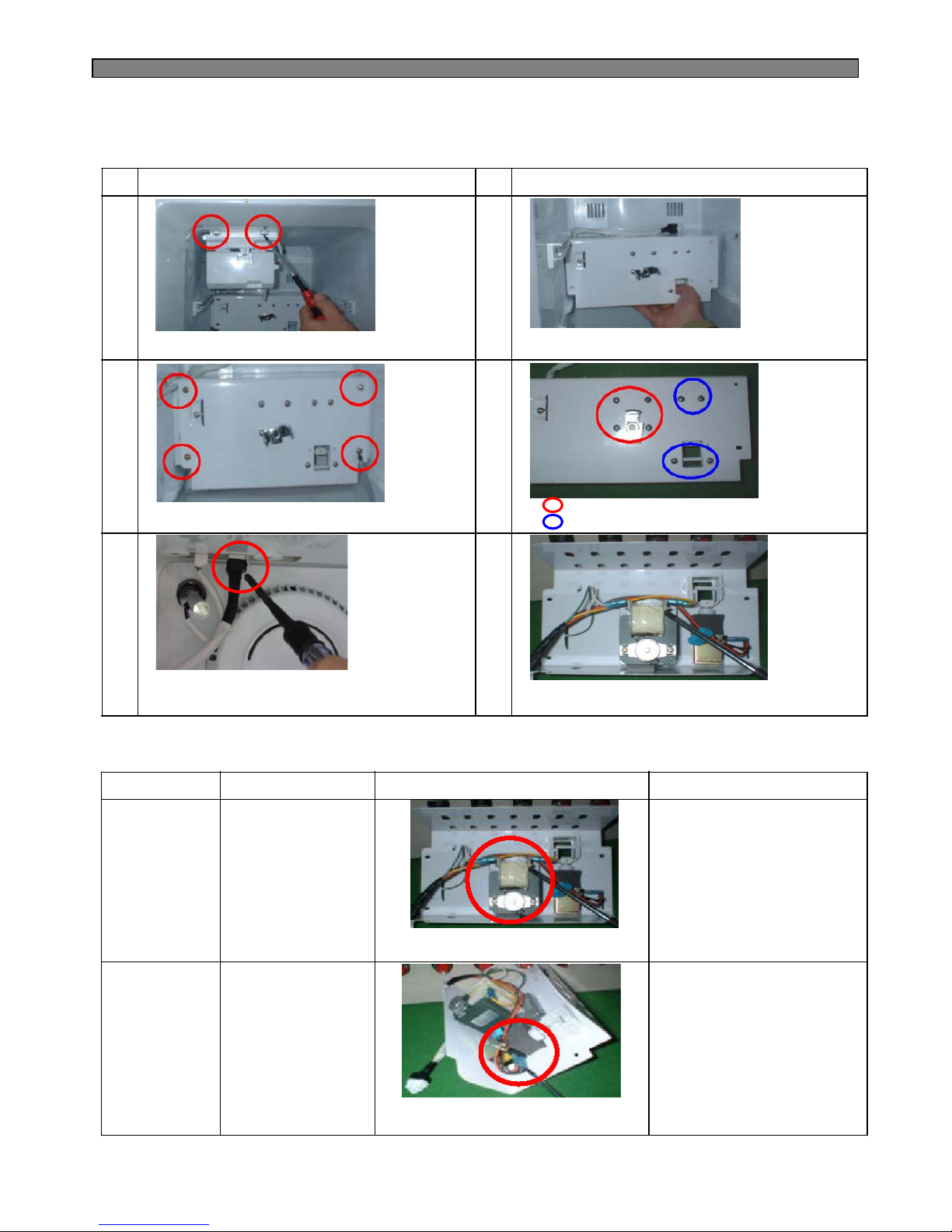
49
NO
DISASSEMBLING PROCEDURE NO DISASSEMBLING PROCEDURE
1 4
2 5
3 6
▷Remove 2 screws.
▷Pull forward Bracket Geared Motor.
▷Unscrew (4 points).
▷Separate 6 pin housing of Bracket
Geared Motor from the top connector.
▷Check Solenoid Valve and Geared Motor.
2) How to Check Hose Ice Maker Tube Assembly
SPEC. CRITERION
▷GOOD : 11.3Ω(±10%)
(10.8 ~ 12.7Ω)
▷DEFECTIVE ;
Change the Geared Motor.
PARTS HOW TO CHECK
▷GOOD : 145Ω(±8%)
(133 ~ 156Ω)
▷DEFECTIVE ;
Change the Cube Sol Valve.
▷Check resistance value of
2 terminals with a Multi Tester.
▷SPEC. NAME
:DAG-6502DEC
▷VOLTAGE
:220/240V,50Hz
▷SPEC. NAME
:Cube SN8
▷VOLTAGE
:220/240V,50Hz
▷Check resistance value of
2 terminals with a Multi Tester.
Geared Motor
Cube Sol Valve
8-2. Bracket Geared Motor Assembly
1) Disassembling Procedure
Unscrew (red 4 screws).
Unscrew (blue 4 screws).
Page 51
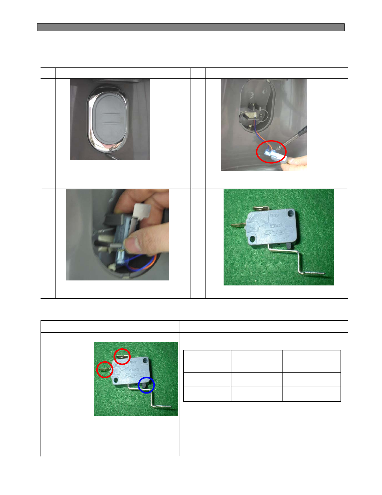
50
NO
DISASSEMBLING PROCEDURE NO DISASSEMBLING PROCEDURE
1 3
2
▷ Insert (-) screw driver into bottom hole of
Dispenser Button Guide.
Pull up forward to remove the guide.
(Be careful not to damage guide surface.)
▷ Remove Micro switch.
2) How to Check Micro Switch
CRITERION
▷GOOD :
▷DEFECTIVE :
Change Micro Switch.
PARTS HOW TO CHECK
SPEC. NAME
: VP333A-OD-8
VOLTAGE
:125V,3A
8-3. Dispenser Micro Switch
1) Disassembling Procedure
▷Check both terminals
(red circle) with a Multi Tester
(Tester Mode : Resistance (Ω).
Tact Switch
(Blue Circle)
Terminals
(Red circle)
Tester Result
(Resistance Mode)
ON (Close) Connected Some Value
OFF (Open) Disconnected No value (0)
▷Check Micro Switch.
▷Separate wire connectors
from Micro Switch.
4
Page 52
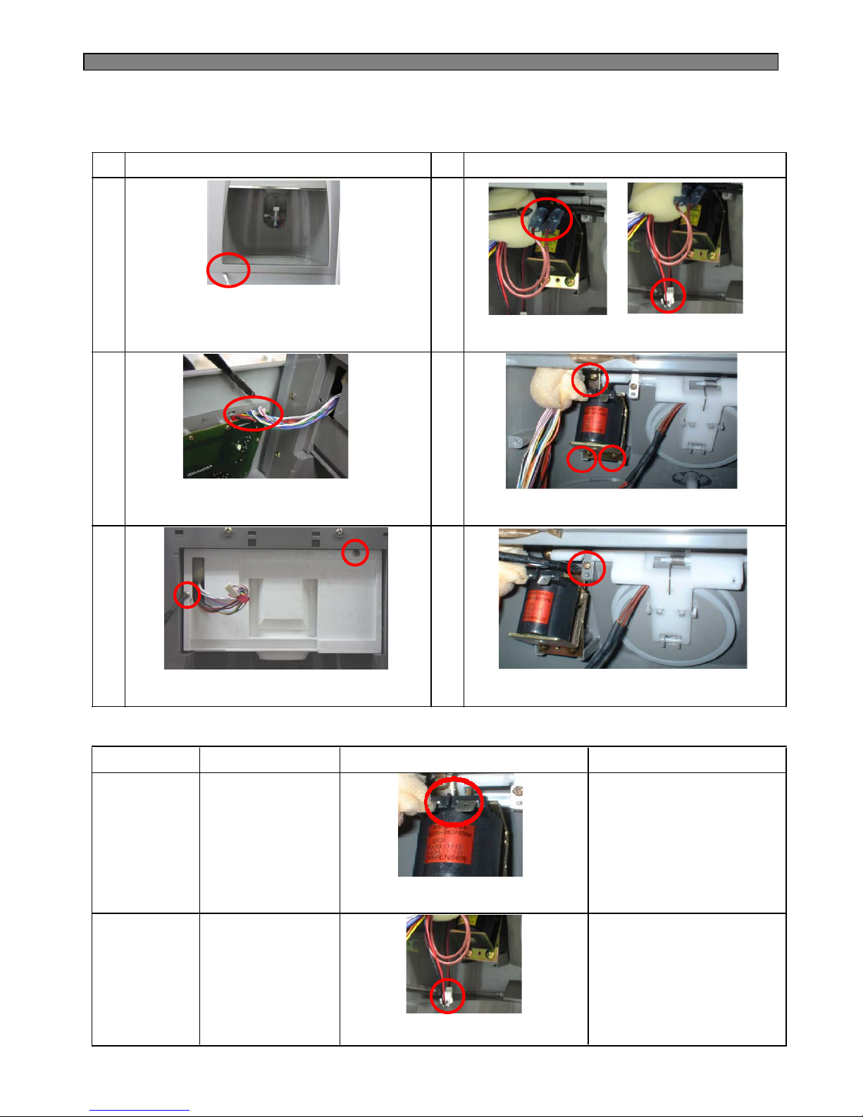
51
NO
DISASSEMBLING PROCEDURE NO DISASSEMBLING PROCEDURE
1 4
3 6
▷ Separate 2 housings of 10P / 7P
from Front PCB.
(Do not hold only wires to pull out.)
▷Unscrew (3 points) to remove Sol Valve.
▷Unscrew (2 points) to remove Box
Dispenser Shut.
▷Unscrew (1 point) to remove Cover Ice Flap.
2) How to Check Micro Switch
8-4. Dispenser Solenoid Valve
1) Disassembling Procedure
SPEC. CRITERION
▷ Good : 215Ω(±10%)
(193 ~ 236Ω)
▷DEFECTIVE : 0
Change Sol Valve.
PARTS HOW TO CHECK
▷GOOD : 96Ω(±8%)
(88 ~ 104Ω)
▷DEFECTIVE ;
Change Flap Heater AS.
▷SPEC. NAME
:SOL2003-01B
▷VOLTAGE
:220/240V,50Hz
▷VOLTAGE
:DC 12V,1.5W
▷Check resistance value of
both terminals with a tester.
Dispenser
Sol Valve
Flap Heater
Assembly
▷Check resistance value of
both terminals with a tester.
2 5
▷ Insert (-) screw driver into bottom left groove
of Cover Dispenser Box. Pull forward with a
snap.(Be careful not to damage cover and
door surface.)
▷Separate 2 terminals from Sol Valve and
2P Housings from Cover Ice Flap.
Page 53
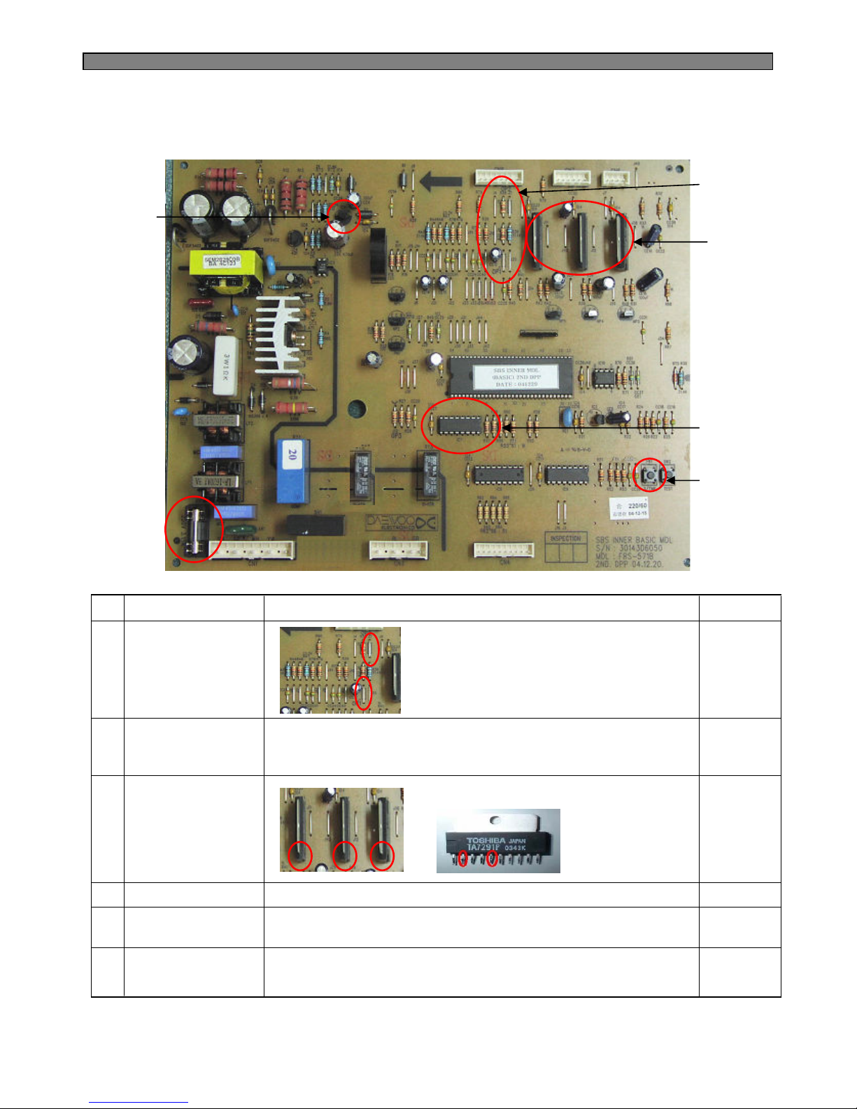
52
8-5. Main PCB
1
2
3
4
5
6
ITEM REMARK
NO CHECK POINT
Compensation of
Weak Refrigeration
→Making R-temp
cooler
1
* Used when making R-temp. down
to compensate for weak refrigeration
without changing FCP temp. setting.
▷Cutting of J1 ; down by 1.5℃
▷Cutting of J1, J2 ; down by 3℃
Relay Power
Controller
2
* To check normal voltage of each electrical devices
to & from Mi-com.
▷Check input & output voltage of MICOM and IC7
Fan Power
Controller
3
* To check input & output voltage of Fan
▷#2 : Input
▷#5 : Output
Electric Current Fuse
4 * To check when each device does not work (250V,3.15A)
Time Shortening
Switch
5 * To shorten time in PCB checkup
(Pressing 1 time is regarded as 1 minute has passed.)
Regulator IC(5V)6 * To check voltage of MICOM and IC
Voltage check of IC#6 (Input :12V,Output : 5V)
J1
J2
■ FRS(N)-U20IA
F
R
C
Page 54
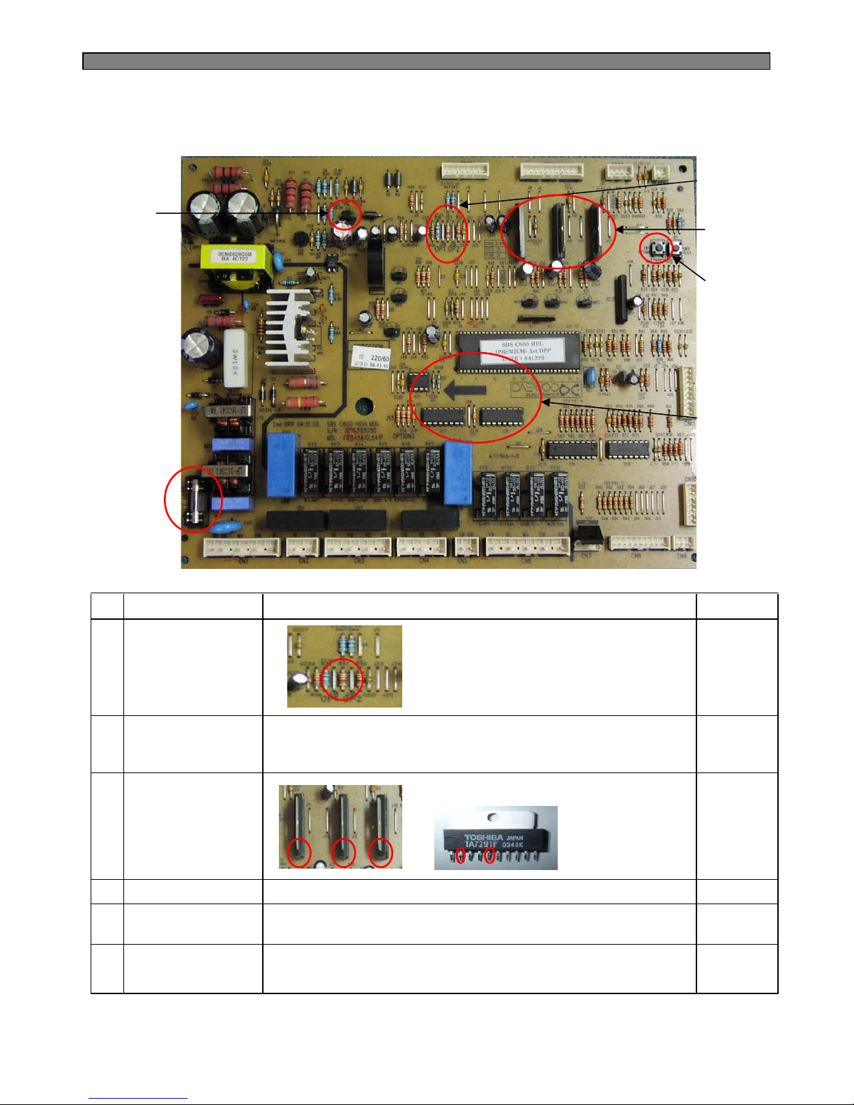
53
ITEM REMARK
NO CHECK POINT
Compensation of
Weak Refrigeration
→Making R-temp
cooler
1
* Used when making R-temp. down
to compensate for weak refrigeration
without changing FCP temp. setting.
▷Cutting of J18 ; down by 1.5 ℃
▷Cutting of J18, J19 ; down by 3℃
Relay Power
Controller
2 * To check normal voltage of each electrical devices
to & from Mi-com.
▷Check input & output voltage of MICOM and IC7, 8.
Fan Power
Controller
3
* To check input & output voltage of Fan
Electric Current Fuse
4 * To check when each device does not work (250V,3.15A)
Time Shortening
Switch
5 * To shorten time in PCB checkup
(Pressing 1 time is regarded as 1 minute has passed.)
Regurator IC(5V)
6 * To check voltage of MICOM and IC
Voltage check of IC#6 (Input :12V,Output : 5V)
1
2
3
4
5
6
J18,19
■ FRS(N)-U20DA/EA/FA/GA
▷#2 : Input
▷#5 : Output
F
R
C
Page 55
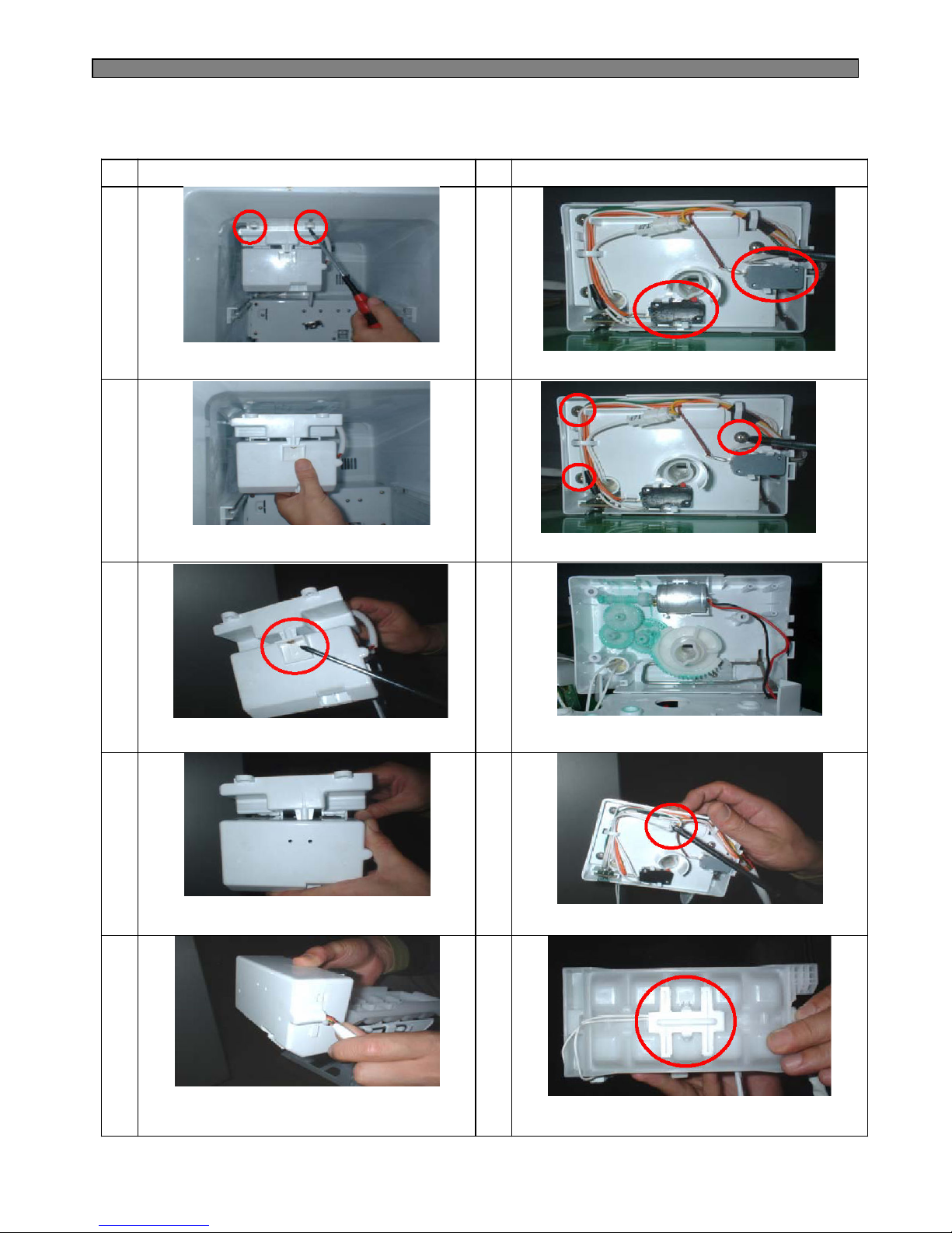
54
NO
DISASSEMBLING PROCEDURE NO DISASSEMBLING PROCEDURE
1 6
3 8
▷ Pull forward ice maker. ▷Unscrew (3 points) Plate Gear Fixture.
▷Unscrew Fixture of Frame Ice Maker.
▷ Check if ice dropping motor is normal (OK).
8-6. Ice Maker
1) Disassembling Procedure
2 7
▷ Remove 2 screws on top front of ice maker.
▷Remove full ice sensing switch and level switch.
4 9
▷Separate Ice Maker Assembly from
Frame Ice Maker.
▷Remove 2 pin housing from Plate Gear Fixture.
5 10
▷ Separate Cover I/M (A) from Cover I/M (B)
with a (-) screw driver.
▷ Remove I-sensor (ice sensor) from
Case Icing As.
* Follow the reverse order when assembling.
Page 56
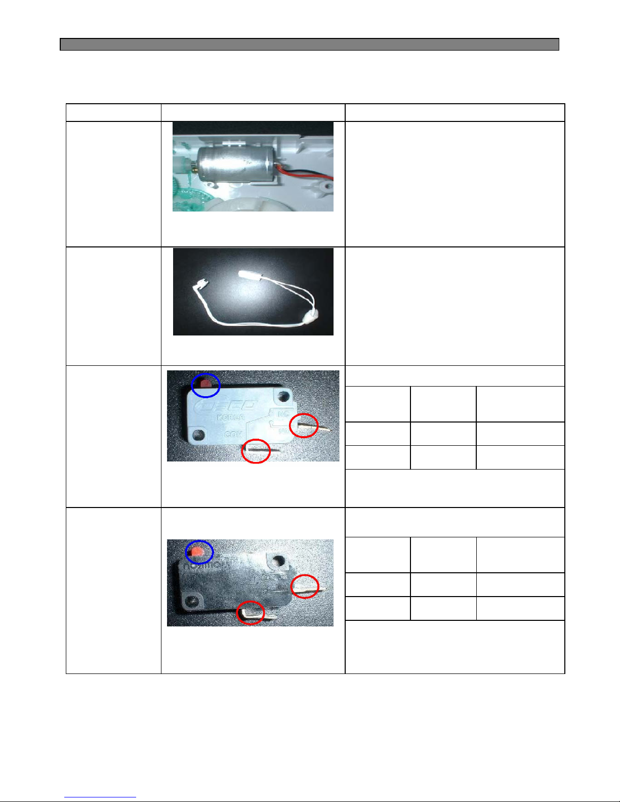
55
PARTS HOW TO CHECK CRITERION
Ice Dropping Motor
2) How to Check Ice Maker
▷ Check resistance value of 2 wires
with a Multi Tester.
▷ GOOD : RS-360RH-14250
: 6 ~ 14Ω
▷ DEFECTIVE :
Change the motor.
I-Sensor
(Ice Sensor)
▷ Check resistance value of 2 wires
with a Multi Tester.
▷ GOOD : 4.4 ~ 50kΩ
(It depends on surround temp.)
▷ DEFECTIVE :
Change the sensor.
Full Ice
Sensing Switch
▷ Check resistance value of 2 terminals
with a Multi Tester.
▷ GOOD :
▷ DEFECTIVE :
Change the switch.
Level Switch
▷ Check resistance value of 2 terminals
with a Multi Tester.
▷ GOOD :
▷ DEFECTIVE :
Change the switch.
Tact Switch
(Blue Circle)
Terminals
(Red circle)
Tester Result
(Resistance Mode)
ON (Close) Connected Some Value
OFF (Open) Disconnected No value (0)
Tact Switch
(Blue Circle)
Terminals
(Red circle)
Tester Result
(Resistance Mode)
ON (Close) Connected Some Value
OFF (Open) Disconnected No value (0)
Page 57
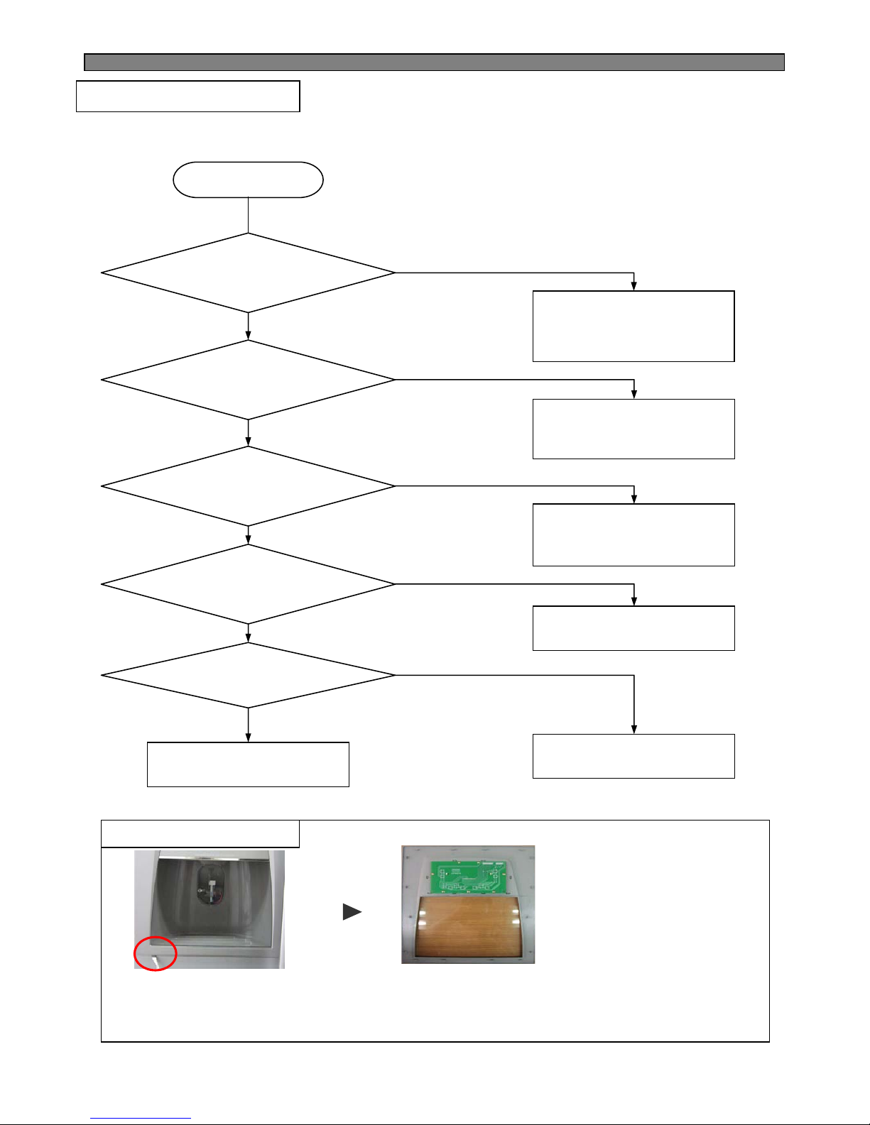
56
1) Insert a flat tip driver into the left down groove of panel frame and snap it out smoothly.
2) Separate 2 housings of 10P / 7P from Front PCB. (Do not hold only wires to pull out.)
3) Unscrew (7 points) to remove Front PCB.
* Follow the reverse order when assembling.
※ How to replace Front PCB
Change the Main Fuse
(AC250V 15A)
(In the left side of
machine compartment)
Start
Power cord or Fuse
is disconnected ?
1’st power of SMPS
is on?
Main PCB Fuse is
disconnected?
Voltage
(DC12V/14.5V/5V) on
Main PCB is OK?
Wire connection
of F-PCB is OK?
Check power Cord connection
from machine compartment and
to CN1 of M-PCB.
Change F-PCB AS.
Change Main PCB
Change the Fuse
(AC250V 3.15A)
(on the Main PCB)
Y
N
N
Y
N
Y
Y
N
Y
N
Checkup and connect
F-PCB wires.
9-1. Faulty Start (F/R lights OFF , F-PCB Power OFF)
※ Refer to the 5-1.
(Power circuit diagram)
9. TROUBLE DIAGNOSIS
Page 58
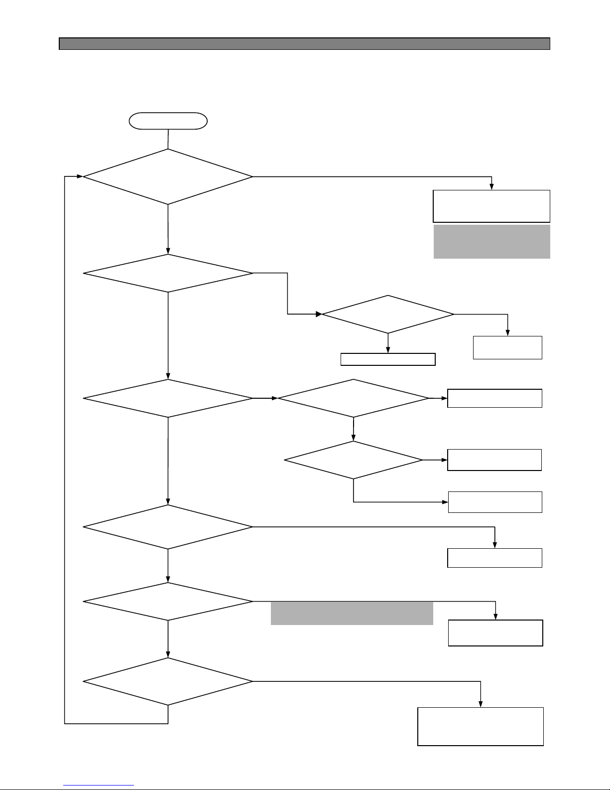
57
Refer to error display
in operation and function
Start
Change the
Comp.
Change Fuse. Temp
Y
N
N
Y
N
Y
Y
N
Y
N
Change OLP/PTC
Change F/C-Motor
Change M-PCB
Check lead wire
Change the
Defrost Heater
Check ice formation on Eva.
And if refrigerant leak
is found, repair it.
N
N
Y
Y
Y
N
N
Defrost Heater : 192W (252 Ω)
※ Left-lower side of Evaporator
(4
th
pipe from buttom)
OLP/PTC
is OK?
Does Comp.
work?
Any Error code
on F-PCB?
F/C-Motor
works OK?
F/C-Motor
is OK?
Wiring connection
Is OK?
Temp. Fuse
Is OK?
Defrost Heater
Is Ok?
Ice formation on Eva.
Is OK?
Y
9-2-1. Freezing failure . (Foods are not frozen / cold.)
9-2. Freezer Compartment
※※※※ Refer to the 4-10.
(Error Display)
Page 59
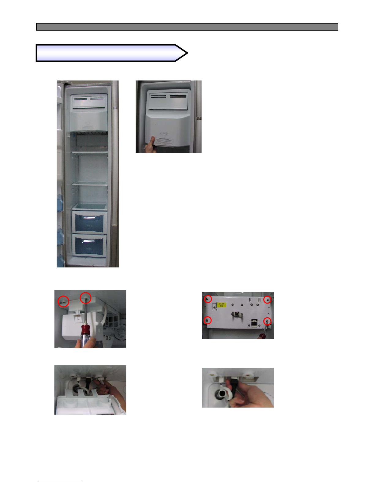
58
1) Remove foods.
2) Remove Ice Bucket,
shelves and cases in
Freezer compartment.
(1)
Removing and replacing Freezer parts
* Remove 2 screws
of Ice Maker.
* Remove the Housing
of Ice Maker AS.
(Right side)
* Remove 4 screws
of Geared Motor.
* Remove the Housing
of Geared Motor AS.
(Center)
(2)
(3)
(4)
(5)
Page 60
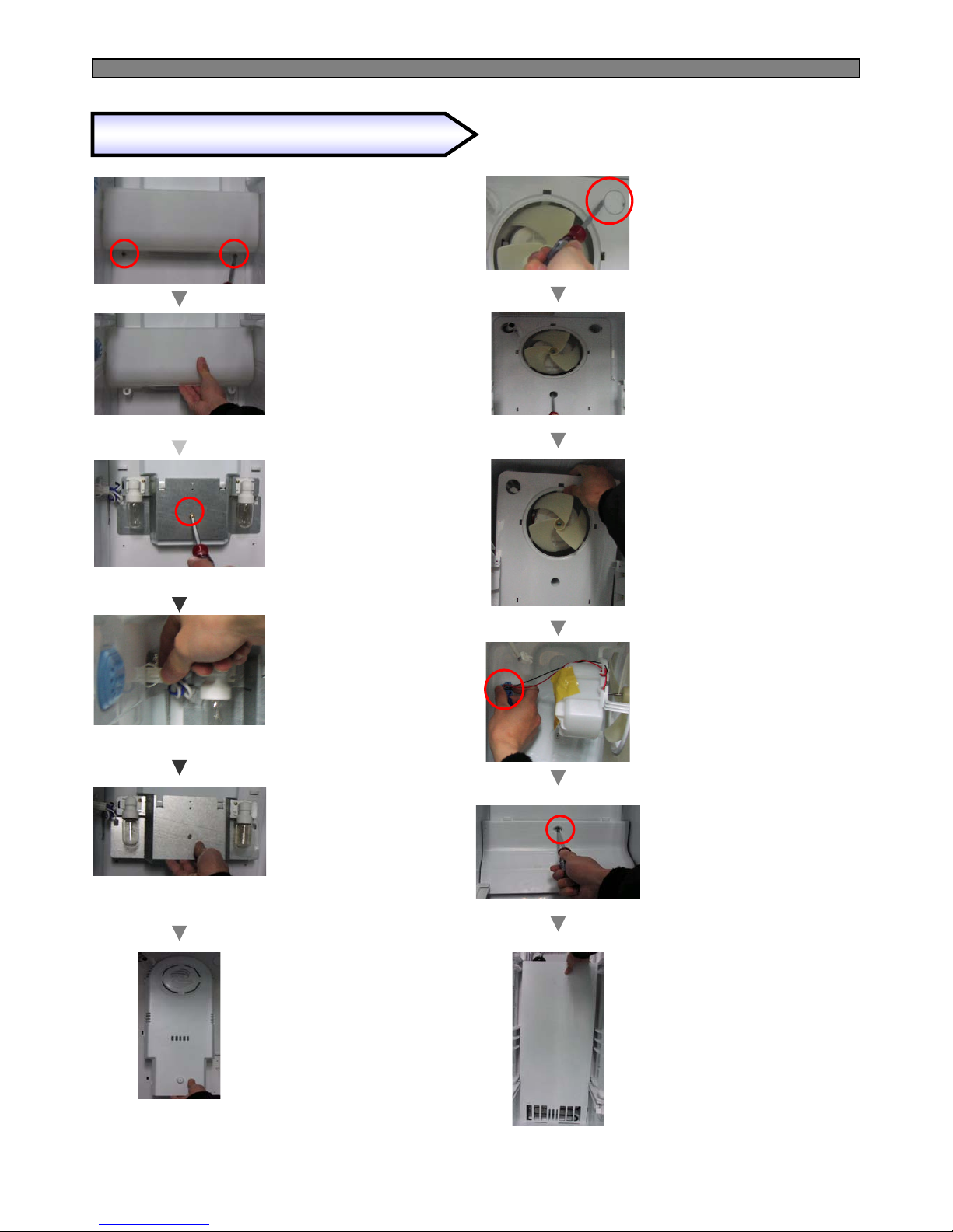
59
* Remove light cover screws.
* Pull down smoothly the
bottom of light cover to
remove.
* Remove the screw of
bracket F-Lamp.
* Remove the left housing.
* Hold the end of F-Fan cover
and pull forward slowly.
* Remove the screw cap on
the F-Louver A with a flat
tip driver.
Removing and replacing Freezer parts
* Pull out smoothly the
bracket F-Lamp AS.
to remove.
* Remove 3 screws of
F-Louver A.
* Hold the end of F-Louver A
and pull forward slowly.
* Remove the housing.
* Remove the screw of
F-Return cover
and pull out cover.
* Hold the end of F-Louver B
and pull forward slowly.
(6)
(7)
(8)
(9)
(10)
(11)
(12)
(13)
(14)
(15)
(16)
(17
Page 61
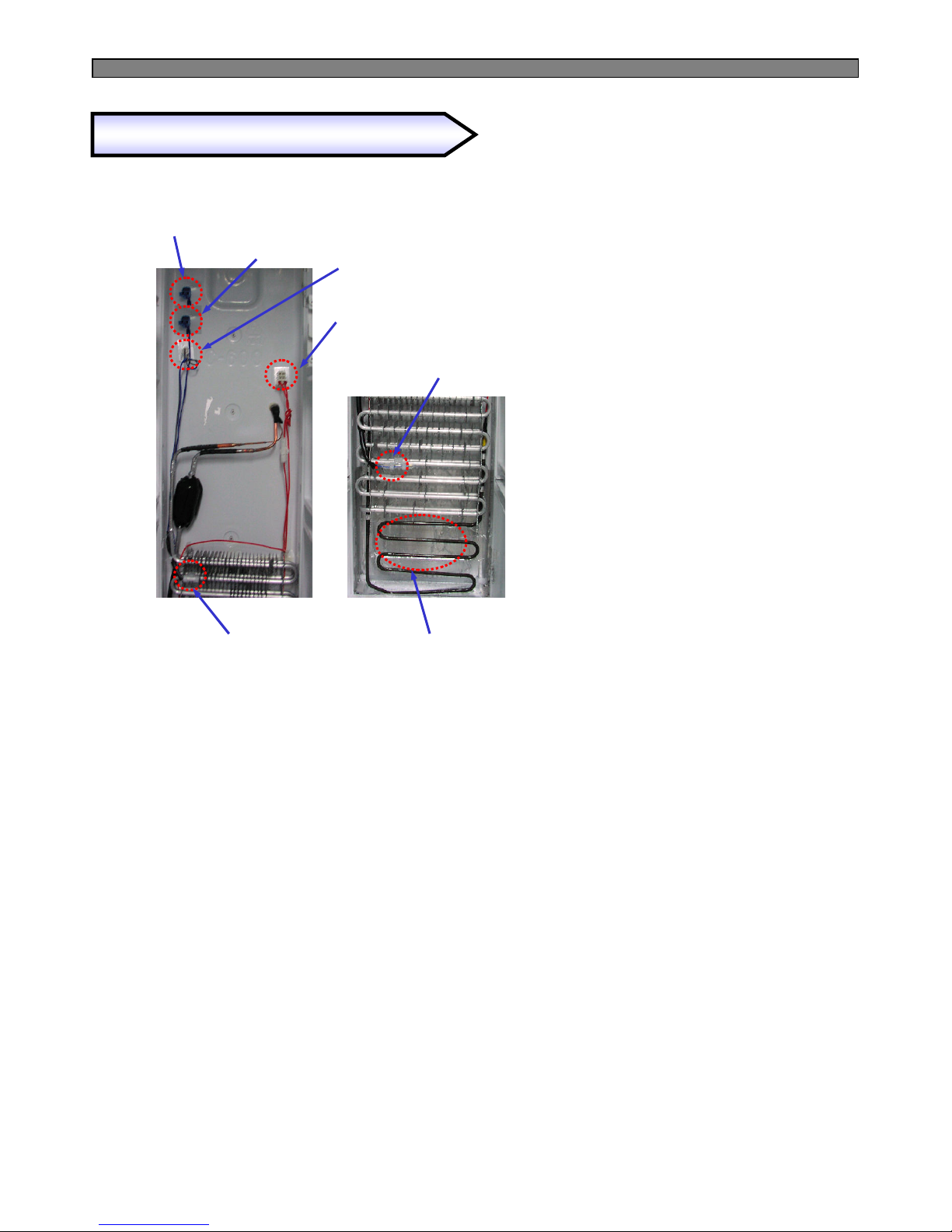
60
Removing and replacing Freezer parts
F-Louver B Heater Housing
D-Sensor Housing
1st : F-Louver B Heater Housing
2nd : None.
3rd : Defrost Heater Housing.
Temp. Fuse
Defrost Heater
D-Sensor Defrost Heater
Temp. Fuse Housing
Page 62
61
Reassemble the door.
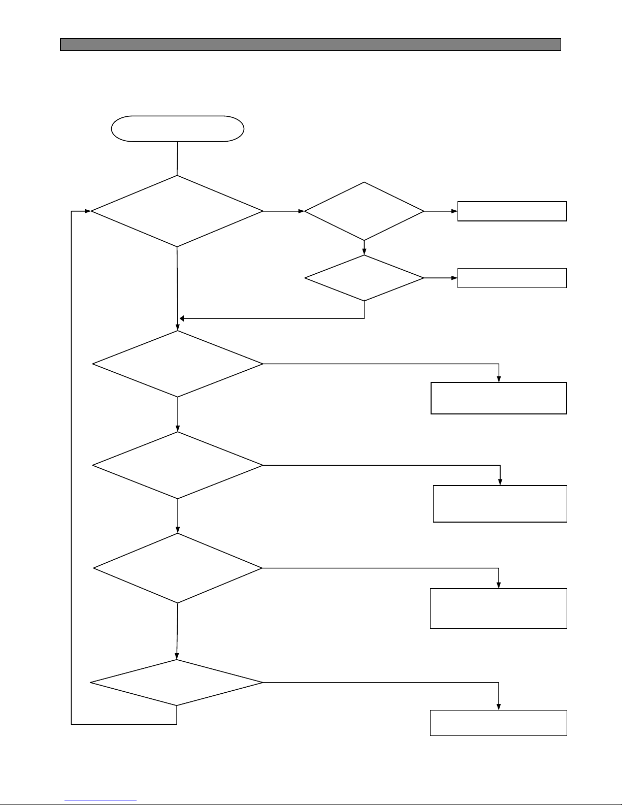
Start
Explain not to open
doors too frequently.
Y
N
N
Y
Remove the gap.
Wipe out dews on the
louver surface and run
the refrigerator again.
Change the louver assembly.
Y
N
Y
Y
Y
N
N
Make enough distance
between heat appliances
and refrigerator.
Y
N
N
9-2-2. Ice Formation on F-Louver
Dews are formed on the
gasket surface inside F
compartment ?
Gasket has a gap
between cabinet ?
Door is hanged
down ?
Door is open and closed
too frequently ?
Heat appliances are too
close to the refrigerator ?
Watery or hot foods are
stored in refrigerator
compartment ?
Louver heater is
disconnected ?
Page 63
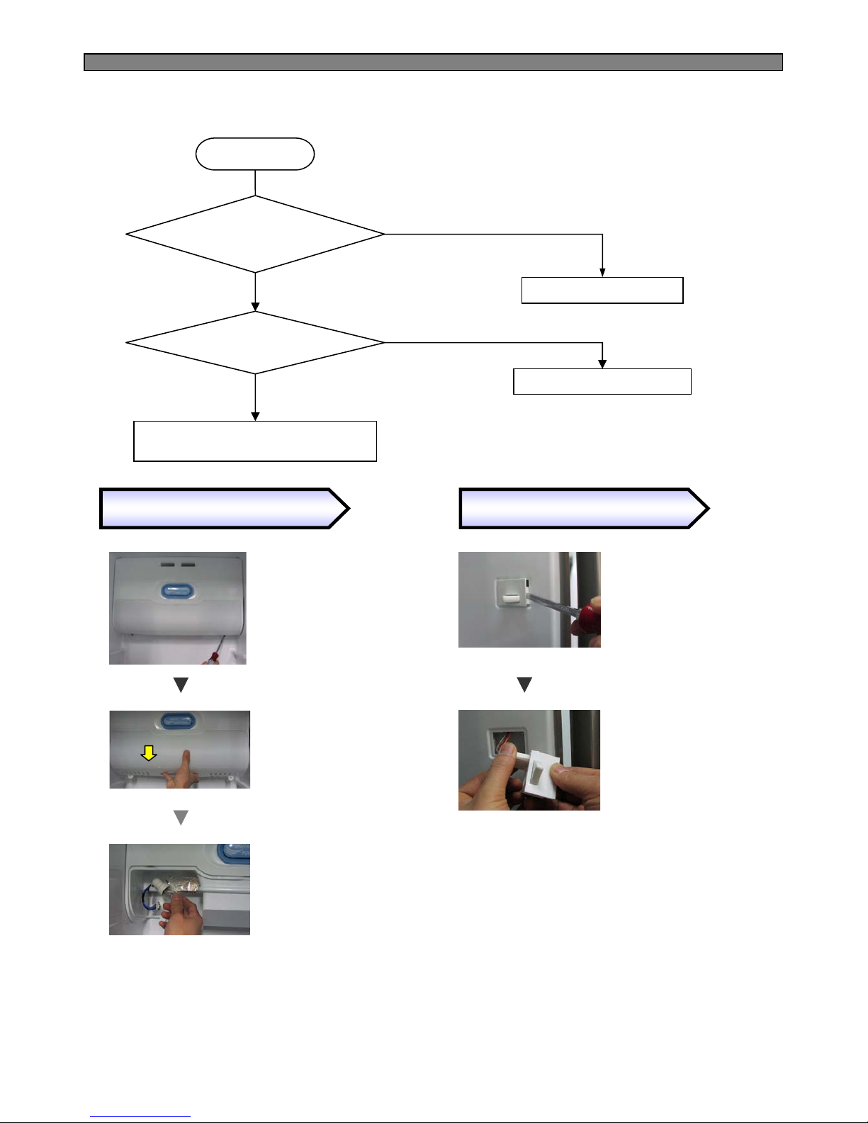
62
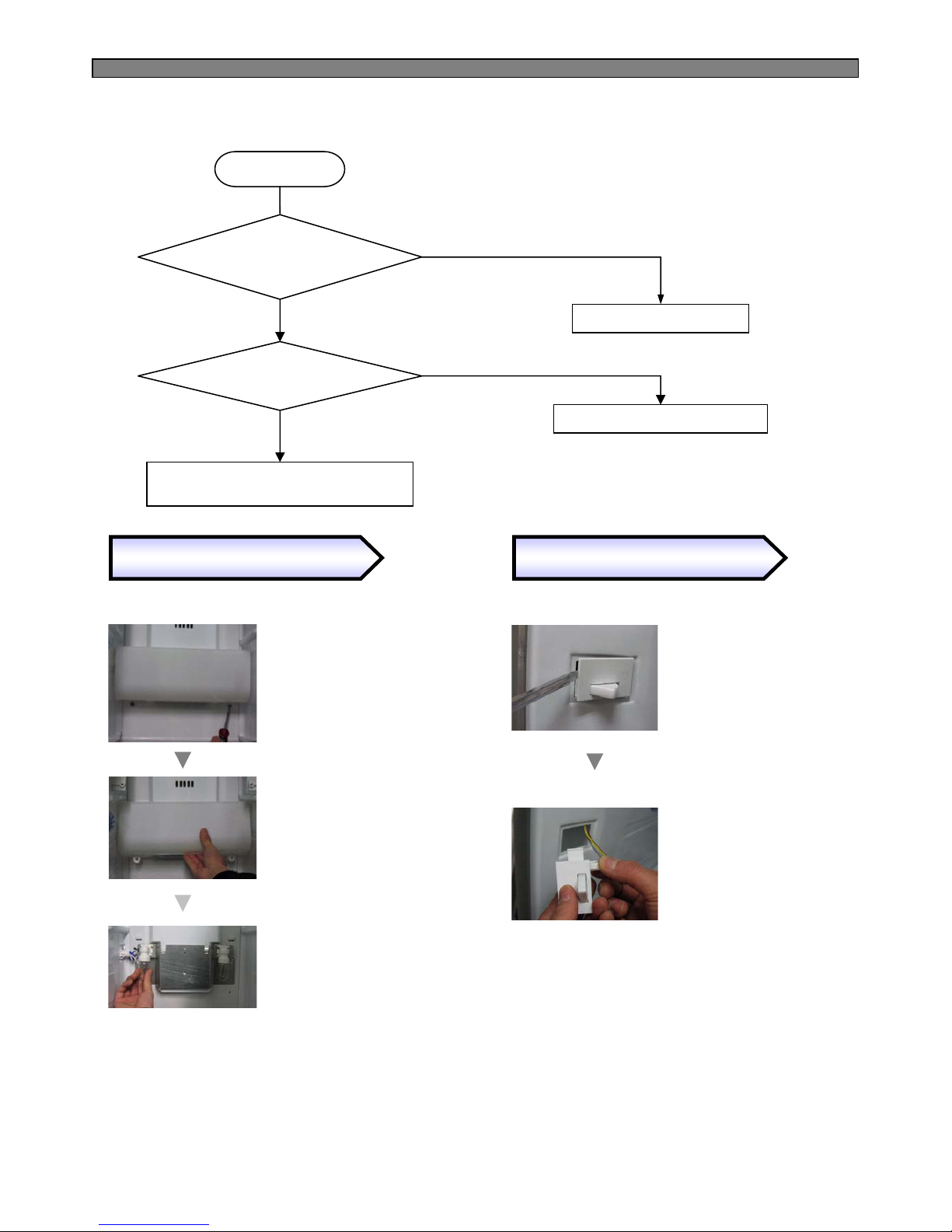
Change the light bulb.
Start
Repair the F-door switch.
Check the F door switch
connection and F-light socket.
Y
N
N
Y
Change of F Lights
Change of F Door Switch
* Remove 2 screws
of light cover.
* Hold the bottom of light
cover and pull forward
to remove.
* Change the light bulb.
(AC240V 25W)
* Insert a flat tip screw
driver Into a gap of door
switch to pull forward.
* Disconnect the housing
and change the switch
for a new one.
①①①①
②②②②
③③③③
①①①①
②②②②
9-2-3. Disconnection / breaking of Freezer Lights Wires
Freezer light filament is
disconnected or breaking ?
Connection of F door
switch is OK ?
※ Be careful when changing
the switch. F and R door
switch are different in type
and shape.
※ Follow the reverse order
of disassembling after
changing the switch.
※ Follow the reverse order
of disassembling after
changing the light.
Page 64
63
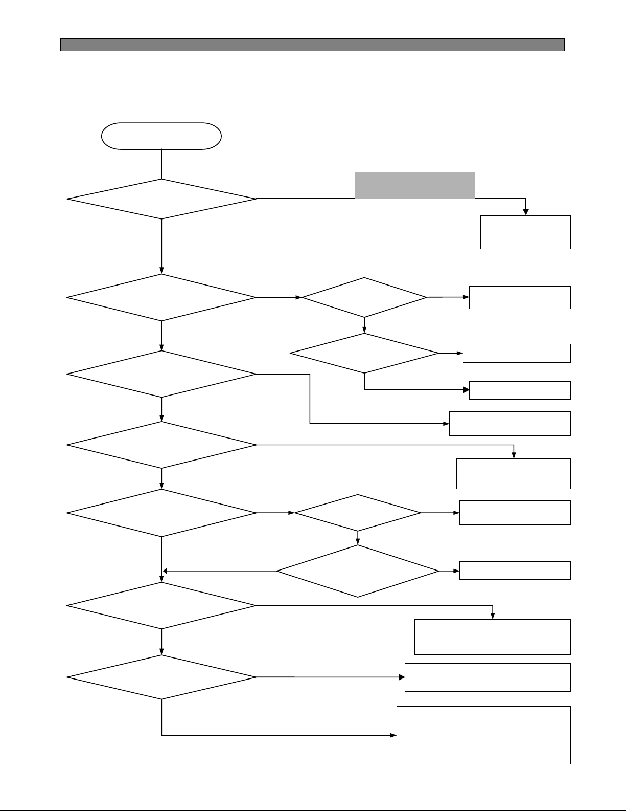
9-3. Refrigerator Compartment
Solve error code
problem, if any.
Start
Y
N
N
Y
N
N
Y
Y
Change
the R-Motor.
Change the Main PCB.
Check the wirings.
Explain not to place foods close to
R-sensor or cold air spout.
Explain not to open doors
unnecessarily or frequently.
N
Y
N
Y
Y
Refer to “Freezing
does not work.”
N
Reassemble doors.
Repair to eliminate
the gap of gasket.
Y
N
Y
N
Change the R-Sensor
and check connector.
Y
Y
N
N
9-3-1. Refrigeration failure (Foods does not get cool or cold soon.)
Any error mode
on F-PCB?
R-Motor works OK ? R-Motor is OK ?
Wiring connection
Is OK ?
R-Sensor is OK
(normal) ?
Freezer compartment
Is OK ?
Refrigerator gasket
have gap ?
Gasket have
any gap ?
Door is hanged down
to make gap between
cabinet ?
Foods are placed just
close to R-Sensor ?
Refrigerator door
openings are too often ?
* Advise to use in “HIGH” mode
* Jumper cutting of Main PCB to
prevent weak refrigeration ;
→ Option 1 : cut J18 to down 1.5℃.
→ Option 2 : cut J19 to down 1.5℃.
※※※※ Refer to the 4-10.
(Error Display)
Page 65
64
* Remove screws
of light cover.
* Hold the bottom
of cover and pull
forward to remove.
①①①①
②②②②
③③③③
* Change the light
bulbs.
(AC240V 25W)
Change the light bulb.
Start
Repair the R-door switch.
Check the R-door switch
connection and R-light socket.
Y
N
N
Y
Freezer light filament is
disconnected or breaking ?
Connection of R door
switch is OK ?
9-3-2. Disconnection / Breaking of Refrigerator Lights Wires
Change of F Lights
Change of F Door Switch
※ Follow the reverse order
of disassembling after
changing the light.
①①①①
②②②②
* Insert a flat tip screw
driver into a gap of door
switch to pull forward.
* Disconnect the housing
and change the switch
for a new one.
※ Be careful when changing
the switch. F and R door
switch are different in type
and shape.
※ Follow the reverse order
of disassembling after
changing the switch.
Page 66
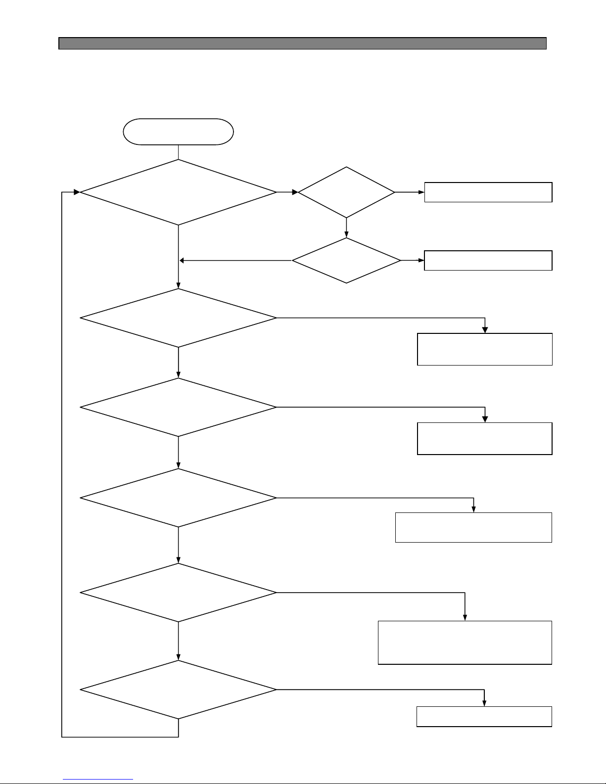
65
Reassemble the doors.
Start
Explain not to open
doors unnecessarily.
Y
Y
Repair to eliminate the gap.
Make enough distance between
the appliances and refrigerator.
Advise to cool down foods, wrap
or cover foods with much water
before storing in the compartment.
Repair and change R-motor.
Y
N
Y
Y
Y
N
N
N
N
Explain not to open doors
too long.
Y
N
N
N
Y
9-3-3. Dews on Refrigerator Compartment
Dews are formed
on the gasket inside
R-compartment?
Gasket has
Any gap ?
Door is
hanged down ?
Door is open too long ?
Door is open and closed
too frequently ?
Heat appliances are
used near the refrigerator ?
Watery or hot foods are
stored in the R-compartment?
R-fan works OK ?
Page 67
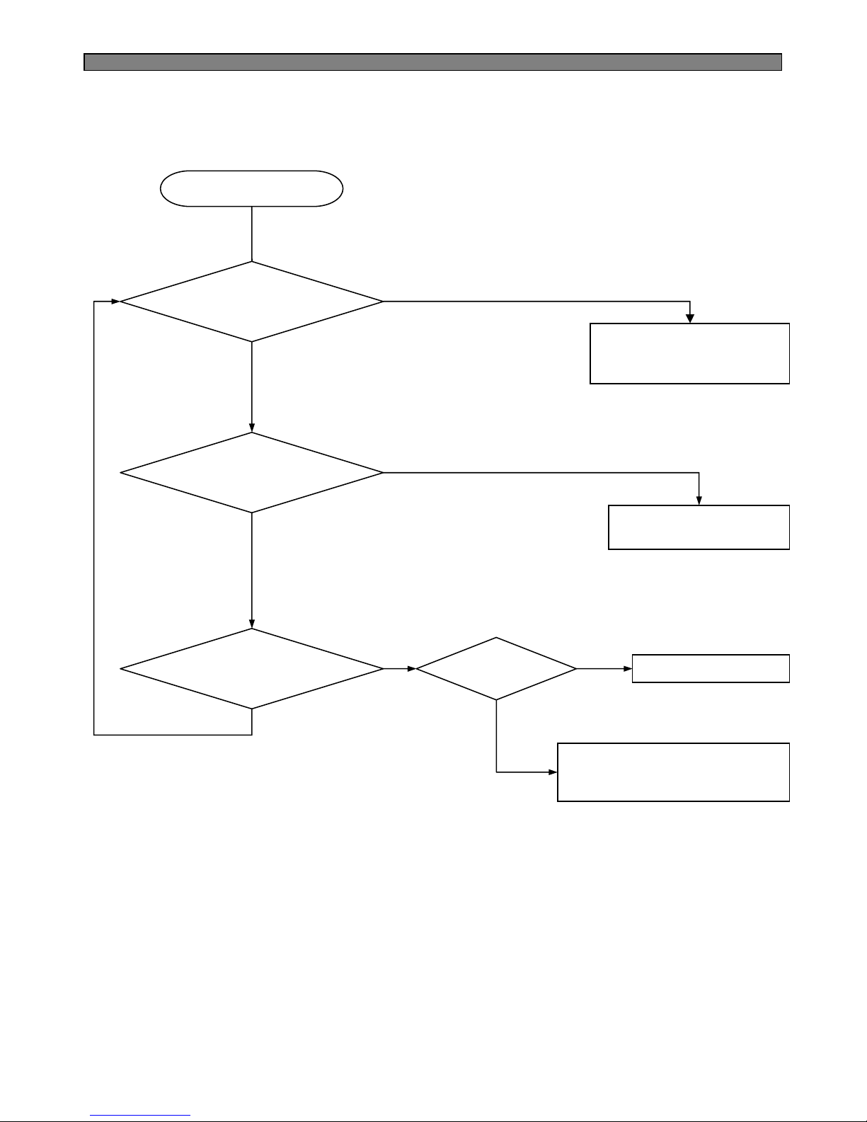
66
Start
Explain the temperature modes.
Advise to set the temp. to
“Middle” or “LOW” mode.
N
Repair and/or Change
the R-check valve.
Change the R-sensor.
Y
N
N
Y
Check the R-sensor connection.
(Check the connector to Main PCB.)
N
Y
※ Refer to “Repair /Change
of Check Valve”.
Y
9-3-4. Excessive Refrigeration of Vegetable Case
Refrigerator temp.
mode is “HIGH” ?
R-check valve
Works OK ?
Is there any
R-sensor error code ?
R-sensor is OK ?
Page 68
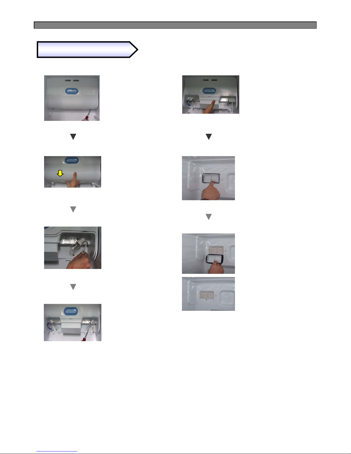
67
* Hold the bottom and
right of damper to pull
down to remove.
* Lift up a piece of Check Valve
Flap and insert a finger to the
valve frame to hold out.
⑤⑤⑤⑤
⑦⑦⑦⑦
⑥⑥⑥⑥
⑧⑧⑧⑧
Removing of Check Valve
* Remove screws
of light cover.
* Hold the bottom
of cover and pull
forward to remove.
①①①①
②②②②
③③③③
④④④④
* Disconnect light
housing.
* Remove screws with a
(+)screw driver.
Page 69
68
Start
Level the refrigerator by
adjusting wheels.
☞ Refer to User’s Guide
and SVC Manual.
Y
N
Set it right.
Y
N
Change the Rubber absorber.
Y
N
Attach a restrainer on the comp.
head to reduce vibration and
high frequency noise.
Y
N
Change the compressor.
Remarks
● Compressor sound is somewhat normal because it works like a heart to circulate the refrigerant in
the pipes during the refrigerator operation.
● Rattling or metallic touch sound of motor, piston of comp. can be heard when it starts or stops.
9-4. Operation Noise of Refrigerator
9-4-1. Comp. operation Noise
Refrigerator is leveled ?
Front cover or door gasket
is assembled wrong ?
Rubber absorber comp
is distorted or aged ?
Sound from Comp itself
or Vibration ?
Page 70
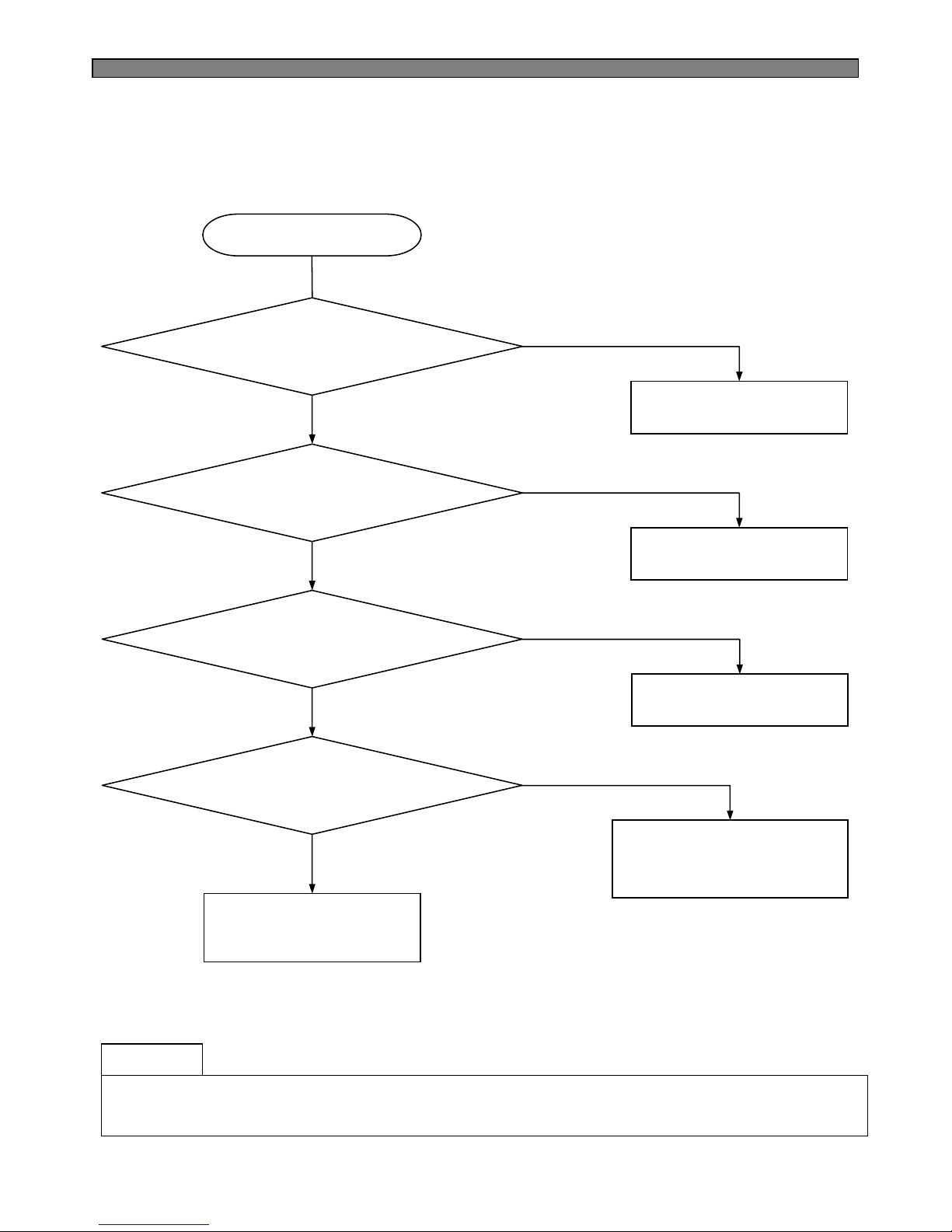
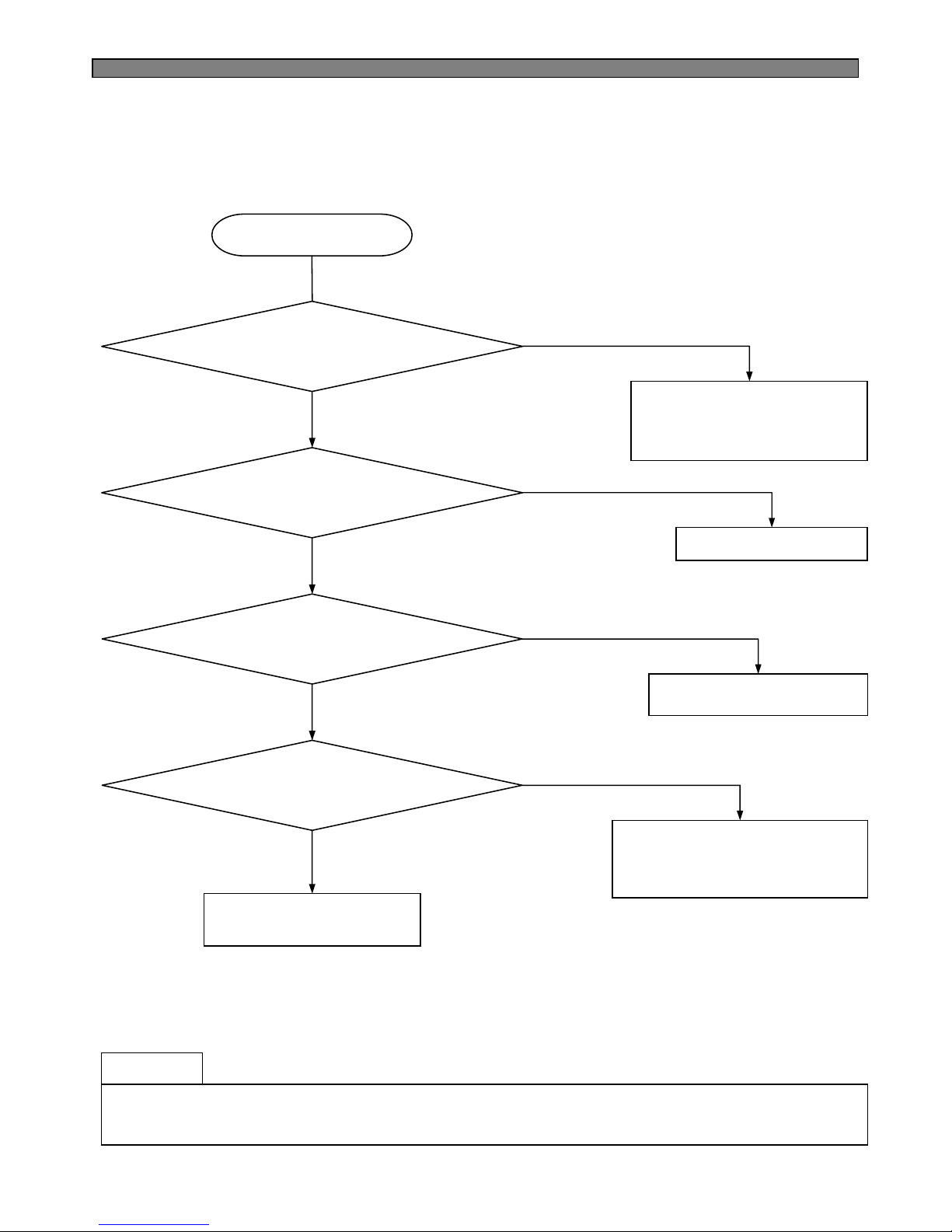
69
Start
Attach an absorber gum
on the capillary tube.
N
Y
Apply a gum on the
accumulator.
Y
N
Apply a gum on the
accumulator.
Y
N
Fasten the evaporator in F-
compartment tightly against
touching (liner) surfaces.
N
Y
Explain refrigerator work
mechanism and sound to the
users or customers.
Remarks
● Water flowing sound, hiss or sizzling sound can make while refrigerant in the pipes is changing from
liquid to gas state when comp. starts or stops.
It is normal to the refrigerator.
9-4-2. Refrigerant Flow Sound
Water flowing or hiss sounds
from the refrigerator ?
Refrigerant sound of hiss or
sizzling sound when comp. starts ?
Refrigerant sound of hiss or
sizzling when comp. stops ?
Any shaking sound from
F-compartment
when comp. works ?
Page 71
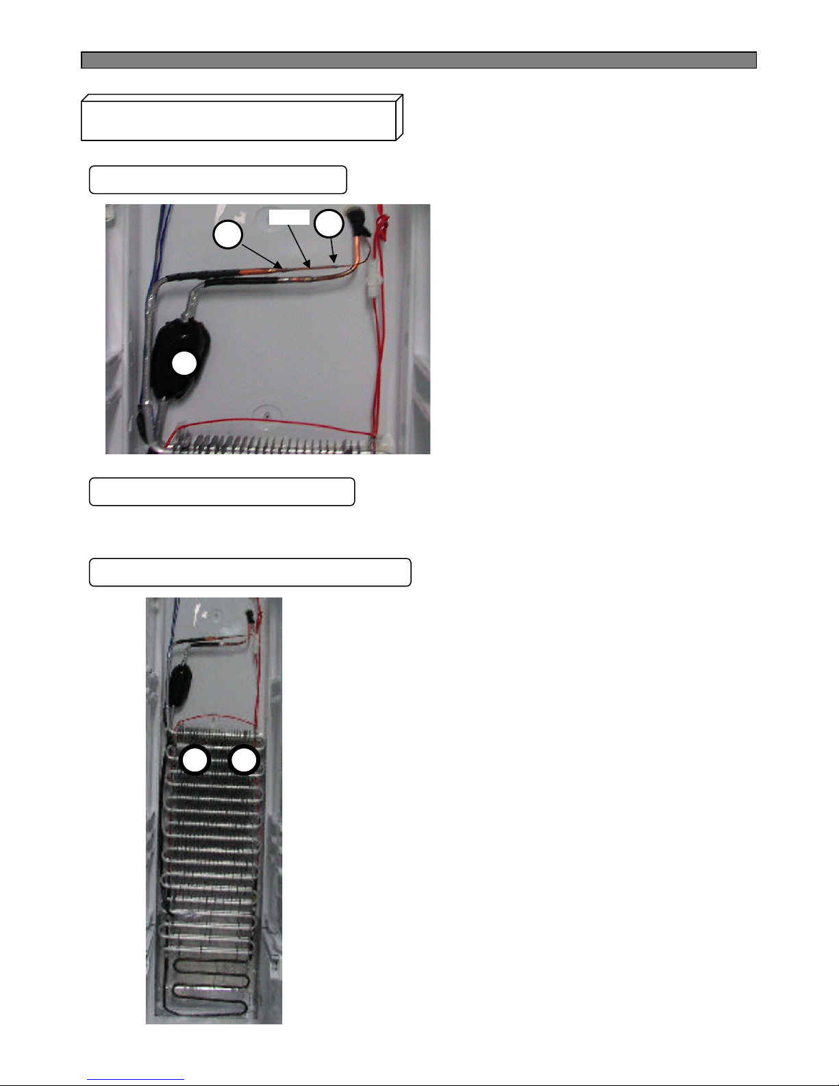
70
Troubleshooting of Evaporator Sound
1. Hiss Sound from Capillary Tube
1) “I” tube is used to connect the
capillary tube and evaporator.
(2 welding points : ①, ②)
2. Sizzling Sound from Accumulator
3. Shaking or trembling Sound of Evaporator
1
2
2) When such a sound is made,
attach a absorber on the tube
including 2 welding points.
Attach a absorber on point ③ (accumulator).
1) Check whether evaporator is fastened tight
with the fasteners of ①, ②.
2) Insert a soft spacer (EPS) between left and right wall.
Evaporator not to be shaken or trembled during
refrigerator operation.
1
3
“I” tube
2
Page 72
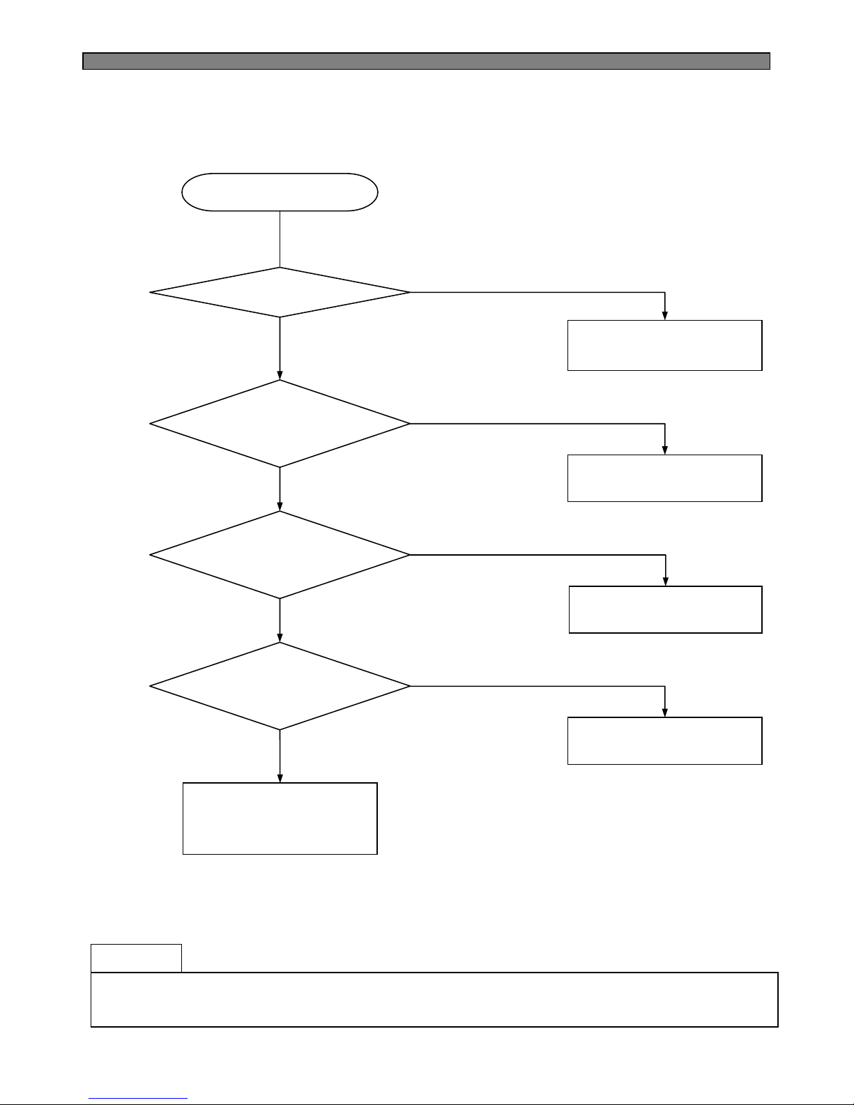
71
Remarks
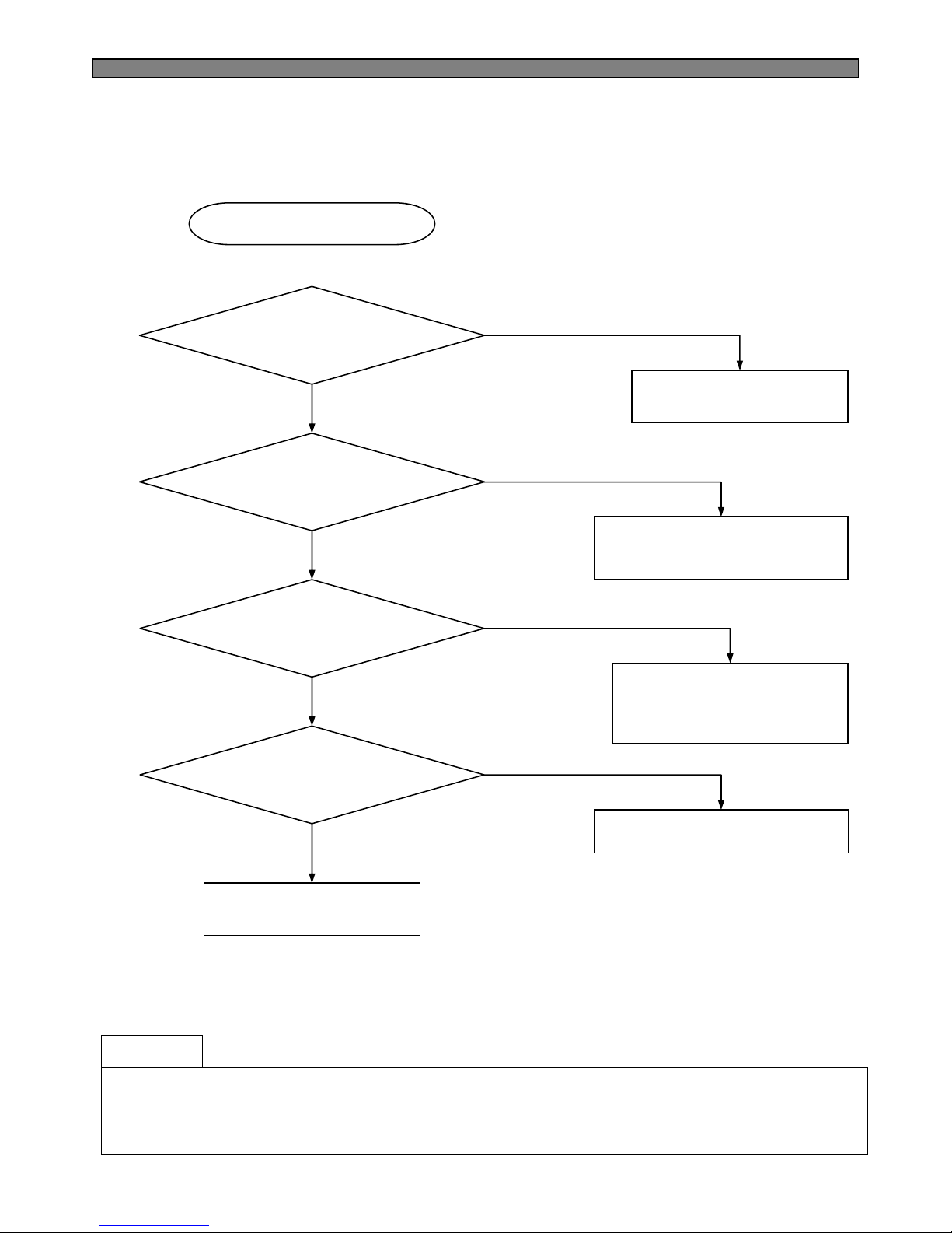
● The fan is sending out cold air to circulate it through the compartments.
When the air is touching the surface of louver or liner wall, such sound can make.
Start
Change the fan.
N
Y
Set it right not to touch.
Y
N
Set it right not to move.
Y
N
Change the motor
assembly.
N
Y
Explain to the customers
how fan is working to
circulate cold air in the
compartments.
9-4-3. Fan Noise
Fan is damaged
or transformed ?
Fan is touching
the surround ?
Fan-motor assembly
is moving or shaking ?
Motor has its own noise
or vibration when working ?
Page 73
72
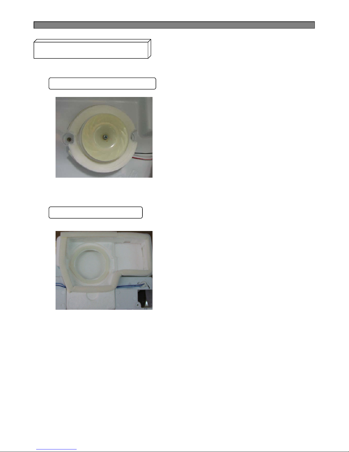
2) Check if fan motor and fan are hanged down.
Fan working sound can be louder if they are
not set right.
2. Any Touch Sound from Fan
Troubleshooting of Fan Noise
1. Fixing or Fastening of Fan Motor
1) Check if fan motor frame of the assembly is
fastened tightly with screws to the liner wall.
Unless it is tight, vibration of shaking can make.
1) Check if sealing sponge on the insulator
touches the fan.
If so, set it again not to touch it.
2) If any damage on the insulator around the fan
rotation is found, set the fan motor assembly right
not to touch it.
Page 74
73
Remarks
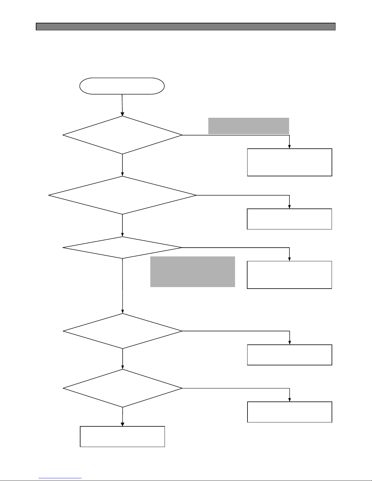
● Refrigerant is erupting rapidly from the compressor to circulate pipes, so pipe shaking noise
can make to some degree.
● In case compressor vibration is sent to a pipe directly, apply vibration absorber rubbers to welding
points of the pipe and comp. or to a much bent point on the pipe.
Start
Separate the touching
pipes, if any.
N
Y
Apply cushion material between
Comp. base and Tray drip.
Y
N
Move or change the points of
vibration absorber rubbers on
the pipes to reduce the shaking.
Y
N
Attach a absorber
on the comp. head.
N
Y
Explanation to the users.
9-4-4. Pipe Noise
Pipes are touching
in the machine compartment ?
Tray drip makes
noise by Condenser shaking ?
Pipe itself is
shaking much ?
Compressor itself
is shaking much ?
Page 75
74
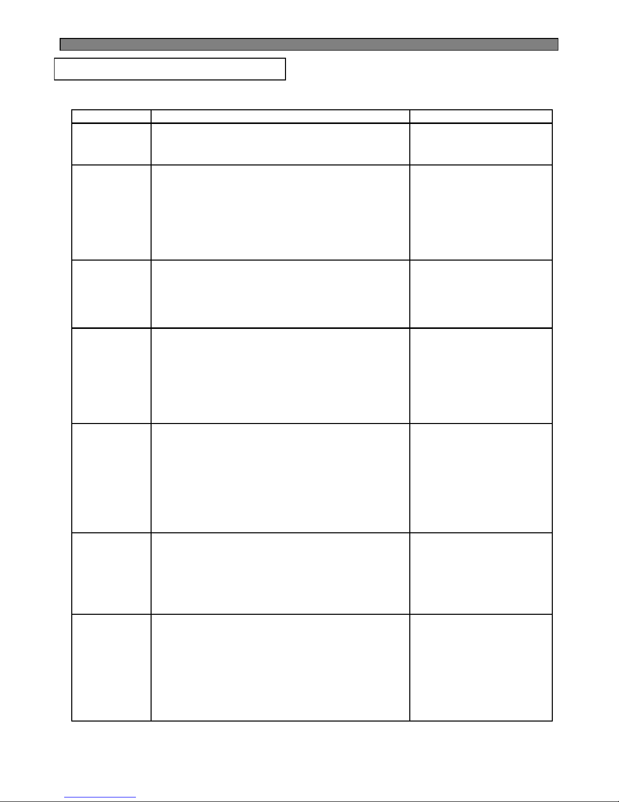
Door switch is soaked with
water or there is water in
the switch ?
PCB input is OK ?
Start
Change the door switch.
N
Y
Repair any disconnection
of wires and defective
Door switch.
Y
Connector insertion to
Main PCB is OK ?
N
Repair the defective
connection.
Y
Door switch itself is
OK ?
N
Change the switch.
N
Y
Check it up.
Door switch is pushed
well ?
Y
Attach a thin pad on the
door liner or change the
door assembly.
Check if interior light is ON.
N
9-5. Door
9-5-1. Door Opening Alarm Continues though the door is closed.
Check #5,6 of CN8 (F-Door)
and #4,6 of CN7 (F-Door).
→ Open : 5V, Close : 0V
Page 76
75
10-1. Summary of Heavy Repair
* Installation should be conducted in accordance with
the standard installation procedure. (Leave space of
more than 5 cm from the wall for compressor
compartment cooling fan mounted model.)
Transportation
and
installation
* Copper brush, Rag, Tool box
* Remove flux from the silver weld joints with soft
brusher wet rag. (Flux may be the cause of corrosion
and leaks.)
*Clean tools and store them in a clean tool box
or in their place.
Compressor
compartment
and tools
arrangement
* Electronic Leak Detector,
Driver.
* Check leak at weld joints.
Note :Do not use soapy water for check.
* Check cooling capacity
→
Check condenser manually to see if warm.
→
Check hot pipe manually to see if warm.
→
Check frost formation on the whole surface of the
evaporator.
Check
refrigerant leak
and cooling
capacity
* Bombe (mass cylinder),
refrigerant manifold gauge,
electronic scales, punching
off flier, gas welding machine
* Weigh and control the bombe in a vacuum conditions
with electronic scales and charge through compressor
inlet (Process tube).
* Charge while refrigerator operates).
* Weld carefully after inlet pinching.
Refrigerant
charging and
charging
inlet welding
* Vacuum pump
, Manifold gauge.
* Evacuate for more than forty minutes after connecting
manifold gauge hose and vacuum pump to high (drier)
and low (compressor) pressure sides.
Vacuum
* Pipe Cutter, Gas welder,
N2 gas
* Confirm refrigerant (R-134a or R-600a) and oil for
compressor and drier.
* Confirm N2 sealing and packing conditions before use.
Use good one for welding and assembly.
* Weld under nitrogen gas atmosphere.
* Repair in a clean and dry place.
Parts
replacement
and welding
* Nipper, side cutters
* Cut charging pipe ends (Comp. & Dryer) and
discharge refrigerant from drier and compressor.
Remove
refrigerant
Residuals
ToolsContentsProcess
10. COOLING CYCLE HEAVY REPAIR
Page 77
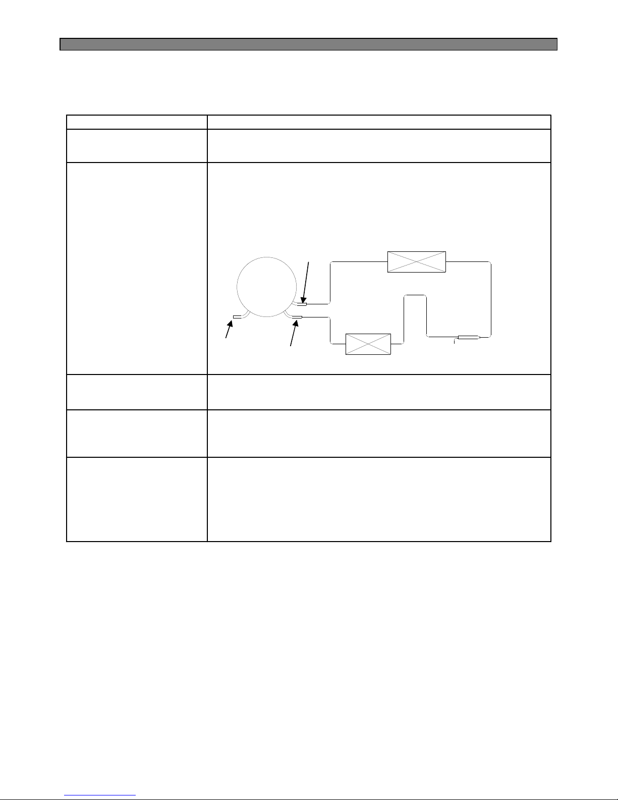
76
1) Nitrogen only should be used when cleaning inside of cycle pipes
inside and sealing.
2) Check leakage with an electronic leakage tester.
3) Be sure to use a pipe cutter when cutting pipes.
4) Be careful not the water let intrude into the inside of the cycle.
Others.
1) Weld under nitrogen atmosphere in order to prevent oxidation
inside a pipe. (Nitrogen pressure : 0.1~0.2 kg/cm2.)
Nitrogen blowing
welding.
1) Be sure to replace drier when repairing pipes
and injecting refrigerant.
Replacement of drier.
1) Remove retained refrigerant more than 5 minutes after turning off
a refrigerator. (If not, oil will leak inside.)
2) Remove retained refrigerant by cutting first high pressure side
(drier part) with a nipper and then cut low pressure side.
(If the order is not observed, oil leak will happen.)
Removal of retained
refrigerant.
1) Use special parts and tools for R-134a or R-600aUse of tools.
PrecautionsItems
10-2. Precautions During Heavy Repair
Process tube
Compressor
Evaporator
Dryer
High Pressure side
Low pressure
side
Suction tube
Discharge tube
Condenser
Hot Pipe
Page 78
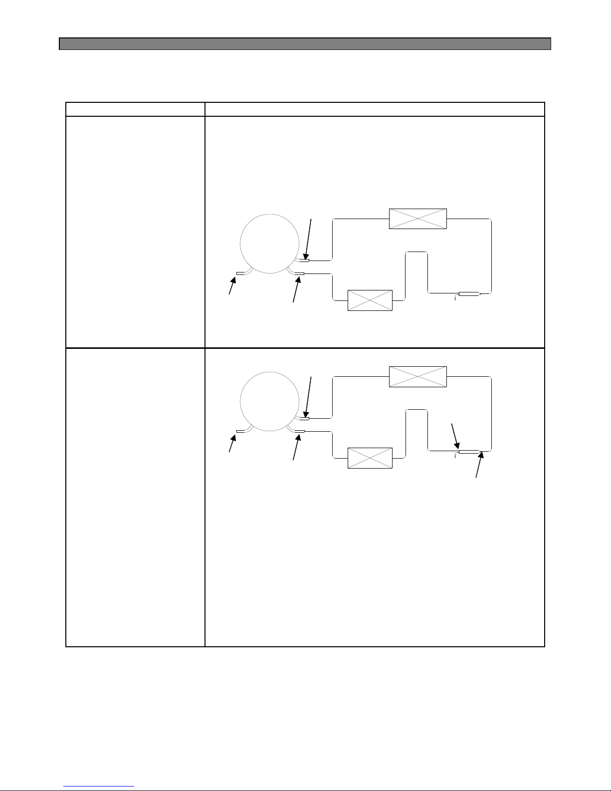
77
1) Remove residual refrigerant more than 5 minutes later after
turning off the refrigerator. ( If not, compressor oil may leak inside.)
2) Remove retained refrigerant slowly by cutting first high pressure
side (drier part) with a nipper and then cut low pressure side.
1. Removal of residual
refrigerant.
PrecautionsItems
10-3. Practical Work for Heavy Repair
* When replacing a drier:
Weld ①and② parts by blowing nitrogen (0.1~0.2kg/cm2) to high
pressure side after assembling a drier.
* When replacing a compressor:
Weld ③and④ parts by blowing nitrogen to the low pressure side.
Note) For other parts, nitrogen blowing is not necessary because it
does not produce oxidized scales inside pipe because of its short
welding time.
2. Nitrogen blowing
welding.
※※※※ KEYPOINTING
Welding without nitrogen blowing produces oxidized scales inside
a pipe, Which affect on performance and reliability of a product.
Process tube
Compressor
Evaporator
Dryer
High Pressure side
Low pressure
side
Suction tube
Discharge tube
Condenser
Hot Pipe
Process tube
Compressor
Evaporator
Dryer
High Pressure side
Low pressure
side
①
Condenser
②
③
④
Hot Pipe
Page 79
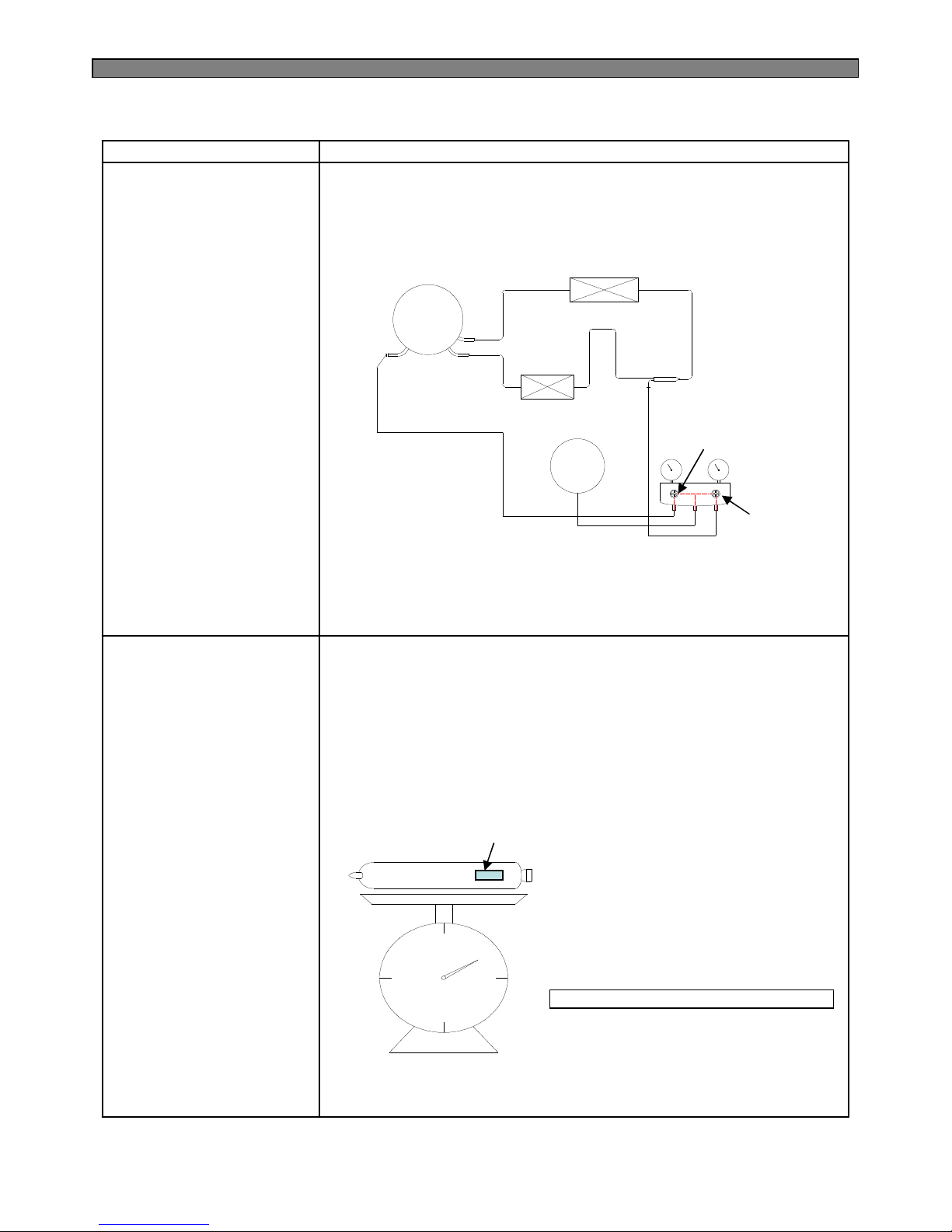
78
* Pipe Connection
Connect a red hose to the high pressure side and a blue hose
to the low pressure side.
* Vacuum Sequence
Open ①,② valves and evacuate for 40 minutes.
Close valve ①.
3.Vacuum degassing.
PrecautionsItems
* Charging sequence
1) Check the amount of refrigerant supplied to each model after
completing vacuum degassing.
2) Evacuate bombe with a vacuum pump.
3) Measure the amount of refrigerant charged.
- Measure the weight of an evacuated bombe with an electronic scale.
- Charge refrigerant into a bombe and measure the weight. Calculate
the weight of refrigerant charged into the bombe by subtracting the
weight of an evacuated bombe.
4.Refrigerant charging.
Compressor
Evaporator
DryerCondenser
Vaccum
Pump
Hot Pipe
Blue
Yellow
Red
High
Pressure
Low
Pressure
①
②
※※※※ KEYPOINTING
1) If power is applied during vacuum degassing, vacuum degassing
shall be more effective.
2) Operate compressor while charging refrigerant. (It is easier and
more certain to do like this.)
the amount of refrigerant charged
= a weight after charging
- a weight before charging
(a weight of an evacuated cylinder)
Calculation of amount of refrigerant charged
※※※※ KEYPOINTING
1) Be sure to charge
the refrigerant at
around 25°C.
2) Be sure to keep
-5g in the winter
and +5g in summer.
Indicate the weight of
an evacuated bombe
Page 80
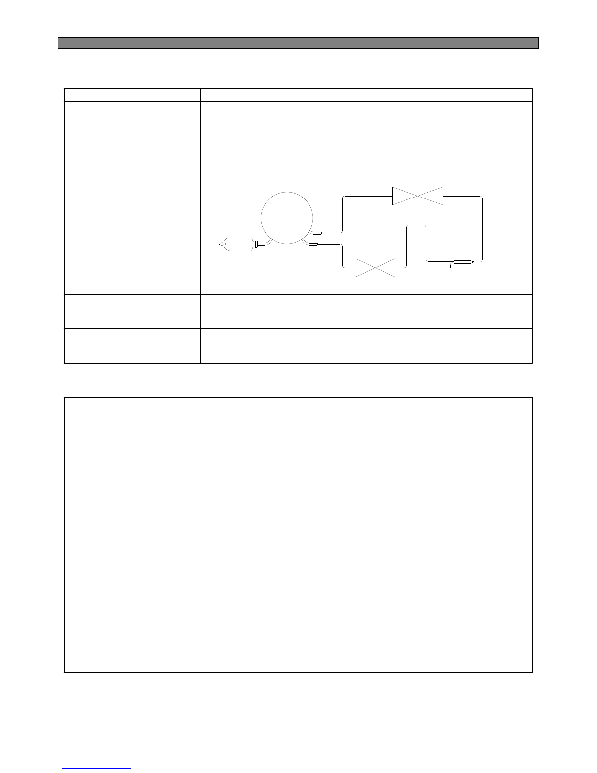
79
PrecautionsItems
4) Refrigerant Charging
Charge refrigerant while operating a compressor as shown above.
5) Pinch a charging pipe with a pinch-off plier after completion of charging.
6) Braze the end of a pinched charging pipe with copper brazer and take
a gas leakage test on the welded parts.
4.Refrigerant charging.
Bombe
Compressor
Evaporator
Condenser
Dryer
Hot Pipe
* Take a leakage test on the welded or suspicious area with an
electronic leakage tester.
5. Gas-leakage test
* Check each pipe is placed in its original place before closing
a cover back-M/C after completion of work.
6. Pipe arrangement
in each cycle
10-4. Standard Regulations for Heavy Repair
1) Observe the safety precautions for gas handling.
2) Use JIG (or wet towel) in order to prevent electric wires from burning during welding.
(In order to prevent insulation break and accident.)
3) The inner case shall be melted and insulation material (polyurethane) shall be burnt
if not cared during welding inner case parts.
4) The copper pipe shall be oxidized by overheating if not cared during welding.
5) Not allow the aluminum pipes to contact to copper pipes. (In order to prevent corrosion.)
6) Make sure that the inner diameter should not be distorted while cutting a capillary tube.
7) Be sure that a suction pipe and a filling tube should not be substituted each other during welding.
( High efficiency pump.)
Page 81
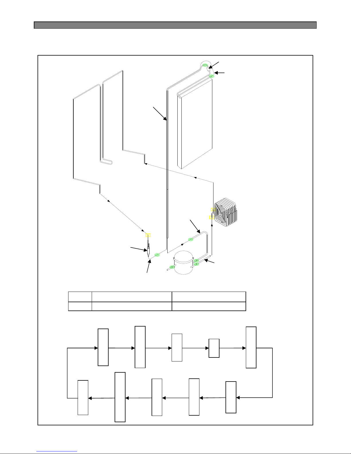
80
10-5. Brazing Reference Drawings.
▶ Welding Point
●
■
Copper Welding (Ag 5%)
7 Points
3 Points
Silver Welding (Ag 35%)
Hot Pipe
F
R
Evaporator
Condenser
I-Pipe
Accumulator
Suction Pipe
Dryer
Capi-Tube
Pipe Suc Conn
Pipe Conn B
Compressor
▶ Flow of Refrigeration Cycle
Compressor
Pipe Conn. B
Wire-Con. Pipe
Hot Pipe
Dryer
Capillary Tube
Evaporator
Accumulator
Pipe Suction Conn
Suction Pipe
High Low
Page 82
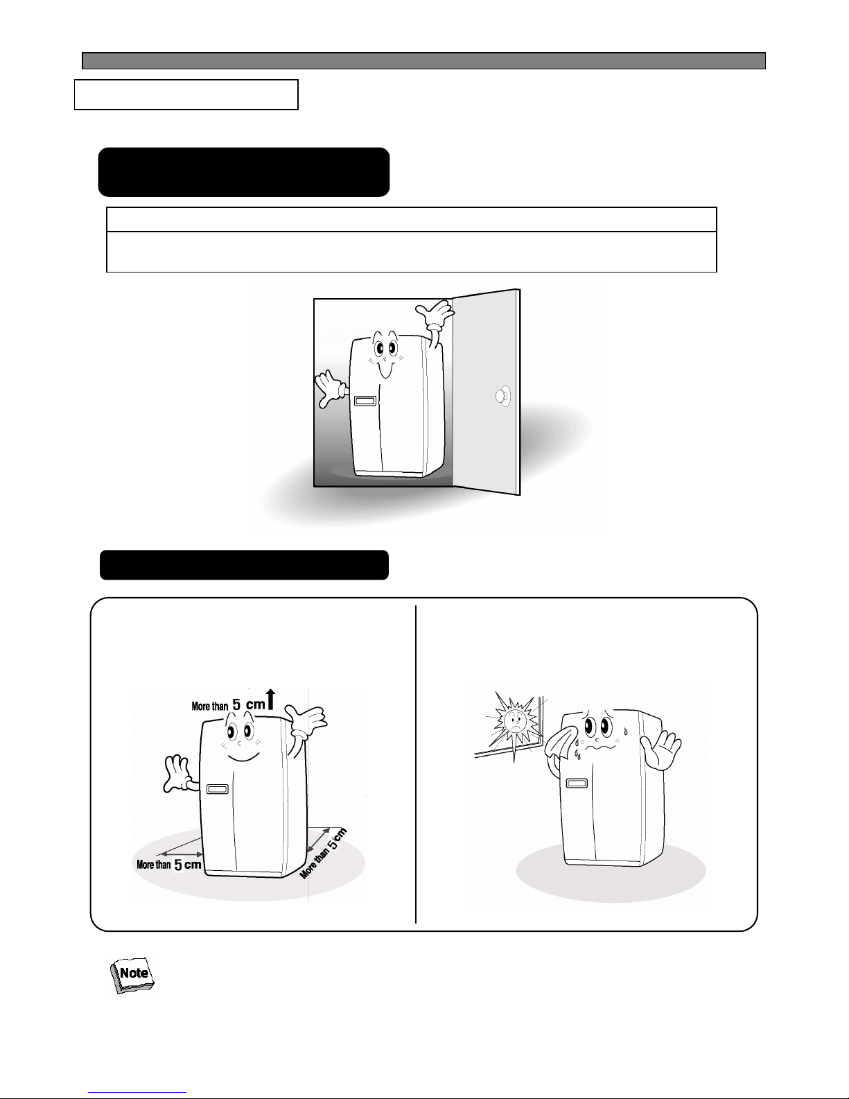
81
11-1. Installation Preparation
11. INSTALLATION GUIDE
Check if the refrigerator can pass
a doorway or enter a door first.
Dimensions( including Door Handles)
(Width*Depth*Height)
903mm X 734.5mm X 1790mm
Find a suitable place to install
Sufficient space from refrigerator back to the
※wall for free air ventilation
※Avoid direct sunlight.
Once the installation place is ready follow the installation instructions.
If surround temperature of refrigerator is low (below 10℃)),
foods can be frozen or the refrigerator can work in abnormal way.
Page 83
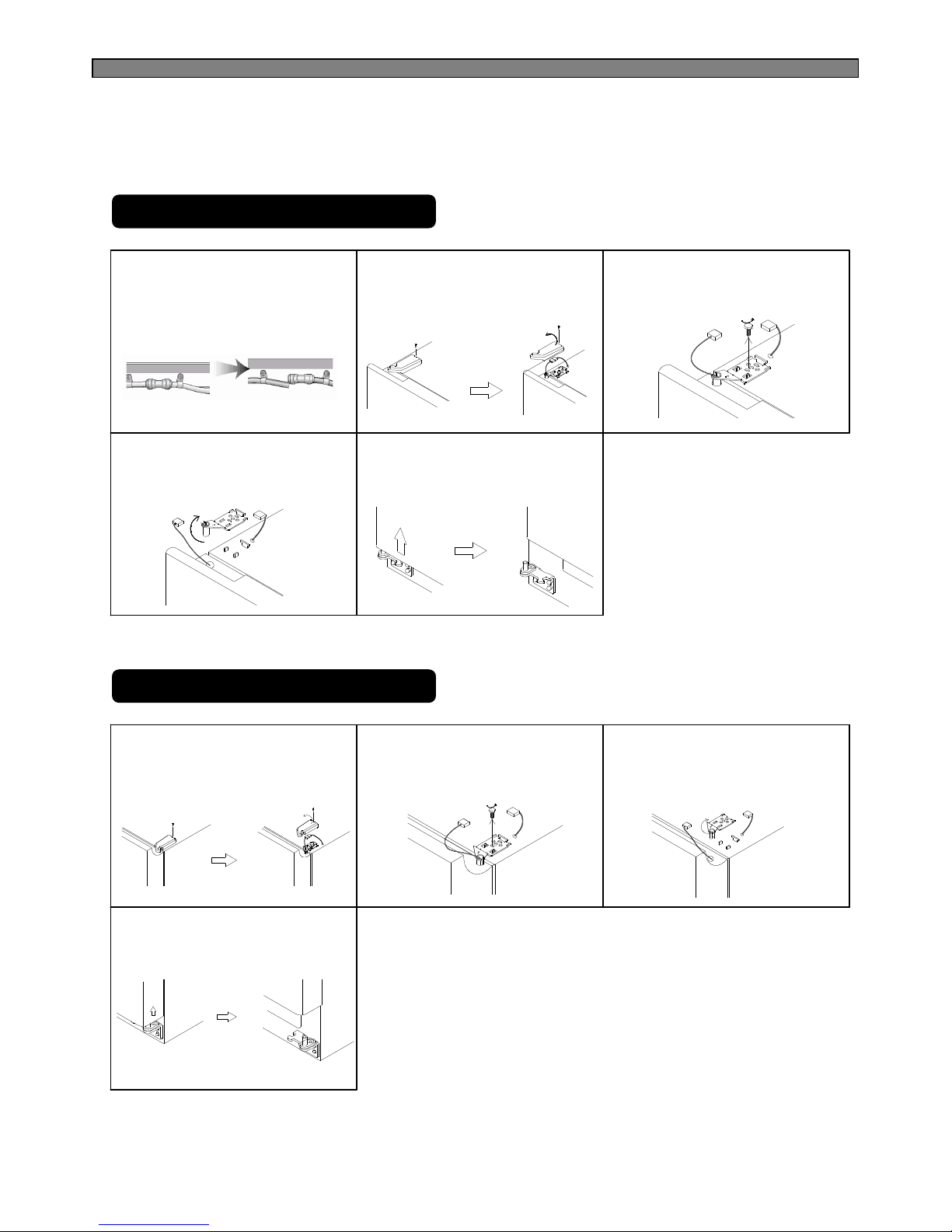
82
11-2. If the refrigerator can not enter the door
Removing Freezer Door
1
※Remove front bottom cover first, if it is attached.
Remove front bottom cover first,
Pull out the left collar of the
coupling first, then hold the
coupling and pull out the left
water tube.
2
Unscrew top hinge cover with a
screw driver.
Remove the hinge cover.
3
Turn top hinge bolt
counterclockwise .
Disconnect the harness wires.
4
Lift up the front of hinge to remove.
( After the hinge is removed the
door can fall down forward.
Be careful !)
5
Be careful not to damage the
water line when removing the
door.
Removing Refrigerator Door
1
Unscrew top hinge cover with a
screw driver.
Remove the hinge cover.
2
Turn top hinge fastener
counterclockwise.
Disconnect harness wires.
3
Lift up the front of hinge to remove.
(After the hinge is removed the
door can fall down forward.
Be careful !)
4
Lift the door straight up to remove.
Page 84
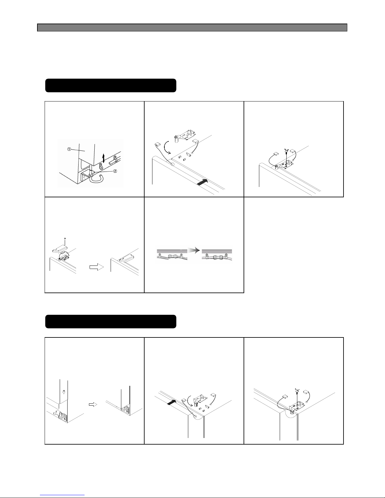
83
Replacing Freezer Door
1
Insert the water tube into the hole
Of the bottom hinge pin first, then
Insert the bottom of freezer door
Into the bottom hinge pin.
2
Insert the bottom hole of freezer
door straight to the bottom hinge
pin.
3
Let the top of door close to the
cabinet and insert the top hinge
pin to the top hole of freezer door.
( Insert the back of hinge to the
groove of protrusion first, then
front to the top hole of door.)
4
Turn the hinge fastener tightly to
The end.
Connect harness wire and screw
ground wire.
5
Insert the water tube far into the
coupling.
Replacing Refrigerator Door
1
Insert the bottom hole of
refrigerator door straight to the
bottom hinge pin.
2
Let the top of door close to the
cabinet and insert the top hinge
pin to the top hole of refrigerator
door.
( Insert the back of hinge to the
groove of protrusion first, then
front to the top hole of door.)
3
Turn the hinge fastener tightly to
the end.
Connect harness wirings and
screw ground wire.
Click and screw the top hinge
cover.
Page 85
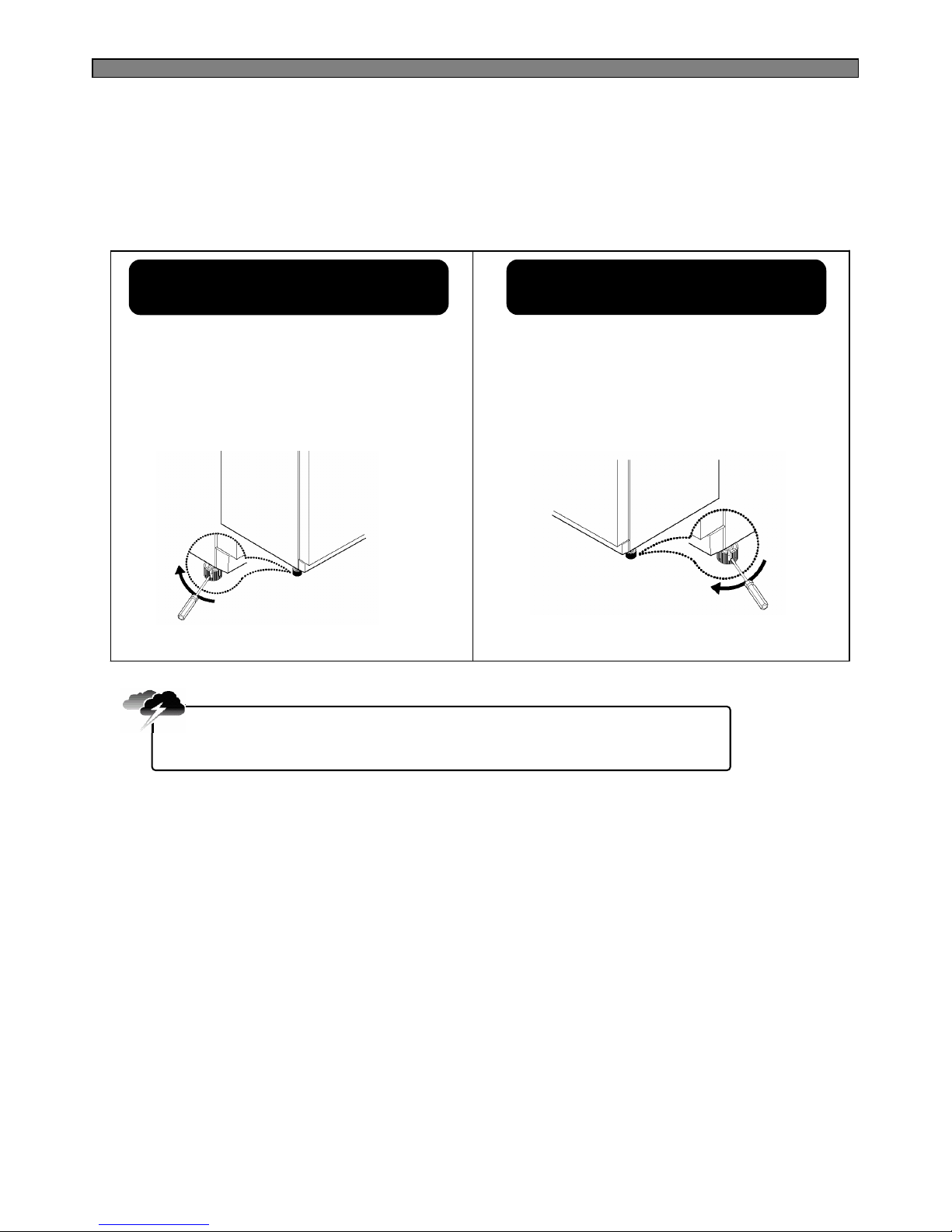
84
11-3. Refrigerator Leveling & Door Adjustment
In case freezer door is lower
than refrigerator door
Insert a screw driver (flat tip) into a groove of the
left wheel (bottom of freezer) and turn it clockwise
until the door is balanced.
(clockwise to raise freezer door ;
counterclockwise to lower)
※Refrigerator must be level in order to maintain optimal performance and desirable front appearance.
(If the floor beneath the refrigerator is uneven, freezer and refrigerator doors look unbalanced.)
Insert a screw driver (flat tip) into a groove of the
right wheel (bottom of refrigerator) and turn it
clockwise until the door is balanced.
(clockwise to raise refrigerator door ;
counterclockwise to lower)
The front of refrigerator needs to be higher just a little than the back for easy
door closing, but if the wheel is raised too much for door balance, i.e. front of
refrigerator is too higher than the back, it can be difficult to open the door.
Caution
In case refrigerator door is lower
than refrigerator door
Page 86
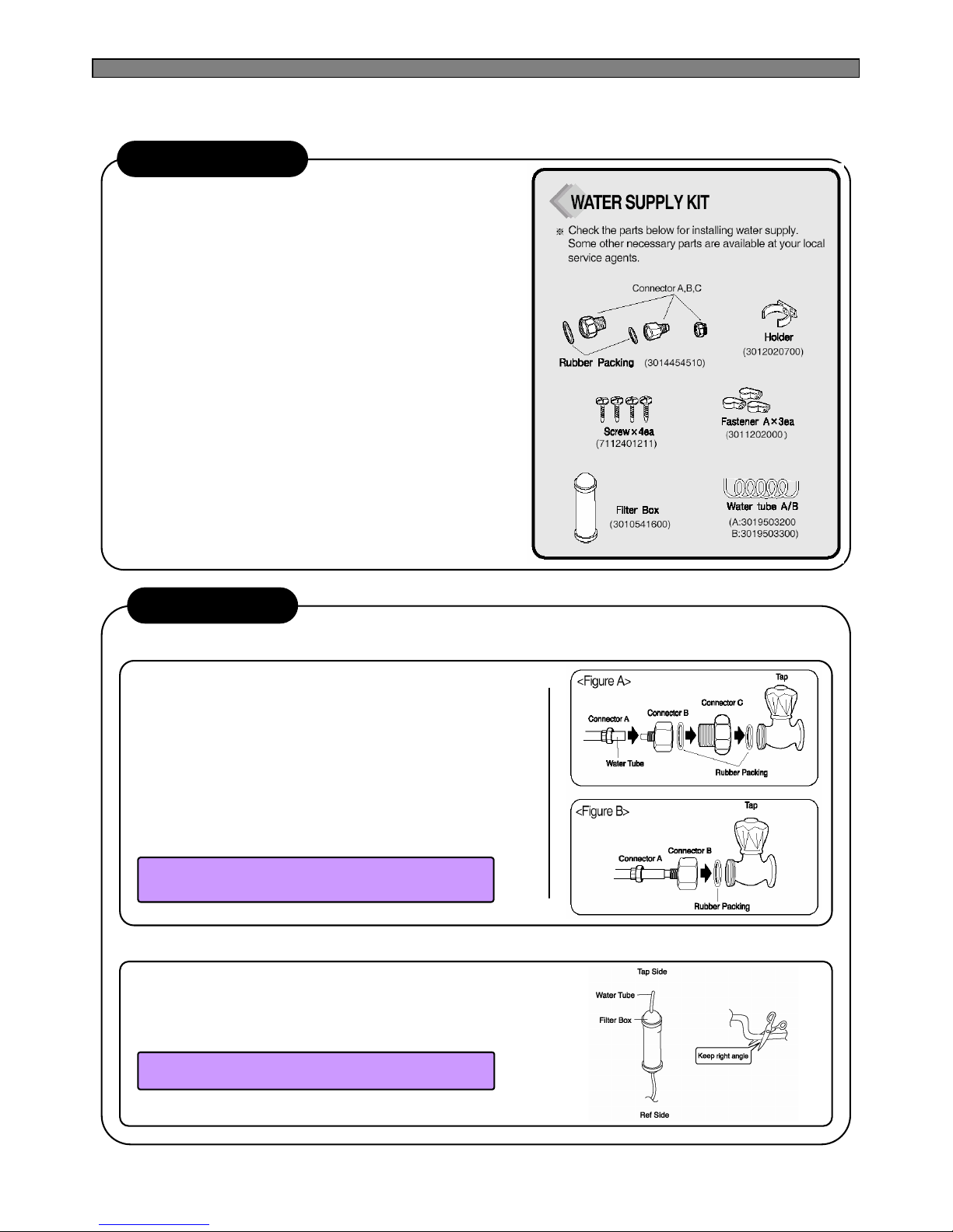
85
11-4. Water Line Installation
1.The water pressure should be 3kgf/cm2 or more to run the
automatic icemaker.
※Checkup your tap water pressure ; if a cup of 180cc is full
within 10 seconds, the pressure is OK.
2.When installing the water tubes, ensure they are not close to
Any hot surface.
3.The water filter only “filters” water ; it does not eliminate any
bacteria or microbes.
4.If the water pressure is not so high to run the icemaker, call the
local plumber to get an additional water pressure pump.
5.The filter life depends on the amount of use. We recommend
you replace the filter at least once every 6months.
※When attaching the filter, place it for easy access (removing
& replacing)
6.After installation of refrigerator and water line system, select
[WATER] on your control panel and press it for 2~3 minutes to
supply water into the water tank and dispense water.
7.Use sealing tape to every connection of pipes/tubes to ensure
there is no water leak.
8.The water tube should be connected to the cold water line.
How to install Water Line
1. Join connector to water tap
Installation Procedure
1)First lock the main tap water valve.
Check if connector B and C has its own rubber packing ring in it.
2)Join Connector C to the water tap, then Connector B to
connector C with a wrench or spanner.
3)Insert water pipe into Connector-B and join Connector-A with a
wrench or spanner.
4)In case Connector-C does not fit water tap join Connector-B
directly to the tap. (See Figure B.)
※If no connector fits water tap, call your local service.
5)Unlock main tap water valve, open tap water and check if any
water leaks on each joins.
Place the rubber washer inside the tap connector and
screw onto the water tap.
2. Get ready to install water line
1) Measure an approximate distance between the filter and the
Water Tube and cut the tube off filter vertically.
2) Connect the tubes to the filter as the figure shows.
Leave a sufficient distance when cutting the tubes.
Page 87
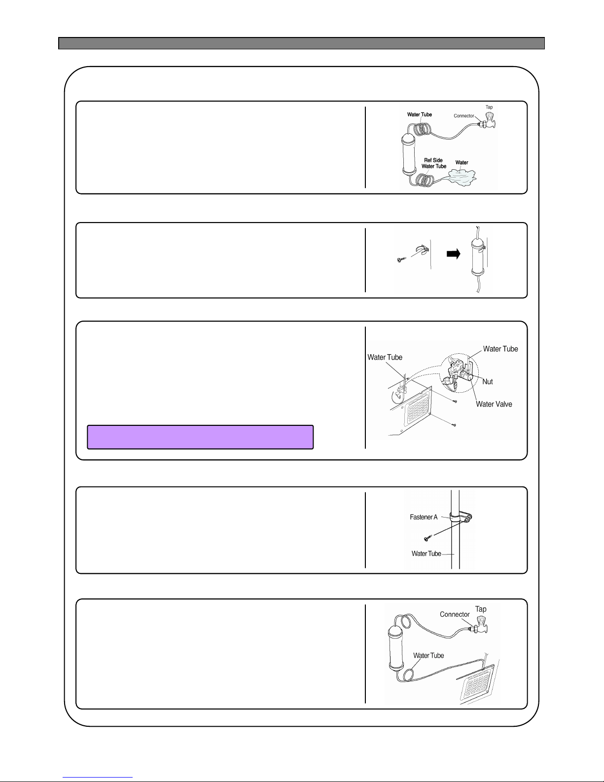
86
3. Remove any substance from filter
1) Open the main tap water valve and check if water comes out of
the Water Tube.
2) Check if the Water Valve is open in case water does not come out.
3) Leave the valve open until clean water is coming out.
※Initial water may contain some substances out of filter
(manufacturing process).
4. Attach the filter box
1)Screw and fasten the filter holder to the left/right side of the back of
refrigerator.
※In case the holder is not fastened well, remove the back paper
of the tape on the filter holder and attach it.
2)Insert the filter box into the holder.
5. Connect water tube
1)Remove the rear cover at the bottom back of the refrigerator.
2)
Insert the fastening ring into the Water tube.
(Be careful to follow the direction of the nut.)
3)Insert the Water Tube into the top of Water Valve, turn the nut
clockwise to fasten it. (The Water valve is to the right of the motor.)
4)Check for any bent tubes or water leaks; if so, re-check instalation
procedure.
5)Replace the rear cover. (The Water Tube should be placed
between the groove of the refrigerator back and motor cover.)
Set the tube upright as the figure shows.
6. Fasten water tube
1) Fasten the Water Tube with the [Fastener A] .
2) Check if the tube is bent or sqeezed. If so, set it right to
prevent any water leak.
7. After installation
1) Plug the refrigerator, press the [WATER] button on the control
panel for 2~3 minutes to remove any air (bubble) in the pipes
and drain out the initial water.
2) Check the water leak again through the water supply system
(tubes, connectors and pipes) Rearrange the tubes again
and do not move the refrigerator.
Page 88
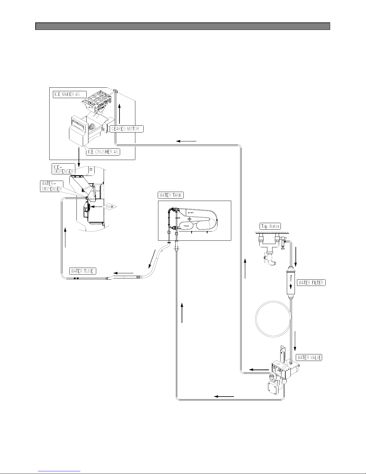
87
11-5. Dispenser Water Flow
Page 89
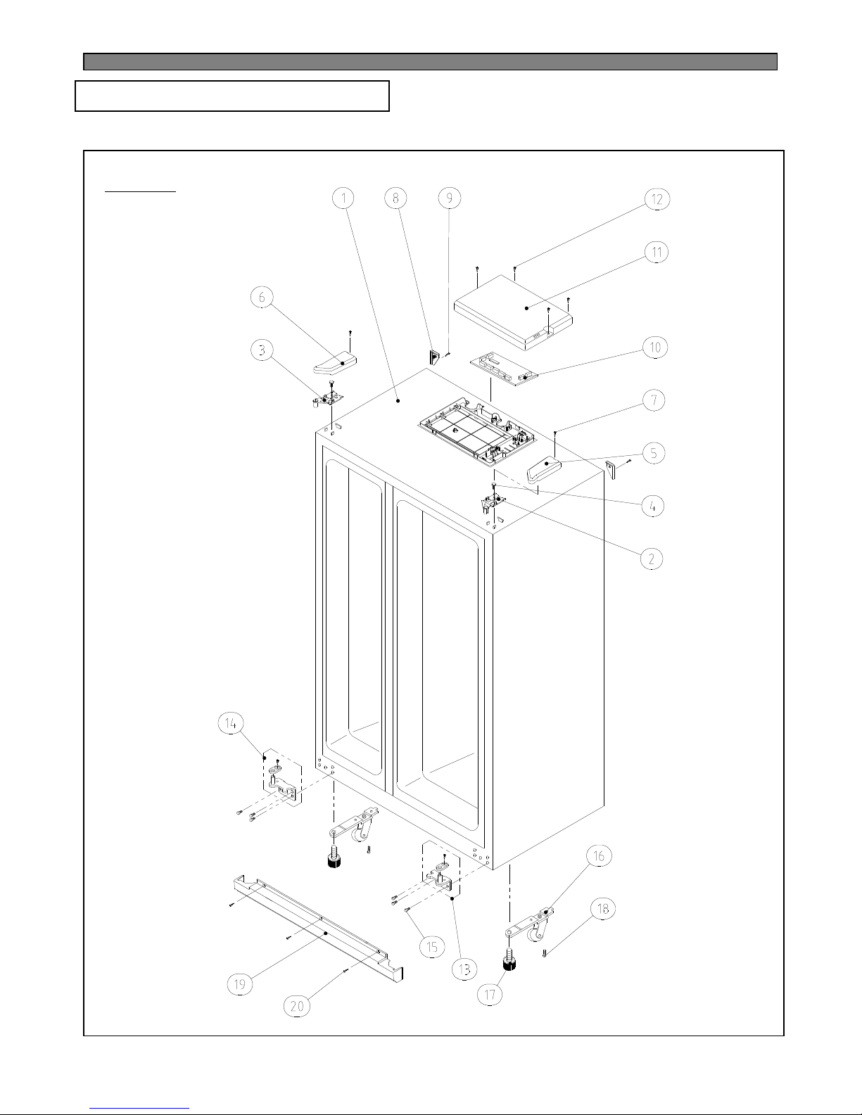
88
CABINET
12-1. FRS(N)-U20IA
12. EXPLODED VIEW & PARTS LIST
Page 90
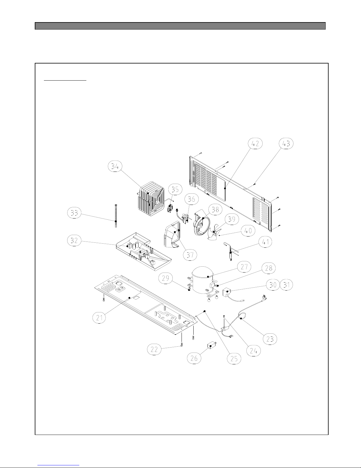
89
MECH ROOM
Page 91
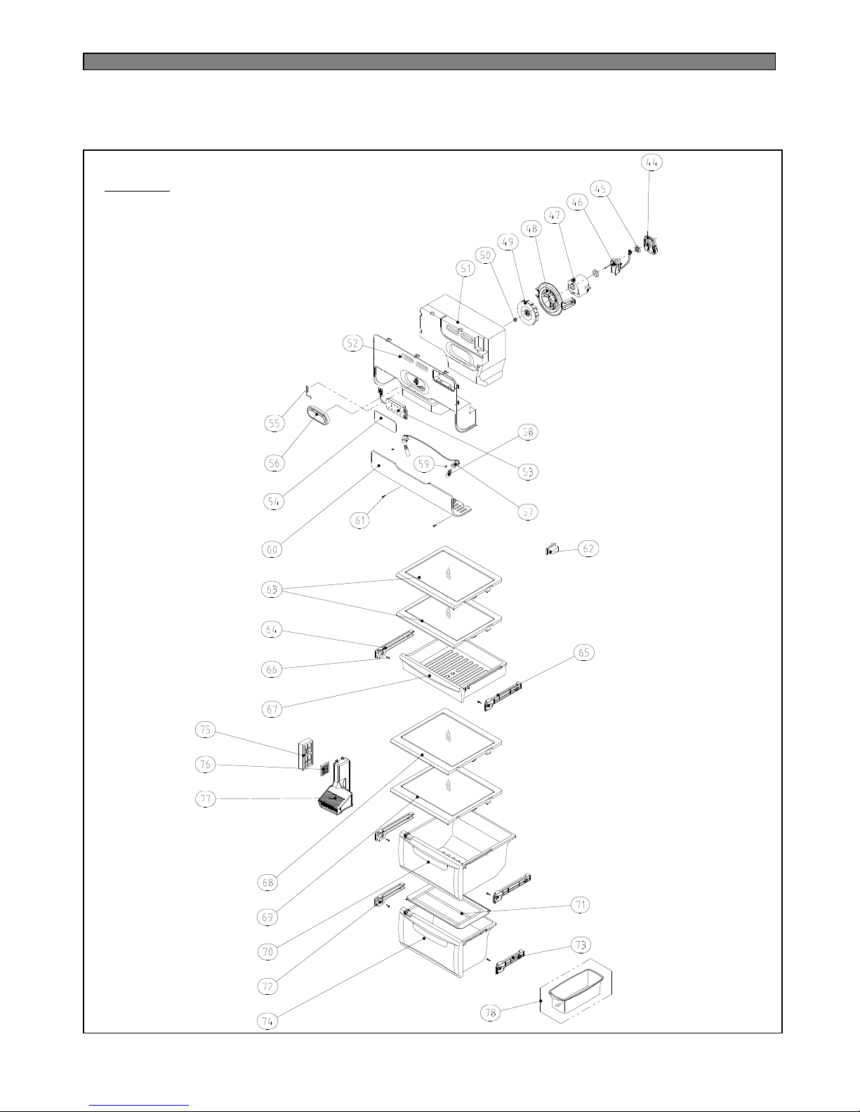
90
R ROOM
Page 92
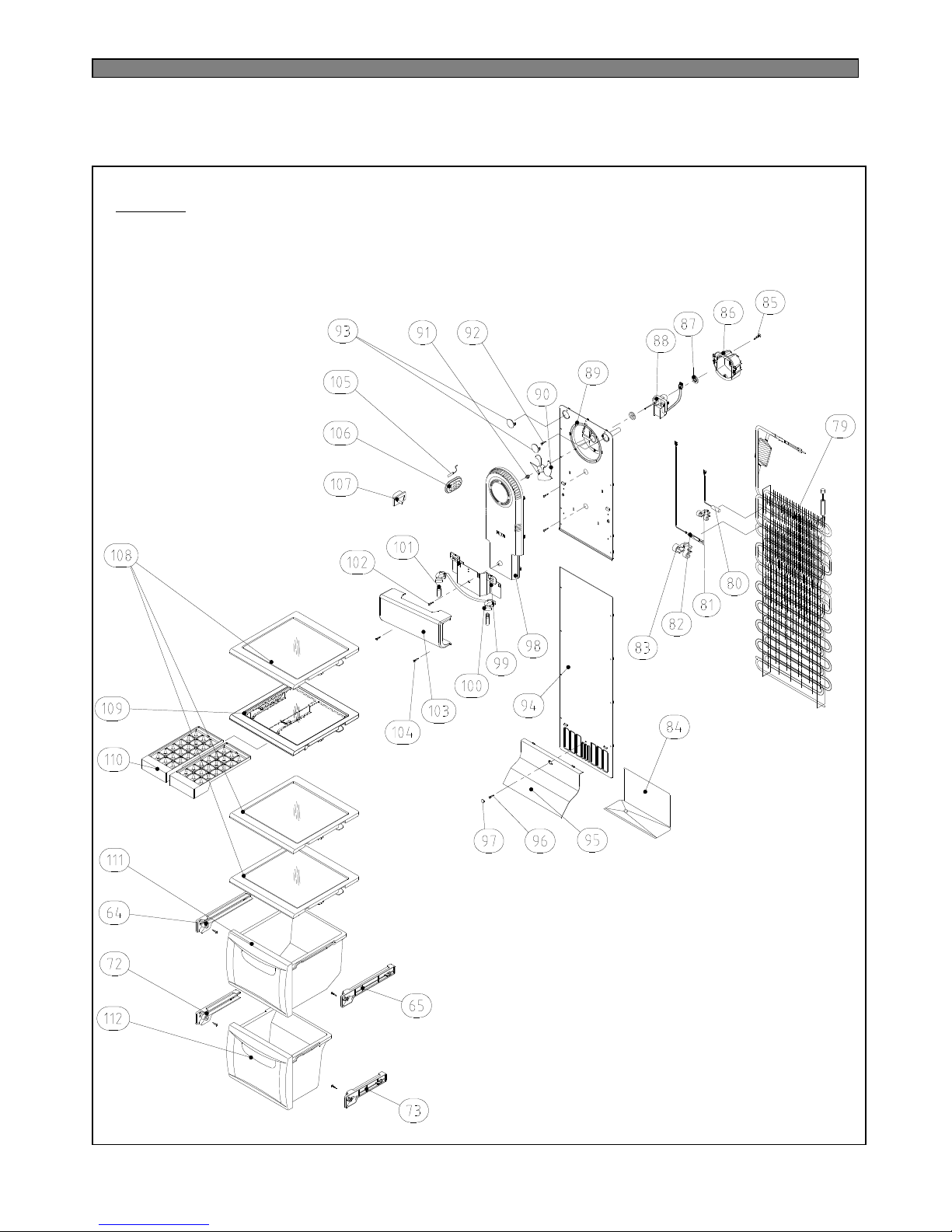
91
F ROOM
Page 93
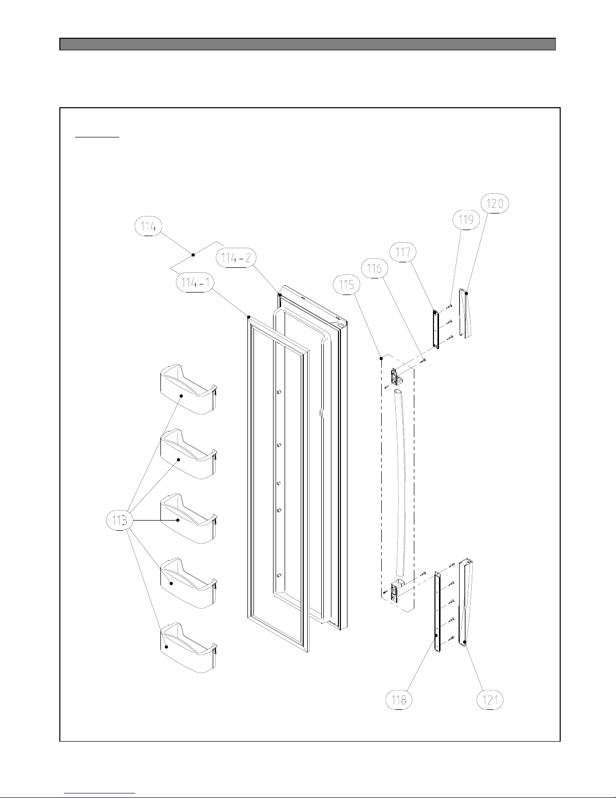
92
F DOOR
Page 94
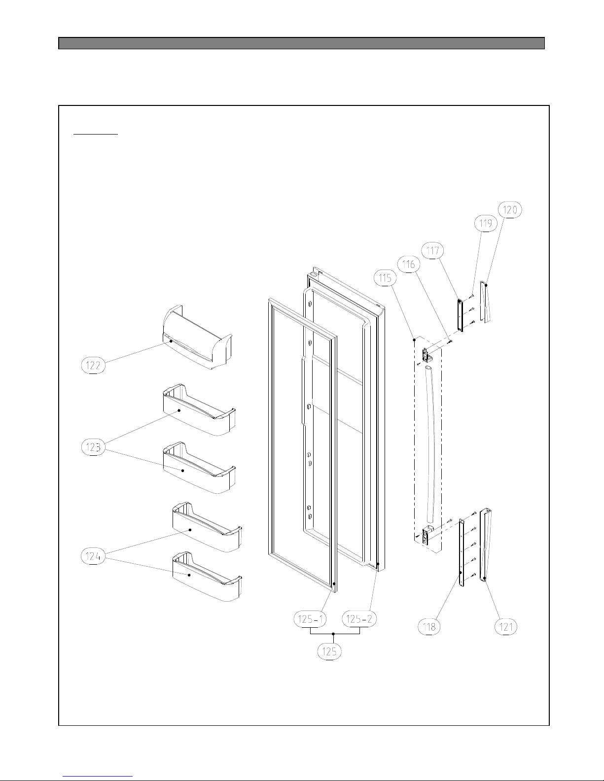
93
R DOOR
Page 95
94
REMARK
SPECIFICATION
Q'ty
PART NAME
PART CODE
NO
ABS OD3.17XD1501FAN301183470039
PP1M/BELL A301850020038
PP1M/BELL B301850030037
DC-2213DWCA-31MOTOR C FAN AS301591610036
PP1FIXTURE MOTR301202170035
TSW OD4.76XT0.71PIPE WICON AS301446151034
PE FRB-5970NB
1HOSE DRN B301320171033
PP1CASE VAPORI AS301118130032
DS3-3NORYL S/S1COVER RELAY381140210031
265RHB,3301SWITCH P RELAY AS301812960030
NBR4RUBBER ABSORBER COMP301010160029
SK-5, T0.84SPECIAL WASHER301600250028
MK183Q-L2U1COMP3956183D5027
400VAC 5UF1CAPACITOR RUN301640192026
PAN 4X10 SW BSNI1SCREW MACHINE705140106525
T1 TRS 4X12 MFZN1SCREW TAPPING711240121124
FRU-571I1CORD POWER AS301134670023
T2 M6.5X204SPEICAL BOLT301600330022
FRU-571I1BASE COMP AS301034040021
T2 TRS 4X16 MFZN3SCREW TAPPING714240151120
PP1COVER CAB BRKT301144720019
6X22 SWCH22A(YL)2SPECIAL BOLT *T301600124018
PP2FOOT ADJ AS301210510017
SPCC T3.02BRACKET ADJ FOOT301065720016
6X22 SWCH22A(YL)6SPECIAL BOLT *T301600124015
P/O T5.0 + PAINT1HINGE *U *L AS301292390014
P/O T5.0 + PAINT1HINGE *U *R AS301292400013
T1 TRS 4X12 MFZN4SCREW TAPPING711240121112
PP(V-235)1COVER MAIN PCB BOX301144600011
FRU-571I1PCB MAIN AS30143D606010
T1 TRS 4X12 MFZN2SCREW TAPPING71124012119
PP2CAP CAB COVER30109684008
T1 TRS 4X12 MFZN2SCREW TAPPING71124012117
PP1COVER *T HI *L30114461006
PP1COVER *T HI *R30114462005
6X13 SWCH18A2SPECIAL *T HI BOLT30160423004
PO T3.0+PAINT1HINGE *T *L AS30129243003
PO T3.0+PAINT1HINGE *T *R AS30129244002
FRU-571I1ASSY CAB URT30000577001
Page 96
95
REMARK
SPECIFICATION
Q'ty
PART NAME
PART CODE
NO
CASE+VINYL1CASE EGG AS301117131078
PP1COVER RETURN DUCT301144590077
W40XT5XL401DEO ANTI AS301870180076
CASE+SILK+FRAME+KNOB1CASE VEGETB C AS301111470075
ABS2GUIDE CASE C *R AS301252980074
ABS2GUIDE CASE C *L AS301252970073
GPPS1COVER VEGETB CASE B301144670072
CASE+SILK+FRAME+KNOB1CASE VEGETB B AS301111460071
FRAME+NUDE GLASS+FIX1SHELF R B AS301784291070
FRAME+NUDE GLASS+FIX1SHELF R C AS301784330069
GPPS1CASE CHILD301118570068
T2S TRS 4X16 MFZN10SCREW TAPPING712240161167
ABS3GUDIE CASE A *R AS301251460066
ABS3GUIDE CASE A *L AS301251450065
FRAME+NUDE GLASS+FIX2SHELF R A AS301784281064
SP201R-7DR1SWITCH LAMP *R301812400063
SM18C2SPECIAL CAP SCREW301600272062
MIPS1WINDOW R LAMP301551080061
T2S PAN 3X82SCREW TAPPING712130081160
AC 240V 25W(S)2LAMP301360250059
250V/1A1SOCKET R LAMP AS301790650058
ABS+SPRAY1COVER R SENSOR301144570057
PBN-43B1SENSOR R AS301480710056
PC-FILM1PLATE INNER CONTROL301457090055
PC-FILM1PANEL INNER CONTROL AS301423520054
PP1COVER DAMP301144440053
F-PS1INSU DAMP AS301335730052
SUS 3041CLAMP FAN301120051051
ABS OD3.17XD1101FAN R301183540050
PP(NATURAL)1FIXTURE MOTOR S1301202380049
PP(NATURAL)1FIXTURE MOTOR S2301202390048
D4612AAA201MOTOR R FAN AS301591600047
NBR2ABSORBER MOTOR301010710046
PP(NATURAL)1FIXTURE MOTOR S3301202370045
FRU-571I1FRAME CHECK VALVE AS301221410044
T1 TRS 4X12 MFZN7SCREW TAPPING711240121143
SBHG T0.351COVER MACH ROOM AS301149700042
C1220T-M OD19.05XL1351DRYER AS301680810041
SUS 3041CLAMP FAN301120050040
Page 97
96
REMARK
SPECIFICATION
Q'ty
PART NAME
PART CODE
NO
FRU-571I1ASSY F DR URT3000057900110-2
PVC1GASKET F DR AS3012318800110-1
FRU-571I1ASSY F DR3000060400110
HIPS+SILK5POCKET F3019026600109
CASE+SILK+FRAME1CASE F B AS3011114900108
CASE+SILK+FRAME1CASE F A AS3011114800107
PP2CASE ICING3011186300106
FRAME+NUDE GLASS+FIX1SHELF F ICE AS3017842700105
FRAME+NUDE GLASS+FIX3SHELF F AS3017842610104
SP201R-7DL1SWITCH LAMP *L3018124010103
ABS1COVER F SENS3011442600102
PT-381SENSOR F AS3014807000101
SM18C2SPECIAL CAP SCREW3016002720100
MIPS1WINDOW F LAMP301551070099
T1 TRS 4X12 MFZN1SCREW TAPPING711240121198
240V 25W1LAMP301360250097
250V 1A1SOCKET F LAMP AS301790660096
SGCC T0.81PLATE F LAMP301453190095
FRU-571I1COVER F FAN AS300140170094
HIPS2CAP F LOUVER301092460093
T2S TRS 4X16 MFZN1SCREW TAPPING712240161192
HIPS1COVER F RETURN301144320091
HIPS1LOUVER F B AS301892150090
HIPS2CAP F LOUVER B301096860089
T2S TRS 4X16 MFZN3SCREW TAPPING712240161188
SUS 3041CLAMP FAN301120051087
ABS OD3.17XD1301FAN301183450086
ABS1LOUVER F A301892130085
D4612AAA211MOTOR F FAN301591590084
NBR2ABSORBER MOTOR301010710083
HIPS1FIXTURE MOTOR A301200780082
T2S TRS 4X12 MFZN1SCREW TAPPING712240121181
GA1GUIDE DRN301252900080
PP1FIXTURE FUSE TEMP4017Z9059079-5
AC250V 10A 77C1FUSE TEMP AS301720200079-4
PP1FIXTURE D SENS301202360079-3
PBN-431SENSOR D AS301480690079-2
AC220V/ 192W1HEATER SHEATH AS301281830079-1
FRU-571I1EVA AS301705350079
Page 98
97
REMARK
SPECIFICATION
Q'ty
PART NAME
PART CODE
NO
FRU-571I1ASSY R DR URT3000058000121-2
PVC1GASKET R DR AS3012318900121-1
FRU-571I1ASSY R DR3000060500121
HIPS+SILK2POCKET R *S3019026900120
HIPS+SILK2POCKET R3019026800119
POCKET+COVER1POCKET DAIRY AS3019027500118
ABS+SPRAY1COVER HNDL DECO *U3011446500117
ABS+SPRAY1COVER HNDL DECO *T3011446400116
T1 TRS 4*12 MFZN8SCREW TAPPING7112401211115
HIPS1BASE HANDLE *U3010339600114
HIPS1BASE HANDLE *T3010339500113
WASR+TRS5X16 MFZN2SPECIAL SCREW3016002700112
FRU-571I1HANDLE AS3012641500111
Page 99
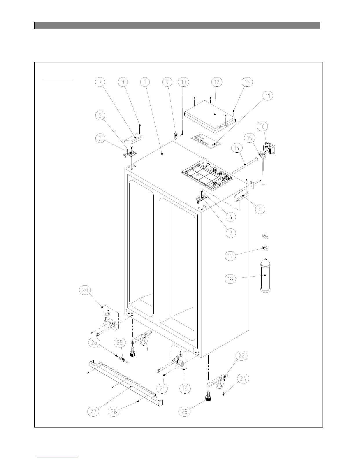
98
CABINET
12-2. FRS(N)-U20DA
Page 100
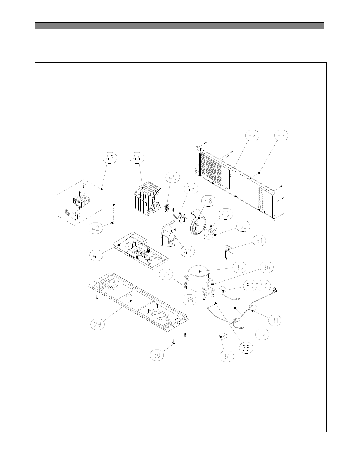
99
MECH ROOM
 Loading...