

Page 1
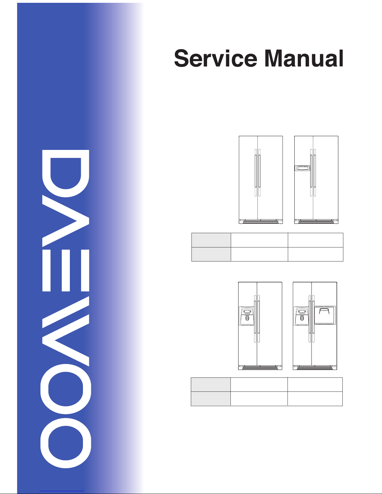
Refrigerator
S/M No:
Caution
In this manual, some parts can be changed for improving their performance without notice.
So, If you need the latest parts information, please visit and refer to PPL (Parts Price List) ]
in Service Infromation Center. ( http://svc.dwe.co.kr )
Aug. 2011.
Refrigerant Type
(R-134a)
FRS-U20IV..
FRN-U20IV.. FRN-U20BV..
FRS-U20BV..
FRS-U20DV..
FRN-U20DV.. FRN-U20FV..
FRS-U20FV..
Refrigerant Type
(R-600a)
Refrigerant Type
(R-134a)
Refrigerant Type
(R-600a)
Page 2
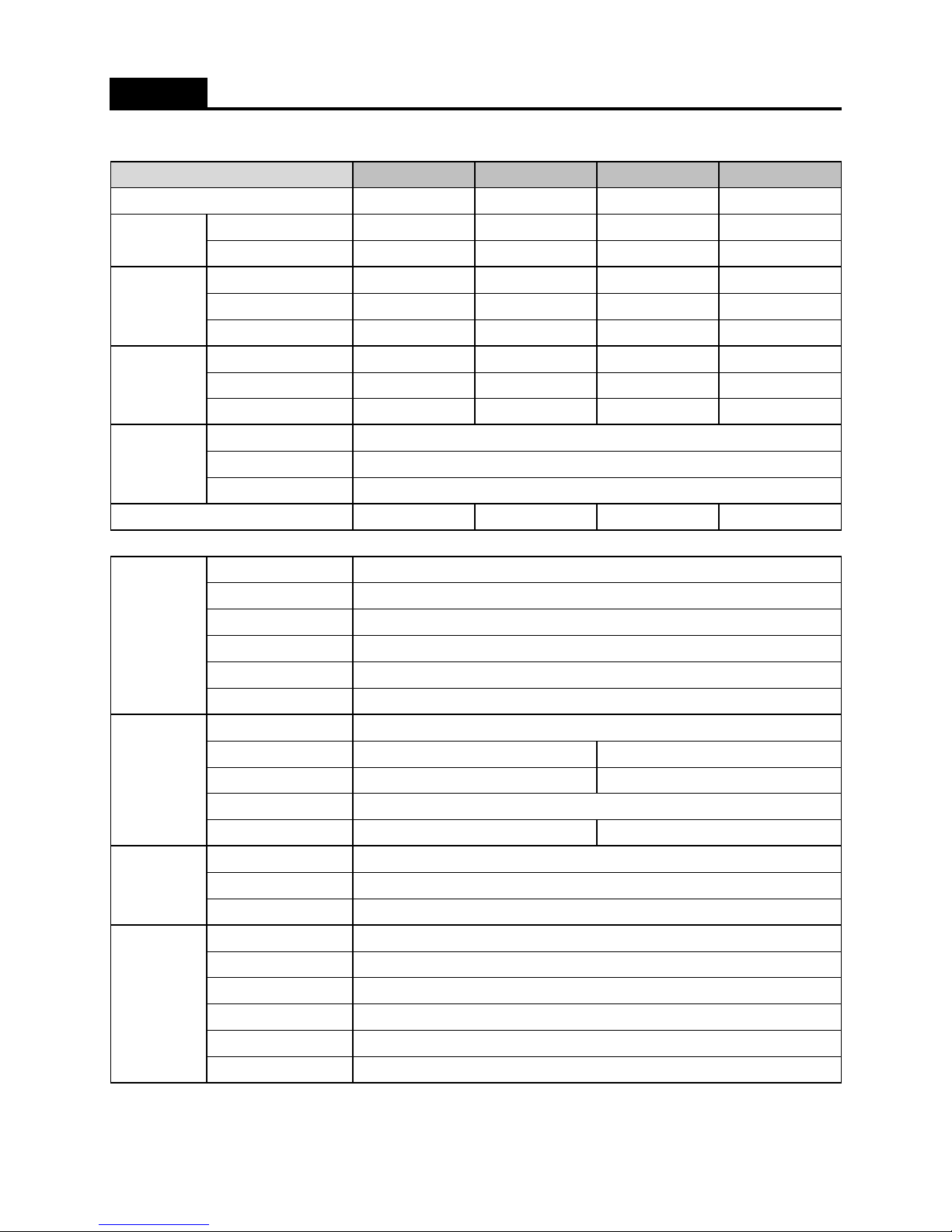
1. Specification
Dispenser
H/Bar
Total
Freezer
Refrigerator
Total
Freezer
Refrigerator
Width (mm)
Depth (mm)
Height (mm)
Refrigerant Type
Refrigerant Charge
Evaporator Type
Condenser Type
Dryer
Capillary Tube
Defrost Heater
Dispenser Heater
Water Pipe Heater
Main Duct Heater
Home Bar Heater
Defrost Sensor
Freezer Sensor
Refrigerator Sensor
Fuse Temp. (Defrost)
Freezer Fan Motor
Refrigerator Fan Motor
Condenser Fan Motor
Freezer Lamp
Refrigerator Lamp
377
227
O
356
AC 220V / 10W
AC 220V / 7W
AC 220V / 5W
AC 220V / 5W
175
531
FRU-54VF..
U20FV..
604618
O
U20DV..
O
xx
U20BV..
Electronic Part
Heater
Sensor
Feature
xx
104
x
354
x
FRU-57VB.. FRU-54VD..
Cooling Cycle
Weight (kg)
Gross Vol.
(ISO 15502)
Storage Vol.
(ISO 15502)
Diemension
Factory No.
Buyer No.
201
618
241
377
555
U20IV..
FRU-57VI..
Molecular Sieve xH-9
104
Fan Cooling System
Fin Type
531
604
227
377377
241
117
356354
555
175201
AC 250V, 10A, 77C
x
PT-38
903
730.5
1790
x
R-600a or R-134a
AC 220V / 192W
115
PBN-43
ID0.7 x T0.55 x L2200
SPECIFICATIONS
25W x 2EA
25W x 1EA
DC 13V, 1100rpm
DC 13V, 1850rpm
PBN-43
76g or 190g
DC 13V, 2050rpm
1
Page 3
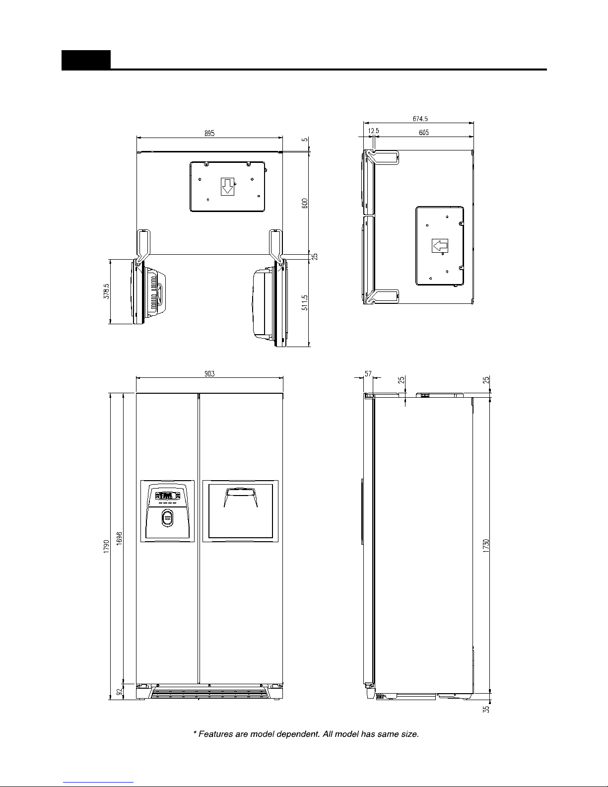
2. External Size
SPECIFICATIONS
2
Page 4
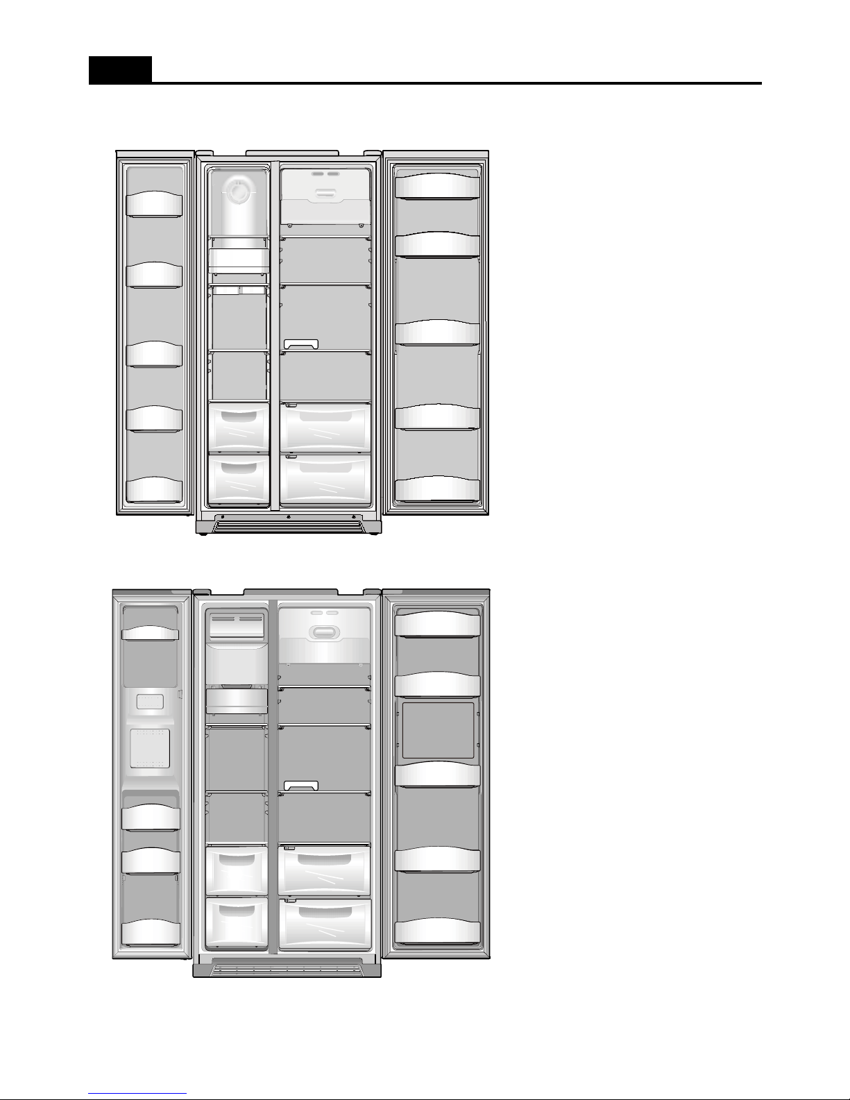
3. Interior Parts
3-1. Basic Models
SPECIFICATIONS
1
2
3
4
5
6
7
8
9
10
11
12
1) Freezer Pocket
2) Freezer Shelf
3) Freezer Lamp
( 25W x 1ea )
4) Ice Tray
5),6) Freezer Case
7) Refrigerator Lamp
( 25W x 2ea )
8) Refrigerator Shelf
9) Egg Tray
10), 11) Refrigerator Case
12) Refreshment Pocket
3-2. Dispenser Models (* Homebar is option )
1
3
4
5
6
7
8
9
10
11
12
13
2
14
1) Water/Ice Dispenser
2) Freezer Pocket
3) Ice Storage Case
4) Freezer Lamp
( 25W x 1ea )
5)
FreezerShelf
6),7) Freezer Case
8) Refrigerator Lamp
( 25W x 2ea )
9) Refrigerator Shelf
10) Egg Tray
11), 12) Refrigerator Case
13) Refreshment Pocket
14) Homebar (*Option)
3
Page 5
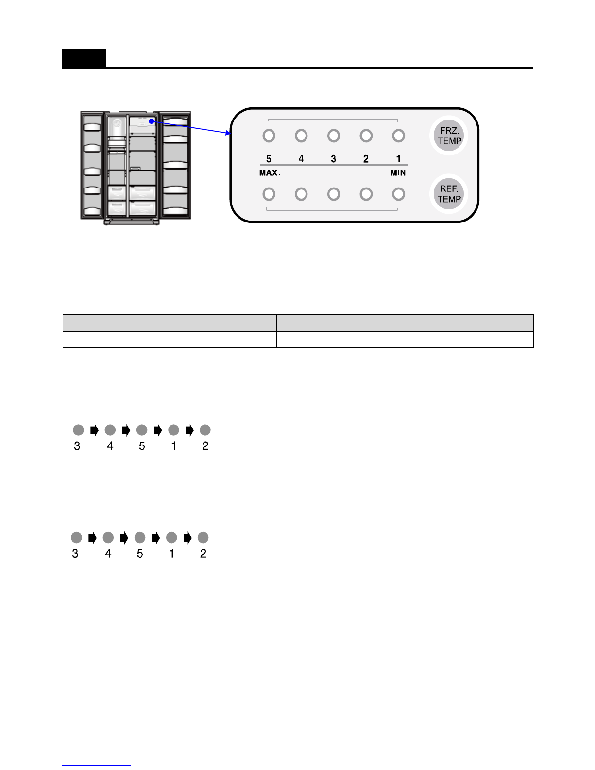
1. Display ( Inner Basic Model )
a Temperature adjustment button for freezer compratment
b Temperature adjustment button for refrigerator compratment
2. Display Control
FUNCTIONS ( DISPLAY_Inner Basic Model )
FCP Cotrol
Temp. Display (Set Temp.) Initial Mode : Freezer / Refrigerator set medium ( 3 / 3 )
a
b
3. FRZ. SET button
1) Temperature control of freezer compartment
2) Initial power plug in : Medium ( 3 )
- Every time you press the FRZ. SET button, the setting temperature changes below order.
4. REF. SET button
1) Temperature control of refrigerator compartment
2) Initial power plug in : Medium ( 3 )
- Every time you press the REF. SET button, the setting temperature changes below order.
4
Page 6
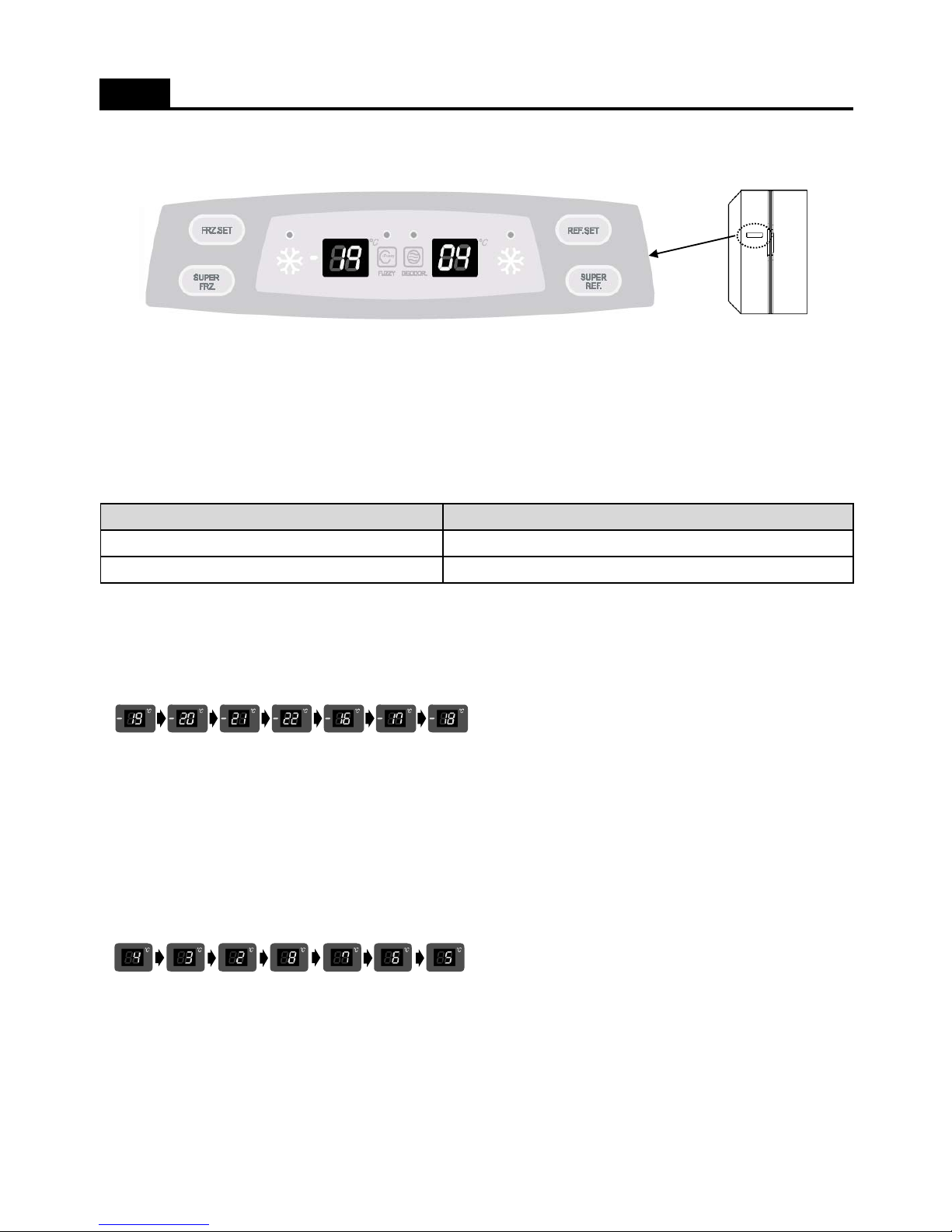
1. Display ( Basic Model )
a Temperature adjustment button for freezer compratment
b Super(Quick) freezer compartment button
c Super(Quick) refrigerator compartment button
d Temperature adjustment button for refrigerator compratment
2. Display Control
FUNCTIONS ( DISPLAY_Basic Model )
FCP Cotrol
Temp. Display (Set Temp.) Initial Mode : Freezer / Refrigerator set medium ( -19C / 4C)
a
b
c
d
3. FRZ. SET button
1) Temperature control of freezer compartment
2) Initial power plug in : Medium ( -19C )
- Every time you press the FRZ. SET button, the setting temperature changes below order.
4. SUPER FRZ. Button
When this button press, the QUICK and Speed icon is flicker 6 times and keep ON.
( By pressing the SUPER FRZ. Button again you can stop this function. )
5. REF. SET button
1) Temperature control of refrigerator compartment
2) Initial power plug in : Medium ( 4C )
- Every time you press the REF. SET button, the setting temperature changes below order.
6. SUPER REF. Button
When this button press, the QUICK and Speed icon is flicker 6 times and keep ON.
( By pressing the SUPER REF. Button again you can stop this function. )
SUPER FRZ, SUPER REF. Icon Button
5
Page 7
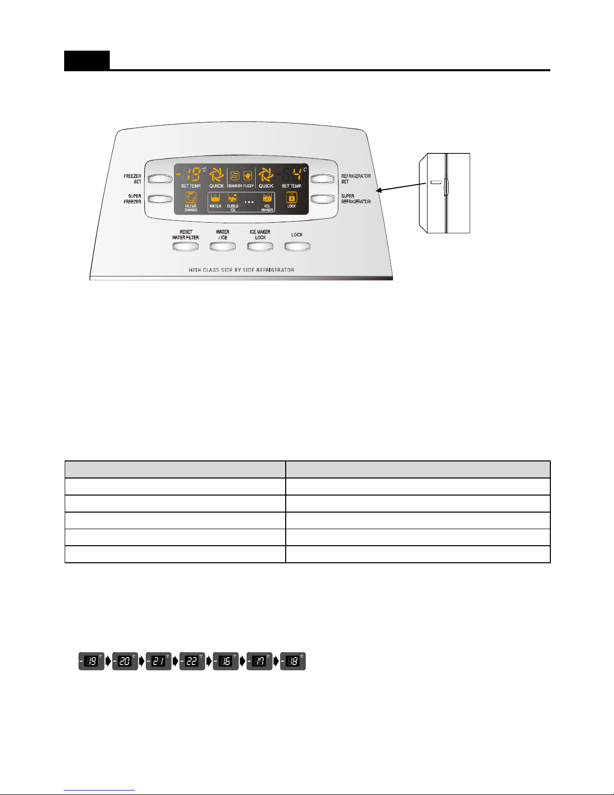
1. Display ( Dispenser Type )
a Temperature adjustment button for freezer compratment
b Super(Quick) freezer compartment button
c Reset water filter button after exchanging the filter
d Dispenser selction button. ( Water / Cubed ice )
FUNCTIONS ( DISPLAY_Dispenser Model )
a
b
c
e
h
g
d
f
e Ice maker lock button
f Children lock button ( Hold 3 sceconds )
g Temperature adjustment button for refrigerator compratment
h Super(Quick) refrigerator compartment button
2. Display Control
3. FRZ. SET button
1) Temperature control of freezer compartment
2) Initial power plug in : Medium ( -19C )
- Every time you press the FRZ. SET button, the setting temperature changes below order.
4. SUPER FRZ. Button
When this button press, the QUICK and Speed icon is flicker 6 times and keep ON.
FCP Cotrol
Temp. Display (Set Temp.)
SUPER FRZ, SUPER REF. Icon
WATER / CUBED ICE
KEY LOCK ICON
FILTER CHANEGE LED AFTER 6 Month, LED ON
Initial Mode : Freezer / Refrigerator set medium ( -19C / 4C)
Button
Button
Button
( By pressing the SUPER FRZ. Button again you can stop this function. )
6
Page 8
5. REF. SET button
1) Temperature control of refrigerator compartment
2) Initial power plug in : Medium ( 4C )
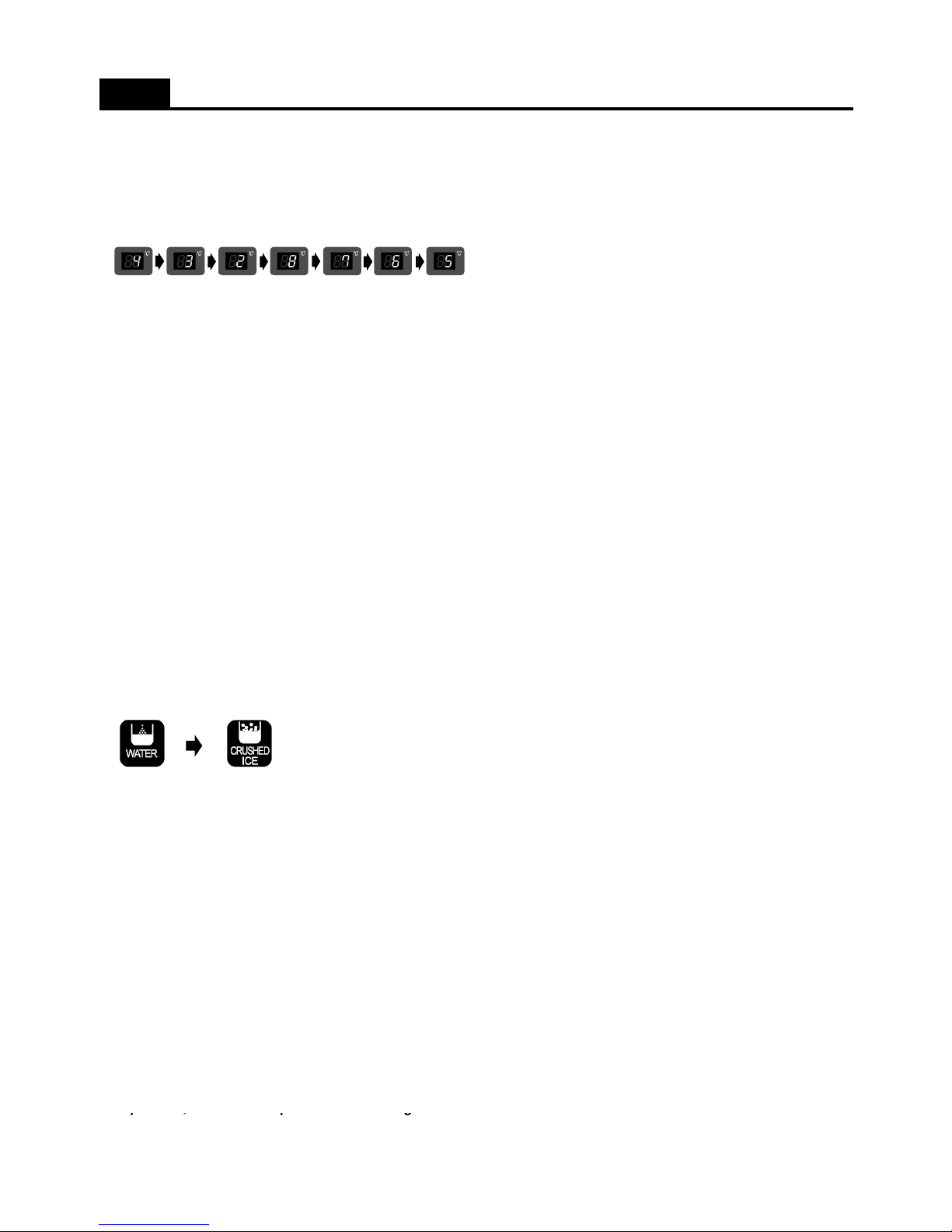
- Every time you press the REF. SET button, the setting temperature changes below order.
6. SUPER REF. Button
When this button press, the QUICK and Speed icon is flicker 6 times and keep ON.
( By pressing the SUPER REF. Button again you can stop this function. )
7. RESET WATER FILTER
After 6 month of first power input, 'Change Filter Icon' is on. When the time comes to change follow the steps.
1) Push the Lock button.
2) Push the 'Filter Reset' button for 3 seconds. Then 'Change Filter'icon is off.
8. WATER/ICE select
FUNCTIONS ( DISPLAY_Dispenser Model )
1) WATER / CUBED ICE mode available.
2) Every the button press, the order is WATER - CUBED ICE
3) The initial mode is WATER.
9. ICE MAKER LOCK
1) Press the 'Dispenser' button continue. ( Press again, the mode is OFF. )
2) When cleaning the ice storage case or when not use for a long period of time.
9. LOCK button
1) When lock the other buttons, press this button and LOCK icon is active.
( In this mode other button is unable except LOCK button.)
2) To unlock, push the button again.
< REFERENCE >
: Please wait for 2 ~ 3 seconds in order to take final ice or drops of water when taking out cup from the pressing
switches after taking ice or water.
: The actual inner temperature varies depending on the frood status, as the indicated setting temperature is a target
tem
p
erature, not actual temperautre within refrigerator.
p, p g
7
Page 9
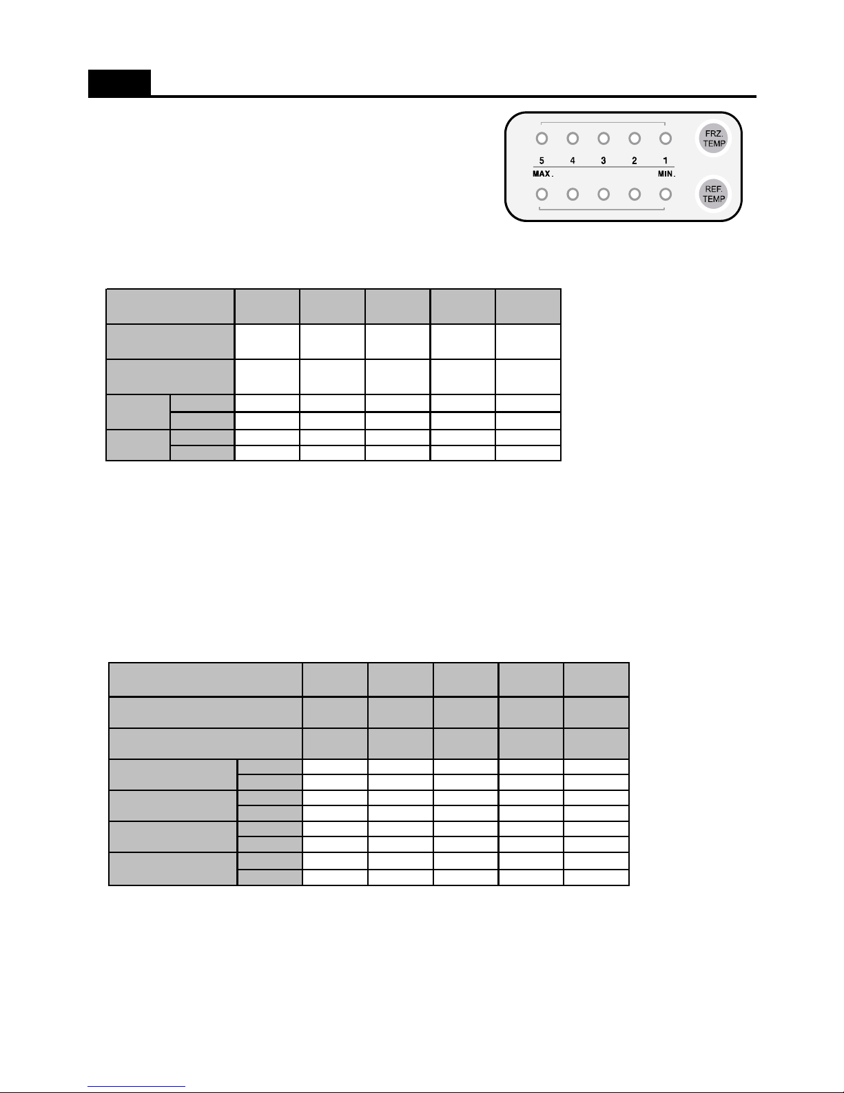
1. Freezer Compartment Control
1) Adjust by the pushing the FRZ.SET button.
2) Compressor & Freezer Fan controlled by each mode ON/OFF point.
3) Freezer Compartment ON/OFF Difference : 2C
- MEDIUM OFF point : -19C
- When Room Temperature (RT) is below 13C, Freezer sensor OFF point 2C up ( so, MEDIUM OFF : -17C )
4) Control Temperature Point in Each Mode
FUNCTIONS ( TEMPERATURE CONTROL )
Initially On 1st Press 2nd Press 3rd Press 4th Press
Sensor On -14.0 -15.5 -17.5 -9.0 -12.0
Sensor Off -16.0 -17.5 -19.5 -11.0 -14.0
Sensor On -12.0 -13.5 -15.5 -7.0 -10.0
Sensor Off -14.0 -15.5 -17.5 -9.0 -12.0
Min
Medium
Min
12
Division
345Display
Normal
RT <= 13C
Control
Medium
Max
Max
Temperature
Medium
2. Refrigerator Compartment Control
1) Adjust by the pushing the REF.SET button.
2) Refrigerator Fan controlled by each mode ON/OFF point.
3) Freezer Compartment ON/OFF Difference : 0.5C
- MEDIUM OFF point : 4.2C
- When Room Temperature (RT) is below 13C, Refrigerator sensor OFF point 2C up ( so, MEDIUM OFF : 6.2C )
4) Control Temperature Point in Each Mode
Initially On 1st Press 2nd Press 3rd Press 4t h P ress
Sensor On 4.7 3.7 2.7 6.7 5.7
Sensor Off 4.2 3.2 2.2 6.2 5.2
Sensor On 6.7 5.7 4.7 8.7 7.7
Sensor Off 6.2 5.2 4.2 8.2 7.2
Sensor On 11.2 10.2 9.2 13.2 12.2
Sensor Off 4.2 3.2 2.2 6.2 5.2
Sensor On 13.2 12.2 11.2 15.2 14.2
Sensor Off 6.2 5.2 4.2 8.2 7.2
1
Division
Display 2
Temperature Medium
Medium
Max
Max Min
Medium
Min
345
Normal
RT <= 13C
Weak refrigeration
Weak refrigeration
& RT <= 13C
8
Page 10
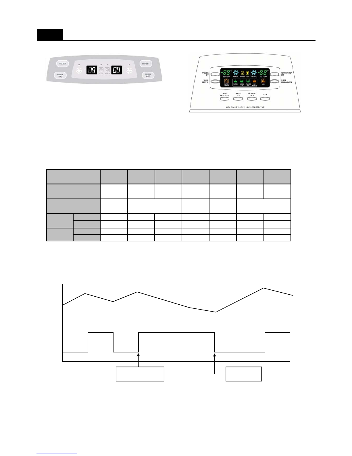
1. Freezer Compartment Control
1) Adjust by the pushing the FRZ.SET button.
2) Compressor & Freezer Fan controlled by each mode ON/OFF point.
3) Freezer Compartment ON/OFF Difference : 2C
- MEDIUM OFF point : -19C
- When Room Temperature (RT) is below 13C, Freezer sensor OFF point 2C up ( so, MEDIUM OFF : -17C )
4) Control Temperature Point in Each Mode
FUNCTIONS ( TEMPERATURE CONTROL )
Initially On 1st Press 2nd Press 3rd Press 4th Press 5th Press 6th Press
Display
-19 -20
Division
Temperature
-18-21 -22
-16 -17
6) SUPER FRZ. (QUICK) Mode
- In this mode, Compressor & Freezer Fan motor is on unconditionally for 150min. ( free of freezer sensor )
Freezer
Sensor
Freezer
Fan On/Off
SUPER FRZ. Start
( SUPER FRZ. MODE )
NORMAL MODE
Start
150MIN
Sensor On -14.8 -15.8 -16.8 -17.8 -11.8 -12.8 -13.8
Sensor Off -16.8 -17.8 -18.8 -19.8 -13.8 -14.8 -15.8
Sensor On -12.8 -13.8 -14.8 -15.8 -9.8 -10.8 -11.8
Sensor Off -14.8 -15.8 -16.8 -17.8 -11.8 -12.8 -13.8
Normal
RT <= 13C
Medium
Medium Max
Max
Medium Min
Control
Min
9
Page 11
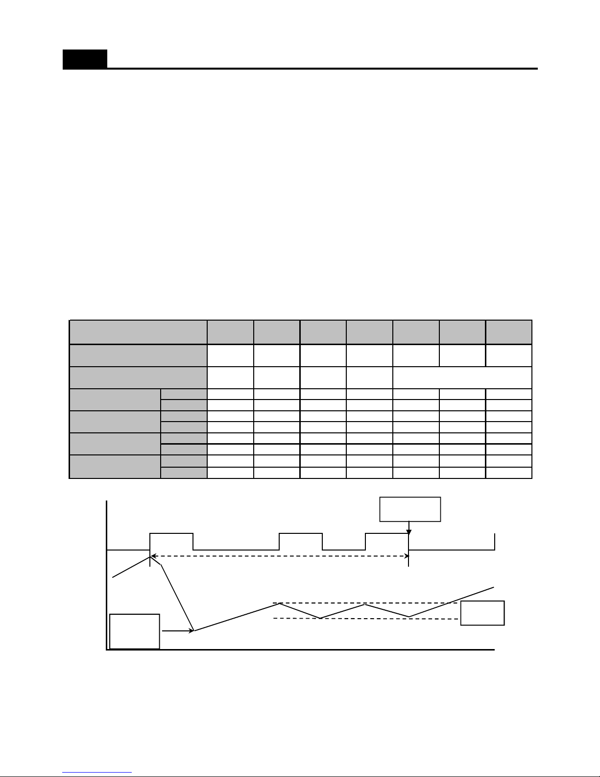
2. Refrigerator Compartment Control
1) Adjust by the pushing the REF.SET button.
LOW - MEDIUM LOW - MEDIUM - MEDIUM MAX - MAX
2) Refrigerator Fan controlled by each mode ON/OFF point.
3) Refrigerator Compartment ON/OFF Difference : 0.5C
- MEDIUM OFF point : 5.2C
- When Room Temperature (RT) is below 13C, Refrigerator sensor OFF point 2C up ( so, MEDIUM OFF : 7.2C )
4) Weak Cooling Prevention Function
- This funtion is free of Freezer sensor.
- When refrigerator compartment reaches the Fan OFF point, the Fan is OFF.
and then Compressor controlled by Freezer sensor.
- Weak cooling temperautre is + 7C in each sensor OFF temperature.
- Weak cooling terminate temperautre is same as each sensor OFF temperature.
6) Control Temperature Point in Each Mode
FUNCTIONS ( TEMPERATURE CONTROL )
Initially On 1st Press 2nd Press 3rd Press 4th Press 5th Press 6th Press
Division
7) SUPER REF. (QUICK) Mode : This mode runs for 40 minutes.
- Until the sensor reaches the Excess Refrigeration OFF point ( -7C), Refrigerator Fan and compressor is ON.
- Until the QUICK Mode ends, the appliance runs with MAX dial mode.
- After QUICK Mode ( about 40 mins ) the normal mode start.
Freezer
Sensor
Excess
Refrigeration
OFF point
ON/OFF
MAX MODE
NORMAL MODE
Start
QUICK MODE (40MIN )
Sensor On 5.7 4.7 3.7 9.7 8.7 7.7 6.7
Sensor Off 5.2 4.2 3.2 9.2 8.2 7.2 6.2
Sensor On 7.7 6.7 5.7 11.7 10.7 9.7 8.7
Sensor Off 7.2 6.2 5.2 11.2 10.2 9.2 8.2
Sensor On 12.2 11.2 10.2 16.2 15.2 14.2 13.2
Sensor Off 5.2 4.2 3.2 9.2 8.2 7.2 6.2
Sensor On 14.2 13.2 12.2 18.2 17.2 16.2 15.2
Sensor Off 7.2 6.2 5.2 11.2 10.2 9.2 8.2
4
Medium
32
Normal
Weak refrigeration
RT <= 13C
Weak refrigeration
& RT <= 13C
Display
Temperature Medium Min
658
Medium Max Max
7
Min
10
Page 12
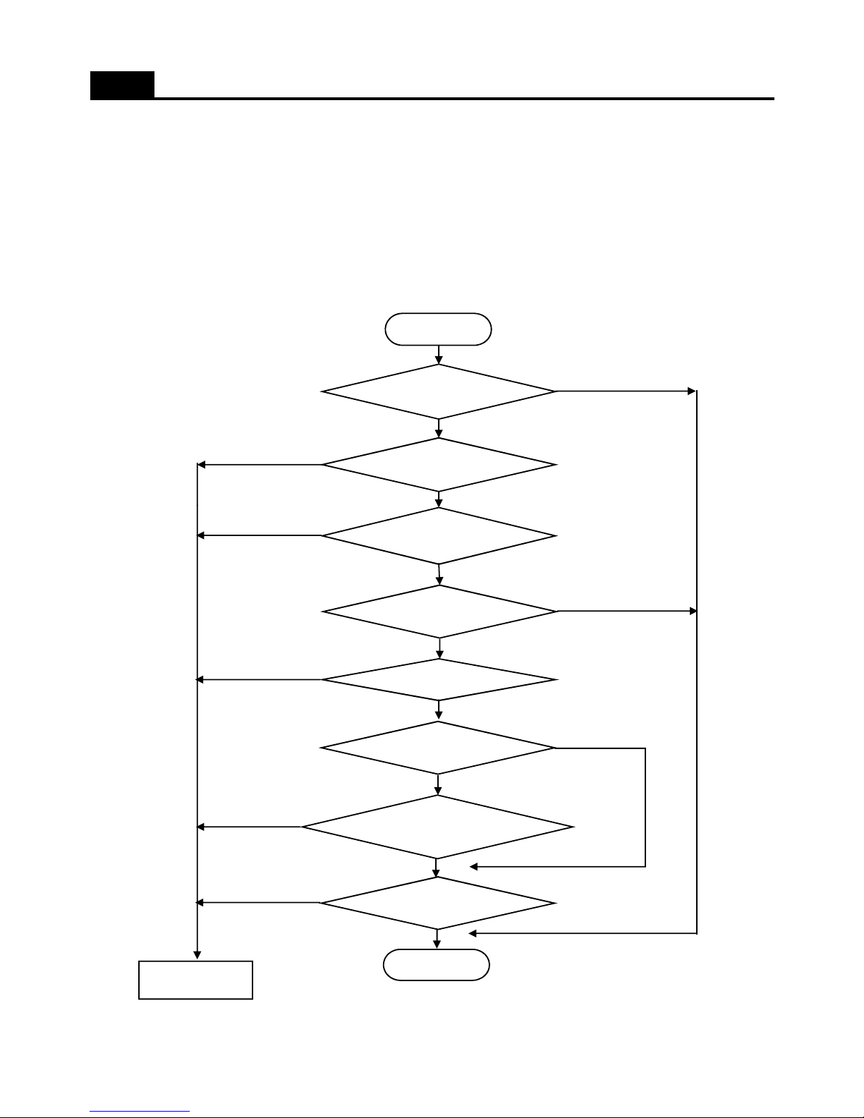
1. When Defrost Mode start?
; When total Compressor runnig time becomes at 6, 8, 10, …, 24hours.
- The compressor runing rate is over 85% every 2 hours.
- Door opening time is over 2 minutes ( Each Freezer / Refrigerator door )
- Total compressor running time ( on time + off time ) is 60hours.
- Any error happens. ( R1, F1, D1, F3, RT-Sensor, C1, Door switch etc. )
( But, F3 error happens then defrost mode start without Pre-cool )
FUNCTIONS ( Defrost Mode )
Compressor runing
Start
Total appiance runing
Yes
No
No
Yes
Compressor runing
Compressor runing
Any error happens
Room temperature is
Compressor runing rate is
over 85% every 2 hours
Door open ( each
End
No
Yes
No
No
No
No
Yes
No
Defrost mode start
Yes
Yes
Yes
Yes
11
Page 13
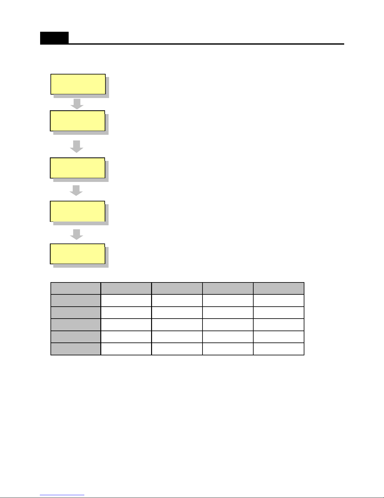
2. Normal Defrost Mode
FUNCTIONS ( Defrost Mode )
PRECOOL
HEATER
DEFROTING
PAUSE
FAN DELAY
1) PRECOOL
- Compressor runs ( to cool down the freezer compartment prior to heater switch on )
for 50minutes or until Freezer sensor temperature reaches -27C
2) HEATER DEFROSTING
- Defrost heater is switch on until Defrost Sensor temperature reaches 13C.
- Heater operation time
; 30 seconds - Heater is ON free of Defrost Sensor.
; 30 minutes - When Defrost Sensor is malfunction. ( D1 error )
; 80 minutes - Heater maximum operation time. ( F3 error )
3) PAUSE
- After Defrost Heater switch OFF, Compressor dosen't run within 7 minutes.
4) FAN DELAY
- Freezer & Refrigerator fan switch on after 5miunuts' cmopressor running.
3. Forced Defrost Mode
1) How to start
( Basic Models Only )
; Press the REF. SET button 5 times while pushing the FRZ. SET button.
( Dispenser Models Only )
- Press the LOCK button.
- Press the Refrigerator Set button 5 times while pushing the Freezer Set button.
2) Except PRECOOL, steps are same as above 2. Normal Defrost Mode.
Normal Mode
PRECOOL
Defrsot Heater
Time
Division
Compressor
Freezer Fan
Refrigerator Fa n
50min
ON
Off
OFF OFF
OFFOFF
OFF
ON
OFF OFF
OFF OFF ON
7min
OFF
PAUSEHEATER DEFROST FAN DELAY
Control
30min ( D1 error )
80min
(
F3 error
)
ON
5min
12
Page 14
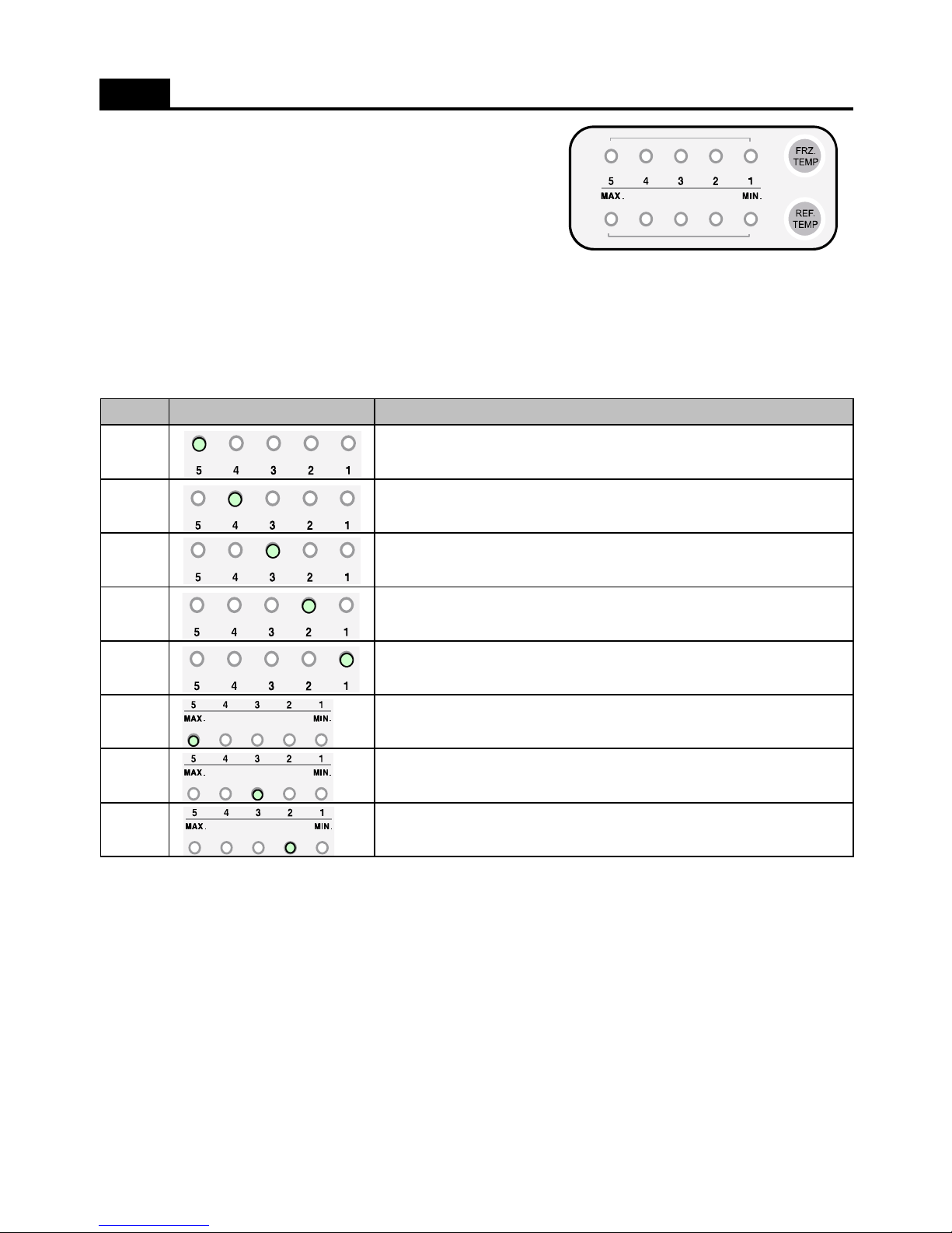
1. How to enter this check mode
; Press the FRZ. SET button 5 times while pushing the REF. SET button.
2. The Front LED displays the current error code ( if happens ).
3. How to exit this mode
1) Press the FRZ.SET button
2) After 4 minutes automatically exit.
4. Error Code
No
1
2
FUNCTIONS ( Error Display_Basic Model )
Display (LED flicker) Remark
Freezer sensor disconnection or short
Refrigerator sensor disconnection or short
3
4
5
6
7
8
; All Error Code reset, when the relative parts turn into normal.
Defrost sensor disconnection or short
Refrigerator Door switch is defective.
Room temperature sensor disconnection or short
Abnormal return after defrosting
Freezer Door switch is defective.
Abnormal or defective cycle
13
Page 15
5. Troubleshooting when error happens
( If the relative parts is normal, Error code display will be reset. )
1) Freezer sensor error
- Cause : Freezer sensor disconnection or short.
- Check point : Measure the resistance between both terminals after separating CN9 of the Main PCB.
If sensor is disconnected or short, change that in the freezer compartment.
2) Refrigerator sensoer error
- Cause : Refrigerator sensor disconnection or short.
- Check point : Measure the resistance between both terminals after separating CN8 of the Main PCB.
If sensor is disconnected or short, change that in the refrigerator compartment.
3) Room temperature sensor error
- Cause : Room temperature sensor disconnection or short.
- Check point : Measure the voltage of sensor part on the Main PCB.
If voltage is 0.5~4.5V, normal. If voltage is 0V (short) or 5V (disconnect), change new one.
FUNCTIONS ( Error Display_Basic Model )
4) Defrost sensor error
- Cause : Defrost sensor disconnection or short.
- Check point : Measure the resistance between both terminals after separating CN9 of the Main PCB.
If sensor is disconnected or short, change that on the evaporator.
5) Refrigerator door switch error
- Cause : When it senses the door open for more than 1 hour.
- Check point : Check the each door switch and exchange.
6) Freezer door switch error
- Cause : When it senses the door open for more than 1 hour.
- Check point : Check the each door switch and exchange.
7) Cycle error
- Cause : When compressor works for over 3 hours although Defrost sensor is over -5C.
- Check point : Refrigerant leakage.
8) Abnormal defrosting end error
- Cause : in case defrosting mode ends after 80 minutes.
- Check point : Measure the resistance between both terminals of the defrost heater.
If the resistance is infinity (disconnection) or 0 ohm (short).
14
Page 16
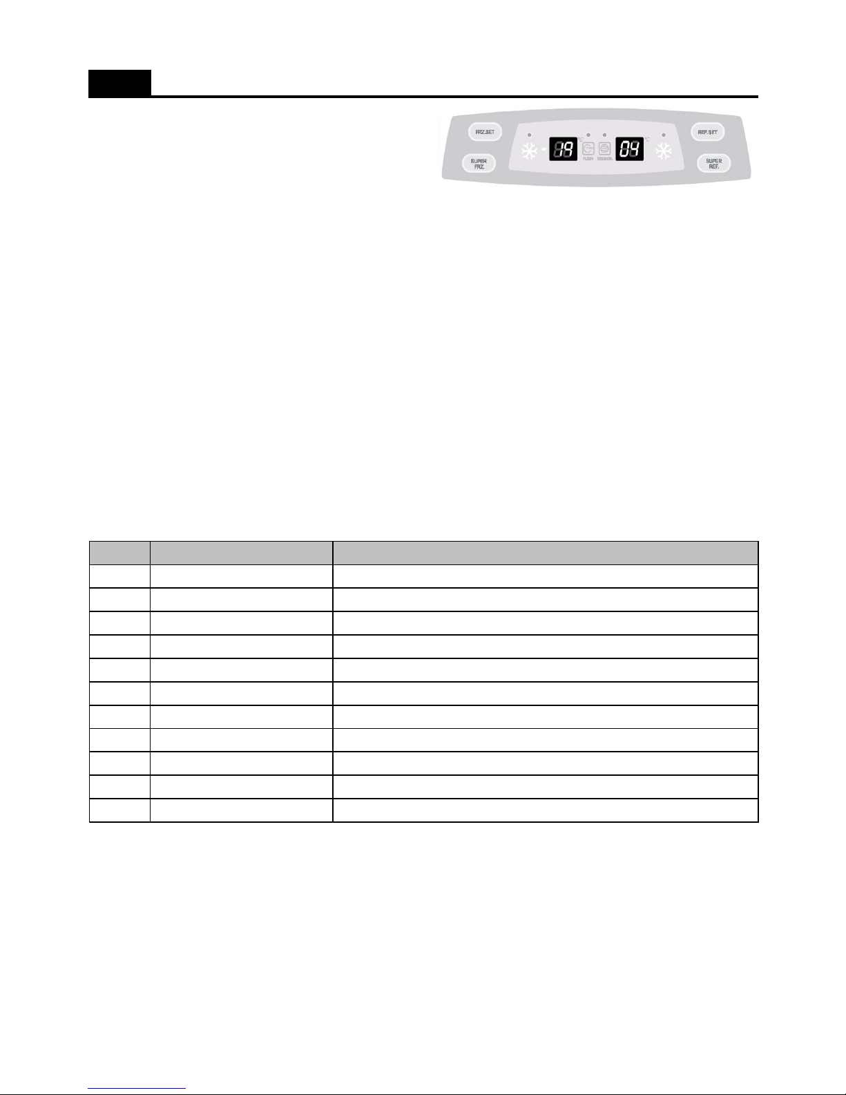
1. How to enter this check mode
; Press the SUPER FRZ. button 5 times while pushing the FRZ. SET button.
2. The Front LED displays the current error code ( if happens ).
; Every time you press the FRZ. Set button, the following value display.
1) The appliance running time. ( From the plug in. )
2) Freezer sensor temperature.
3) Defrost sensor temperature.
4) Refrigerator sensor temperature.
5) Room temperature.
3. How to exit this mode
1) Press the REF.SET button
2) After 4 minutes automatically exit.
FUNCTIONS ( Error Display_Basic Model )
4. Error Code
No
1
2
3
4
5
6
7
8
9
10
11
; All Error Code reset, when the relative parts turn into normal.
r1
Refrigerator sensor disconnection or short
rt
Room temperature sensor disconnection or short
Display (Error Code) Remark
F1
Freezer sensor disconnection or short
dF
Freezer Door switch is defective.
dH
Home Bar Door switch is defective.
d1
Defrost sensor disconnection or short
dr
Refrigerator Door switch is defective.
Co
Pull-Down mode display (No error)
d2
Forced Defrost mode display (No error)
C1
Abnormal or defective cycle
F3
Return after defrosting : abnormal or defective
15
Page 17
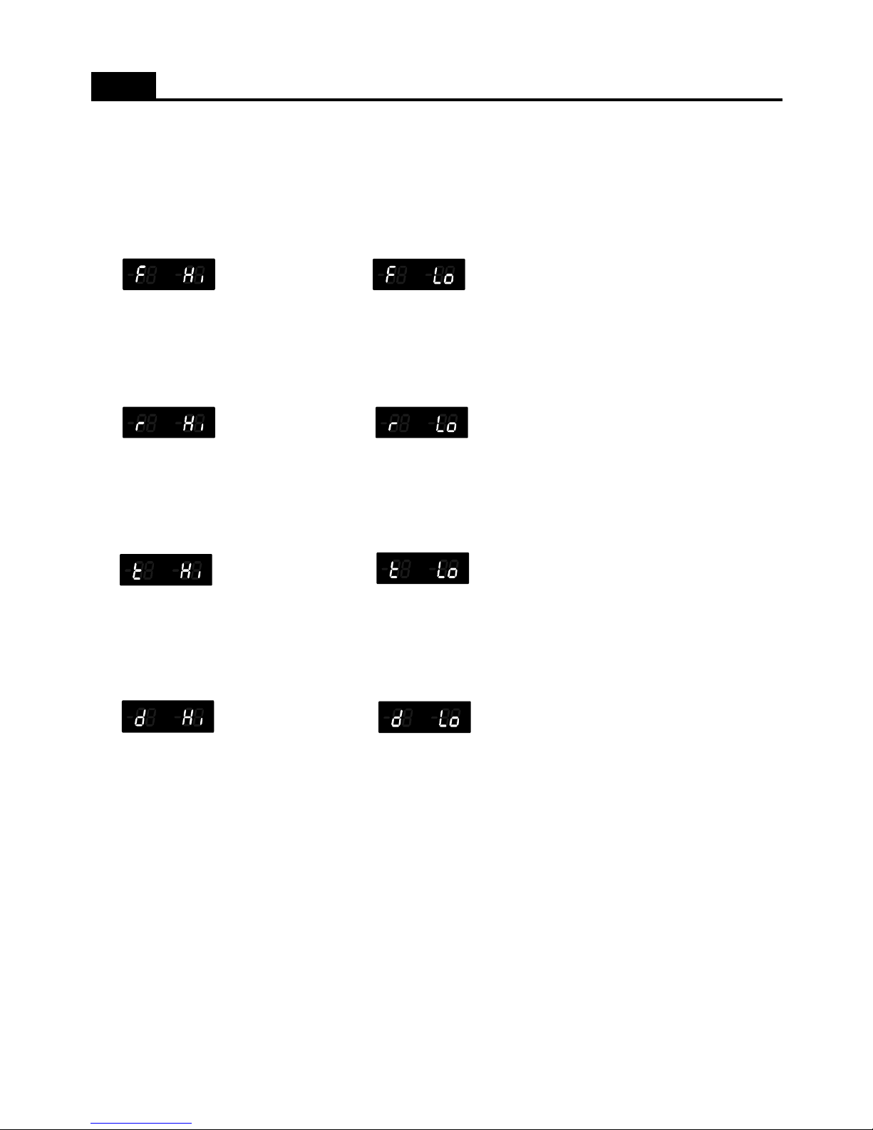
5. Troubleshooting when error happens
( If the relative parts is normal, Error code display will be reset. )
1) Freezer sensor error
- Cause : Freezer sensor disconnection or short.
- Check point : Measure the resistance between both terminals after separating CN9 of the Main PCB.
If sensor is disconnected or short, change that in the freezer compartment.
- Error code display
Freezer sensor is short. Freezer sensor is disconneted.
2) Refrigerator sensoer error
- Cause : Refrigerator sensor disconnection or short.
- Check point : Measure the resistance between both terminals after separating CN8 of the Main PCB.
If sensor is disconnected or short, change that in the refrigerator compartment.
- Error code display
Refrigerator sensor is short. Refrigerator sensor is disconneted.
3) Room temperature sensor error
- Cause : Room temperature sensor disconnection or short.
- Check point : Measure the voltage of sensor part on the Main PCB.
FUNCTIONS ( Error Display_Basic Model )
If voltage is 0.5~4.5V, normal. If voltage is 0V (short) or 5V (disconnect), change new one.
- Error code display
RT sensor is short. RT sensor is disconneted.
4) Defrost sensor error
- Cause : Defrost sensor disconnection or short.
- Check point : Measure the resistance between both terminals after separating CN9 of the Main PCB.
If sensor is disconnected or short, change that on the evaporator.
- Error code display
Defrost sensor is short. Defrost sensor is disconneted.
5) Refrigerator door switch error
- Cause : When it senses the door open for more than 1 hour.
- Check point : Check the each door switch and exchange.
6) Freezer door switch error
- Cause : When it senses the door open for more than 1 hour.
- Check point : Check the each door switch and exchange.
7) Cycle error
- Cause : When compressor works for over 3 hours although Defrost sensor is over -5C.
- Check point : Refrigerant leakage.
8) Abnormal defrosting end error
- Cause : in case defrosting mode ends after 80 minutes.
-
Check point : Measure the resistance between both terminals of the defrost heater
.
If the resistance is infinity (disconnection) or 0 ohm (short).
16
Page 18
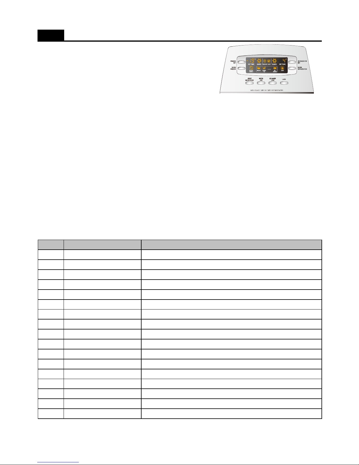
1. How to enter this check mode
1) Press the LOCK button.
2) Press the Super Freezer button 5 times while pushing the Freezer Set button.
2. The Front LED displays the current error code ( if happens ).
; Every time you press the Freezer Set button, the following value display.
1) The appliance running time. ( From the plug in. )
2) Freezer sensor temperature.
3) Defrost sensor temperature.
4) Refrigerator sensor temperature.
5) Room temperature.
6) P Factor display.
7) Filter remaing time until exchange. ( Filter runing time is about 4,320Hr )
3. How to exit this mode
1) Press the LOCK button
FUNCTIONS ( Error Display_Dispenser Models )
2) After 4 minutes automatically exit.
4. Error Code
No
1
2
3
4
5
6
7
8
9
10
11
12
13
14
15
16
17
F3
Return after defrosting : abnormal or defective
Co
Pull-Down mode display (No error)
d2
Forced Defrost mode display (No error)
EA
Drop the ice while Et
Eu
Full ice switch error
C1
Abnormal or defective cycle
EF
Flow sensor is defective.
Et
Horizontal switch error
Eg
Water supply error
dF
Freezer Door switch is defective.
dH
Home Bar Door switch is defective.
El
Ice sensor disconnection or short
rt
Room temperature sensor disconnection or short
d1
Defrost sensor disconnection or short
dr
Refrigerator Door switch is defective.
Display (Error Code) Remark
F1
Freezer sensor disconnection or short
r1
Refrigerator sensor disconnection or short
; All Error Code reset, when the relative parts turn into normal.
17
Page 19
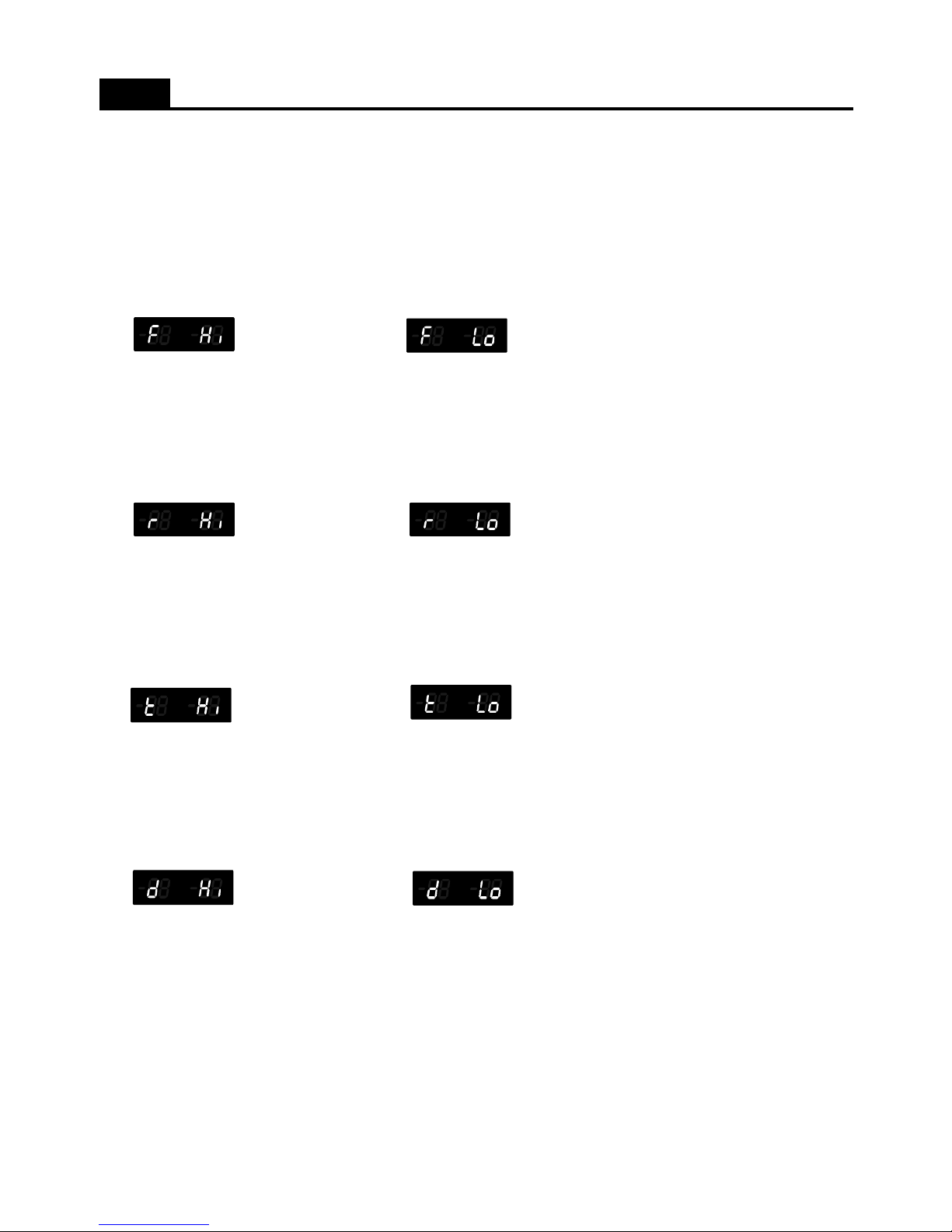
5. Troubleshooting when error happens
( If the relative parts is normal, Error code display will be reset. )
1) F1 error
- Cause : Freezer sensor disconnection or short.
- Check point : Measure the resistance between both terminals after separating CN15 of the Main PCB.
If sensor is disconnected or short, change that in the freezer compartment.
- Error code display
Freezer sensor is short. Freezer sensor is disconneted.
2) R1 error
- Cause : Refrigerator sensor disconnection or short.
- Check point : Measure the resistance between both terminals after separating CN14 of the Main PCB.
If sensor is disconnected or short, change that in the refrigerator compartment.
- Error code display
Refrigerator sensor is short. Refrigerator sensor is disconneted.
FUNCTIONS ( Error Display )
3) rt error
- Cause : Room temperature sensor disconnection or short.
- Check point : Measure the voltage of sensor part on the Main PCB.
If voltage is 0.5~4.5V, normal. If voltage is 0V (short) or 5V (disconnect), change new one.
- Error code display
RT sensor is short. RT sensor is disconneted.
4) d1 error
- Cause : Defrost sensor disconnection or short.
- Check point : Measure the resistance between both terminals after separating CN15 of the Main PCB.
If sensor is disconnected or short, change that on the evaporator.
- Error code display
Defrost sensor is short. Defrost sensor is disconneted.
5) Door switch error ( dr, dF, dH on display )
- Cause : When it senses the door open for more than 1 hour.
- Check point : Check the each door switch and exchange.
6) EI error
- Cause : Ice sensor is abnormal.
- Check point : Measure the resistance between both terminals after separating CN11 of the Main PCB.
If sensor is disconnected or short, change that in the automatic ice maker.
18
Page 20
7) EF error
- Cause : When Flow-sensor abnormal. ( There is no pulse during some time. )
The number of pulse signal is below 10 by 1 second during water supply.
- Check point : Water supply line.
8) Et error
- Cause : Level switch abnormal. ( No pulse is sensed for some time. )
- Control : By time. ( Supply mode is skipped. )
9) Eg error
- Cause : When Ice sensor temperature ( 5 minutes after water supply ) doesn't go up.
- Check point : Ice sensor or water supply line.
10) EA error
- Cause : When sensing ice drop 3 times in level sensor switch error.
- Control : Stop ice maker
FUNCTIONS ( Error Display )
- After 1 time rotation EA error code disappear if level swtich is normal.
11) Eu error
- Cause : Sensor which senses if ice is full or not is abnormal.
- Control : When drops the ice, the motor rotates 90 degree.
12) C1 error
- Cause : When compressor works for over 3 hours although Defrost sensor is over -5C.
- Check point : Refrigerant leakage.
13) F3 error
- Cause : in case defrosting mode ends after 80 minutes.
- Check point : Measure the resistance between both terminals of the defrost heater.
If the resistance is infinity (disconnection) or 0 ohm (short).
19
Page 21
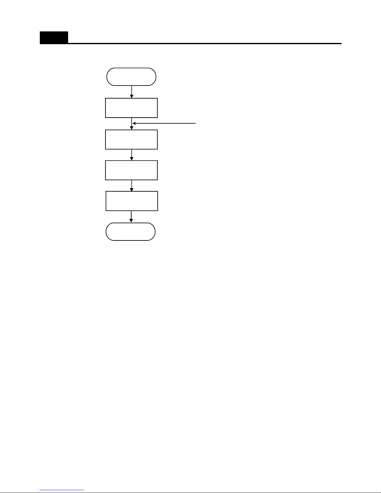
1. Ice making flow
FUNCTIONS ( Ice Maker_ Dispenser Model)
Start
Making the Ice
Ice separating
Water supply
Water supply
check
- water freezing
water supply stand by
- Ice tray rotation to separate ice cubes
- water supply to ice tray
- check if water supply complete or not
1) Press Test switch ( which is under the ice tray ) for more than 1 second and then test starts.
- Test mode starts from ice separating mode.
- In case test switch is abnormal, test is done only 1 time.
2) When the initial power input, ice tray turns to be horizontal.
3) Water supply hose heater control - defrost heater linkage operation
- Heater is always ON if Room temperature sensor is abnormal or room temperature is below 15 degree.
- Heater is ON for 60minutes (max limit time) if Flow sensor is abnormal.
4) Water supply stand by
- Condition : When ice is full
- Operation : Proceeds to ice making mode. ( stop ice separating and water supply mode )
5) Crusher function
- It stops operation when freezer door is open.
- It operates if door is close.
End
20
Page 22
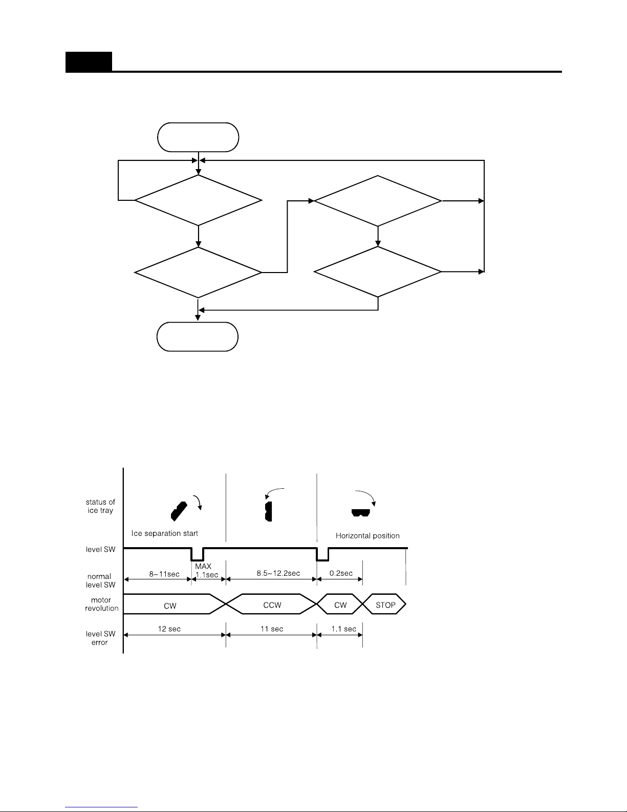
2. Ice making mode
FUNCTIONS ( Ice Maker_ Dispenser Model)
Start
130 minutes pass
Ice sensor is over
-12.5C
Ice separating
Ice sensor is below
-9.5C
15 minutes pass
NO
NO
NO
YES
YES
YES
NO
YES
1) If Ice sensor temperature is below -12.5C after 130minutes, ice making completes.
2) If Ice sensor temperature keep below -9.5C for 15 minutes ice making complete, although the sensor is not below -12.5C
3) After 4.8hours ice making complete, when ice sensor is abnormal,
3. Ice separating(drop) mode
1) Time of each section is to verify level switch error.
2) It senses the rotation in each section.
3) When level switch is error, ice separation controlled by the time.
4) When rotation motor is error, the mode is pause.
21
Page 23
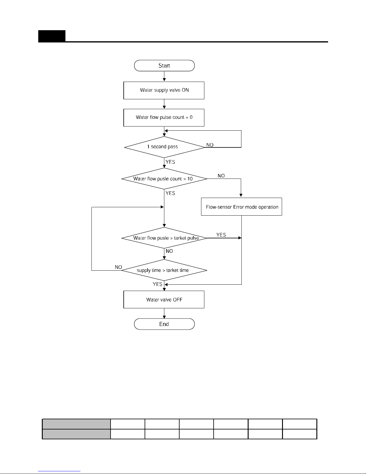
4. Water supply mode
FUNCTIONS ( Ice Maker_ Dispenser Model)
1) If water supply mode starts, the water valve is ON.
2) When Flow sensor is abnormal, supply mode controlled by the time.
3) Factor value is variable when After sales action. ( Adjust water quantity )
- Normal Water flow pulse setting is 238. ( When controlled by the time, maximum time limit is 15 seconds.)
- When the flow sensor is abnormal, time limit is 5.5 seconds.
5. Water supply check mode
Verify water supply completion by comparing room temperature sensor with ice sensor after 5 minutes from water supply.
Room temperature sensor
Below 9C ~ 15C ~ 21C ~ 31C ~ 41C Over 41C
Ice sensor
-10C -9C -8C -7C -6C -5C
22
Page 24
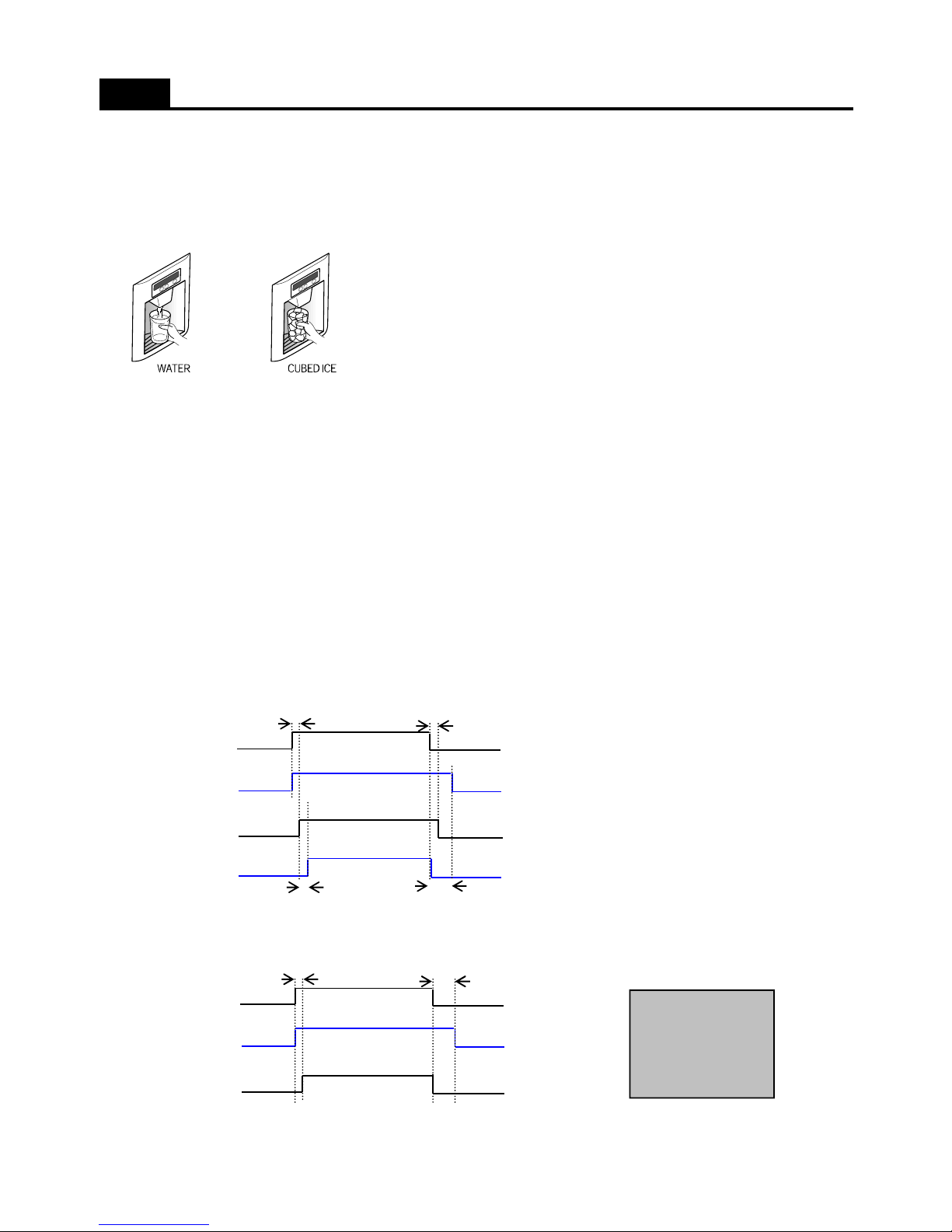
1. Water / Crushed Ice / Cubed Ice Select button
1) Default mode is Water
The selection order is Water - Cubed Ice - Water.
2) In each mode the selected is active by the dispenser button press.
2. Icemaker Lock button : It is active after pushing button
3. Display
1) Water icon turns ON as default mode.
2) The icon of each mode turns ON by pressing its button.
( If display switch makes error during operation of a mode, its icon is OFF.)
FUNCTIONS ( Dispenser Control_Dispenser Model )
3) When Icemaker Lock button is ON, the Lock LED turns ON and Cubed Ice is OFF.
4) When no operation in Cubed / Crushed Ice mode for 1 hour, the mode change into Water mode automatically.
4. Control Flow and Timing Chart
1) Cubed Ice
2) Water Mode
Dispenser
switch
Dispenser
Lamp
Dispenser
Flap
Gear Motor
A
A
B
C
Dispenser
switch
Dispenser
Lamp
A C
Water
Swtich Valve
< Delay Time >
A = 500msec
B = 2.0Sec
C = 5.0Sec
23
Page 25
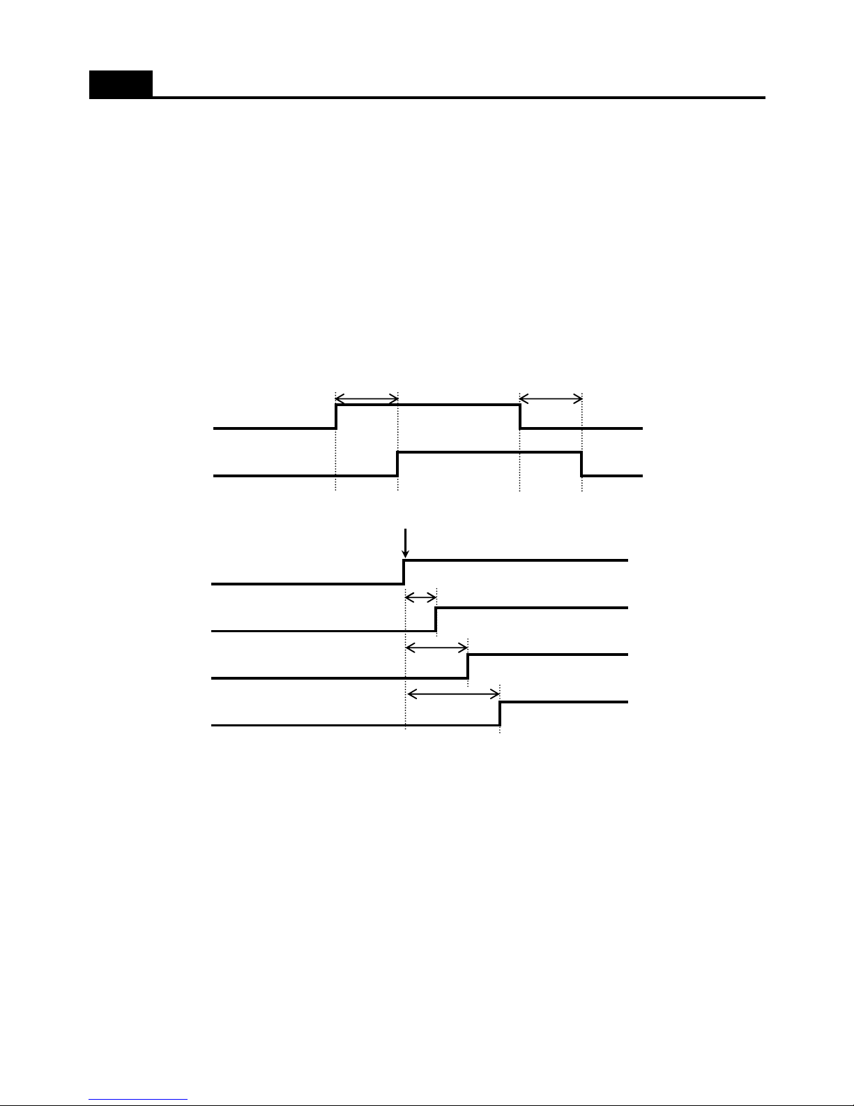
1. Prevention compressor restart function
Although Freezer sensor temperature is low, compressor doesn't restart for 6 minutes from compressor OFF.
2. Beep funtion
1) When pushing the button on the Front Control Pannel.
2) When initail power input. ( 4 beeps after 3 seconds. )
3) When Forced Deforst Mode starts ( 3 beeps ), Pull Down Mode Starts ( 1 beep ).
4) When Door is open. ( Every 1 minute for 5 minutes. )
3. Fan Delay Function
1) Compressor ON/OFF vs Freezer Fan
FUNCTIONS
Compressor
Freezer Fan
60 sec
60 sec
2) Fan priority and delay function
4. Freezer, Refrigerator and Dispenser Lamp Control
1) Refrigerator Lamp
; This lamp operates depending on Refrigerator door switch or Homebar door switch.
; The lamp is automatically off when the switch ( Refrigerator or Homebar ) keeps opened for 10 minutes.
2) Freezer Lamp
; This lamp operates depending on Freezer door switch.
; The lamp is automatically off when the switch ( Freezer compartment ) keeps opened for 10 minutes.
3) Dispenser Lamp ( Dispenser Models Only )
; This lamp operates depending on micro switch which locates dispenser button.
; The lamp keeps ON for 5 seconds after micro swich is close.
Happen
Compressor
Cooling Fan
Feezer Fan
Refrigerator
Fan
0.5 sec
1.0 sec
1.5 sec
24
Page 26
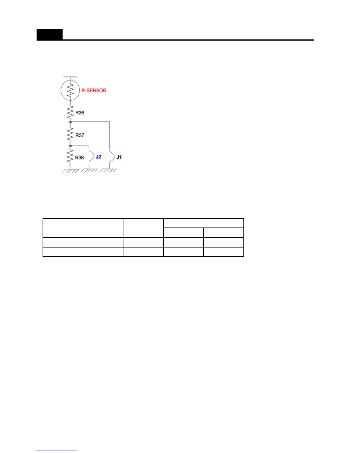
5. Weak Cooling Trouble Shooting
; Adjust refrigerator sensor OFF point
- Normal sensor resistance. (31.4kohm)
- Cut the J18 and increase sensor resistance. (33.4kohm)
FUNCTIONS
- Cut the J18, J19 and increase resistance. (35.4kohm)
J1
-CutCut
--Cut
J2
1.5C down 3.0C down
Normal
Weak Cooling happens
Option
25
Page 27
6. Pull Down Mode
1) How to start
( Inner Basic Model )
; Push the Freezer door switch 5 times while pushing the FRZ. SET button.
( Basic Model )
; Push the SUPER FRZ. 5 times while pushing REF.SET.
( Dispenser Model )
; Push the Lock button. Then Refrigerator Set + Freezer Set + Water/Ice 5 times at the same time.
2) How to control : Compressor, Freezer Fan, Refrigerator Fan and Compressor Cooling Fan is ON for 30 hours.
3) Termination : After 30 hours or power reset.
7. How to check the filter running time. ( Disepnser models only )
1) Press the LOCK button.
2) Press the Super Freezer Button 5 times while pushing the Freezer SET button.
3) Push the Freezer SET button until display Fi-Lt.
4) Remaining time display when push the Dispenser button.
FUNCTIONS
( ex. 40 : 12 means that 4012 minutes remains until exchange. )
8. Adjust the amount of water ( Default setting is P100, 86cc water supply ) - Dispenser Models only
; Function to adjust the amount of water supply.
1) Press the LOCK button.
2) Press the SUPER FRZ. 5 times while pressing the FRZ. SET button.
3) Press the FRZ. SET button until display P100 on LCD.
When need more water supply : Press the SUPER REF button.
- P101 ( 87cc ), P102 ( 88cc ), P103 ( 89cc )……
When need less water supply : Press the REF. SET button.
- P99 ( 85cc ), P98 ( 84cc ), P97 ( 83cc )……
26
Page 28
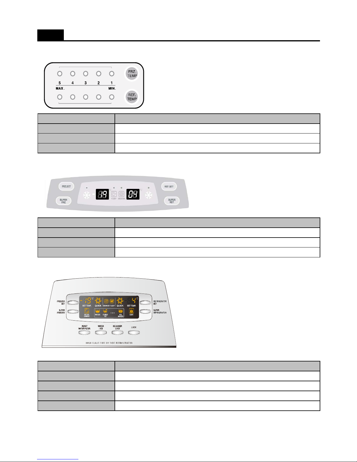
1. Inner Basic Model
2. Basic Model
Error Display
REF. SET + FRZ. SET 5 times
FUNCTIONS ( Summary )
Mode
Forced Defrosting
Pull Down
How to enter
FRZ. SET + REF. SET 5 times
REF. SET + Freezer door switch 5 times
3. Dispenser Model
- All the modes active in LOCK condition except 'Reset Water Filter'. ( Push the LOCK button )
Error Display
FRZ. SET + SUPER FRZ. 5 times
Mode How to enter
Forced Defrosting
FRZ. SET + REF. SET 5 times
Pull Down
REF. SET + SUPER FRZ. 5 times
Mode How to enter
Forced Defrosting
FREEZER SET + REFRIGERATOR SET 5 times
Reset Water Filter
Reset Water Filter button for 5seconds
Pull Down
REFRIGERATOR SET + FREEZER SET + WATER/ICE 5 times
Error Display
FREEZER SET + SUPER FREEZER 5 times
27
Page 29
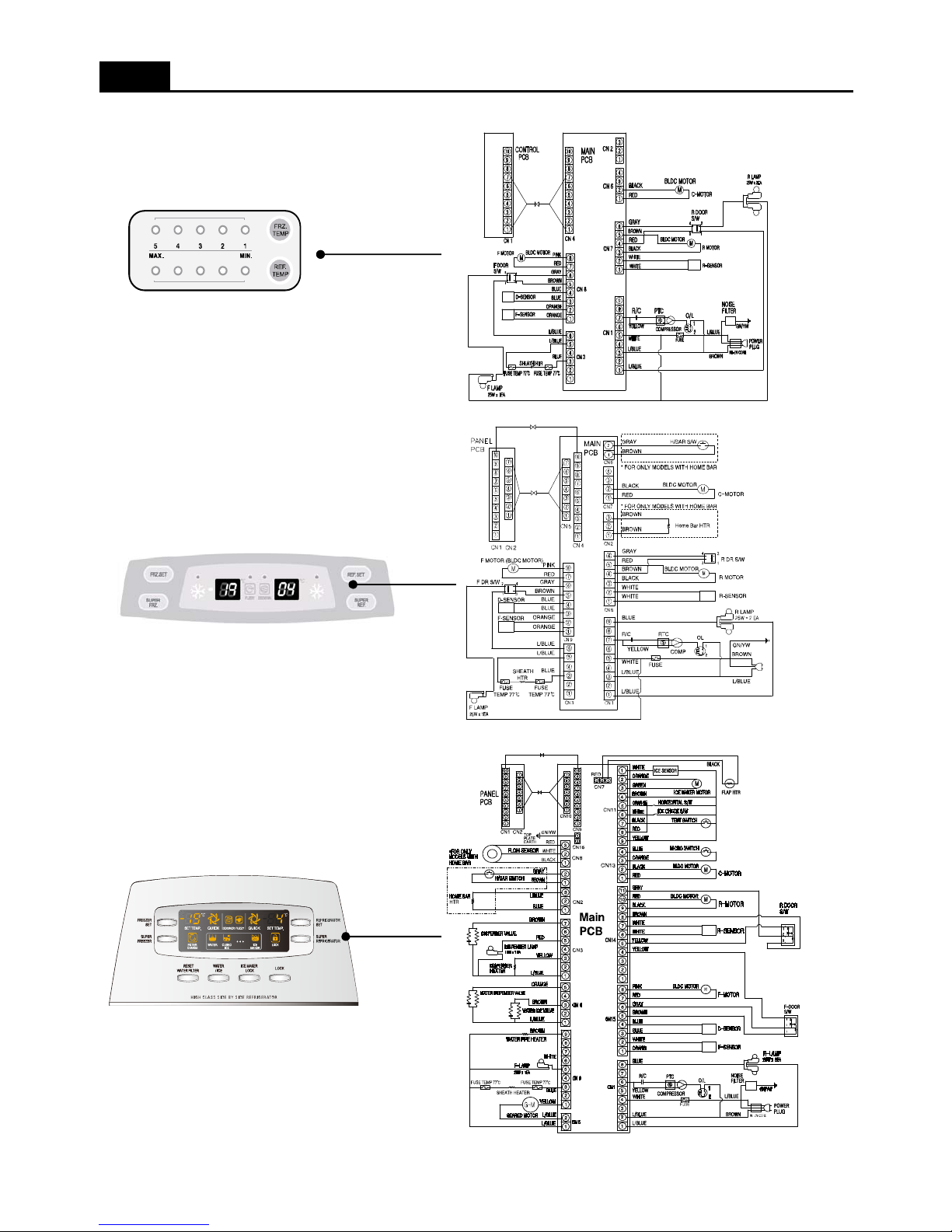
1. Inner Basic Model
2. Basic Model
WIRING DIAGRAM ( Refrigerant : R-134a Type )
3. Dispenser Model
28
Page 30
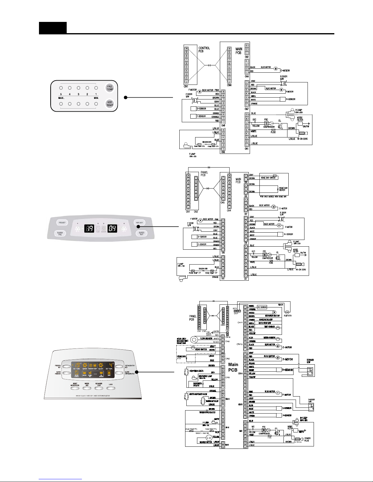
1. Inner Basic Model
2. Basic Model
WIRING DIAGRAM ( Refrigerant : R-600a Type )
3. Dispenser Model
29
Page 31
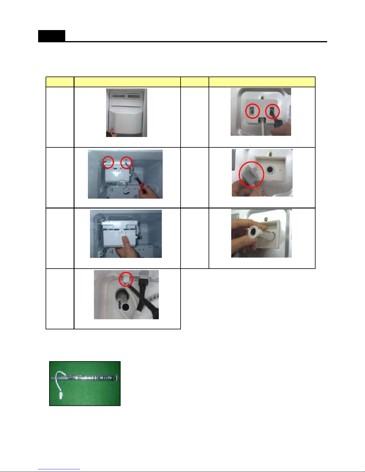
1. Hose Ice maker Tube Assembly. (Dispenser Models Only)
1) Disassembling Procedure
HOW TO CHECK EACH PART
No No
1
Procedure Procedure
26
Remove 2 screws. Disassemble Guide Cab Water Tube A As.
Pull forward Ice Storage Case. Unscrew to remove Cover Guide Cab.
5
2) How to check the Hose Ice Maker Tube As.
; Measure the resistane of two wire.
(Good) : 9680 Ohm (+ - 8%)
( 8900 ~ 10456 ohm )
(If Defective) : exchange the new one.
3
4
7
Pull Hose Ice Maker Tube As.
Remove Water Hose Heater's connector.
Pull Ice Maker
30
Page 32
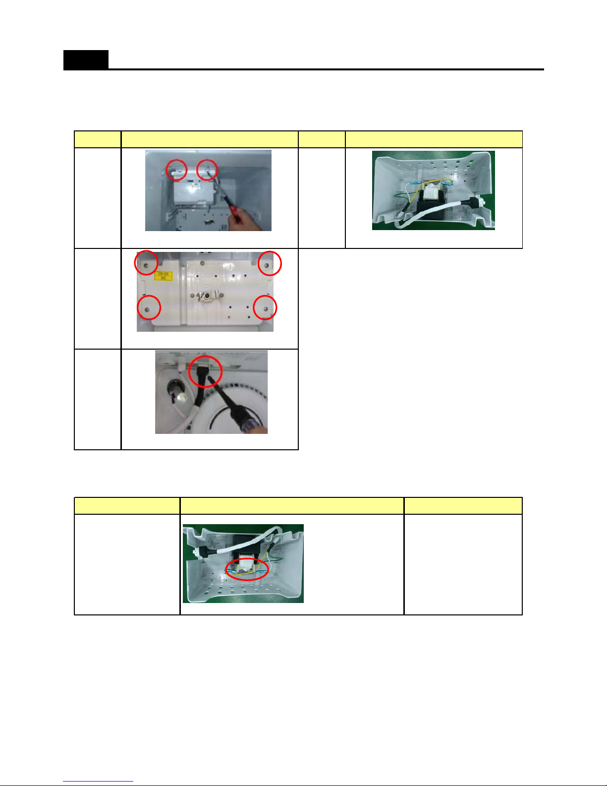
2. Bracket Geared Motor Assembly (Dispenser Models Only)
1) Disassembling Procedure
HOW TO CHECK EACH PART
No No
And unscrew 4 points.
Remove 2 screws. Check solenoid Motor.
14
Procedure Procedure
2
2) How to check the Hose Ice Maker Tube As.
Separate 6 pin connector of Geared Motor.
3
( Good ): 11.3 Ohm (+-10%)
(10.8 ~ 12.7 Ohm)
(Defective): Change the part.
Parts How to Check Remark
Checkthe resistance of
2 terminals with a Tester.
Geared Motor
31
Page 33
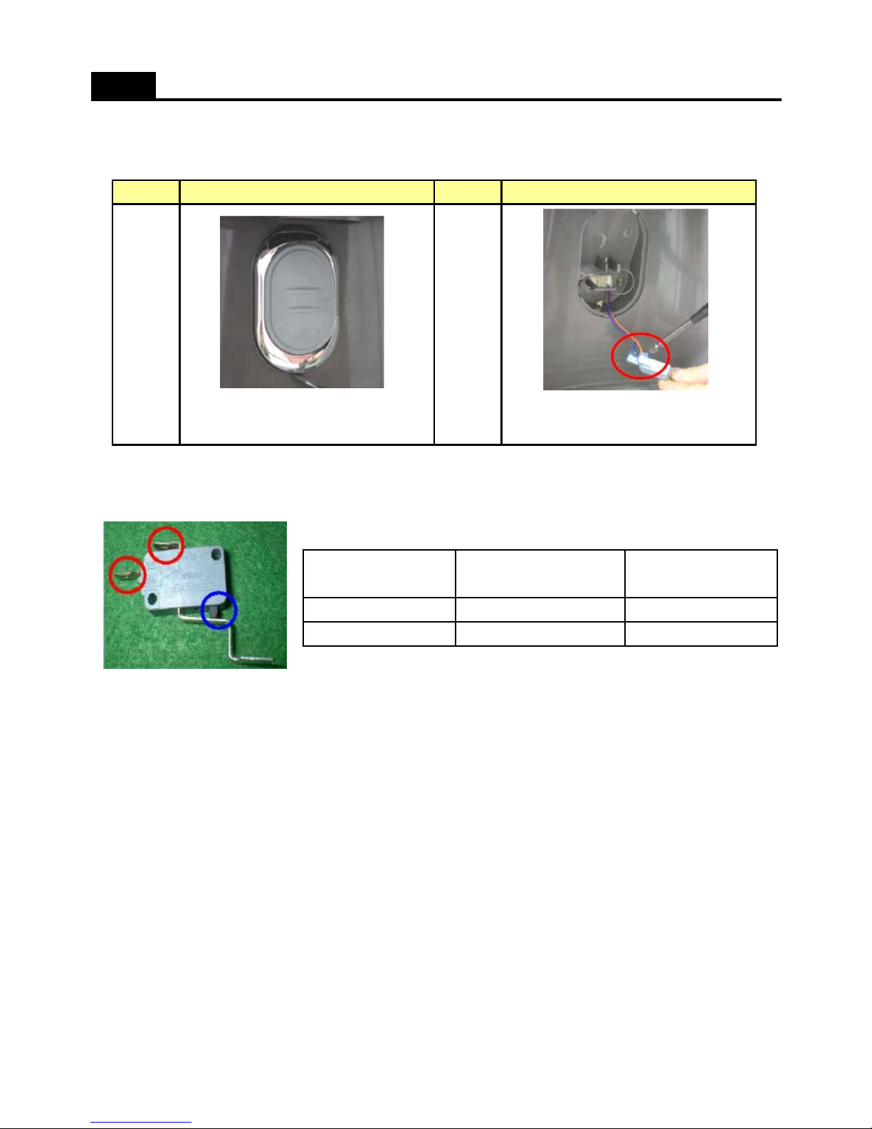
3. Dispenser Micro Switch (Dispenser Models Only)
1) Disassembling Procedure (Features are model dependent)
2) How to check the Hose Ice Maker Tube As.
HOW TO CHECK EACH PART
No No
Dispenser Button and pull up.
1
Pull out the Micro Switch.
( Be careful not to damage the hook. )
Procedure Procedure
2
Insert (-) screw driver into bottom hole of
; Check both terminals (Red circle) with a Multi-Tester.
(Test Mode : Resistance )
; (If defective) Exchage new one.
OFF (Open)
Disconnected No Value
Tact Switch (Blue circle)
Some Value
Test ResultTermainals (Red circle)
ON (Close)
Connected
32
Page 34
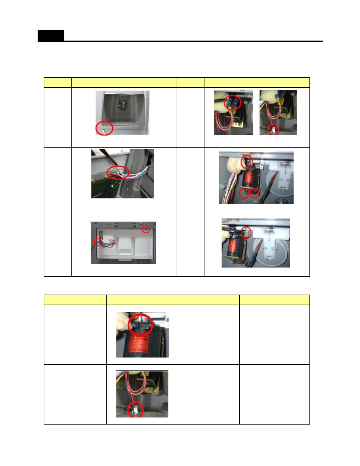
4. Dispenser Solenoid Valve (Dispenser Models Only)
1) Disassembling Procedure (Features are model dependent)
HOW TO CHECK EACH PART
No No
5
4
Procedure
Disassemble the Cover dispenser Box As
2
Procedure
1
Disconnect 2 terminals and 2P Wire.
Separate Front PCB connector.
2) How to check Dispenser Solenoid Valve
36
U
nscrew and remove Soleno
id Val
ve.
(Features are model dependent.)
Unscrew and remove Cover Ice Flap.Unscrew to remove Box Dispenser Ice Shut.
( Good ): 215 Ohm (+-10%)
(193 ~ 236 Ohm)
(Defective): Change the part.
( Good ): 96 Ohm (+-8%)
(88 ~ 104 Ohm)
(Defective): Change the part.
Check the resistance of
both terminals.
Check the resistance of
2 terminals with a Tester.
Flap Heater Assembly
Dispenser Solenoid Valve
Parts How to Check Remark
33
Page 35
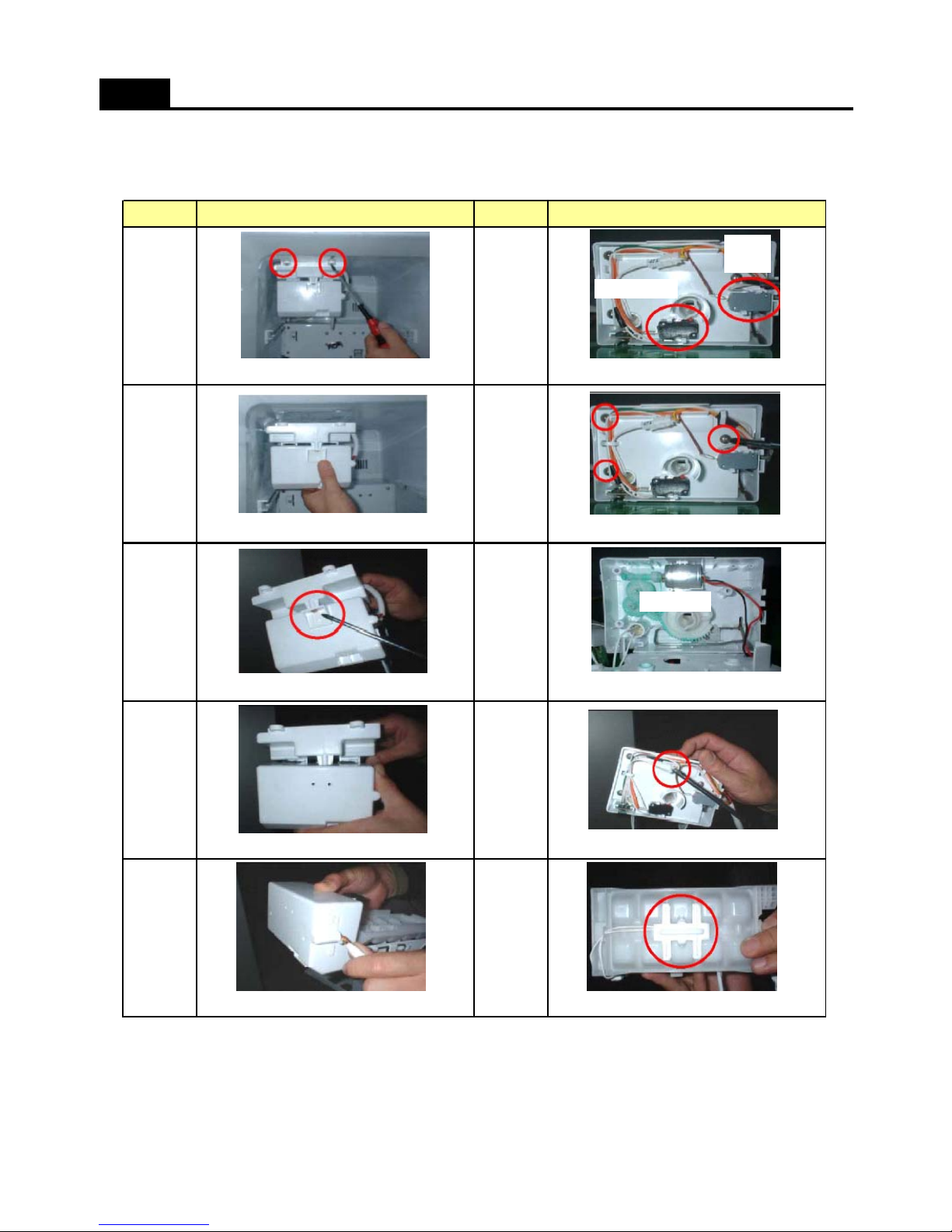
5. Ice Maker (Dispenser Models Only)
1) Disassembling Procedure
HOW TO CHECK EACH PART
No No
Unscrew 3 points.
Remove 2 screws. Remove full ice sensor and level sensor.
27
Pull out the Ice Maker.
16
Procedure Procedure
Level Sensor
Full Ice
Sensor
510
Separate Cover I/M (A) from Cover I/M (B). Remove Ice sensor from Case Icing.
Check if ice droping motor is normal or not.
9
Separate Ice Maker from Frame Ice Maker. Remove 2 Pin housing ( Ice sensor )
Unscrew Fixture of Frame Ice Maker.
3
4
8
Drop Motor
34
Page 36
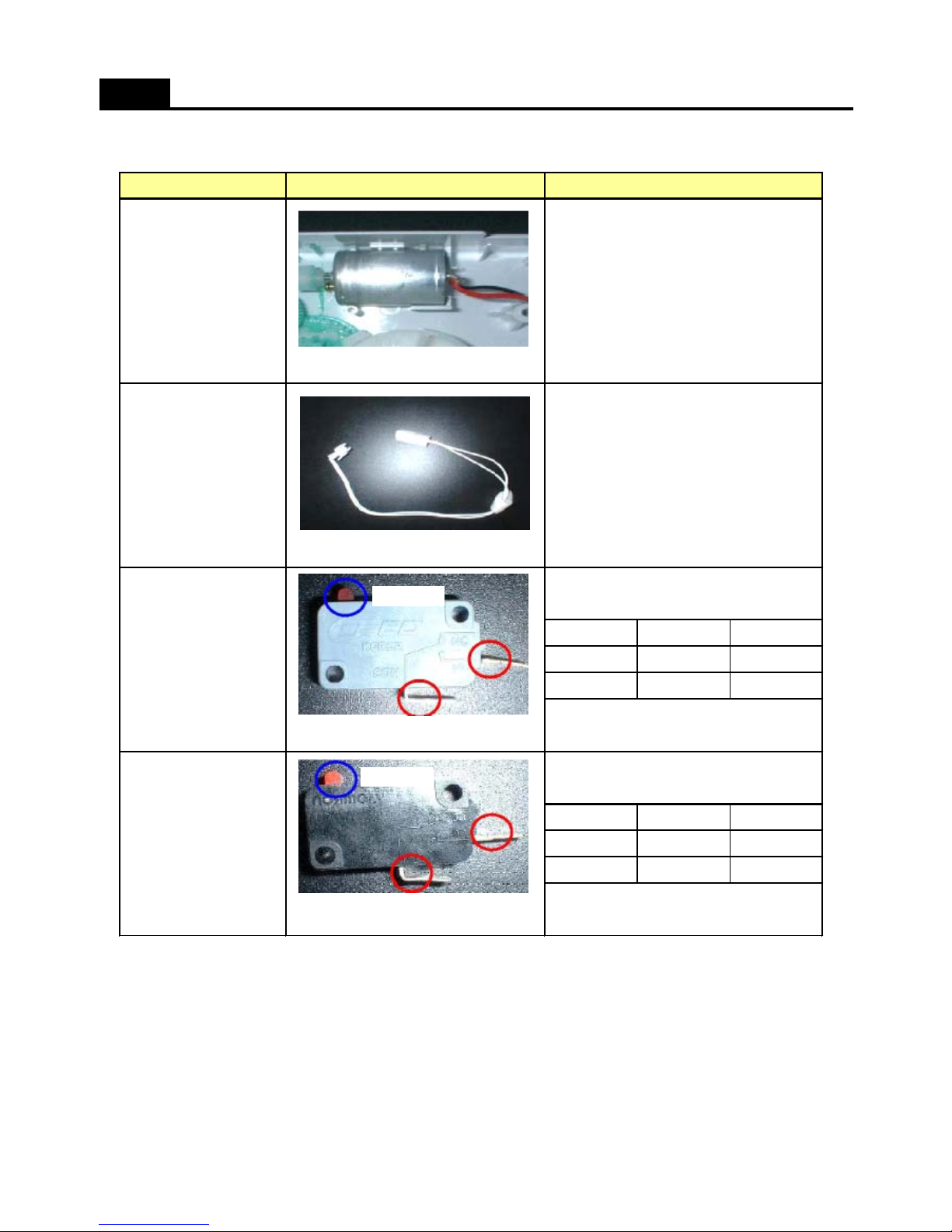
2) How to check Ice Maker
HOW TO CHECK EACH PART
( Good ): 6 ~ 14 ohm
( If defective) : Change the motor
( Good ): 4.4 ~ 50 kohm
; It depends on room temperature.
( If defective) : Change the sensor
RemarkParts How to check
Check resistance between 2 wires.
Ice Drop Motor
Ice Sensor
(Good)
Tact Switch Terminal Result
ON (Close) Connect Some value
OFF (Open) Disconnect No value (0)
( If defective) : Change the Switch
(Good)
Tact Switch Terminal Result
ON (Close) Connect Some value
OFF (Open) Disconnect No value (0)
( If defective) : Change the Switch
Check resistance between 2 wires
.
Check resistance between reds.
Check resistance between reds.
Level Sensor Switch
Full Ice Sensor Switch
Tact Switch
Tact Switch
35
Page 37
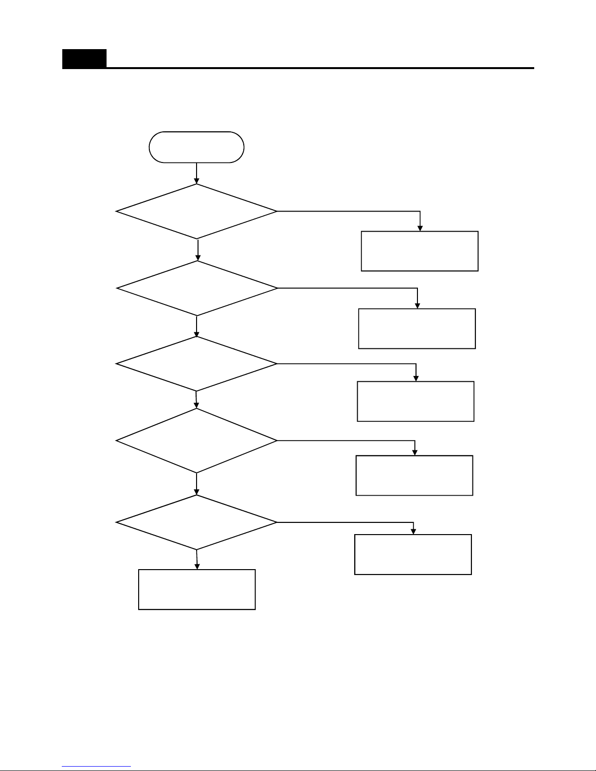
1. Faulty Start ( Lights OFF, Front PCB Power Dead )
TROUBLE SHOOTING
Power plug or fuse
is connected?
Start
Chage the plug or Fuse
1st power of SMPS
is ON?
Check the plug connection
from compressor room and to
CN1 of Main PCB
Yes
No
Yes
No
Main PCB Fuse is
connected?
Voltage value on
Main PCB is OK?
Wire connection of
Front PCB is OK?
Change the fuse
( on the Main PCB )
Change the Main PCB
Chage Front PCB
Checkup and connect
Front PCB wires
No
Yes
No
Yes
No
Yes
36
Page 38
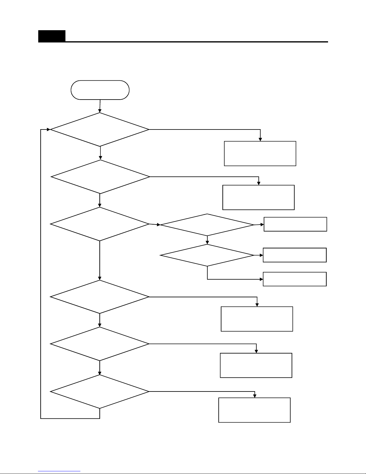
2. Freezing failure ( Weak cooling )
TROUBLE SHOOTING
Error CODE
happens
Start
Refer to Error display
in Funtion page
Does compressor
operate?
Check the Relay wire, OLP
and PTC
No
Yes
Yes
No
Freezer/Compressor
cooling Fan
Temperature Fuse is
OK?
Defrost Heater is
OK?
Change the relative Motor
Change the Fuse
( Left up side of Evaporator )
Change the Defrost Heater
( 250W )
No
Yes
No
Yes
No
Yes
Fan Motor
Wire is connected?
Change Main PCB
Check lead wire
No
Yes
Yes
No
Ice formation on
Evaporator?
Check ice formation and if
refrigerant leak is found, repair
No
37
Page 39
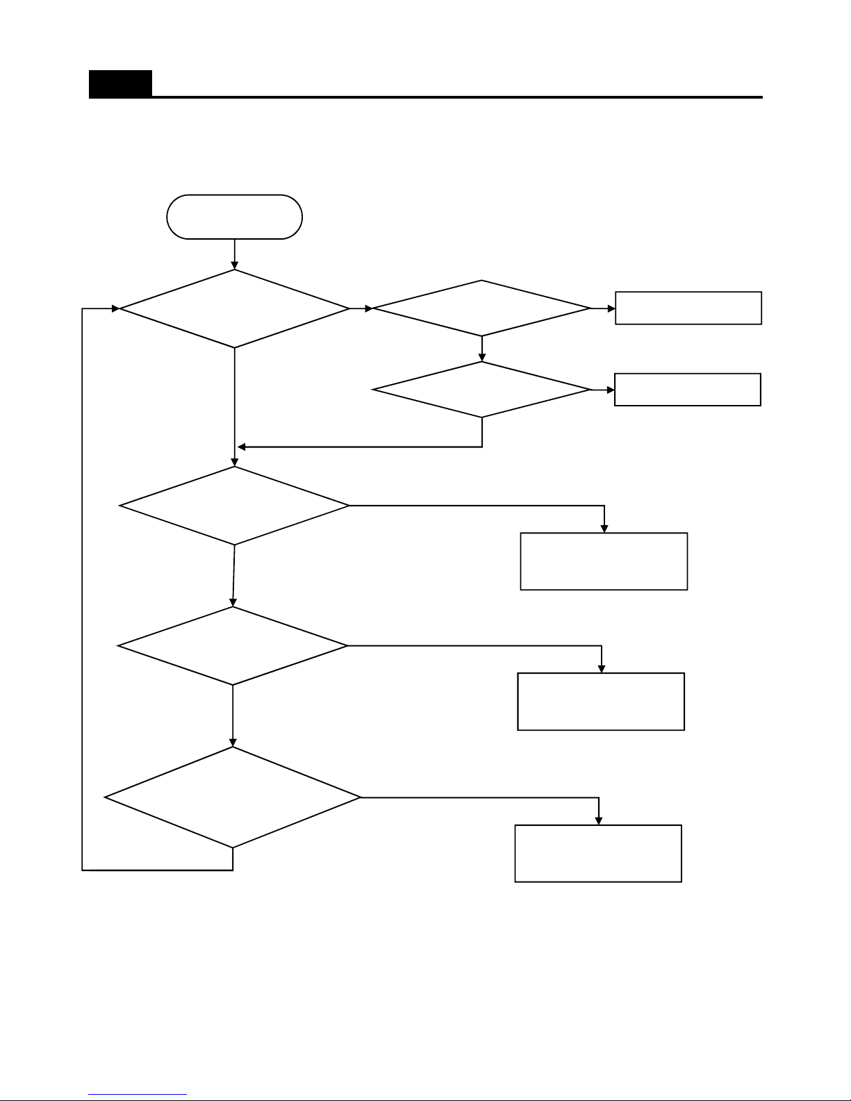
3. Ice formation on Freezer Louver
TROUBLE SHOOTING
Dews form on the
gasket surface
Start
Remove the gap
No
Yes
No
Gasket has a gap
Door hang down?
Reassemble the door
Yes
Yes
No
Door opening is too
frquently?
Heat appliance are
too close?
Watery or hot foods
are stored in
refrigerator
Wipe out dews on the louver
surface and run again
No
No
No
Make enough distance
between heat appliance and
refrigerator
Explain not to open too
frequently
Yes
Yes
Yes
38
Page 40
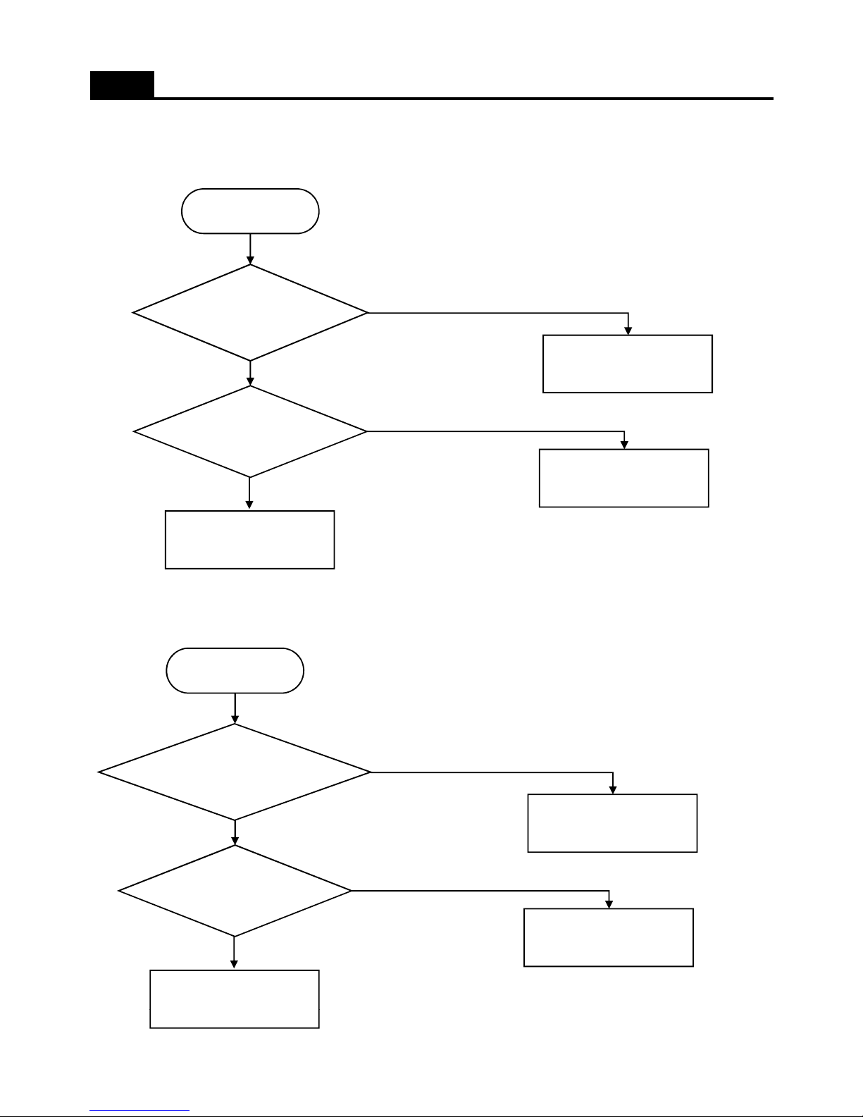
4. Disconnection / Breaking of Interior Lights Wire
4-1. Freezer Door
TROUBLE SHOOTING
Freezer light filament
is disconnected or
breaking?
Start
Change the light bulb
Connection of
Freezer door switch
Repair Door Switch
No
Yes
Yes
No
4-2. Refrigeraotor Door
Check the Door Switch
connection and light socket
Refrigerator light
filament is disconnected
or breaking?
Start
Change the light bulb
Connection of
refrigerator door
Repair Door Switch
No
Yes
Yes
No
Check the Door Switch
connection and light socket
39
Page 41
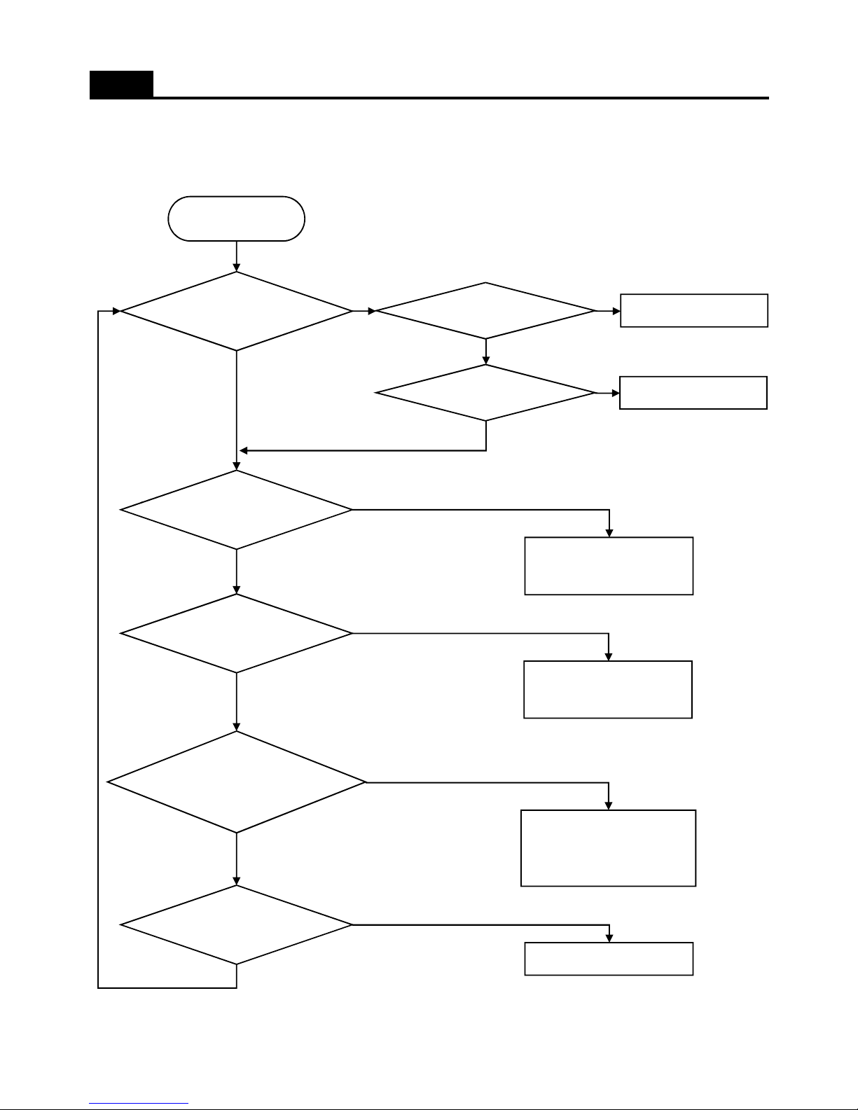
6. Dews on Refrigerator Compartment
TROUBLE SHOOTING
Dews form on the
gasket surface
Start
Remove the gap
No
Yes
No
Gasket has a gap
Door hang down?
Reassemble the door
Yes
Yes
No
Door opening is too
frquently?
Heat appliance are
too close?
Watery or hot foods
are stored in
refrigerator
Advise to cool down foods
enough, wrap or cover foods
with much water before storing
in the compartment
No
No
No
Make enough distance
between heat appliance and
refrigerator
Explain not to open too
frequently
Yes
Yes
Yes
Fan operation is ok?
Repair and change the Motor
No
Yes
40
Page 42
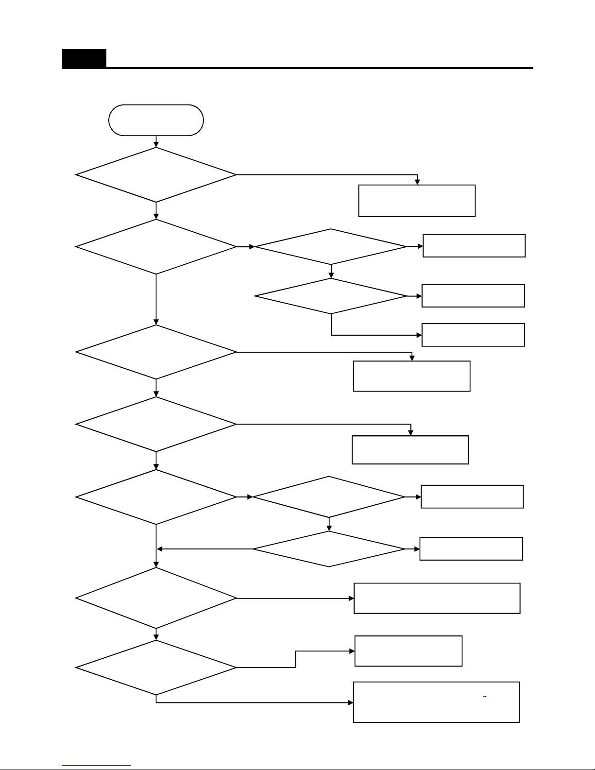
5. Refrigeration failure ( Foods does not get cool or cold soon )
TROUBLE SHOOTING
Error CODE
happens
Start
Refer to Error display
in Funtion page
Refirgerator motor
operates?
Change the relative Motor
Yes
No
No
Yes
Fan Motor
Wire is connected?
Change Main PCB
Check lead wire
No
Yes
Yes
No
Refrigerator sensor
is normal?
Freezer
compartment is OK?
Check the sensor and
connector
Refer to 'Freezing Failure'
page
No
Yes
No
Yes
Refrigerator gasket
has gap?
Remove the gap of gasket
No
Gasket has any
Door hang down?
Reassmeble door
Yes
No
Yes
Yes
Foods places just
close to Refrigerator
Refrigerator door
opens too often?
No
No
No
Explain not to place foods close to sensor
or cold air spout
Yes
Explain not to open door too
frequently
-
Counse
l to
use
'Max' dial setting.
Cou se o use a d a se g
- Cut the jump wire on the Main PCB
Refer 'FUNCTION (etc)' page.
No
41
Page 43
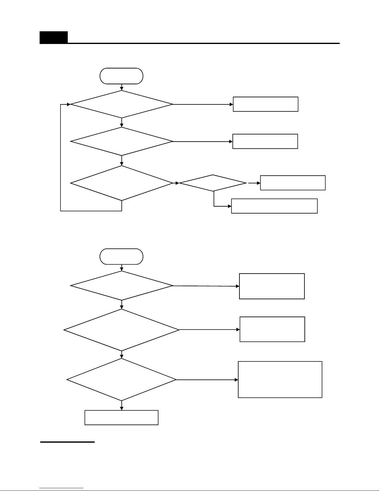
7. Cold of Vegetable Case
TROUBLE SHOOTING
Temperature setting
Start
Check Valve
Any Refrigerator
sensor Error?
Change to 'MIDDLE' mdoe
No
Yes
Yes
Repair or change the new
No
Repair or change the new
Sensor is ok?
Check sensor connection
(Check the connector to Main PCB)
No
No
Yes
Yes
8. Operation Noise of Refrigerator
8-1. Compressor operation noise
Remark
Refrigerator Foot
level is ok?
Start
Rubber absorber to
hold compressor is
distorted or aged?
Sound from
compressor itself or
vibration?
Adjust foot leveling
(Refer to User Manual)
Yes
No
No
Change the Rubber
absorber
Yes
Yes
Attach a restrainer on the
compressor head to reduce
vibration and high frequency noise
No
Change the compressor
- Compressor sound is somewhat normal because it works like a heart to circulate the refrigerant in the pipes.
- Rattling or metalic touch sound of motor, piston of compressor can be heard when it starts or stops.
42
Page 44
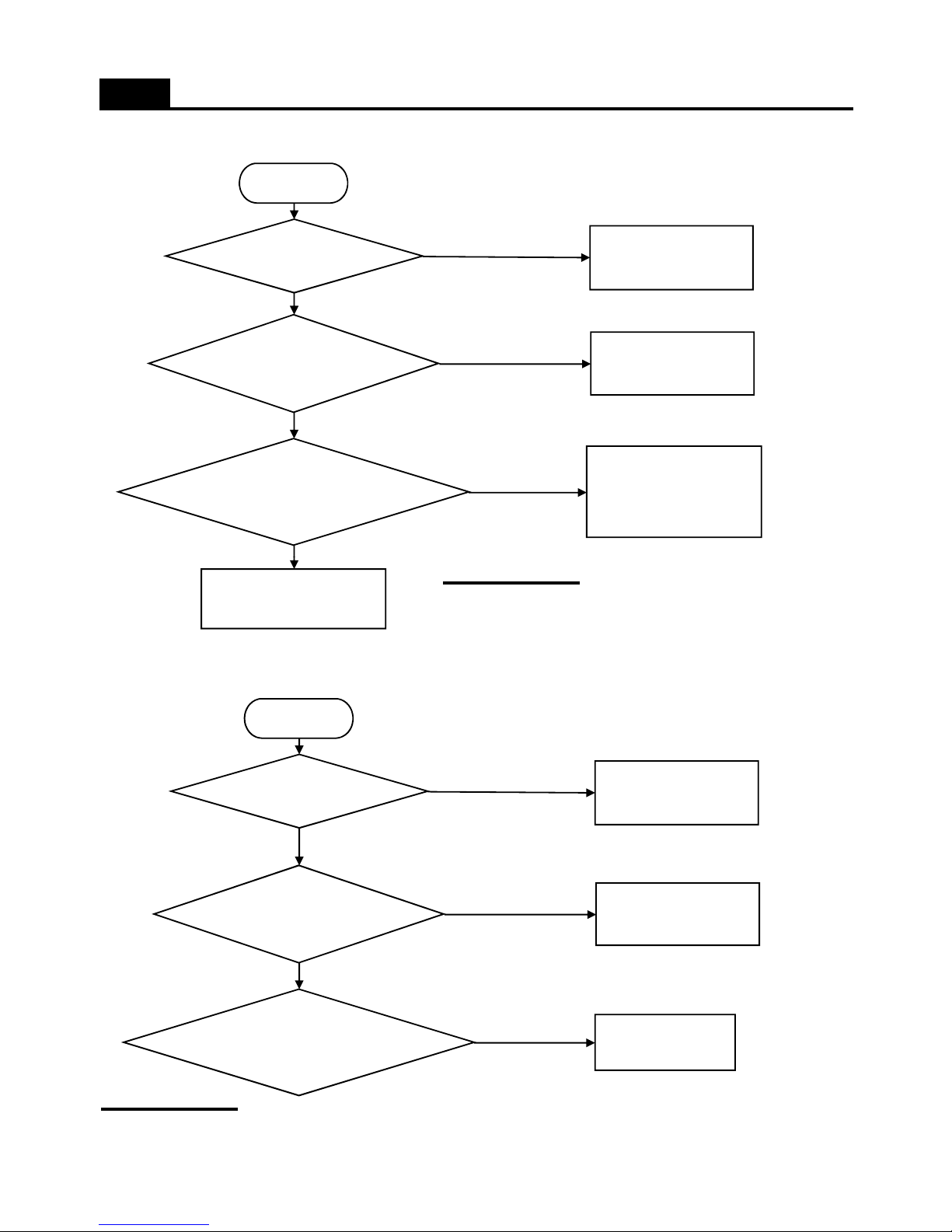
8-2. Refrigerant Flow Sound
TROUBLE SHOOTING
Water flowing or
hiss sounds?
Start
Hiss or sizzling sound
when comprssor starts
Any shaking sound from
Freezer compartment when
compressor works?
Attach an absorber gum
on the capillary tube
No
No
Yes
Apply a gum on the
accumulator
Yes
Fasten the evaporator tightly
not to touch liner surfaces.
Yes
8-3. Fan Noise
Remarks
Remarks
No
Explain refrigerator work
mechanism and sound to the
user or customer
- Water flowing sound, hiss or sizzling sound can make while
refrigerant in the pipes is changing from liquid to gas state when
compressor starts or stops.
- It is normal sound.
Fan is touching the
something?
Start
Fan Motor assembly is
moving or shaking?
Motor has its own noise or
vibration when working?
Damaged / transformed?
Set it right not to touch
No
No
Yes
Set it right not to move
Yes
Chenage the new
Yes
- The fan is sending out cold air to circulate each corner of the compartsment.
- When the air is touching the surface of louver or liner wall, such sound can make.
43
Page 45
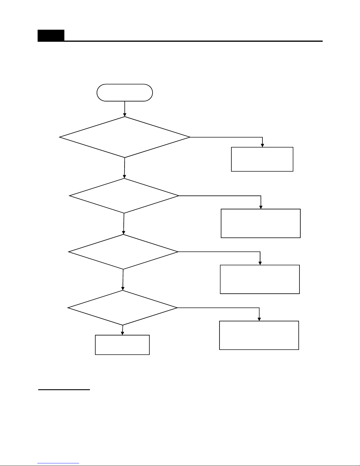
8-4. Pipe Noise
TROUBLE SHOOTING
Pipes are touching in the
machine (compressor)
compartment?
Start
Separate the touching
pipes, if any..
Yes
Tray drip makes noise
by condenser shaking?
Yes
No
- Refrigerant is erupting rapidly from the compressor to circulate pipes, so pipe shaking noise can make to some degree.
- In case compressor vibration is sent to a pipe directly, apply vibration absorber rubbers to welding pionts of pipepe and
comprssor or to a much bent piont on the pipe.
Remarks
Apply cushion matterial between
compressor base and tray drip.
Pipe itself is shaking
much?
Move or change the points of
vibration absorber rubbers on the
pipes to reduce the shaking
No
Yes
Compressor itself is
shaking much?
Attach a absorber on the
compressor head
No
Yes
Explain to the User
No
44
Page 46
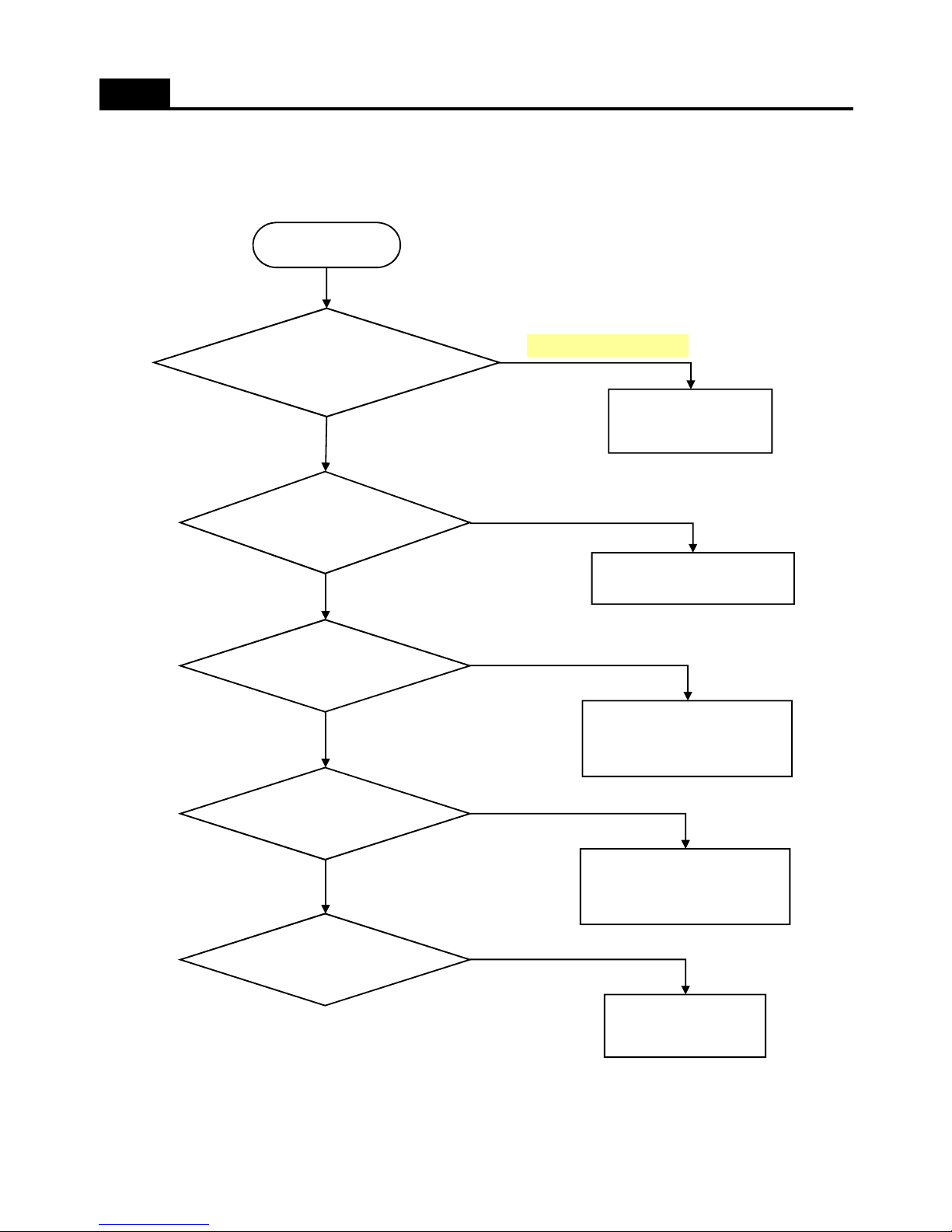
9. Door opening alarm continues after closing
TROUBLE SHOOTING
Door switch pushing well?
Start
Attach a thin pad on the
door liner or change the
door assmbly.
No
Door switch is soaked
with water or there is
water in the switch?
Yes
Yes
Check if interior light is ON
Change the door switch
PCB input is OK?
Repair any disconnection of wires
and defective door switch
No
Yes
Connector insertion to
Main PCB is OK?
Repair the defective connection
No
Yes
No
Door switch itself is ok?
Change the new
Yes
45
Page 47
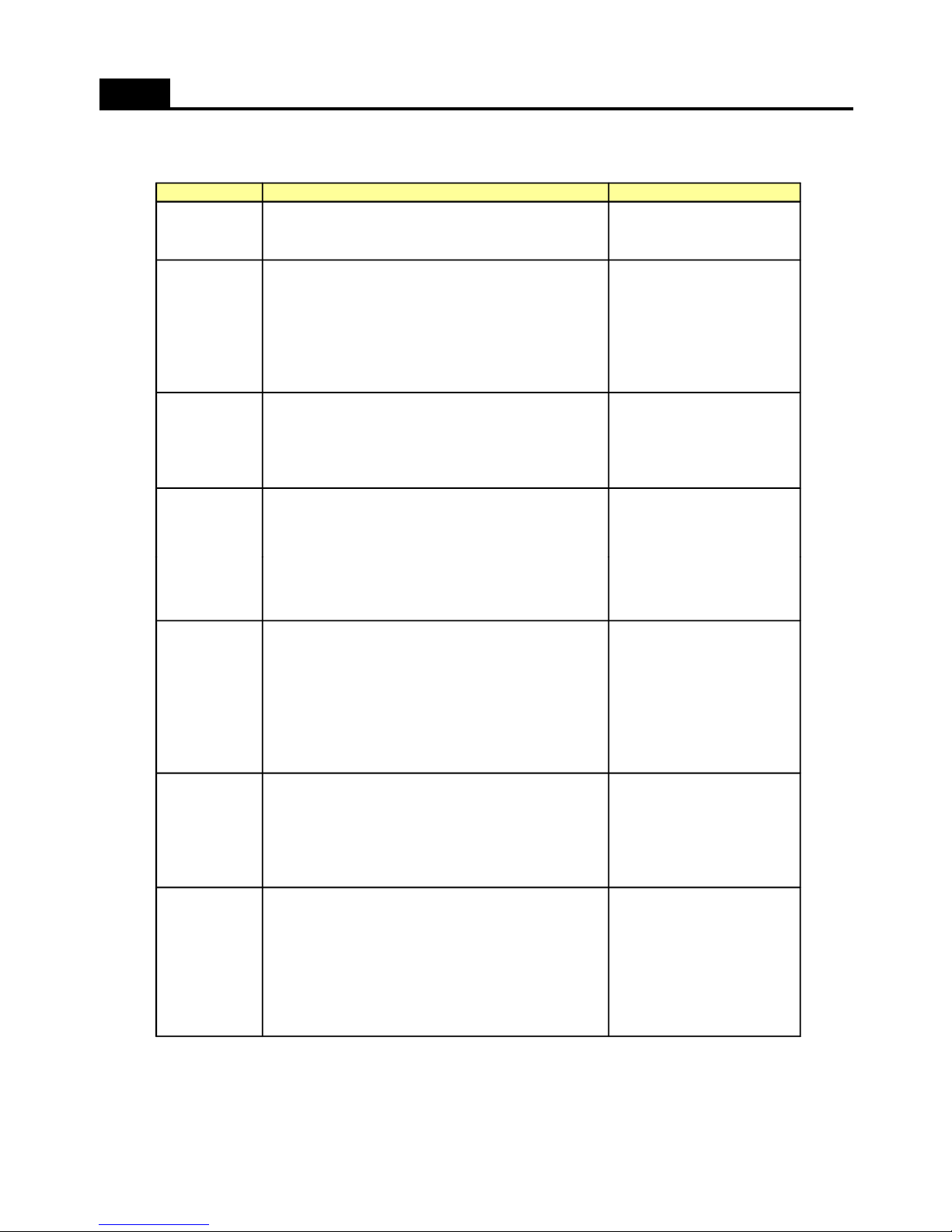
1. Summary of Heavy Repair
COOLING CYCLE HEAVY REPAIR
Bombe (mass cylinder),
refrigerant manifold gauge,
Weigh and control the bombe in a vacuum conditions
with electronic scales and charge through compressor
Refrigerant
charging and
Vacuum pump
, Manifold gauge.
Evacuate for more than forty minutes after connecting
manifold gauge hose and vacuum pump to high (drier)
and low (compressor) pressure sides.
Vacuum
Pipe Cutter, Gas welder,
N2 gas
Confirm refrigerant (R-134a or R-600a) and oil for
compressor and drier.
Confirm N2 sealing and packing conditions before use.
Use good one for welding and assembly.
Weld under nitrogen gas atmosphere.
Repair in a clean and dry place.
Parts
replacement
and welding
Nipper, side cutters
Cut charging pipe ends (Comp. & Dryer) and
discharge refrigerant from drier and compressor.
Remove
refrigerant
Residuals
ToolsContentsProcess
Installation should be conducted in accordance with
the standard installation procedure. (Leave space of
more than 5 cm from the wall for compressor
compartment cooling fan mounted model.)
Transportation
and
installation
Copper brush, Rag, Tool box
Remove flux from the silver weld joints with soft
brusher wet rag. (Flux may be the cause of corrosion
and leaks.)
Clean tools and store them in a clean tool box
or in their place.
Compressor
compartment
and tools
arrangement
Electronic Leak Detector,
Driver.
Check leak at weld joints.
Note :Do not use soapy water for check.
Check cooling capacity
- Check condenser manually to see if warm.
- Check hot pipe manually to see if warm.
- Check frost formation on the whole surface of the
evaporator.
Check
refrigerant leak
and cooling
capacity
e
l
ectronic scales, punching
off flier, gas welding machine
inlet (Process tube)
.
Charge while refrigerator operates).
Weld carefully after inlet pinching.
charging
inlet welding
46
Page 48
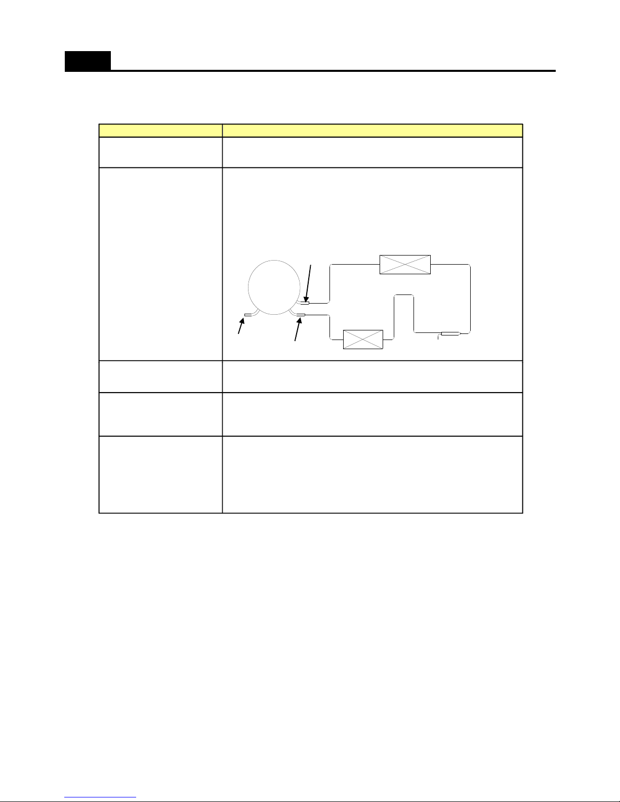
2. Precautions During Heavy Repair
COOLING CYCLE HEAVY REPAIR
1) Remove retained refrigerant more than 5 minutes after turning off
a refrigerator. (If not, oil will leak inside.)
2) Remove retained refrigerant by cutting first high pressure side
(drier part) with a nipper and then cut low pressure side.
(If the order is not observed, oil leak will happen.)
Removal of retained
refrigerant.
- Use special parts and tools for R-134a or R-600a.
Use of tools.
PrecautionsItems
Process
Compresso
Evaporato
Drye
High Pressure
Low
pressure
Suction
Discharge tube
Condense
Hot
1) Nitrogen only should be used when cleaning inside of cycle pipes
inside and sealing.
2) Check leakage with an electronic leakage tester.
3) Be sure to use a pipe cutter when cutting pipes.
4) Be careful not the water let intrude into the inside of the cycle.
Others.
- Weld under nitrogen atmosphere in order to prevent oxidation
inside a pipe. (Nitrogen pressure : 0.1~0.2 kg/cm2.)
Nitrogen blowing
welding.
- Be sure to replace drier when repairing pipes
and injecting refrigerant.
Replacement of drier.
47
Page 49
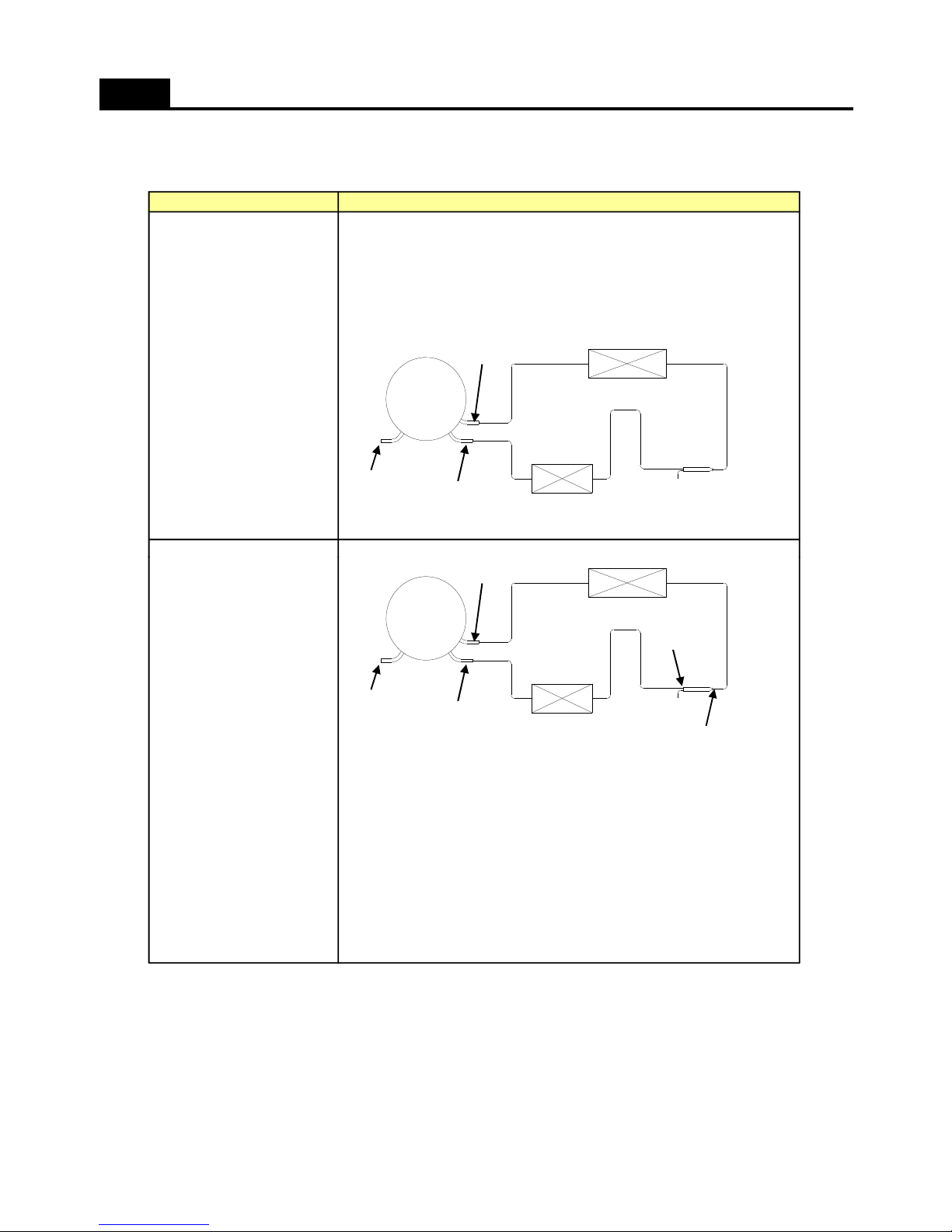
3. Practical Work for Heavy Repair
COOLING CYCLE HEAVY REPAIR
1) Remove residual refrigerant more than 5 minutes later after
turning off the refrigerator. ( If not, compressor oil may leak inside.)
2) Remove retained refrigerant slowly by cutting first high pressure
side (drier part) with a nipper and then cut low pressure side.
1. Removal of residual
refrigerant.
PrecautionsItems
Process
Compresso
Evaporato
Drye
High Pressure
Low
pressure
Suction
Discharge tube
Condense
Hot
* When replacing a drier:
Weld 1 and 2 parts by blowing nitrogen (0.1~0.2kg/cm2) to high
pressure side after assembling a drier.
* When replacing a compressor:
Weld 3 and 4 parts by blowing nitrogen to the low pressure side.
Note) For other parts, nitrogen blowing is not necessary because it
does not produce oxidized scales inside pipe because of its short
welding time.
2. Nitrogen blowing
welding.
- KEYPOINTING
Welding without nitrogen blowing produces oxidized scales inside
a pipe, Which affect on performance and reliability of a product.
Process
Compresso
Evaporato
Drye
High Pressure
Low
pressure
③
Condense
④
①
②
Hot
48
Page 50
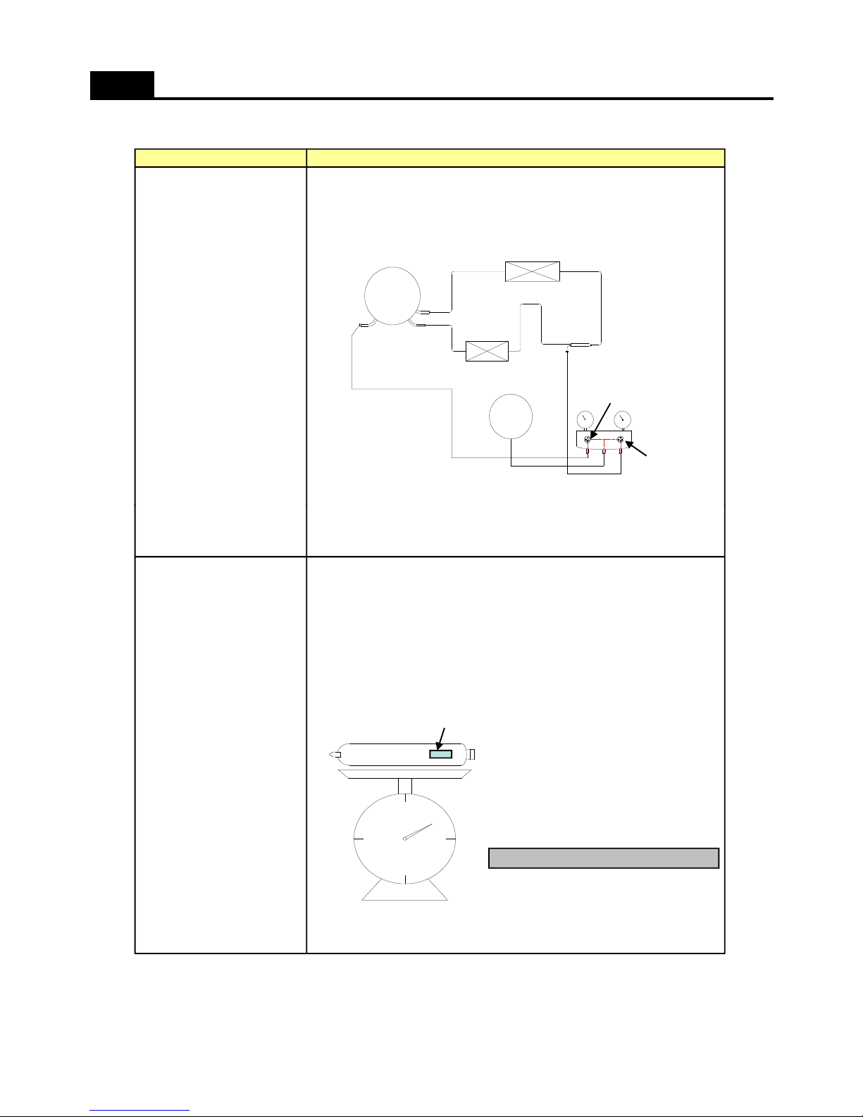
COOLING CYCLE HEAVY REPAIR
* Pipe Connection
Connect a red hose to the high pressure side and a blue hose
to the low pressure side.
* Vacuum Sequence
Open 1,2 valves and evacuate for 40 minutes.
Close valve 1.
3.Vacuum degassing
PrecautionsItems
Compresso
Evaporato
DryeCondense
Vaccu
m
Hot
Blu
Yello
Re
High
Pressur
Low
Pressur
①
②
KEYPOINTING
1) If power is applied during vacuum degassing, vacuum degassing
* Charging sequence
1) Check the amount of refrigerant supplied to each model after
completing vacuum degassing.
2) Evacuate bombe with a vacuum pump.
3) Measure the amount of refrigerant charged.
- Measure the weight of an evacuated bombe with an electronic scale.
- Charge refrigerant into a bombe and measure the weight. Calculate
the weight of refrigerant charged into the bombe by subtracting the
weight of an evacuated bombe.
4.Refrigerant charging
shall be more effective.
2) Operate compressor while charging refrigerant. (It is easier and
more certain to do like this.)
the amount of refrigerant charged
= a weight after charging
- a weight before charging
(a weight of an evacuated cylinder)
Calculation of amount of refrigerant
- KEYPOINTING
1) Be sure to charge
the refrigerant at
around 25C.
2) Be sure to keep
-5g in the winter
and +5g in summer.
Indicate the weight
of
49
Page 51
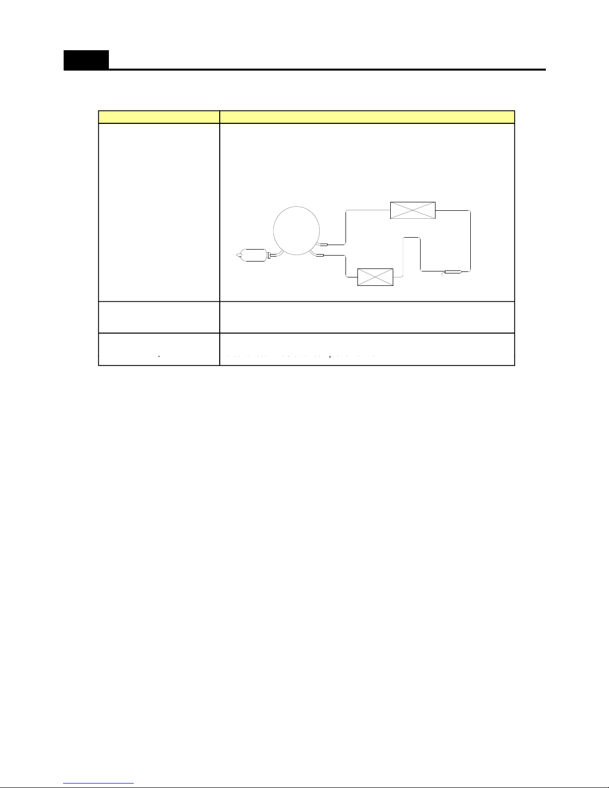
COOLING CYCLE HEAVY REPAIR
PrecautionsItem
4) Refrigerant Charging
Charge refrigerant while operating a compressor as shown above.
5) Pinch a charging pipe with a pinch-off plier after completion of charging.
6) Braze the end of a pinched charging pipe with copper brazer and take
a gas leakage test on the welded parts.
4.Refrigerant charging
Hot
* Take a leakage test on the welded or suspicious area with an
electronic leakage tester.
5. Gas-leakage test
* Check each pipe is placed in its original place before closing
-
6. Pipe arrangement
in each cycle
< Standard Regulations for Heavy Repair >
a cover back
M/C after completion of work.
y
1) Observe the safety precautions for gas handling.
2) Use JIG (or wet towel) in order to prevent electric wires from burning during welding.
(In order to prevent insulation break and accident.)
3) The inner case shall be melted and insulation material (polyurethane) shall be burnt
if not cared during welding inner case parts.
4) The copper pipe shall be oxidized by overheating if not cared during welding.
5) Not allow the aluminum pipes to contact to copper pipes. (In order to prevent corrosion.)
6) Make sure that the inner diameter should not be distorted while cutting a capillary tube.
7) Be sure that a suction pipe and a filling tube should not be substituted each other during welding.
( High efficiency pump.)
50
Page 52
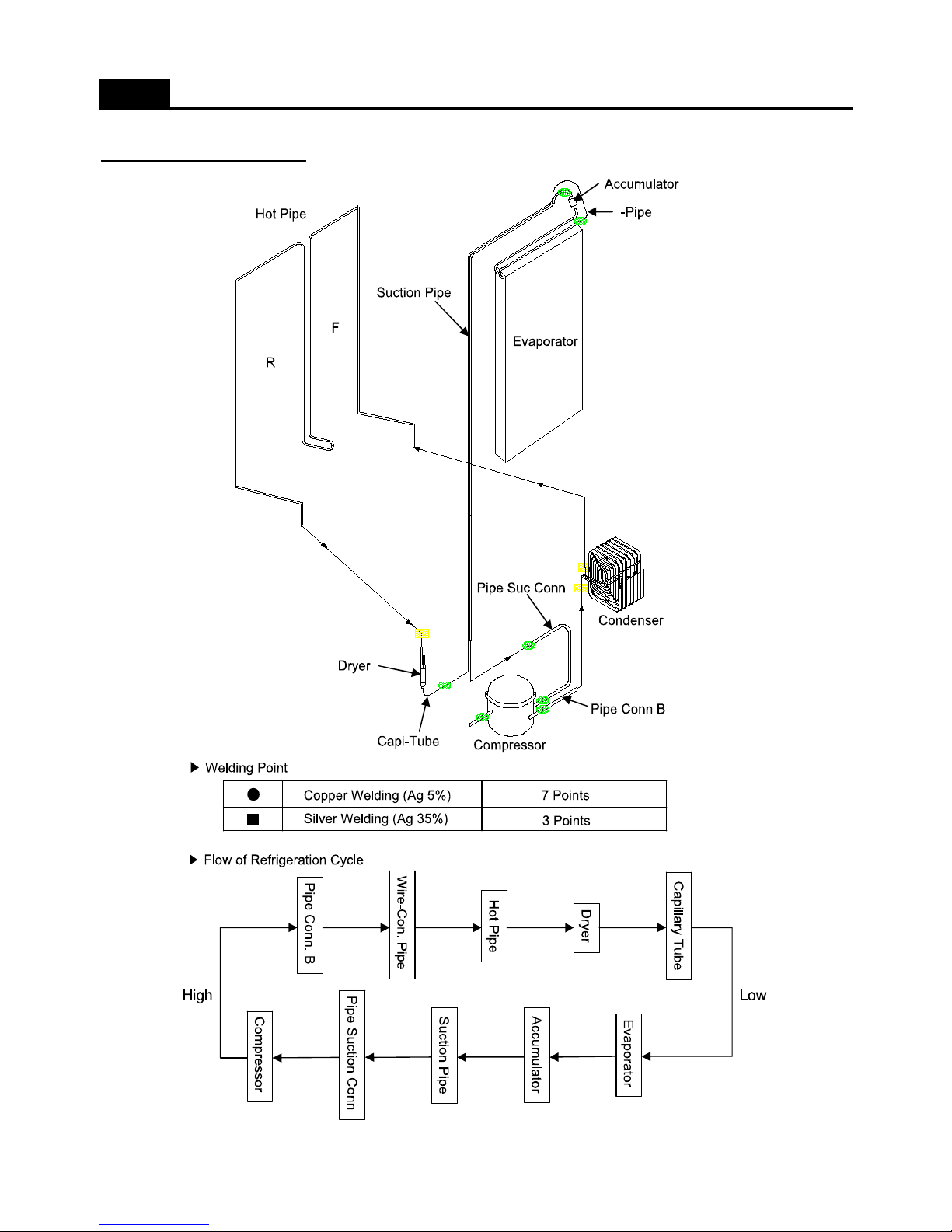
COOLING CYCLE HEAVY REPAIR
Brzing Reference Drawings
51
Page 53
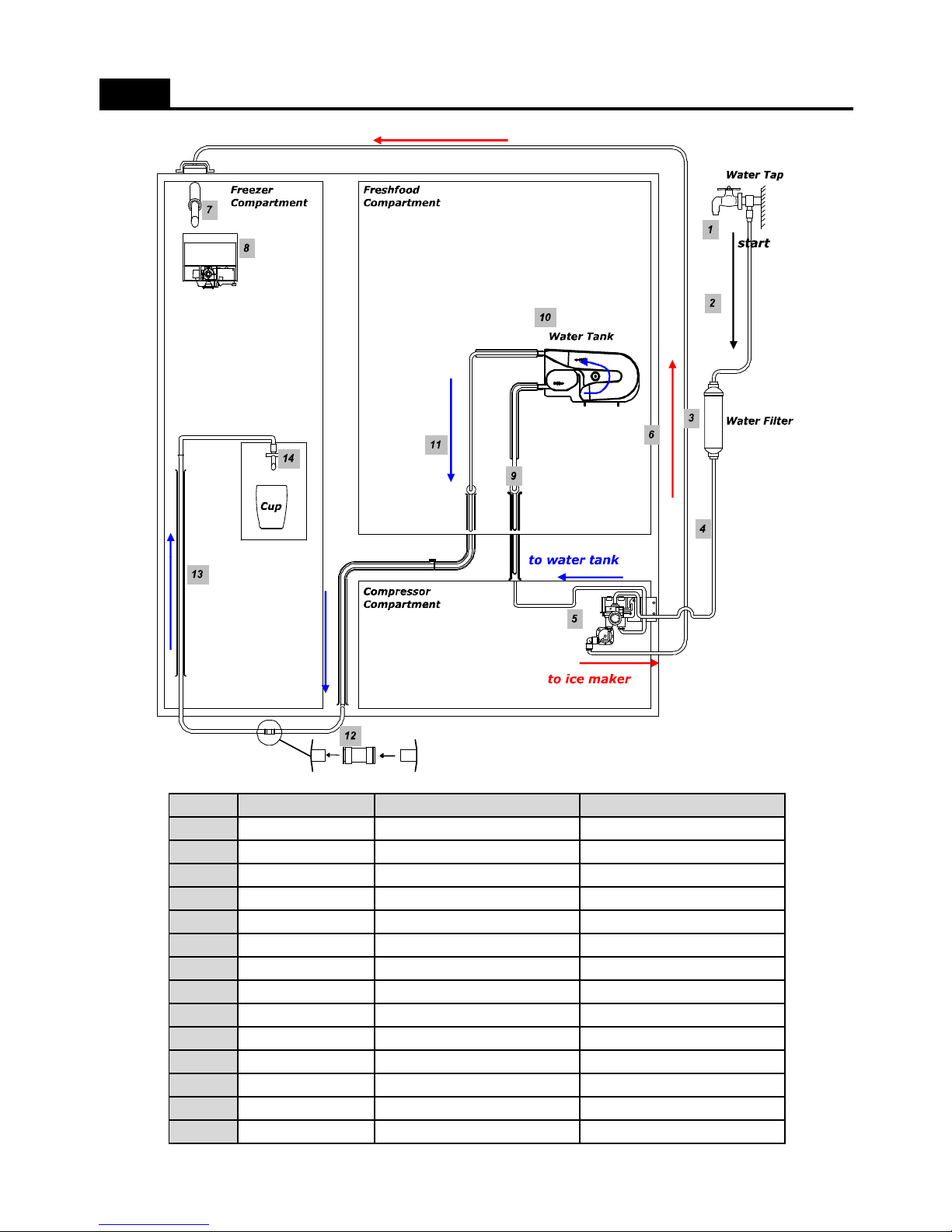
Water System for Dispenser Model
No
1
2
3
4
5
6
7
8
9
10
11
12
1
3
3014462210 PIPE DR WATER AS FRU-541D
3019504300 TUBE WATER D LDPE(OD)5/16
3013064200 HOLDER TUBE A A5UC5
3019504200 TUBER WATER C LDPE(OD)5/16, L1150
3018200901 TANK WATER HDPE-NATUAL HIVOREX 5200B
3013224830 HOSE I/MAKER TUBE AS FRU-54QD
3012205810 FRAME I/MAKER AS FRU-541D
3015402330 VALVE WATER AS FRU-54QD
3012519212 GUIDE CAB W/TUBE A AS FRU-541D,L1525
3019974100 S/PART WATER FILT FR-S650CD
3019503300 TUBE WATER B LDPE, (OD)1/4" X L1500
3014454520 PIPE CONN C POM
3019503200 TUBE WATER A LDPE, (OD)1/4" X L5000
Part NamePart Code Specification
3
14
3012519000 GUIDE DR WATER PIPE SILICON
52
Page 54
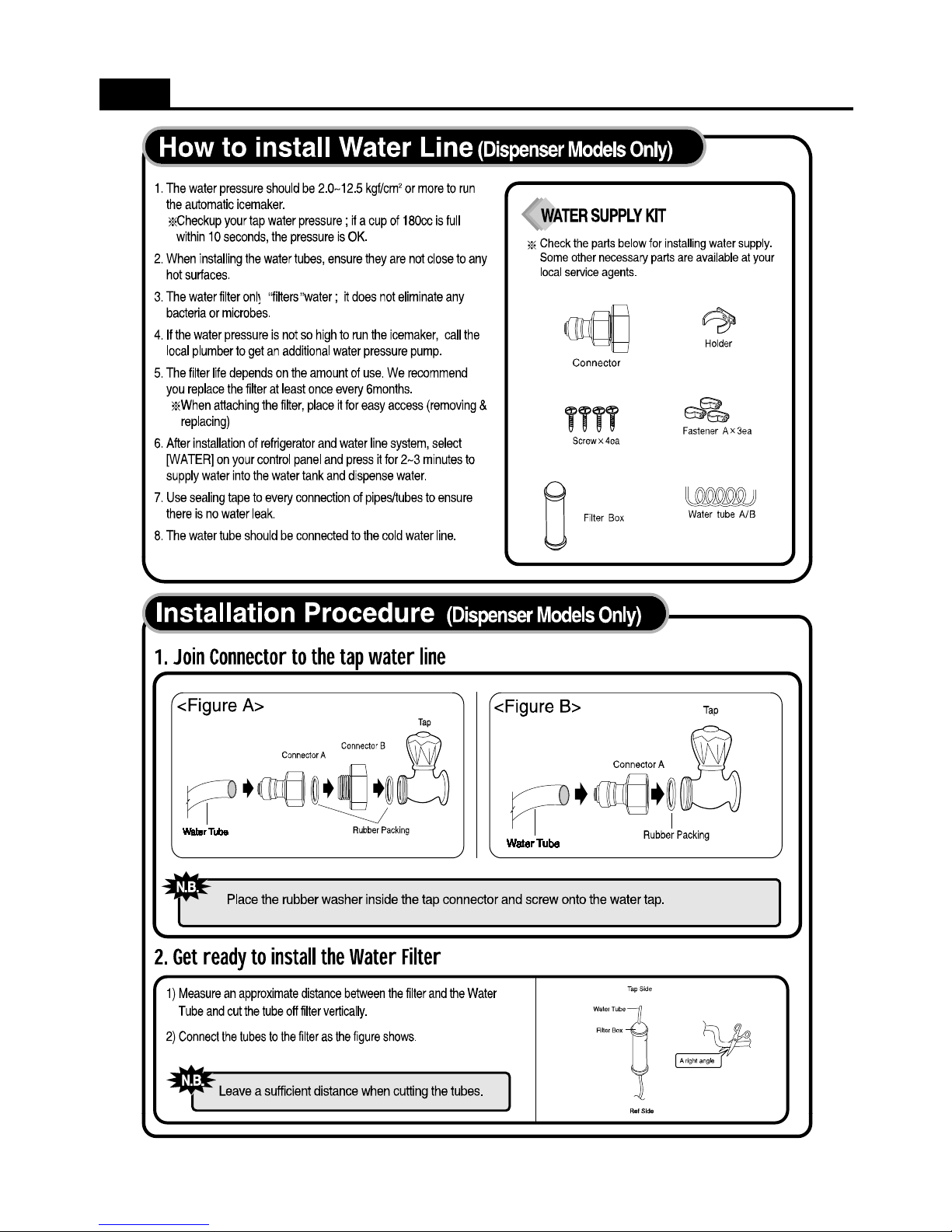
How to install water line ( Dispenser models only )
53
Page 55
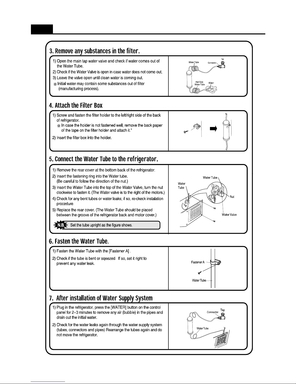
How to install water line ( Dispenser models only )
54
Page 56
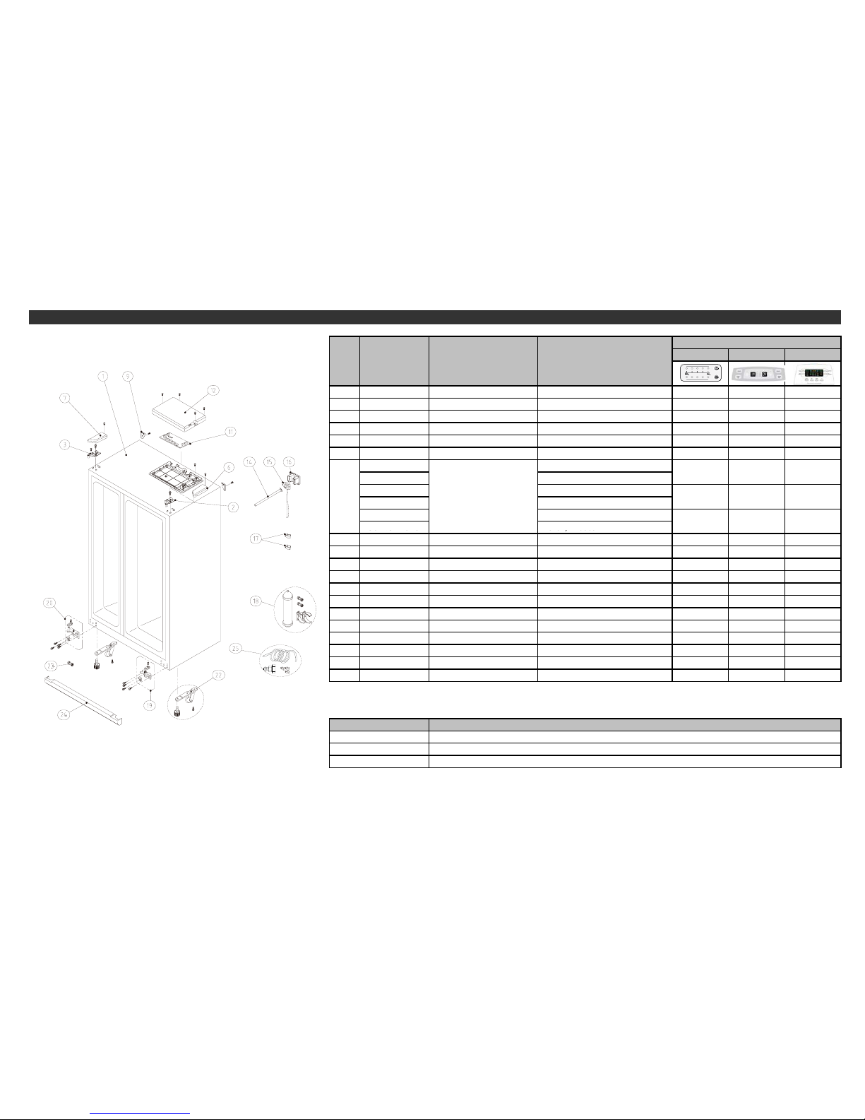
Inner Basic Basic Dispenser
-
--TRU BAC YSSA1
2
3012924400
111TNIA
P+0.3T
OPSA R* T* EGNIH
3
3012924300
11
1
TNIAP+0.3T OPSA L* T* EGNIH
6
3011446200 1
1
1PPR* T* IH REVO
C
7
3011446100
11
1P
PL* T* IH REVO
C
9 3010968400 22
2
P
PREVOC BAC PAC
30143D6061
FRU-571I, R-134a
30143D6070 FRU-571I, R-600a
30143E1020 FRU-579B, R-134a
30143E1060 FRU-573B, R600a
30143KA060
FRU-54, R-134a
-
-
xx
PCB MAIN AS x1
1
x1 x
x
Cabinet Parts
.CEPSEMAN TRAP
E
DOC-
TRA
PO
N
Q'ty
11
30143KA070
FRU 54, R 600a
12 3011446001 111)27-BF(PPXOB BCP/M REVOC
14
3013224800 1x
x
D145-UR
F
SA EBUT REKAM
/I ESOH
15 3012519210
1
xx5251L
SA A
EBUT/W BAC EDIUG
16
3011444100 1xx
SPI
H
A T
/W BAC
EDI
UG REVO
C
17 3011202000 2
xx
N5 ,66-APA EBUT RE
TAW PMA
LC
18
3019974800
1
xxWC066S-RFSA RETAW RETLIF TRAP/
S
19 3012924004 1
11
TNIA
P+0.5T
O/PSA R* U* EGNIH
20
3012923902 111TNIAP + 0.5T O/PSA L* U* EGNI
H
22 3010658002 2
22TNIAP KB
/6.2T/CCPS
SA TOOF JDA TEKCAR
B
23
3013064200 2
x
x5CU5AA EBUT REDLO
H
24 3011447230 COVER CAB BRKT AS COVER+VINYL(DAEWOO) 1 1 1
25
3019974020
S/PART W/TUBE AS W/DISPENSER EXPORT MODEL x x 1
- Some parts can be chaged for impr
oving their perfomance without notice.
55
A
mendment Note
Date
Page 57
Basic Dispenser
29 3010340402 BASE COMP AS FR-S570FRB(NO-HANDLE) 1 1
34 CORD POWER 1 1
3956183D2B MK183D-L2UB (110~127V)
3956183H4B MK183H-L2UB(220V/60Hz)
3956183Q5B MK183Q-L2UB(220~240V/50Hz)
395S130R50 HPL30YG-5 (220~240V/50Hz)
3956112250 DG125E11RAW5 (220~240V/50Hz)
36 3016002500 COMP WASHER SK-5 T0.8 3 3
3010101600 NBR Type
3010101480 SPRING Type
3018129710 445PHB,6R8M (MK183D-L2UB)
3018129720 265RFB,220M (MK183H-L2UB)
3018129600 265RHB,S330 (MK183Q-L2UB)
3018129810 308NHB,S330 (HPL30YG)
3018129650 232NFB,330M (DG125E11)
3811400503 COVER RELAY
3012610000 CLAMP BAND REL AY
SWITCH P RELAY AS 1 1
40
HPL30YG-5 DAEWOO COMP.
11
39
11
37 ABSORBER COMP 4 4
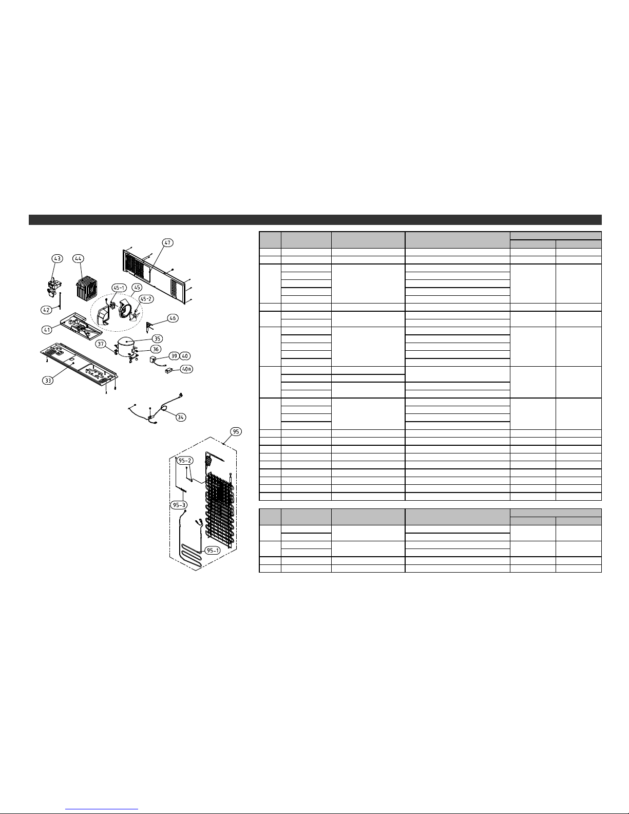
35 COMPRESSOR
Compressor Room & Eva. Part
NO PART-CODE PART NAME SPEC.
Q'ty
3811402100
MK183 Series SAMSUNG COMP
.
3001410000 DG125E11RAW5 PANASONIC COMP.
3016405020 250VAC/12
㎌
(MK183D..)
3016405900 350VAC/5
㎌
(MK183H, MK183Q..)
3016406100 400VAC/5
㎌
(HPL30YG..)
3016405800 350VAC/4
㎌
(DG125E..)
41 3011181310 CASE VAPORI AS FRS-551F PP(NATURAL) 1 1
42 3013201710 HOSE DRN B PE FRB-5970NB 1 1
43 3015402300 VALVE WATER AS FR-S660CW x 1
44 3014461530 PIPE WICON AS FRU-57(SBS) 1 1
45 3018500510 M/BELL AS FRU-571I PP(NATURAL) 1 1
45-1 3015916100 MOTOR C FAN D4612AAA22 1 1
45-2 3011834710 FAN PP OD3.17XD150 1 1
46 3016808100 DRYER AS SBS 12G 1 1
47 3011497001 COVER MACH RM AS FRU-571I 1 1
Basic Dispenser
3017053540 110~127V/192W
3017053550 220~240V/192W
3012818410 110~127V/192W
3012818310 220~240V/192W
95-2 3014806900 SENSOR D AS PBN-43 1 1
95-3 3017202010 FUSE TEMP AS AC250V 77C 10A 1 1
40a CAPACITOR RUN 1 1
NO PART-CODE PART NAME SPEC.
Q'ty
COVER RELAY
56
95-1 11
95
HEATER SHEATH AS
EVA AS 11
Page 58
Inner Basic Basic Di spenser
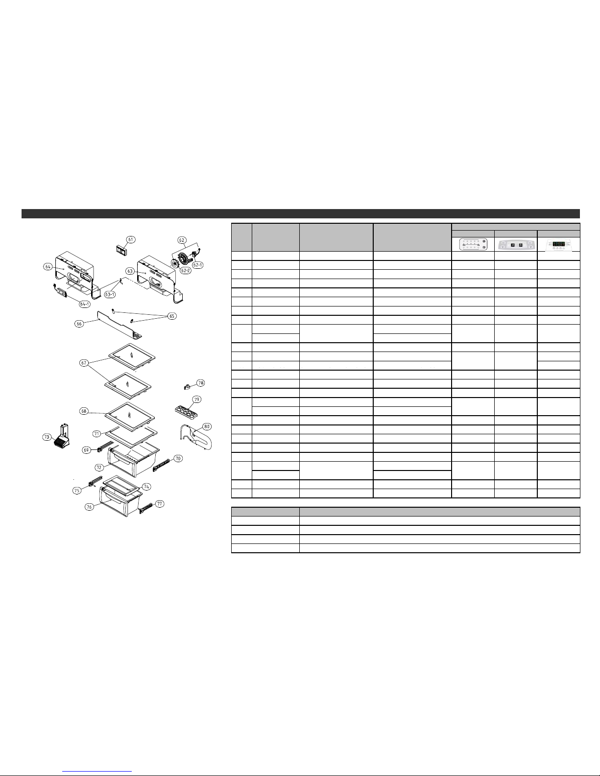
61 3012205001 FRAME CHECK VALVE AS FR-S580CG 1 1 1
62 3012024200 FIXTURE MOTR AS. 111
62-1 3015916000 MOTOR R FAN D4612AAA20 1 1 1
62-2 3011835410 FAN R PP OD3.17XD95 1 1 1
63 3011495100 COVER DAMP AS FRU-541D x 1 1
63-1 3014807100 SENSOR R AS PBN-43B 1 1 1
64 3011492800 COVER DAMP AS FRU-571 1 x x
64-1 3014235200 PANEL CONTL *I AS . 1 x x
3013602800 AC 110~127V, 25W
3013602500 AC 220~240V, 25W
66 3015510800 WINDOW R LAMP MIPS 1 1 1
67 3017842821 SHELF INMOLDING R A AS FRAME+PRINTED GLASS 2 2 2
2265 LAMP F/R
Q'ty
2
Refrigerator Compartment
SPEC.PART NAMEPART-CODENO
68
3017843321
SHELF INMOLDING R C AS
FRAME+PRINTED GLASS
111
69 3012514512 GUIDE CASE A *L AS FR-S580EG(PP) 1 1 1
70 3012514612 GUIDE CASE A *R AS FR-S580EG(PP) 1 1 1
71 3017842921 SHELF INMOLDING R B AS FRAME+PRINTED GLASS 1 1 1
3011114670 CASE VEGETB B AS FRU-571, CRYSTAL
3011114630 CASE VEGETB B AS FRU-571, BLUE
73 3011476011 COVER RETURN DUCT AS FRU-571I 1 1 1
74 3011446700 COVER VEGETB CASE B GPPS 1 1 1
75 3012529712 GUIDE CASE C *L AS PP 1 1 1
76 3011114770 CASE VEGETB C AS FRU-571, CRYSTAL 1 1 1
77 3012529812 GUIDE CASE C *R AS PP 1 1 1
3018124000 SP201R-7DR(R-134a)
3018128500 SPF101B-2D(R-600a)
79 3011190800 CASE EGG TRAY GPPS 1 1 1
80 3018201000 TANK WATER AS FRU-541D x x 1
- Some parts can be chaged for improving their perfomance without notice.
1
172 11
78 SWITCH DR
Date
A
mendment Note
11
Page 59
Basic Dispenser
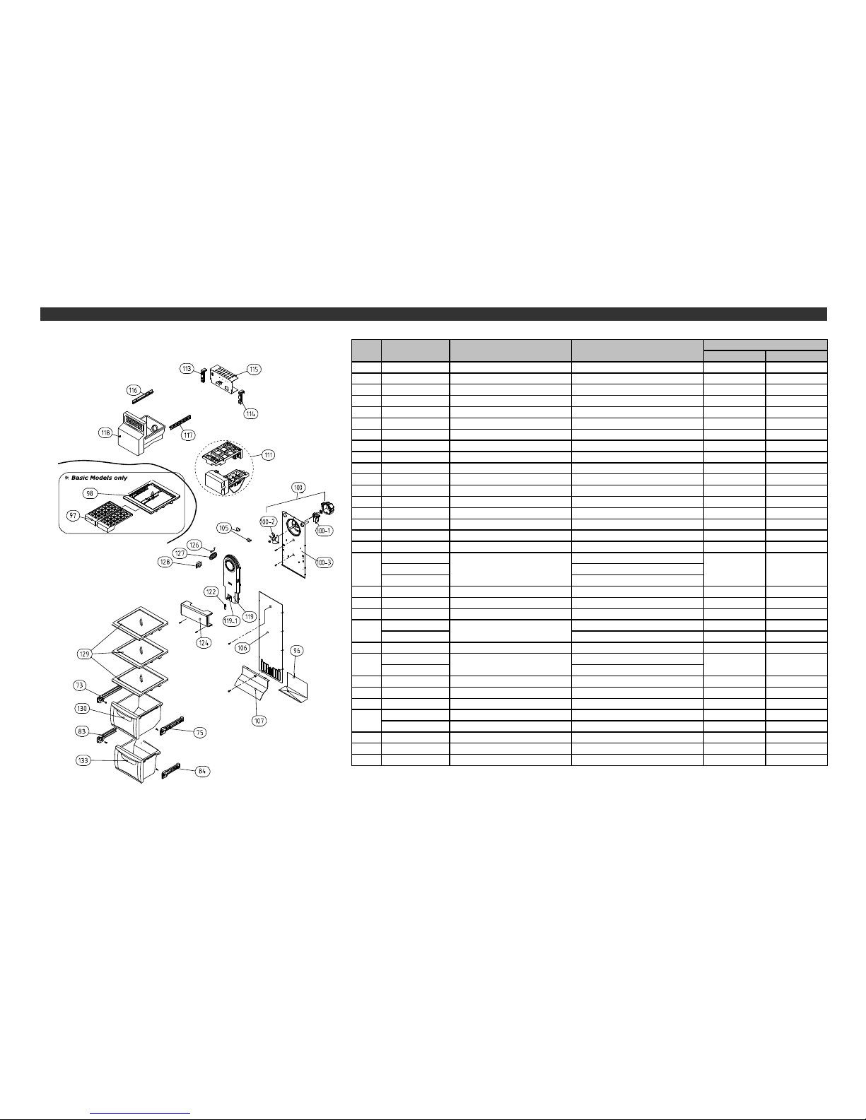
73 3012514512 GUIDE CASE A *L AS FR-S580EG(PP) 1 1
75 3012514612 GUDIE CASE A *R AS FR-S580EG(PP) 1 1
83 3012529712 GUIDE CASE C *L AS PP 1 1
84 3012529812 GUIDE CASE C *R AS PP 1 1
96 3012529010 GUIDE DRN EGI SCRAP T0.4*W248*L140 1 1
97 3011186310 CASE ICE PP+PRINT 2 x
98 3017842710 SHELF F ICE AS FRAME+PRINTED GLASS+FIXTURE 1 x
100 3018921710 LOUVER F A AS FRU-571I 1 1
100-1 3015915900 MOTOR F FAN D4612AAA21 1 1
100-2 3011834520 FAN PP OD130 1 1
100-3 3018921300 LOUVER F A ABS 1 1
105 3010924600 CAP F LOUVER HIPS T2.3 2 1
106 3018921501 LOUVER F B AS HIPS 1 1
107 3011443200 COVER F RETURN HIPS 1 1
111 3012205810 FRAME I/MAKER AS FRU-541D x 1
Freezer Compartment
NO PART-CODE PART NAME SPEC.
Q'ty
113 3012517800 GUIDE G/MOTR BRKT *L ABS x 1
114 3012517900 GUIDE G/MOTR BRKT *R ABS x 1
3010671520 110~127V/60Hz
3010671540 220V/60Hz
3010671560 220~240V/50Hz
116 3012520510 GUIDE ICE CRUSHER *L ABS x 1
117 3012517710 GUIDE ICE CRUSHER *R ABS x 1
118 30111152C0 CASE I/CRUSHER AS FRU-54VD/VF(C-600 VE MODEL) x 1
3001401750 FRU-571I 1 x
3001401760 FRU-541/547/549/54B x 1
119-1 3017906610 SOCKET F LAMP AS FR-S570FRB 1 1
3013602800 AC 110~127V, 25W
3013602500 AC 220~240V, 25W
124 3015510700 WINDOW F LAMP MIPS 1 1
126 3014807000 SENSOR F AS PT-38 1 1
127 3011442600 COVER F SENSOR ABS 1 1
3018128500 SWITCH DR SPF101B-1D (R-600a) 1 1
3018128500 SWITCH DR SPF101B-1D (R-600a) 1 1
129 3017842600 SHELF F AS PRINTED GLASS 3 3
130 3011114870 CASE F A AS FRU-541, CRYSTAL 1 1
133 3011114970 CASE F B AS FRU-541, CRYSTAL 1 1
- Some parts can be chaged for improving their perfomance without notice.
58
119 COVER F FAN AS
115 BRACKET GEARED MOTR AS x 1
128
122 LAMP F/R 11
Page 60
Inner Basic Basic Dispenser
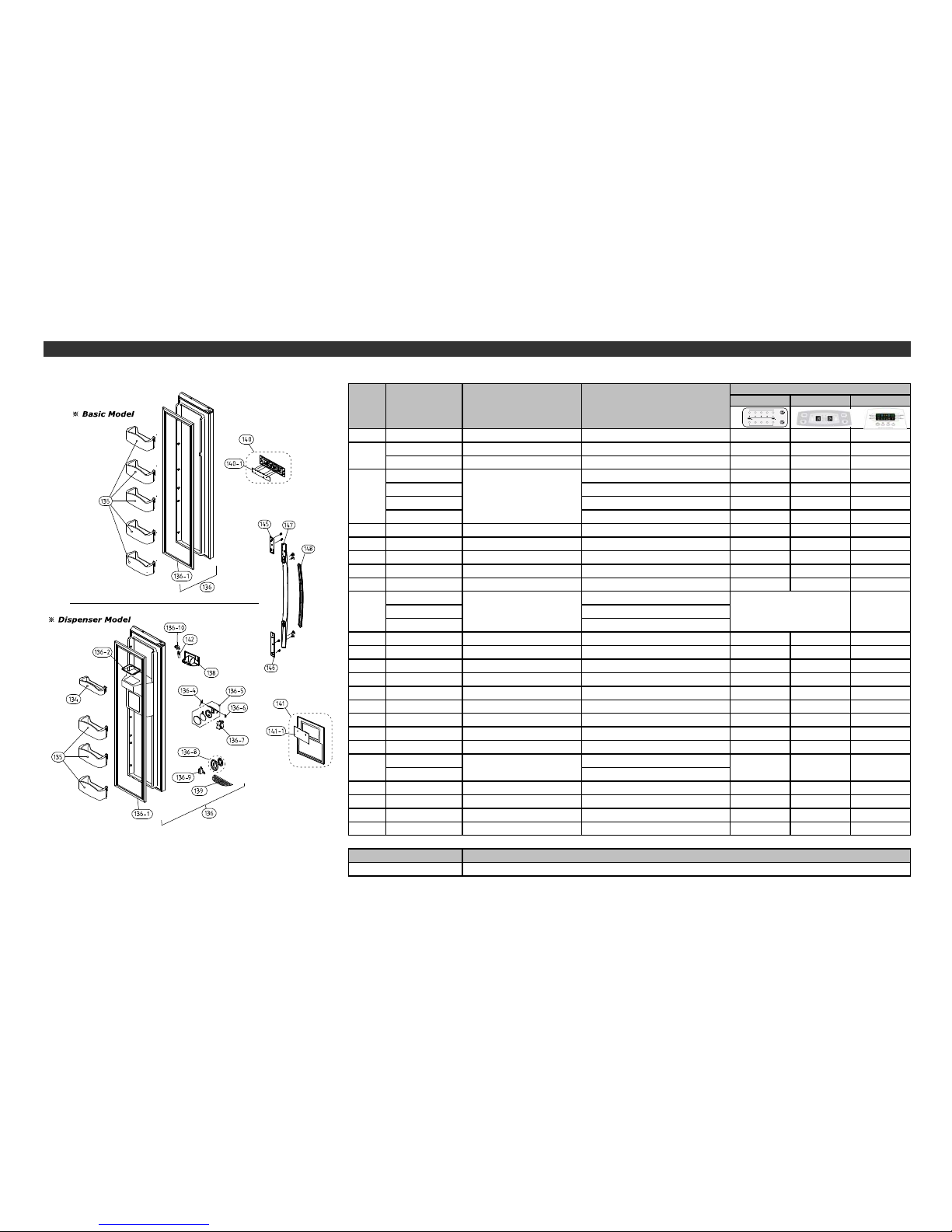
134 3019026700 POCKET F *T HIPS
xx1
3019026600 POCKET F HIPS
xx3
3019027401 POCKET F AS FRU-541D
553
30000604E0 FRU-57VI(TITANIUM ELLIO)
1xx
30000604F0 FRU-57VI(DE WHITE)
1xx
30000606C0 FRU-54VD/F, TITANIUM ELLIO
xx1
30000606D0 FRU-54VD/F, DE WHITE
xx1
136-1 3012318830 GASKET F DR AS PVC+MAGNET
111
136-2 3010964601 CAP ICE PATH FRAME PP(FRS-551F)
xx1
136-4 3015102200 SPRING ICE D LEVR SUS
xx1
136-5 3011495300 COVER I/FLAP AS FRU-541D
xx1
Freezer Door
NO PART-CODE PART NAME SPEC.
136 ASSY F DR
Q'ty
135
136-6
3012019700
FIXTURE I/SHUT LUVR
FR-S650CD
xx1
3015402100 220V 60HZ
3015403120 110~127V/60z
3015403000 220~240V/50Hz
136-8 3016304941 BUTTON DISPNS AS ABS+AL
xx1
136-9 3018125800 SWITCH MICRO VP333A-2D
xx1
136-10 3017903702 SOCKET LAMP AS -
xx1
138 3010544000 BOX DISPNS ICE SHUT AS FRU-541D
xx1
139 3012406900 GRILLE DISPNS ABS
xx1
140 3001401040 COVER F PCB AS EXPORT(FRU-579B/H)
x1x
140-1 30143E1110 PCB FRONT AS FR-S570ERB
x1x
141 3011494780 COVER DISPNS BOX AS FRU-54V
xx1
141-1 30143KA160 PCB FRONT AS FRU-54V
xx1
3013600050 110~127V/15W
3013600020 220~240V/15W
145 3010339100 BASE HNDL *T HIPS
111
146 3010339200 BASE HNDL *U HIPS
111
147 3012640900 HANDLE F/R AS FR-S580DVB 1
11
148 3011636010 DECO HANDL F/R ABS(NO SPRAY)
111
- Some parts can be chaged for improving their perfomance without notice.
x
LAMP AS
xx
1
A
mendment Note
142
1
Date
136-7 VALVE SOL DISP
Page 61
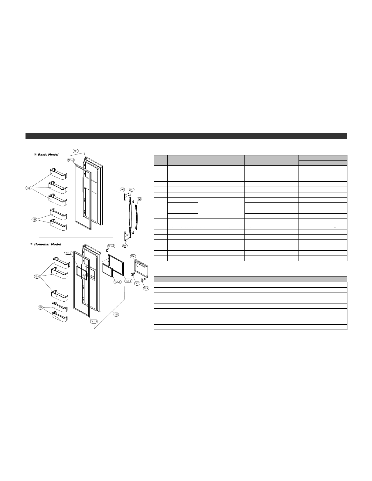
Basic H/Bar
145 3010339100 BASE HNDL *T HIPS
11
146 3010339200 BASE HNDL *U HIPS
11
147 3012640900 HANDLE F/R AS FR-S580DVB 1
1
148 3011636010 DECO HANDL F/R ABS(NO SPRAY)
11
156 3019026800 POCKET R HIPS 3
3
159 3019026900 POCKET R *S FRU-571I 2
2
30000607B0 FRU-54VF(TITANIUM) X 1
30000607C0 FRU-54VF(DE WHITE) X 1
30000607D0 FRU-57VI(TITANIUM) 1 X
30000607E0 FRU-57VI(DE WHITE) 1 X
161-1 3012318930 GASKET R DR AS PVC+MAGNET 1
1
-
161
NO
ASSY F DR
Q'ty
Refrigerator Door
SPEC.PART NAMEPART-CODE
161 2
3012319300
GASKET H/BAR B AS
PVC
x
1
161-3 3018125601 SWITCH H/BAR DR AS SP101B-2D1(G) GRAY x
1
161-4 3012319400 GASKET H/BAR A AS PVC x
1
161-5 3011497200 COVER H/BAR FRAME FRU-541F x
1
162 3015204500 STOPPER H/BAR DR *R PO T4.0 x
1
163 3015204400 STOPPER H/BAR DR *L PO T4.0 x
1
164 3011767902 DOOR H/BAR AS FRU-541F x
1
- Some parts can be chaged for improving their perfomance without notice.
Date
60
 Loading...