

Page 1
ELT-3020AP SERVICE MANUAL
E-RAE ELECTRONICS
MODEL NAME DOCUMENT NO REVISION NO REVISION DATE PAGE
ELT-3020AP RD(1) 00 04/03/31 1/55
Page 2

ELT-3020AP SERVICE MANUAL
E-RAE ELECTRONICS
CONTENTS
SPECIFICATION ..................................................................... 4
CONTROL DESCRIPTIONS .............................................. 7
REMOTE CONTROL BUTTONS ....................................... 9
INSPECTION CRITERIA .................................................. 11
BLOCK & WIRING DIAGRAM ......................................... 12
MODULE BASIC CONFIGURATION ............................... 14
A/D BOARD PIN CONFIGURATION ................................ 15
OSD MENU(FACTORY) ................................................... 19
DESCRIPTION OF A/D FUNCTIONS .............................. 30
CIRCUIT OPERATION & WAVEFORM ............................ 32
MODULE POWER SEQUENCE ...................................... 39
WHITE BALANCE ADJUSTMENT .................................. 40
POWER BOARD PIN CONFIGURATION .......................... 43
MODULE PRECAUTIONS .............................................. 44
TROUBLE SHOOTING ............................................. 45
MODEL NAME DOCUMENT NO REVISION NO REVISION DATE PAGE
ELT-3020AP RD(1) 00 04/03/31 2/55
Page 3

ELT-3020AP SERVICE MANUAL
E-RAE ELECTRONICS
EXPLODED VIEW PARTS LIST ...................................... 47
REPLACEMENT PARTS LIST(PAL TV) .......................... 50
EXPLODED VIEW ........................................................... 55
MODEL NAME DOCUMENT NO REVISION NO REVISION DATE PAGE
ELT-3020AP RD(1) 00 04/03/31 3/55
Page 4

ELT-3020AP SERVICE MANUAL
E-RAE ELECTRONICS
SPECIFICATIONS
Note : Specification and others are subject to change without notice for improvement.
● TV
1.Input Signal :
PAL
SECAM
SD,HD
VGA ~SXGA
2. Tuner : PAL
SECAM
2. Input Voltage : AC 100V ~ 240V, @ 50/60Hz, 2A
3. Power Consumption : 150W
Stand-by : 5W
4. LCD Module : V296W1 - ### (CHIMEI)
5. Speaker Impedance : 8Ω
6. Sound Output : 7W + 7W (Max)
7. Feature :
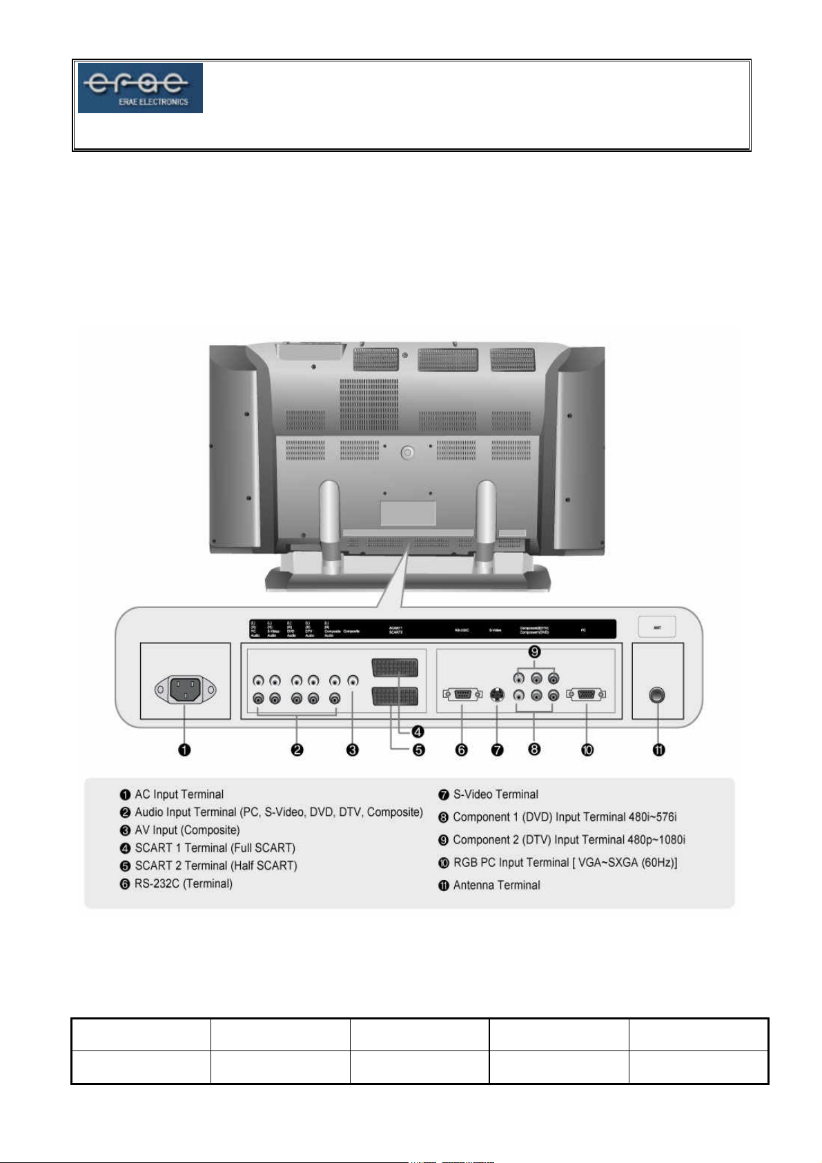
- AV Input
- Component1 Input (DVD)
- Component2 Input (DTV)
- D-SUB (Analog RGB 15 pin)
- S-Video Input
- Composite Input
- SCART1 Input (Full)
- SCART2 Input (Half)
- Tuner (PAL,SECAM)
- Audio Input (Composite, Component 1/2, S-Video, PC)
- RS-232C (9 pin), TCP / IP Support (0~254set)
8. Function :
- ARC
- PIP
- PBP (4:3,16:9)
- MTS
- TTX
MODEL NAME DOCUMENT NO REVISION NO REVISION DATE PAGE
ELT-3020AP RD(1) 00 04/03/31 4/55
Page 5
ELT-3020AP SERVICE MANUAL
9. External Interface
1) AV / COMPONENT Output
ITEM MIN TYP MAX UNIT
AV Video Input Level 0.85 1.00 1.15 Vpp
AV Sync Input Level 0.24 0.29 0.32 Vpp
AV Burst Input Level 0.14 0.28 0.35 Vpp
AV Video Input Level 0.47 0.63 0.79 V
AV Audio Input L/R 0.47 0.63 0.79 V
Component Video Input Level
(Y,Cb/Pb,Cr/Pr)
Analog RGB, H/V Input Level 0.6 0.7 0.8 Vpp
2) COMPONENT Mode (Y,Cb/Pb,Cr/Pr)
RESOLUTION H-Freq(KHz) V-Freq(Hz) Proposed
720*480 15.73 60.00 SDTV,DVD 480i
720*576 15.63 50.00 SDTV,DVD 576i
720*480 31.47 59.94 SDTV 480p
1280*720 45.00 60.00 HDTV 720p
1280*720 44.96 59.94 HDTV 720p
1920*1080 33.75 60.00 HDTV 1080i
1920*1080 33.72 59.94 HDTV 1080i
3) SUPPORTING DISPLAY Mode
RESOLUTION H-Freq(KHz) V-Freq(Hz)
31,47 60
640*480
720*400 31.47 70
800*600
1024*768
1280*1024 64.00 60
37.86 72
37.50 75
35.15 56
37.88 60
48.88 72
46.88 75
48.36 60
56,48 70
60.02 75
E-RAE ELECTRONICS
0.6 0.7 0.8 Vpp
MODEL NAME DOCUMENT NO REVISION NO REVISION DATE PAGE
ELT-3020AP RD(1) 00 04/03/31 5/55
Page 6
10. RS-232C Signal
Pin No Pin Name Spec Pin No Pin Name Spec
ELT-3020AP SERVICE MANUAL
1 DCD NC 6 DSR NC
2 RXD 12 Vpp 7 RTS NC
3 TXD 12 Vpp 8 CTS NC
4 DTR NC 9 R NC
5 GND GND
E-RAE ELECTRONICS
MODEL NAME DOCUMENT NO REVISION NO REVISION DATE PAGE
ELT-3020AP RD(1) 00 04/03/31 6/55
Page 7
ELT-3020AP SERVICE MANUAL
E-RAE ELECTRONICS
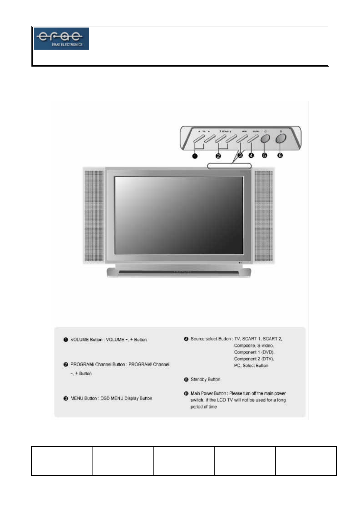
CONTROL DESCRIPTIONS
MODEL NAME DOCUMENT NO REVISION NO REVISION DATE PAGE
ELT-3020AP RD(1) 00 04/03/31 7/55
Page 8
ELT-3020AP SERVICE MANUAL
E-RAE ELECTRONICS
MODEL NAME DOCUMENT NO REVISION NO REVISION DATE PAGE
ELT-3020AP RD(1) 00 04/03/31 8/55
Page 9
ELT-3020AP SERVICE MANUAL
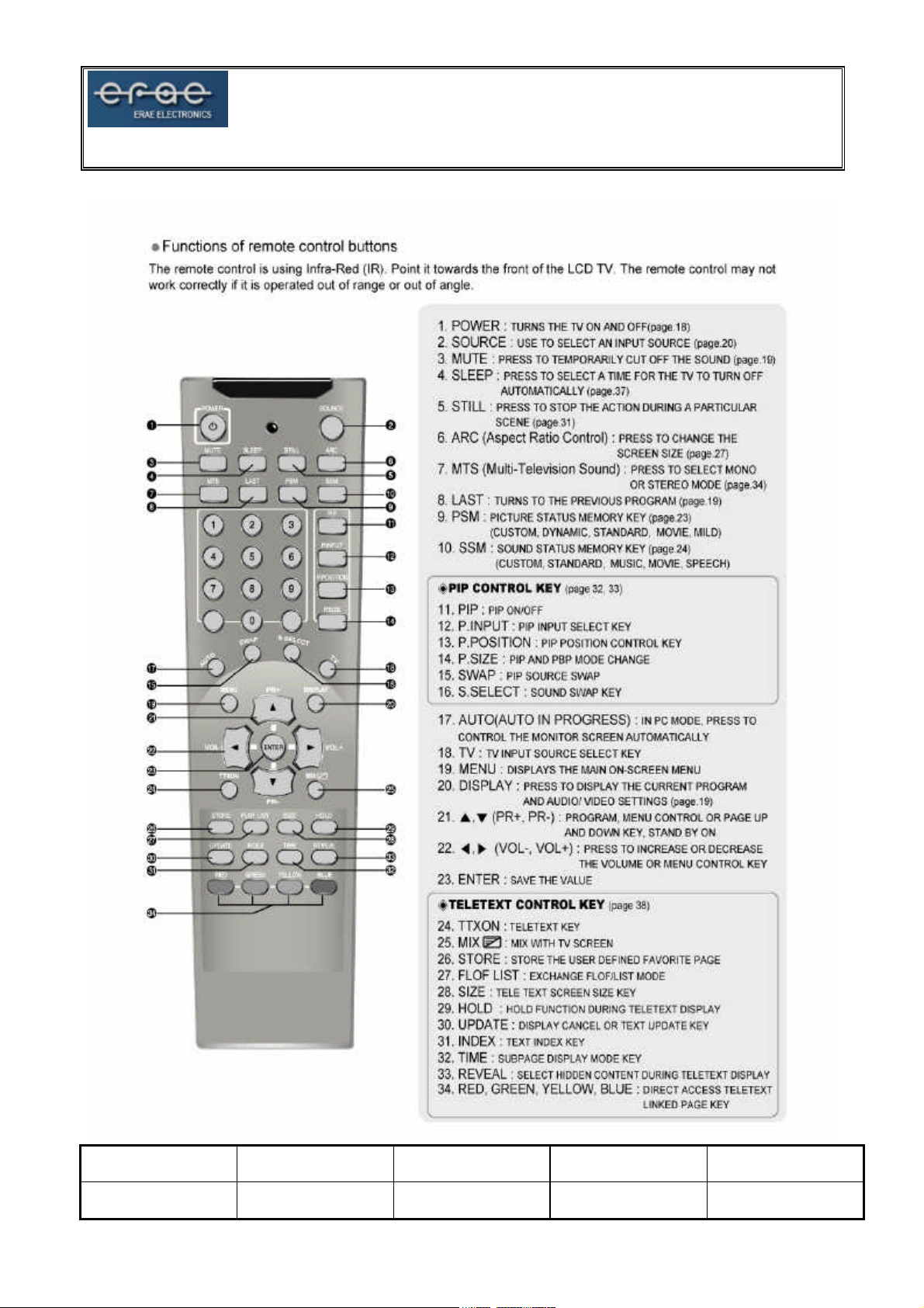
REMOTE CONTROL BUTTONS
E-RAE ELECTRONICS
MODEL NAME DOCUMENT NO REVISION NO REVISION DATE PAGE
ELT-3020AP RD(1) 00 04/03/31 9/55
Page 10

■
TELETEXT FUNCTION
ELT-3020AP SERVICE MANUAL
E-RAE ELECTRONICS
MODEL NAME DOCUMENT NO REVISION NO REVISION DATE PAGE
ELT-3020AP RD(1) 00 04/03/31 10/55
Page 11
ELT-3020AP SERVICE MANUAL
E-RAE ELECTRONICS
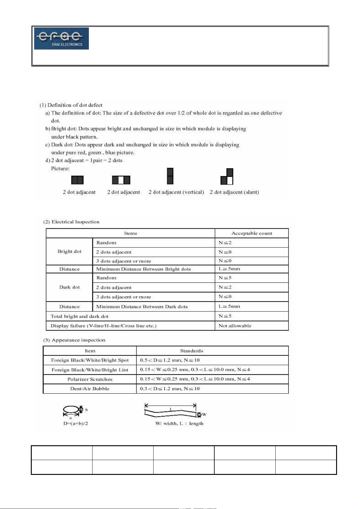
INSPECTION CRITERIA
MODEL NAME DOCUMENT NO REVISION NO REVISION DATE PAGE
ELT-3020AP RD(1) 00 04/03/31 11/55
Page 12
ELT-3020AP SERVICE MANUAL
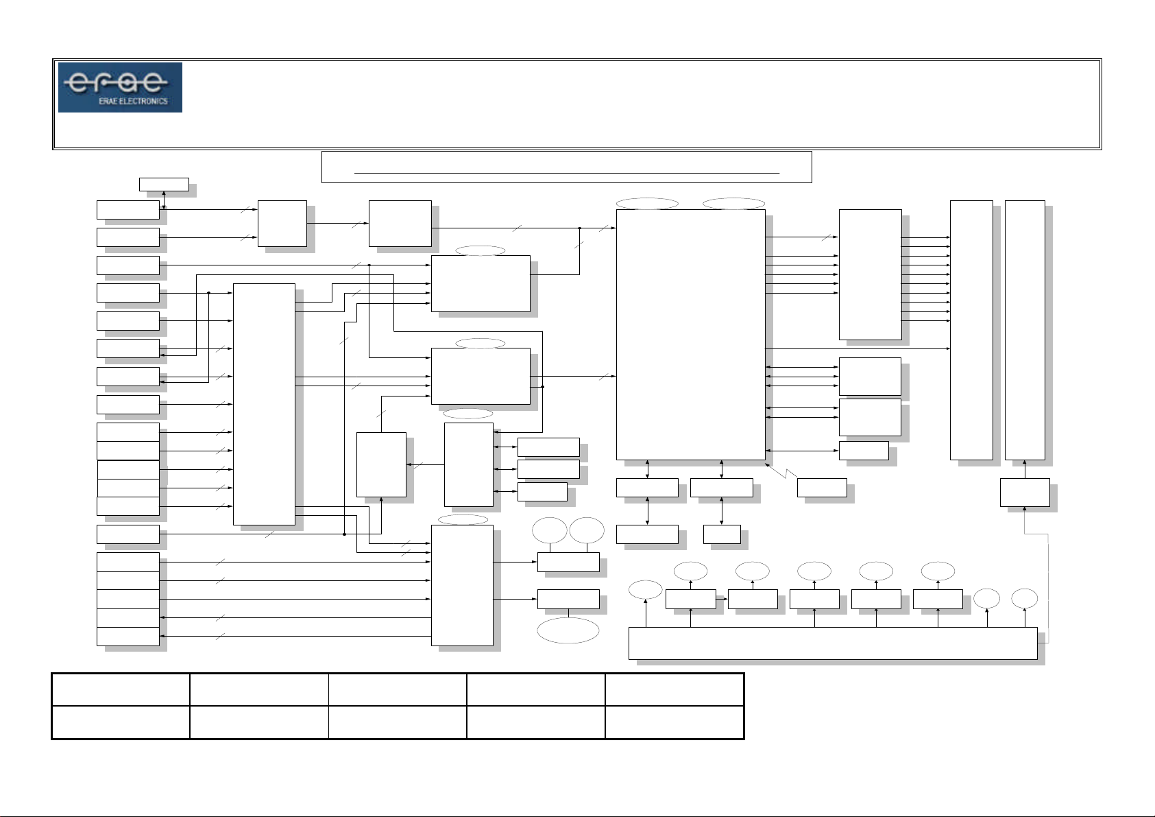
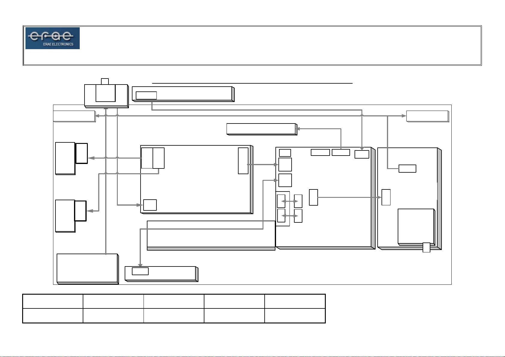
E-RAE ELECTRONICS
A NA L OG R G B
C O M P O N E NT1
(D T V)
C O M P O N E NT2
(D V D)
T UN E R
C V BS
C OM P O S IT E
IN
H AL F SCA R T
V ID E O IN /OU T
F UL L SCA R T
V ID E O IN /OU T
S -V ID EO
S -V ID EO
A UD IO IN
P C
A UD IO IN
S CAR T _FU L L
A UD I O IN
S CAR T _ HA L F
A UD IO IN
C OM P O S IT E
A UD IO IN
F UL L SCA R T
R G B
D TV
A UD IO IN
D V D
A UD IO IN
T UN E R
S IF
S CAR T _ FU L L
A UD IO O U T
S CAR T _ HA L F
A UD IO O U T
24L C21
E EPR O M
R ,G ,B ,H, V 5
Y,P b, Pr
Y,P b, Pr
C VB S ,ID
C VB S ,ID
C H ,L U 2
SVIDE O _I N R /L
PC_ IN R / L
F _S C _IN R/L
H _S C _I N R /L
A V_ IN R /L
SCAR T R GB(R ,G ,B ,F B )
D TV _IN R /L
D VD _ IN R /L
3
2
2
C XA 2 08 9Q
M UX(U3 )
2
2
2
2
2
2
2
F_C V BS _ OUT _ R/ L
2
H _C V BS_ O UT_ R/L
2
A /V
(U 8)
B A7 65 7
S W IT CH
4
V O UT2
Y,C O U T2
4
V O UT1
Y,C O U T1 2
M SP0 L /R
M SP1 L /R
3 0 " L C D T V P A L P W 5 6 5 B L O C K D IA G R A M
5
3
2
A D9 883
C ON V E R T ER
BA7 65 7
(U 28 )
S W IT CH
(U 2)
A /D
4
TTX R G B
(R ,G, B,FB)
4
2
2
20 .2 5M H z
V P C3 23 0 D-C5
V ID EO
D ECO D E R
H _S C ART _OUT
20 .2 5M H z
V P C3 23 0 D-C5
V ID EO
D ECO D E R
(M A IN )
6.00 0M H z
S DA5 55 0
(U 26 )
T TX
18.4 32 M Hz
(U 45)
M S P34 53
A UD IO
P R O C E S S OR
(U 39)
(S U B)
(U 41)
24
TTX _CV B S
S ST 39V F0 8 0A T
E E PR O M
M SP_ O UT1
L / R
M SP_ O UT2
L / R
C H1 RG B
C H1 GB
C H2 GB
FLA SH
H Y6 2U8 200
R AM
24L C1 6
S PKRS PK
T DA 7 26 6
A UD I O A M P
T S482ID
A UD I O A M P
H EA D P HON E
20 .0 00 M Hz
24
16
P W 565
16
D S232A S
R S 23 2
T R AN S M IT TER
L
R /L
R S 23 2
D SUB -9P
VCC 12
12V
A P1501 -50
12V 12V 12 V 1 2V
(U 2 1)
VCC 5
80.0 00 M H
I/O E XTE N D ER
K YE
P AD
VCC 3
R C 11 17
D R G B[2 3: 0]
D HS
D VS
D EN
D CLK
L V D S O N
LCD P W O N
A DR[ 12:0]
F SD Q M [7:0]
FSD A TA[ 63:0]
A [2 1:0]
D [7 :0 ]
R E M OC O N
VCC 5 A
A P1 501 -50
24
P O W ER
M O DU L E
T HC 6 3L V DM83 R
LVDS
T R AN S M IT TER
K 4S 6 43 23 2E X 2
S DRA M
TM 2 8F8 00 B 3
F LA SH
M O M O R Y
24 L C2 56
E E PR O M
V CC 5 D VC C 9
A P1 501 -50
O D D0O D D0+
O D D1O D D1+
D2-
O
D
O D D2+
O D D3-
O D D3+
O DDC L KO DDC L K+
K IA 78 09
T FT L CD
M O DU L E
30 "
5V
5VS T
B AC K
LIG HT
IN V E R TE R
FAN
12V
24V
MODEL NAME DOCUMENT NO REVISION NO REVISION DATE PAGE
ELT-3020AP RD(1) 00 04/03/31 12/55
Page 13
ELT-3020AP SERVICE MANUAL
E-RAE ELECTRONICS
E L T - 3 0 2 0 A P L C D T V W I R I N G D I A G R A M
S P E A K E R
_ R
I N V E
R T E R
I N V E
R T E R
I N N E T
1 2
P
1 0
P
A C
S / W
8 P
1 5
P
C N 3 C N 4
C N 1
6 P
2 P
1 5
P
P S U
I R / L E D
O S D K E Y
I / O B O A R D
L C D P A N E L 2 0 P
C N 2
1 2
P
1 5 P
J 1
J 2
S P E A K E R
_ L
J 1
J 2
2
4
P
2 1 P
3 P
C O N 3
1 2
C O N 4
P
C O N 2
6 P
2
2
4
4
P
P
2
2
4
4
P
P
3 1 P
P 3
C O N 5
M A I N
B O A R D
J 5
8 P
C O N 1
C O N 1
T U N E R
2
4
B O A R D
P
J 5
4 P
T U N ER
MODEL NAME DOCUMENT NO REVISION NO REVISION DATE PAGE
ELT-3020AP RD(1) 00 04/03/31 13/55
Page 14
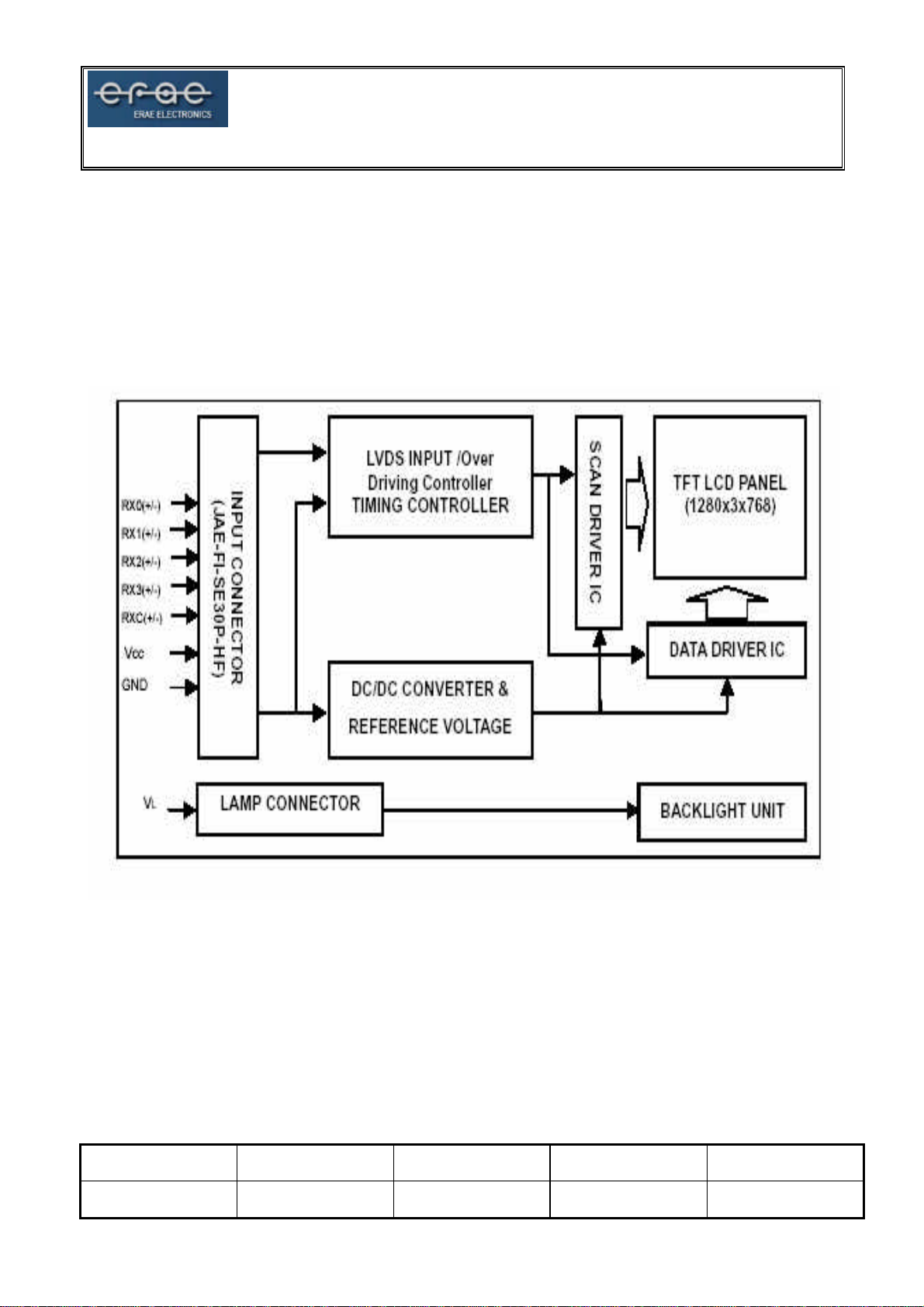
MODULE BASIC CONFIGURATION
[V296W1 - ###]
ELT-3020AP SERVICE MANUAL
E-RAE ELECTRONICS
MODEL NAME DOCUMENT NO REVISION NO REVISION DATE PAGE
ELT-3020AP RD(1) 00 04/03/31 14/55
Page 15
ELT-3020AP SERVICE MANUAL
A/D BOARD PIN CONFIGURATION
Pin No I/O Specification Description
1 ( +12V ) I +12V MAIN B/D 12V Input
2 ( +12V ) I +12V MAIN B/D 12V Input
3 ( AC_DET ) I +5V AC_DETECT PIN
4 ( GND ) GND Ground
5 ( GND ) GND Ground
6 ( GND ) GND Ground
CON4
CON2
7 ( S5V ) I S5V MAIN 5V Input
8 ( GND ) GND Ground
9 ( BRITE_ADJ ) O
10 ( GND ) GND Ground
11 ( BKL_ON ) O BACKLIGHT_ON LCD Backlight ON
12(POWER_
ON/OFF )
1 ( GND ) GND Ground
2 ( LEDG ) O LED_GREEN GREEN LED CONTORL OUTPUT PORT
3 ( LEDR ) O LED_RED RED LED CONTORL OUTPUT PORT
4 ( IR ) I 5V / 0V
5 ( GND ) GND Ground
6 ( VCC ) O 5V / 0V OSD B/D 5V Output
O POWER_ON/OFF POWER ON_OFF Control
BRIGHTNESS_ADJUST
LCD Brightness Adjustment
: High : Green LED On
: High : Red LED On
IR RECEIVER SIGNAL INPUT PORT
E-RAE ELECTRONICS
1 ( POWER ) I 5V / 0V
2 ( SOURCE ) SOURCE SELECT Input Source Selecting
3 ( MENU ) I MENU OSD MENU Display
CON1
4 ( CH+ ) I CHANNEL UP TV CHANNEL CONTROL(UP)
5 ( CH- ) I CHANNEL DOWN TV CHANNEL CONTROL(DOWN)
6 ( VOL+ ) I VOLUME UP SOUND CONTROL(VOLUME UP)
7 ( VOL- ) I VOLUME DOWN SOUND CONTROL(VOLUME DOWN)
8 ( GND ) GND Ground
MODEL NAME DOCUMENT NO REVISION NO REVISION DATE PAGE
POWER S/W PORT
:DC POWER ON_OFF
ELT-3020AP RD(1) 00 04/03/31 15/55
Page 16
ELT-3020AP SERVICE MANUAL
1 ( VCC12) VCC12 Power Supply +12.0V
2 ( VCC12) VCC12 Power Supply +12.0V
3 (VCC5A) VCC5A Power Supply +5.0V
4 (MSP_L_OUT1)
5 (MSP_R_OUT1)
6 (GND) GND Ground
7 (MSP_L_OUT2)
8 (MSP_R_OUT2)
9 (GND) GND Ground
10 (AFT) I AFT
J5
11 (TUNER_SIF) I TUNER_SIF RF TV Sound Input
12( (GND) GND Ground
13 (TUNER_CVBS)
14 (GND) GND Ground
15 (S_MUTE) O S_MUTE Sound Mute
16 (AMP_ST-BY)
17 (HEAD_MUTE)
18 (GND) GND Ground
19 (SDA3) SDA3 I2C Protocol
20 (SCL3) SCL3 I2C Protocol
O MSP_L_OUT1 MSP LEFT Sound Output1
O MSP_R_OUT1 MSP RIGHT Sound Output1
O MSP_L_OUT2 MSP LEFT Sound Output2
O MSP_R_OUT2 MSP RIGHT Sound Output2
I TUNER_CVBS RF TV Video Input
O AMP_ST-BY
I HEAD_MUTE Head Phone Mute
E-RAE ELECTRONICS
1 (VCC5) VCC5 Power Supply +5.0V
J1
2 (VCC5) VCC5 Power Supply +5.0V
3 (SCART_R) I SCART_R Full Scart Red Input
4 (SCART_G) I SCART_G Full Scart GREEN Input
5 (SCART_B) I SCART_B Full Scart BLUE Input
6 (SCART_FB) I SCART_FB
7 (GND) GND Ground
8 (FSCART_CVBS_IN)
I FSCART_CVBS_IN Full Scart Composite Input
9 (GND) GND Ground
10 (HSCART_CVBS_IN)
I HSCART_CVBS_IN Half Scart Composite Input
11 (GND) GND Ground
12 (FSCART_ID)
13 (HSCART_ID)
14 (GND)
15 (F_CVBS_OUT)
I FSCART_ID Full Scart Check Signal Input
I HSCART_ID Half Scart Check Signal Input
I GND Ground
O F_CVBS_OUT Full Scart Composite Output
16 (GND) GND Ground
17 (H_CVBS_OUT)
O H_CVBS_OUT Half Scart Composite Output
18 (GND) GND Ground
19 (F_CVBS_L_OUT)
O F_CVBS_L_OUT Full Scart Composite Left Sound Output
MODEL NAME DOCUMENT NO REVISION NO REVISION DATE PAGE
ELT-3020AP RD(1) 00 04/03/31 16/55
Page 17
ELT-3020AP SERVICE MANUAL
E-RAE ELECTRONICS
20 (F_CVBS_R_OUT)
O F_CVBS_R_OUT Full Scart Composite Right Sound Output
21 (GND) GND Ground
22 (H_CVBS_L_OUT)
23 (H_CVBS_R_OUT)
O H_CVBS_L_OUT Half Scart Composite Left Sound Output
O H_CVBS_R_OUT Half Scart Composite Right Sound Output
24 (GND) GND Ground
1 (VCC5) VCC5 Power Supply +5.0V
2 (F_SC_L_IN) I F_SC_L_IN Full Scart Left Sound Input
3 (F_SC_R_IN) I F_SC_R_IN Full Scart Right Sound Input
4 (GND) GND Ground
5 (H_SC_L_IN) I H_SC_L_IN Half Scart Left Sound Input
6 (H_SC_R_IN) I H_SC_R_IN Half Scart Right Sound Input
7 (GND) GND Ground
8 (AV_CVBS_IN)
9 (AV_CVBS_DET)
I AV_CVBS_IN Composite Video Input
I AV_CVBS_DET Composite Check Signal Input
10 (GND) GND Ground
11 (SVIDEO_L_IN)
12 (SVIDEO_R_IN)
J2
13 (GND) GND Ground
I SVIDEO_L_IN SVIDEO_Left Sound Input
I SVIDEO_R_IN SVIDEO_Right Sound Input
14 (PC_L_IN) I PC_L_IN Analog RGB Left Sound Input
15 (PC_R_IN) I PC_R_IN Analog RGB Right Sound Input
16 (GND) I GND Ground
17 (DTV_L_IN) I DTV_L_IN Component(DTV) Left Sound Input
18 (DTV_R_IN) I DTV_R_IN Component(DTV) Right Sound Input
19 (GND) GND Ground
20 (DVD_L_IN) I DVD_L_IN Component(DVD) Left Sound Input
21 (DVD_R_IN) I DVD_R_IN Component(DVD) Right Sound Input
22 (GND) GND Ground
23 (AV_L_IN) I AV_L_IN Composite Left Sound Input
24 (AV_R_IN) I AV_R_IN Composite Right Sound Input
MODEL NAME DOCUMENT NO REVISION NO REVISION DATE PAGE
ELT-3020AP RD(1) 00 04/03/31 17/55
Page 18

CON5
ELT-3020AP SERVICE MANUAL
1 (NC) NC NC
2 (ANLOG_DIM)
3 (BLK_ON) BACKLIGHT_ON LCD Backlight ON
4 (GND) GND Ground
5 (ODD0-) O RX0- Negative LVDS Differential data input. Channel 0
6 (ODD0+) O RX0+ Positive LVDS Differential data input. Channel 0
7 (GND) GND Ground
8 (ODD1-) O RX1- Negative LVDS Differential data input. Channel 1
9 (ODD1+) O RX1+ Positive LVDS Differential data input. Channel 1
10 (GND) GND Ground
11 (ODD2-) O RX2- Negative LVDS Differential data input. Channel 2
12 (ODD2+) O RX2+ Positive LVDS Differential data input. Channel 2
13 (GND) GND Ground
14 (ODDCLK-) O RXCLK- Negative LVDS Differential Clock input.
15 (ODDCLK+) O RXCLK+ Positive LVDS Differential Clock input.
16 (GND) GND Ground
17 (ODD3-) O RX3- Negative LVDS Differential data input. Channel 3
18 (ODD3+) O RX3+ Positive LVDS Differential data input. Channel 3
19 (GND) GND Ground
20 (NC) NC NC
21 (NC) NC NC
22 (NC) NC NC
23 (GND) GND Ground
24 (GND) GND Ground
25 (GND) GND Ground
26 (VCC 5V) VCC +5.0V Power Supply
27 (VCC 5V) VCC +5.0V Power Supply
28 (VCC 5V) VCC +5.0V Power Supply
29 (VCC 5V) VCC +5.0V Power Supply
30 (VCC 5V) VCC +5.0V Power Supply
BRIGHTNESS_ADJUST
LCD Brightness Adjustment
E-RAE ELECTRONICS
MODEL NAME DOCUMENT NO REVISION NO REVISION DATE PAGE
ELT-3020AP RD(1) 00 04/03/31 18/55
Page 19

c adjustment of white balance for Analogue input (PC) and Component2 (DTV)
ELT-3020AP SERVICE MANUAL
E-RAE ELECTRONICS
OSD MENU(FACTORY)
CALIBRATION MENU
FACTORY MODE
n
1. Calibration
: Automati
input.
n
2. Option Table 0002
: Initial installation of OSD.
n
3. Color control
:
n
n
: Value adjustment for video decoder’s brightness and contrast, color tickness in
n
n
n
n
n
Adjustment of contrast and brightness for scaler generating power.
4. PW565
: Adjustment of contrast and brightness for scaler input port (CH1 or CH2).
5. VPC3230-MAIN
the main window.
6. VPC3230-SUB
: Value adjustment for video decoder’s brightness and contrast, color tickness in
the sub window.
7. ADC
: Value adjustment for brightness and contrat, color thickness of analogue RGB,
Y,Pb,Pr of AD9883 A/D convertor.
8. Heatrun
: The mode when you do aging.
9. Version
: It shows the information of Firmware version and Panel.
10. Setup
: Installation of TTX language and video, protocol, logo.
MODEL NAME DOCUMENT NO REVISION NO REVISION DATE PAGE
ELT-3020AP RD(1) 00 04/03/31 19/55
Page 20

: Automatic adjustment as the fittest status of white balance for component2 (DTV)
ELT-3020AP SERVICE MANUAL
E-RAE ELECTRONICS
CALIBRATION MENU
CALIBRATION MENU
n
1. PC Calibration
: Automatic adjustment as the fittest status of white balance for analogue input (PC)
n
2. DTV Calibration
input.
MODEL NAME DOCUMENT NO REVISION NO REVISION DATE PAGE
ELT-3020AP RD(1) 00 04/03/31 20/55
Page 21

ELT-3020AP SERVICE MANUAL
E-RAE ELECTRONICS
OPTION TABLE MENU
OPTION TABLE MENU
n
Flesh tone
n
LNA
(Low Noise Amplifier)
: On/Off Installation of screen quality improvement fuction, when TV input signal is
weak.
n
Blue Screen
: When there are no input signal of the TV and external equipment, you can install the
screen color as blue.
n
Melody Volume
: Installation of the melody volume for initial soft power On/Off. The volume is exfactoried as “0 ” due to license.
n
Video Mute
n
TTX TOP
n
Auto FM
n
Help
n
Area
n
High Deviation
MODEL NAME DOCUMENT NO REVISION NO REVISION DATE PAGE
ELT-3020AP RD(1) 00 04/03/31 21/55
Page 22

ELT-3020AP SERVICE MANUAL
E-RAE ELECTRONICS
COLOR CONTROL MENU
COLOR CONTROL MENU
n
Sub-Brightness
: The brightness adjustment of scaler generating power.
n
Red, Green, Blue Offset
: The brightness adjustment of each Red, Green, Blue for scaler generating power.
n
Brightness
: The brightness adjustment of current screen. Adjustment value of brightness for User
Menu
n
TTX-Bright
: It is not useful mode.
n
Sub Contrast
: Contrast adjustment of scaler generating power.
n
Red, Green, Blue Gain
: Contrast adjustment of each Red, Green, Blue for Scaler generating power.
n
Contrast
: Contrast adjustment for current screen. The value adjustment of contrast for User Menu
n
TTX-Contrast
: It is not useful mode.
MODEL NAME DOCUMENT NO REVISION NO REVISION DATE PAGE
ELT-3020AP RD(1) 00 04/03/31 22/55
Page 23

ELT-3020AP SERVICE MANUAL
E-RAE ELECTRONICS
PW565 MENU
PW565 MENU
n
Red,Green,Blue Gain
: The contrast value adjustment of each Red, Green, Blue for scaler input port (CH1 OR
CH2)
n
Red,Green,Blue Offset
: The brightness adjustment of each Red, Green, Blue for scaler input port (CH1 OR CH2)
n
APL
n
Pixel Shift
n
Pixel Number
n
Time
n
Virtual Framelock
: Installation of flame frequency for panel (50Hz, 60Hz).
n
Alpha
n
Beta
n
Degree
MODEL NAME DOCUMENT NO REVISION NO REVISION DATE PAGE
ELT-3020AP RD(1) 00 04/03/31 23/55
Page 24

ELT-3020AP SERVICE MANUAL
E-RAE ELECTRONICS
VPC3230-MAIN MENU
VPC3230-MAIN MENU
n
CT
: Contrast adjustment of Composite & S-Video form’s signal.
n
BR
: Brightness adjustment of Composite & S-Video form’s signal.
n
ACC_SAT
n
TINT
n
SATCb
: The blue color sense adjustment of Component & RGB form’s signal.
n
SATCr
n
CIPTNT
n
CIPBR
n
KILVL
n
LDLY
: The delayed time adjustment of brightness signal.
n
PKCOR
n
FB_GAIN
: The color sense adjustment of Composite & S-Video form’s signal.
: The red color sense adjustment of Component & RGB form’s signal
: The color sense adjustment of Component & RGB form’s signal.
: The brightness adjustment of Component & RGB form’s signal.
MODEL NAME DOCUMENT NO REVISION NO REVISION DATE PAGE
ELT-3020AP RD(1) 00 04/03/31 24/55
Page 25

ELT-3020AP SERVICE MANUAL
E-RAE ELECTRONICS
VPC3230-SUB MENU
VPC3230-SUB MENU
n
CT
: The contrast adjustment of Composite & S-Video form’s signal.
n
BR
: The brightness adjustment of Composite & S-Video form’s signal.
n
ACC_SAT
n
TINT
: The color sense adjustment of Composite & S-Video form’s signal.
n
SATCb
: The blue color sense adjustment of Component & RGB form’s signal.
n
SATCr
: The red color sense adjustment of Component & RGB form’s signal.
n
CIPTNT
: The color sense adjustment of Component & RGB form’s signal.
n
CIPBR
: The brightness adjustment of Component & RGB form’s signal.
n
KILVL
n
LDLY
: The delayed time installation of brightness signal.
n
PKCOR
n
FB_GAIN
MODEL NAME DOCUMENT NO REVISION NO REVISION DATE PAGE
ELT-3020AP RD(1) 00 04/03/31 25/55
Page 26

ELT-3020AP SERVICE MANUAL
E-RAE ELECTRONICS
ADC MENU
ADC MENU
n
Red, Green, Blue Gain
: Control ADC input range (Contrast) of each respective channel.
n
Red, Green, Blue Offset
: Control dc offset (Brightness) of each respective channel.
n
Current
: Installation of PLL Part VCO Current. (For test)
n
VCO
: Installation of PLL Part VCO Range (For test)
n
Pr, Y, Pb Gain
: Contrast adjustment of Component2 Pr, Y, Pb signal.
n
Pr, Y, Pb Offset
: Brightness adjustment of Component2 Pr, Y, Pb signal.
n
TTX Phase
: It is not useful mode.
n
TTX Contrast
: It is not useful mode.
MODEL NAME DOCUMENT NO REVISION NO REVISION DATE PAGE
ELT-3020AP RD(1) 00 04/03/31 26/55
Page 27

ELT-3020AP SERVICE MANUAL
E-RAE ELECTRONICS
HEATRUN MENU
HEATRUN MENU
n
1. Auto Run
: It is the mode to change the heatrun pattern as a certain time interval.
n
2. Luma Ramp (16 Step)
: It is gray pattern of 16 Step.
n
3. Luma Ramp (128 Step)
: It is gray pattern of 128 Step.
n
4. White 16
: It is low Gray pattern.
n
5. White 240
: It is high gray pattern.
n
6. Color Bar
: It is color Bar Pattern.
n
7. RGB Ramp (32 Step)
: It is RGB Ramp pattern of 32 Step.
MODEL NAME DOCUMENT NO REVISION NO REVISION DATE PAGE
ELT-3020AP RD(1) 00 04/03/31 27/55
Page 28

ELT-3020AP SERVICE MANUAL
E-RAE ELECTRONICS
VERSION MENU
VERSION MENU
n
Version
: It is to show the Firmware Version.
n
Release
: It is to show the date of Firmware revision.
n
Panel Used Time
: It is to show the used time of Panel.
n
Panel Name
: It is to show the name of the PDP.
MODEL NAME DOCUMENT NO REVISION NO REVISION DATE PAGE
ELT-3020AP RD(1) 00 04/03/31 28/55
Page 29

ELT-3020AP SERVICE MANUAL
E-RAE ELECTRONICS
SETUP MENU
SETUP MENU
n
1. TTX Language
: Installation of initial language of the TTX.
n
2. Video
: Video format per country and it is composed of Normal, NTSC, PAL N, M
n
3. Protocol
: Installation of communication protocol for remote control.
n
4. LOGO
: Installation to show company logo on the screen when power “On”(ON/OFF).
MODEL NAME DOCUMENT NO REVISION NO REVISION DATE PAGE
ELT-3020AP RD(1) 00 04/03/31 29/55
Page 30

ELT-3020AP SERVICE MANUAL
E-RAE ELECTRONICS
DESCRIPTION OF A/D FUNCTIONS
■
PSM (Picture Status Memory)
Function to adjust picture status to an optimal condition in accordance with the type of program being
viewed (custom, dynamic, standard, movie, mild).
■
SSM (Sound Status Memory)
Function to adjust sound status to an optimal condition in accordance with the type of program being
viewed (custom, standard, music, movie, speech).
■ ARC (Aspect Ratio Control)
Function to adjust the picture size. (Auto wide, wide, panorama, zoom1, zoom2, 4:3, 14:9)
■ PANORAMA
Function to prevent pictures recorded in the 4:3 format from being stretched to the extreme left and right
when played on a 16:9 display. Since the focus of the camera is concentrated on the center, it naturally
enlarges the picture within the outer perimeter of the screen without expanding the central area.
■ PIP (Picture In Picture )
Function to enable the simultaneous viewing of two pictures by displaying a small sub-frame within the
main picture. The main picture may be viewed with multiple types of input source (Analog/Digital RGB,
composite, S-Video, component), while the sub-frame is only available in composite, S-Video or
component (480i).
■ PBP (Picture By Picture)
Function to assign two separate signals onto a single screen, thereby enabling the viewer to
simultaneously watch different pictures on each half of the display.
■ PIP Swap Simultaneous Conversion Between Sub and Main Pictures.
Function to convert between the sub-frame and main picture being watched simultaneously.
■ PIP Sound Swap Simultaneous Conversion Between sub and Main Picture Audio
Function to convert between simultaneous audio streams from the sub-frame and main picture being
viewed.
■ EQUALIZER
Function to control sound according to frequency. (100Hz, 300Hz, 1KHz, 3KHz, 10KHz)
MODEL NAME DOCUMENT NO REVISION NO REVISION DATE PAGE
ELT-3020AP RD(1) 00 04/03/31 30/55
Page 31

ELT-3020AP SERVICE MANUAL
■ AVL (Auto Volume Level)
Function to automatically adjust varying sound levels from each individual broadcasting company to an
appropriate volume, in case of watching a television connected to external equipment. This allows to
viewer to enjoy a comfortable and stable sound level even when changing the channel.
E-RAE ELECTRONICS
MODEL NAME DOCUMENT NO REVISION NO REVISION DATE PAGE
ELT-3020AP RD(1) 00 04/03/31 31/55
Page 32

ELT-3020AP SERVICE MANUAL
E-RAE ELECTRONICS
CIRCUIT OPERATION & WAVEFORM
■ VPC3230D (Video Processor)
Converts analog pictures (including Composite, S-Video, Component (480i) or the like) to Y-UV
digital pictures. Compatible with various TV formats of NTSC, PAL, SECAM, etc.
U41 (VPC323OD)_#28_S-LLC1 U42 (LM2937-3.3V)_#3_V3.3
LC18 (STS104B)_#2_VAA3230 U40 (LM2937-3.3V)_#3_V3.3V-1
MODEL NAME DOCUMENT NO REVISION NO REVISION DATE PAGE
ELT-3020AP RD(1) 00 04/03/31 32/55
Page 33

ELT-3020AP SERVICE MANUAL
E-RAE ELECTRONICS
LC16 (STS104B)_#2_VAA3230_1 U41 (VPC3230D)_#28_VID_CLK
U41 (VPC3230D)_#53_INTLC U41 (VPC3230D)_#57_VID-VS
U41 (VPC3230D)_#56_VID-HS
MODEL NAME DOCUMENT NO REVISION NO REVISION DATE PAGE
ELT-3020AP RD(1) 00 04/03/31 33/55
Page 34

ELT-3020AP SERVICE MANUAL
E-RAE ELECTRONICS
■ AD9883 (A/D Converter)
Converts an analog RGB signal to a process able digital signal. Converts a component signal (480p,
720p, 1080i) to a digital signal and transmits it to PW565 (Scaler).
U2 (AD9883)_#30_ Hsync0 U2 (AD9883)_#31_Vsync0
U2 (AD9883)_#67_DATACK U2 (AD9883)_#64_VSOUT
U2 (AD9883)_#65_SOG U2 (AD9883)_#66_HSOUT
MODEL NAME DOCUMENT NO REVISION NO REVISION DATE PAGE
ELT-3020AP RD(1) 00 04/03/31 34/55
Page 35

ELT-3020AP SERVICE MANUAL
E-RAE ELECTRONICS
U1 (LM2937)_#3_ VO
MODEL NAME DOCUMENT NO REVISION NO REVISION DATE PAGE
ELT-3020AP RD(1) 00 04/03/31 35/55
Page 36

ELT-3020AP SERVICE MANUAL
E-RAE ELECTRONICS
■ PW565 (Scaler)
Receives, at the same time, a video signal from VPC3230, an Analog/Digital RGB signal and a
Component signal, which are converted at AD9883 and THC63DV151, adjusted to a LCD display,
and transmitted to a LCD module. In particular, it receives any PC signal input at various scanning
rates and performs scaling to adjust to LCD resolution.
RP12 (R-ARRAY)_#1_DEN RP12 (R-ARRAY)_#4_DCLK
RP12 (R-ARRAY)_#3_DVS RP12 (R-ARRAY)_#2_DHS
MODEL NAME DOCUMENT NO REVISION NO REVISION DATE PAGE
ELT-3020AP RD(1) 00 04/03/31 36/55
Page 37

ELT-3020AP SERVICE MANUAL
E-RAE ELECTRONICS
■ MSP3450 (Sound Processor)
Receives and converts any Sound IF signal from a TV Tuner to a general audio signal (LCD TV).
Also, outputs the desired input signal out of many audio input signal options, and produces a woofer
signal or Headphone signal as well as a general Speaker signal (LCD TV).
U45 (MSP3450)_#65_AVSUP U43 (KIA7808AF)_#3_8V-Output
U45(MSP3450)_#36”_Audio R-Out U45(MSP3450)_#36”_Audio L-Out
MODEL NAME DOCUMENT NO REVISION NO REVISION DATE PAGE
ELT-3020AP RD(1) 00 04/03/31 37/55
Page 38

ELT-3020AP SERVICE MANUAL
■ Power & MISC Waveform
E-RAE ELECTRONICS
LC20 (STS104B)_#2_C344_5VST LC21 (STS104B)_#2_C353_5VDD
U15 (RC1117_3.3V)_#2_VCC3 L10 (33uH)_#2_R410_VCC12
Q33 (MMBT3904)_”C”_RL_ON Q30 (MMBT3904)_”C”_VAVS_ON
MODEL NAME DOCUMENT NO REVISION NO REVISION DATE PAGE
ELT-3020AP RD(1) 00 04/03/31 38/55
Page 39

[V296W1]
ELT-3020AP SERVICE MANUAL
MODULE POWER SEQUENCE
E-RAE ELECTRONICS
10%
Power for LAMP
MODEL NAME DOCUMENT NO REVISION NO REVISION DATE PAGE
ELT-3020AP RD(1) 00 04/03/31 39/55
Page 40

ethod.
ELT-3020AP SERVICE MANUAL
WHITE BALANCE ADJUSTMENT
Color temperature (White Balance) adjustment
1) How to enter Factory mode for adjustment of White Balance
(1) LCD TV Power “On” --> Input select key on Remote control.
(2) Choose composite first and then LCD TV Power “Off”.
(3) LCD TV Power “Off” and SSM on the R/C ==> PSM ==> LAST ==> ENTER Key
2) For COMPOSITE adjustment (manual adjustment)
E-RAE ELECTRONICS
(1) Signal Generator supply the pattern of above picture.
(2) After movement to 2.color control on Factory Mode2, move to sub menu as choice of
volume button.
(3)
After check the Brightness ⇒ 50, Contrast ⇒ 85,
Zero calibration’s execution of CA-110 and the sensor Keep distance of about 10 Cm
in surface of LCD module
(4) Adjustment as choice of volume button in order that it becomes
the sub brightness.
(6) Color coordinates’ adjustment of Red Offset, Green Offset, Blue Offset using this kind of m
Color coordination ⇒ x= 0.260 ±0.007, y=0.270 ±0.007, Y= 10.0 ±0.5 cd/m²
(7) The Sub-Brightness’ readjustment when it is not satisfied with brightness after adjustment.
MODEL NAME DOCUMENT NO REVISION NO REVISION DATE PAGE
ELT-3020AP RD(1) 00 04/03/31 40/55
(Timing ⇒ 386, Pattem ⇒ 10)
choose the Sub-Brightness.
Y= 10.0 ±0.5 cd/m ²
on
Page 41

After movement to 1.calibration on Factory Mode, move to sub menu as choice of volume button.
ELT-3020AP SERVICE MANUAL
3) For DTV adjustment
(1) Signal Generator supply the pattern of above picture.
Timing ⇒ 395, Pattem ⇒ 251, Reverse (720P, 60Hz)
(2)
(3) After movement to 2. DTV Calibration, choose it with volume button.
(4) If Enter key, it starts the calibration.
E-RAE ELECTRONICS
MODEL NAME DOCUMENT NO REVISION NO REVISION DATE PAGE
ELT-3020AP RD(1) 00 04/03/31 41/55
Page 42

ELT-3020AP SERVICE MANUAL
4) For PC adjustment
(1) Signal Generator supply the pattern of above picture.
Timing ⇒ 313, Pattem ⇒ 609 (1024 x 768, 60Hz)
(2) After movement to 1.calibration on Factory Mode, move to sub menu as choice
of volume button.
(3) After movement to 2. PC Calibration, choose it with volume button.
(4)
If Enter key, it starts the calibration automatically
How to exit the Factory Mode
SSM ==> PSM ==> LAST ==> ENTER Key
5) Adjustment verification
Adjustment as volume “0” and then 4 times of Enter key
E-RAE ELECTRONICS
MODEL NAME DOCUMENT NO REVISION NO REVISION DATE PAGE
ELT-3020AP RD(1) 00 04/03/31 42/55
Page 43

ELT-3020AP SERVICE MANUAL
E-RAE ELECTRONICS
POWER BOARD PIN CONFIGURATION
MODEL NAME DOCUMENT NO REVISION NO REVISION DATE PAGE
ELT-3020AP RD(1) 00 04/03/31 43/55
Page 44

ELT-3020AP SERVICE MANUAL
E-RAE ELECTRONICS
MODULE PRECAUTIONS
1. PRECAUTIONS
1.1 ASSEMBLY AND HANDLING PRECAUTIONS
(1) Do not apply rough force such as bending or twisting to the module during assembly.
(2) It is recommended to assemble or to install a module into the user’s system in clean working areas.
The dust and oil may cause electrical short or worsen the polarizer.
(3) Do not apply pressure or impulse to the module to prevent the damage of LCD panel and Backlight.
(4) Always follow the correct power-on sequence when the LCD module is turned on. This can prevent
the damage and latch-up of the CMOS LSI chips.
(5) Do not plug in or pull out the I/F connector while the module is in operation.
(6) Do not disassemble the module.
(7) Use a soft dry cloth without chemicals for cleaning, because the surface of polarizer is very soft and
easily scratched.
(8) Moisture can easily penetrate into LCD module and may cause the damage during operation.
(9) High temperature or humidity may deteriorate the performance of LCD module. Please store LCD
modules in the specified storage conditions.
(10) When ambient temperature is lower than 10ºC, the display quality might be reduced. For example,
the response time will become slow, and the starting voltage of CCFL will be higher than that of
room temperature.
1.2 SAFETY PRECAUTIONS
(1) The startup voltage of a Backlight is approximately 1000 Volts. It may cause an electrical shock
while assembling with the inverter. Do not disassemble the module or insert anything into the
Backlight unit.
(2) If the liquid crystal material leaks from the panel, it should be kept away from the eyes or mouth. In
case of contact with hands, skin or clothes, it has to be washed away thoroughly with soap.
(3) After the module’s end of life, it is not harmful in case of normal operation and storage.
MODEL NAME DOCUMENT NO REVISION NO REVISION DATE PAGE
ELT-3020AP RD(1) 00 04/03/31 44/55
Page 45

1. No Power
Nothing output
of image.
Check Input of AC
(90V ~225V)
Check ST-BY LED ON
Main S/W ON.
Check LED YELLOW
Check a connective condition
and various connector.
Normal
Normal
Sub S/W ON
Normal
ELT-3020AP SERVICE MANUAL
TROUBLE SHOOTING
Abnormal
Abnormal
Connect plug with the set.
Check AC Line Fuse
E-RAE ELECTRONICS
MODEL NAME DOCUMENT NO REVISION NO REVISION DATE PAGE
ELT-3020AP RD(1) 00 04/03/31 45/55
Page 46

2. No Video
Abnormal Picture
Input PC,DTV Signal
Input DVD Signal
CVBS,F/H SCART,S-Video
Input F/SCART RGB
3. No Sound
Check
connector
Speaker to
set.
ELT-3020AP SERVICE MANUAL
Normal
Normal
Input Tuner-CVBS,
Signal
Normal
Signal
Check
CXA2089Q
U3
Abnormal
Abnormal
Abnormal
Abnormal
Check BA7657
U8
Check VPC3230 Dual
U39,U41
Abnormal
Check CXA2089Q
U3
Check BA7657
U28
Check
MSP3450G
U45
E-RAE ELECTRONICS
Check AD9883
U2
Check PW565
RP12~18
Check Cable
Check
TDA7266
U1
Check
Input
Jack.
MODEL NAME DOCUMENT NO REVISION NO REVISION DATE PAGE
ELT-3020AP RD(1) 00 04/03/31 46/55
Page 47

ELT-3020AP SERVICE MANUAL
E-RAE ELECTRONICS
EXPLODED VIEW PARTS LIST
NO CODE NO DESCRIPTION SPECIFICATON
1 31-0160 PCB E81-U004-02-PB00 REV.00
2 31-0173 PCB E81-U004-11-PB00 REV.02
3 31-0179 PCB E81-U004-00-PB00 REV.02
4 31-0182 PCB E81-U004-08-PB00 REV.01(POWER S/W)
5 31-0189 PCB E81-U004-03-PB00 REV.02(IR&LED)
6 31-0204 PCB E81-U004-20-PB00 REV.01
7 50-0093 WIRE ASSY POWER WIRE 12P 120MM REV.00
8 50-0100 WIRE ASSY 24PX50MM REV.00
9 50-0101 WIRE ASSY 24PX180MM REV.00
10 50-0126 WIRE ASSY SPK WIRE 2P_L 200MM REV.01
11 50-0127 WIRE ASSY SPK WIRE 2P_R 200MM REV.01
12 50-0133 WIRE ASSY OSD 08P 600MM REV.01
13 50-0135 WIRE ASSY SPK WIRE 4P 600/800MM REV.02
14 50-0142 WIRE ASSY LVDS WIRE 30P 200MM
15 50-0147 WIRE ASSY AC POWER WIRE 2P 330MM
16 50-0148 WIRE ASSY IR WIRE 6P 450MM
17 50-0149 WIRE ASSY INVERTER WIRE 12P 120MM
18 50-0150 WIRE ASSY INVERTER WIRE 10P 120MM
19 54-0011 SOCKET ID-064C-S(NOISE FILTER)
20 60-0034 30" PSU PMR-2073AC
21 60-0051 SPEAKER ASSY ELT-3000AP SILVER_L
22 60-0053 SPEAKER ASSY ELT-3000AP SILVER_R
23 65-0046 LCD PANEL V296W1_L14
24 66-0020 TUNER TCPQ9091PD27D(S)
25 70AELM431 FUNCTION KNOB ABS
26 70AELM434 POWER KNOB ABS
27 70AELM435 STAND BASE-A HIPS/SILVER/30"
28 70CELM430 KNOB GUIDE ABS
29 70CELM446 FRONT SP HIPS/30”/SILVER---A TYPE
30 70CELM447 BACK SP HIPS
31 70EELM466 LENS ACRIL(MILK)
32 70HELD060 DECO PLATE PC 0.5T
33 70HELD0751 DECO JACK PVC 0.5T/30" TV-PAL/PC삭제
34 70PELM4281 BACK COVER PC/ABS/WALL
35 70PELM4293 FRONT COVER PC/ABS/30” A TYPE/수출기본/SILVER
36 71AELP266 SHIELD-B EGI 1T/PAL用
MODEL NAME DOCUMENT NO REVISION NO REVISION DATE PAGE
ELT-3020AP RD(1) 00 04/03/31 47/55
Page 48

ELT-3020AP SERVICE MANUAL
E-RAE ELECTRONICS
37
38
39
40
41 71AELP2741 STAND PLATE EGI 2T/NEW
42
43
44
45 71BELD012 BRAND E1 AL DIACUTTING/이레 42인치 用
46
47
48
49
50
51 71MELP230 HEAT SINK AL
52 71ZELP275 STAND SUPPROT ZNDC,SPRAY
53 72AECR023 RUBBER FOOT NBR 1.5 X Φ9.5
54 72AELR131 RUBBER FOOT RUBBER (2TX50X15)
55 72HELI084 GASKET PM 15TX400X17
56 72HELI085 GASKET PT 15TX200X17
57 72HELI087 GASKET PY 15TX130X17
58 72HELI097 GASKET L-PM SPONGE/4TX17X400
59 72HELI098 GASKET L-PT SPONGE/4TX17X50
60
61
62
63 72RELI090 GASKET TAPE-F 230X30
64
65
66
67
68 73E10D5D12 PVC WASHER PVC/1TX5X12
69 73EELI077 VESA CAP PVC Φ 12X0.4T
70 73ELE089 BACK COVER CAP PVC 0.3T
71 74A2B4010FB M/SCREW BH M 4X10 ZB
72 74A2BN3006FN M/SCREW BH M 3X6 ZN
73 74A2BN3514FY SCREW BH M 3.5X14 ZN
74 74A2BN4006FY M/SCREW BH M 4X6 ZN
75 74A2BN4008FY M/SCREW BH M 4X8 ZN
71AELP2672 FRAME Y EGI 1T/CHIMEI
71AELP2692 FRAME X EGI 1T/CHIMEI
71AELP271 SHIELD-A EGI 1T/PAL用
71AELP272 WAFER BRKT EGI 1T
71AELP328 PC CAP EGI 1T
71AELP334 BRKT HOLDER-R EGI 1.0T
71AELP335 BRKT HOLDER-L EGI 1.0T
71BELP270 BRKT PCB AL 1.5T
71BELP273 BRKT IN-LET AL 1.5T
71BELP315 HEAT SHINK AL 28X28X13
71FELP268 SHIELD MAIN SPTE 0.4T
71HELP2641 FRAME SUPPORT EGI 1.6T/WALL
72RELI073 GASKE SY 1TX330X8
72RELI074 GASKE SX 1TX270X8
72RELI089 GASKET TAPE-BP 210X70
72SELM044 아세 테이트 TAPE 아세 테이트/10X60
73DELI050 INSULATION PC,0.45t 160X36X16
73DELI076 INSULATOR-S 0.2TX50X120(PVC투명)
73DELI078 INSULATION-P SHEET PC 0.45T 3M 양면 TAPE
MODEL NAME DOCUMENT NO REVISION NO REVISION DATE PAGE
ELT-3020AP RD(1) 00 04/03/31 48/55
Page 49

ELT-3020AP SERVICE MANUAL
76 74A2FN3008FB M/SCREW FH M 3X8 ZB
77 74A2FN5008FW M/SCREW FH M 5X8 ZW
78 74A9BZ2604FY M/SCREW BH M 2.6X4 ZN
79 74A9BZ3006FB M/SCREW BH M 3X6 ZB
80 74A9BZ3008FW M/SCREW BH M 3X8 ZW
81 74A9BZ4028FB M/SCREW BH M 4X28 ZB
82 74A9BZ5012FB M/SCREW BH M 5X12 ZB
83 74B2BN3008FB T/SCREW BH T 3X8 2S ZB
84 74B2CN3006FB T/SCREW BH TT 3X6 2S ZB
85 74C2BN3010FW T/SCREW BH TT 3X10 2S ZW
86 74C2BN4010FB T/SCREW BH TT 4X10 ZB
87 74C2FN3008FW T/SCREW FH TT 3X8 2S ZW
88 74GELC0016 육각볼트 4.8mm(M3)
89 74GELC0017 육각볼트 5.8mm(M3)
90 74GELM014 GRAOUND SCREW PH M 4X6 (SPECIAL)
91 89AELB2082 BOX TOP DW-3/수출공용/ELT-3000 NEW
92 89AELB209 BOX DOWN DW-3/ELT-300
93 89AELL254 SPEC LABEL DETRON /30" 用(기본)
94 89CELL156 LABEL SN ART지/50X10---인쇄 無
95 89CELL191 MARK LABEL ART지,¢15,BK
96 92CELB1021 PE BAG PE/1X1200X900(양면 발포지)/EPM-420/set 用
97 93CELL210 PAD-R EPP/ELT-300
98 93CELL211 PAD-L EPP/ELT-300
99 97DW17402 BADGE TAPE 3M VHB 17X4X0.2T
100 97EW160 FILAMENT TAPE 10X60
101 97FW120120 AL TAPE 120X120
102 97FW54 AL TAPE -B 50X40
103
104 AL-00016 SILICA-gel 200g(42", 60"PDP수출용)
105 AL-00021 수축튜브 6mm,Φ3
AL-00001 CABLE TIE DACT-100(140mm)
E-RAE ELECTRONICS
MODEL NAME DOCUMENT NO REVISION NO REVISION DATE PAGE
ELT-3020AP RD(1) 00 04/03/31 49/55
Page 50

ELT-3020AP SERVICE MANUAL
E-RAE ELECTRONICS
REPLACEMENT PARTS LIST(PAL TV)
NO CODE NO DESCRIPTION SPECIFICATON
IC
1 01-0019 IC REG LM2937IMP-3.3 SOT-223
2 01-0020 IC REG LM317EMP SOT-223
3 01-0034 IC THC63LVDM83R TSOP-56
4 01-0040 IC EEPROM 24LC16B SOP-08
5 01-0041 IC EEPROM 24LC21A SOP-08
6 01-0053 IC TTL 74LCX14M SOP-14
7 01-0055 IC TTL SN74LV273A SOP-20
8 01-0057 IC TTL SN74LVC541A SOP-20
9 01-0059 IC REG RC1117S33 SOT-223
10 01-0068 IC QS3257 SOP-16
11 01-0071 IC REG KIA7809AF D-PAK
12 01-0073 IC K4S643232E TSSOP(II)
13 01-0088 IC REG KIA7805AF D-PAK
14 01-0089 IC REG KIA7808AF D-PAK
15 01-0098 IC TDA7266 MULTI-WATT15V
16 01-0108 IC DS232AS SO-16
17 01-0225 IC MCU HMS87C1102AD SOP-16
18 01-0233 IC REG AP1501-50
19 01-0234 IC TS482 IDT SO-8
20 01-0253 IC VPC3230D-C5 PQFP-80
21 01-0259 IC FDC6561AN-Super SOT-6
22 01-0260 IC MSP3450G PQFT-80
23 01-0261 IC SST39VF080AT-TSOP40
24 01-0262 IC SDA5550 M 3901.A14 9RF
25 01-0263 IC HY62U8200BLLST-85I sTSOP
26 01-0264 IC CXA2089Q
27 01-0266 IC BA7657-SOP24
28 01-0267 IC BA6161F-SOP8
29 01-0273 IC REG NCP1117ST18T30
30 01-0278 IC AD9883AKST-140
31 01-0282 IC 24LC256-SOIC8
32 01-0283 IC AP1084K18-TO263
33 01-0284 IC PW565_10Q_BGA
34 01-0285 IC MT28F800B3WG-9T
35 01-0286 IC SN74LVC139AD-SOIC16
MODEL NAME DOCUMENT NO REVISION NO REVISION DATE PAGE
ELT-3020AP RD(1) 00 04/03/31 50/55
Page 51

ELT-3020AP SERVICE MANUAL
36 01-0287 IC SN74LVX74AD-SOIC14
37 01-0288 IC TLC7733QD SOIC-08
38 01-0294 IC G960T65(3.3V)
E-RAE ELECTRONICS
TRANSISTOR
1 02-0012 TR MMBT3904 SOT-23
2 02-0025 TR KTC3875Y SOT-23
3 02-0038 TR KSC1623Y
4 03-0001 FET IRF7314 SOP-08
DIODE
1 04-0005 DIODE BAV99 SOT-23
2 04-0030 DIODE ZENER Z02W3.3 SOT-23
3 04-0050 DIODE SCHOTTKY 1N5822 TP
4 04-0054 DIODE KDS184
5 04-0058 DIODE ZENER Z02W18V-Y
6 04-0125 DIODE MMBD4148 SOT-23
7 04-0126 DIODE RB160L-60(SOD-106)
8 04-0127 DIODE 1SR154-400
9 04-0128 DIODE KDZ8.2EV-RTK
10 04-0129 LED SRM3671
11 33-0002 IR RECE IVER KSM-603TM2
CAPACITOR
1 10-0004 CC CHIP 25V 101J 1608 TP
2 10-0009 CC CHIP 25V 330J 1608 TP
3 10-0013 CC 50V 104K
4 10-0016 CC CHIP 16V 224Z 1608 TP
5 10-0017 CC CHIP 16V 474Z 1608 TP
6 10-0021 CC CHIP 25V 102K 1608 TP
7 10-0022 CC CHIP 25V 103Z 1608 TP
8 10-0023 CC CHIP 25V 104Z 1608 TP
9 10-0024 CC CHIP 25V 180J 1608 TP
10 10-0028 CC CHIP 25V 393K 1608 TP
11 10-0029 CC CHIP 25V 473K 1608 TP
12 10-0049 CC CHIP 25V 560J 1608 TP
13 10-0050 CC CHIP 25V 391J 1608 TP
14 10-0053 CC CHIP 25V 392K 1608 TP
15 10-0054 CC CHIP 25V 331J 1608 TP
16 10-0055 CC CHIP 25V 152K 1608 TP
17 10-0057 CC CHIP 10V 684Z 1608 TP
18 10-0058 CC CHIP 25V 200J 1608 TP
MODEL NAME DOCUMENT NO REVISION NO REVISION DATE PAGE
ELT-3020AP RD(1) 00 04/03/31 51/55
Page 52

ELT-3020AP SERVICE MANUAL
19 10-0059 CC CHIP 25V 471J 1608 TP
20 10-0060 CC CHIP 25V 334Z 1608 TP
21 10-0063 CC CHIP 25V 221J 1608 TP
22 10-0180 CC CHIP 25V 682K 1608 TP
23 10-0189 CC CHIP 25V 105Z 1608 TP
24 11-0044 EC SMD MV 16V 22UF (5X5.3) TP
25 11-0045 EC SMD MV 16V 10UF (4X5.3) TP
26 11-0045 EC SMD MV 16V 10UF (4X5.3) TP
27 11-0046 EC SMD MV 16V 220UF (8X10.3) TP
28 11-0048 EC SMD MV 16V 100UF (6.3X5.3) TP
29 11-0049 EC SMD MV 16V 47UF (6.3X5.3) TP
30 11-0050 EC SMD MV 50V 4.7UF (4X5.3)TP
31 11-0051 EC SMD MV 50V 3.3UF (4X5.3)TP
32 11-0055 EC SMD MV 50V 1UF (4X5.3) TP
33 11-0117 EC SHL 25V 680UF (10X16)
34 11-0122 EC SMD MV 50V 100UF(8X10)TP
35 11-0123 EC SMD MV 16V 33UF(6.3X5)TP
36 11-0143 EC SMD MV 25V 470UF(10X10) TP
37 11-0146 EC SMD MV 16V 330UF (8X10)TP
38 12-0004 PC 10PS 470MJ 12 (10X12.5)
E-RAE ELECTRONICS
RESISTOR
1 14-0001 R ARRAY 164P 000J TP
2 14-0003 R ARRAY 164P 470J TP
3 14-0007 R CHIP 1608 000J TP
4 14-0008 R CHIP 1608 101F TP
5 14-0010 R CHIP 1608 102F TP
6 14-0012 R CHIP 1608 103F TP
7 14-0022 R CHIP 1608 153F TP
8 14-0029 R CHIP 1608 201F TP
9 14-0030 R CHIP 1608 202F TP
10 14-0034 R CHIP 1608 223F TP
11 14-0037 R CHIP 1608 271J TP
12 14-0039 R CHIP 1608 273F TP
13 14-0043 R CHIP 1608 332F TP
14 14-0050 R CHIP 1608 470F TP
15 14-0052 R CHIP 1608 472F TP
16 14-0055 R CHIP 1608 473J TP
17 14-0058 R CHIP 1608 511F TP
18 14-0064 R CHIP 1608 562J TP
MODEL NAME DOCUMENT NO REVISION NO REVISION DATE PAGE
ELT-3020AP RD(1) 00 04/03/31 52/55
Page 53

ELT-3020AP SERVICE MANUAL
19 14-0067 R CHIP 1608 681F TP
20 14-0069 R CHIP 1608 750F TP
21 14-0107 R CHIP 1608 471F TP
22 14-0169 R CHIP 1608 131F TP
23 14-0175 R CHIP 1608 820J TP
24 14-0178 R CHIP 1608 220F TP
25 14-0179 R CHIP 1608 152F TP
26 14-0205 R CHIP 1608 683J TP
27 14-0268 R CHIP 1608 122J TP
28 14-0278 R CHIP 1608 241J TP
29 14-0309 R CHIP 1608 104F TP
30 14-0319 R CHIP 1608 363F TP
31 14-0321 R CHIP 1608 391F TP
32 14-0322 R CHIP 1608 392F TP
33 14-0462 R ARRAY 164P 750J TP
34 14-0467 R CHIP 1608 4R7F TP
35 14-0476 R CHIP 1608 474F TP
36 14-0477 R CHIP 1608 181F TP
37 14-0479 R CHIP 1608 105F TP
38 14-0485 R CHIP 1608 224F TP
39 14-0507 R CHIP 1608 362F TP
E-RAE ELECTRONICS
COIL,CORE,BEAD
1 16-0015 COIL 3.3UH (3216) 50MA
2 16-0016 COIL 10UH (10X10 SMD)1.15A
3 16-0017 COIL 33UH (12X12 SMD) 2.8A
4 16-0052 COIL 4.7mH 3DM TYPE
5 17-0003 BEAD HB-1M2012-221JT
6 17-0004 BEAD HH-1M3216-121JT
7 17-0011 CORE ZCAT 1518-0730-M-K
8 17-0023 BEAD HCB 4516K-600T60
9 17-0032 CORE ZCAT1325-0530
10 17-0034 BEAD BLM11A601S
11 19-0007 X-TAL 6.000MHZ
12 19-0009 X-TAL 20.000MHZ
13 19-0010 X-TAL 20.250MHZ 18PF
14 19-0011 X-TAL 18.432MHZ 18PF
15 20-0001 FILTER NOISE STS104B 2012.5 TP
16 30-0001 OSCILLATOR 80MHz(3.3V)
SWITCH
MODEL NAME DOCUMENT NO REVISION NO REVISION DATE PAGE
ELT-3020AP RD(1) 00 04/03/31 53/55
Page 54

ELT-3020AP SERVICE MANUAL
1 22-0002 S/W TACT KLT-1105(4.3MM)
2 22-0013 S/W AC POWER SDDFC30300
E-RAE ELECTRONICS
CONNECTOR,WAFER,JACK
1 52-0002 CONNECTOR DHR20-15K-7100 (15PIN D-SUB R/A)
2 52-0124 CONNECTOR MYD-09-2100010(9PIN D-SUB R/A)
3 52-0213 WAFER SMW200-04
4 52-0217 WAFER SMW200-06
5 52-0218 WAFER SMW200-08
6 52-0239 WAFER SMW200-12
7 52-0254 WAFER GT121-21P-LD
8 52-0265 WAFER SMAW200-06
9 52-0266 WAFER 10022HS-24A00
10 52-0268 WAFER YAW396-03
11 52-0269 WAFER 53014-0310
12 52-0271 WAFER GT121-31P-LD
13 53-0059 JACK PJ6046B-04(S-VIDEO)
14 53-0060 JACK PPJ122A-11
15 53-0061 JACK 42PS(SCART)
16 53-0062 JACK PPJ121A-03(AUDIO)
17 53-0063 JACK UJB-06-15F(3P)
ACCESSORIES
1
2
3
4
5
6
7
8
27-0004 BATTERY AAA Type(망간)
55-0023 CABLE Scart Cable 1.2M
55-0027 CABLE RF-CABLE(2 CORE/6φ)1P/2100MM
57-0038 P-CORD BAHRAIN 230V/50HZ G
60-0046 REMOCON TV 유럽향 신형(PAL)_031101
73EELD129 REMOCON PLATE PVC/수출기본/신규(인쇄無)
90-X-300P-W01-EXP-00 MANUAL ART지/30" PAL TV用/영문(신규)
92AELV0012 POLY BAG-M LDPE 0.08TX300X320(일반)/REV.01
MODEL NAME DOCUMENT NO REVISION NO REVISION DATE PAGE
ELT-3020AP RD(1) 00 04/03/31 54/55
Page 55

ELT-3020AP SERVICE MANUAL
E-RAE ELECTRONICS
EXPLODED VIEW
MODEL NAME DOCUMENT NO REVISION NO REVISION DATE PAGE
ELT-3020AP RD(1) 00 04/03/31 55/55
 Loading...