

Page 1

Operating Instructions
channel DVR
(Digital VIdeo Recorder)
8
Model : DX-C811N
Page 2
SAFETY PRECAUTIONS
CAUTION
RISK OF ELECTRIC SHOCK
DO NOT OPEN
TO REDUCE THE RISK OF ELECTRIC SHOCK, DO NOT REMOVE COVER (OR BACK).
NO USER SERVICEABLE PARTS INSIDE. REFER SERVICING TO QUALIFIED
CAUTION:
SERVICE PERSONNEL.
WARNING:
The lightning flash with arrowhead symbol, within an equilateral
triangle, is intended to alert the user to the presence of un
insulated “dangerous voltage” within the product’s enclosure that
may be of sufficient magnitude to constitute a risk of electric
shock to persons.
The exclamation point within an equilateral triangle is intended to
alert the user to the presence of important operating and
maintenance (servicing) instructions in the literature accompanying
the appliance.
TO PREVENT FIRE OR ELECTRIC SHOCK HAZARD, DO NOT EXPOSE THIS
APPLIANCE TO RAIN OR MOISTURE.
2
DIGITAL VIDEO RECORDER
Page 3

PRECAUTIONS
• Refer all work related to the installation of this product to qualified service personnel or system
installers.
• Do not block the ventilation opening or slots on the cover.
To prevent the appliance from overheating, place it at least 5 cm (2 inches) away from the wall.
• Do not drop metallic parts through slots.
This could permanently damage the appliance. Turn the power off immediately and contact qualified
service personnel for service.
• Do not attempt to disassemble the appliance.
To prevent electric shock, do not remove screws or covers. There are no user-serviceable parts inside.
Contact qualified service personnel for maintenance.
• Handle the appliance with care.
Do not strike or shake, as this may damage the appliance.
• Fully charge up the backup battery.
Keep the appliance turned on for at least 48 hours to recharge the backup battery. This procedure is
necessary when using the appliance for the firs time or after it has been unplugged for a long time from the
AC outlet. Insufficient charging of the battery may cause erasure of settings if the AC power supply should
fail. The battery, if fully charged, will back up the settings for 480 hours in an ordinary environment.
• Do not expose the appliance to water or moisture, nor try to operate it in wet areas.
Do take immediate action if the appliance becomes wet. Turn the power of f and refer servicing to qualified
service personnel. Moisture may damage the appliance and also cause electric shock.
• Do not use strong or abrasive detergents when cleaning the appliance body.
Use a dry cloth to clean the appliance when it is dirty. When the dirt is hard to remove, use a mild
detergent and wipe gently.
• Do not operate the appliance beyond its specified temperature, humidity or power source ratings.
Do not use the appliance in an extreme environment where high temperature or high humidity exists.
Use the appliance at temperatures within +5°C - +40°C (41°F - 104°F) and a humidity below 90 %.
The input power source for this appliance is 110V -220V AC 50/60Hz.
3
DIGITAL VIDEO RECORDER
Page 4

Contents
Ⅰ Controls
1. Front Panel ------------ 6
2. Rear Panel ------------ 8
3. Remote Controller ------------ 9
Ⅱ Installation & Connections ----------- 10
1. Camera, Monitor, Microphone, Alarm sensor and Power cord
2. Alarm inputs and Alarm outs
3. PAN/TILT/ZOOM Camera connections
4. PC system requirement for NETWORK Connection
Ⅲ Operation
1. Time & Date setting. ------------- 12
2. Screen Position Adjustment. ------------- 12
3. Live View ------------- 13
1) Live view mode switching
2) Border Line color
3) Brightness, Contrast & Color adjustment
4. Basic Recording ------------- 16
5. Alarm Recording ------------- 19
6. Pre Recording ------------- 21
7. Schedule Recording ------------- 22
8. Motion Detection Recording ------------- 24
9. Time & Date Search ------------- 26
10. Playback ------------- 27
1) Basic playback
2) Reverse playback
3) Field by field playback
4) Adjusting playback speed
5) Audio Play back
11. Alarm / Motion List Search ------------- 30
12. System Set ------------- 31
4
DIGITAL VIDEO RECORDER
Page 5

13. Network Set ------------- 35
14. Information & Log List ------------- 36
15. Zoom ------------ 37
16. PAN/TILT/ZOON Camera Control ------------- 37
17. External Backup Device Control (DAT24) ------------- 38
Ⅳ Client Program
1. How to install and connect? ------------- 41
2. Features ------------- 43
3. Image file down load from the DVR server ------------- 45
4. DVR Setting ------------- 46
5. Local Player ------------- 50
Ⅴ How to connect modem ------------- 52
Ⅵ Specification & Contents
1. Specification ------------- 60
2. Contents
5
DIGITAL VIDEO RECORDER
Page 6
Ⅰ
Controls
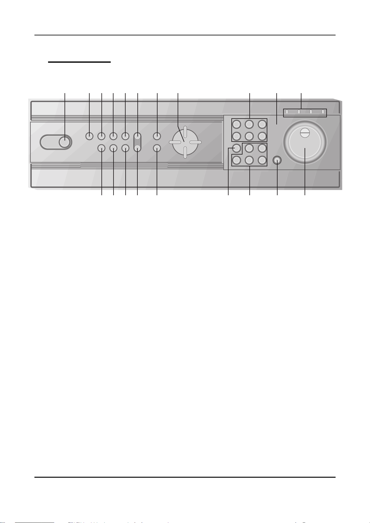
1. Front Panel Controls
1 2
3 4 5 9 12 14 1711 18
6 7 8 10 13 19 201615
1) POWER button
Press this button to turn the power on; press again to turn the power off. The POWER
LED (red) lights/goes off when the power is on/off. It flashes when switching during
initializing and disk checking.
2) LOCK button
Press this button to lock all unit’s key buttons including the remote controller.
The LOCK LED (green) lights/goes off when the lock is on/off. To release press it
again and enter the password.
3) RESTORE button
Press this button to restore recorded data to the main hard disk from an archive
device only when an external USB DAT24 is connected.
4) SCHEDULE button
Press this button to make scheduled recording standby. The SCHEDULE LED (green)
lights/goes off when the schedule is on/off.
5) INFO button
Press the button to display current system information; press again to display log list.
6) BACKUP button
Press this button to begin making a backup copy of the hard drive. If there is no
peripheral recording device connected, this button cannot be used.
7) PAN/TILT/ZOOM button
Press this button to control a PAN/TILT/ZOOM camera via RS-232 connection.
8) ZOOM button
Press this button to display zoom area box; press again to enlarge the image.
6
DIGITAL VIDEO RECORDER
Page 7

Pressing cursors can move this zoom area.
9) MENU button
Press this button to display the MAIN MENU screen.
It is also used as EXIT button to exit all kinds of OSD screen.
10) CLEAR button.
In Zoom mode, pressing this button reduces the image.
In stop mode and playback mode, pressing this button disappears time & date OSD.
Pressing it again appears the OSD.
On ‘RECORD GROUP SET’ menu, it sets each channel ‘Motion Detection’.
11) Direction ( €•ƒ„) buttons.
In Menu setup mode, used to move the cursor.
In Zoom mode, used to move the zoom area.
12) TIME SEARCH button
Press this button to display the Time Search menu.
13) ALARM SEARCH button
Press this button to display the Alarm Search menu.
14) Numeric buttons (NO. 1~9)
Used to enter the password and select the camera numbers.
15) Quad/Sequence, 0 button
Press this button to display the cameras in quad mode or to switch sequence function.
In addition, this button can be used as number 0 to set the password.
16) AUDIO PB button
Press this button to synchronize the sound track with the scenes.
17) Remote control signal receiver.
18) Mode Indicator.
19) SHUTTLE HOLD button
This button retains the selected playback or reverse playback speed.
Rotate the SHUTTLE ring to the desired search speed, and then press the SHUTTLE
HOLD button while holding the SHUTTLE ring at the selected search speed. Search
speed will be maintained even when the SHUTTLE ring is returned to its original
position.
20) Jog and shuttle operation
SHUTTLE ring
Use the ring to set various menus and search functions, to adjust the playback speed,
and to rewind or forward the image.
JOG dial
Use the dial to set various menus and search functions, and to forward or reverse the
image during playback (field-by-field).
7
DIGITAL VIDEO RECORDER
Page 8
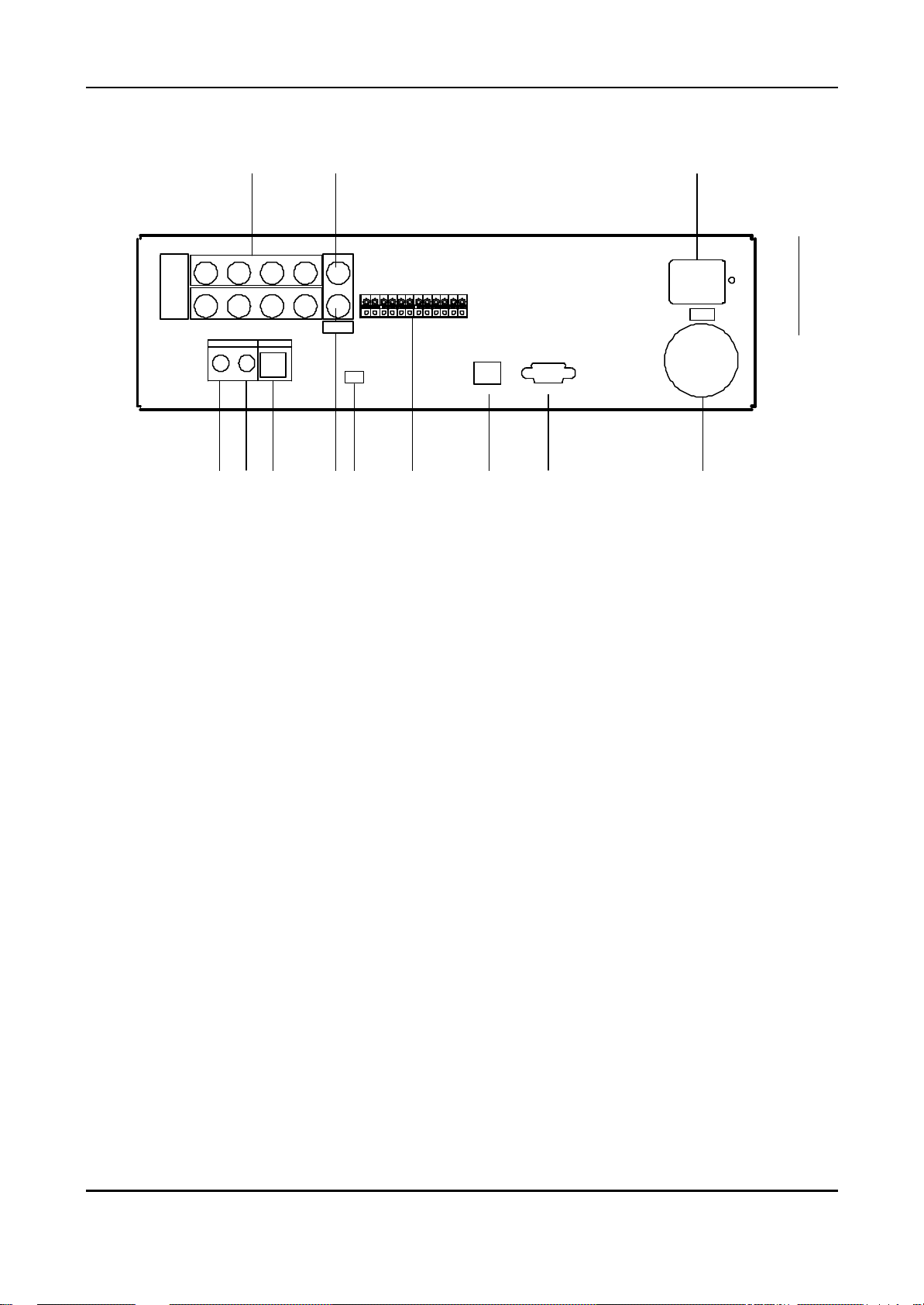
2. Rear Panel Connectors
1 2
CAMERA
IN
2 3
516 7
AUDIO MIC
INOUT
4 COMPOSITE
S-VIDEO8
VIDEO OUT
ALARM IN1
ALARM IN2
ALARM IN3
ALARM IN4
GND
ALARM IN5
ALARM IN6
ALARM IN7
ALARM IN8
GND
ALARM OUTPUT
GND
USB
ETHERNET RS-232C
63 4 5 7 8 9 10
1) CAMERA IN connectors
These are BNC input connectors for 8 cameras
2) VIDEO OUT connectors
A BNC standard composite video output connector
AC IN
100V 230V
11
12
3) AUDIO OUT connector
This is an RCA output for an audio signal.
4) AUDIO IN connector
This is an RCA input for an audio signal.
5) MIC jack
This is an input connector for a microphone.
6) S-VHS OUT connector
An S-VHS connector for separate luminance and chrominance (Y/C) signals This is
an RCA input connector for an audio signal.
7) USB 2.0 connector
This connector is for peripheral recording device.
8) ALARM IN/OUT terminal.
9) RJ-45 ETHERNET connector
10) RS-232C
11) AC power socket
12) Power Fan
8
DIGITAL VIDEO RECORDER
Page 9
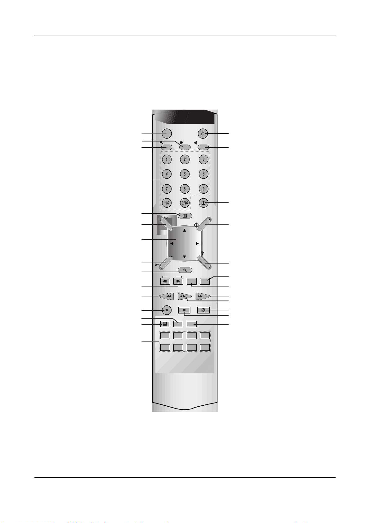
3. Remote Controller
Option (Not used)
Pan/Tilt/Zoom
Zoom AUDIO-PB
Number/Letter
MENU
ENTER
CURSOR
TIME SEARCH
LIST SEARCH
Field by Field
REW
REC
LOG
SYSTEM INFORMATION
Option (Not used)
DVR ID
ZOOM
-._
PQR
R
EA
S
-
T
REC
INFO LOG ALARM
F1 F2 F3 F4
F5 F6 F7 F8
ENTER
CH
STEP
REW
P/T/Z
ABC DEF
YZ@
MENU
L-SEARCH
BACKUP RESTORE
PLAY FF
STOP TIMER
STANDBY/ON
AUDIO-PB
MNOJKLGHI
VWXSTU
DISPLAY
L
E
C
N
A
C
A
-
S
E
A
RC
H
POWER
DISPLAY/QUAD
CANCEL
ALARM SEARCH
RESTORE
BACKUP
FF
PLAYBACK
TIMER
STOP
ALARM NOISE OFF
9
DIGITAL VIDEO RECORDER
Page 10
Ⅱ Installation & Connections.
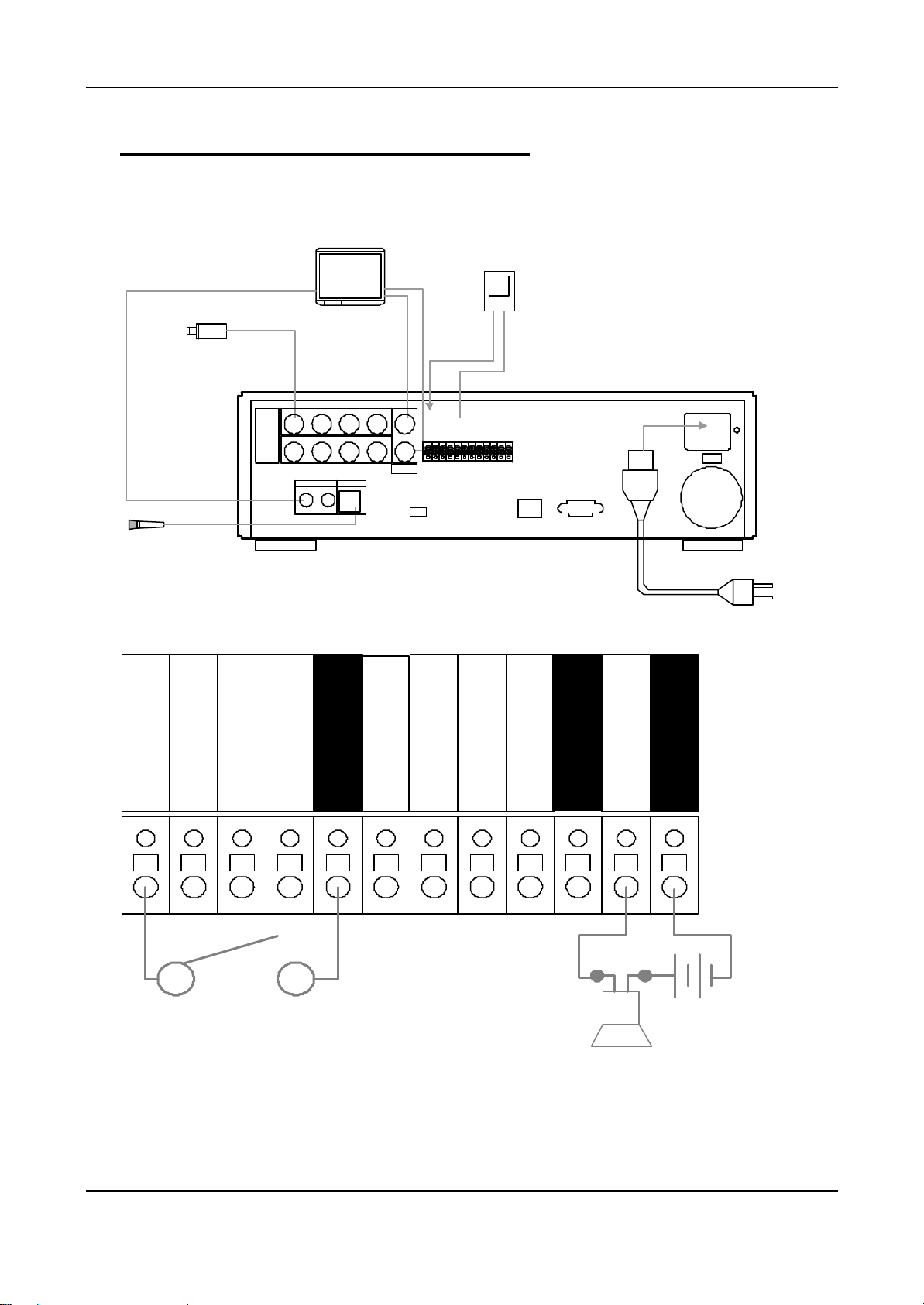
1. Camera, Monitor, Microphone, Alarm sensor and Power cord.
MONITOR
SENSOR#1
CAMERA#1
AUDIO OUT
MIC IN
MICROPHONE
Up to 8 cameras
CAMERA
IN
2 3
516 7
AUDIO MIC
INOUT
VIDEO OUT
or
S-VIDEO OUT
4 COMPOSITE
VIDEO OUT
AL ARM IN1
S-VIDEO8
USB
2. Alarm inputs and Alarm outs.
ALARM IN
AL ARM IN2
AL ARM IN3
AL ARM IN4
GN D
GND
AL ARM IN5
AL ARM IN6
AL ARM IN7
AL ARM IN8
GN D
AL ARM OUT PU T
GN D
ETHERNET RS-232C
POWER CORD
ALARM IN1
ALARM IN2
ALARM IN3
ALARM IN4
GND
± Connection of N.O (Normally Open)
ALARM IN6
ALARM IN5
ALARM IN7
ALARM IN8
GND
ALARM OUTPUT
GND
10
DIGITAL VIDEO RECORDER
Page 11
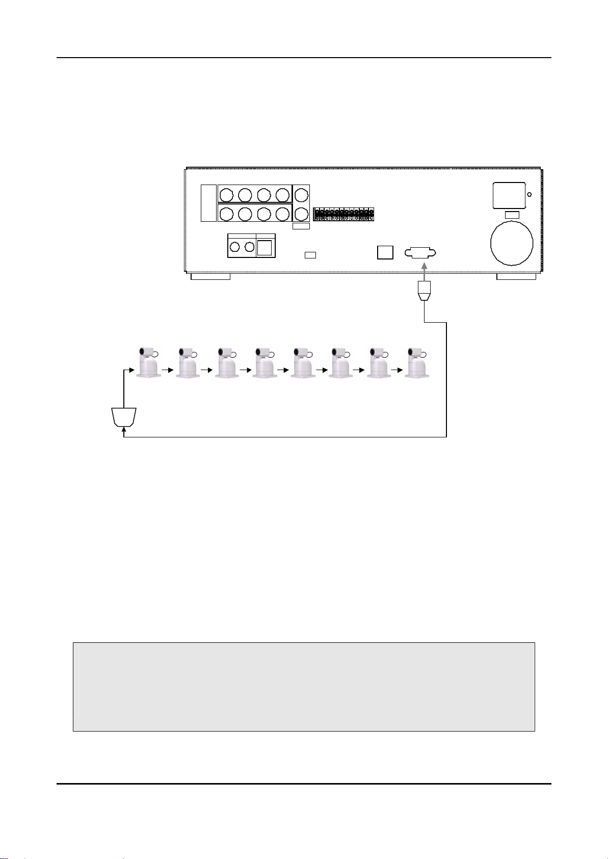
3. PAN/TILT/ZOOM Camera
1) C&B Technology (Model: PTZ102)
2) The other models: as buyers request; the camera sample and protocol should be
supported.
CAMERA
IN
2 3
516 7
AUDIO MIC
IN
OUT
4 COMPOSITE
S-VIDEO8
VIDEO OUT
A LARM IN 1
A LARM IN 2
A LARM IN 3
A LARM IN 4
G ND
A LARM IN 5
A LARM IN 6
A LARM IN 7
A LARM IN 8
G ND
A LARM OU TPUT
G ND
USB
ETHERNET RS-232C
PTZ CAMERA
CAM1 CAM2 CAM3 CAM4
CAM5 CAM6 CAM7
CAM8
CONTROL LINE
RS485 to RS232C Converter
4. PC system requirement for Network connection.
(a) 500MHz CPU
(b) 128MB RAM
(c) 4MB Video Card
(d) Windows 98SE, 2000, ME
(e) Spare 10/100-BaseT Ethernet Port
(f) RJ-45 Network Cable
NOTE:
We do not guarantee for all kind of PC even though the PC meets the
specification.
11
DIGITAL VIDEO RECORDER
Page 12
Ⅲ Operation
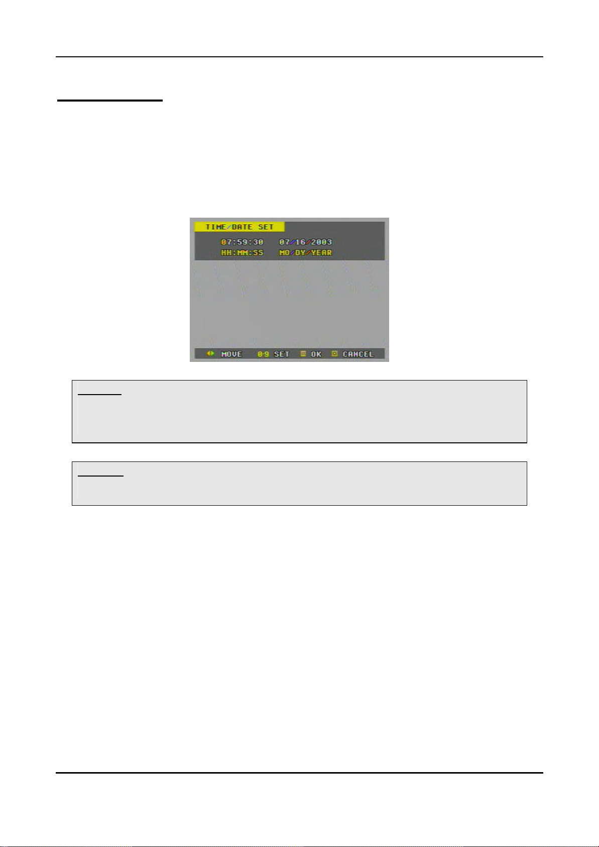
1. Time / Date Setting
1) When the DVR is turned on, ‘TIME/DATE SET’ menu appears after initializing.
2) Then enter Time & Date with numeric buttons (0-9).
3) After that, press the “Menu” button to set-up and exit.
<**> Note: There is a rechargeable battery inside the DVR to keep the DVR’s setting information.
The battery needs to be recharge at least 6 hours when the DVR is installed. The battery
would keep the setting information for 10 days if there is a power failure.
<**> Note: Factory default password is “000000”. It is recommended to change the “Password”
when you install the DVR. See the 30 page
2. Screen Position Adjustment.
While live view or playback, press the direction (€•ƒ„) buttons.
€ : The screen moves downward.
• : The screen moves upward.
ƒ : The screen moves left.
„ : The screen moves right.
12
DIGITAL VIDEO RECORDER
Page 13
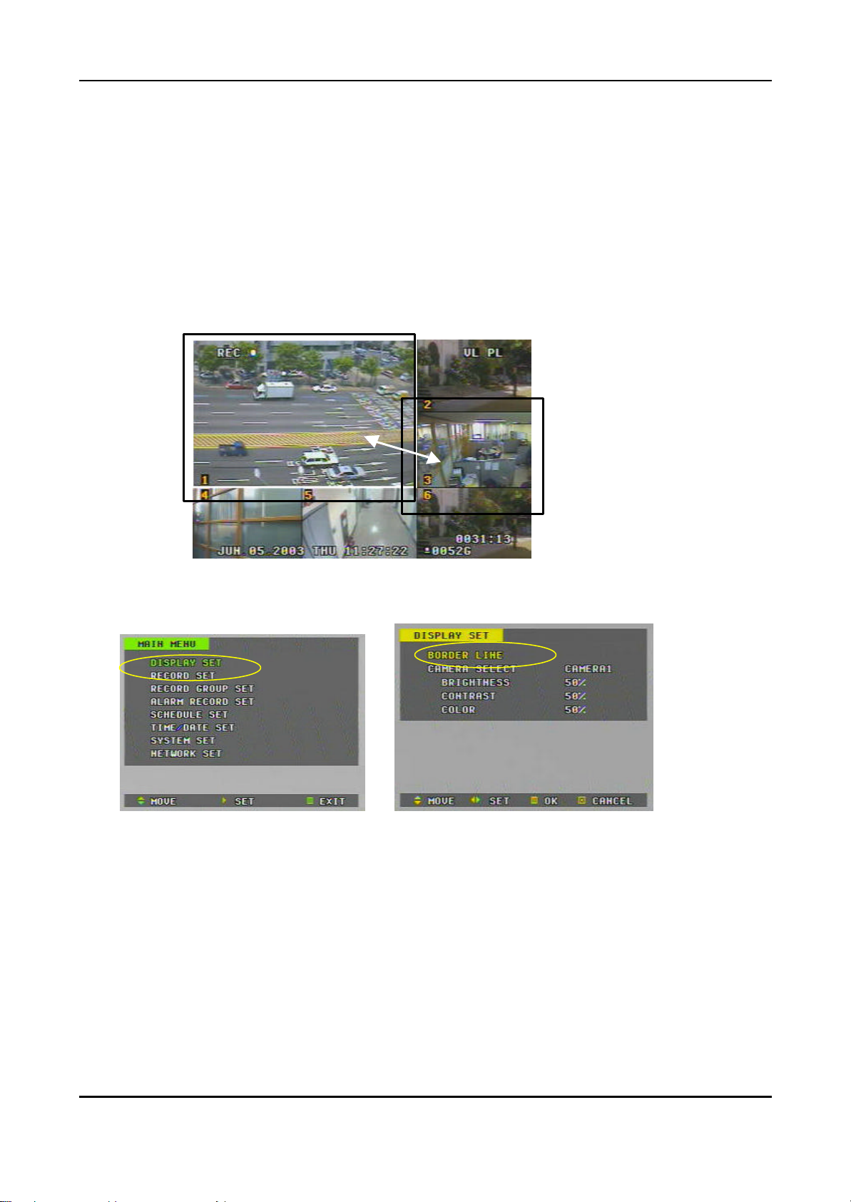
3. Live View
1) Live view mode switching
number.
Press the ‘QUAD’ (田口) Button to switch display modes
: 9 à 6à8 à Quad
To switch one of small view to main view on 6 or 8 channel display mode
- Press the “NO 9” button.
- While the boarder line of CH1(main) flashes press the desired channel
2) Border Line Color
è
a. Press the “MENU” button to go in the “ MAIN MENU”
b. While the “DISPLAY SET” flashes press the„ button or turn the SHUTTLE
ring to the right to enter
c. Press the € button to move the cursor to the “BORDER LINE”.
d. Then, press the „ button to select a line color.
BLACK (default) ©ª DARK GRAY ©ª GRAY ©ª WHITE
13
DIGITAL VIDEO RECORDER
Page 14
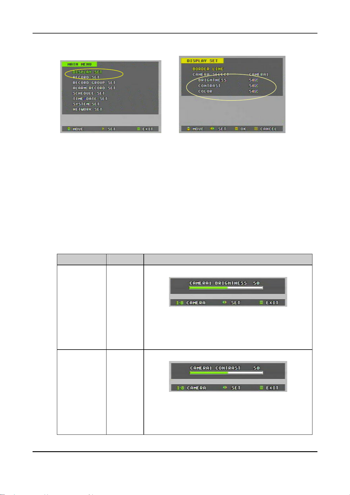
3) Brightness, Contrast & Color adjustment
è
a. Press the “MENU” button to go in the “ MAIN MENU”
b. While the “DISPLAY SET” flashes press the „ button or turn the SHUTTLE
ring to the right to enter
c. Press the € button to move the cursor to the “CAMERA SELECT”.
d. Then, press the „ button to select a desired camera.
CAM1 (default) ©ª CAM2 ©ª CAM3 ©ª CAM4©ª CAM5
©ª CAM6©ª CAM7©ª CAM8
e. After camera selection, press the € button to move the cursor down to the
“BRIGHT NESS”, “CONTRAST” or “COLOR”
f. Then, press the „ button to adjust.
ITEM DEFAULT ADJUTMENT
BRIGHTNESS
CONTRAST
50%
50%
- Camera number can be switched by pressing the number
buttons (1,2,3,~8 )
- The brightness of each camera can be adjusted by
pressing t u buttons or by turning the SHUTTLE ring
- Camera num ber can be switched by pressing the number
buttons (1,2,3~8)
- The contrast of each camera can be adjusted by pressing
t u buttons or by turning the SHUTTLE ring
14
DIGITAL VIDEO RECORDER
Page 15
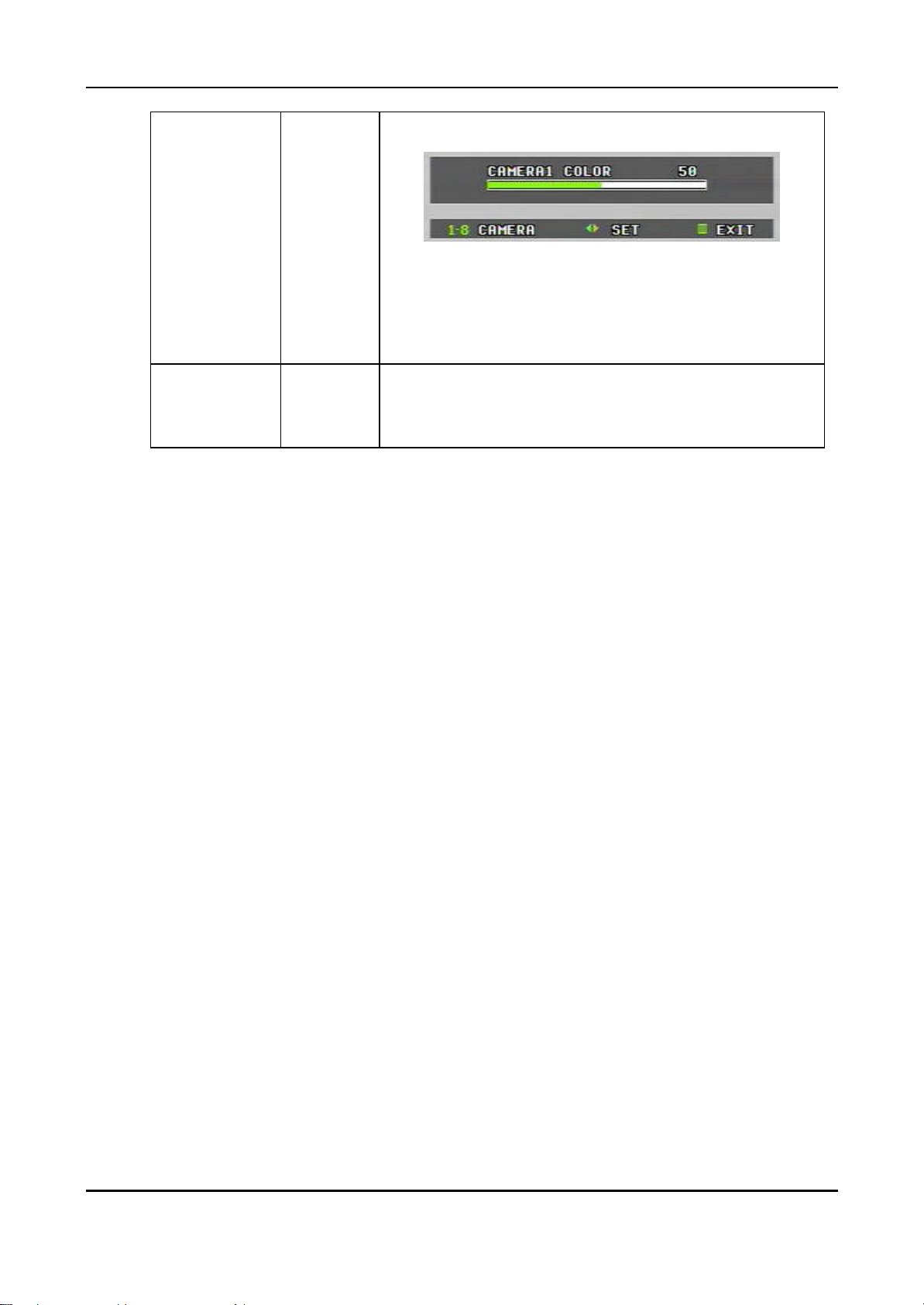
COLOR
SEQ. BYPASS
(Camera By
pass)
50%
NO
- Camera number can be switched by pressing the number
buttons (1,2,3~8)
- The contrast of each camera can be adjusted by pressing
t u buttons or by turning the SHUTTLE ring
YES, or NO
If the SEQ. BYPASS is YES, the selec ted camera will not be
shown in the sequential display mode.
To complete the setting and exit, press MENU button or SHUTTLE HOLD
button.
15
DIGITAL VIDEO RECORDER
Page 16
⇔
time recording (camera 1 & 2 or one of two cameras),
the others will not activate at all, even the network image transmission of
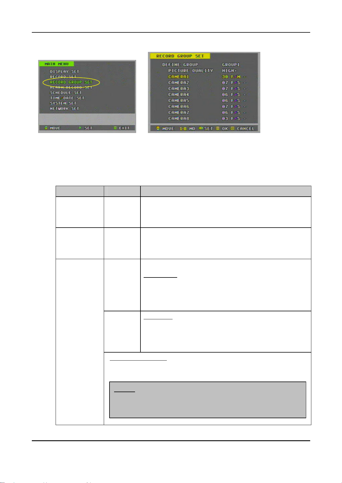
4. Basic Recording.
1) Press the “MENU” button to go into the “ MAIN MENU”
2) Press the € button to move the cursor to the “RECORD GROUP SET”
3) While the “RECORD GROUP SET” flashes press the„ button or turn the
SHUTTLE ring to the right to enter
4) Then, set the picture quality and recording rate of each camera.
ITEM DEFAULT ADJUTMENT
DIFINE GROUP
GROUP1
è
Up to 4 different recording modes (GROUP) can be predetermined.
GROUP1
GROUP2⇔GROUP3⇔GROUP4
PICTURE
QUALITY
CAMERA1 ~
CAMERA 8
HIGH+
3F/S
4F/S
Real-Time Recording
If you wish to record in real -time mode, set only camera 1 & camera 2.
NTSC: 30F/S, PAL: 25F/S
<Note> when real-
Select the picture quality
SUPER+ ©ª SUPER ©ªHIGH+ ©ª HIGH ©ª
MID+ ©ª MID ©ª LOW+ ©ª LOW
Select the capture rate of each camera.
NTSC setting
30F/S©ª15F/S©ª10F/S©ª7F/S©ª6F/S ©ª5F/S©ª4F/S
©ª3F/S©ª2F/S©ª1F/S ©ª30F/M (minute) ©ª20F/M©
ª12F/M©ª6F/M©ª4F/M©ª3F/M©ª2F/M©ª1F/M©ª00F/S
PAL setting
25F/S©ª12F/S©ª10F/S©ª7F/S ©ª6F/S©ª5F/S©ª4F/S
©ª2F/S©ª3F/S©ª1F/S©ª30F/M(minute)©ª20F/M©ª12F/
M©ª6F/M©ª4F/M ©ª3F/M©ª2F/M©ª01F/M©ª00F/S
the camera 3 ~8.
16
DIGITAL VIDEO RECORDER
Page 17
CH1 1-30 1-15 1-10 1-7 0 CH2 1-30 1-15 1-10 1-7 0 CH3 X 1-15 1-10 1-7 0 CH4 X 1-15 1-10 1-7 0 CH5 X X 1-10 1-7 0 CH6 X X 1-10 1-7 0 CH7 X X X 1-7 0 CH8 X X X 1-7 0
/S,
<Note> Recording Speed setting.
① NTSC 30F/S(PAL: 25F/S) : Only for Channel 1 and 2.
If you select the real-time recording speed (NTSC: 30F
PAL: 25F/S), it automatically makes disable to record for the
rest channels 3~8.
②NTSC 15F/S(PAL: 12F/S) : It applies to Ch 1~Ch4.
③NTSC 10F/S(PAL: 10F/S) : It record 6 channels- Ch 1~Ch6.
c
Recording Speed (F/S)
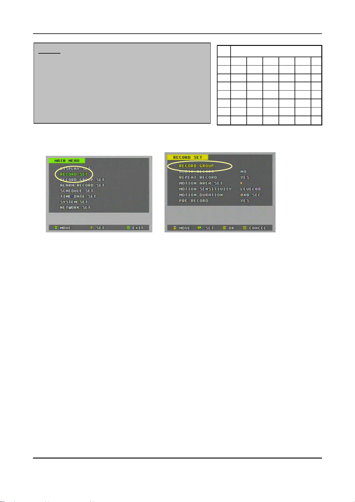
5) Press the “MENU” button to set up and go back to the “MAIN MENU”
è
6) Then, go into the “RECORD SET”
7) On the “RECORD GROUP”, select one of four Recording modes (Group) you
wish to record.
8) Select an audio recording source ( MIC or LINE) if audio is connected.
9) After that, press the “MENU” button to exit.
10) Press the REC button. Then, the red REC LED lights on the front panel and
recording starts.
11) To stop recording, pres the “ STOP” button.
17
DIGITAL VIDEO RECORDER
Page 18
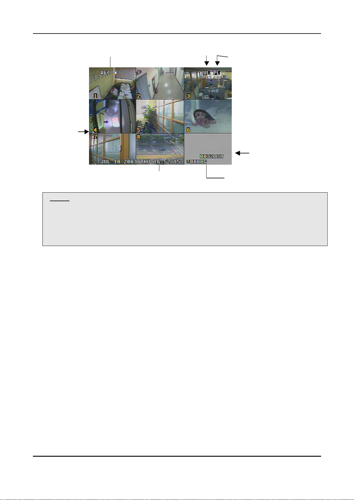
Current Recording Channels
: Turn to Yellow color
<Note>Estimated Recording Time varies due to picture quality and capture rate and is updated every
20 seconds due to variation of picture size.
When REPEAT RECORD is NO;
Indicate there is Video Loss
Indicate there was Power Loss
Estimated Recording Time
Month, Date, Year, Day, Time Available HDD space
Estimated Recoding Time shows the time when HDD is reached to the end.
When REPEAT RECORD is YES; Estimated Recording Time shows overwriting time of whole HDD.
18
DIGITAL VIDEO RECORDER
Page 19
When an alarm signal is input, the recording mode
is changed to the SUPER+ picture quality and 7 F/S for the
alarm is cleared, the recording
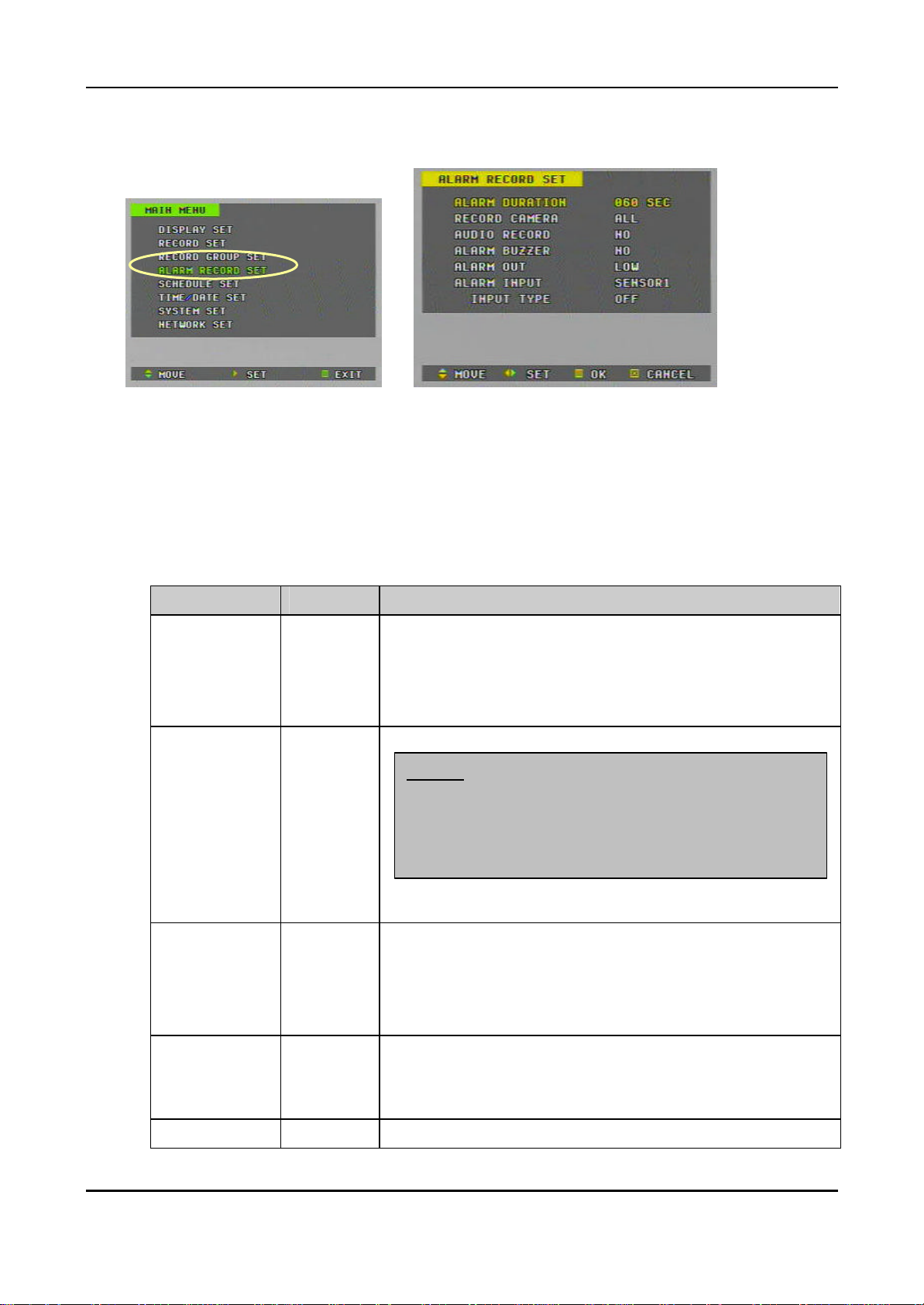
5. Alarm Recording
1) Press the “MENU” button to go into the “ MAIN MENU”
2) Press the € button to move the cursor to the “ALARM RECORD SET ”
3) While the “ALARM RECORD SET” flashes press the„ button or turn the
SHUTTLE ring to the right to enter.
è
4) Settings
ITEM DEFAULT ADJUTMENT
ALARM
DURATION
RECORD
CAMERA
AUDIO
RECORD
60SEC
ALL
NO
Determines the alarm recording duration after an input of
alarm signal.
20SEC ©ª 40SEC ©ª 60SEC©ª 80SEC ©ª 100SEC
©ª120SEC ©ª 180SEC ©ª 240SEC
- ALL: It records all channels when Alarm occurs.
<Note>
all cameras. When the
mode resumes to the previous recording mode.
- 1:1 : It records 1 channel by 1 alarm input. (SUPER+, 7 F/S)
Determines whether audio is recorded with images when an
alarm signal is input. It disregards the setting of audio recording
on the “RECORD SET
ALARM
BUZZER
ALARM OUT LOW LOW ( 0V) ©ª HIGH (5V)
NO
YES: The buzzer Sounds if an alarm is triggered.
NO: inactivates the ALARM BUZZER function.
NO©ª MIC ©ª LINE
Stops when the alarm recording stops.
19
DIGITAL VIDEO RECORDER
Page 20

ALARM INPUT SENSOR1
INPUT TYPE
OFF
Select a sensor you wish to determine input and output type of
the alarm.
SENSOR1 ©ª SENSOR2 ©ª SENSOR3 ©ª SENSOR4
SENSOR5 ©ª SENSOR6 ©ª SENSOR7 ©ª SENSOR8
OFF : Alarm recording OFF.
N.C (Normally Closed): Accepts alarm signals in the open state.
N.O (Normally Open): Accepts alarm signals in the closed state.
To complete the setting and exit, press MENU button or SHUTTLE HOLD button.
<Note> REC LED on the front panel flashes on the standby mode of Alarm recording.
5) Alarm recording starts when an ALARM IN terminal is triggered by an alarm
sensor.
6) If the unit receives a new alarm signal while in the alarm recording mode, the
alarm duration is recounted from the beginning.
7) When the alarm is cleared, the recording mode resumes to the previous
recording mode.
Alarm
recording mode
Shows there is an
alarm recording
20
DIGITAL VIDEO RECORDER
Page 21

6. PRE-Recording
1) Press the “MENU” button to go into the “ MAIN MENU”
2) Press the € button to move the cursor to the “RECORD SET”
3) While the “RECORD SET” flashes press the „ button or turn the SHUTTLE
ring to the right to enter
4) Press the € button to move the cursor to the “PRE-RECORD”
è
- When PRE- RECORD is YES; It records the most recent 140 images.
<Note> It applies to all recording types; Basic Recording, Alarm Recording, Motion
Recording, Schedule recording.
21
DIGITAL VIDEO RECORDER
Page 22

7. Schedule Recording (Timer Recording)
è è
** Before Schedule Table setting, you need to pre -determine 4 different recording modes (Group
1-4); refer “Basic Recording”
è è
1) Press the “MENU” button to go into the “ MAIN MENU”
2) Press the € button to move the cursor to the “SCHEDULE RECORD SET”
3) While the “SCHEDULE RECORD SET” flashes press the „ button or turn the
SHUTTLE ring to the right to enter.
4) To set the day, time and group, press the NUMERICAL button.
5) To move the cursor to the right/left, press the t u buttons or turn the SHUTTLE
ring.
6) To move the cursor up/down, press the p q buttons or turn the JOG dial.
Settings
ITEM
D/W
(Day of Week)
START - The time of recording start.
END - The time of recording end. The ending time must not be before
DEFAULT ADJUTMENT
-
Sunday: 1, Monday: 2, Tuesday:3, Wednesday: 4,
Thursday: 5, Friday: 6, Saturday:7. ALL : 8 (Every day)
the starting time or the same as the starting time. It must be any
time over the starting time.
22
DIGITAL VIDEO RECORDER
Page 23

MODE - NO : inactivate the recording.
GROUP1 ~ GROUP4 : select one of groups.
Deletion: To delete each line, select the MODE as ‘------‘ then
exit to menu. (Use No 6 button on Mode)
<Note> The recording time is set by 24H. You need to set 2 days if the setting is over one day.
The recording would not start when Ending time is ahead of Start time
To complete the setting and exit, press MENU button or SHUTTLE HOLD button.
<Note> REC LED on the front panel flashes on the standby mode of Schedule recording.
7) To activate the schedule recording after setting, press the SCHEDULE button.
The SCHEDULE indicator illuminates.
8) When a program covers the current time, the REC indicator illuminates and the
unit begins recording.
9) When the scheduled recording time is over, the REC indicator goes off and
recording stops.
10) If you wish to stop recording while scheduled recording, press the SCHDULE
button, then the SCHEDULE indicator goes off and the Schedule Recording
Mode is released.
Schedule
recording mode
23
DIGITAL VIDEO RECORDER
Page 24

8. Motion Detected Recording (MOTION RECORD)
è
1) Press the “MENU” button to go into the “ MAIN MENU”
2) Press the € button to move the cursor to the “RECORD SET”
3) While the “RECORD SET” flashes press the„ button or turn the SHUTTLE ring
to the right to enter
4) Press the € button to move the cursor to the “MOTION AREA SET”
5) While the “MOTION AREA SET” flashes press the„ button or turn the
SHUTTLE ring to the right to enter
è
6) Select a desired camera and press the„ button. Then, motion blocks are
appeared.
7) Select desired motion blocks by pressing numeric buttons.
8) Then, go back to the “RECORD SET” by pressing the MENU button.
è
9) Select the MOTION SENSITIVITY Level and duration
24
DIGITAL VIDEO RECORDER
Page 25

Motion detected recording
Motion sensitivity also varies upon on the number
MOTION
SENSITIVITY
ITEM DEFAULT ADJUTMENT
8
Level 1: Low sensitivity~ Level 15: High sensitivity
<Note>
of blocks you select
Recording
Duration
40 SEC Select recording duration when motion is detected
20 SEC– 40 SEC – 60 – 80 – 100 – 120 – 180 – 240 SEC
10) Go to the “RECORD GROUP SET”.
11) Press the channel button(s) you wish to activate ‘motion detected recording ’.
12) Then, ‘M’ is appeared next ‘F/S’.
13) To complete the setting and exit, press MENU button or SHUTTLE HOLD button.
mode
* Motion Detected channel flashes and turns to yellow color when it starts recording.
Note> REC LED on the front panel flashes on the standby mode of Motion recording.
Note: There may be cases when the recorder’s built-in motion detection function does not
operate properly due to the condition of the input video signal or other factors.
Note: It is recommended selection of at least 3 motion blocks to get more accurate motion
recording.
Note: Each channel starts motion recording separately with time interval upon on the motion
detected.
25
DIGITAL VIDEO RECORDER
Page 26

① ② ③④⑤⑥
9. TIME SEARCH – Time and Date Search
Note: If an external USB HDD is connected to the DVR, choose which HDD you want to search on
the SYSTEM SET menu (à BACKUP SET à PLAYBACK HDD à Internal HDD or External
HDD)
1) Press the TIME SEARCH button to display the TIME SEARCH menu.
① Hours in 24 hour mode (0 ~ 24)
② Month and Date where recorded data file exists.
③ The colored bar means recorded time length. For example, the unit
recorded images from 15:00 on March 02.
④ Black area means there is no data file recorded. For example, the unit did
not recorded images from 03:00 – 24:00 on Jan 01.
⑤ Press the t, u buttons to move the cursor to indicate time zone you wish
to search.
⑥ Press the p, q buttons to move the cursor to indicate month and date you
wish to search.
2) Each page displays up to 10 days. To go to the previous or next pages press
the p, q buttons or turn the JOG dial.
3) Press the TIME SEARCH (T-SEARCH) button again to search when the cursor
is reached to desired time and date.
Note: Time search will not be activated if the cursor is placed at black areas.
4) Then, on the next screen time files and Cameras are listed in a minute mode.
26
DIGITAL VIDEO RECORDER
Page 27

5) Place the cursor to the desired time you wish to play back using the p, q, t,
u buttons and then, press the PLAY or TIME SEARCH button to play back.
10. PLAYBACK
1) Basic Playback
a) Press the PLAY button while recording or in stop mode.
The oldest recording file on the hard disk is played back when you press the
PLAY button for the first time after the power is turned on.
After the first time, subsequent pressing of the PLAY button will resume
playback from the point where it was stopped.
b) To switch the camera, press the desired camera number while playback.
To switch display mode, press the Quad (田) button while playback.
To switch one of small view to main view on 6 or 8 channel playback mode.
- Press the “NO 9” button.
- While the boarder line of CH1(main) flashes press the desired channel
number.
c) When the end of HDD is reached while playback, playback continues from
the beginning of HDD.
d) Press the STOP button to stop playback. If the unit is recording while
playback, pressing the STOP button once stops only playback. Pressing the
STOP button twice stops recording.
27
DIGITAL VIDEO RECORDER
Page 28

In Playback Mode Playing back audio
Current Channel
2) Reverse Playback
(a) Press the PLAY button again while playback. The unit begins reverse
playback.
(b) To resume playback press the PLAY button again.
3) Field by field (Still field) Playback
a) Press the STILL button during playback. The unit shifts in to still-field mode.
b) JOG dial;
Turn the JOG dial in either direction during still -field playback.
Turn the JOG dial one stop to the right to move forward one field and one
stop to the left to move back one field. Continue turning the JOG dial to the
Playing back Alarm Recording
right for forward playback of consecutive fields and to the left for reverse
playback of consecutive frames. Stop turning the dial for still -field viewing.
c) Remote controller;
Press the forward step button ( ) to move forward field by field (picture by
picture).
Press the reverse step button ( ) to move reverse field by field.
Forward still-field playback Reverse still-field playback
28
DIGITAL VIDEO RECORDER
Page 29

①
②
③
④
⑤
4) Adjusting Playback Speed
a) SHUTTLE ring;
The SHUTTLE ring can be used to adjust the playback speed. Playback speed
will vary according to how far the SHUTTLE ring is turned.
REVERSE
②
①
16
③
8
④
4
2
⑤
STILL
⑥
2
FORWARD
⑦
4
⑧
8
16
⑨
Reverse speed search (X speed) ⑥ Forward speed search (2X speed)
Reverse speed search (8X speed) ⑦ Forward speed search (4X speed)
Reverse speed search (4X speed) ⑧ Forward speed search (8X speed)
Reverse speed search (2X speed) ⑨ Forward speed search (16X speed)
Regular or still-field playback
b) Remote Controller
Playback speed will vary by pressing the fast forward button ( ) or the fast
reverse button ( ).
: ▷ ž▷▷ž▷▷▷ž▷▷▷▷ž▷▷▷▷▷
: ◁ ž◁◁ž◁◁◁ž◁◁◁◁ž◁◁◁◁◁
c) SHUTTLE HOLD
Rotate the SHUTTLE ring to the desired search speed, and then press the
SHUTTLE HOLD button while holding the SHUTTLE ring at the selected
search speed. Search speed will be maintained even when the SHUTTLE ring
is returned to its original position.
d) To resume playback while forward or reverse speed search press the PLAY
button.
29
DIGITAL VIDEO RECORDER
Page 30

5) Audio playback (AUDIO-PB)
a) Image recording varies as capture rate set. Howe ver, audio is recorded in
real-time always. Therefore, in playback mode audio may not be played
properly depending on recorded field rate.
b) While playback press the AUDIO-PB button to synchronize the sound track
with the scenes.
<Note> The audio playback may not be performed properly in the real-time recording & real-
time playback mode.
11. ALARM / MOTION – Alarm List Search
1) Press the ALARM SEARCH (A-SEARCH) button to display the alarm-recording list.
(‘AL’ means Alarm and ‘MO’ means Motion).
2) Press the p,q buttons or turn the JOG dial to move the cursor to the desired
alarm-recording file.
3) Press the PLAY or ALARM SEARCH (A-SEARCH) button to play back.
4) Each page displays up to 10-alarm list. To go to the previous or next pages
press the ◀▶ buttons or turn the JOG dial
30
DIGITAL VIDEO RECORDER
Page 31

12. SYSTEM SET
1) Press the MENU button or SHUTTLE HOLD button to display the MAIN MENU.
And then, go to the SYSTEM SET using pq buttons or the JOG dial.
2) Press the u button or turn the SHUTTLE ring to the right while the SYSTEM
SET flashes. The SYSTEM SET sub-menu appears.
ITEM DEFAULT ADJUTMENT
PASSWORD
000000
è
– Changing the password
a) Press the u button or turn the SHUTTLE ring to the right while
DISK FORMAT
the PASSWORD flashes. Then the CURRENT PASSWORD setting
appears. Enter your current password using numeric buttons from 0
to 9.
b) Enter the new password using the numeric buttons from 0 to 9.
c) Enter the new password to confirm. Then the password is
changed.
-
– Formatting internal HDD
a) Press the u button or turn the SHUTTLE ring to the right while
the DISK FORMAT flashes. Then, “DO YOU REALLY WANT TO
FORMAT?” message appears.
b) Press the MENU button to format the disk.
Press the CLEAR button to cancel.
31
DIGITAL VIDEO RECORDER
Page 32

**Important: If you wish to format the HDD while using, please follow the steps below.
1. Stop the DVR completely and power off.
2. Restart the unit.
3. Format the HDD on the SYSETM SET menu.
4. After that, restart the unit again.
Then, HDD formatting is completed.
3) BACKUP SET
ITEM DEFAULT ADJUTMENT
USB DISK
FORMAT
-
Formatting external back up device.
<*Exactly same procedures as formatting of internal HDD>
① Press the u button or turn the SHUTTLE ring to the right while
the DISK FORMAT flashes.
② Then, “DO YOU REALLY WANT TO FORMAT?” message
appears.
③ Press the MENU button to format the disk.
Press the CLEAR button to cancel.
**Important: If you wish to format the USB DISK while
using, please follow the steps below.
1. Stop the DVR completely and power off.
2. Restart the unit.
3. Format the USB DISK on the SYSETM SET menu.
4. After that, restart the unit again.
④ Then, HDD formatting is completed.
32
DIGITAL VIDEO RECORDER
Page 33

Note: This menu will not be selected if there is no external USB device connected.
ITEM DEFAULT ADJUTMENT
BACK UP
MODE
PLAY BACK
DISK.
MANUAL - MANUAL: The recorded data within a certain time range can be
INTERNAL
4) AUTO KEY LOCK
YES: All key buttons are locked automatically if there is no button
pressed in 3 minute.
NO: inactivates the Auto Key Lock function.
<NOTE> In the case of entering Main Menu and RECORD STOP, it
automatically locked even though you choose “NO” for Auto Lock
5) KEY BUZZER
back up to the peripheral storage only when the BACKUP
button is pressed.
- AUTO: Backups of previously recorded data are made at the same
time the DVR is recording new data.
Choose which HDD you want to search and playback when an external
USB device is connected.
INTERNAL ßà EXTERNAL
YES: Whenever any button is pressed there is a beep sound shortly.
NO: inactivates the KEY BUZZER function.
6) PAN/TILT/ZOOM model number
Enter the PAN/TILT/ZOOM camera ID connected currently (00~99).
33
DIGITAL VIDEO RECORDER
Page 34

<ID List>
ID No
00 C&B Tech CNB-PTZ102
01 Merit Lilin Ent PIH-7000/7600
02 VCL Orbiter Microsphere
03 SAMSUNG SCC641
04 NEC NC-21D
05 SUNKWANG SK2107
06
07 SUNIN /WONWOO PT-101
08 LPT A100 (LG) P/T/Z
09 HONEYWELL GC-655N
10
11 PELCO D-PROTOCOL :2400bps
12 PELCO D-PROTOCOL :4800bps
13 PELCO D-PROTOCOL :9600bps
14
Manufacturer Model Name
15 CANON VC-04
34
DIGITAL VIDEO RECORDER
Page 35

13. NETWORK SET
1) LAN CONNECT
-Connect LAN Cable to Ethernet Port on the Rear.
2) Set UP IP Address
è è
è
A. Press the MENU button or SHUTTLE HOLD button to display the MAIN
MENU. And then, go to the NETWORK SET using pq buttons or the JOG
dial.
B. Press the u button or turn the SHUTTLE ring to the right while the NETWORK
SET flashes. The NETWORK SET sub-menu appears.
C. Press the p q buttons or turn the JOG dial to move to the desired item, and
then press the Numeric buttons to set the IP ADDRESS, NETMASK and
GATEWAY.
D. To complete the setting and exit, press MENU button or SHUTTLE HOLD
button.
35
DIGITAL VIDEO RECORDER
Page 36

14. Information & Log List
1) Information
a) Press the INFO button on the front panel of unit or on the remote
controller to display.
b) It shows current recording information.
c) To exit press the MENU button.
2) LOG LIST
a) Press the INF O button twice to display the log list
b) It displays up to 4 pages and each page displays up to 10 lists.
To show the previous or next pages press the p, q buttons.
c) Press the MENU button to exit.
36
DIGITAL VIDEO RECORDER
Page 37

15. ZOOM
Note: The ZOOM button is not activated when a menu is displayed on the screen.
1) Press the ZOOM button to display the Zoom Area Box.
2) Move the box to the desired position using the p, q, t and u buttons.
3) Press the ZOOM button to enlarge the desired area.
4) Press the CLEAR button to exit.
<Note> It only works for Full Channel view.
16. PAN/TILT/ZOOM Camera control
1) After connection of P/T/Z cameras, press the P/T/Z button on the front panel or
the remote controller. Then, P/TZ control mode appears as the picture below
<Picture1>.
<Picture1> Manual Pan/Tilt/Zoom control mode. <Picture2> Auto Pan/Tilt/Zoom control mode.
2) PAN control: Press t or u button on the front panel or the remote controller.
TILT control: Press p or q button on the front panel or the remote controller.
ZOOM control: Press the T-SRCH (Time Search) button to zoom out or the A-
SRCH (Alarm Search) button to zoom in.
MENU button: Press to exit the mode.
3) Press PTZ button again, go to Auto Control <Picture2>.
37
DIGITAL VIDEO RECORDER
Page 38

17. External Backup Device control (USB DI SK type)
A. Auto external device detection.
1) Connect an external backup device to the DVR while DVR is in ‘STOP’
mode.
2) The DVR unit detects the external backup device automatically within 15
sec and the external backup device icon appears on the monitor screen.
B. Backing up data (AUTO or MANUAL mode)
1) When the BACKUP mode on the SYSTEM SET menu is set as AUTO;
Press the BACKUP button on the front panel or remote controller, then,
an arrow (u), direction to the right, appears and the unit starts
backing up to the external device from the beginning of the HDD
2) To stop backing up, press the BACKUP button again. Then, the arrow
(u) starts flashing while the archiving process is halted. The arrow (u)
goes off at the end of the process, and the next backup recording will
begin at this point.
3) When the BACKUP mode on the SYSTEM SET menu is set as
MANUAL; Press the BACKUP button, then the BACKUP TIME SET
mode appears as picture below.
4) Now, set the starting and ending times. Within the time range, there
should be recorded data exist in the main hard disk drive.
5) Press the BACKUP button after the setting. Then, the arrow (u) appears
and backup recording within the time range is started.
38
DIGITAL VIDEO RECORDER
Page 39

C. When a CD-RW is connected.
1) Set the BACK UP mode as MANUAL on the SYSTEM SET menu.
è
è
2) Exit the menu.
3) Press the BACKUP button, then the BACKUP TIME SET mode appears
as picture below.
3) Now, set the start ing and ending times. The ending time must not be before
the starting time or the same as the starting time. It must be any time over
the starting time.
4) Press the BACKUP button after the setting. Then, the DVR detects the size
of CD and starts to copy with an arrow (u) appearing. 6) The arrow (u)
goes off after back up.
Note: It is saved as “image” file format.
39
DIGITAL VIDEO RECORDER
Page 40

D. Backup Search (Time-Search, Alarm-Search, Playback)
- When an External USB HDD is connected.
è
è
1) Press the MENU button and go to the SYSTEM SET menu.
2) Then, go to the ‘BACK UP SET’.
3) Select as EXTERANAL on the PLAYBACK DISK menu.
4) Press the MENU button to exit the menu.
5) After that, the external USB DISK can be controlled like the internal
HDD. (Time Search, Alarm Search, Playback)
Note: It is possible that some USB devices from different venders may not be
compatible.
40
DIGITAL VIDEO RECORDER
Page 41

Ⅳ
Client Program
1. How to install and connect
(1) Installation– it is automatically downloaded when you access to DVR.
A. Enter the DVR IP address. Then ‘ActiveX control’ window appears. Click ‘Yes’.
- or the Client S/W can be installed with the CD enclosed.
B. ‘ActiveX control’ is installed and connection window appears.
C. Enter the password of DVR and click the ‘Connect’ button.
41
DIGITAL VIDEO RECORDER
Page 42

(2) Installation By CD.
A. Insert “Network Software CD” to CD-ROM of your PC and Find “SETUP.EXE”
B. Double Click “SETUP. EXE”
C. Click “Install”
D. Click 「Close」Button after below images appears.
E. The ICON of DVR LOCAL PLAYER 」will be displayed on your PC.
42
DIGITAL VIDEO RECORDER
Page 43

2. Features
(1) Main Screen
(A)
(B)
(2) Tool Bar
(C)
(A): Tool bar; - control buttons
(B): Main View – Live.
(C): Current DVR Status.
(A)
(E)
(B) (C) (D)
(F)
u (A)
n Client Setup:
1) Web Client Version Check
2) Live Record Set up: Select Live Record file Size and Save Place
n DVR Setting: Click to change the DVR setting.
u (B) File Manager: Click to down load the image files from the DVR.
43
DIGITAL VIDEO RECORDER
Page 44

u (C)
n PRINT: Click to print the current still image.
n Live Record: Click to record the current live images.
u (D)
n PTZ Camera : PAN/ TILE/ZOOM control button.
n PLAYER: Local player; click to playback the images file
downloaded from the DVR server.
n OSD ON/ OFF: OSD(On Screen Display on /off)
u (E) Camera Display buttons
n Multi View: Click to view in different view mode.
n 1 ~ 8 : Click to zoom in each camera.
u (F) Selection of LIVE Picture Quality.
n HIGH: 720 x 486
n MID: 360 x 243
n LOW: 180 x 122
(3) Status Bar
(A) (B) (C) (D)
u (A): Current DVR Status (Time and Date, Power On / REC / PLAY / STOP / etc..)
u (B): SCHEDULE Recording ON/OFF status
u (C): Manual LOCK ON/OFF
u (D): Remain HDD capacity of internal storage and external storage.
44
DIGITAL VIDEO RECORDER
Page 45

3. Image file down load from the DVR server.
(1) Click the ‘File Manager’ button on the tool bar
(2) Then, the image file list appears.
(3) Select one of the files you wish to down load.
u Preview: Click to preview the images without downloading. Press Stop button to
stop preview.(It automatically stopped when preview is done)
<note> You need to select again, if you stop “preview” while it is working.
u Download : Downloading without preview.
(4) Example
45
DIGITAL VIDEO RECORDER
Page 46

4. DVR Setting
(1) Click the ‘SETUP’ button on the Tool bar
(2) DVR Setting: To change the DVR setting, enter the supervisor password.
<Note> Password: It is different from the DVR’s password. It is a network
password for supervisor to allow changing DVR setting from the remote place via
network connection. Default :000000
(3) DVR Setting (General)
-‘DVR Setting Dialog’ window appears when you enter the proper password.
46
DIGITAL VIDEO RECORDER
Page 47

u DVR Control
n REC: DVR recording ON
n STOP: DVR recording STOP
n SCHEDULE ON: Schedule recording ON/OFF
u Supervisor Password Management (Network password)
n New Password
n Confirming the New Password
(4) DVR SETUP (Camera)
CAM 1 ~ 8: Camera selection.
Brightness: 0 ~ 99
Contrast: 0 ~ 99
Color : 0 ~ 99
47
DIGITAL VIDEO RECORDER
Page 48

motion level
Recording
(5) DVR SETUP (Record Setting)
GROUP 1 ~ 4:
Recording Group selection.
Audio Recording selection
Repeat Recording on / off.
Motion Sensitivity:
setting.
(6) DVR SETUP (Record-group setting)
Group selection: 1 – 4
QUALITY: Picture quality
Camera 1 ~ 8:
speed of each camera.
Motion detection: ON/OFF
48
DIGITAL VIDEO RECORDER
Page 49

start recording of all
alarms
1:1 Camera: If alarm No.1 is triggered,
AUDIO RECORD: Audio recording
(7) DVR SETUP (alarm-recording setting)
Alarm Duration: 20~240 Sec
REOCRD CAMERA
All Camera:
when any of 4
.
on/off
ALARM BUZZER: alarm buzzer on/off
ALARM OUT : level
ALARM ONPUT: SELECT
(8) DVR SETUP (System setting)
INPUT TYPE : N.O, N.C, OFF
BACKUP MODE:
Backup mode setting (MANUAL /
AUTO)
PLAYBACK DISK : Selection.
49
DIGITAL VIDEO RECORDER
Page 50

5. Local Player
(1) Click the “Player” button on the tool bar to open ‘DVR Player’ window.
(2) Click the ‘Open’ button.
(3) Select an image file (.ADV or .ADB) and click ‘Open’ button.
50
DIGITAL VIDEO RECORDER
Page 51

(A)
(D)
(B)
(C)
(E) (G)
(F)
u (A) MAIN: Open, Print, Display of Video Type
u (B) Camera Selection .
u (C) Display of Picture quality
u (D) Display Mode
u (E) Save a snap image as JPEG., GIF , BMP or PNG
<note> It is saved as same as display mode which you are watching.
u (F) Operation Buttons
u (G) PRINT
51
DIGITAL VIDEO RECORDER
Page 52

Ⅵ How to connect modem
**<<Recommended external modem : US-ROBOTICS, Model ID: 5686>>
Please follow the next procedure after installed client software. We provide client software
in a CD.
1. Connect modem (US-Robotics) to the back of DVR RS-232C.
2. Follow the below steps:
Start ? Programs ? Accessories ? Communications ? Network and Dial-up
Connections
52
DIGITAL VIDEO RECORDER
Page 53

3. Double click “Make New Connection”.
4. Click “Next” at the window of network connection wizard.
53
DIGITAL VIDEO RECORDER
Page 54

5. Check “Dial-up to private network” and click “Next”.
6. Enter the telephone number, which is connected, to the DVR
54
DIGITAL VIDEO RECORDER
Page 55

7. Check “For all user” and click “Next”
8. Type DVR at the parameter, check “Add a shortcut to my desktop” and click “Finish”
55
DIGITAL VIDEO RECORDER
Page 56

9. Type “dvr” at the user name and enter the password(Six digits 000000 are initial
password) click “Dial”
10. You can find this window if connection is succeed and see the speed of this
connection at the bottom tool bar. To the next, Run Internet Explorer
The highest speed of analog modem is 33.6kbps between DVR and the
Computer. At the ISP(Internet Service Provider) and digital modem, It’s max
speed is 56kbps. Feel free to ask more information to the US-Robotics
56
DIGITAL VIDEO RECORDER
Page 57

11. Enter this IP address 192.168.0.60 and press Enter key.
12. You can find DVR Connect Dialogue if the program is installed successfully. And click
“Connect” button.
57
DIGITAL VIDEO RECORDER
Page 58

13. Enter this password (Six digits 000000 are initial password), click “Advance”, check
“Modem user” and click “Connect”.
14. You can see the picture if connected successfully.
58
DIGITAL VIDEO RECORDER
Page 59

15. To disconnect modem, place the cursor on the this Icon and right-click and click
“Disconnect”
16. To connect modem to the DVR, just double click the icon of DVR.
59
DIGITAL VIDEO RECORDER
Page 60

Ⅶ Specification & Contents
1. SPECIFICATION
Video Input 8 (NTSC/PAL)
Video Output 1 Monitor, 1 S-Video
Loop Out None
Live& Playback Display 1,4, 6,7,8,9, PIP
Compression WAVELET
Live Display Resolution NTSC 720*480, PAL 720*576
Record & Playback Resolution
Alarm In/Out 8/1
Operating System EMBEDDED LINUX
System Control Key buttons & Jog/Shuttle, IR Remote, Remote Client
Live Display Speed NTSC 240 fps, PAL 200 fps
Maximum Recording Speed 60 fps
Recording speed per Channel
Audio Record 1ch (1ch Line In/Out, MIC Input)
Display Brightness, Contrast, Color Adjustments Per Channel
Recording Mode Manual, Schedule, Alarm, Motion
Recording Method 8 Levels of Compression / Record Frame Rate Adjustment
Recording Adjustments Pre-Alarm: 140 frames / Post-Alarm: 20 sec. ~ 240 sec.
Motion Detection Per Channel
Search Mode Date& Time, Camera, Alarm / Motion
Playback Modes Forward & Reverse: Pause, Frame by Frame, Normal Speed, 2X, 4X, 6X, 8X
9 Selectable Grids / 15 Sensitivity Levels
NTSC 720*243, PAL 720*288
7.5 fps
Features
Multi-tasking / Full Triplex Simultaneous Live Display, Record, Playback, Remote Transmission
Watchdog Auto Reboot w/ Maintaining Previous Settings
System Utility Password /Auto Lock /Disk Format /Disk Check
Back Up Ethernet, Remote PC, External Recording Devices, VCR
External Recording Devices HDD, DAT, CD-RW
Interface USB, RS -232, Ethernet
HDD 80G Default (UPTO 2 INTERNAL HDDS)
Network LAN, WAN, Internet, PSTN Line
Remote Client Software Plug-In For Internet Explorer 6.0
IR Remote Yes
Dimension / Weight 360(W) x 340(D) x 100(H) / 6 Kg
60
DIGITAL VIDEO RECORDER
Page 61

2. Contents
CONTENTS QUANTITY REMARK
DIGITAL VIDEO RECORDER 1 UNIT
REMOTE CONTROLLER 1
BATTERY (AA size) 2
POWER CORD 1
INSTRUCTION MENUAL 1
61
DIGITAL VIDEO RECORDER
 Loading...