

Daewoo DWM-900C, DWM-800CP, DWM-900CP Service Manual

Service Manual
Washing Machine
Model :
DWM-800C(P)
DWM-900C(P)
DAEWOO ELECTRONICS CO., LTD.

UTO W SHER UTO W SHER UTO W SHER UTO W SHER UTO W SHER UTO W SHER UTO W SHER UTO W SHER UTO W SHER UTO
WASHER AUT O WASHER AUTO WASHER AUT O WASHER AUTO WASHER AUT O WASHER AUTO WASHER AUT O WASHER AUTO WASHER AUT O WASHER
AUT O WASHER AUTO WASHER AUTO WASHER AUTO WASHER AUTO WASHER AUTO WASHER AUTO WASHER AUTO WASHER AUTO WASHER AUTO
WASHER AUT O WASHER AUTO WASHER AUT O WASHER AUTO WASHER AUT O WASHER AUTO WASHER AUT O WASHER AUTO WASHER AUT O WASHER
AUT O WASHER AUTO WASHER AUTO WASHER AUTO WASHER AUTO WASHER AUTO WASHER AUTO WASHER AUTO WASHER AUTO WASHER AUTO
WASHER AUT O WASHER AUTO WASHER AUT O WASHER AUTO WASHER AUT O WASHER AUTO WASHER AUT O WASHER AUTO WASHER AUT O WASHER
AUT O WASHER AUTO WASHER AUTO WASHER AUTO WASHER AUTO WASHER AUTO WASHER AUTO WASHER AUTO WASHER AUTO WASHER AUTO
WASHER AUT O WASHER AUTO WASHER AUT O WASHER AUTO WASHER AUT O WASHER AUTO WASHER AUT O WASHER AUTO WASHER AUT O WASHER
WASHING MACHINE
CCoonntteennttss
1. SPECIFICA TIONS..................................................................................................... 1
2. EXTERNAL VIEW..................................................................................................... 2
3. PRINCIPLES OF OPERATION AND EXPLANATION OF FUNCTIONS................ 3
4. DIRECTION FOR DISASSEMBLY AND ASSEMBL Y..............................................7
5. TROUBLESHOOTING GUIDE ................................................................................10
6. EXPLODED VIEW AND PARTS LIST.....................................................................15
7. WIRING DIAGRAM..................................................................................................23
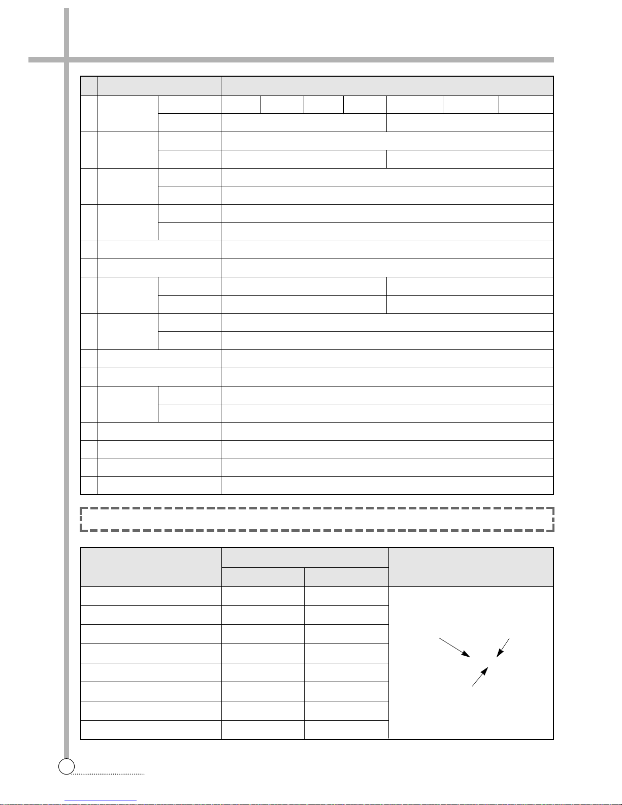
NO. ITEM SPECIFICATIONS
1 POWER VOLTAGE
SOURCE FREQUENCY 60Hz 50Hz
2 POWER 800C 480W NON PUMP/515W PUMP
CONSUMPTION
900C 630W 560W
3 DIMENSION 800C Net with legs: 830X475X950, Packed without legs : 870X533X947 (WXDXH,mm)
900C Net with legs: 830X475X970, Packed without legs : 870X533X947 (WXDXH,mm)
4 MACHINE 800C Non pump (Net:24kg Packed up:27kg), Pump (Net:25kg Packed up:28kg)
WEIGHT 900C Non pump (Net:25kg Packed up:28kg), Pump (Net:26kg Packed up:29kg)
5 WASHING COURSE STRONG, NORMAL
6 WATER LEVEL 900C-EXTRA HIGH:70l, HIGH:60l, MEDIUM:52l, LOW:44l
7 REVOLUTION WASH 800C-170 rpm / 900C-190 rpm 800C-170 rpm / 900C-190 rpm
PER MINUTE SPIN 1700 rpm 1400 rpm
8 TIMER WASH MAX. 15 min., Manual operation
SPIN MAX. 5 min., Manual operation
9 WASHER TYPE PULSATOR TYPE
10 SPIN TYPE CENTRIFUGALLY SEPARATED TYPE
11
MAXIMUM MASS
WASH 800C-6.0 kg / 900C-7.0 kg
OF TEXTILE SPIN 5.5 kg
12 WATER SUPPLY MANUAL
13 SPIN RINSE O
14 OUTLET OF DRAIN HOSE REAR
15 LINT FILTER O
POWER SOURCE
SUFFIX
EXPLANATION
NON PUMP PUMP
AC 100V 50/60Hz J -
AC 110V 60Hz T TP
AC120V 60Hz A AP
AC 220V 50Hz N NP
AC 220V 60Hz L LP
AC 240V 50Hz M MP
AC 110/220V 50Hz D DP
AC 120/240V 60Hz S SP
1. SPECIFICATIONS
2
SPECIFICATIONS
NOTE : Explanation table for suffix of names.
AC 110/220V AC 220V AC 240VAC 110V AC 120V AC 220V
AC 127/220V
Model Name Pump
DWM-XXXX N or NP
Power Source

2. EXTERNAL VIEW
3
STRUCTURE
Structure Of The Wash Machine
Control Panel (Panel b Ass y)
11
INLET WATER
Connect inlet hose to supply water in the WASH
TUB or BASKET SPIN.
22
LEVER WATER SUPPLY SELECTOR
Left : water supply in the WASH TUB.
Right : water supply in the BASKET SPIN.
33
WASH TIMER
Use to select the desired time for washing or rinsing.
44
WASH ACTION
Use to select wash action. (STRONG”, “NORMAL”)
55
V ALVE SELECTOR
Select “WASH.RINSE” for washing and rinsing, and
“DRAIN” to drain the water.
(In case PUMP MODEL turn on the drain pump)
“OFF” to turn off the drain pump. (Only PUMP
MODEL)
66
SPIN TIMER
Used to select the desired time for spinning.
Wash Spin
Wash Timer
15
12
9
6
3
0
Wash Action
Strong
Normal
Spin Timer
5
4
3
2
1
0
Off
Wash-Rinse
Valve Selector
Drain
WA TER DRAIN HOSE
(PUMP MODEL)
PULSATOR
BASE UNDER
OVERFLOW FILTER
SPIN DRYER LID
When you open this lid while the spin basket is spinning,
the spinning will be stopped by brake system.
LINT FILTER
This is used for gathering the
dregs which are made during
washing.
WASH TUB LID
During operation, close the
wash tub lid.
POWER CORD
The plug’s shape may not correspond with this drawing.
“WARNING-THIS APPLIANCE
MUST BE EARTHED”
SAFETY COVER
INNER LID
SPIN DRYER BASKET.
WA TER DRAIN HOSE
(NON-PUMP MODEL)
GUIDE
CASCADE
1
3
2
456
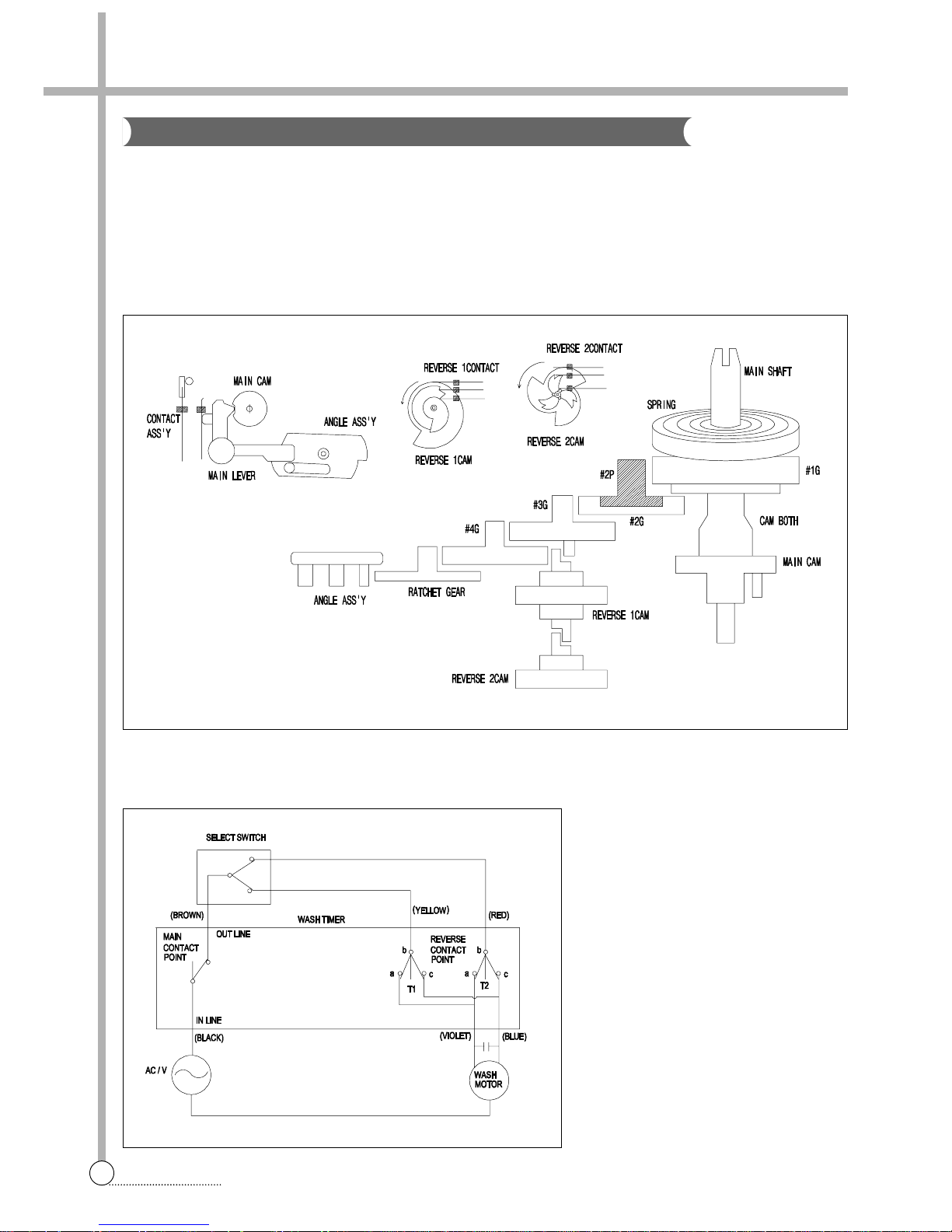
FUNCTION
The main switch remains ON during the washing time set by turning the timer knob.
At the same time, the internal switch T1 and T2 which provide power to WASH MOTOR alternately at assigned Intervals.
Select switch knob sets the wash type by means of controlling the interval of internal switch contact.
STRUCTURE AND PRINCIPLE OF ACTIVATION
3. PRINCIPLES OF OPERATION AND EXPLANATION OF FUNCTIONS
4
WASH TIMER
Wash Timer
CIRCUIT DIAGRAM

5
SPIN TIMER
FUNCTION
The spin timer is the switch providing power to the SPIN MOTOR(DRAIN PUMP MOTOR) during the set spin dry
time, and is a spring-type time switch comes on upon turning and those contact points comes off after the set time.
STRUCTURE AND PRINCIPLE OF ACTIVATION
1) The main shaft turns due to the unwinding force when the spin timer is turned, the spring wound with that force
being delivered through each gear and the spring slowly unwinding at a speed finally controlled by the angle
assembly .
2) The contact point Turns ON and the assembly angle is set in motion which is in the CAM groove in the OFF
state, comes off the groove when the main shaft is turned to wind the spring. The contact point turns OFF,
return to CAM groove when the spring unwind completely .
SAFETY DEVICE FOR BASKET SPIN
The BASKET SPIN is an apparatus which eliminates the water from the laundry through centrifugal separation
generated by rapid revolution(approximately 1,600rpm for 60Hz). Accordingly , there are a DOOR SWITCH to cut
off the power going into the DOOR SPIN is opened and a brake system to stop the rotating BASKET SPIN.
DOOR SWITCH
When the DOOR SPIN is opened during spinning, the DOOR
SWITCH LEVER which sites atop the DOOR SPIN falls off the
contact, and cuts off the power going into the SPIN MOTOR.
Spin Timer
6
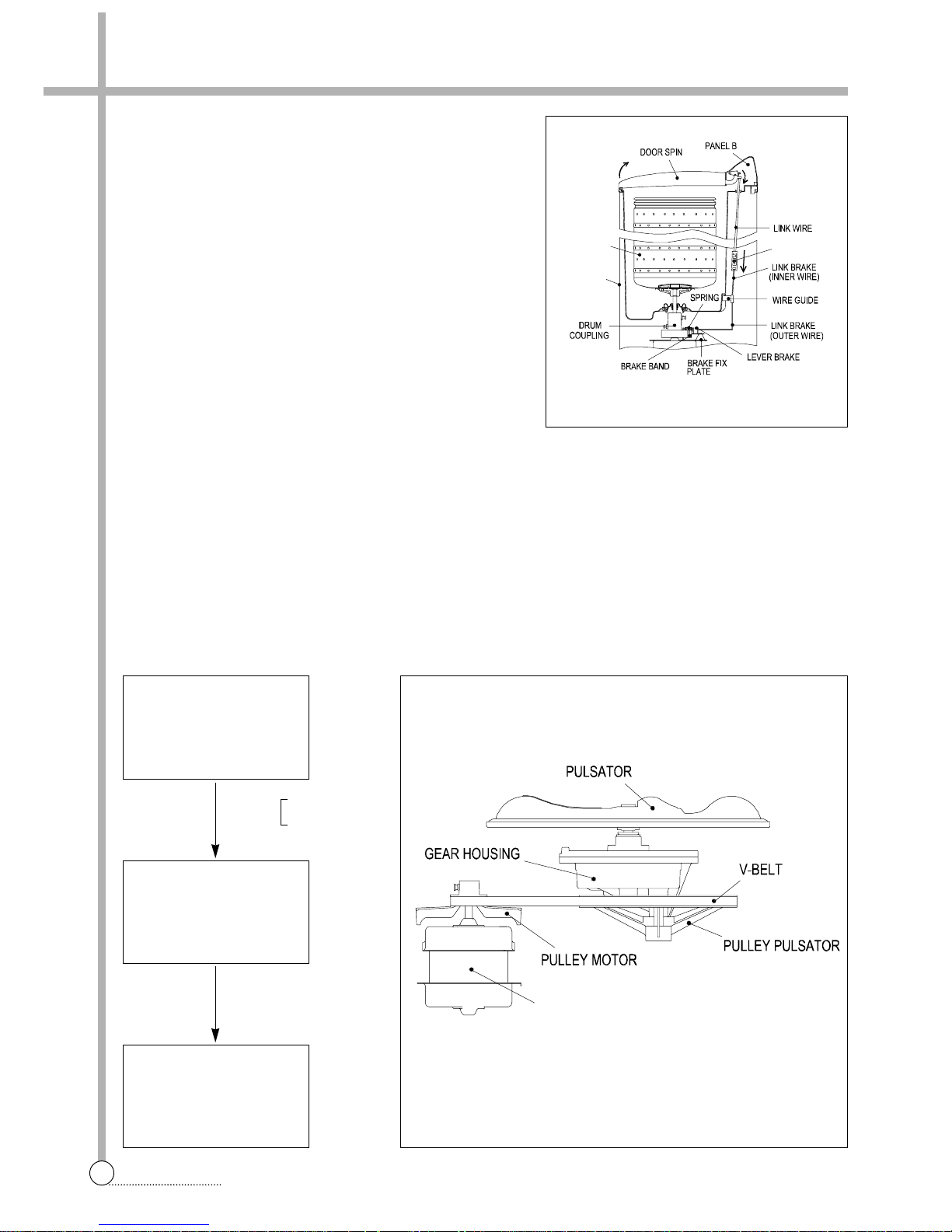
BRAKE SYSTEM
BRAKE SYSTEM
When the DOOR SPIN is opened, LINK WIRE which connect
to DOOR SPIN loosens. And then the BRAKE BAND touches
the DRUM COUPLING assemply and stops the SPIN DRYER
as it is pulled by the SPRING in the BRAKE FIX PLA TE
assembly .
BRAKE BAND GAP CONTROL METHOD
The BAND BRAKE works best when the gap between it and
the DRUM COUPLING is about 2mm when the DOOR SPIN
is closed. The SPIN DRYER stops slowly if the gap between
the two is too narrow, the SPIN DR YER revolution is affected
and the PLA TE CONTROL WIRE may be adjusted to maintain the BRAKE BAND gap adequately .
WASH DECELERATOR ASSEMBLY
The initial deceleration following the activation of the WASH MOTOR takes place through the PULLEY MOTOR
and PULLEY PULSA TOR, and the secondary deceleration is done by the gear in the GEAR HOUSING which also
increeases their revolution strength. This revolution speed and strength is delivered to the PULSATOR, which is
then able to cause water current that is strong yet soft so that wash loads are not damaged.
PLATE
CO NTROL W IRE
BA
BASE
SKET SPI N
WASH M OTOR
MOTOR WASH
About 1,700rpm(60Hz)
1,400rpm(50Hz)
M-Pully
2.5:1 (50Hz)
3.0:1 (60Hz)
PULLEY PULSATOR
About 560rpm(50/60Hz)
PULSATOR
About 170rpm(50/60Hz)
G/H (3.3:1)
7
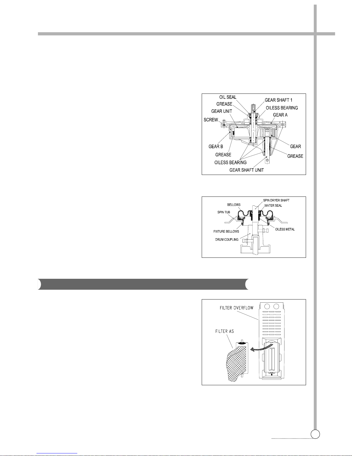
GEAR HOUSING
GEAR HOUSING ASS’Y
The GRAR HOUSING ASSEMBL Y is a transmission device which turns the PULSATOR at 3.3:1 lowered speed
through the gear unit assembly which receives power at the GEAR SHAFT UNIT.
1) The two sides of the GEAR SHAFT UNIT are supported by the
OILLESS BEARING in the GEAR HOUSING ASSEMBL Y.
2) The GEAR UNIT ASSEMBLY is connected to the GEAR
SHAFT 1 and GEAR SHAFT UNIT by the GEAR and GEAR
UNIT respectively .
3) The two sides of GEAR SHAFT 1 are supported by the OIL
SEAL and OILLESS BEARING in the GEAR HOUSING
ASSEMBL Y.
SPIN GELLOWS ASS’Y
The wrinkled rubber device on the botton of the BASKET SPIN is
called SPIN BELLOWS ASSEMBL Y.
It has a waterseal and a oilless metal inside to prevent leakage
and so that the BASKET SPIN may work smoothly .
Much lint may be obtained depending upon the kind of clothes to
be washed and same of the lint may also be suck to the clothes.
To minimize this possibility, a lint filter is provied on the upper part
of the FIL TER OVERFLOW to filter the wash water.
Use of the lint filter during every wash is recommend.
CLEANING THE LINT FILTER
1) Remove the FIL TER AS from the FILTER OVERFLOW by pressing it downwards.
2) Turn the FILTER AS inside out, and wash the lint off with water.
3) Return the FIL TER AS it was, and fix the FILTER AS to the FIL TER OVERFLOW.
STRUCTURE
Filter
 Loading...