

Page 1

Service Manual
Washing Machine
Model: DWM-750MA
DAEWOO ELECTRONICS CORP.
S/M No. : DM750MA001
http : //svc.dwe.co.kr Jan. 2003
✔
Caution
: In this Manual, some parts can be changed for improving, their
performance without notice in the parts list. So, if you need the
latest parts information,please refer to PPL(Parts Price List) in
Service Information Center (http://svc.dwe.co.kr).
Page 2

AUTO WASHER AUTO WASHER AUTO WASHER AUTO WASHER AUTO WASHER AUTO WASHER AUTO WASHER AUTO WASHER AUTO WASHER AUTO
WASHER AUTO WASHER AUTO WASHER AUTO WASHER AUTO WASHER AUTO WASHER AUTO WASHER AUTO WASHER AUTO WASHER AUTO WASHER
AUTO WASHER AUTO WASHER AUTO WASHER AUTO WASHER AUTO WASHER AUTO WASHER AUTO WASHER AUTO WASHER AUTO WASHER AUTO
WASHER AUTO WASHER AUTO WASHER AUTO WASHER AUTO WASHER AUTO WASHER AUTO WASHER AUTO WASHER AUTO WASHER AUTO WASHER
AUTO WASHER AUTO WASHER AUTO WASHER AUTO WASHER AUTO WASHER AUTO WASHER AUTO WASHER AUTO WASHER AUTO WASHER AUTO
WASHER AUTO WASHER AUTO WASHER AUTO WASHER AUTO WASHER AUTO WASHER AUTO WASHER AUTO WASHER AUTO WASHER AUTO WASHER
AUTO WASHER AUTO WASHER AUTO WASHER AUTO WASHER AUTO WASHER AUTO WASHER AUTO WASHER AUTO WASHER AUTO WASHER AUTO
WASHER AUTO WASHER AUTO WASHER AUTO WASHER AUTO WASHER AUTO WASHER AUTO WASHER AUTO WASHER AUTO WASHER AUTO WASHER
WASHING MACHINE
CCoonntteennttss
1. SPECIFICATIONS ..................................................................................................... 1
2. EXTERNAL VIEW ..................................................................................................... 2
3. PRINCIPLES OF OPERATION AND EXPLANATION OF FUNCTIONS................ 3
4. DIRECTION FOR DISASSEMBLY AND ASSEMBLY ..............................................7
5. TROUBLESHOOTING GUIDE ................................................................................10
6. EXPLODED VIEW AND PARTS LIST.....................................................................15
7. WIRING DIAGRAM ..................................................................................................23
Page 3
NO. ITEM SPECIFICATIONS
1 POWER VOLTAGE AC 127V
SOURCE FREQUENCY 60Hz
2 POWER WASH 330W
CONSUMPTION
SPIN 180W
3 DIMENSION NET : 813X500X930, PACKED UP : 830X530X970 (WXDXH)
4 MACHINE WEIGHT NET : 29kg, PACKED UP : 32kg
5 WASHING COURSE STRONG, NORMAL
6 WATER LEVEL HIGH:62l, MEDIUM:54l, LOW:47l
7 REVOLUTION WASH 100 rpm
PER MINUTE SPIN 1700 rpm
8 TIMER WASH MAX. 15 min., Manual operation
SPIN MAX. 5 min., Manual operation
9 WASHER TYPE AGITATOR TYPE
10 SPIN TYPE CENTRIFUGALLY SEPARATED TYPE
11
MAXIMUM MASS
WASH 7.0 kg
OF TEXTILE SPIN 5.5 kg
12 WATER SUPPLY MANUAL
13 SPIN RINSE O
14 OUTLET OF DRAIN HOSE REAR
1. SPECIFICATIONS
2
SPECIFICATIONS
Page 4
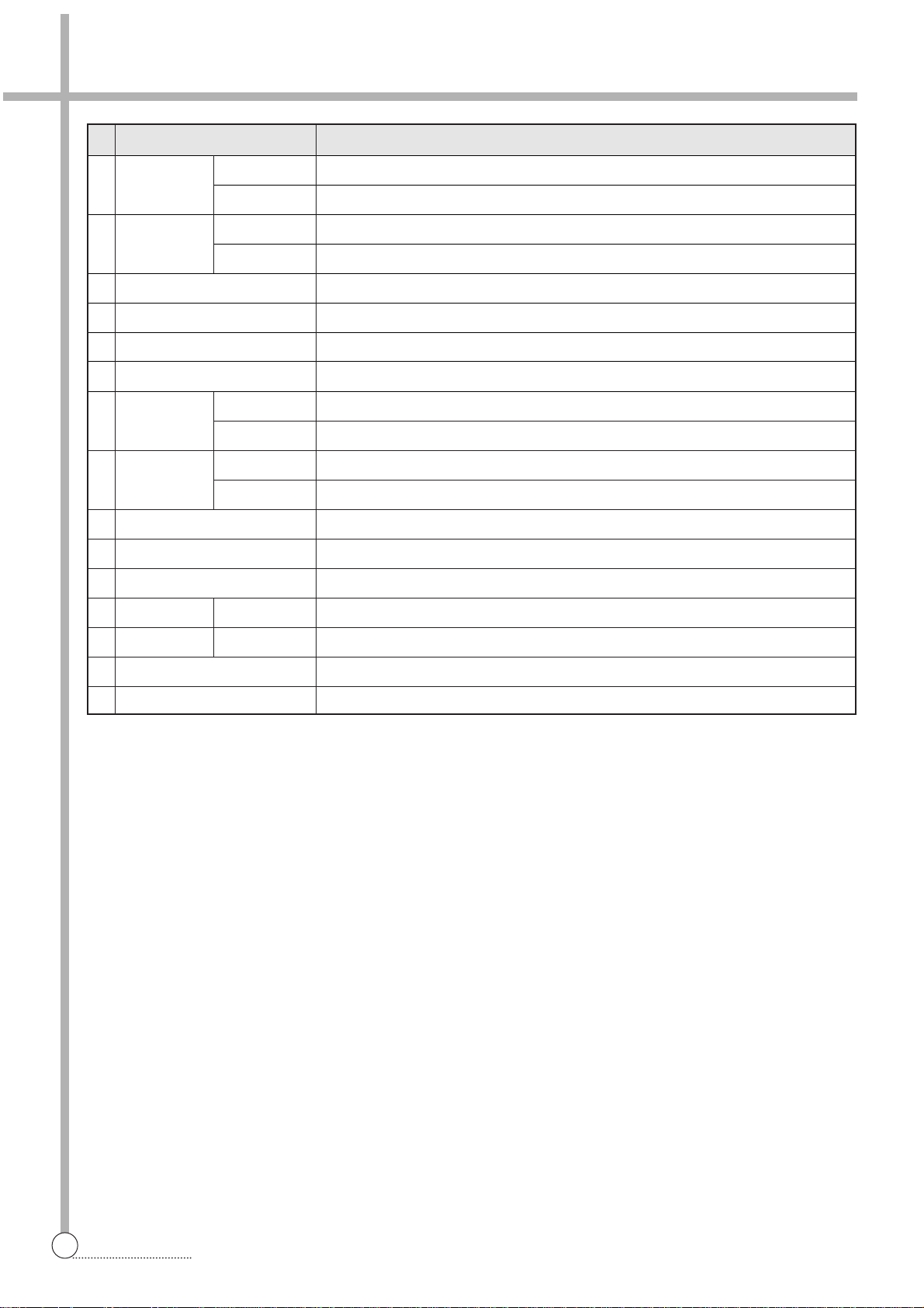
2. EXTERNAL VIEW
3
STRUCTURE
Structure Of The Wash Machine
F unctions of Control Panel
11
WATER INLET - WASH
Connect inlet hose to supply water in the wash tub.
22
WASH TIMER
Use to select the desired time for washing or rinsing.
33
WASH ACTION
Use to select wash action. (“STRONG”, “NORMAL”)
44
LEVER SELECTOR
Select “WASH.RINSE” for washing or rinsing, and
“DRAIN” to drain the water. (In case pump model,
turn on the DRAIN PUMP.) “OFF to turn off the
DRAIN PUMP. (Only pump model)
55
SPIN TIMER
Used to select the desired time for spinning.
66
WATER INLET - SPIN
Connect inlet hose to supply water in the spin tub.
DRAIN STRAINER
COVER SAFETY
DOOR SPIN
BASKET SPIN
PLATE T
DRAIN HOSE
CABINET
TUB
PUL SATOR
DOOR WASH
PANEL B
GUIDE FILTER
WATER INLET
WASH TUB
WASH TIMER WASH ACTION
0
15
12
3
6
9
VALVE
SELECTOR
NORMAL WASH/RINSE
STRONG
OFF
SPIN TIMER WATER INLET
0
5
DRAIN
4
1
2
3
SPIN TUB
Page 5
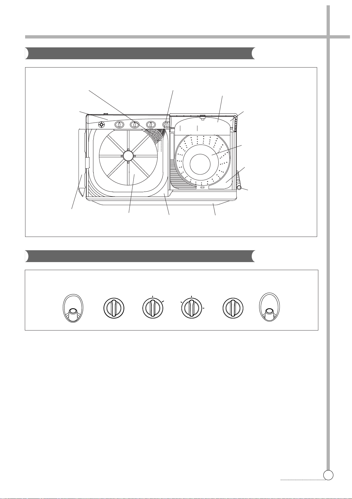
FUNCTION
The main switch remains ON during the washing time set by turning the timer knob.
At the same time, the internal switch T1 and T2 which provide power to WASH MOTOR alternately at assigned Intervals.
Select switch knob sets the wash type by means of controlling the interval of internal switch contact.
STRUCTURE AND PRINCIPLE OF ACTIVATION
3. PRINCIPLES OF OPERATION AND EXPLANATION OF FUNCTIONS
4
CONTROL PANEL
W ash Timer
CIRCUIT DIAGRAM
Page 6
5
PROCEDURE
FUNCTION
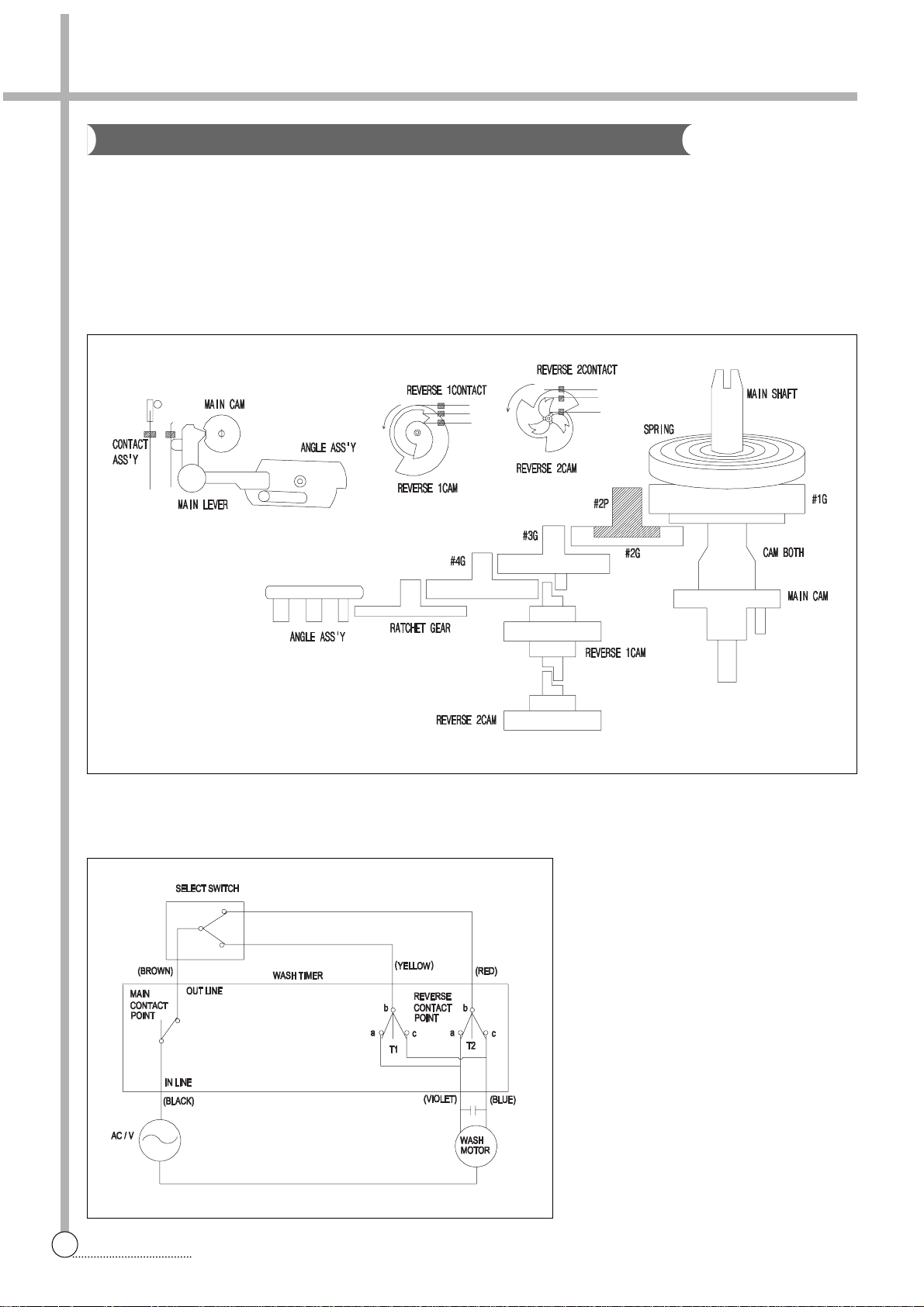
The spin timer is the switch providing power to the SPIN MOTOR(DRAIN PUMP MOTOR) during the set spin dry
time, and is a spring-type time switch comes on upon turning and those contact points comes off after the set time.
STRUCTURE AND PRINCIPLE OF ACTIVATION
1) The main shaft turns due to the unwinding force when the spin timer is turned, the spring wound with that force
being delivered through each gear and the spring slowly unwinding at a speed finally controlled by the angle
assembly.
2) The contact point Turns ON and the assembly angle is set in motion which is in the CAM groove in the OFF
state, comes off the groove when the main shaft is turned to wind the spring. The contact point turns OFF,
return to CAM groove when the spring unwind completely.
SAFETY DEVICE FOR BASKET SPIN
The BASKET SPIN is an apparatus which eliminates the water from the laundry through centrifugal separation
generated by rapid revolution(approximately 1,600rpm for 60Hz). Accordingly, there are a DOOR SWITCH to cut
off the power going into the DOOR SPIN is opened and a brake system to stop the rotating BASKET SPIN.
DOOR SWITCH (Option)
When the DOOR SPIN is opened during spinning, the DOOR
SWITCH LEVER which sites atop the DOOR SPIN falls off the
contact, and cuts off the power going into the SPIN MOTOR.
Spin Timer
Page 7
6
PROCEDURE
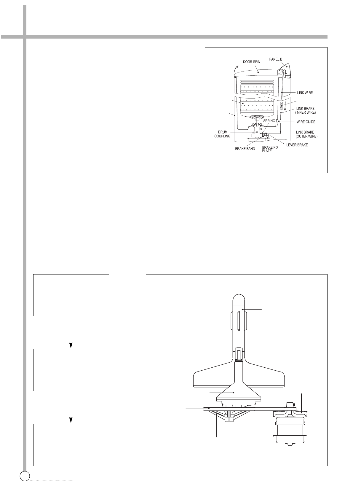
BRAKE SYSTEM (Option)
When the DOOR SPIN is opened, LINK WIRE which connect
to DOOR SPIN loosens. And then the BRAKE BAND touches
the DRUM COUPLING assemply and stops the SPIN DRYER
as it is pulled by the SPRING in the BRAKE FIX PLATE
assembly.
BRAKE BAND GAP CONTROL METHOD
(Option)
The BAND BRAKE works best when the gap between it and
the DRUM COUPLING is about 2mm when the DOOR SPIN
is closed. The SPIN DRYER stops slowly if the gap between
the two is too narrow, the SPIN DRYER revolution is affected
and the PLATE CONTROL WIRE may be adjusted to main-
tain the BRAKE BAND gap adequately.
WASH DECELERATOR ASSEMBLY
The initial deceleration following the activation of the WASH MOTOR takes place through the PULLEY MOTOR
and PULLEY PULSATOR, and the secondary deceleration is done by the gear in the GEAR HOUSING which also
increeases their revolution strength. This revolution speed and strength is delivered to the PULSATOR, which is
then able to cause water current that is strong yet soft so that wash loads are not damaged.
PLATE
CO NTROL W IRE
BA
BASE
SKET SPI N
MOTOR WASH
About 1,700rpm
M-Pully (4:1)
PULLEY PULSATOR
About 425rpm
AGITATOR
About 100rpm
G/H (4.18:1)
GEAR HOUSING
V-BELT
PULLEY AGITATOR
AGITATOR ASS’Y
PULLEY
MOTOR
Page 8

7
PROCEDURE
GEAR HOUSING ASS’Y
The GRAR HOUSING ASSEMBLY is a transmission device which turns the Agitator at 4.18:1 lowered speed
through the gear unit assembly which receives power at the GEAR SHAFT UNIT.
1) The two sides of the GEAR SHAFT UNIT are supported by the
OILLESS BEARING in the GEAR HOUSING ASSEMBLY.
2) The GEAR UNIT ASSEMBLY is connected to the GEAR
SHAFT 1 and GEAR SHAFT UNIT by the GEAR and GEAR
UNIT respectively.
3) The two sides of GEAR SHAFT 1 are supported by the OIL
SEAL and OILLESS BEARING in the GEAR HOUSING
ASSEMBLY.
SPIN BELLOWS ASS’Y
The wrinkled rubber device on the botton of the BASKET SPIN is
called SPIN BELLOWS ASSEMBLY.
It has a waterseal and a oilless metal inside to prevent leakage
and so that the BASKET SPIN may work smoothly.
CLEANING THE OVERFLOW FILTER
1) Pull the overflow filter out from the wash tub by tugging.
2) Wash off, remove lint from the filter and also clean around the
overflow hose.
3) Reassemble by matching the two protrusions at the bottom of
the filter to the slits in the wash tub and then fix the filter into
position.
CLEANING THE DRAIN FILTER
1) To remove the agitator, remove the lint filter assembly.
2) Remove the screw from agitat and pull the agitator upward.
3) Using screw driver undo the securing screws.
4) Rinse the water and reinstal the lint filter.
SHAFT AGITATOR
OILLESS METAL
OILLESS METAL
GEAR
INNER GEAR
OILLESS METAL
SHAFT PULLEY
STRUCTURE
F ilt e r
WATER SEAL
OILLESS METAL
SPIN DRYER
SPIN DRYER SHAFT
BELLOWS
SPIN TUB
BELLOWS PACKING
CRUM COUPLING
Page 9

8
4. DIRECTION FOR DISASSEMBOY AND ASSEMBLY
DIRECTIONS
1. Remove 5 screws on the panel 2. Remove 7 screws on the cover B.
R eplacing Wash Timer And Spin Timer
3. Remove connector and link valve. 4. Remove knob and 2 screws on the bracket panel.
5. Remove control lever and timer.
Page 10

9
CONNECTION
1. Remove 2 screws on the cover B. 2. Separae harness as connectors.
R eplacing Motor For Spin And Was h
3. Remove bolt and nut on the upper side of the drum
coupling as and lift up the basket spin.
4. Remove 1 screw fixing cabinet.
7. Remove 3 screws on the base and Remove wash
motor.
8. Remove 3 screws and spin motor.
5. Remove bolt connecting motor pulley and pulsator
pulley.
6. Remove panel front and 3 screws on flange of the
tub. And lift up the tub assembly.
Page 11

5. TROUBLESHOOTING GUIDE
10
CONVENIENCE
PROBLEM
Agitator
does not
rotate.
CHECK POINT CAUSE SOLUTION
Pull out the power plug to repair and make sure that the Washing Machine has been properly
grounded.
NOTES
Concerning Wash
Is the Power properly connected?
Is the Fuse blown?
Reconnect the Power Cord.
Change the Fuse.
Is there a whirring sound from the
Wash Motor when turned on?
Is the of Condeser properly
connected?
Motor does not start due to
opening the Condenser circuit
Is the Motor hot?
(In case there is Thermal Protector)
Is the Wiring good?
(Refer to the Wiring Diagram)
Is the connact of Wash Timer good? Defective Wash Timer
Defective Wash Motor
Power has been cut off by
the Thermal Protector.
Improper wiring
Reconnect the Condenser.
Replace Wash Timer
Replace Wash Motor
Reload with proper wash
load.
Power restored when
Motor cools
Reconnect the wiring
Agitator
does not
rotate
smoothly.
Is the Wash Load appropriate?
Are the Agitator and Motor Pulleys
securely assembled?
Does the V-Belt slip?
Are there impurities between the
Agitator and Tub.
Revolution obstructed by
impurities
Remove impurities after
disassembling Agitator
Defect of mechanical
assembly
Worn out V-Belt
Tighten the screws fixed on
the Pulleys.
Replace V-Belt
YES
NO
NO
YES
YES
NO
YES
NO
NO
NO
NO
YES
YES
NO
NO
YES
YES
YES
YES
YES
NO
Page 12

11
EXPLANATION
PROBLEM
Agitator
does not
rotate
smoothly.
CHECK POINT CAUSE SOLUTION
PROBLEM CHECK POINT CAUSE SOLUTION
Concerning Spin
Does the Gear Housing Shaft
rotate proply when the Agitator
has been disassembled?
Worn out the Serration
within the Agitator.
Defective Gear Housing Replace Gear Housing.
Replace Agitator
Keep the Door Spin *O
closed during spin.
The contact Door Switch is
open.
The Spin
Dryer does
not spin.
Is the Door Spin *O open?
Is the Fuse blown?
Is there a whirring sound from the
Spin Motor when turned ON?
Change the Fuse.
NO
YES
Agitator only
rotates in one
direction.
Is the wiring of Wash condenser
properly connected?
Is the wiring of Wash Timer properly connected?
Impropely Wiring
Defective Wash timer Replace Wash Timer.
Reconnect the Wash Timer.
Improper Connection Reconnect
YES
YES
NO
NO
NO
There is
excessive
noise during
Washing
Are there strange noise frome Tub
when the Agitator rotate?
Agitator improperly
assembled.
Something is in contact with
the Agitator Pulley or Motor
Pulley or other rotating parts.
Adjust the parts so that
there are no impurities in
contact with rotating parts
Tighten the Agitator fixing
screw.
Impurites between Agitator
and tub
Remove impurities after disassembling Agitator.
YES
NO
YES
YES
NO
NO
NO YES
Page 13

12
THE REPAIR
PROBLEM
The Spin
Dryer does
not spin.
There are
strange noise
and servere
vibration during
spinning.
CHECK POINT CAUSE SOLUTION
Is the Condenser properly
connected?
Motor does not start due to
opening the Condenser circuit.
Reconnect.
The Brake Band is touching
the Drum Coupling Assembly.
NO
YES
NO
NO
NO
YES
YES
YES
YES
YES
YES
NO
YES
Brake wire is too long.
Assemble after loosening
Wire Guide Screw and
adjusting downward.
BRAKE SPRING is broken. Replace Brake Spring.
Power has been cut off by
the Thermal Protector
Is the Motor hot? (In case there is
Thermal Protector)
Is the wiring good? (Refer to
Wiring Diagram)
Improper wiring Reconnect wiring
Is the Door Switch Lever properly
placed on the Door Spin *O?
Defective connection
Replace Door Switch or
reshape the Lever.
Is the Door Switch terminal properly connected?
Improper wiring Reconnect the terminal.
Is the Contact of Spin Timer good?
Defective Spin Timer Replace the Spin Timer.
Defective Spin Motor
Spin Dryer does not balanced
due to wash load.
Tub is in contact with the
object sticking out.
Reload the clothes and
press down the Safety
Cover into Spin Basket.
Tighten the Bolt Drum
Coumling Assembly.
Is the assembly between the
Drum Coupling Assembly and
Spin Motor or Spin Dryer loose?
Improper structural assembly
Is the Spin Dryer itself well balanced?
Spin Dryer unbalance Re-assemble Spin Dryer.
Are clothes or the Safety Cover
stick out from Spin Basket?
Reload the clothes so they
are well balanced
Is the wash load well balanced?
Replace the Spin Motor.
Power restored when motor
cools.
YES
YES
NO
NO
YES
NO
NO
NO
YES
NO
Page 14

13
TROUBLE SHOOTING
PROBLEM CHECK POINT CAUSE SOLUTION
The Waterseal or the oilless metal in the Bellows
Assembly worn out.
Replace Bellows Assembly.
There is leakage during
spin drying.
Is the Bellow Assembly properly
assembled?
The Waterseal or the
Oiless Metal in the Bellows
Assembly is worn out.
Replace Bellows
Assembly.
Waterproofing not working
due to defective assembly.
Re-assemble
Bellows Assembly.
YES
NO
YES
YES
Spin Dryer
does not
stop with the
Door Spin
*O open
The Brake Band touches the
Drum Coupling when the Door
Spin *O open.
Brake Band is worn out.
Defective
Door Switch
Is the electric connection of the
Door Switch good?
Replace
Door Switch
The contact of the Door
Switch does not open due
to deformity of the lever of
Door Switch.
Replace Door Switch or
reshape the lever of Door
Switch.
Replace Brake Band or
Brake Fix Assembly.
Brake wire is too short.
Replace after loosening
Wire Guide and adjusting
upward.
NO
NO
Concerning Drainga (Pump)
PROBLEM
Drainage is
not satisfactory
CHECK POINT CAUSE SOLUTIONPROBLEM CHECK POINT CAUSE SOLUTION
Is the height of the drainage area where
the Drain Hose hangs over 1m?
The Drain Hose is too high.
Hang the Drain Hose lower.
Are there impurities in the Drain
Strainer?
YES
NO
NO
Impurities are obstructing
drainage.
Disassemble Agitaor and
take out impurities in drain
Strainer
Impurities are obstructing
drainage.
Are there impurities in the Valve
Housing or Inlet Joint?
Remove impurities or
replace Valve Housing or
Inlet Joint.
Impurities are blocking the
Drain Hose
Remove impurities
YES
YES
NO
Page 15

14
TROUBLE SHOOTING
PROBLEM CHECK POINT CAUSE SOLUTION
Draining
does not
function during drain
selecting
Is the Wash Timer OFF when the Drain
Selector is in the DRAIN position
Pump Motor does not work
because Power is open.
Adjust Wash Timer for adequate draining time.
Is the pump Motor wiring properly
connected?
Defective Pump motor Replace Pump Motor
YES
NO
YES
Defective wiring Reconnect wiring
NO
Drain does
not function
during Spin
drying
Are the wiring of the Spin Timer
and the Pump Motor good?
Defective wiring Reconnect wiring
Is the Spin Timer’s contact good?
Defective Pump motor Replace Pump Motor
NO
YES
Defective Spin Timer Replace Spin Timer
NO
Concerning Drainage (Non Pump)
PROBLEM CHECK POINT CAUSE SOLUTION
NO
NO
Drainage is
not satisfactory.
Are there impurities in the Drain
Strainer?
Impurities are obstructing
drainage.
Are there impurities in the Valve
Housing or Inlet Joint?
Remove impurities or replace
Valve Housing or Inlet Joint
Impurities are blocking the
Drain Hose
Remove impurities
Impurities are obstructing
drainage.
Disassemble Agitator and take
out impurities in Drain Strainer
YES
YES
YES
Water keeps
draining during wash
Is the Drain Selector on the operation Panel at the DRAIN position?
There are impurities
between the impurities
Housing and Valve Bellows.
Remove impurities Or replace
Valve Housing.
Mismanupilation
Turn Drain Selector to
WASH/RINSE position
NO
Page 16

6. EXPLODE VIEW AND PARTS LIST
15
TROUBLE SHOOTING
Assy Panel Back
Page 17

16
TROUBLE SHOOTING
assy panel
NO. PART NAME PART CORD SPECIFICATION Q’TY REMARKS
P01 KNOB 3613403800 160C, ABS 4.0000 160C
P02 PANEL B 3614240000 HIPS 1.0000
P03 TIMER WASH 3619911170 S-DT15NT-M 1.0000
P04 LEVER CONTROL 3613701400 POM 2.0000 500M
P05 LINK VALVE 3617804600 PP BAND 0.7T, L2=796 1.0000 YELLOW
P06 TIMER SPIN 3619900900
AC 125V/6A,250V/3A S-6200A
1.0000
P07 BRACKET CONTROL 3610607300 HIPS 1.0000
P08 SWITCH DRAIN 3619043700 VP531A-2H, 250VAC/15A 1.0000
P09 SPRAY HOSE 3613225400 PE-LD 1.0000
assy accessory
NO. PART NAME PART CORD SPECIFICATION Q’TY REMARKS
A01 SAFETY COVER 3611418900 PE-LD+EVA 1.0000
✔ Caution:
In this Service Manual, some parts can be changed for improving, their performance without notice in the parts list. So, if you need the
latest parts information, please refer to PPL(Parts Price List) in Service information Center(http://svc.dwe.co.kr)
Page 18

17
TROUBLE SHOOTING
Assy Tu b
Page 19

18
PCB ASS’Y
assy tub
NO. PART NAME PART CORD SPECIFICATION Q’TY REMARKS
T01 TUB 4507K05013 PP 1.0000
T02 DOOR WASH 36117A0700 HIPS 1.0000
COLOR OPTION
T03 PANEL F 3614240100 HIPS 1.0000
COLOR OPTION
T04 PULSATOR ASS'Y 4507K32001 1.0000
COLOR OPTION
T05 SPECIAL SCREW 450M702011 SUS 430 1.0000
T06 CAP AGITATOR 3610915400 PP 1.0000
T07 BASE WATER SUPPLY 3610312300 PP 1.0000
T08 STRAINER DRAIN *D 4507K01020 PP 1.0000
T09 STRAINER DRAIN *U 4507K01030 PP 1.0000
T10 PIPE WATER LEVEL 3614404500 PE L=193MM 1.0000 PUMP MODEL
T11 FILTER 4507K01042 PP 1.0000
T12 RING BASKET 3614602300 PP 1.0000
T13 BASKET SPIN 3619103300 PP 1.0000
T14 BASKET SPIN AS 3619103510 DWM-5510AE-MEC 1.0000
T15 PLATE TOP 3614529600 PP 1.0000
T16 COVER *I 4507K33021 PP 1.0000
T17 DOOR SPIN 36117A0600 HIPS 1.0000
COLOR OPTION
T18 COVER SPRING 4508D01061 SWC D1.75 1.0000
T19 RING O 4506H05050 N.B.R 1.0000
T20 BOX GEAR AS 4508D17001 RW-622 1.0000
T21 P-PULLEY AS 4506H21000 - 1.0000
T22 SPECIAL BOLT 3616006400 SM18C + SILOCK(M6) 1.0000
T23 BELLOWS AS 3616400900 3.6KG 1.0000
T24 FIXTURE 3612004400 PP 1.0000
T25 CASE VALVE 4506B06015 PE-HD 1.0000
T26 BELLOWS VALVE 4505C06040 NR 1.0000
T27 ROD VALVE 3618504000 PP 1.0000
T28 SPRING VALVE 4505C0602M SUS 304 WR D1.0 1.0000
T29 VALVE CAP 4505F06013 PE-HD 1.0000
T30 HOSE OVERFLOW 4506H06010 PE-HD 1.0000
T31 INLET JOINT 4506B06033 PP 1.0000
T32 DRAIN HOSE AS 36196005C2 - 1.0000
T33 HARNESS EARTH GEAR 3612715700 G/H EARTH 1.0000
✔ Caution:
In this Service Manual, some parts can be changed for improving, their performance without notice in the parts list. So, if you need the
latest parts information, please refer to PPL(Parts Price List) in Service information Center(http://svc.dwe.co.kr)
Page 20

19
WIRING DIAGRAM
Assy Main
Page 21

20
WIRING DIAGRAM
assy main
assy tub
NO. PART NAME PART CORD SPECIFICATION Q’TY REMARKS
M01 CABINET 3610804600 PCM (SGCC T0.6) 1.0000
COLOR OPTION
M02 PLATE UPPER 3614507400 PP 1.0000
COLOR OPTION
M03 CORD POWER WAK42H762- A VCTFK 2X0.75 2.3M GY 1.0000
M04 BELT V 4507K01010 M-31 1.0000
M05 PULLEY MOTOR 3618401480 PRESS, DS=10,DP48.5 1.0000
M06 NUT HEX 7392800011 M8*P1.5, MFZN 1.0000
M07 WASH SPRING 7401008011 SW-8 MFZN 1.0000
M08 SPECIAL BOLT 3616003100 M5*35 WASHER 3.0000
WITH WASHER (M09)
M09 MOTOR CONDENSER 3964820300 AC120V/60HZ,UL,TP,W18SD 1.0000
M10 CUSHION MOTOR 450M712020 NR 3.0000
M11 CUSHION SPOT 450M712010 PP 1.0000
M12 UNIT CAPACITOR 3618943210 41.6/16UF,200/250VAC 1.0000
M13 BASE U 4507K34012 PP 1.0000
M14 DRUM COUPLING AS 4507K16001 RW-481,622,623 1.0000
M15 NUT HEX 7393600011 6N-3-6 MFZN 1.0000
M16 BOLT HEX (P) 7342602011 6B-2 6X20 POINTING MFZN 1.0000
M17 NUT HEX 7393600011 6N-3-6 MFZN 1.0000
M18 BOLT HEX (P) 7342602011 6B-2 6X20 POINTING MFZN 1.0000
M19 SCREW TAPPING 7122502011 T2S TRS 5X20 MFZN 3.0000
M20 MOTOR CONDENSER 3964820400 AC120V/60HZ,UL,TP,S50 1.0000
M21 STOPPER 4506H14020 PE-HD 3.0000
M22 SPRING CUSHION 4507K14010 SEC D3.2 3.0000
M23 RUBBER DAMPING 4506H14030 NBR 3.0000
M24 STOPPER LOWER 3615200800 PP 3.0000
M25 COVER B 4505C00015 SECC T0.4X480X570 1.0000
M26 PUMP DRAIN 3619605100 AC 120~127V/60HZ 2W00024T 1.0000 PUMP MODEL
M27 RING E 7402003031 ER-3 SKZN 1.0000 PUMP MODEL
M28 FAN COOLING 4505D82040 ABS 1.0000 PUMP MODEL
M29 BASE PUMP 3610300800 PP 1.0000 PUMP MODEL
M30 DRAIN PUMP EARTH 361960150P - 1.0000 PUMP MODEL
✔ Caution:
In this Service Manual, some parts can be changed for improving, their performance without notice in the parts list. So, if you need the
latest parts information, please refer to PPL(Parts Price List) in Service information Center(http://svc.dwe.co.kr)
Page 22

7. WIRING DIAGRAM
21
WIRING DIAGRAM
Single Volta ge / No rma l
Single Volta ge/Pump
Page 23

S/M NO. : DM750MA001
DAEWOO ELECTRONICS CORP.
686, AHYEON-DONG MAPO-GU SEOUL, KOREA
C.P.O. BOX 8003 SEOUL, KOREA
TELEX: DWELEC K28177-8
CABLE: “DAEWOOELEC”
PRINTED DATE: Jan. 2003
 Loading...