

Page 1

Service Manual
Auto Washer
Model: DWF-200A
DAEWOO ELECTRONICS CORP.
S/M No. : WF200A01
http : //svc.dwe.co.kr Jul. 2003
✔ Caution
: In this Manual, some parts can be changed for improving,
their performance without notice in the parts list. So, if you
need the latest parts information, please refer to PPL(Parts
Price List) in Service Information Center (http://svc.dwe.co.kr).
Page 2

AUTO WASHER AUTO WASHER AUTO WASHER AUTO WASHER AUTO WASHER AUTO WASHER AUTO WASHER AUTO
WASHER AUTO WASHER AUTO WASHER AUTO WASHER AUTO WASHER AUTO WASHER AUTO WASHER AUTO WASHER
AUTO WASHER AUTO WASHER AUTO WASHER AUTO WASHER AUTO WASHER AUTO WASHER AUTO WASHER AUTO
WASHER AUTO WASHER AUTO WASHER AUTO WASHER AUTO WASHER AUTO WASHER AUTO WASHER AUTO WASHER
AUTO WASHER AUTO WASHER AUTO WASHER AUTO WASHER AUTO WASHER AUTO WASHER AUTO WASHER AUTO
WASHER AUTO WASHER AUTO WASHER AUTO WASHER AUTO WASHER AUTO WASHER AUTO WASHER AUTO WASHER
AUTO WASHER AUTO WASHER AUTO WASHER AUTO WASHER AUTO WASHER AUTO WASHER AUTO WASHER AUTO
WASHER AUTO WASHER AUTO WASHER AUTO WASHER AUTO WASHER AUTO WASHER AUTO WASHER AUTO WASHER
AUTO WASHER AUTO WASHER AUTO WASHER AUTO WASHER AUTO WASHER AUTO WASHER AUTO WASHER AUTO
WASHING MACHINE
Contents
1. SPECIFICA TIONS 2
2. STRUCTURE OF THE WASHING MACHINE 3
3. DIRECTIONS FOR INST ALLATION AND USE 4
INSTALLATION OF THE UNDER BASE COVER 4
HOW TO INSTALL ON AN INCLINED PLACE
4
HOW TO CONNECT THE INLET HOSE
5
HOW TO CLEAN THE FILTER
6
4. FEA TURE AND TECHNICAL EXPLANATION 7
FEATURE OF THE WASHING MACHINE 7
WATER CURRENT TO ADJUST THE UNBALANCED LOAD
7
AUTOMATIC WATER SUPPLY SYSTEM FOR BLANKET WASH
7
FUNCTION PRINCIPLE OF BUBBLE WASHING MACHINE
8
AUTOMATIC DRAINING TIME ADJUSTMENT
8
AUTOMATIC UNBALANCE ADJUSTMENT
9
CIRCULA TING-WATER COURSE AND LINT FILTER
9
LINT FILTER
10
RESIDUAL TIME DISPLAY
10
DRAIN MOTOR
10
GEAR MECHANISM ASS’Y
11
5. DIRECTIONS FOR DISASSEMBLY AND ADJUSTMENT 12
GEAR MECHANISM ASS’Y REPLACEMENT 12
MOTOR SYNCRONOUS AND VALVE REPLACEMENT
14
6. THE REP AIR METHOD OF GEAR MECHANISM FOR CLUTCH
SPRING PROBLEM 15
THE STRUCTURE OF GEAR MECHANISM 15
HOW TO CHECK THE CLUTCH SPRING PROBLEM
16
THE PROCESS OF DISASSEMBLE
17
THE PROCESS OF ASSEMBLE
19
REPLACE THE CASE FIL TER ASSY
21
7. TROUBLE SHOOTING GUIDE 22
CONCERNING WATER SUPPLY 22
CONCERNING WASHING
23
CONCERNING DRAINING
24
CONCERNING SPINING
25
CONCERNING OPERA TING
26
8. PRESENT ATION OF THE P.C.B ASS’Y 27
APPENDIX
WIRING DIAGRAM 28
PARTS DIAGRAM
30
PARTS LIST
34
CIRCUIT DIAGRAM
37
Page 3
1. SPECIFICATIONS
2
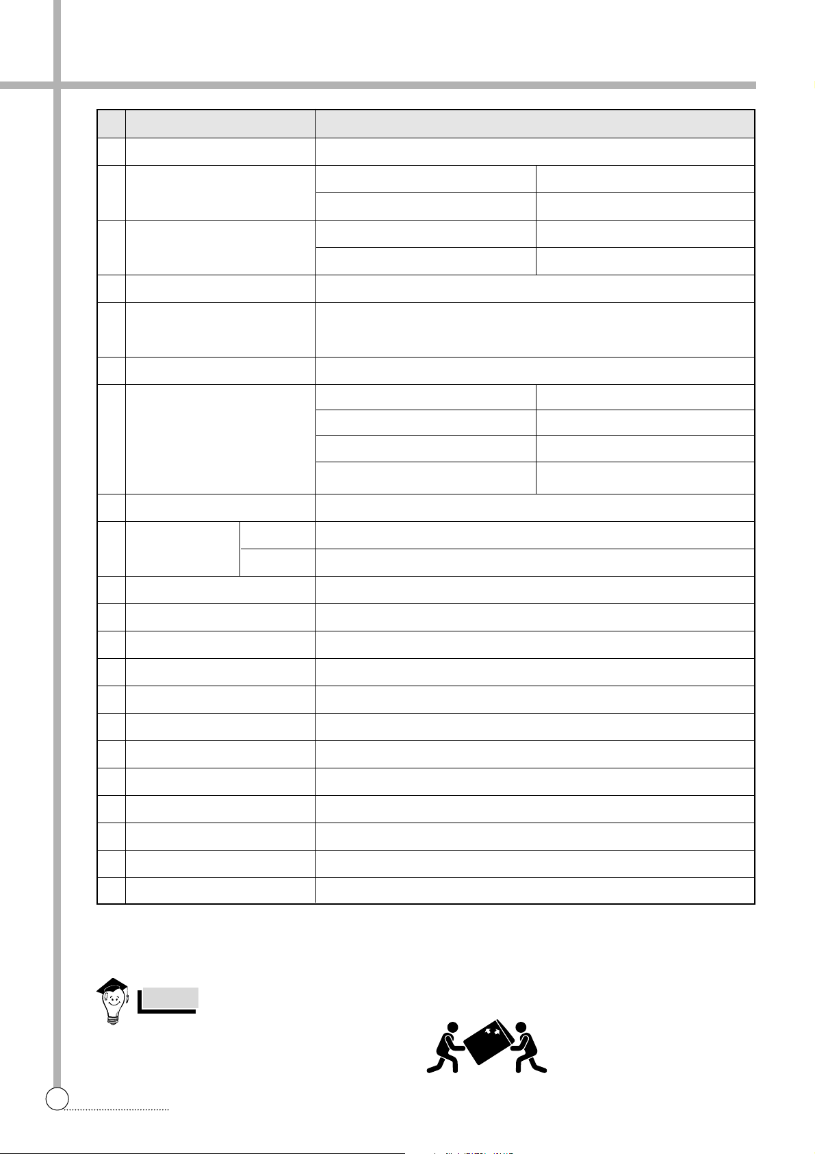
SPECIFICATIONS
NO. ITEM DWF-200A
1 POWER SOURCE AVAILABLE IN ALL LOCAL AC VOLTAGE AND CYCLE
2 POWER CONSUMPTION
3 MACHINE WEIGHT
4 DIMENSION (WXHXD)
5 WASHING COURSE
6 WATER CONSUMPTION
7 WATER LEVEL SELECTOR
8 OPERATING WATER PRESSURE 0.3kgf/cm
2
~8kgf/cm
2
(2.94 N/cm2~78.4N/cm2)
50Hz
60Hz
10 PULSAT OR 6 WINGS (Ø406mm)
11 WATER LEVEL CONTROL ELECTRONICAL SENSOR
12 GEAR MECHANISM ASS’Y HELICAL GEAR
13 LINT FILTER O
14 SOFTENER INLET O
15 FUNCTION FOR SOAK WASH O
16 ALARM SIGNAL O
17 RESIDUAL TIME DISPLAY O
18 AUTO. WATER SUPPLY O
19
FUNCTION FOR BUBBLE AND RADICAL
O
20 AUTO RE-FEED WATER O
21 AUTO POWER OFF O
50Hz
60Hz
480W
550W
NON-PUMP
47Kg
PUMP
48Kg
FULL AUTOMA TIC 6 COURSE
(FUZZY, HEAVY, BLANKET, LIGHT , ECONOMIC, DELICATE)
630 X 1070 X 670
250 L
HIGH 97 L
MEDIUM 77 L
LOW 62 L
E.LOW 56 L
WASH : 125 - 140 RPM, SPIN : 640 - 675 RPM
WASH : 130 - 150 RPM, SPIN : 710 -740 RPM
* : POUR DIRECTLY INT O TUB AFTER FINAL RINSE.
REVOLUTION
PER MINUTE
In case of moving Washing Machine, please
follow the following picture.
NOTES
Page 4
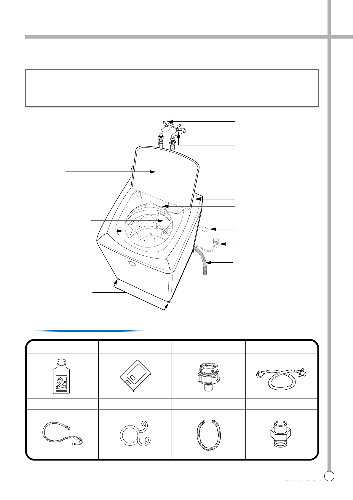
DRYTEN [OPTION]
HOSE DRAIN [FOR PUMP]
COVER UNDER (OPTION)
HOSE DRAIN CLAMP
WA TER TAP ADAPTER
HOSE DRAIN[FOR NONPUMP]
INLET HOSE
CONNECTOR INLET [OPTION]
2. STRUCTURE OF THE WASHING MACHINE
3
STRUCTURE
• HOT WATER TAP
• COLD WATER TAP
After using the washer,
close the water tap, In case
of the single valve model,
there is no hot water valve.
After using the washer,
close the water tap
• CASE DETERGENT
AND SOFTENER
• BLEACH INLET
• ADJUSTABLE LEG
• CONTROL PANEL
• HOSE DRAIN
• POWER CORD
In case of 3-wire power cord
ground wire will not be provided
• GROUND WIRE(OPTION)
• LINT FILTER(2EA)
• DOOR
A ccessories (Full Option)
The parts and features of your washer are illustrated on this page.
Become familiar with all parts and features before using your washer.
NOTE
• The drawings in this book may vary from your washer model.
They are designed to show the different features of all models covered by this book,
Your model may not include all features.
DRYTEN
UP
Page 5
3. DIRECTIONS FOR INSTALLATION AND USE
4
DIRECTIONS
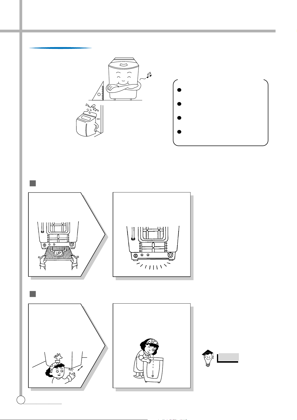
The openings must not
be obstructed by carpeting when the washing
machine is installed on a
carpeted floor.
Installation Of The Noise Inulation Plate
How To Install On An Inclined Place
The place where it would be exposed to
direct sunlight.
The place nearby a heater or heat appli-
ance.
The place where it would be supposed
to be frozen in winter.
The kitchen with coal gas and a damp
place like a bathroom.
NOTES
Install the washer on a horizontal
solid floor. If the washer is installed
on an unsuitable floor, it could make
considerable noise and vibration.
Installing Place
Never install in these places
2
Push the noise insulation plate
into the end, which decrease
the noise made by this washer.
1
The packing box
opened, there is a
noise insulation plate
at the bottom of the back
2
Check the Horizon
Status
Check the position of tub above
the center of the washer.
1
Horizon
Setting
After controlling the height
by turning the adjustable
leg, let the washer put
down to the ground.
Keep the machine body
more than 25cm apart from
the wall surface. It will
make easy cleaning the
drain filter which is equipped
at the back side of it. And if
it comes into contract vibration may occur.
10Cm
Page 6
5
CONNECTION
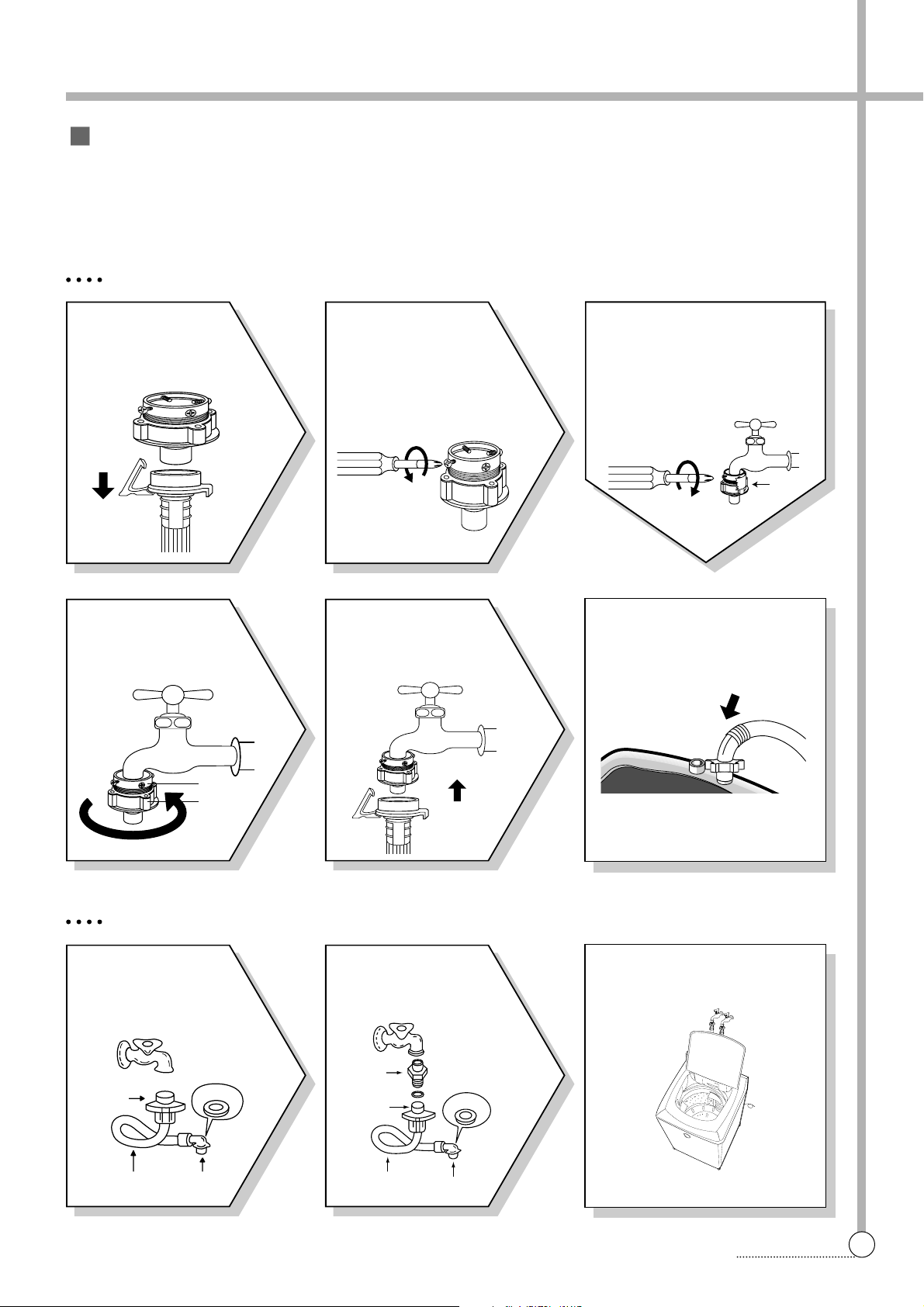
FOR ORDINARY TAP
6
Connect the inlet hose adapter
of the hose to the water inlet of
the washer by turning it clockwise to be fixed tightly.
• Please check the rubber packing
inside the inlet hose adapter of
the hose.
1
Pull down the collar
of the inlet hose to
separate it from the
water tap adapter.
2
Loosen the four
screws at the water
tap adapter, but don’t
loosen the screws until
they are separated from
the water tap adapter.
4
Remove the tape,
and screw connector
B into connect A tightly.
5
Connect the inlet
hose to the water tap
adapter by puling down
the collar of the hose end.
3
Connect the water tap
adapter to the water tap tighten the four screws evenly
while pushing up the adapter
so that the rubber packing
can stick to the water tap
tightly .
How to Connect the Inlet Hose
Be careful not to mistake in supplying between the hot(maximum : 50˚C) and cold water.
In using only one water tap or in case of attached one water inlet valve, connect the inlet hose to the cold water inlet
valve.
Do not over tighten : this could cause damage to couplings.
FOR SCREW-SHAPED TAP
3
Insert the inlet hose adapter
into the water inlet of a washer
and turn it to be fixed.
• Check the packing in the inlet
1
Connect the inlet
hose to the water tap
by screwing the connector D tightly.
2
Connect the connector-inlet supplied if
necessary .
Inlet Hose
Connector D
Rubber
Packing
Connector C
Connector
Inlet
Rubber
Packing
Connector D
Connector C
Hose
TAPE
Connector B
Connector A
Page 7
6
CONVENIENCE
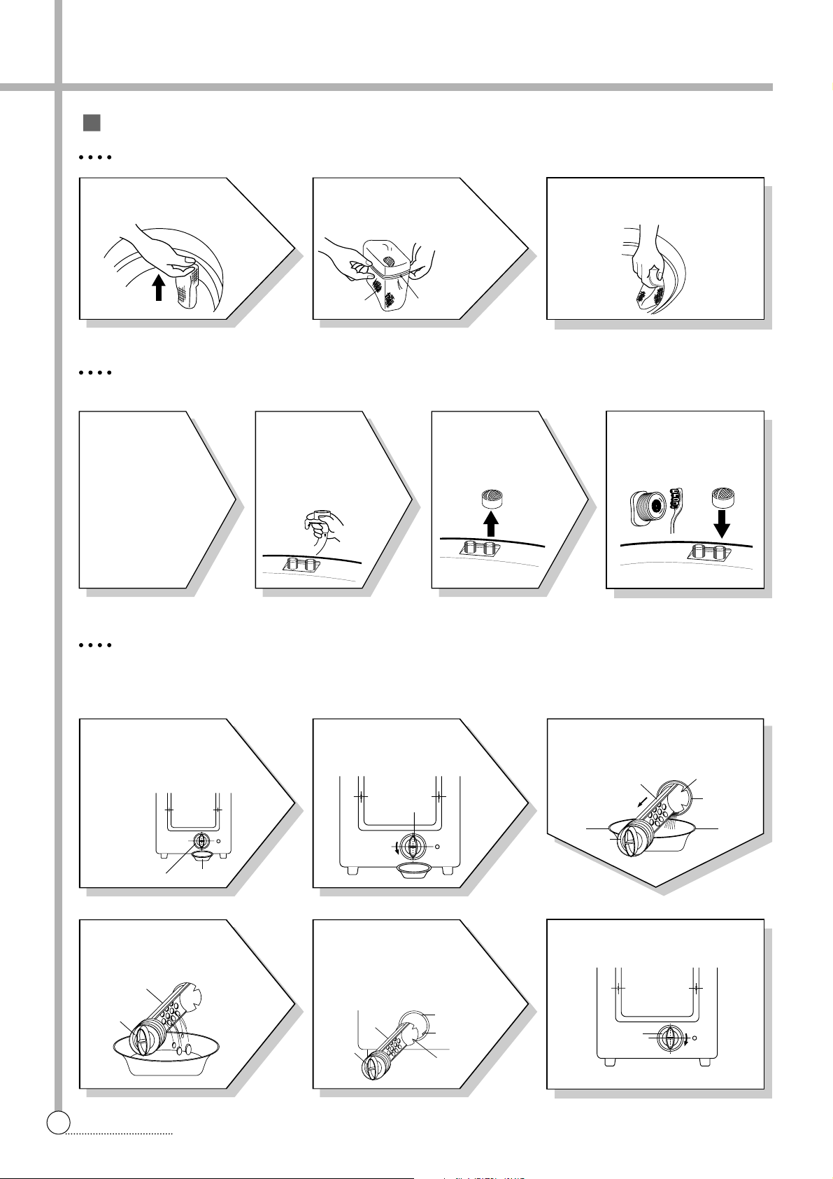
How To Clean The Filter
4
Remove the dirt
from the inlet filter
with a brush.
1
Pull the
power plug
out before
cleaning it.
2
Turn off the
water supply
to the washer
and sperate the
inlet hose.
3
Pull the
inlet filter out.
CLEANING THE LINT FILTER
CLEANING THE WATER INLET FILTER
• Clean the filter when water leaks from, the water inlet.
CLEANING THE DRAIN FILTER
• In case “U” shape drain hose, this filter’s equipped at the back side of washer.
• This drain filter is to screen the foreign stuffs such as threads, coins, pins, buttons etc ...
• If the drain filter is not cleaned at proper time (every 10 times of use), Drain problem could be caused.
3
Return the filter as it was, and
insert the filter frame into the
slot.
1
Pull the Filter frame
upward.
2
Turn the lint filter
inside out, wash to
the lint off with water.
1
Put down the
remained water in the
hose. And put a container
under the filter to collect
water.
2
Turn the cap counter
clockwise.
3
Pull out the filter assembly off
the case of the main body.
6
Turn the cap clockwise tightly.
4
Clean the drain filter
removing the foreign
stuffs.
5
Put in the filter along the
guiding prominence of the
case. Please note the left
position of the filter adjusting
the groove to the guide rib.
FILTER
CONTAINER
CAP
SLIT
CASE
FILTER
CAP
CAP
FILTER
CAP
FILTER
CASE
GUIDE
RIB
SLIT
CAP
Filter Frame
Lint Filter
Page 8
4. FEATURE AND TECHNICAL EXPLANATION
7
FEATURE
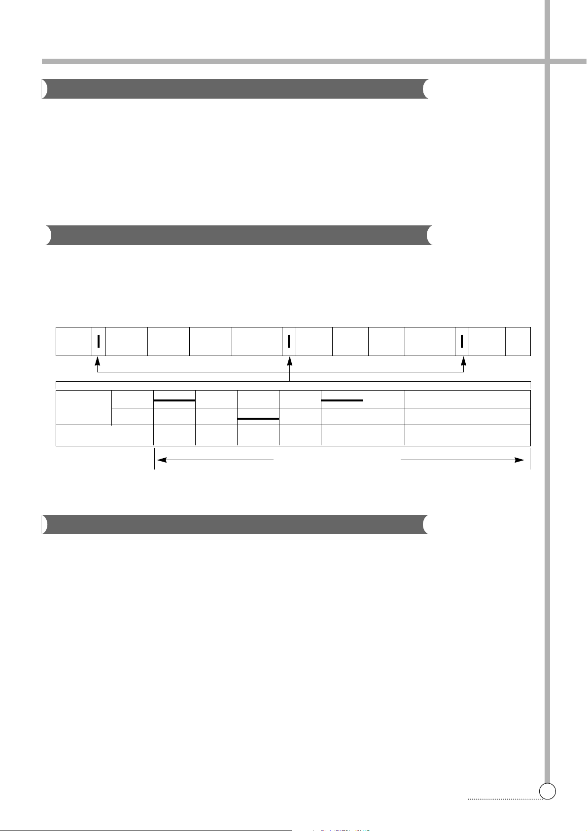
WASH DRAIN SPIN FILL RINSE 1 DRAIN SPIN FILL RINSE 2 DRAIN •••
MOTOR C.W
SINGAL C.C.W
TIME(SEC.) 0.3 0.3 0.3 0.3 0.3 0.3 •••••••
35 SEC. (About 29 Times)
Feature of the Washing Machine
1 First applying the Radical Technology in the world ... go beyond washing, sterilize your colthes and deodorize a bad
smell.
2 The first air bubble washing system in the world.
3 Quiet washing through the innovational low-noise design.
4 Improving washing performance by more than 35%, while reducing power consumption by 40%.
5 The laundry detergent dissolves well in water because of the air bubble washing system.
6 The adoption of the water currents to adjust the unbalanced load.
7 One-touch operation system.
Water Current to Adjust the Unbalanced Load
It is a function to prevent eccentricity of the clothes after wash by rotating pulsator C.W and C.C.W for 35
seconds.(But, the SUIT course have no operation of the water currents to adjust the unbalnced load.)
EFFECT
It reduces vibration and noise effectively while spinning.
WATER FLOW
Automatic Water Supply System For Blanket Wash
The water level would be lowered because the blanket absorbs water at the beginning of washing. Therefore, after
2 minutes, the operation is interrupted to check the water level, and then the water is supplied again until the selected water level is reached.
Page 9
8
FEATURE
FUNCTIONAL PRINCIPLE
1 The micom can remember the time from the begining of drain to reset point when the pressure switch reaches to
“OFF” point
2 In case of continuous draining, residual drain time is determined by micom.
Draining time as a whole = D + 90
Residual drain time.
The time remembered by micom.
FUNCTIONAL PRINCIPLE
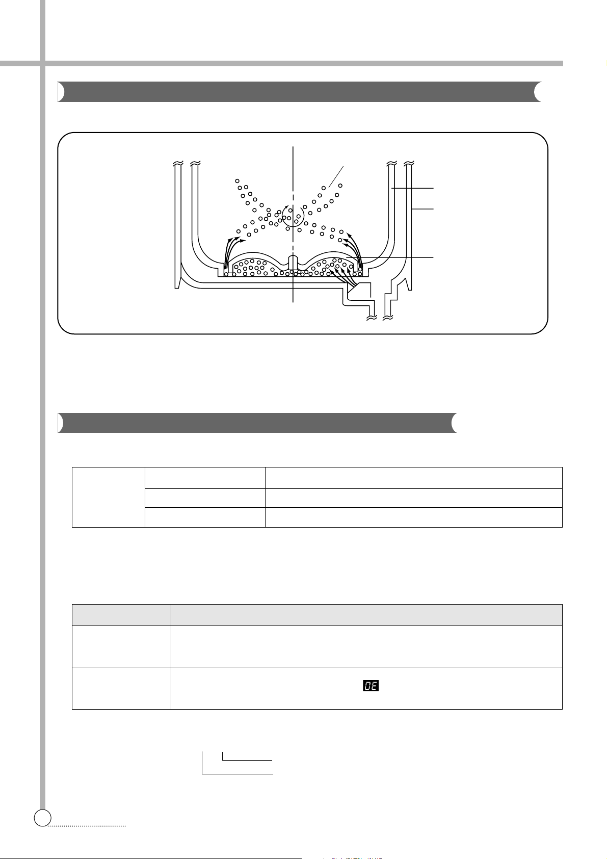
Bubble Motor supplies the air from the bottom of outer tub to the inner space of pulsator, the air is dispersed by the
rotation of pulsator. Air-bubble is created by the centrifugal force, and rises up.
Draining
Good draining The washer begins spin process after drainage.
condition
Bad draining Draininig time is prolonged.
No draining Program is stopped and gives the alarm.
Drain Time Movement of the Program
Less than
Continue draining
15 minutes
More than
Program stops and gives the alarm with blinked on display lamp.
15 minutes
Functional Principle of Bubble Washing Machine
ACROSS SECTION
Automatic Drainning time Adjustment
This system adjusts the draining time automatically according to the draining condition.
Air bubble
Tub
Outer tub
Pulsator
Page 10
9
FEATURE
Automatic Unbalance Adjustment
Circulating-Water Course and Lint Filter
The alarm finished when you close the lid after opening
it. Check the unbalance of the wash load and the installation condition.
NOTES
Filter
Tub
Outer tub
Water
channel
Pulsator
This system is to prevent abnormal vibration during intermittent spin and spin process.
FUNCTIONAL PRINCIPLE
1 When the lid is closed, the safety switch con-
tact is “ON” position.
2 In case that wash loads get uneven during
spin, the outer tub hits the safety switch
due to the serious vibration, and the spin
process is interrupted.
3 In case that P.C.B. ASS’Y gets “OFF” signal
from the safety switch, spin process are
stopped and rinse process is started automatically by P.C.B. ASS’Y.
4 If the safety switch is operated due to the
unbalance of the tub, the program is
stopped and the alarm is given.
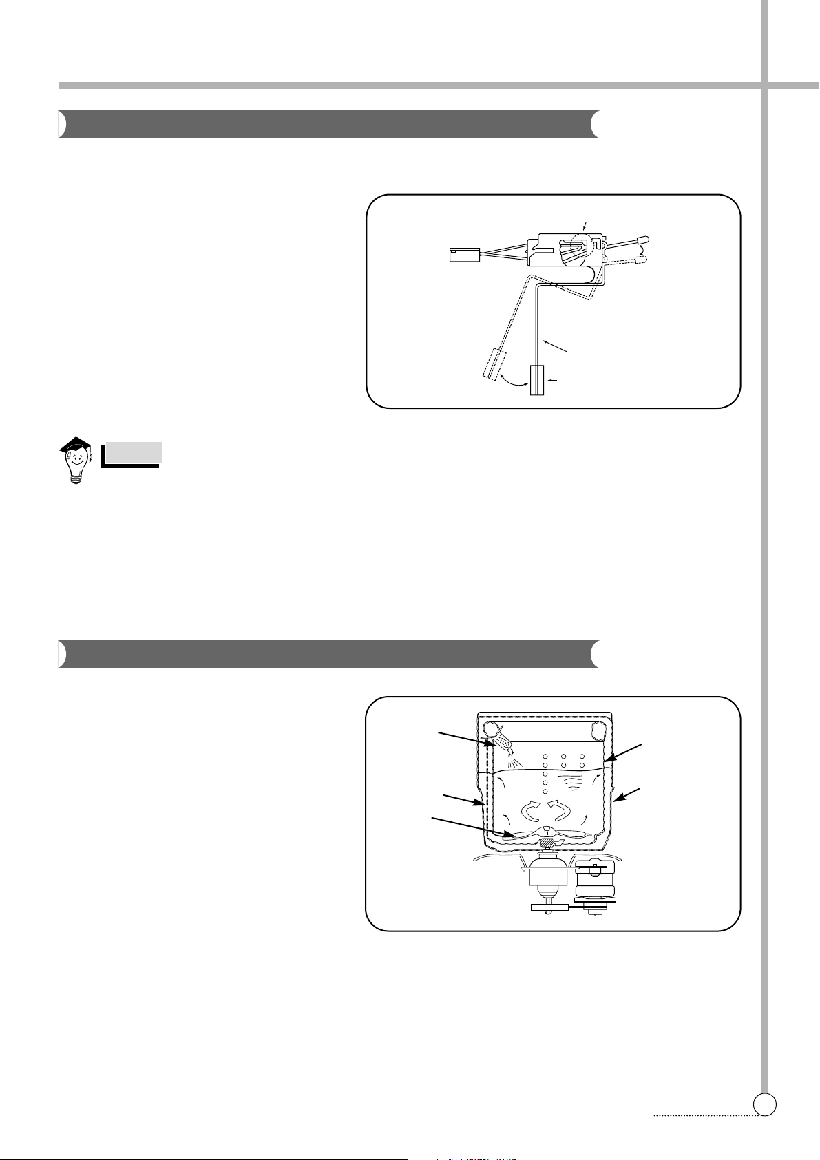
CIRCULATING-WATER
The washing and rinsing effects have been
improved by adopting the water system in
which water in the tub is circulated in a
designed pattern.
When the pulsator rotates during the washing
or rinsing process, the water below the pulsator fans creates a water currents as shown
in figure.
The water is then discharged from the upper
part of the tub through the water channel.
About 40 L/min. water is circulated at the ‘high’
water level, standard wash load and standard
water currents.
Position of
unbalanced load (OFF)
Contact of safety switch Lid closing
Lid opening
Contact lever A
Normal (ON)
Page 11
10
FEATURE
Much lint may be obtained according to the kind of
clothes to be washed and some of the lint may also
sticks to the clothes.
To minimize this possibility a lint filter is provided on
the upper part of the tub to filter the wash water as it
is discharged from the water channel. It is good to
use the lint filter during washing.
HOW TO REPLACE LINT FILTER
1 Pull the filter frame upward.
2 T urn the lint filter inside out, and wash the lint off with water.
3 Return the filter as it was, and fix the filter frame to the slot.
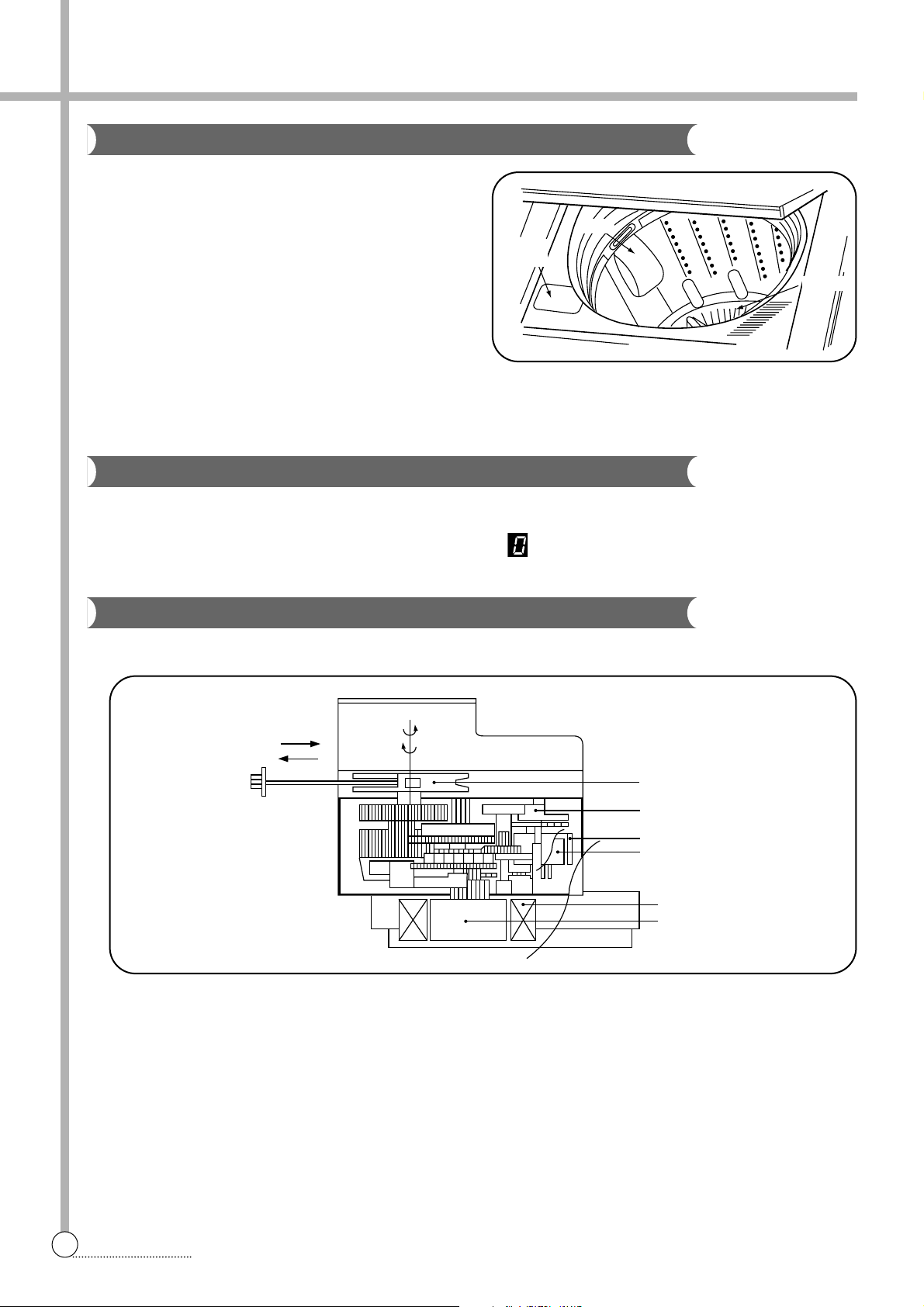
When the START/HOLD button is pressed, the residual time (min.) is displayed on the time indicator, and it will be
counted down according to process.
When operation is finished, the TIME INDICAT OR will light up .
STRUCTURE
FUNCTIONAL PRINCIPLE
1 When the DRAIN MOTOR connected to the power source, the DRAIN MOTOR rotates with 900 r.p.m and revolves
the pulley by gear assembly for reducing.
2 When the pulley is rotated, the pulley winds the wire to open the drain valve.
3 Therefore, rotation of pulley changed to the linear moving of wire.
4 The wire pulls the brake lever of Gear Mechanism Ass’y within 5 seconds.
5 After the wire pulled, gear assembly is separated from motor and condition of pulling is held by operation of the
lever.
6 When the power is turned off, the drain valve is closed because the wire returns to original position.
Bleach Inlet
Filter
Pulsator
Pull
Loosen
Pulley
Lever
Inductive ring
Magnet
Coil of motor
Magnet of motor
Lint Filter
Residual Time Display
Drain Motor
Bleach
Inlet
Filter
Pulsator
Page 12
11
FEATURE
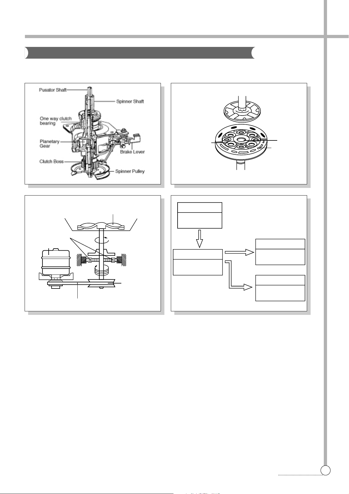
The proper water currents is made by the rotation of pulsator at a low speed to prevent the damage to the small
sized clothes.
Planetary gear
Sun gear
Internal gear
Pulsator
1 revolution
5 revolutions
Gear pulley
V-belt
Gear unit as
Motor
Motor
1800 r.p.m (60Hz)
1500 r.p.m (50Hz)
Gear Unit as
Directly
V.BELT
Tub
710-740r.p.m(60Hz)
640-675r.p.m(50Hz)
Pulsator
125-140r.p.m(60Hz)
130-150r.p.m(50Hz)
Spinner Pulley
710-740r.p.m(60Hz)
640-675r.p.m(50Hz)
Gear Mechanism Ass y
Page 13
5. DIRECTIONS FOR DISASSEMBLY AND ADJUSTMENT
12
DIRECTIONS
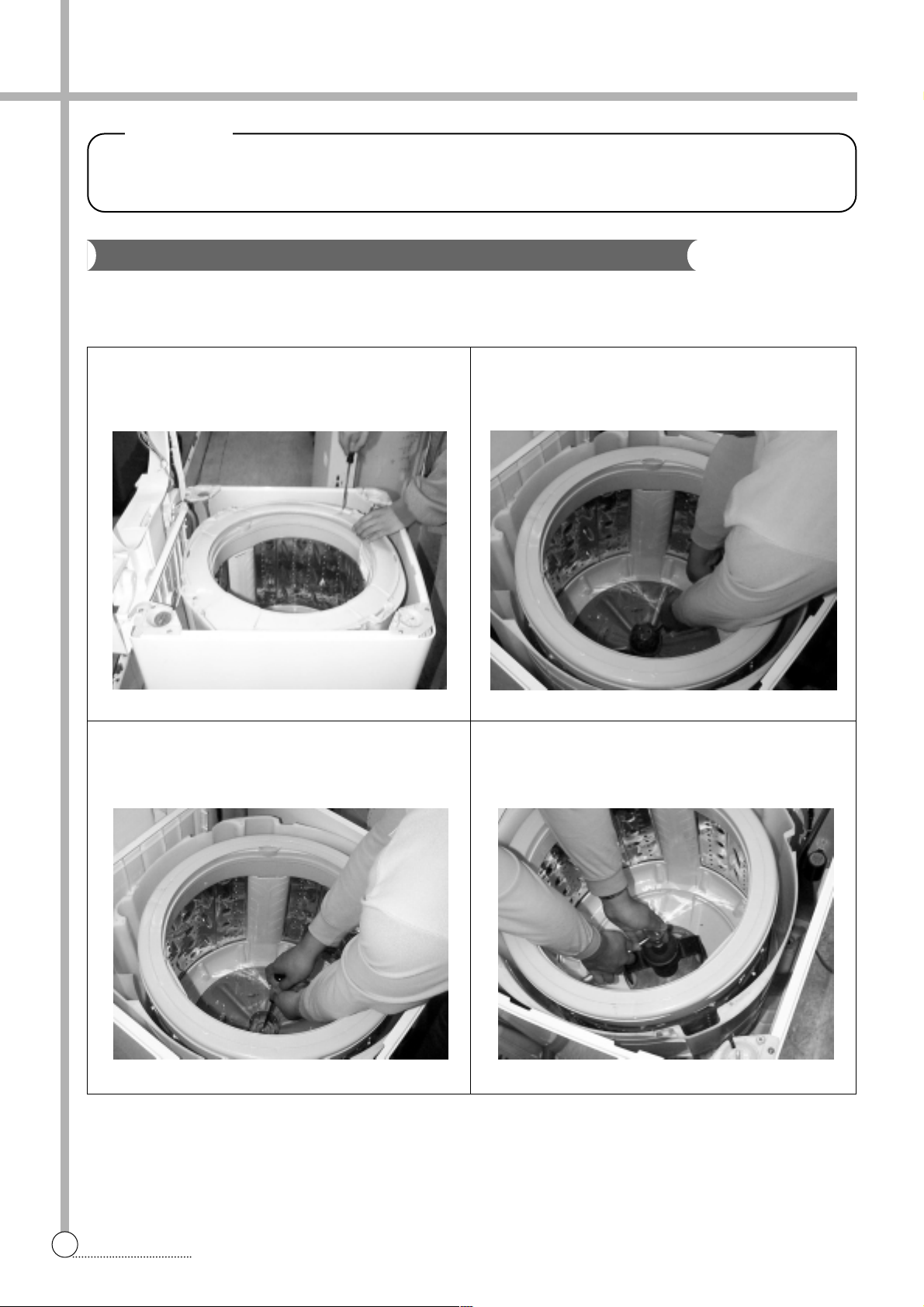
Gear Mechanism Ass y Replacement
BEFORE ATTEMPTING TO SERVICE OR ADJUST ANY PART OF THE WASHING MACHINE, DISCONNECT
THE POWER CORD FROM THE ELECTRIC OUTLET.
Warning
1 Raise the top plate on the outer cabinet.
2 Loosen four screws mounting outer tub cover and
remove outer tub cover from the tub ass’y.
4 Loosen the pulsator mounting screw and remove the
pulsator.
3 Remove the cap pulsator from the pulsator assy by
using screw driver
5 Remove the special nut by using “T” type box wrentch.
6 Remove the special washer.
GEAR MECHANISM ASSY REPLACEMENT
Page 14
13
DIRECTIONS
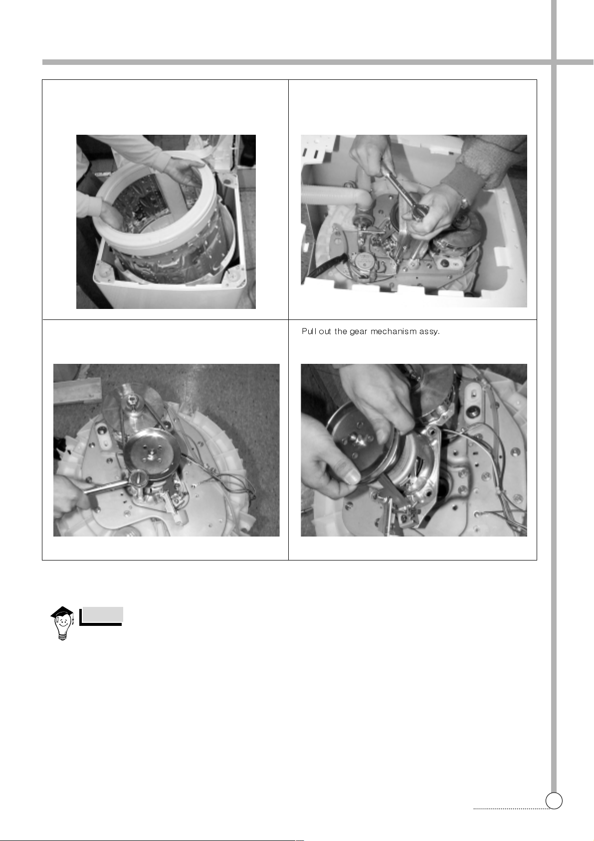
To assemble the gear mechanism ass’y, reverse the disassembly procedure.
NOTES
7 Remove the tub i assy.
q Remove four special bolt of gear mechanism assy by
using a box wrentch.
8 Lay the front of the washer on the floor.
9 Remove four special bolts of gear protect by using a box
wrentch and remove gear protect.
0 Remove the V-belt.
w
Page 15
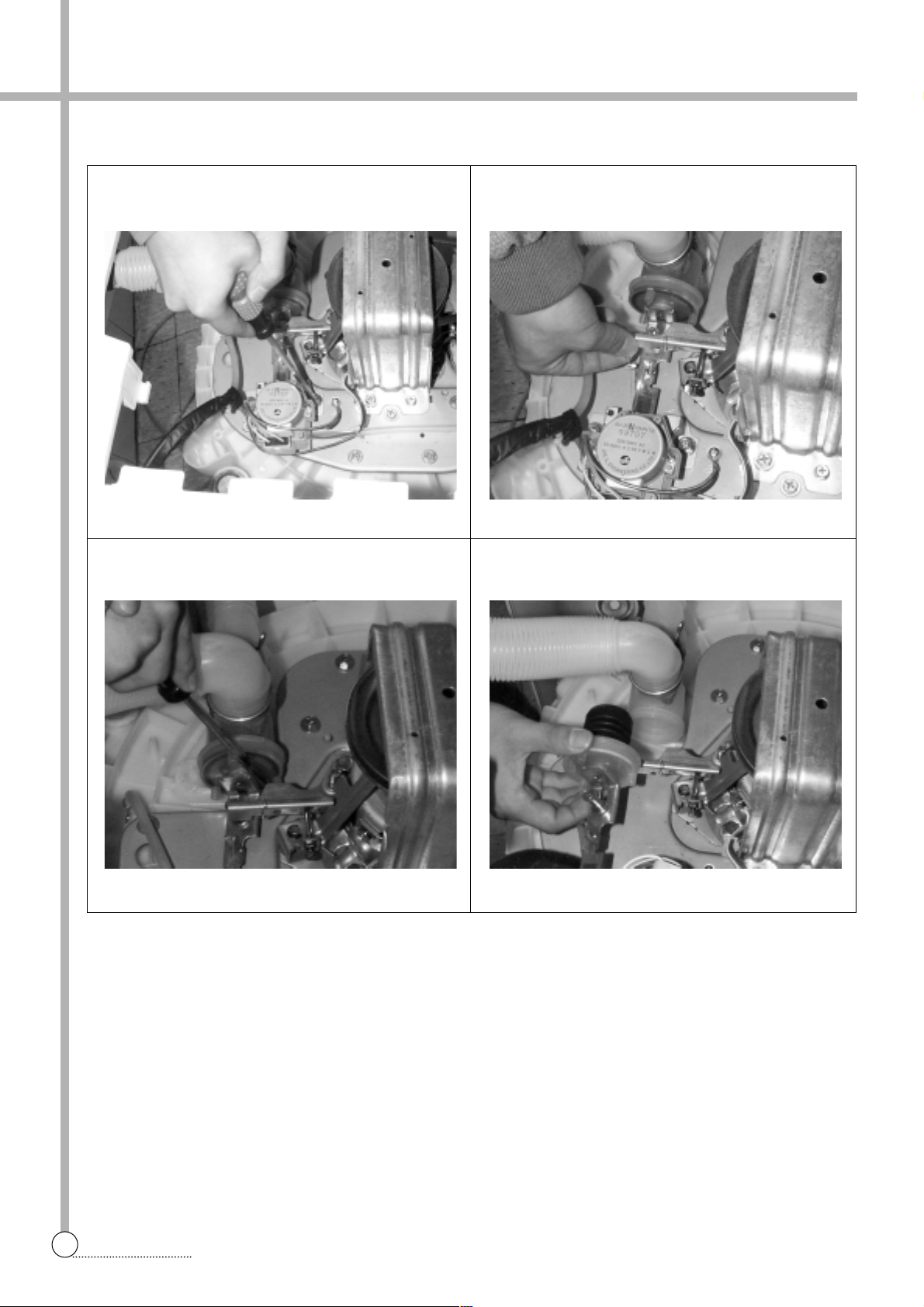
14
DIRECTIONS
1 Lay the front of the washer on the floor.
2 Loosen two special screw of motor synchronous.
5 Turn the valve by using screw driver as shown in picture.
3 Take out the wire of motor synchronous from the braket.
4 Separate the motor synchronous from the base.
6 Remove the valve lid from the valve drain assy.
MOTOR SYNCHRONOUS AND V ALVE REPLACEMENT (NON PUMP MODEL)
Page 16
15
THE REPAIR
6. THE REPAIR METHOD OF GEAR MECHANISM FOR CLUTCH SPRING PROBLEM
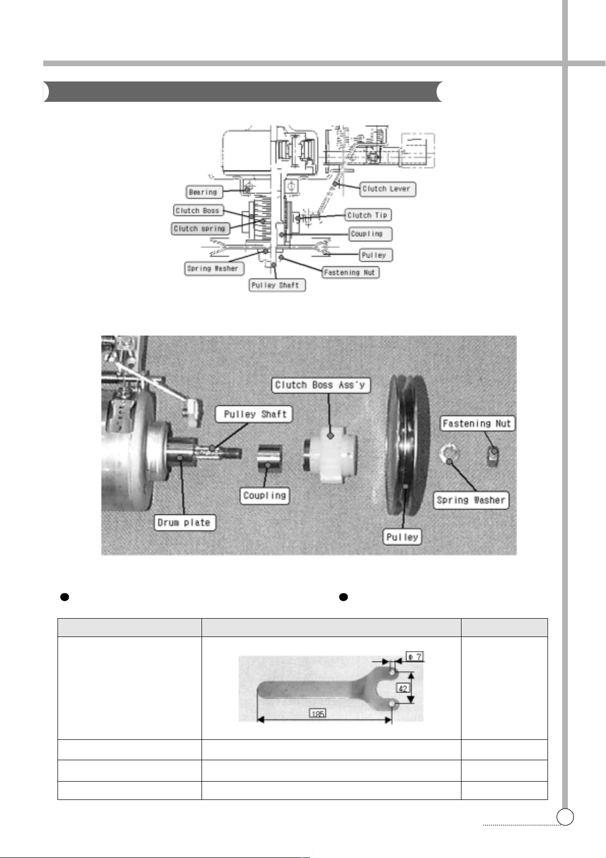
TOOL FOR REPLACING THE CLUTCH BOSS ASSEMBLE
Tool name Specification Q’ty
Fixing jig 1
Ratchet handle 1
Socket and extension bar socket : 10mm, 17mm per each
Some cotton yarn some
TheS tructure O f G e ar M echanism
Page 17
16
THE REPAIR
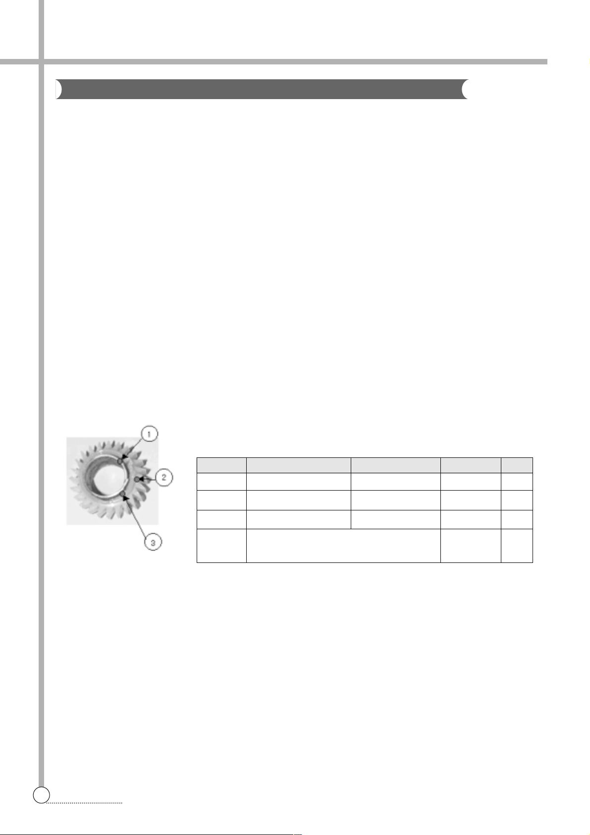
NO. P AR TS NAME SPECIFICA TION CODE Q’TY
1 CLUTCH SPRING 1.5*1.5 36151 10000 1
2 CLUTCH BOSS PP 3619301300 1
3 GREASE beacon#325 3g
P ACKING PACKING THE CLUTCH BOSS ASS’Y1
METHOD BY USING VINYL P ACK
1) THE LAUNDARY IS IN THE SPIN TUB UNEVENL Y WHEN JUST STARTING SPIN PROCESS.
2) THEREFORE, IT CAUSE THE SERIOUS NOISE AND VIBRATION WHEN WASHING AND SPINNING
PROCESS OR SUPPLING WATER IRREGULARY WHEN SPINNING PROCESS
AND CAUSE SHORT OF SPIN PERFORMANCE.
IN THIS CASE, YOU MUST EMPTY THE SPIN TUB FIRST.
1) TO CHECK THE REVOLUTION OF SPIN TUB. IF THE SPIN TUB DOES NOT REVOL VE AND ONLY
THE PULSA T OR IS TURNING, THAT IS CLUTCH SPRING DEFECT.
2) TO CHECK THE SPIN SPEED(RPM) BETWEEN SPIN TUB AND PULSA T OR.
IF YOU FIND THE DIFFERENT SPIN SPEED BETWEEN SPIN TUB AND PUSATOR, THIS IS ALSO
CLUTCH SPRING DEFECT.
IN THIS CASE, WE ARE GOING TO SUPPL Y THE CLUTCH BOSS ASSEMBLY INSTEAD OF GEAR
MECHANISM ASSEMBLEY. PLEASE REFER TO FOLLOWING FIG.
PROBLEM
CHECKING METHOD
THE CLUTCH BOSS ASSEMBLY
CLUTCH BOSS ASS’Y PART CORD : 3619301400
H o w To C heck The C lutch S pring Problem
Page 18
17
THE REPAIR
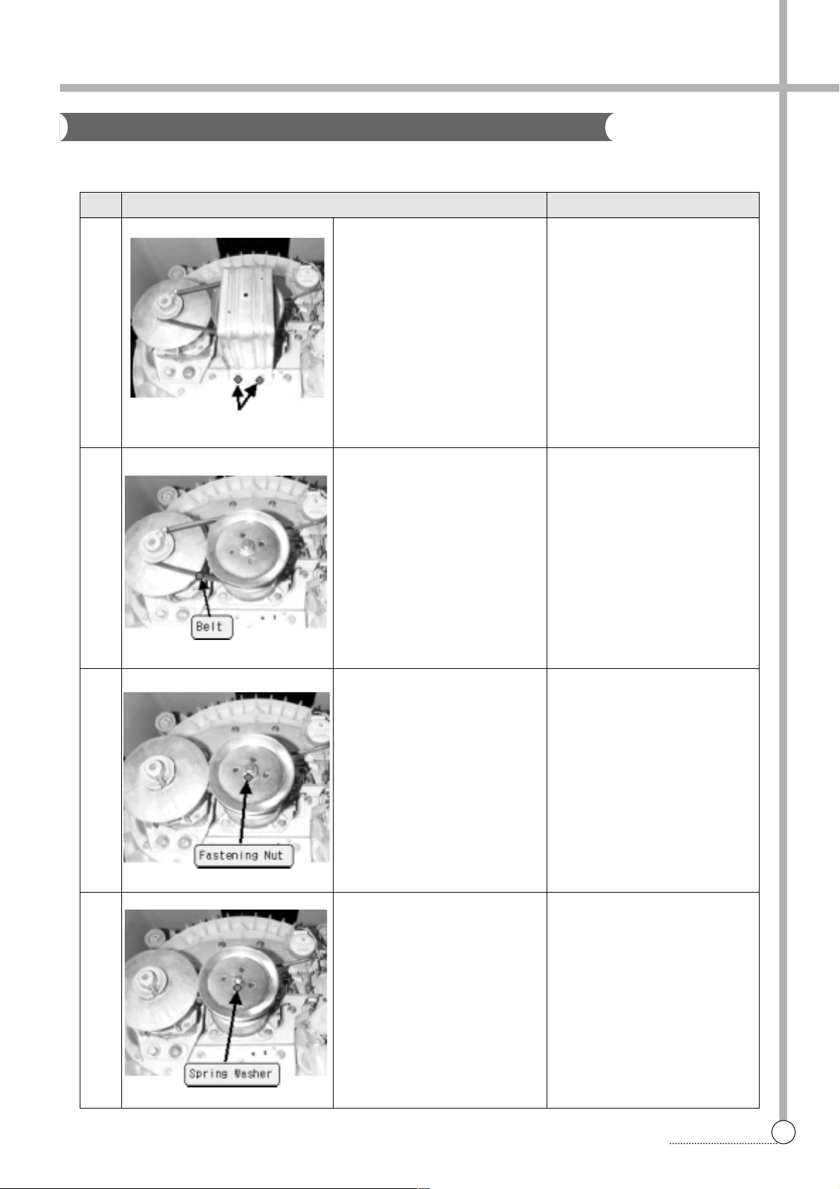
No. Process Notice
Disassemble 1
1
2
3
4
Release screws marked 4-point
Remove the protector
Remove the v-belt
Loosen the fastening nut
Disassemble the spring washer
Use wrench or driver
- ratchet handle
- extension bar
- socket : 10mm
Use fixing jig for pulley as to
see fig 1.
and 17mm-socket for nut
Take out plain washer if it has
The Process Of Disassemble
Page 19
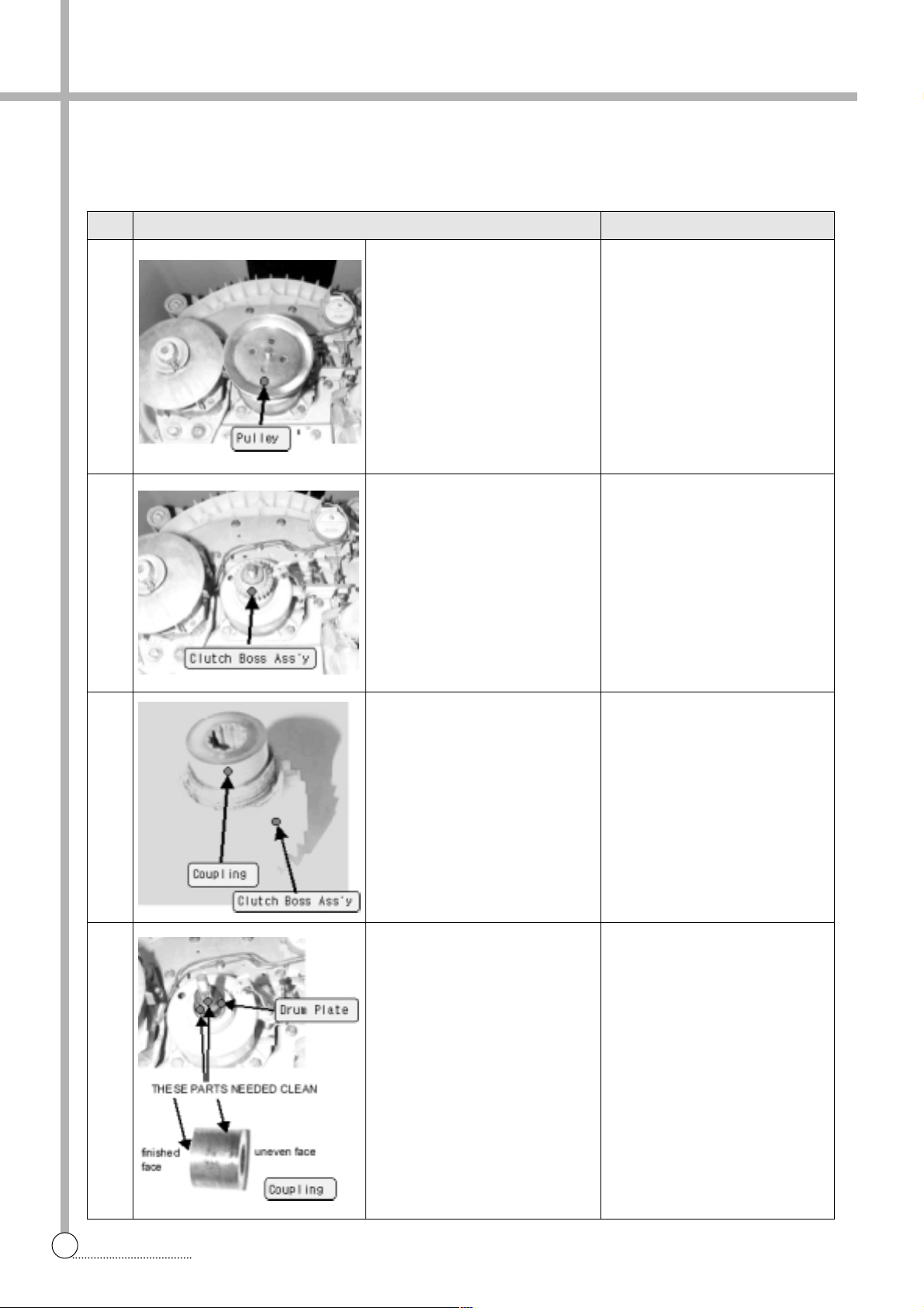
18
THE REPAIR
No. Process Notice
Disassemble 2
5
6
7
8
Disassemble the pulley
Disassemble the clutch boss
assembly
Separate coupling from clutch
boss ass’y
Cleaning
Catch the boss and pull
upward with spiral rotate in the
clockwise direction
Clean the drum plate, coupling
surface and contact face
between drum plate and coupling
It is necessary to keep cotton
piece goods being dry and
clean
Page 20
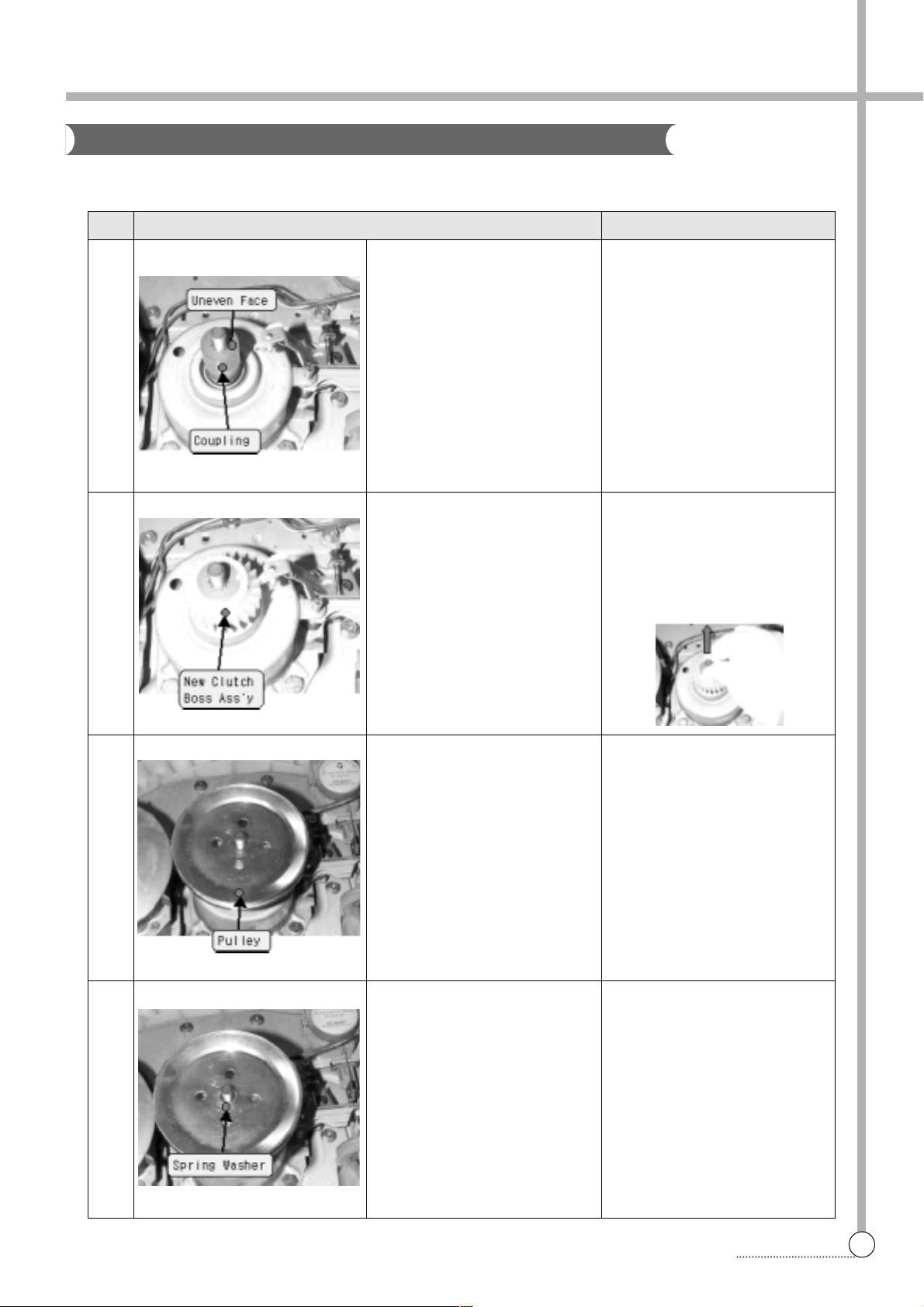
19
THE REPAIR
No. Process Notice
Assemble 1
1
2
3
4
Assemble the coupling
Assemble the new clutch boss
ass’y
Assemble the pulley
Assemble the spring washer
Check the uneven face of coupling is assembled upward
- Push in the clutch boss ass’y
with rotating on the clockwise
direction.
-
After assembling, rotate on the
clockwise more 2~3 teeth and
pull out the pulley shaft upward
If there was plain washer, you
have to assemble plain washer
the first and then assemble
spring washer
The Process Of Assemble
Page 21
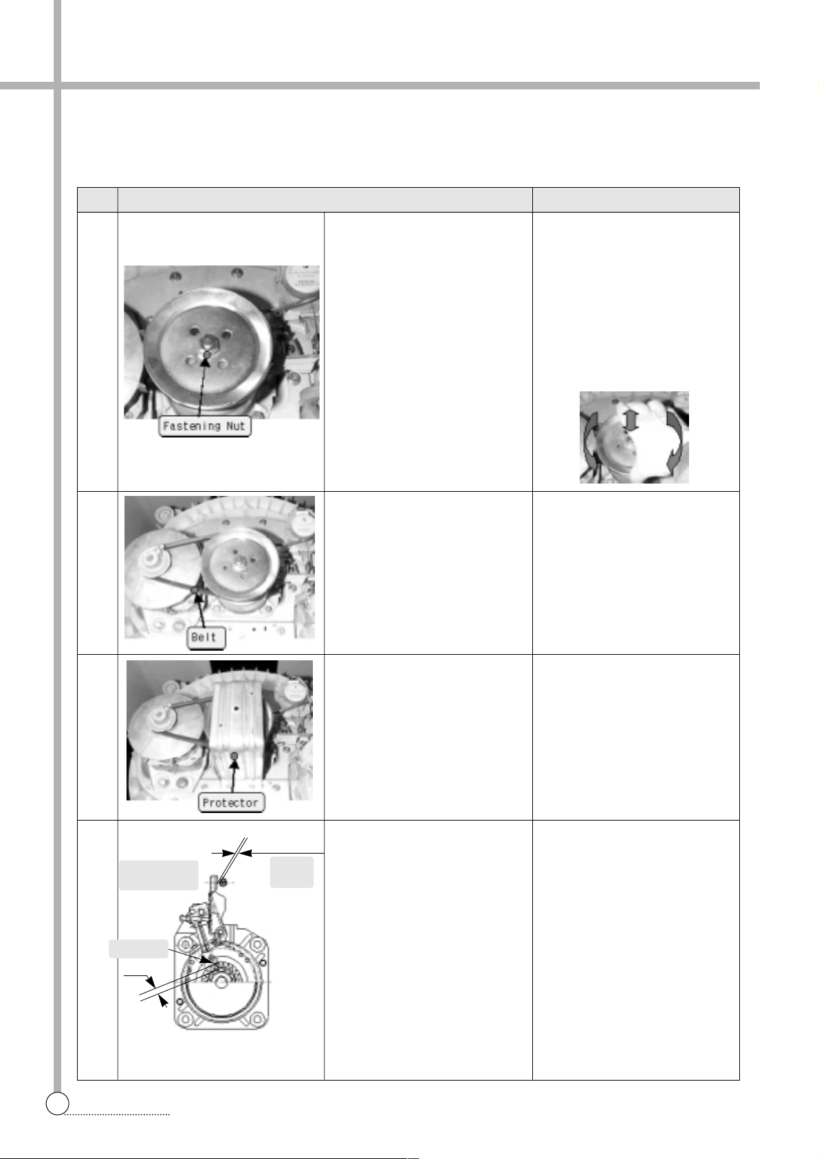
20
THE REPAIR
No. Process Notice
Assemble 2
5
6
7
8
Clutch Tip
Drain
V alve
Synchronous
Motor
3.5~4.5
keep distance 2~3mm
Assemble the fastening nut
Assemble the Belt
Assemble the protector
Final checking
- Use fixing jig and 17mm
socket wrench
as if disassembling,
as fastening torque about
100~200kgf-cm.
- Check the end-play, up and
downward and check the binding force, too much or not on
bi-direct of rotation.
Finally , check the distance
between brake lever and control bolt. (2~3mm)
Also, check the interferance
depth both clutch tip and clutch
boss(3.5~4.5mm)
Page 22
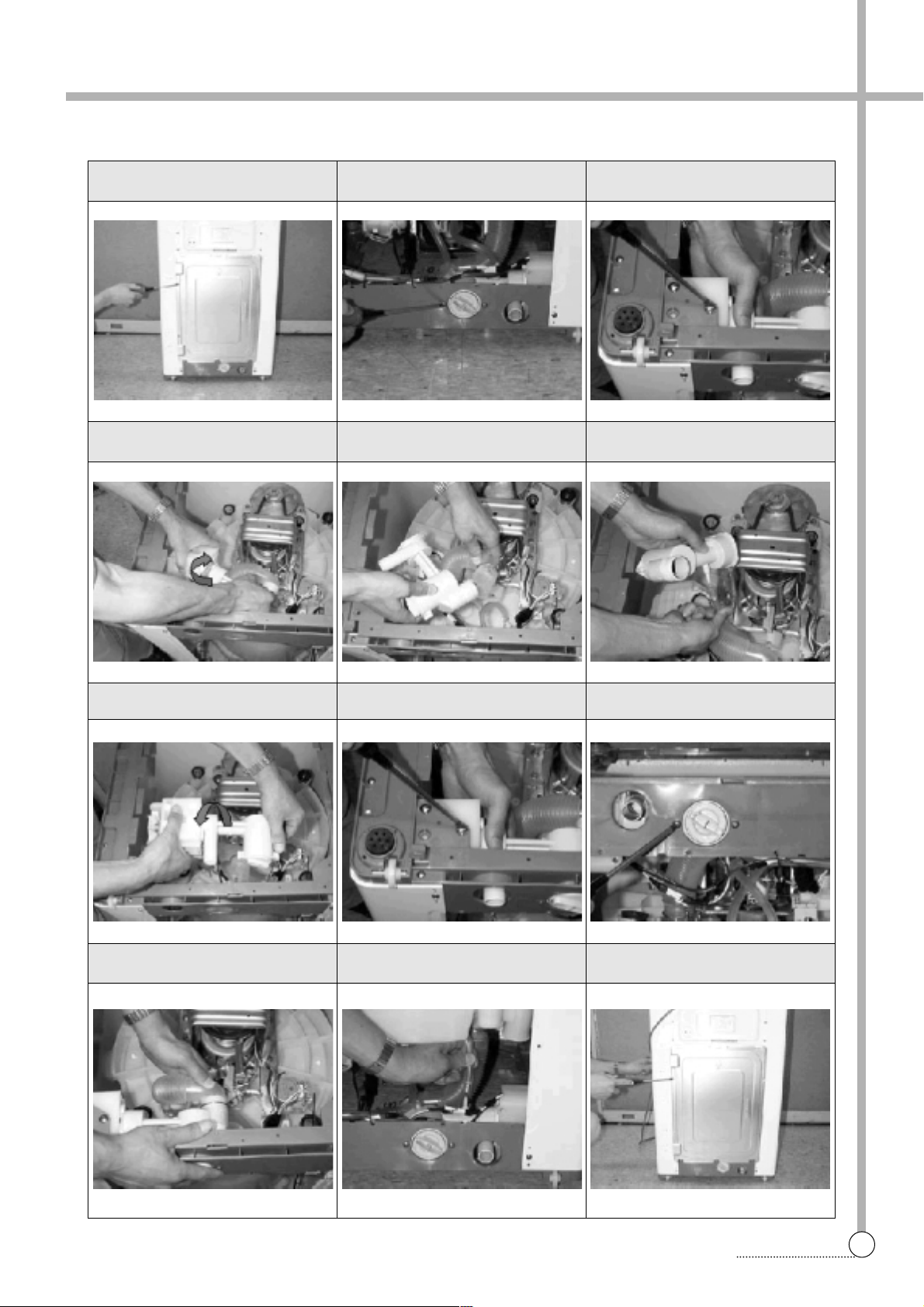
21
THE REPAIR
1 separate the back cover from
washing machine
4 turn the case filter ass’y and sepa-
rate it from the drain motor
7 assemble the case filter ass’y that
purchased
0 assemble the hose drain I to the
case filter with bond & clamp
2 remove two screws
5 separate the drain hose i from the
case filter ass’y
8 tie up three screws
q assemble the cavitation hose to
the case filter with bond & clamp
3 remove three screws
6 separate the cavitation hose from
the case filter ass’y
9 tie up two screws
w assemble the back cover to the
washing machine
REPLACE THE CASE FILTER ASS’Y
Page 23
22
TROUBLE SHOOTING
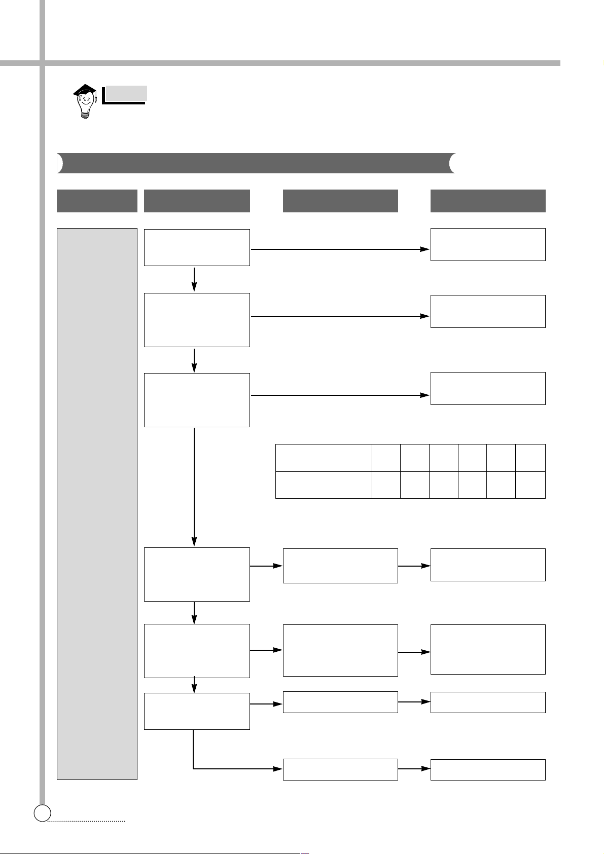
7. TROUBLE SHOOTING GUIDE
PROBLEM
WATER IS
NOT SUPPLIED.
CHECK POINT
Do you open the water
tap?
Is the filter of the water
inlet valve clogged with
dirt?
Is the water pressure
sufficient?
(0.3~8 kgf/cm
2
)
Does the water inlet
valve make operating
sound?
Is the connector or the
terminal connected
properly?
Is the output voltage of
the P.C.B normal?
CAUSE
Water inlet valve
is defective.
Improper connection of
the connector or the terminal.
P.C.B AS is defective.
Lead wire is defective.
SOLUTION
Change water inlet valve.
Open the water tap.
Clean the filter.
Increase the water pressure.
Connect the connector or
the terminal properly.
Change the P.C.B AS.
Change the lead wires.
NO
YES
NO
YES
NO
YES
YES
YES
YES
NO
NO
NO
NOTE : Open the water tap fully and measure
the flow rate.
From the upper results, you know that the flow rate more than
1 1.5l/min. is essential for water supply.
Flow
1 1.5 15.0 18.0 20.3 24.1 27.4
rate(l/min.)
Water pressure
0.3 0.4 0.5 0.6 0.8 1.0
(Kgf/cm
2
)
1. When replace the P.C.B. ASS’Y do not scratch the surface of the P.C.B. ASS’Y.
2. Disconnect the power cord from the electric outlet.
NOTES
Concerning Water Supply
Page 24
23
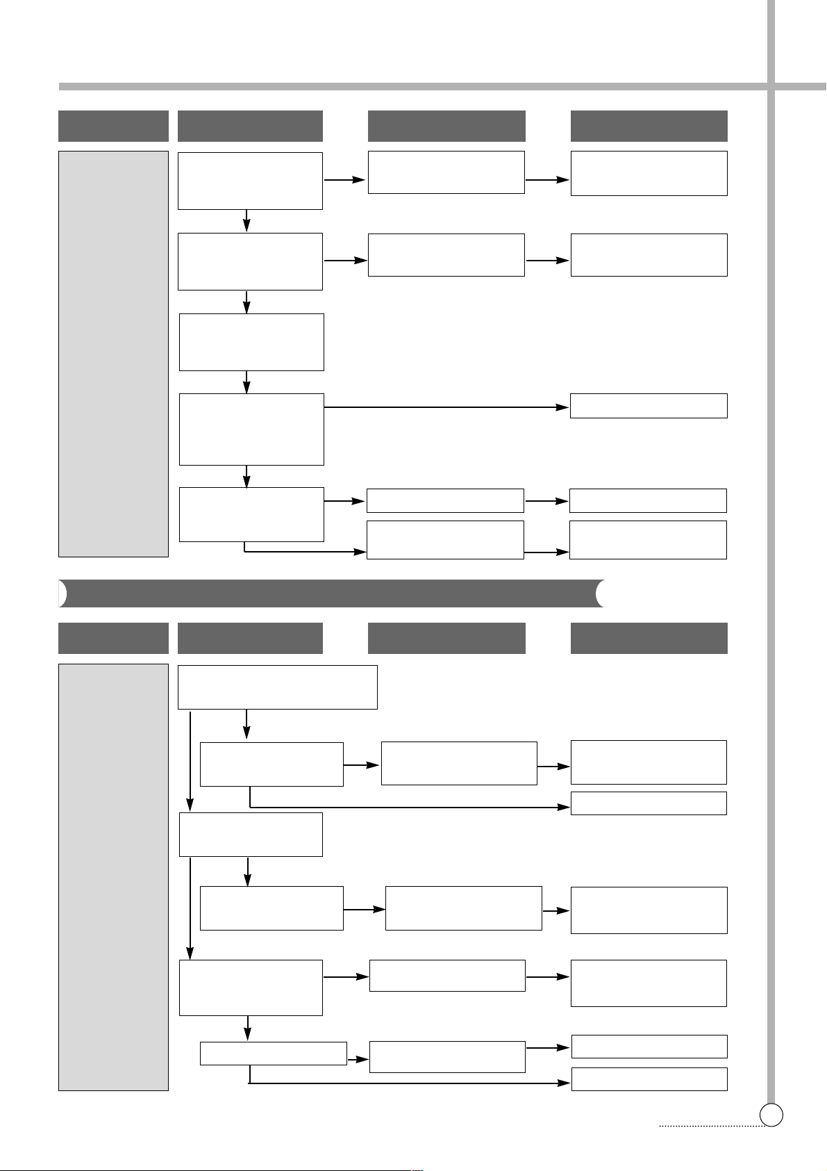
TROUBLE SHOOTING
PROBLEM
WATER SUPPL Y IS NOT
STOPPED.
CHECK POINT
Does the water supply
continue while the power
is turned off?
Does the water supply start
as soon as you press the
power switch?
Operate the washer after
setting the water level to
“HIGH”
Does the water supply
continue after the water
reaches to the “HIGH”
level?
Is the air tube of water
level switch kinked or
deformed?
CAUSE SOLUTION
Change the water inlet
valve.
The water inlet valve is
defective.
The triac of P.C.B is
defective.
Change the P.C.B ASS’Y.
Normal operation.
Change the air tube.Air tube is defective.
Change the pressure
switch.
Pressure switch is defective.
PROBLEM
THE PULSA T OR DOES
NOT ROT ATE
EVEN IF THE
WATER IS
SUPPLED.
CHECK POINT
Does the motor operate after finishing water supply?
Does the motor make
operating sound?
Is the connection condition of capacitor terminal good?
Does pulsator rotate in
only one direction?
Is the motor coil disconnected?
Is the V-belt worn out?
The triac of P.C.B is
defective.
Motor is defective.
Improper connection
V-belt is defective.
Change the P.C.B
ASS’Y.
Normal
Change the motor.
Connect the terminal
properly .
Change the V-belt.
Change the motor.
CAUSE SOLUTION
YES
YES
YES
NO
NO
YES
YES
NO
YES
YES
YES
NO
NO
NO
NO
NO
NO
NO
YES
Concerning Washing
Page 25
24
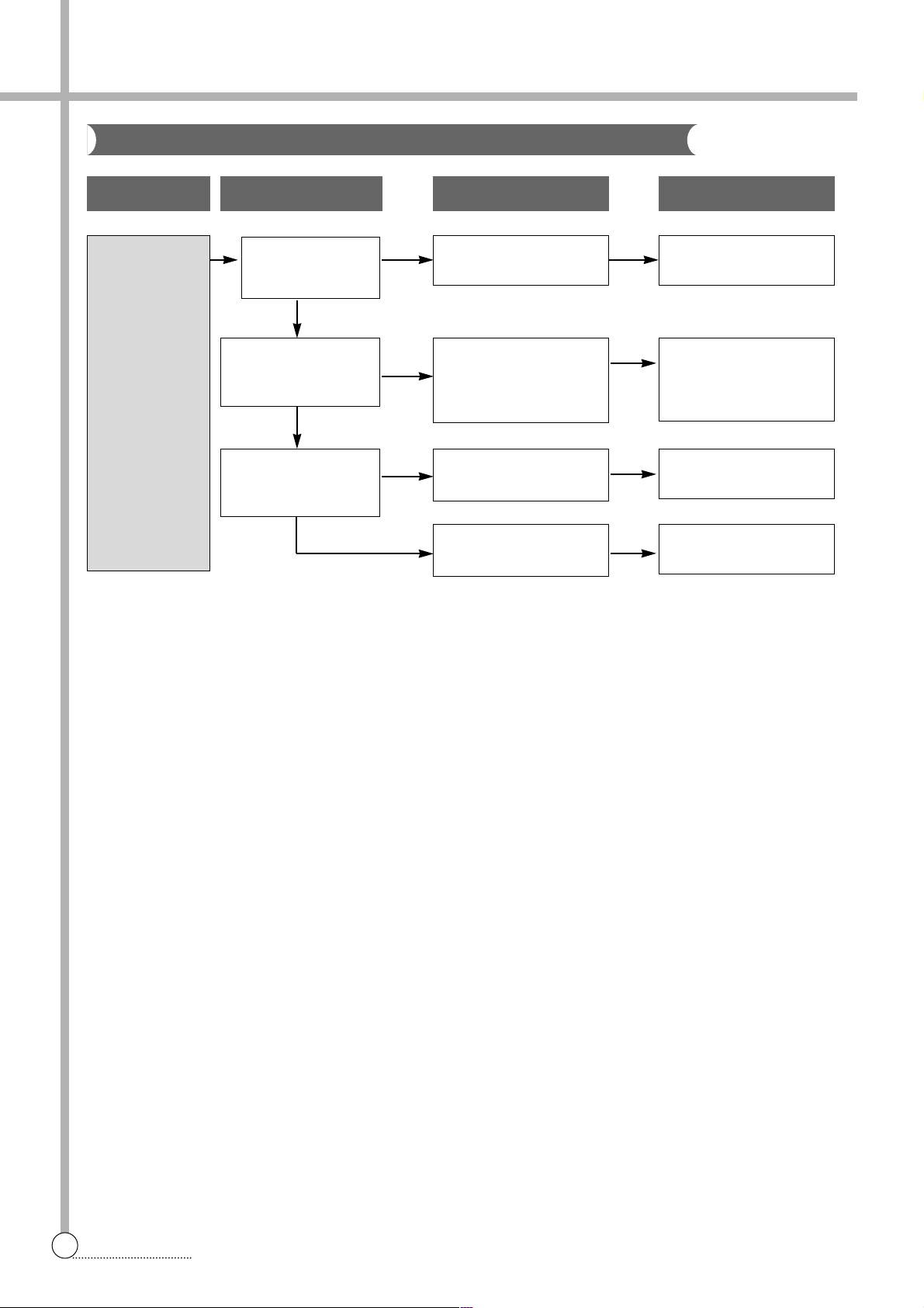
TROUBLE SHOOTING
PROBLEM
THE WASHER
DOES NOT
DRAIN.
CHECK POINT
Do you install the
drain hose properly?
Is the foreign matter
accumulated inside
the pump housing?
Is the output voltage of
the drain pump normal?
CAUSE SOLUTION
Install the drain hose
properly .
Remove the foreign matter from the pump housing
Change the Drain pump
Change the P.C.B ASS’Y.
Improper installation
Malfunction of drainage
by the foreign matter
Drain pump is defective
P.C.B ASS’Y is defective.
YES
NO
NO
NO
YES
YES
Concerning Draining
Page 26
25
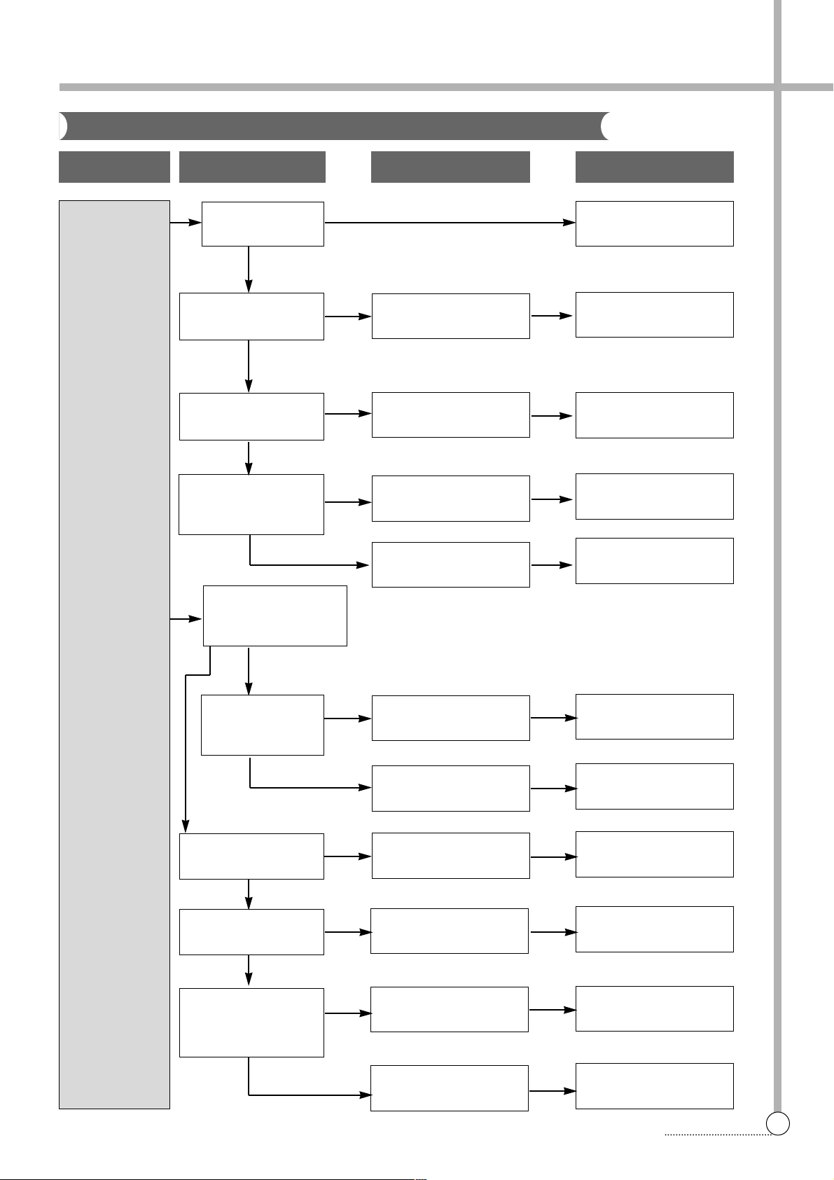
TROUBLE SHOOTING
PROBLEM
THE WASHER
DOES NOT
SPIN.
CHECK POINT
Is the lid open?
Does the door switch
operate normally?
Does the safety switch
operate normally?
Does the pulsator rotate
while the tub does not
rotate?
Is the connector of
P.C.B ASS‘Y connected
properly?
Is the input
voltage of the drain
motor normal?
Is the V-belt worn out?
Is the input voltage of
motor normal?
Is the connection condition of capacitor terminal good?
CAUSE SOLUTION
Close the lid.
Change the door switch.
Change the safety
switch.
Connect the connector
properly .
Change P.C.B ASS’Y.
Change the drain motor.
Change the P.C.B ASS’Y.
Change the V-belt.
Change the motor.
Connect the terminal correctly .
Change the P.C.B ASS’Y.
Door switch is defective.
Safety switch is defective.
Improper connection of
the connector.
P.C.B. ASS’Y is defective.
Drain motor is defective.
P.C.B ASS’Y is defective.
V-belt is defective.
Motor is defective.
Improper connection.
P.C.B ASS’Y is defective.
NO
YES
YES
NO
NO
YES
YES
YES
NO
NO
NO
NO
YES
YES
NO YES
Concerning Spinning
Page 27
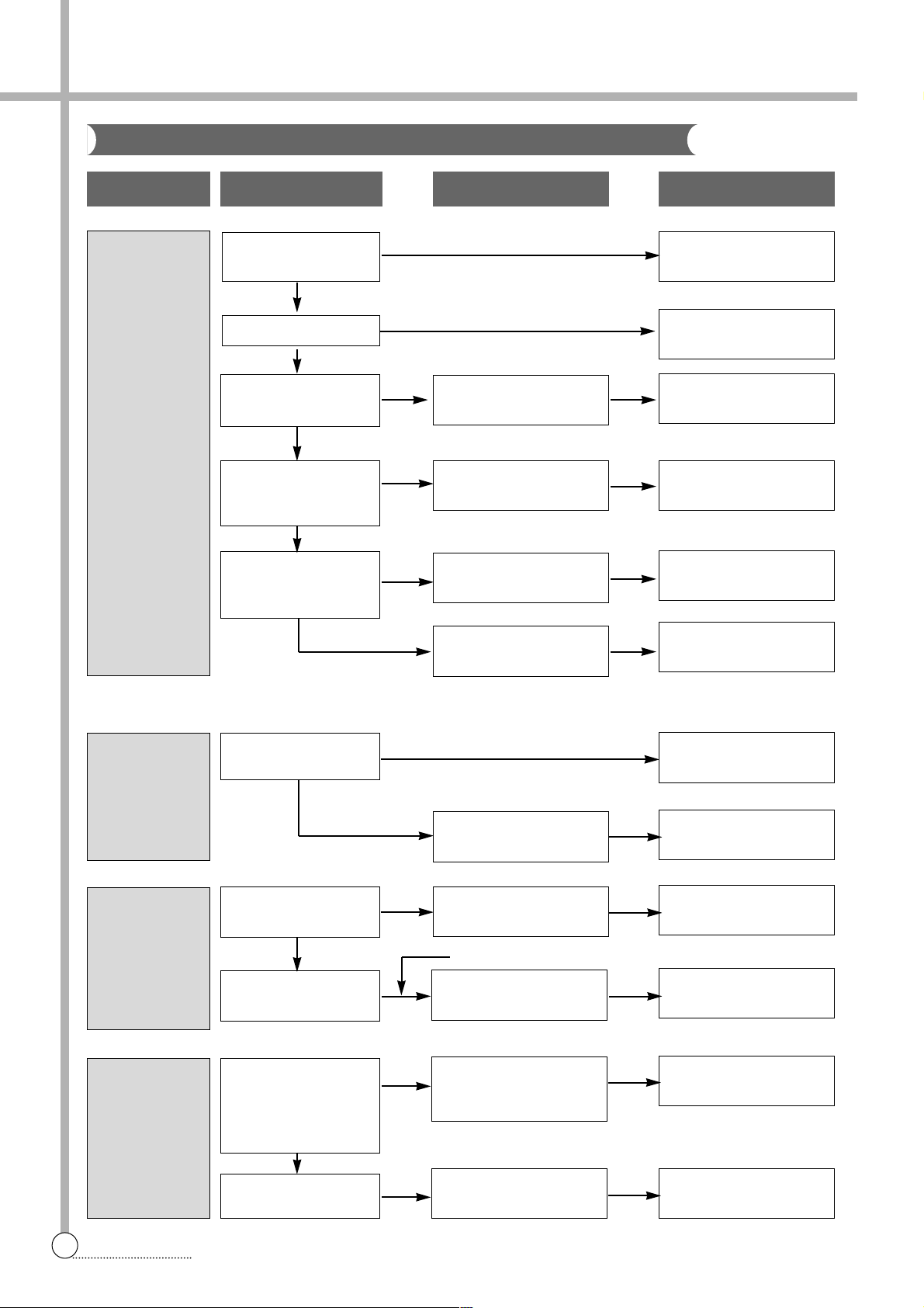
26
TROUBLE SHOOTING
NO
NO
NO
PROBLEM
THE INDICATOR
LAMPS(L.E.D)
DO NOT LIGHT
UP WHEN THE
POWER BUTTON IS
PRESSED.
PROGRESS
LAMPS(LED)
DO NOT LIGHT
UP.
MOTOR
ROT ATES
WHEN
ST AR T/HOLD
BUTTON IS
NOT
PRESSED.
ABNORMAL
NOISE DURING WASH
PROCESS.
CHECK POINT
Is the plug connect-ed
to electric outlet?
Is the condition of
power button good?
Is the connector of the
P.C.B. ASS’Y connected properly?
Is input voltage of the
transformer normal?
Do you press
ST ART/HOLD button?
Does the pressure switch
operate normally?
Check the output voltage
of P.C.B ASS’Y
Is the strange noise generated when the pulsator
rotates in TEST MODE
of P.C.B ASS’Y?
Is the V-belt worn out?
CAUSE SOLUTION
Connect the plug.
Change P.C.B ASS’Y.
Change Fuse
Connect the connector
properly .
Change P.C.BAss’y
Change P.C.B ASS’Y.
Press ST AR T/HOLD button.
Replace P.C.B ASS’Y.
Change the pressure
switch.
Change P.C.B ASS’Y.
Remove the foreign matter.
Change the V-belt.
Power button is defective
Improper connection of
the connector.
Transformer is defective
P.C.B. ASS’Y is defective.
P.C.B ASS’Y is defective.
Pressure switch is defective.
P.C.B ASS’Y is defective
There is foreign matter
between pulsator and
tub.
V-belt is defective.
NO
YES
YES
YES
YES
NO
NO
YES
YES
Abnormal
YES
YES
NO
NO
Is Fuse opended?
Concerning Operation
Page 28
27
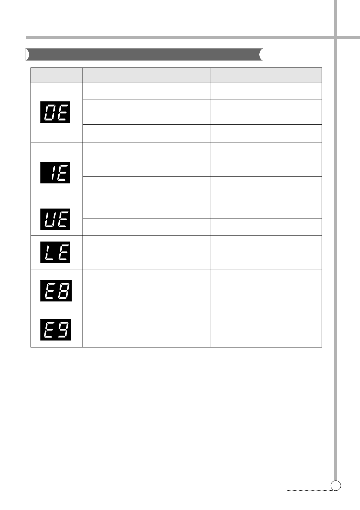
PCB ASS’Y
8. PRESENTATION OF THE P.C.B ASS’Y
MESSAGE CAUSE SOLUTION
Improper installation of drain hose.
The drain hose is blocked up by foreign
matter.
Drain motor is inferior.
The water tap is closed.
The water inlet filter clogged.
It passes over the 60 minutes, yet it doesn’t
come to assigned water level.
Wash loads get uneven during spin.
Poor installation of the unit.
The lid is opened.
The safety switch is inferior.
The load sensing is inferior. After the load
sensing operates about 7 seconds, the
message is displayed during 0.5 second
and water level is always fixed ‘high’.
The water level sensing is inferior.
Install drain hose properly.
Remove foreign matter from drain hose.
Change drain motor.
Open the water tap.
Clean the water inlet filter.
Check whether or not is comes to the
assigned water level.
Re-set wash loads evenly.
Proper installation.
Close the lid.
Change the safety switch.
Change the P.C.B. ASS’Y.
Check the water level sensor and the
contact part of the connector.
Concerning Error Message
Page 29

28
WIRING DIAGRAM
APPENDIX
Wiring Diagram [Pump, Multi Valve]
Page 30
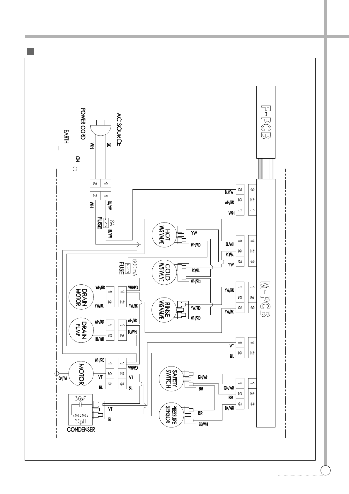
29
WIRING DIAGRAM
Wiring Diagram [Pump, Multi Valve]
Page 31
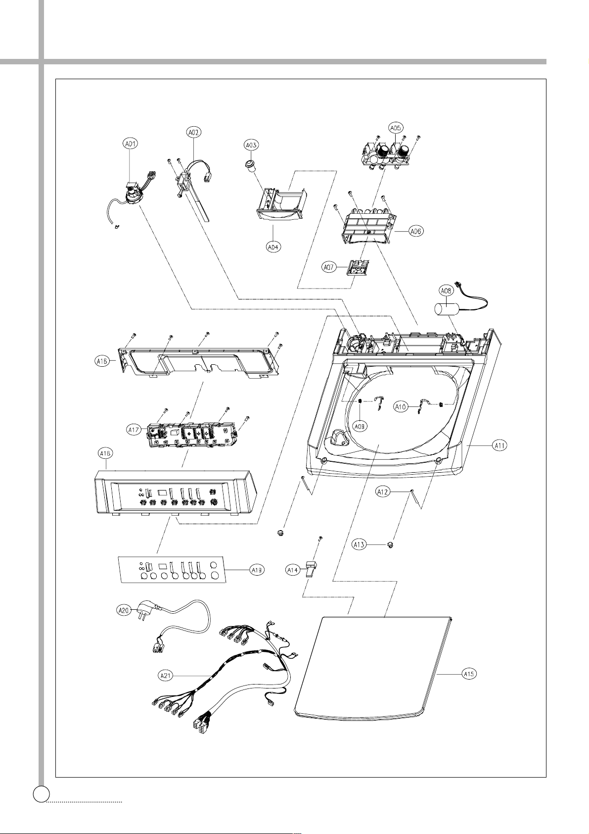
30
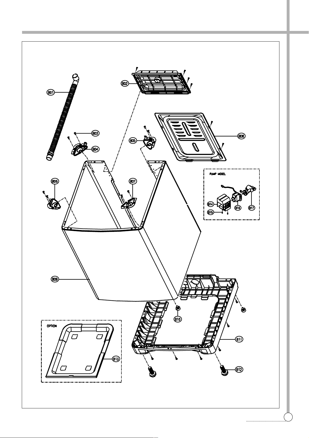
PARTS DIAGRAM
PARTS DIAGRAM
Page 32
31
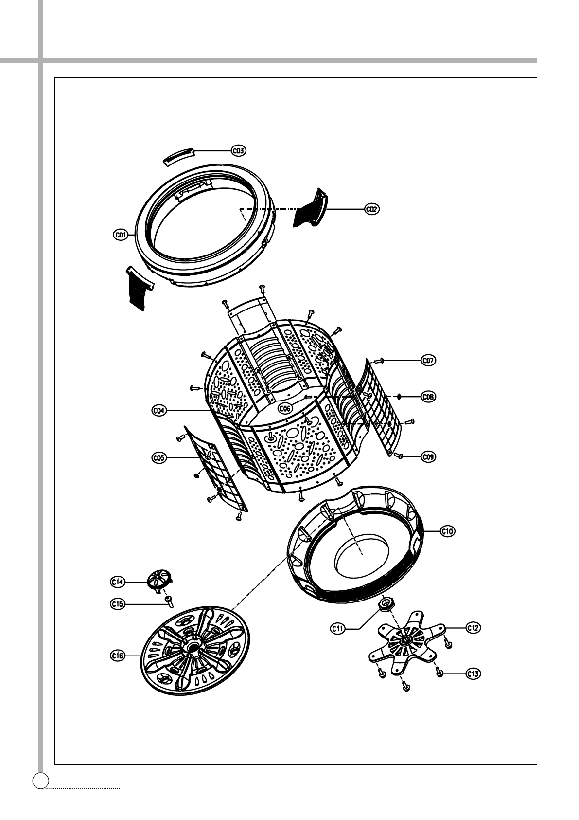
PARTS DIAGRAM
Page 33
32
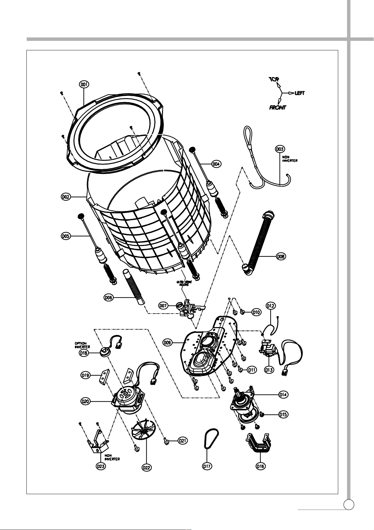
PARTS DIAGRAM
Page 34
33
PARTS DIAGRAM
Page 35
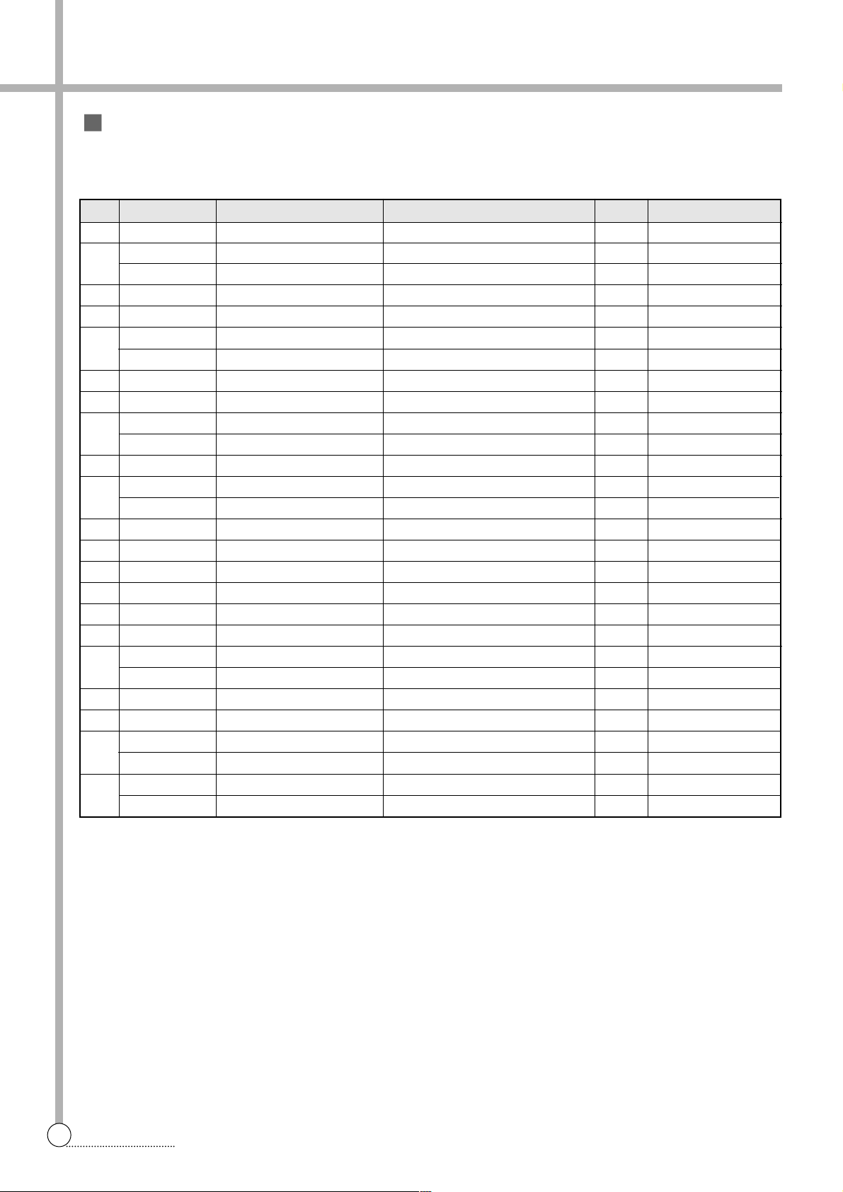
Parts List
✔ Caution
:
In this Service Manual, some parts can be changed for improving, their performance without notice in the
parts list. So, if you need the latest parts information,please refer to PPL(Parts Price List) in Service
Information Center (http://svc.dwe.co.kr).
34
PARTS DIAGRAM
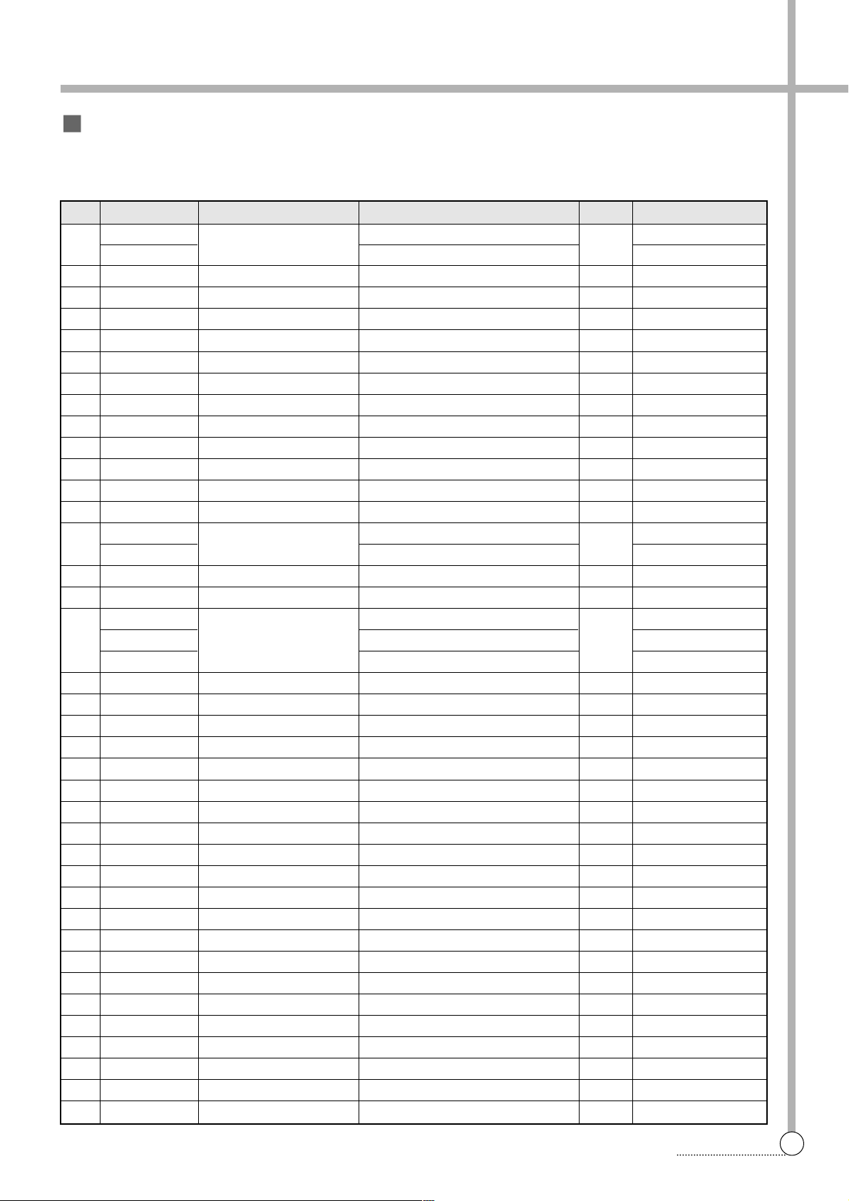
NO. P ARTS CODE PARTS NAME DESCRIPTION Q'TY REMARK
A01 3614802301
SENSOR PRESSURE AS
15µµ,2-PIN,CDN2-D01N,CDL-DC 1
A02
3619044220 SWITCH SAFETY SF-030A15,#187,CU/T9,CU/L11 1 240V/50HZ
3619044180 SWITCH SAFETY SF-030A13,#187,CU/T9,CU/L11 1 127V/60HZ
A03 3610907800 CAP SOFTNER PP 1
A04 3611138100 CASE DETERGENT ABS, DWF-200A 1
A05
3615407920 V ALVE INLET AS
240/50,FLOW-CONTROL,DR-98M-2
1 240V/50HZ
3615407930 V ALVE INLET AS 110-130V 50/60HZ DR-98M-2 1 127V/60HZ
A06 3610430100 BODY DETERGENT ABS, DWF-200A 1
A07 3618102900 NOZZLE DETERGENT PP , DWF-200A 1
A08
361891 1200 UNIT CAPACITOR AS 11.4UF 400VAC,CAN TYPE 1 240V/50HZ
3618912100 UNIT CAP ACITOR AS 36UF 200VAC,CAN TYPE 1 127V/60HZ
A09 3610702200 BUSHING HINGE POM, DWF-200A 1
A10
361A101800 DOOR HINGE R SUS, D=6, DWF-200A 1
361A101900 DOOR HINGE L SUS, D=6, DWF-200A 1
A1 1 3614529800 PLA TE T ABS, DWF-200A 1
A12 7112503011 SCREW TAPPING T1S,TRS,5*30 MFZN 2
A13 3611561400 CUSHION DOOR NBR, DWF-200A 2
A14 3613702600 LEVER SAFETY S/W ABS, DWF-200A 1
A15 361A101700 DOOR SECC 1.0T, DWF-200A 1
A16 3611424100 COVER PANEL B ABS, DWF-200A 1
A17
PRPSSW3N01 PCB AS DWF-200AMP 1 240V/50HZ
PRPSSW3N02 PCB AS DWF-200ASP 1 127V/60HZ
A18 3614280510 PANEL B ABS, DWF-200A 1
A19 3611629400 DECORATOR FILM PC FILM 0.188T,DWF-200A 1
A20
361 1337210 CORD POWER AS N LFC-3R 3X0.75 1.9M GY 1 240V/50HZ
361 1332810 CORD POWER AS A VCTFK 2X0.75 1.9M BK 1 127V/60HZ
A21
3612792700 HARNESS AS
220V,PUMP ,H&C&R,DWF-200AMP
1 240V/50HZ
3612792710 HARNESS AS
1 10V,PUMP,H&C&R,DWF-200ASP
1 127V/60HZ
Page 36
Parts List
✔ Caution
:
In this Service Manual, some parts can be changed for improving, their performance without notice in the
parts list. So, if you need the latest parts information,please refer to PPL(Parts Price List) in Service
Information Center (http://svc.dwe.co.kr).
35
PARTS DIAGRAM
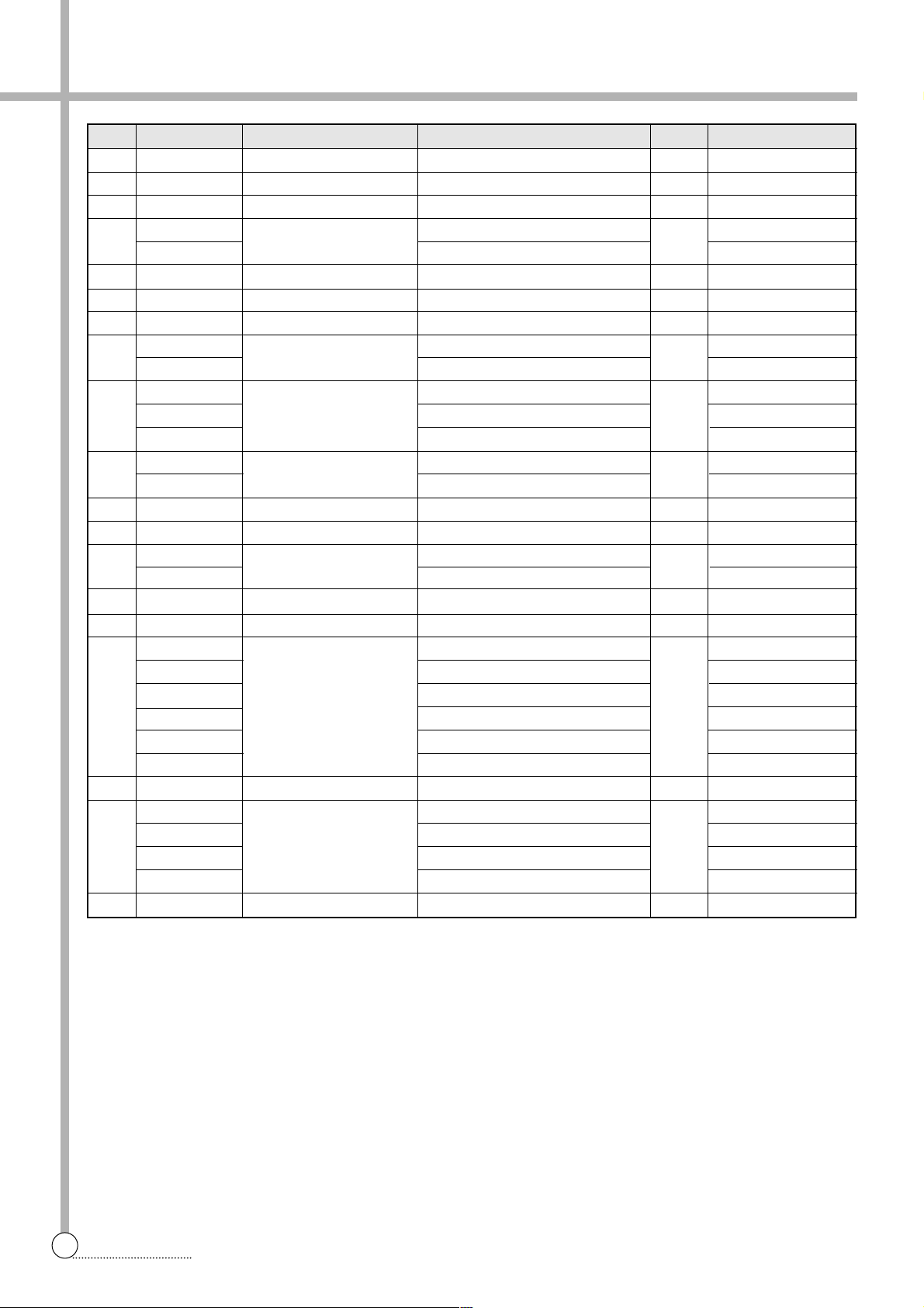
NO. PARTS CODE PARTS NAME DESCRIPTION Q'TY REMARK
B01 3613213560 HOSE DRAIN O 1089 CTE 950MM 1 NON PUMP
3613218800 HOSE DRAIN O AS LD-PE/EV A L=1600 PUMP PUMP
B02 3614514600 PLATE UPPER PP 1
B03 7112501411 SCREW TAPPING T1 TRS 5*14 MFZN 8
B04 3615302210 SUPPORTER TUB BL SPG 1.4T 1
B05 3615302310 SUPPORTER TUB BR SPG 1.4T 1
B06 3615302410 SUPPORTER TUB FL SPG 1.4T 1
B07 3615302510 SUPPORTER TUB FR SPG 1.4T 1
B08 3611413600 COVER BACK SPG 0.4T 1
B09 3610808011 CABINET PAINTING(0.6) 1
B10 3617702300 LEG FIX THERMAL PLASTIC ELASTOMER 2
B1 1 3610310200 BASE U PP 1
B12 3617702010 LEG ADJUST PP 2
B13 3611402711 COVER UNDER PP 1
B14 3611405320 COVER PUMP PP(B360F) 1
361 1405301 UL/CSZ(466FWU, HFH-400)
B15 7112501611 SCREW TAPPING T1 TRS 5*16 MFZN 2
B16 3618957200 MOTOR SHADED POLE 230-240V/50HZ L=1350 VSF 1
3618957230 220V/50HZ L=1350 VSF
3618957260 220V/60HZ L=1350 VSF
3618957300 110-127V/60HZ L=1350 VSF
B17 3611901530 FILTER AS DWF-5591 DPNF E-TYPE 1
C01 3616105400 BALANCER AS 100'S, HIDDEN 1
C02 361 1904700 FILTER AS 100'S LINT FIL TER AS 2
C03 3612202900 FRAME F ALL PP 1
C04 3618815300 TUB SUS 1
C05 3612507210 GUIDE FILTER AS HIDDEN FILTER(SUS 0.6T) 3
C06 3616008600 SPECIAL BOLT SUS 6 FOR GUIDE FILTER
C07 3616003700 SPECIAL SCREW SUS 5.5*16 12 FOR BALANCER AS
C08 3616008700 SPECIAL NUT SUS 6 FOR GUIDE FILTER
C09 3616003700 SPECIAL SCREW SUS 5.5*16 12 FOR TUB U
C10 3618815201 TUB U FRPP-M/B 1
C1 1 4507D83080 SPECIAL NUT SUS 304 1
C12 3617201200 FLANGE TUB 10KG 3-FOOT 1
C13 3616007000 SPECIAL SCREW SCM 24H, 6.5*24 3
C14 361091 1200 CAP PULSATOR PP 1
C15 3616003720 SPECIAL SCREW SUS 6*26.5 1
C16 3619705510 PULSATOR AS 100M 1
D01 361 1417700 COVER TUB O PP, 100M 1
D02 3618807100 TUB O 1098 1 NON PUMP
D03 3613200781 HOSE AS L=1350MM 1 OPTION
D04 3619805400 SUSPENSION AS(A) 100C'S ROD=592 SPR=102 2
Page 37
NO. PARTS CODE PARTS NAME DESCRIPTION Q'TY REMARK
D05 3619805500 SUSPENSION AS 100C'S ROD=592 SPR=112 2
D06 3613208901 HOSE OVERFLOW PELD, L=280MM 1 NON PUMP
D07 3615408400 VALVE DRAIN AS 1098'S, VE TYPE 1 NON PUMP
D08 3613218500 HOSE DRAIN I AS LDPE+EVA, L=219.5 1 NON PUMP
3613217700 HOSE DRAIN I PELD, L=219.5 PUMP
D09 3610387400 BASE SECEN 2.0T 1
D10 3616006900 SPECIAL SCREW SCM 24H, 6.5*18 4
D1 1 3616007000 SPECIAL SCREW SCM 24H, 6.5*24 12
D12 3612712200 INNER EARTH WIRE GN VSF(30/0.18) 1
3612713150 HARNESS EARTH WIRE VSF YW/GN L1=620 L2=200
D13 3966010430 MOTOR SYNCHRONOUS 220-240V/50, 60HZ, 23, 1806 1 PUMP/NON PUMP
3966320810 110-127V/50, 60HZ, 23, 1806 PUMP/NON PUMP
3618957640 110V/60HZ, 23, 1806 240MTC
D14 3617307610 GEAR MECHANISM GM-1300-KS6P0 1
3617308310 GM-2000-KS6P2 240MTC
D15 734180151 1 BOLT HEX 6B-1 8*15 MFZN 4
D16 3618301300 PROTECTOR GEAR SBHG 1.6T 1
D17 3616590220 BELT V M20.5, AGING 1 60HZ
3616590230 M21, AGING 50HZ
D18 3614800710 SENSOR HALL AS DWF-100MV, 5.4 1 INVERTER
D19 361 1502700 CUSHION DOWN POM(8MM) 2
D20 3964221231 MOTOR CONDENSER 110-127V 60HZ, W1S50CA011 1
3964510430 220-240V 50HZ, W1D50VA011
3964321261 220V 60HZ, W1D50UA014
3964821320 120-127V/60HZ, W1D50JA001
3964221020 110V 60HZ, WM244EA011 240MTC
3618956310 W1N44UA302 3-BRACKET INVERTER
D21 7650802528 BOLT HEX 6B-1 8*25 PW(3*28) MFZN 2
D22 3618432000 PULLEY MOTOR AS M-TYPE DS=10 DP=48.5 60HZ 1
3618431900 M-TYPE DS=10 DP=53 50HZ
3618403510 ADC-12 DS=12 DP=52.5 60HZ 240MTC
3618431300 ADC-12 DP=60.5 50HZ INVERTER
D23 3610402921 BODY BUBBLE AS 100M, 200M, HOSE=1580MM 1
36
PARTS DIAGRAM
Page 38
37
PARTS DIAGRAM
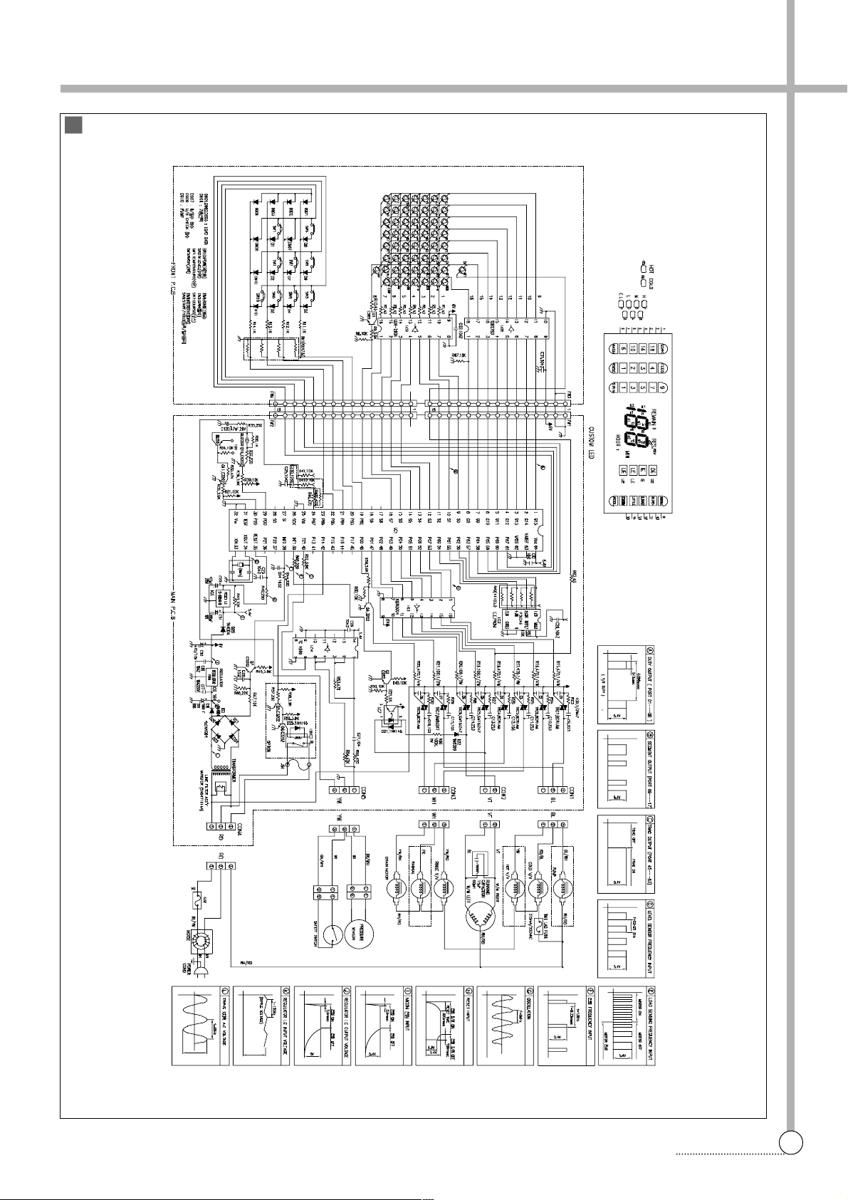
Circuit Diagram [DWF-200A]
Page 39

S/M No. : WF200A01
DAEWOO ELECTRONICS CORP.
686, AHYEON-DONG MAPO-GU SEOUL, KOREA
C.P.O. BOX 8003 SEOUL, KOREA
TELEX: DWELEC K28177-8
CABLE: “DAEWOOELEC”
PRINTED DATE: Jul. 2003
 Loading...