

Page 1

1
Please observe the following instructions.
1. Operate the Selector Switch to run or stop the unit.
- Do not use Main Power Switch or Auxiliary Power Switch to operate unit.
2. Do not stick anything into the air outlet or inlet.
- It is dangerous and it can cause injury or damage.
3. Avoid exposing your body directly to a continuous cool air - flow for long periods.
- It is not good for your health.
4. Do not pour water on the unit to clean it.
- It is dangerous and it can cause injury or damage.
Never use solvents or harsh chemicals when cleaning the unit.
When the air inlet grill and cabinet are dirty, wipe with luke - warm water (below 104°F or 40°C)
5. Avoid placing any obstacles near the inlet or outlet.
- If the inlet or outlet is blocked with any obstacle, it may cause damage to the unit.
6. Do not run or stop the unit frequently.
- If you run or stop the unit more then 4-5 times an hour, it can cause damage to the unit.
7. Wait at least 3 minutes before restarting the unit or in the case of power failure.
- If you turn on the unit within 3 minutes after power off, this can cause damage to the unit.
8. If the air conditioner is operated without an air filter, dust is not removed from the air, and resultant
accumulation in the unit may lead to a failure.
- Do not forget to install the air filter.
9. The air filter should be cleaned at least once every two weeks.
10. When the unit is cleaned, set the Selector Switch at off position.
- And then unplug the power plug.
11. Never store gasoline or other flammable liquid near the air conditioner.
- It is very dangerous.
12. Do not force the controls on the front panel too much.
- It can cause damage the controls and the unit.
13. Set a comfortable temperature.
- Very low temperature setting considerably increase power consumption.
14. Be careful to keep room temperature comfortable.
- Avoid continuous direct air flow on you or a sick person while sleeping.
15. Do not remove the plug by pulling the power cord.
- Damage to the cord and may cause shock hazard.
PRECAUTIONS FOR PROPER USE OF AIR CONDITIONER
Page 2
2
1. GENERAL SPECIFICATIONS...............................................................................2
2. INSTALLATION INSTRUCTIONS.......................................................................3~8
• WINDOW REQUIREMENTS
• BASIC T OOLS NEEDED
• SAFETY INSTRUCTIONS
• BEFORE INSTALLA TION
• STEP1-PREPARE COMPONENTS FOR INSTALLA TION
• STEP2-PREPARE WINDOW FOR INSTALLATION
• STEP3-PREPARATION OF CHASSIS
• STEP4-PLACING CHASSIS
• STEP5-SECURE WINDOW SHUTTER
• STEP6-RECHECK INSTALLA TION
• STEP7-INSTALL UNIT AND ASSEMBLE FRONT GRILLE
• STEP8-RECHECK THE ENTIRE INSTALLA TION
3. NAMES OF MAJOR COMPONENTS .....................................................................9
4. OPERATION INSTRUCTIONS .......................................................................10~15
• DISPLAY
• REMOTE CONTROL
• HOW TO INSERT BATTERIES
5. GENERAL INFORMATION.................................................................................16
• CHANGING AIR FLOW DIRECTION
• AIR FLOW AROUND UNIT
• DRAIN HOLE AND WATER DRIPPING OUTSIDE
6. CARE AND MAINTENANCE ..............................................................................17
• AIR FILTER
• CLEANING THE AIR CONDITIONER
7. ELECTRICAL REQUIREMENTS .........................................................................18
• ELECTRICAL GROUNDING INSTRUCTIONS.
• USE OF EXTENSION CORDS
8. BEFORE CALLING FOR SERVICE......................................................................19
TABLE OF CONTENTS
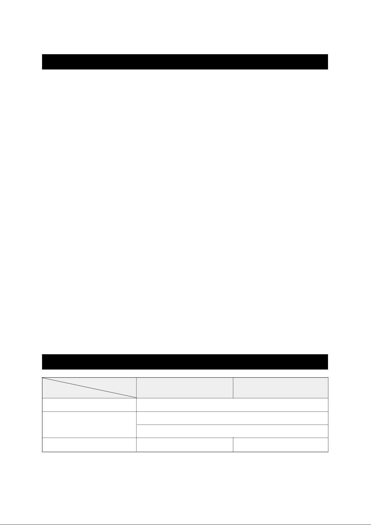
GENERAL SPECIFICATIONS
MODEL
ITEM
POWER SOURCE
DIMENSIONS
WEIGHT
DWC-064R
62.8 Ibs (28.5 Kg)-Approx.
DWC-084R
65 Ibs (29.5 Kg)-Approx.
AC 115V, 60Hz, SINGLE PHASE
18.9(W) x 14.6(H) x 19.5(D) inch
480(W) x 369(H) x 497(D) mm
Page 3
3
INSTRUCCIONES DE INSTALACION
• REQUERIMIENTOS PARA UNA INSTALACION CORRECTA
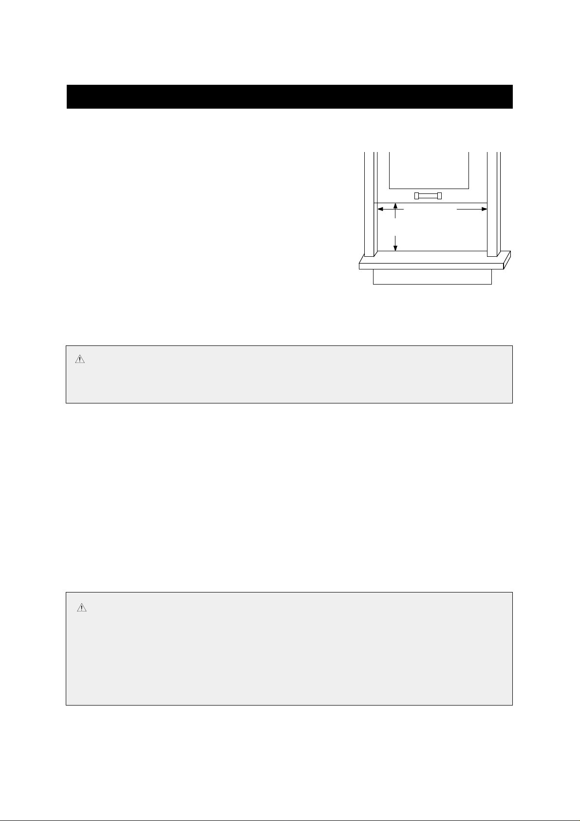
Las instrucciones son para la instalación de un equipo estándar
colgado de doble ventana 23.2 pulgadas (590mm) a 36.2 pulgadas
(920mm). Las bandas inferior y superior se deben abrir lo
suficiente para permitir una entrada vertical de 14.9 en (379mm)
desde la parte inferior de la banda hasta la corniza de la ventana.
Seleccione una parte centrada en el cuarto que sea la ultima
donde la luz del sol de directamente. No debe haber ninguna
obstrucción por donde fluye el aire por dentro (cortinas) por fuera
(matorrales, muros o cercas).
Lea la instalación manual, antes de comenzar a instalar el equipo.
Asegúrese de tener el material y las herramientas necesarias para
el trabajo.
Estudie las ilustraciones contenidas en las instrucciones para familiarizarse Con el proceso y los detalles de la
instalación.
Lea el manual de Uso y Cuidado para familiarizarse con la operación en el cuarto del aire condicionado.
After installing the unit, re-read these instructions to make sure you have completed each step and all parts are
fastened in place for a secure installation.
For best results, perform the installation procedure in the order given. Doing so will minimize the time required
to install the unit.
• BASIC T OOLS NEEDED
• SAFETY INSTRUCTIONS
IMPORTANTE :
Es importante , que para su seguridad personal y evitar posibles daños para su hogar, que observe
cuidadosamente las instrucciones de seguridad que se dan en el instructivo.
• Standard screwdriver
• Carpenter’s level
• Electric drill
• Phillips screwdriver
• 1/4” hex driver
• 1/8” drill bit
• Sharp knife
• Tape measure
22" TO 36"
14 1/2" MIN
CAUTION
• The air conditioner shall be installed in accordance with the national wiring regulation.
1. Install an exclusive main power switch (main circuit breaker) or GFI (Ground Fault Interrupted)
switch.
2. Be sure to use grounded power source.
3. Power source for DWC-064R, DWC-084R is 115V.
4. Consumer must pay charges for wiring and installation.
23.2" To 36.2"
14.9" MIN
Page 4

4
• SAFETY INSTRUCTIONS (CONTINUED)
The receptacle should be an individual branch circuit used only for this air conditioner. Be sure the electrical
service is adequate for the model air conditioner you have chosen. The complete electrical rating of your air
conditioner is stated on the name plate located at the unit’s side. Be sure the plug receptacle is close enough
for the power cord to reach it.
Your air conditioner must be plugged into a properly grounded and polarzied three prong receptacle. Do not
use an adapter plug. If the wall receptacle you intend to use will not accept a three-prong plug, or if you are not
sure the outlet is adequately grounded or protected by a fuse or circuit breaker, have a qualified electrician
install the proper oulet according to the National Electric Code and applicable local code.
• BEFORE INSTALLATION
Test Run Unit : Plug unit into proper power supply outlet.
Refer to operating instructions in this manual for comfortable living. Check all controls for correct
operation, then unplug unit.
Determine Correct Mounting procedure-Refer to Window Installation or Through the Wall Installation.
WARNING :
An extension cord should not be used with your air conditioner!
To minimize shock and fire hazards, proper grounding is important. For your safety and
protection,this air conditioner is equipped with a special three-prong grounding plug on the service cord.
WARNING :
Do not, under any circumstances, cut or remove the grounding prong on the plug. To do so will create a shock
hazard.
WARNING :
• Moving parts can cause personal injury. Be careful when test-running unit. Do not operate
unit with front grille removed .
• Be sure to use an exclusive power source.
• Contact service man for replacement of power cord.
Page 5
5
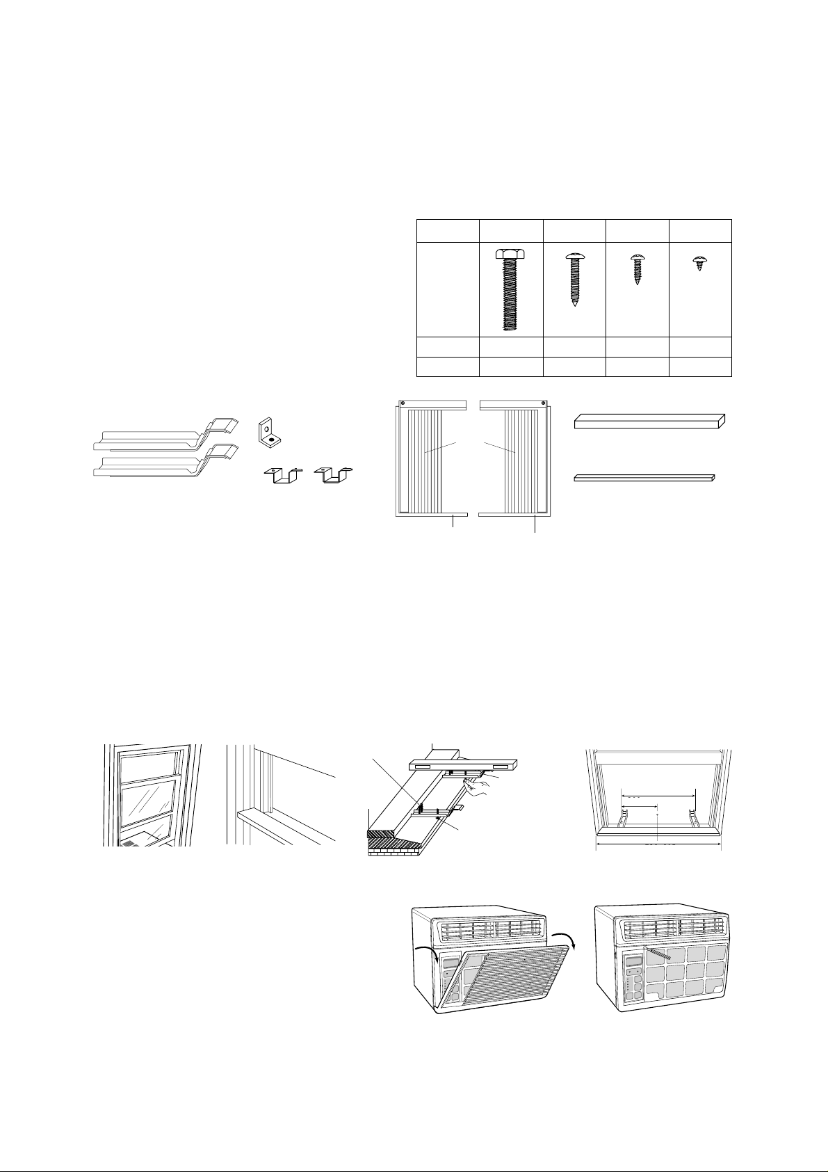
• Step 1 - Prepare Components For Installation
Parts for installation are as follows;
• Sill Bracket (2 pieces)
• Window Kit Left side (Frame ‘L+Shutter) - (1 piece)
• Window Kit Right side (Frame ‘R+Shutter) - (1 piece)
• Sash Bracket (1 piece)
• Frame Guide Lower - (2 pieces)
• Levelling Screw (Machine M8x45) - (2 pieces)
• 11/4inch Screw (M5x30) - (4 pieces)
• 5/8 inch Screw - (M4x16) - (8 pieces)
• 1/4 inch Screw (M4x6) - (8 pieces)
• Window Seal A, B (2 pieces)
• Step 2 - Prepare Window For Installation
1. Inspect window track, sash and sill to be sure they are strong enough to hold an air conditioner.
2. Measure width between window frame to be sure instant mount will fit in the window. Instant mount models are
designed for Windows 23.2 inch (590mm) to 36.2 inch (920mm) wide.
3. Mark the center of Window sill with pencil.
4. Insert Screws (Type A) into the sill bracket.
5. Attach Sill bracket to window sill using two Screws (Type B) by each bracket. The outside edge of window bracket
should be 9.4 inch (240mm) from center line.
6. Adjust Screw (Type A) so that Sill Bracket have a slight tilt by using carpenter's level meter.
• Step 3 - Preparation of Chassis
1. Open the inlet grille downward by pulling out the
both side of the inlet grille.
2. Remove screw which fasten Front Grille with screw
drivers.
300mm
600mm
720~915mm
Screw Type B
SILL
Screw Type A
SILL BRACKET
Window
Shutter
(2 pieces)
Window Seal A (1 piece)
Window Seal B (1 piece)
Sill Bracket (2 pieces)
Window kit Frame
Left side (1 piece)
Window kit Frame
Right side (1 piece)
Sash Bracket
(1 piece)
Frame Guide Lower
(2 pieces)
SHAPE
SPEC
Q'TY
Type A
M8 x 45
2
Type B
M5 x 30
4
Type C
M4 x 16
8
Type D
M4 x 6
8
• SCREW TYPE
480mm
590~920mm
SASH
240mm
Page 6
6
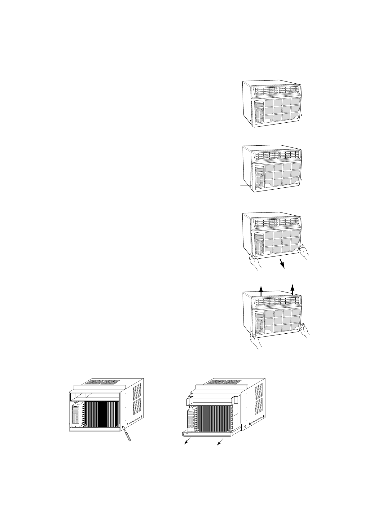
3. Disassemble Front Grille from Chassis.
– Front Grille and chassis are fixed with snap-fit.
1) Release right-lower snap-fit.
– Push the right lower side of chassis to the left, with pushing left side
of Front Grille to the right until the snap-fit is released.
2) Release left-lower snap-fit.
– Push the left-lower side of chassis to the right, with pushing right
side of Front Grille to the right until the snap-fit is released.
3) Pull lower side of the Front Grille until it is separated from the
chassis.
4) Push base side of the Front Grille to upper side until it is separated
from the chassis.
4. After front grille is removed, remove two screws located in both side of chassis and pull out the unit from chassis.
Push
Push
Push
Push
Page 7
7
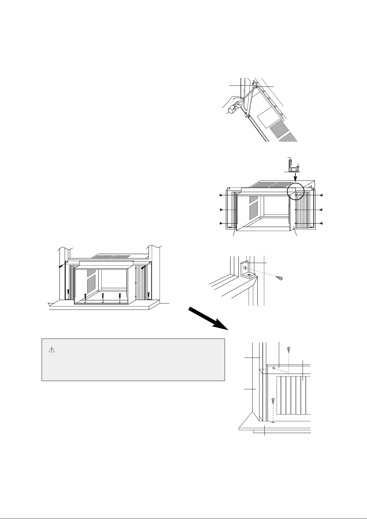
• Step 4 - Placing Chassis
1. Insert narrow side of ‘Frame Guide Lower’ to rectangle holes
located in bottom of chassis, and fasten it with Screw (Type D).
2. Insert Window Kit Frames to Top Guide and Lower Guide.
3. Fasten Shutter to side holes of Chassis with six Screws (Type D).
4. Place the chassis on the window sill and align it with Sill Bracket
and sill with Lower Frame Guide and locate window sash to Top
Frame Guide. (check the end of chassis for about 1/2 inches
(12mm) distance below the level.)
5. Attach the Window seal B to Frame Guide Top.
6. Fasten Front Chassis Bracket to sill with three Screws
(Type C).
7. Fasten Sash Bracket with Screw (Type C) to top of
indoor window sash or directly into side of window sash
or directly into side of window frame. This will prevent
raising of the window from the outside. If you have a hard
wood or metal window frame, a 1/8 inch pilot hole may
be needed in order to drive the screws.
8. Attach the Window Seal A to window (see the picture
shown in step 8, page 8)
• Step 5 - Secure Window Shutter
To provide a proper seal, pull each expandable side Window Shutter
out and up until it is tight against the window frame. Using the hole in
the top and bottom of each Window Kit Frame as a guide, secure
Window Kit Frame in window sash and on the window sill.
Screw (Type E, both side)
FRAME
Guide Lower
Frame Guide Top
Window Seal B
Screw (Type C)
Screw (Type D)
Screw
(Type C)
SASH BRACKET
CAUTION Do not drill into window sash until window has
been inspected to make sure drilling or screw will
not damage any locking or lifting mechanism
located in the frame.
Screw (Type D, both side)
WINDOW
SASH
WINDOW
FRAME
INNER WINDOW SILL
WINDOW
KIT FRAME
Screw
(Type C)
Screw (Type C)
WINDOW
SHUTTER
Page 8
8
• Step 6 - Rechec k Installation
To be sure you have correctly installed your Room Air Conditioner, review the steps and make sure all of the
parts are securely fastened in the window as the instructions show. A tight seal is essential.
Read through the Use & Care manual to become familiar with the operation of your room air conditioner.
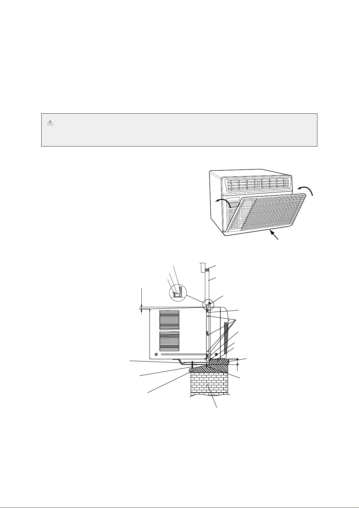
• Step 7 - Install Unit and assemble Fr ont Grille
1. Push the unit into the installed Chassis.
2. Fasten Base Pan and Chassis with screws to side holes.
3. Assemble Front Grille into Chassis holes.
– Snap Front Grille’s hook to each Chassis holes.
4. Fasten Front Grille with screws.
5. Insert Filter into the Front Grille.
6. Attach the inlet grill to the front grille.
• Step 8 - Rechec k the entire installation
WALL
Screw (Type B, 2x2=4 pieces)
SILL
Screw (Type C, 3 pieces)
Screw (Type C, 2x1=2 pieces)
GUIDE LOWER
WINDOW KIT 'R & 'L
Screw (Type D, 2x4=8 pieces)
Screw (Type C, 2 pieces)
WINDOW SEAL A
WINDOW SASH
SILL BRACKET(2 pieces)
OUTER WINDOW SILL
Leveling Screw (Type A, 2x1= 2 pieces)
TOP GUIDE
WINDOW KIT FRAME
WINDOW SEAL B
38mm
0.28"~0.39"(7~10mm)
CAUTION Do not lift window sash without holding the unit. The window sash helps keep the unit in the
window. Exercise caution when opening the window. Failure to do so many result in
personal injury and/or property damage.
Page 9
9
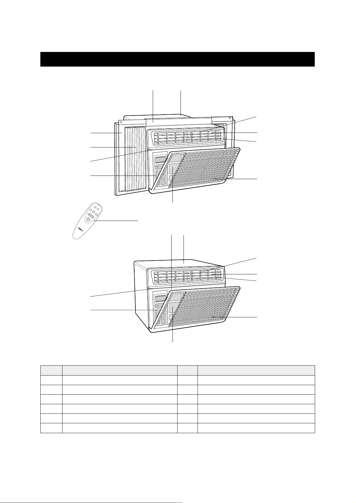
NO PART NAME
1 CABINET
2 BLADE VERTICAL
3 BLADE HORIZENTAL
4 KNOB BLADE
5 GRILLE FRONT
6 INLET GRILLE
NO PART NAME
7 AIR FILTER
8 PANEL CONTROL
9 FRAME GUIDE TOP
10 FRAME WINDOW KIT
11 SHUTTER WINDOW
12 REMOTE CONTROLLER
NAMES OF MAJOR COMPONENTS
9
2
4
0
q
8
7
7
1
7 1
5
5
6
2
4
8
3
3
6
w
Page 10
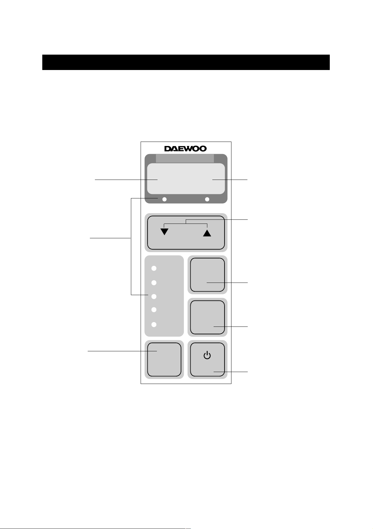
TEMP./TIMER DISPLAY
• It displays the temperature
and the timer.
MODE DISPLAY
• It displays the
operating mode.
REMOTE SIGNAL
RECEIVER
TEMPERATURE SET
• It is the button to set the
desired room temperature.
The temperature can be set
within a range from 16°C
(60°F) to 32°C (90°F) by
1°C (1°F)
POWER ON/OFF SWITCH
• To turn the unit ON, push
this button.
To turn the unit OFF, push
this button again.
MODE SELECT
• Everytime you push this
button, It is selected as
follow. (COOLING→TURBO
→ FAN→COOLING)
FAN SPEED
• Everytime you push this
button, It is selected as
follow. (High→Low→High)
ENERGY SAVE
• Whenever you push this
button, the cumulative power
consumption is decreased.
10
• DISPLAY
OPERATION INSTRUCTIONS
Room Air-conditioner
ROOM TEMP DESIRED TEMP
TEMP
MODE
FAN
SPEED
POWER
ENERGY
SA VE
FAN
TURBO
COOLING
TIMER
ENERGY
SAVE
Page 11
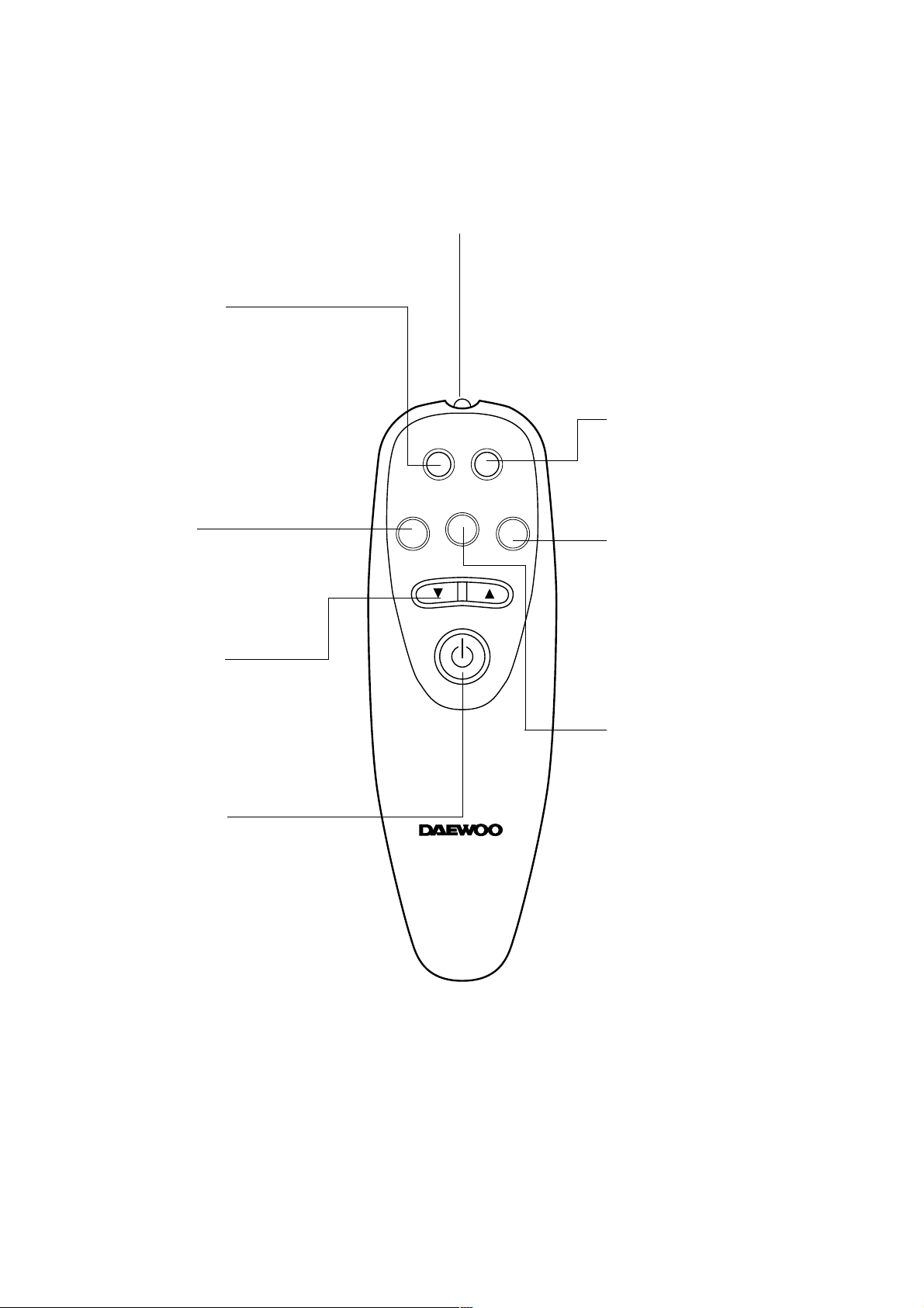
• REMOTE CONTROL
REMOTE SIGNAL TRANSMITTER
TIMER/CANCEL
• Everytime you push this button,
timer is set as follow.
(1Hr→2Hr→3Hr→4Hr→5Hr→6Hr
→8Hr→10Hr→12Hr→16Hr→20Hr
→24Hr→CANCEL).
After the unit is timed, if this
button is pushed, timer is
canceled.
SLEEP
• SLEEP mode is selected as
follow. (L1→L2→Cancel)
MODE
• Everytime you push this
button, it is selected as
follow.
(COOLING→TURBO→FAN
→COOLING)
ENERGY SAVE
• Whenever you push this
button, the cumulative power
consumption is decreased.
TEMPERATURE
• It is the button to set the room in
the desired room temp.
The temp. can be set within a
range from 16°C (60°F) to 32°C
(90°F) by 1°C (1°F)
POWER ON/OFF
• To turn the unit ON, push this
button. To turn the unit OFF,
push this button, again.
FAN SPEED
• Everytime you push this button,
it is selected as follow.
(High→Low→High)
TIMER/
CANCEL
FAN SPEED
TEMP
SLEEP
MODE
ENERGY
SAVE
11
Page 12
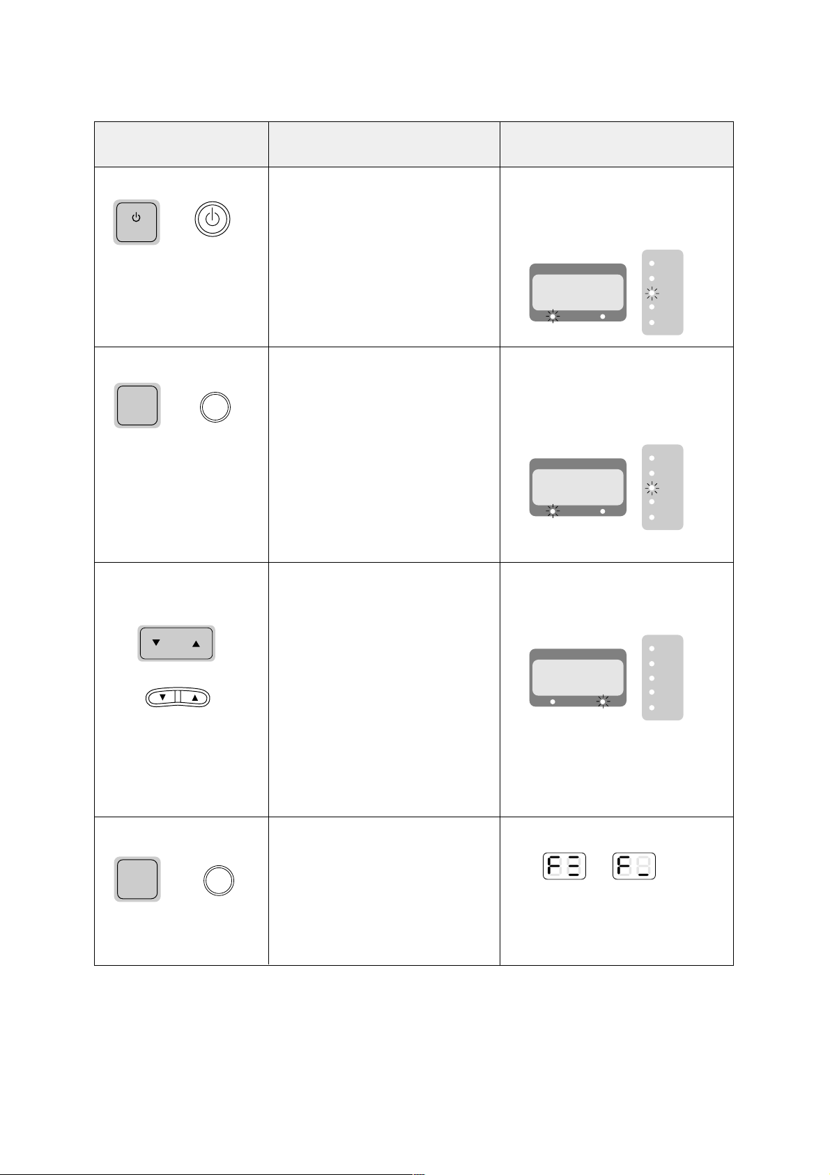
FUNCTION
POWER ON
Push POWER button
COOLING MODE
Push the ‘MODE’ button until
‘COOLING’ lamp lights.
Change desired room
temperature
Push the ‘TEMP▲▼’ button.
Change ‘FAN SPEED’
Push the ‘FAN SPEED’
button.
OPERATION
1. The unit starts working.
(It is delayed 3 minutes after main
power source is supplied.)
2. Default mode is ‘COOLING’ mode.
3. Default desired room temperature is
‘26°C’ (79°F).
And fan speed is ‘HIGH’.
1. Operating modes are changed as
follows by pushing “MODE” button.
(COOLING→TURBO→FAN→
COOLING)
2. The compressor and fan work.
3. In this mode you can change fan
speed and desired temperature at
any time.
4. SLEEP mode and ON/OFF TIMER
can be selected.
(By remocon button only)
1. The desired room temperature is
changed within a range from 16°C
(60°F) to 32°C (90°F) by 1°C (°F)
1. FAN SPEED is changed as follows
by pushing “FAN SPEED” button.
(HIGH→LOW→HIGH)
DISPLAY
1. Current room temperature is
displayed.
2. ‘COOLING’ lamp lights.
3. ‘ROOM TEMP’ lamp lights.
1. Current room temperature is
displayed.
2. ‘COOLING’ lamp lights.
3. ‘ROOM TEMP’ lamp lights.
1. It display desired room temperature
when ‘TEMP’ button is pushed.
2. ‘DESIRED TEMP’ lamp lights.
3. After a few seconds, display is
changed to current room
temperature and ‘ROOM TEMP’
lamp lights.
1. It displays as follows.
2. After a few seconds, display is
changed to current room
temperature.
ROOM TEMP DESIRED TEMP
FAN
TURBO
COOLING
TIMER
ENERGY
SAVE
HIGH
LOW
POWER
MODE
TEMP
MODE
TEMP
FAN
SPEED
FAN SPEED
or
or
or
or
ROOM TEMP DESIRED TEMP
FAN
TURBO
COOLING
TIMER
ENERGY
SAVE
ROOM TEMP DESIRED TEMP
FAN
TURBO
COOLING
TIMER
ENERGY
SAVE
12
Page 13
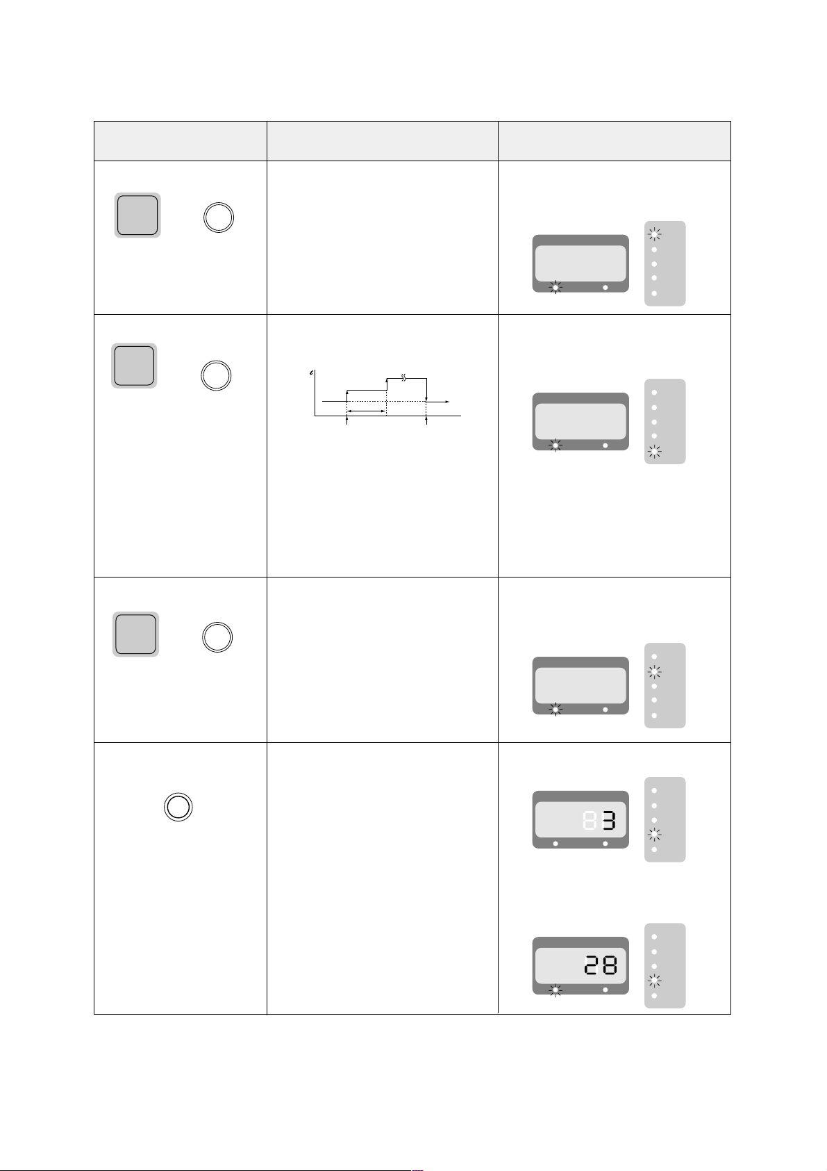
13
FUNCTION
FAN MODE
Push the ‘MODE’ button until
‘FAN’ lamp lights.
ON/OFF ENERGY SAVE
Push the ‘ENERGY SAVE’
button.
TURBO MODE
Push the ‘MODE’ button until
‘TURBO’ lamp lights.
OFF TIMER
Push the ‘TIMER/CANCEL’
button when unit is working.
(REMOCON ONLY)
OPERATION
1. The Fan works only.
2. In this mode, the unit circulate room air.
3. Fan speed can be changed.
1. Desired temperature is changed as
follows by pushing ‘ENERGY SAVE’
button.
2. When the ‘ENERGY SAVE’ button is
pushed, the fan speed goes to ‘Low’
3. When the ‘ENERGY SAVE’ function
is canceled by pushing ‘ENERGY
SAVE’ button once again, the
desired temperature is return to the
former desired temperature.
1. Fan speed is set to ‘HIGH’ and
desired temperature to 18°C (64°F).
1. Timer is set to as follows by pushing
“TIMER/CANCEL” button.
(1hr→2hr→3hr→4hr→5hr→6hr→8hr→
10hr→12hr→16hr→20hr→24hr→cancel)
2. Unit is off after timer is over.
3. If you want to cancel timer, push this
button again at any time.
DISPLAY
1. Current room temperature is displayed.
2. ‘FAN’ lamp lights.
3. ‘ROOM TEMP’ lamp lights.
1. Current room temperature is displayed.
2. ‘ENERGY SAVE’ lamp lights.
3. ‘ROOM TEMP’ lamp lights.
1. Current room temperature is displayed.
2. ‘TURBO’ lamp lights.
3. ‘ROOM TEMP’ lamp lights.
1. ‘TIMER’ lamp lights.
2. Set time is displayed.
3. After a few seconds, display is
changed to current room temprature.
and ‘ROOM TEMP’ lamp lights.
ENERGY
SAVE
ENERGY
SAVE
MODE
MODE
TIMER/
CANCEL
MODE
MODE
or
or
or
hr
‘ENERGY SAVE’ON‘ENERGY SAVE’
OFF
1hr
+1°C
+1°C
-2°C
ROOM TEMP DESIRED TEMP
FAN
TURBO
COOLING
TIMER
ENERGY
SAVE
ROOM TEMP DESIRED TEMP
FAN
TURBO
COOLING
TIMER
ENERGY
SAVE
ROOM TEMP DESIRED TEMP
FAN
TURBO
COOLING
TIMER
ENERGY
SAVE
ROOM TEMP DESIRED TEMP
FAN
TURBO
COOLING
TIMER
ENERGY
SAVE
ROOM TEMP DESIRED TEMP
FAN
TURBO
COOLING
TIMER
ENERGY
SAVE
Page 14
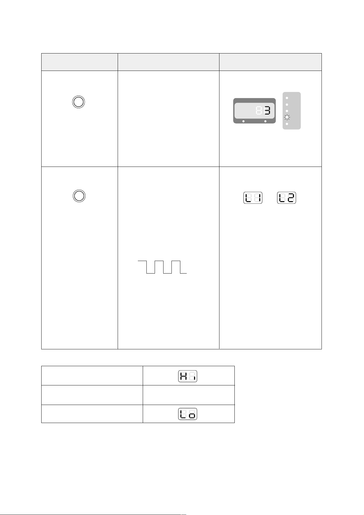
14
FUNCTION
ON TIMER
Push the ‘TIMER/CANCEL’
button when unit is off.
(REMOCON ONLY)
SLEEP MODE
Push the ‘SLEEP’ button in
‘COOLING’ mode.
(REMOCON ONLY)
OPERATION
1. Timer is changed to as follows by
pushing “TIMER/CANCEL” button.
(1hr→2hr→3hr→4hr→5hr→6hr→8hr→
10hr→12hr→16hr→20hr→24hr→cancel)
2. The unit starts working after set time
is over in cooling mode with last
temperature set.
3. If you want to cancel timer, push this
button again at any time.
1. SLEEP MODE is changed as follows
by pushing “SLEEP” button.
(L1→L2→cancel)
* L1 Mode
– The unit is off after 4 hours.
– The desired Temp is increased 3°C
(5.4°F) for 4 hours.
– Fan speed is set to ‘LOW’.
* L2 MODE
– The unit works as follow.
– Fan speed is set to ‘LOW’.
2. Set proper desired room temperature,
fan speed.
3. This mode can be selected in
‘COOLING’ mode only.
DISPLAY
1. ‘TIMER’ lamp lights.
2. Setting time is displayed.
3. After a few seconds, display is
changed to current room
temperature. and ‘ROOM TEMP’
lamp lights.
1. ‘L1’ or ‘L2’ is displayed.
2. ‘ROOM TEMP’ and ‘DESIRED
TEMP’ lamp is off.
• ROOM TEMPERATURE DISPLAY.
Over 45°C or 100°F
5°C~45°C or 41°F~99°F
Below 5°C (41°F)
DISPLAY TEMPERATURE
ON
OFF
2hr 2hr 2hr 2hr 2hr
+1°C+1°C
ROOM TEMP DESIRED TEMP
FAN
TURBO
COOLING
TIMER
ENERGY
SAVE
TIMER/
CANCEL
SLEEP
Page 15
15
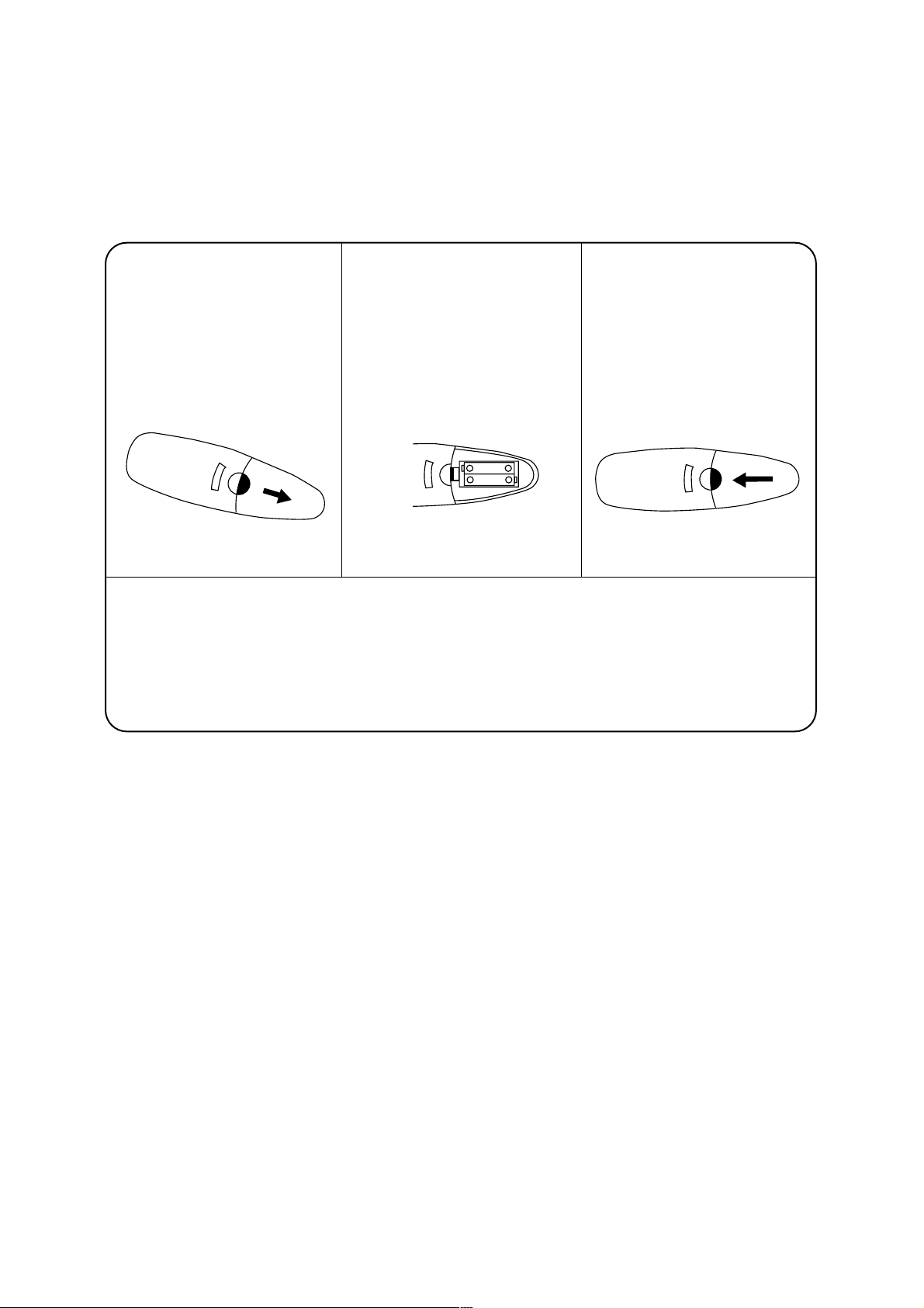
• HOW TO INSERT BATTERIES
Remove the COVER from
the back of the remote
controller.
• Slide the Cover according
to the arrow direction
Insert two battaries.
• Be sure that the (+) and (–)
directions are correct
• Be sure that both batteries
are new
Re-attach the cover.
• Slide it back into position
• Do not use rechargeable batteries such batteries differ from standard dry cells in shape, dimensions,
and performance.
• Remove the batteries from the remote controller if the air conditioner is not going to be used for an
extended length of time.
1 2 3
– +
– +
Page 16

16
• CHANGING AIR FLOW DIRECTION
Air flow deflectors divert air from center flow to left or right and up or down.
Adjust deflectors for desired air flow pattern.
• AIR FLOW AROUND UNIT
Check in door grill and outdoor louvers for air flow obstructions. Do not block air flow to and from unit. The
outdoor coil should be checked and periodically cleaned for debris that may collect and block unit air flow.
If air flow is obstructed or deflected back into unit, the compressor may cycle on and off rapidly, causing
early compressor failure.
• DRAIN HOLE AND WATER DRIPPING OUTSIDE
Locate drain hole at the rear or on the bottom of unit. Water in base pan is picked up by the fan blade and
thrown onto the warm outdoor coil where it evaporates. The air conditioner must be installed level or tilted
slightly to the outside for proper water disposal. On exceptionally hot and humid days the air conditioner
may permit excess water to pass thru rear drain hole or overflow. This should be considered normal.
GENERAL INFORMATION
Page 17
17
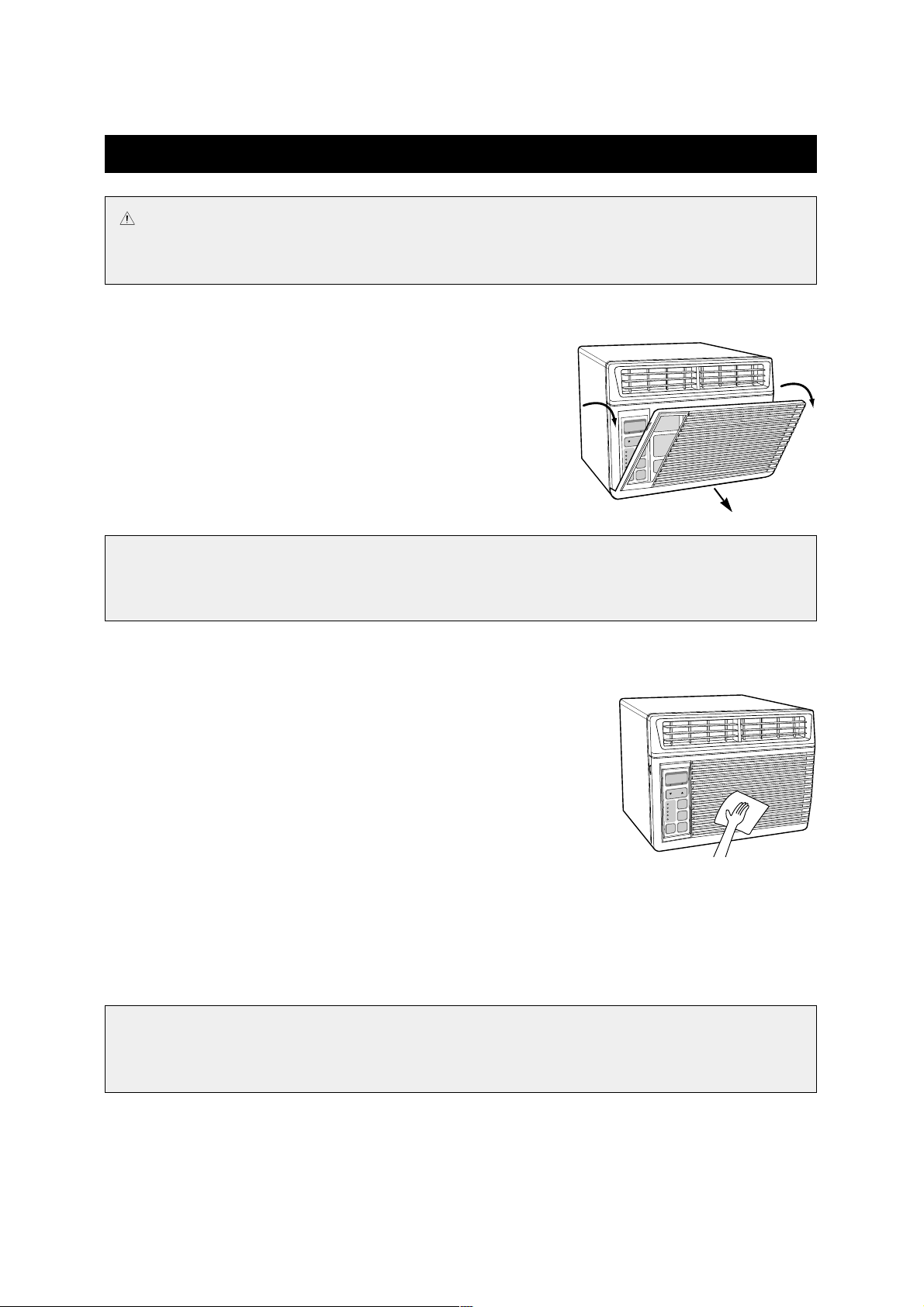
• AIR FILTER
Clean the air filter, which removes dust inside the room.
It should be washed at least once every week during operation.
1. Open the inlet grille downward by pulling out the both side of the
inlet grille.
2. Using the tab, pull up slightly on the filter to release it and pull it
down.
3. Clean Air Filter with a vacuum cleaner or lukewarm, soapy water.
4. Shake it when clean to remove moisture completely. Reinstall.
• CLEANING THE AIR CONDITIONER
1. At least once a year, remove cabinet and thoroughly clean air conditioner.
Have the unit inspected by an authorized service man to ensure unit is
functioning properly.
2. Wash air conditioner with lukewarm, soapy water as needed.
Rinse and dry thoroghly.
3. If using concentrated liquid detergent, dilute in warm water first.
4. Front grill may be wiped off with a cloth dampened in a mild detergent
solution.
5. Cabinet may be washed with mild soap or detergent and lukewarm water, then polished with liquid wax for
appliances.
6. Condenser and Evaporator coils should be cleaned at the beginning of each cooling season. Use a soft
brush or vacuum cleaner to clean them, making sure that the Condenser and Evaporator coils are not
damaged.
7. Do not use abrasive cleaners. These items scrach, crack and discolor surfaces.
CARE AND MAINTENANCE
CAUTION
To avoid death or personal injury due to electrical shock, turn fan control OFF and unplug power cord
before cleaning or performing maintenance. After cleaning or performing maintenance, reconnect power.
NOTE
A dirty Air Filter reduces air flow and the cooling capacity.
Do not operate unit without Air Filter.
NOTE
To assure continued peak efficiency, condenser coils (weather side of unit) should be checked
periodically and cleaned if clogged with soot or dirt from the atmosphere.
Page 18
18
• ELECTRICAL GROUNDING INSTR UCTIONS
This appliance is equipped with a three-prong(grounding) plug for protection against possible shock hazards. If
a two-prong wall receptacle is encountered, the customer is required to contact a qualified electrician and have
the two-prong wall receptacle replaced with a properly grounded three-prong wall receptacle in accordance
with the National Electrical Code.
• USE OF EXTENSION CORD
Because of potential safety hazards under certain condition, we strongly recommend against the use of an
extension cord. However, if you still elect to use an extension cord, it is absolutely necessary that it will be a UL
listed 3-wire grounding type appliance extension cord rated has a 3-blade grounding plug and a 3-slot
receptacle that will plug into the appliance. The marked rating of the extension cord should be 125V/13A(Min.).
ELECTRICAL REQUIREMENTS
WARNING :
To avoid death, personal injury or properly damage due to electrical shock, this unit must be
grounded.
Do not under any circumstances cut or remove the round grounding prong from the plug.
Do not use a two prong adapter.
WARNING :
To avoid death, personal injury or properly damage due to electrical shock, do not use an
extension cord or pinch the power cord.
Do not remove the warning tag from the power cord.
Page 19

19
BEFORE CALLING FOR SERVICE
When you find something wrong with your room air conditioner, please carefully check the following items.
If you are unable to find the cause of trouble, contact your service dealer.
Difficulty
• Air conditioner does
not operate.
• Little or no cooling
• Noisy unit
• Ordors from unit.
• Water in base pan.
Possible Cause
• No power to unit.
• Compressor lockout on initial
plug in.
• Dirty air filter
• Is there anything blocking the
front?
• Air conditioner undersized for
application.
• Loose parts
• Weak building construction.
• Water hitting fan.
• Mold, mildew or algae formation
on wet surfaces.
• Normal for operation in humid
areas.
Suggested Solution
•
Confirm power cord is plugged in.
•
Verify main power switch
(main circuit breaker) or fuse of
the unit is good.
• Wait 3 to 4 minutes and restart
the unit.
• Clean air filter.
• When blocked by curtains,
blinds, or furnitures, etc., the air
flow is restricted and cooling
performance is affected.
• Check with dealer to determine
proper unit capacity for
application.
•Tighten any loose parts.
• Provide additional support.
• Normal in high humidity.
• Stop noise by allowing water to
drain from base fan through
drain hole.
• Place algaecide tablet in base
pan
• Remove water in base pan
through drain hole.
• Water in base pan is picked up
by the fan blade and thrown onto
the warm outdoor coil where
water then evaporates.
Page 20
Limited Warranty
DAEWOO ELECTRONICS CORPORATION OF AMERICA warrants the following
window room air-conditioner to be free from defective material and workmanship and
agrees to remedy any such defect or to furnish a new part (at the Company’s option) in
exchange for any part of any unit of its manufacture which under normal installation,
use and service disclosed such defect, provided the unit is delivered by the owner to
store or dealer where purchased or Daewoo authorized service center. To establish
and receive warranty service at our store, dealer or our authorized service center, a
sales receipt or bill of sales is required for proof of purchase.
This warranty does not extend to any of our electronic products which have been
subjected to misuse, neglect, accident, incorrect wiring not our own, improper
installation, unauthorized modification, or to use in violation of instructions furnished by
us, nor units which have been repaired or altered outside of our factory, nor to cases
where the serial number thereof has been removed, defaced, or changed.
This warranty is in lieu of all warranties expressed or implied and no representative or
person is authorized to assume for us any other liability in connection with the sales of
our electronic products.
Over the counter exchange for units that are initially defective. Initial defective is
described as when the dealer opens the unit and finds that it is inoperative or an
individual customer opening a new unit and finding that it is initially defective. This unit
may be returned to the factory by the dealer for exchange. Under no circumstances
will an individual customer be permitted to return defective unit directly to factory.
Exchange must be directly with the dealer. When this unit is returned to dealer, a copy
of the purchase evidence stating the date of purchase is to be put in the individual box
for dealer’s further control with the factory.
MODEL PARTS LABOR COMPRESSOR
DWC-064R
1 year 1 year 5 years
DWC-084R
Note: The warranty service center list is constantly changing with the addition of our
current qualified service centers. If there is inadequate or no local service facility,
subject individual customer will call DAEWOO on the toll free number
1-800-DAEWOO8(1-800-323-9668) to be provided with further informations.
Page 21

MODEL #: DWC-064R
DWC-084R
ROOM AIR CONDITIONER
USE & CARE MANUAL
WINDOW TYPE ROOM AIR CONDITIONER
W1
R
C
US
LISTED
UL and
CUL listed
Please read carefully and thoroughly this manual before
operating the unit.
If you still have any difficulties or problems, consult your
dealer for help or ELECTRONICS.
Please keep this manual well.
 Loading...