

Daewoo DWC-121CS, DWA-121C, DWC-124C, DWC-124CS, DWA-121CS Service Manual
...
Manual de servicio
Acondicionador de Aire Tipo Ventana
Modelo:

1
TABLE OF CONTENTS
1. PRECAUTION...............................................................................2
2. GENERAL SPECIFICA TIONS................................................................3
3. NAMES OF MAJOR COMPONENTS.......................................................4~5
4. FUNCTION OF MAIN COMPONENTS ........................................................6
5. GENERAL INFORMA TIONS .................................................................7
6. CARE AND MAINTENANCE .................................................................8
7. TROUBLE SHOO TING GUIDE ...............................................................9
8. HOW T O DISASSEMBLE...................................................................11
9. WIRING DIAGRAM.........................................................................14
10. REFRIGERANT CYCLE ...................................................................15
11. EXPLODED DIAGRAM AND PARTS LIST ..................................................16

2
1. PRECA UTION
Please observe the following instructions.
1. Turn off unit.
Make sure the unit is OFF and the AC cord is unplugged before repairing or servicing.
2. In case of checking the circuit una v oidab ly while the unit is connected with po wer sour ce, be careful
not to connect with the part of electric charge.
You may cause electric shock.
3. Use of proper part if you need to replace the part, be sure to use genuine part of servicing model.
Do not repair or replace the electric contact part.
Consumer must not repair the unit, because it is dangerous.
4. Use of proper tool.
You must use the proper tool to repair the unit, and use the measuring appliance adjusted accurately.
5. Damage of electric wire and power cord when servicing.
Check electric wire and a surely replace a damage electric wire and a damage power cord.
6. Never use connecting the middle of wire, after cutting the middle of wire.
It may cause a fire and trouble.
7. Checking the insulation resistance.
After you complete the assembly of unit, surely check the insulation resistance.
Confirm that the insulation resistance of the power line and the ground terminal is over 30MΩ by measuring insulation
resistance.
8. Checking the ground.
After checking the ground, servicing it completely.
9. Checking the installation.
After checking the installation, servicing it completely.
10. Care children.
When servicing, do not make the children approach the air-conditioner.
3
ITEM
MODEL
Function
Power source
AC 115V, 60Hz
Btu/h 12,100 12,000 12,000 11,700 12,000 11,500 14,018 14,000
Kcal/h 3,050 3,024 3,024 2,950 3,024 2,898 3,533 3,528
Btu/wh 10.1 10.2 10.1 9.9 10.0 10.0 9.4 9.8
Kcal/wh 2.55 2.57 2.55 2.49 2.52 2.52 2.38 2.47
Dehumidification
Pts/h 3.40 3.61 3.14 3.30 2.66 2.71 4.04 3.93
g/h 1,545 1,640 1,427 1,500 1,209 1,232 1,836 1,786
Power Input (W)
1,200 1,175 1,184 1,180 1,150 1,150 1,487 1,420
Running Current (A)
11.5 5.5 5.5 5.2 5.4 5.4 6.7 6.5
Type
Rotary
Compressor Model QK164CN12 QK164KN12 RBA115A001 QK196PN13A RBB110A011 RBF110A011 QJ196KC23 RCA135A001
Capacitor 40µF/370VAC 35µF/400VAC 30µF/400VAC 35µF/400VAC
Model
Motor
Capacitor
12µF/370VAC
Indoor-Fan
Blower-Fan
Outdoor-Fan
Propeller-Fan
Control
Capillary
Charge Q’ty (g) 24.0 oz (680g) 26.1 oz (740g) 27.9 oz (790g) 25.7 oz (730g) 24.3 oz (690g) 26.8 oz (760g) 27.9 oz (790g) 27.5 oz (780g)
Dimensions
Unit (WxHxD)
Packing (WxHxD)
Weight
Net Weight
88 lbs (38.8Kg)
Gross Weight
89 lbs (40.3 Kg)
2. GENERAL SPECIFICATIONS
A2925CA070/OBM-2501P2
5µF/400VAC
25µF/370VAC
AM12 DWD11/OBM-2503U1
4µF/370VAC
88 lbs (38.8Kg)
89 lbs (40.3 Kg)
90.2 lbs (39.8Kg)
97.5 lbs (43 Kg)
23.6(W) x 14.9(H) x 21.0(D) Inch (600(W) x 380(H) x 535(D) mm)
26.1(W) x 18.1(H) x 22.6(D) inch (663(W) x 460(H) x 573(D) mm)
92 lbs (42Kg)
96 lbs (43.5Kg)
AC 208~230V, 60Hz
AC 220~240V, 50Hz AC 220~230V, 50Hz
AC 240V, 50Hz
25µF/370VAC
AM12DWD12/OBM-2502U1
5µF/370VAC
AC 208~230V, 60Hz
Energy
Efficiency
Ratio
Electrical
Data
Refrigerant
(R-22)
AM12DWD10/
OBM-2501K1
Cooling only
Cooling
Capacity
DWC-121C/CS
(DWC-124C/CS)
DWA-121C/CS
DWA-122C/CS
(DWA-124C/CS)
DWB-121C/CS
DWB-122C/CS
(DWB-124C/CS)
DWB-123C/CS DWA-150C/CS
DWA-151C/CS
(DWA-152C/CS)
• DW A-124C/CS , D WB-124C/CS , D WC-124C/CS , D WA-152C/CS;
Except detachable Double Grille Front, the general spec of this model is same to one of the old models.
4
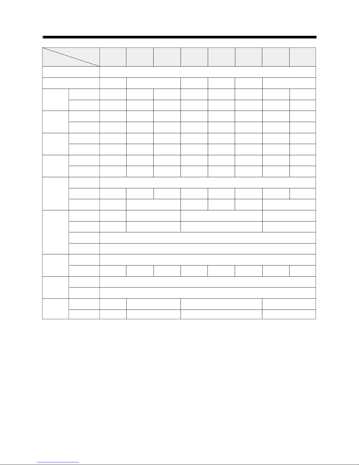
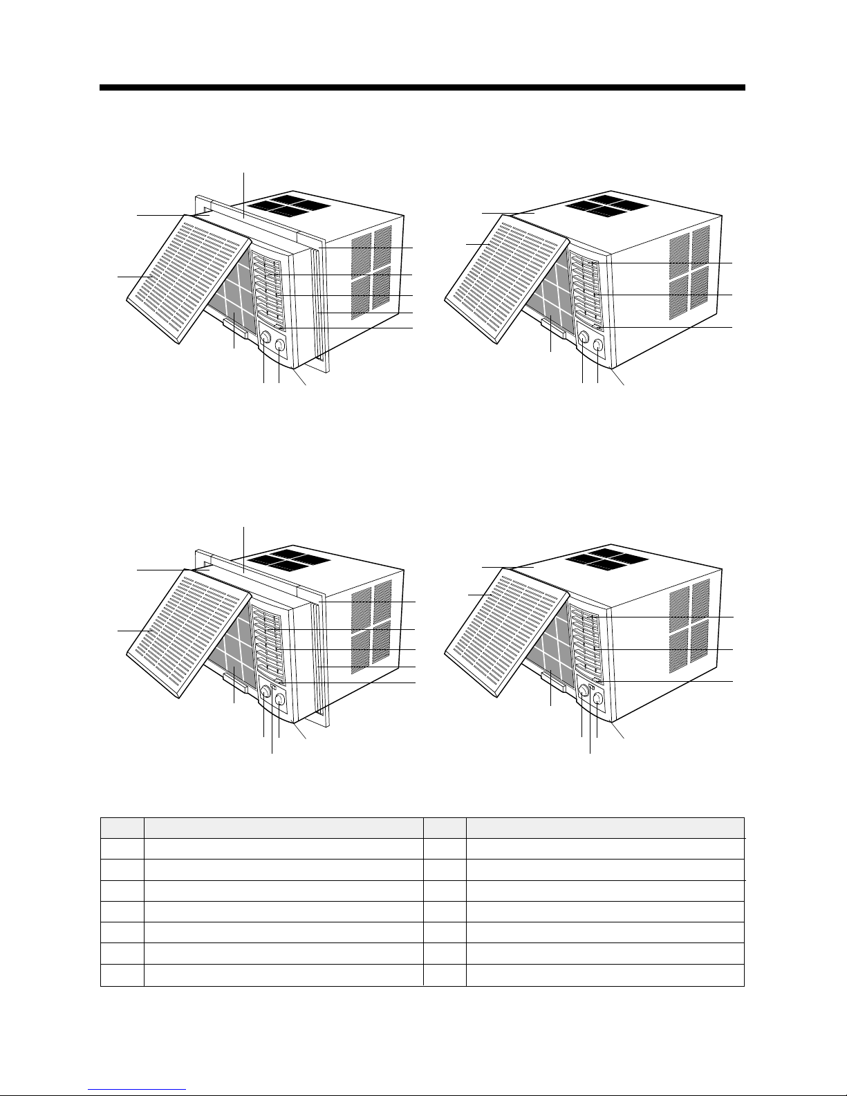
3.NAMES OF MAJOR COMPONENTS
6
12
5
2
1
3
7
4
8
11
10
9
6
12
5
2
1
3
7
4
8
NO PART NAME
1 AIR FILTER
2 GRILL FRONT
3 CABINET
4 BLADE VERTICAL
5 KNOB THERMOSTAT
6 KNOB SELECTOR
NO PART NAME
7 BLADE HORIZENTAL
8 AIR VENT
9 PLATE WINDOW TOP
10 FRAME WINDOW KIT
11 SHUTTER WINDOW
12
AUTO LOUVER S/W (DW✻-121CS/DW✻-122CS/DWB-123CS/DWA-150CS/DWA-151CS)
• DW✻-121CS / DW✻-122CS / DWB-123CS / DWA-150CS / DWA-151CS
6
5
2
1
3
7
4
8
11
10
9
6
5
2
1
3
7
4
8
• DW✻-121C / DW✻-122C / DWB-123C / DWA-150C / DWA-151C
NOTE: ✻ → A or B or C
5
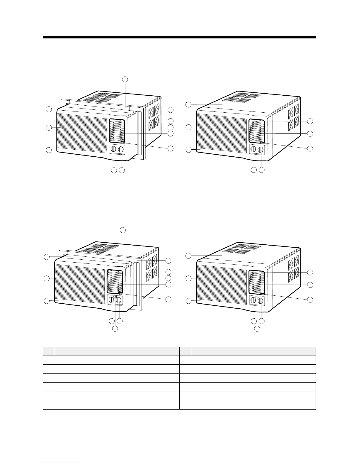
NO PART NAME
1 AIR FILTER
2 GRILLE
3 CABINET
4 BLADE VERTICAL
5 KNOB THERMOSTAT
6 KNOB SELECTOR
7 BLADE HORIZENTAL
NO PART NAME
8 AIR VENT
9 FRAME GRILLE
10 FRAME GUIDE TOP
11 FRAME WINDOW KIT
12 SHUTTER WINDOW
13
AUTO LOUVER S/W (DW✽-124CS/DWA-152CS)
• DW✽-124CS / DWA-152CS
NOTE: ✽→A or B or C
4
0
q
7
w
8
3
2
56
1
9 9
3
4
8
2
7
1
56
9
9
4
0
q
7
w
8
3
2
56
1
e
3
4
8
2
7
1
56
e
• DW✽-124C / DWA-152C
NOTE: ✽→A or B or C
6
4. FUNCTION OF MAIN COMPONENTS
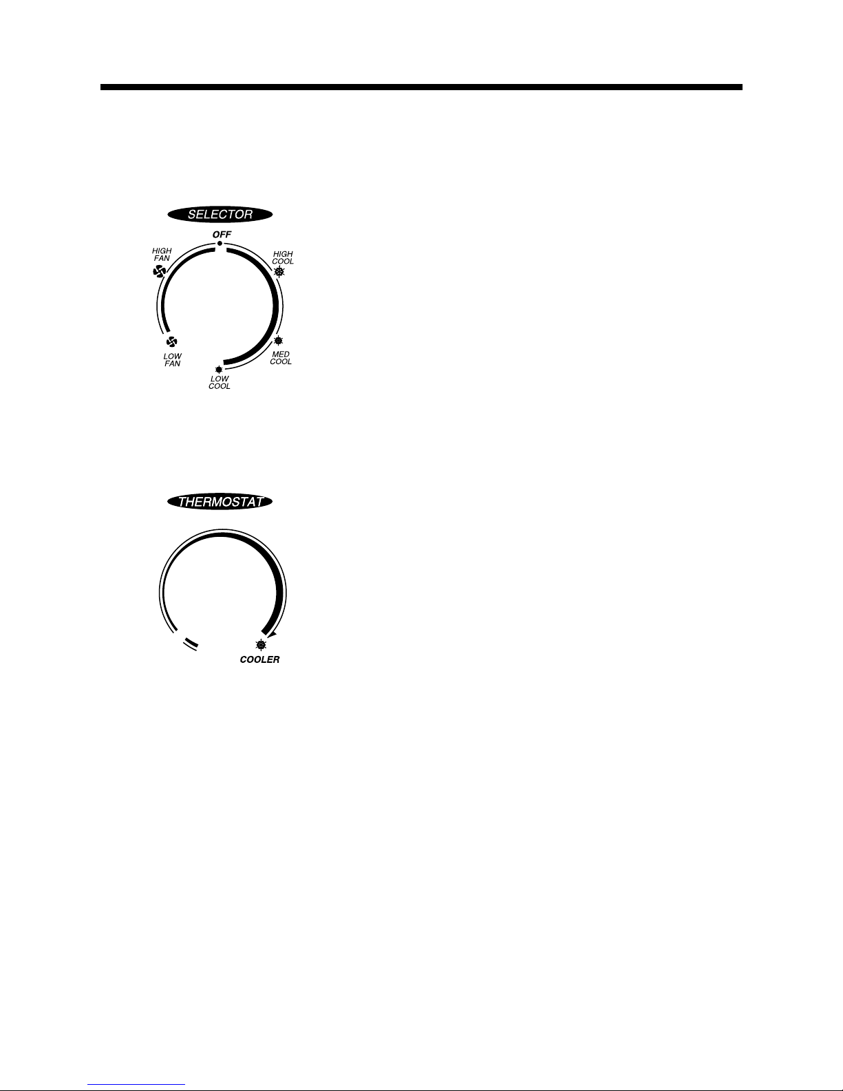
1. ROTARY SWITCH (SELECT OR)
Please refer to the part of selector in the chapter 9 (Wiring Diagram).
The rotary switch (selector) controls the fan motor’s rotation speed, and has six positions.
The function of the six position is as follow.
• OFF: This position stops all operations of the air conditioner.
• HIGH COOL: This position provides the maximum air flow for rapid
cooling, dehumidifying and dust removing operations.
(Use this position on sultry summer days.)
• MED COOL: This position provide the medium air flow for cooling
dehumidifying and dust removing operations
• LOW COOL: This position provides the minimum air flow for quiet
cooling, dehumidifying operations.
(Use this position on suitable for night-time.)
• HIGH FAN: This position provides the maximum air fiow alone fan
operation without cooling operation.
• LOW FAN: This position provides the minimum air flow air flow alone
fan operation without cooling operation.
2. THERMOSTAT (TEMPERATURE CONTROL)
• The Thermostat automatically starts and stops operation in order to keep
the room temperature at a proper level, and this results in efficient use of
power and economical cooling.
• Turn clockwise for a cooler room temperature.
• Turn counter-clockwise for a warmer room temperature.
3. MOT OR
The motor is used to rotate the indoor and outdoor fan so that the room air can be recirculated.
4. F AN
• BLOEWR FAN: The Blower draws hot air from the room through the Evaporator and then discharges it back into the
cool air. It circulates the room air.
• PROPELLER FAN: The propeller draws outdoor air through louvering and cools Condenser, and then blows the hot
air out.
5. CAPACITOR
The Capacitor enlarges the difference of phase between main coil and sub coil so that the Compressor and Fan Motor
starts well.
6. ACCUMULATOR
The Accumulator blocks the unflow of liquid refrigerant and impurities into the Compressor.

7
5. GENERAL INFORMATIONS
1. CHANGING AIR FLOW DIRECTION
Air flow deflectors divert air from center flow to left or right and up or down.
Adjust deflectors for desired air flow pattern.
2. AIR FLOW AR OUND UNIT
Check in door grill and outdoor louvers for air flow obstructions. Do not block air flow to and from unit. The outdoor coil
should be checked and periodically cleaned for debris that may collect and block unit air flow. If air flow is obstructed
or deflected back into unit, the compressor may cycle on and off rapidly, causing early compressor failure.
3. Electrical Grounding Instructions.
This appliance is equipped with a three-prong(grounding) plug for protection against possible shock hazards. If a twoprong wall receptacle is encountered, the customer is required to contact a qualified electrician and have the twoprong wall receptacle replaced with a properly grounded three-prong wall receptacle in accordance with the National
Electrical Code.
4. USE OF EXTENSION CORDS
Because of potential safety hazards under certain conditions we strongly recommend against the use of an extension
cord. However, if you still elect to use an extension cord, it is absolutely necessary that it be a UL listed 3-wire
grounding type appliance extension cord rated has a 3-blade grounding plug and a 3-slot receptacle that will plug into
appliance.
5. DRAIN HOLE AND WATER DRIPPING OUTSIDE
Locate drain hole at the rear of unit. Water in base pan is picked up by the fan blade and thrown onto the warm
outdoor coil where it evaporates. The air conditioner must be installed level or tited or slightly to the outside for proper
water disposal. On exceptionally hot and humid days the air conditioner may permit excess water to pass thru rear
drain hole or overflow. This should be considered normal.
 Loading...