

Page 1

S/M No. : TCN011NEF0
Service Manual
Color Television
CHASSIS : CN-011
Model :
DTQ-29S3FC
DTQ-26S3FC
DTQ-26S3FCM
DTQ-29S3FC
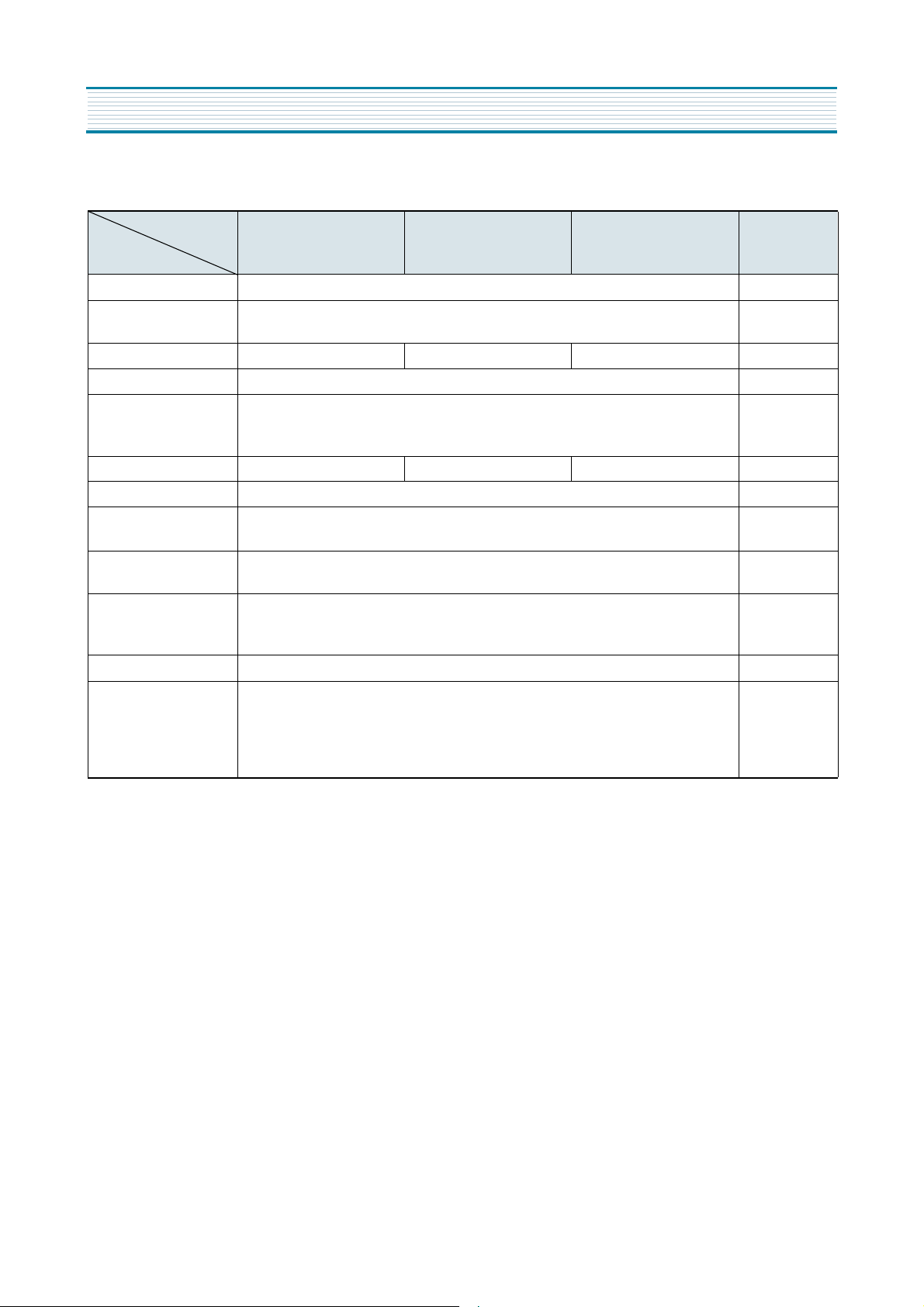
SPECIFICATIONS
MODEL
ITEMS
TV STANDARD
POWER INPUT
POWER CONSUMPTION
TUNING SYSTEM
TUNING RANGES
SOUND OUTPUT
SPEAKER
ANTENNA INPUT
IMPEDANCE
AUXILIAR Y
INPUT TERMINAL
INTERMEDIA TE
FREQUENCIES
REMOTE CONTROL
SPECIAL FUNCTIONS
DTQ-26S3FC
DTQ-29S3FC DTQ-26S3FC DTQ-26S3FCM
97W 95W 90W
1.8W 1.8W 1.8W+1.8W 1.8W
U.S.A
Canada
DTQ-26S3FCM
NTSC-M
AC 120V 60Hz
Frequency Synthesizer(FS)Tuning System
VHF:2~13(12)
UHF:14~69(65)
CATV:1~125(125)
3W 8ohm
75ohm Unbalanced
Front : Video, Audio
Rear:Video, Audio
Picture IF Carrier Frequency :45.75MHz
Sound IF Carrier Frequency :41.25MHz
Color Sub-Carrier Frequency :42.17MHz
R-43A01
3-Language OSD
With CAPTION
Wake-up On/Off Time
Sleep Timer
Power Restore
D AEW OO ELECTR ONICS CO., LTD
http : //svc.dwe .co.kr
Aug. 2000
Page 2

TABLE OF CONTENTS
SAFETY INSTRUCTION................................................................................................... 2
SPECIFICATIONS ......................................................................................................... 4
CIRCUIT BLOCK DIAGRAM .......................................................................................... 5
ALIGNMENT INSTRUCTIONS.......................................................................................... 6
1. SERVICE MODE ADJUSTMENTS........................................................................................................ 6
2. ASSEMBLY ADJUSTMENTS................................................................................................................ 7
SCHEMATIC DIAGRAM................................................................................................ 11
EXPLODED VIEW......................................................................................................... 12
PRINTED CIRCUIT BOARD............................................................................................. 15
SERVICE PARTS LIST ..................................................................................................... 16
1. DIFFERENT PARTS LIST ..................................................................................................................... 23
APPENDIX ( Appendix is provided only by internet [http://svc.dwe.co.kr] )
IC DESCRIPTION......................................................................................................... 1
TROUBLE SHOOTING CHARTS ...................................................................................... 13
1
Page 3
PRODUCT SAFETY SERVICING GUIDELINES FOR COLOR TELEVISION RECEIVERS
CAUTION : Do not attempt to modify this product in any way. Unauthorized modifications will not only void the warranty, but may lead to
your being liable for any resulting property damage or user injury.
Service work should be performed only after you are thoroughly
familiar with all of the following safety checks and servicing guidelines. To do otherwise, increases the risk of potential hazards and
injury to the user.
SAFETY CHECKS
After the original service problem has been corrected, a check should
be made of the following:
SUBJECT : FIRE & SHOCK HAZARD
1. Be sure that all components are positioned in such a way as to
avoid possibility of adjacent component shorts. This is especially
important on those chassis which are transported to and from the
repair shop.
2. Never release a repair unless all protective devices such as insulators, barriers, covers, shields, strain reliefs, and other hardware
have been reinstalled per original design.
3. Soldering must be inspected to discover possible cold solder joints,
frayed leads, damaged insulation (including A.C. cord), solder
splashes or sharp solder points. Be certain to remove all loose foreign particals.
4. Check for physical evidence of damage or deterioration to parts
and components, and replace if necessary follow original layout,
lead length and dress.
5. No leads or components should touch a receiving tube or a resistor
rated at 1 watt or more. Lead tension around protruding metal surfaces must be avoided.
6. All critical components such as fuses, flameproof resistors, capacitors, etc. must be replaced with exact factory types. Do not use
replacement components other than those specified or make
unrecommended circuit modifications.
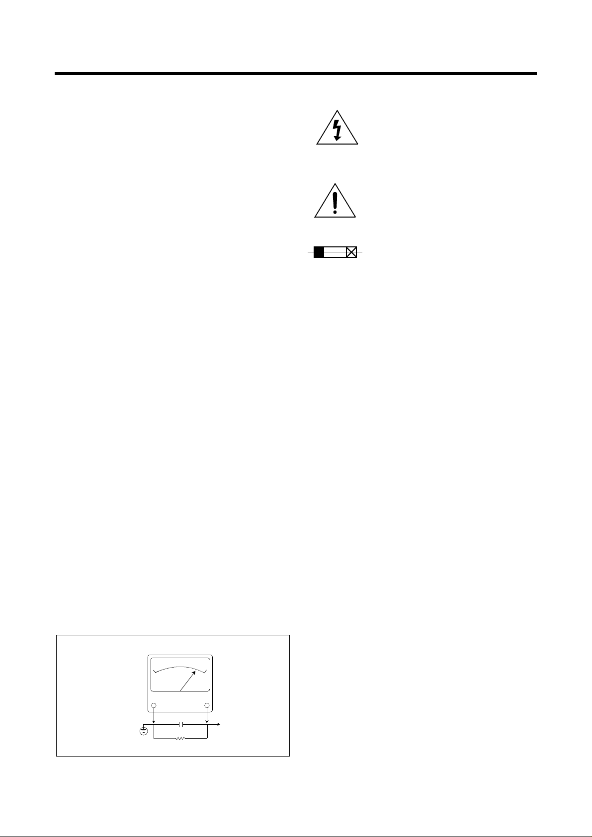
7. After re-assembly of the set always perform an A.C. leakage test
on all exposed metallic parts of the cabinet, (the channel selector
knob, antenna terminals, handle and screws) to be sure the set is
safe to operate without danger of electrical shock. Do not use a
line isolation transformer during this test. Use an A.C. voltmeter,
having 5000 ohms per volt or more sensitivity, in the following
manner : connect a 1500 ohm 10 watt resistor, paralleled by a 15
mfd. 150V A.C. type capacitor between a known good earth
ground (9water pipe, conduit, etc.) and the exposed metallic parts,
one at a time. Measure the A.C. voltage across the combination of
1500 ohm resistor and 0.15 MFD capacitor. Reverse the A.C. plug
and repeat A.C. voltage measurements for each exposed metallic
part. Voltage measured must not exceed 0.75 volts R.M.S. This
corresponds to 0.5 milliamp A.C. Any value exceeding this limit
constitutes a potential shock hazard and must be corrected immediately.
A.C. VOLTMETER
GRAPHIC SYMBOLS :
The lightning flash with arrowhead symbol,
within an equilateral triangle, is intended to alert
the service personnel to the presence of uninsulated “dangerous voltage” that may be of sufficienty magnitude to constitute a risk of electric
shock.
The exclamation point within an equilateral triangle is intended to alert the service personnel
to the presence of important safety information
in service literature.
Fuse symbol is printed on pcb adjacent to the
fuse, with “RISK OF FIRE REPLACE FUSE AS
MARKED”. The symbol is explained in the service manual with the following wording or equivalent.
“CAUTION :
FOR CONTINUED PROTECTION AGAINST FIRE
HAZARD, REPLACE ONLY WITH SAME TYPE (5A, 125V)” and
“
ATTENTION
: AFIN D’ASSU UNE PROTECTION PERMANENTE
CONTRE LES RISQUES D’INCENDIE, REMPLACER UNIQUEMENT PAR UN FUSIBLE DE MEME TYPE ET DE ”5A, 125V”.
SUBJECT : X-RADIATION
1. Be sure procedures and instructions to all service personnel cover
the subject of X-rays in current T.V. receivers is the picture tube.
However, this tube does not emit X-rays when the high voltage is
at the factory specified level. The proper value is given in the applicable schematic. Operation at higher voltages may cause a failure
of the picture tube or high voltage supply and, under certain circumstances, may produce radiation in excess of desirable levels.
2. Only factory specified C.R.T. anode connectors must be used.
Degaussing shields also serve as X-ray shield in color sets.
Always re-install them.
3. It is essential that the serviceman has available an accurate and
reliable high voltage meter. The calibration of the meter should be
checked perio - dically against a reference standard. Such as the
one available at your distributor.
4. When the high voltage circuitry is operating properly there is no
possibility of an X-radiation problem. Every time a color chassis is
serviced, the brightness should be run up and down while monitoring the high voltage with a meter to be certain that the high voltage
does not exceed the specified value and that it is regulating correctly. We suggest that you and your service organization review
test procedures so that voltage regulation is always checked as a
standard servicing procedure. And that the high voltage reading be
recorded on each customer’s invoice.
5. When troubleshooting and making test measurements in a receiver
with a problem of excessive high voltage, avoid being unnecessarily
close to the picture tub eand the high voltage compartment.
Do not operate the chassis longer than is necessary to locate the
cause of excessive voltage.
6. Refer to HV, B+and Shutdown adjustment procedures described in
the appropriate schematic and diagrams(where used).
Good earth ground,
such as the water
pipe, conduit, etc.
0.15 uF
1500 OHM
10WATT
Place this probe
on each exposed
metal part.
2
Page 4

SUBJECT : IMPLOSION
1. All direct viewed picture tubes are equipped with an integral implosion protection system, but care should be taken to avoid damage
during installation. Avoid scratching the tube. If scratched, replace
it.
2. Use only recommended factory replacement tubes.
SUBJECT : TIPS ON PROPER INSTALLATION
1. Never install any receiver in closed-in recess, cubbyhole or closely
fitting shelf space over, or close to heat duct, or in the path of
heated air flow.
2. Avoid conditions of high humidity such as : Outdoor patio installations where dew is a factor. Near steam radiators where steam
leakage is a factor, etc.
3. Avoid placement where draperies may obstruct rear venting. The
customer should also avoid the use of decorative scarves or other
coverings which might obstruct ventilation.
4. Wall and shelf mounted installations using a commercial mounting
kit, must follow the factory approved mounting instructions. A
receiver mounted to a shelf or platform must retain its original
feet(or the equivalent thickness in spacers) to provide adequate
are flow across the bottom, bolts or screws used for fasteners
must not touch and parts or wiring. Perform leakage test on customized installations.
5. Caution customers against the mounting of a receiver on sloping
shelf or a tilted position, unless the receiver is properly secured.
6. A receiver on a roll-about cart should be stable on its mounting to
the cart. Caution the customer on the hazards of trying to roll a cart
with small casters across thresholds or deep pile carpets.
7. Caution customers against the use of a cart or stand which has not
been listed by underwriters laboratories, inc. For use with their
specific model of television receiver or generically approved for
use with T.V.’s of the same or larger screen size.
3
Page 5
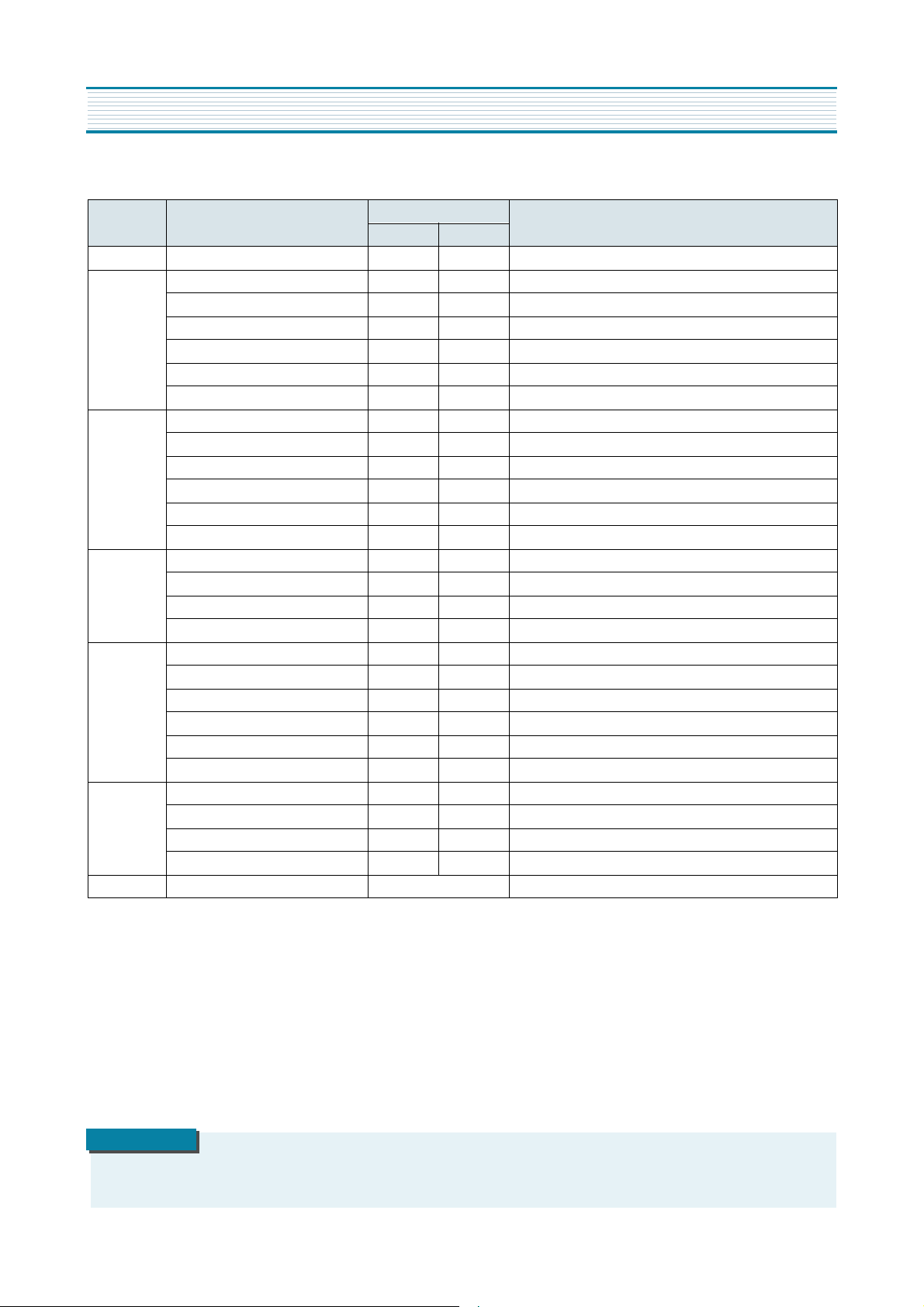
SPECIFICATIONS
MODEL
DTQ-29S3FC DTQ-26S3FC DTQ-26S3FCM REMARKS
ITEMS
TV STANDARD NTSC-M
POWER INPUT
POWER CONSUMPTION 97W 95W 90W
TUNING SYSTEM Frequency Synthesizer ( FS ) Tuning System
TUNING RANGES
SOUND OUTPUT 1.8W31.8W 1.8 W+1.8 W 1.8W
SPEAKER 3 W 8 ohm
ANTENNA INPUT
IMPEDANCE
AUXILIARY
INPUT TERMINAL
INTERMEDIATE
FREQUENCIES
REMOTE CONTROL R-43A01
SPECIAL FUNCTIONS
Picture IF Carrier Frequency : 45.75 MHz
Sound IF Carrier Frequency : 41.25 MHz
Color Sub-Carrier Frequency : 42.17 MHz
AC 120V 60 Hz
VHF : 2 ~ 13 (12)
UHF : 14 ~ 69 (56)
CATV : 1 ~ 125 (125)
75 ohm Unbalanced
Front : Video, Audio
Rear : Video, Audio
3-Language OSD
With CAPTION
Wake-up On/Off Time
Sleep Timer
Power Restore
4
Page 6
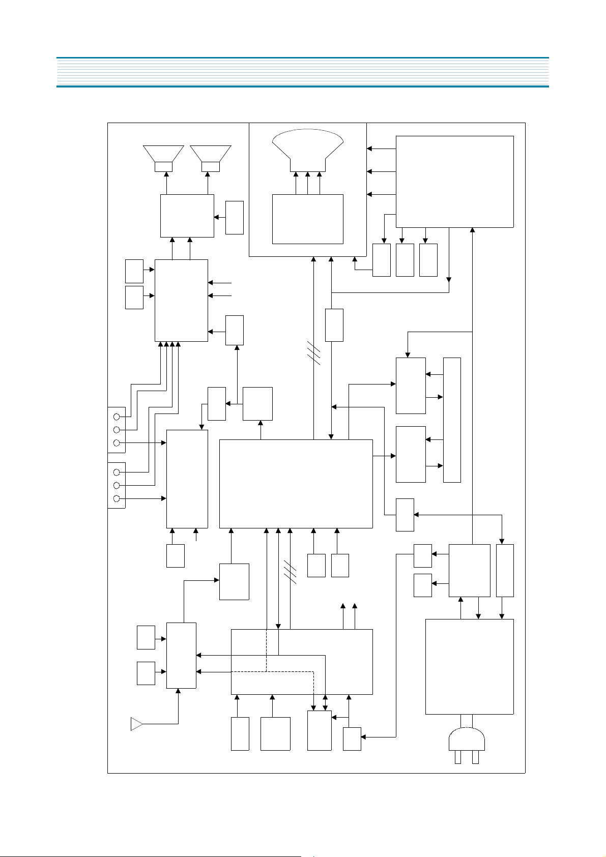
CIRCUIT BLOCK DIAGRAM
FBT Scr een Fouse H.V .
HEATER
SOUND
AMP
TDA7267
14V
A
MP
A
VIDEO
TDA6103Q
10V
200V
27V
FBT
DA
9V 5V
SCL S
SOUND IC
MSP3435G
BPF
IF DET.
TRAP
OUT
X-RAY
HOR. OUTPUT
2SD2578
IC
A7347P
VIDEO S/W IC
T
SCL
MAIN
A/V IN 1 A/V IN 2(29 ONLY)
DCT814B
SDA
RGB
VERTICAL
LA7845
DEFLECTION YOKE
OCP
9V
SAW
FILTER
DA
S
CONTROL
5V 33V
T UNER DT5-NF20F
RF
CL
S
IR
SW1 ~
SW5
(1) (2)
5V
9V
IC
(1)
SCL
u-COM
SDA
LC863240V
OSD RGB
EEPROM
(2)
SOUND SCL
SOUND SDA
5V
14V
SMPS TRANS
26V
POWER IC
TSM-4242B5
STR-F6626
HYBRID IC
5
Page 7
ALIGNMENT INSTRUCTIONS
1. SERVICE MODE ADJUSTMENTS
Follow the steps below whenever service adjustment is required. See Table- A and Table- B to determine if
service adjustments are required.
1) How to enter the service mode using the user remote control.
•
Turn the set on.
•
Direct the remote control to the reception window of TV.
•
Push buttons of remote control in sequence as follows.
1 → MUTE → DISPLAY → MUTE
•
Then, the screen will appear as follows.
S2 SCRN
S5 IFC
S6 GEO
S8 W/B
S9 DP
S12 FACT
S7 PTRN NORMAL
•
Using the channel up or channel down button, select the item you wish to adjust.
(The color of selected item turns into the red.)
•
Press the volume up or down button to enter in the service mode you wish to adjust.
2) How to memorize the adjusted values in the service mode.
•
Must press
DISPLAY
button the state which the screen is displaying each of service
after all adjustments are completed each of all service menu.
Table-A : Adjust the values of service mode when a part is replaced.
PART
REPLACED
I701
(U-COM)
I101
(MAIN)
I703
(EEPROM)
NECESSARY UNNECESSARY
ADJUSTMENT
O
O
O
Data is stored in I703.
Initial setting values are written from I701.
Adjusting Items
S5 RFAGCD
S6 H.PHASE/V.POSI/V.SIZE
S8 RD/BD/RB/GB/BB
S9 Subbrightness
menus
NOTES
CRT O Adjust items related to picture tube only.(White Balance adjustment)
6
Page 8
ALIGNMENT INSTRUCTIONS
Table-B
MODE ADJUSTMENT ITEMS
S2 Screen Adjustment - -
Auto RF AGC - Video Level (VIDEOL) 7 0 ~ 7 Must be set to 7
RF AGC Delay (RFAGCD) * 0 ~ 63 Align RF AGC threshold
S5
S6
S7
S8
S9
S12 Forwarding Mode - Factory Initialization
FM Level (FM.LEV) 8 0 ~ 31 Must be set to 20
AGC Point 3.75 - Select AGC reference voltage
A/D VALUE - Horizontal Phase(H.PHASE) * 0 ~ 31 Align sync to flyback pulse, using internal cross pattern(S7)
Vertical Position (V.POSI) * 0 ~ 63 Align vertical DC bias, using internal cross pattern(S7)
Vertical Size (V.SIZE) * 0 ~ 127 Align vertical amplitude, using internal cross pattern(S7)
NO SD POWER OFF YES - Automatically turn off in 15min for no received signal.
Vertical S-Correction (V SC) 0 0 ~ 31 Must be set to 6
Vertical Linearity (V LIN) 20 0 ~ 31 Must be set to 16
Internal Black - - Display internal BLACK pattern
Internal 100% White - - Display internal 100% WHITE
Internal 60% White - - Display internal 60% WHITE
Internal Cross Pattern - - Display internal CROSS pattern
Red Drive (RD) * 0 ~ 127 Align RED OUT AC level
Green Drive (GD) 10 0 ~ 15 Must be set to 10
Blue Drive (BD) * 0 ~ 127 Align BLUE OUT AC level
Red Bias (RB) * 0 ~ 255 Align RED OUT DC level
Green Bias (GB) * 0 ~ 255 Align GREEN OUT DC level
Blue Bias (BB) * 0 ~ 255 Align BLUE OUT DC level
Subbrightness * 0 ~ 127 Align common RGB DC level
Contrast 10 0 ~ 27
Tint 27 0 ~ 27
Color 15 0 ~ 27
DATA
INITIAL RANGE
REMARKS
*
indicates the items with different settings each of sets
2. ASSEMBLY ADJUSTMENTS
1) SCREEN ADJUSTMENT (S2)
•
Enter the service mode and select service adjustment S2.
•
You can see the one horizontal line on the screen.
•
Adjust the Screen Control Volume (located on FBT) so that the horizontal line onscreen may be
disappeared.
•
Press the volume up or down button to exit in the screen adjustment mode.
NOTE
IN THE SCREEN ADJUSTMENT MODE, DONT PRESS OTHER BUTTONS EXCEPT VOLUME UP OR DOWN BUTTON.
7
Page 9
2) FOCUS ADJUSTMENT
•
Turn in a local station and adjust the Focus Control knob (located on FBT) for best picture
details at high light condition.
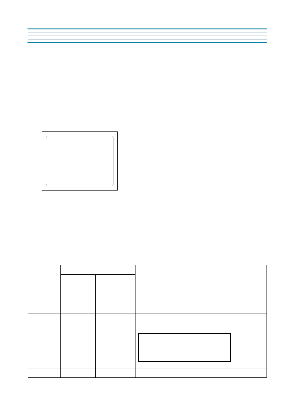
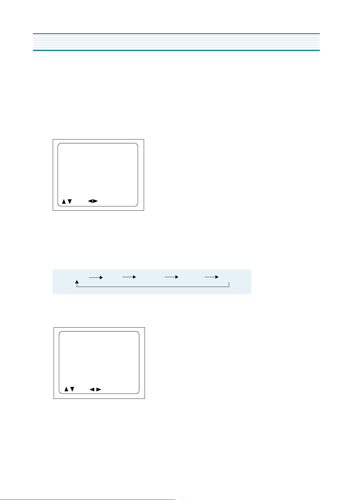
3) RF AGC DELAY ADJUSTMENT (S5)
•
Receive a good local channel.
•
Enter the service mode and select service adjustment S5.
•
You can see the OSD as shown in below.
IF CONTROL
AUTO RFAGC START
VIDEOL 7
RFAGCD 10
FM.LEV 8
AGC POINT 3.75
A/D VALUE : 8DH
MOVE ADJUST RECALL : SET
ALIGNMENT INSTRUCTIONS
•
Select RFAGCD item, press the volume up or down button until noise or beat in picture disappears.
•
Press the DISPLAY button to memorize the data.
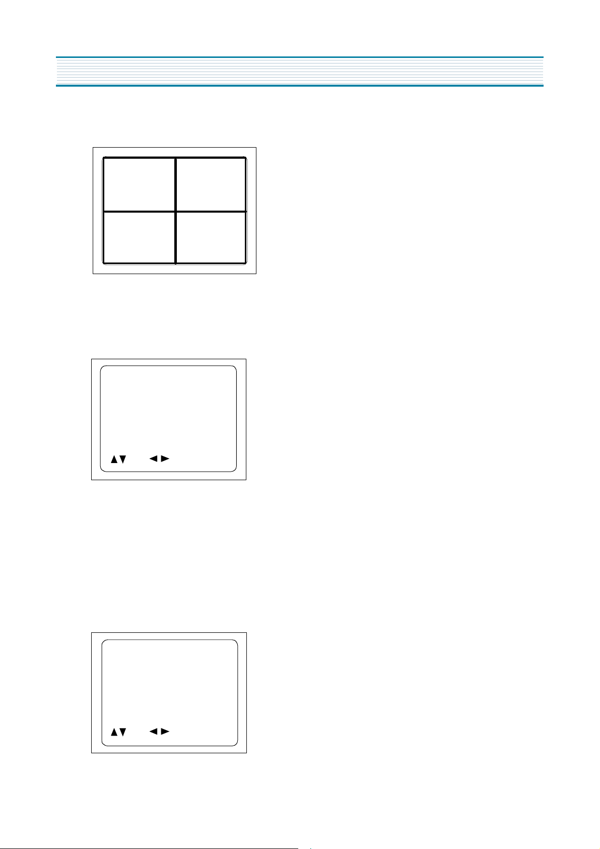
4) GEOMETRIC ADJUSTMENTS (S6)
•
Enter the service mode and select service adjustment S7.
•
Whenever you select the “S7” using the volume up or down button, the screen is changing like this.
NORMAL BLACK WHITE100 WHITE60 CROSS
•
Using the volume up or down button, select internal cross pattern.
•
Select service adjustment S6
•
You can see the OSD as shown in below.
GEOMETRY
H.PHASE20
V.POSI 29
V.SIZE 70
NO SD POWER OFF YES
VSC 0
VLIN 20
MOVE ADJUST RECALL : SET
4-1. Horizontal Position Adjustment
•
Select H.PHASE item, adjust H.PHASE data value to obtain proper horizontal centering of the
internal cross pattern at the left and right of the screen.
4-2. Vertical Position Adjustment
•
Select V.POSI item, adjust V.POSI data value to center the raster properly on thescreen.
8
Page 10
ALIGNMENT INSTRUCTIONS
4-3. Vertical Size Adjustment
•
Select “V.SIZE” item, adjust “V.SIZE” data value to proper vertical size as follows.
5) WHITE BALANCE ADJUSTMENT(S8)
•
Receive a good local channel.
•
Enter the service mode and select service adjustment S8.
•
You can see the OSD as shown in below.
RD 58
GD 10
BD 65
RB 105
GB 160
BB 100
MOVE ADJUST RECALL : SET
•
Using volume up or volume down, adjust service adjustment data of RD/GD/BD and RB/GB/BB until a good gray
scale with normal whites is obtained.ALIGNMENT INSTRUCTIONS
•
Press the DISPLAY button to memorize the data.
6) DIGITAL PRESET(D.P) ADJUSTMENTS(S9)
SUBBRIGHTNESS ADJUSTMENT
•
Receive a good local channel.
•
Enter the service mode and select service adjustment S9.
•
You can see the OSD as shown in below.
D.P.
SUB BRIGHTNESS 64
CONTRAST 27
TINT 27
COLOR 15
MOVE ADJUST RECALL : SET
9
Page 11

•
Select Subbrightness item, adjust Subbrightness data value
•
Press the DISPLAY button to memorize the data.
CONTRAST
•
Fixed value = 27
TINT
•
Fixed value = 27
COLOR
•
Fixed value = 15
7) FACTORY OUTGOING MODE (S12 : FACT)
•
If you select the S12, then the set becomes factory outgoing status.
•
You can see the OSD “outgoing OK”
ALIGNMENT INSTRUCTIONS
to obtain normal
brightness level.
10
Page 12
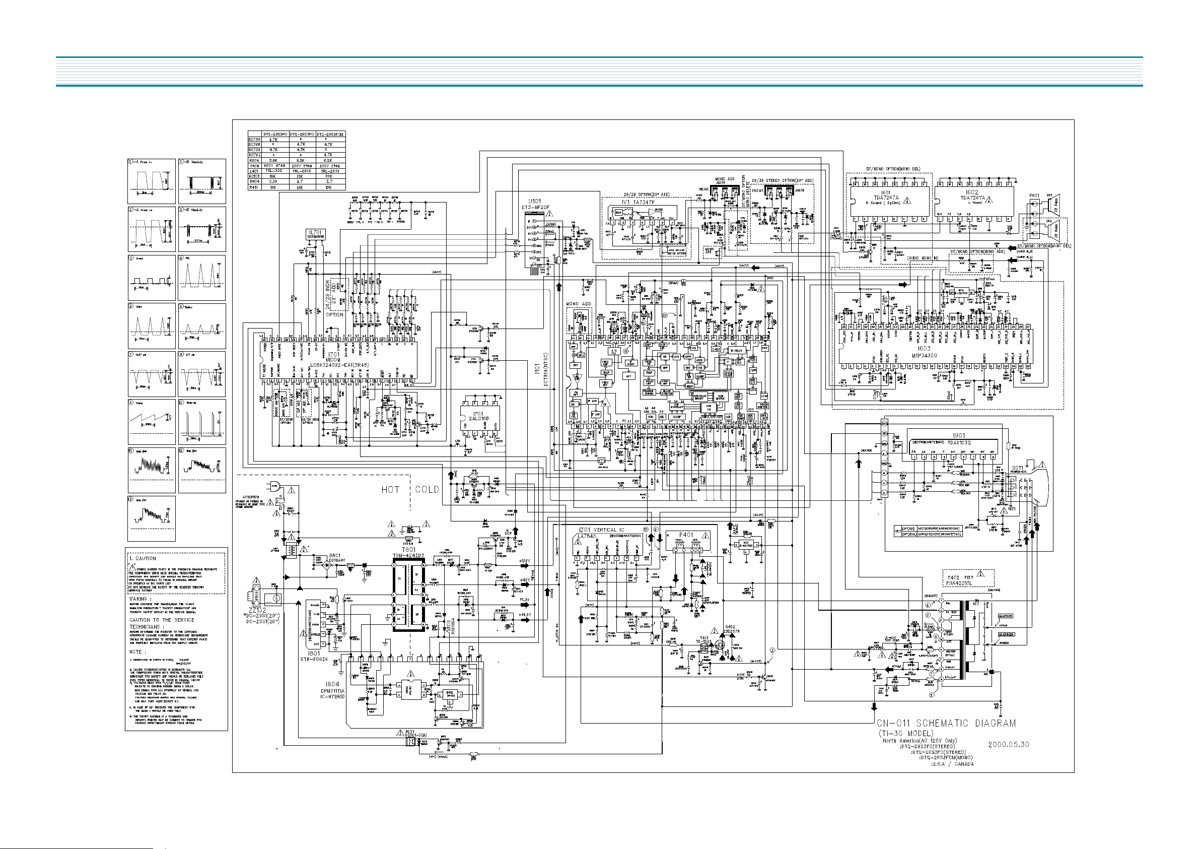
SCHEMATIC DIAGRAM
11
Page 13
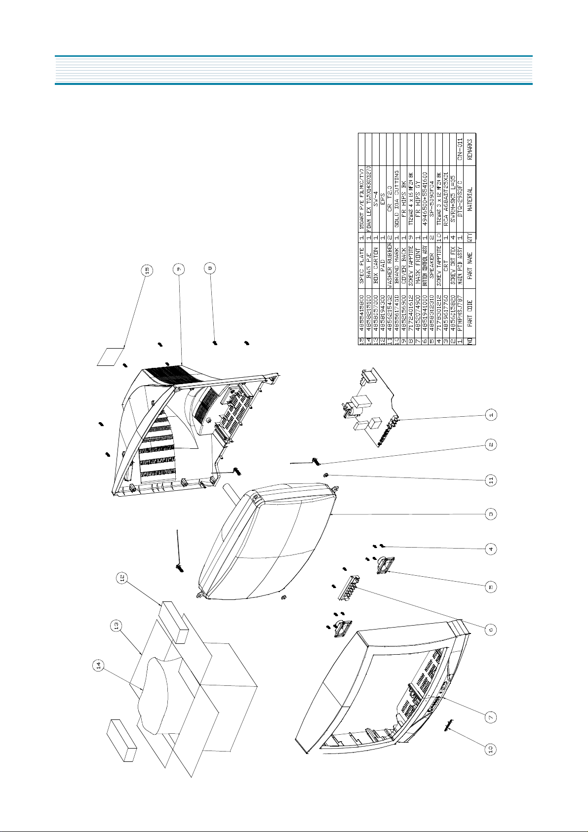
EXPLODED VIEW
1. DTQ-29S3FC
12
Page 14
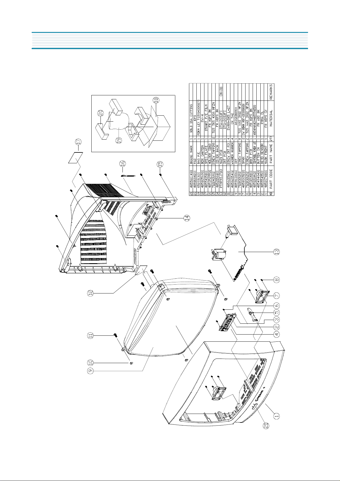
EXPLODED VIEW
2. DTQ-26S3FC
13
Page 15

3. DTQ-26S3FCM
EXPLODED VIEW
14
Page 16

PRINTED CIRCUIT BOARD
15
Page 17

SERVICE PARTS LIST
CAUTION
“I“ is a safety part, so it must be used the same part.
“ 2 ” is a recommendable part for stock.
LOC PART CODE PART NAME DESCRIPTION REMARK
DTQ-29S3FC DTQ-29S3FC
ZZ100 48B4343A01
ZZ110 PTACPWJ783 ACCESSORY AS DTQ-26S3FC
10 4850Q00810 BATTERY R6P/LN
20 48586054K1 MANUAL INSTRUCTION DTM-2082CW
M821 4858213800 BAG INSTRUCTION L.D.P.E T0.05X250X400
ZZ120 PTBCSHJ787 COVER BACK AS DTQ-29S3FC
M211 4852156900 COVER BACK FR HIPS BK
ZZ130 PTPKCPJ787 PACKING AS DTQ-29S3FC
M681 4856812400 BAND 18MM X 3M
M801 4858057000 BOX CARTON SW-4
M811 4858194300 PAD EPS
M821 4858215600 BAG P.E PE FOAM t0.5x1600x1270
ZZ131 58G0000143 COIL DEGAUSSING DC-29S1
ZZ132 48519A6210 CRT GROUND AS GND LINE IEA 29 I
ZZ140 PTCACAJ787 CABINET AS DTQ-29S3FC
M191 4851941000 BUTTON CTRL 4854946501+485541600
M191A 7178301212 SCREW TAPPTITE TT2 WAS 3X12 MFZN BK
M201B 4855800016 LABEL WARNING ART 300 92X20
M201C 4855622700 MARK BRAND SILVER DIA-CUTTING
M211A 7172401612 SCREW TAPPTITE TT2 TRS 4X16 MFZN BK
M211B 4855800013 LABEL MAKER ART 150 35X10
M541 4855415800 SPEC PLATE 150ART P/E FILM (C/TV)
SP01A 7178301212 SCREW TAPPTITE TT2 WAS 3X12 MFZN BK
SP01B 7178301212 SCREW TAPPTITE TT2 WAS 3X12 MFZN BK
V901 4859617760 CRT A68ADT25X01
V901A 4856015820 SCREW CRT FIX SWRM+SK5 L=35
V901B 4856215402 WASHER RUBBER CR T2.0
ZZ200 PTFMSJJ787 MASK FRONT AS DTQ-29S3FC
M201 4852074900 MASK FRONT FR HIPS GY
M201A 4857817610 CLOTH BLACK FELT 300X20X0.7
ZZ210 PTSPPWJ787 SPEAKER AS DTQ-29S3FC
P401A 4850704S35 CONNECTOR YFH800-04+YDT236+ULW=500
P601A 4850704S38 CONNECTOR YH025-04+35098+ULW=400
SP1 4858305220 SPEAKER 3W 8 OHM MSF-2D30SB02U
SP2 4858305220 SPEAKER 3W 8 OHM MSF-2D30SB02U
ZZ290 PTMPMSJ787
C310 CEYF1E332V C ELECTRO 25V RSS 3300MF (16X31.5)
C404 CMYH3C123J C MYLAR 1.6KV BUP 0.012MF J 2 I
C406 CMYE2G474J C MYLAR 400V PU 0.47MF J 2
C801 CL1JB3104M C LINE ACROSS AC250V 0.1MF M ECQ-UV WRL 2 I
C804 CEYD2D331D C ELECTRO 200V FHS330MF 22X30 25X31
C807 CH1BEE222M C CERA AC U/C/V 2.5KV 2200PF TP 2 I
C809 CBYB3D152K C CERA SEMI 2KV BL(N) 1500PF K 2
C812 CEYF1E332V C ELECTRO 25V RSS 3300MF (16X31.5)
TRANSMITTER REMOCON
PCB MAIN MANUAL AS
R-43A01 (AA) 2
DTQ-29S3FC
LOC PART CODE PART NAME DESCRIPTION REMARK
C814 CEYN2D221T C ELECTRO 200V FWS 220MF (22X30)
C825 CCXB3A471K C CERA 1KV B 470PF K (T)
C826 CEYF1E332V C ELECTRO 25V RSS 3300MF (16X31.5)
D801 DD5SBA60-- DIODE BRIDGE D5SBA60 2
D807 DBYT56K--- DIODE BYT56K
F801 5F1GB5021L FUSE GLASS TUBE CSA/UL 125V 5A 2 I
G901 4SG0D00103 SPARK GAP S-23 900V-1.5KV
G902 4SG0D00103 SPARK GAP S-23 900V-1.5KV
G903 4SG0D00103 SPARK GAP S-23 900V-1.5KV
I101 1DCT814B-- IC CHROMA DCT814B 2
I301 PTA2SW7921 HEAT SINK ASS 1LA7845N-- + 7174300811
I301 1LA7845N-- IC LA7845N 2 I
I301A 4857027921 HEAT SINK AL EX BK
I301B 7174300811 SCREW TAPPTITE TT2 RND 3X8 MFZN
I401 1K1A7805P1 IC REGULATOR KIA7805API
I601 1TDA7267A- IC AMP TDA7267A 2 I
I602 1TDA7267A- IC AMP TDA7267A 2 I
I603 1MSP3435G- IC SOUND MSP-3435G 2
I604 1K1A7805P1 IC REGULATOR KIA7805API 2
I701 1DW8632EA1 IC MICOM DW863240V-EA1(5R48) 2
I703 1AT24C16PC IC AT24C16-10PC 2
I801 PTF2SW7701 HEAT SINK ASS 1STRF6626- + 7174300811 2 I
I801 1STRF6626- IC POWER STR-F6626 2 I
I801A 4857027701 HEAT SINK AL EX
I801B 7174300811 SCREW TAPPTITE TT2 RND 3X8 MFZN
I803 TX0202DA-- THYRISTOR X0202DA1BA2 2
I804 4850M04810 MODULE POWER DPM011 TI 2 I
I901 PTG1SW8902 HEAT SINK ASS 1TDA6103Q- + 7174300811
I901 1TDA6103Q- IC VIDEO TDA6103Q 2
I901A 4857018902 HEAT SINK A1050P-H24
I901B 7174300811 SCREW TAPPTITE TT2 RND 3X8 MFZN
IL701 1KRT30---- IC PREAMP KRT30
IV1 1TA7347P-- IC SWITCH TA7347P 2
JA001 4859109250 JACK PIN BOARD PH-JB-9614A
JA002 4859108450 JACK PIN BOARD YSC03P-4120-14A
L111 58C5580019 COIL CHOKE TRF-9225 (0.55UH)
L401 58H0000025 COIL H-LINEARITY TRL-330
L501 58N0000042 COIL VCO TRF-V008
L605 58C0000090 COIL CHOKE L-45S
L801 5PLF24A1-- FILTER LINE LF-24A1 2 I
L805 58C4500079 COIL CHOKE L-45
MP01 4856813600 HOLDER WIRE NYLON 66 DAWH-13NA
P501 4850708N08 CONNECTOR BIC-08T-25T+C-20T+ULW=400
PWC1 4859907810 CORD POWER AS ME301P+TER=2100 2 I
Q401 TKTC3208-- TR KTC3208
16
Page 18

SERVICE PARTS LIST
LOC PART CODE PART NAME DESCRIPTION REMARK
Q402 PTB2SW7609 HEAT SINK ASS‘Y T2SD2578-- + 7174300811
Q402 T2SD2578-- TR 2SD2578 2 I
Q402A 4857027609 HEAT SINK AL EX
Q402B 7174300811 SCREW TAPPTITE TT2 RND 3X8 MFZN
Q802 TKTA968AY- TR KTA968AY
R801 RX10B109JN R CEMENT 10W 1 OHM J BENCH 4P
R805 RW02Z128KS R WIRE WOUND 2W 0.12 OHM K SMALL 2
R806 DPB3R0M140 POSISTOR 2322 662 96693 2
RLY1 5SC0101338 SW RELAY DQ5D1-O(M)/GJ-SS-105LM 2 I
RS801 DSVC471D14 VARISTOR SVC471D14A 2 I
SCT1 4859303830 SOCKET CRT ISHG94S
SF101 5PTSF5241P FILTER SAW TSF5241P
T401 50D15A1--- TRANS DRIVE TD-15A1 2
T402 50H0000208 FBT FSA42013L 2 I
T801 50M4242B5- TRANS SMPS TSM-4242B5
U101 4859719130 TUNER VARACTOR DT5-NF20F 2 I
X601 5XE18R432E CRYSTAL QUARTZ HC-49/U 18.43200MHZ 30PPM
X701 5XYR03276C CRYSTAL QUARTZ C-001R 32.768000KHZ 20PPM
Z501 5PXPS45MB- FILTER CERA TPS-4.5MB TRAP (TAPPING)
ZZ200 PTMPJ2J787 PCB CHIP MOUNT B AS DTQ-29S3FC
CC151 HCFK104ZCA C CHIP CERA 50V Y5V 0.1MF Z 2012
CC152 HCFK104ZCA C CHIP CERA 50V Y5V 0.1MF Z 2012
CC153 HCFK104ZCA C CHIP CERA 50V Y5V 0.1MF Z 2012
CC154 HCFK104ZCA C CHIP CERA 50V Y5V 0.1MF Z 2012
CC155 HCFK103ZCA C CHIP CERA 50V Y5V 0.01MF Z 2012
CC201 HCFK104ZCA C CHIP CERA 50V Y5V 0.1MF Z 2012
CC202 HCQK820JCA C CHIP CERA 50V CH 82PF J 2012
CC203 HCFK104ZCA C CHIP CERA 50V Y5V 0.1MF Z 2012
CC528 HCBK102KCA C CHIP CERA 50V X7R 1000PF K 2012
CC530 HCFK104ZCA C CHIP CERA 50V Y5V 0.1MF Z 2012
CC551 HCQK101JCA C CHIP CERA 50V CH 100PF J 2012
CC552 HCQK101JCA C CHIP CERA 50V CH 100PF J 2012
CC560 HCFK104ZCA C CHIP CERA 50V Y5V 0.1MF Z 2012
CC562 HCQK180JCA C CHIP CERA 50V CH 18PF J 2012
CC567 HCQK181JCA C CHIP CERA 50V CH 180PF J 2012
CC568 HCFK104ZCA C CHIP CERA 50V Y5V 0.1MF Z 2012
CC571 HCFK104ZCA C CHIP CERA 50V Y5V 0.1MF Z 2012
CC573 HCFK104ZCA C CHIP CERA 50V Y5V 0.1MF Z 2012
CC575 HCQK102JCA C CHIP CERA 50V CH 1000PF J 2012
CC601 HCQK471JCA C CHIP CERA 50V CH 470PF J 2012
CC602 HCQK471JCA C CHIP CERA 50V CH 470PF J 2012
CC603 HCQK561JCA C CHIP CERA 50V CH 560PF J 2012
CC604 HCFK104ZCA C CHIP CERA 50V Y5V 0.1MF Z 2012
CC605 HCQK561JCA C CHIP CERA 50V CH 560PF J 2012
CC606 HCQK561JCA C CHIP CERA 50V CH 560PF J 2012
CC607 HCBK472KCA C CHIP CERA 50V X7R 4700PF K 2012
CC608 HCFK104ZCA C CHIP CERA 50V Y5V 0.1MF Z 2012
CC610 HCFK104ZCA C CHIP CERA 50V Y5V 0.1MF Z 2012
CC611 HCFK104ZCA C CHIP CERA 50V Y5V 0.1MF Z 2012
LOC PART CODE PART NAME DESCRIPTION REMARK
CC612 HCBK472KCA C CHIP CERA 50V X7R 4700PF K 2012
CC613 HCBK102KCA C CHIP CERA 50V X7R 1000PF K 2012
CC614 HCBK102KCA C CHIP CERA 50V X7R 1000PF K 2012
CC615 HCFK104ZCA C CHIP CERA 50V Y5V 0.1MF Z 2012
CC616 HCFK103ZCA C CHIP CERA 50V Y5V 0.01MF Z 2012
CC617 HCQK479CCA C CHIP CERA 50V CH 4.7PF C 2012
CC618 HCQK479CCA C CHIP CERA 50V CH 4.7PF C 2012
CC619 HCFK104ZCA C CHIP CERA 50V Y5V 0.1MF Z 2012
CC620 HCFK104ZCA C CHIP CERA 50V Y5V 0.1MF Z 2012
CC621 HCBK471KCA C CHIP CERA 50V X7R 470PF K 2012
CC622 HCBK471KCA C CHIP CERA 50V X7R 470PF K 2012
CC623 HCBK471KCA C CHIP CERA 50V X7R 470PF K 2012
CC624 HCBK471KCA C CHIP CERA 50V X7R 470PF K 2012
CC625 HCFK104ZCA C CHIP CERA 50V Y5V 0.1MF Z 2012
CC626 HCFK103ZCA C CHIP CERA 50V Y5V 0.01MF Z 2012
CC627 HCFK104ZCA C CHIP CERA 50V Y5V 0.1MF Z 2012
CC628 HCFK104ZCA C CHIP CERA 50V Y5V 0.1MF Z 2012
CC630 HCFK103ZCA C CHIP CERA 50V Y5V 0.01MF Z 2012
CC631 HCQK470JCA C CHIP CERA 50V CH 47PF J 2012
CC632 HCQK200JCA C CHIP CERA 50V CH 20PF J 2012
CC708 HCQK120JCA C CHIP CERA 50V CH 12PF J 2012
CC711 HCQK221JCA C CHIP CERA 50V CH 220PF J 2012
CC713 HCQK101JCA C CHIP CERA 50V CH 100PF J 2012
CC714 HCQK101JCA C CHIP CERA 50V CH 100PF J 2012
CC715 HCQK101JCA C CHIP CERA 50V CH 100PF J 2012
CC717 HCQK101JCA C CHIP CERA 50V CH 100PF J 2012
CC719 HCFK104ZCA C CHIP CERA 50V Y5V 0.1MF Z 2012
CC752 HCQK180JCA C CHIP CERA 50V CH 18PF J 2012
CC754 HCFK104ZCA C CHIP CERA 50V Y5V 0.1MF Z 2012
CC755 HCFK103ZCA C CHIP CERA 50V Y5V 0.01MF Z 2012
CC757 HCBK333KCA C CHIP CERA 50V X7R 0.033MF K 2012
CC777 HCFK103ZCA C CHIP CERA 50V Y5V 0.01MF Z 2012
CC821 HCFK104ZCA C CHIP CERA 50V Y5V 0.1MF Z 2012
JC001 HRFT000-CA R CHIP 1/10 0 OHM 2012
JC004 HRFT000-CA R CHIP 1/10 0 OHM 2012
JC005 HRFT000-CA R CHIP 1/10 0 OHM 2012
JC007 HRFT000-CA R CHIP 1/10 0 OHM 2012
RC105 HRFT153JCA R CHIP 1/10 15K OHM J 2012
RC150 HRFT153JCA R CHIP 1/10 15K OHM J 2012
RC151 HRFT104JCA R CHIP 1/10 100K OHM J 2012
RC154 HRFT473JCA R CHIP 1/10 47K OHM J 2012
RC156 HRFT473JCA R CHIP 1/10 47K OHM J 2012
RC201 HRFT101JCA R CHIP 1/10 100 OHM J 2012
RC206 HRFT101JCA R CHIP 1/10 100 OHM J 2012
RC208 HRFT512JCA R CHIP 1/10 5.1K OHM J 2012
RC212 HRFT750JCA R CHIP 1/10 75 OHM J 2012
RC351 HRFT472JCA R CHIP 1/10 4.7K OHM J 2012
RC359 HRFT623JCA R CHIP 1/10 62K OHM J 2012
RC360 HRFT562JCA R CHIP 1/10 5.6K OHM J 2012
17
Page 19

SERVICE PARTS LIST
LOC PART CODE PART NAME DESCRIPTION REMARK
RC361 HRFT113JCA R CHIP 1/10 11K OHM J 2012
RC362 HRFT473JCA R CHIP 1/10 47K OHM J 2012
RC412 HRFT102JCA R CHIP 1/10 1K OHM J 2012
RC502 HRFT331JCA R CHIP 1/10 330 OHM J 2012
RC503 HRFT331JCA R CHIP 1/10 330 OHM J 2012
RC504 HRFT824JCA R CHIP 1/10 820K OHM J 2012
RC505 HRFT331JCA R CHIP 1/10 330 OHM J 2012
RC508 HRFT102JCA R CHIP 1/10 1K OHM J 2012
RC509 HRFT102JCA R CHIP 1/10 1K OHM J 2012
RC510 HRFT561JCA R CHIP 1/10 560 OHM J 2012
RC525 HRFT102JCA R CHIP 1/10 1K OHM J 2012
RC526 HRFT132JCA R CHIP 1/10 1.3K OHM J 2012
RC530 HRFT561JCA R CHIP 1/10 560 OHM J 2012
RC531 HRFT821JCA R CHIP 1/10 820 OHM J 2012
RC533 HRFT390JCA R CHIP 1/10 39 OHM J 2012
RC557 HRFT182JCA R CHIP 1/10 1.8K OHM J 2012
RC559 HRFT331JCA R CHIP 1/10 330 OHM J 2012
RC560 HRFT103JCA R CHIP 1/10 10K OHM J 2012
RC561 HRFT561JCA R CHIP 1/10 560 OHM J 2012
RC562 HRFT914JCA R CHIP 1/10 910KOHM J 2012
RC565 HRFT123JCA R CHIP 1/10 12K OHM J 2012
RC566 HRFT123JCA R CHIP 1/10 12K OHM J 2012
RC567 HRFT103JCA R CHIP 1/10 10K OHM J 2012
RC568 HRFT472JCA R CHIP 1/10 4.7K OHM J 2012
RC569 HRFT152JCA R CHIP 1/10 1.5K OHM J 2012
RC570 HRFT103JCA R CHIP 1/10 10K OHM J 2012
RC571 HRFT272JCA R CHIP 1/10 2.7K OHM J 2012
RC572 HRFT223JCA R CHIP 1/10 22K OHM J 2012
RC573 HRFT102JCA R CHIP 1/10 1K OHM J 2012
RC601 HRFT182JCA R CHIP 1/10 1.8K OHM J 2012
RC602 HRFT182JCA R CHIP 1/10 1.8K OHM J 2012
RC603 HRFT102JCA R CHIP 1/10 1K OHM J 2012
RC604 HRFT473JCA R CHIP 1/10 47K OHM J 2012
RC605 HRFT392JCA R CHIP 1/10 3.9K OHM J 2012
RC606 HRFT102JCA R CHIP 1/10 1K OHM J 2012
RC608 HRFT102JCA R CHIP 1/10 1K OHM J 2012
RC610 HRFT102JCA R CHIP 1/10 1K OHM J 2012
RC611 HRFT102JCA R CHIP 1/10 1K OHM J 2012
RC612 HRFT102JCA R CHIP 1/10 1K OHM J 2012
RC613 HRFT473JCA R CHIP 1/10 47K OHM J 2012
RC614 HRFT473JCA R CHIP 1/10 47K OHM J 2012
RC615 HRFT102JCA R CHIP 1/10 1K OHM J 2012
RC616 HRFT473JCA R CHIP 1/10 47K OHM J 2012
RC618 HRFT472JCA R CHIP 1/10 4.7K OHM J 2012
RC703 HRFT473JCA R CHIP 1/10 47K OHM J 2012
RC704 HRFT471JCA R CHIP 1/10 470 OHM J 2012
RC705 HRFT471JCA R CHIP 1/10 470 OHM J 2012
RC706 HRFT101JCA R CHIP 1/10 100 OHM J 2012
RC707 HRFT101JCA R CHIP 1/10 100 OHM J 2012
LOC PART CODE PART NAME DESCRIPTION REMARK
RC708 HRFT472JCA R CHIP 1/10 4.7K OHM J 2012
RC712 HRFT472JCA R CHIP 1/10 4.7K OHM J 2012
RC713 HRFT102JCA R CHIP 1/10 1K OHM J 2012
RC714 HRFT102JCA R CHIP 1/10 1K OHM J 2012
RC715 HRFT103JCA R CHIP 1/10 10K OHM J 2012
RC716 HRFT472JCA R CHIP 1/10 4.7K OHM J 2012
RC717 HRFT103JCA R CHIP 1/10 10K OHM J 2012
RC720 HRFT101JCA R CHIP 1/10 100 OHM J 2012
RC721 HRFT471JCA R CHIP 1/10 470 OHM J 2012
RC722 HRFT512JCA R CHIP 1/10 5.1K OHM J 2012
RC723 HRFT103JCA R CHIP 1/10 10K OHM J 2012
RC725 HRFT103JCA R CHIP 1/10 10K OHM J 2012
RC726 HRFT471JCA R CHIP 1/10 470 OHM J 2012
RC727 HRFT103JCA R CHIP 1/10 10K OHM J 2012
RC728 HRFT102JCA R CHIP 1/10 1K OHM J 2012
RC732 HRFT102JCA R CHIP 1/10 1K OHM J 2012
RC733 HRFT102JCA R CHIP 1/10 1K OHM J 2012
RC734 HRFT102JCA R CHIP 1/10 1K OHM J 2012
RC735 HRFT102JCA R CHIP 1/10 1K OHM J 2012
RC736 HRFT392JCA R CHIP 1/10 3.9K OHM J 2012
RC737 HRFT102JCA R CHIP 1/10 1K OHM J 2012
RC738 HRFT102JCA R CHIP 1/10 1K OHM J 2012
RC739 HRFT102JCA R CHIP 1/10 1K OHM J 2012
RC741 HRFT103JCA R CHIP 1/10 10K OHM J 2012
RC742 HRFT101JCA R CHIP 1/10 100 OHM J 2012
RC743 HRFT472JCA R CHIP 1/10 4.7K OHM J 2012
RC744 HRFT102JCA R CHIP 1/10 1K OHM J 2012
RC745 HRFT152JCA R CHIP 1/10 1.5K OHM J 2012
RC746 HRFT222JCA R CHIP 1/10 2.2K OHM J 2012
RC747 HRFT392JCA R CHIP 1/10 3.9K OHM J 2012
RC748 HRFT102JCA R CHIP 1/10 1K OHM J 2012
RC749 HRFT103JCA R CHIP 1/10 10K OHM J 2012
RC755 HRFT472JCA R CHIP 1/10 4.7K OHM J 2012
RC756 HRFT472JCA R CHIP 1/10 4.7K OHM J 2012
RC758 HRFT472JCA R CHIP 1/10 4.7K OHM J 2012
RC759 HRFT472JCA R CHIP 1/10 4.7K OHM J 2012
RC767 HRFT472JCA R CHIP 1/10 4.7K OHM J 2012
RC770 HRFT472JCA R CHIP 1/10 4.7K OHM J 2012
RC776 HRFT103JCA R CHIP 1/10 10K OHM J 2012
RC777 HRFT103JCA R CHIP 1/10 10K OHM J 2012
RC781 HRFT101JCA R CHIP 1/10 100 OHM J 2012
RC782 HRFT331JCA R CHIP 1/10 330 OHM J 2012
RC784 HRFT514JCA R CHIP 1/10 510K OHM J 2012
RC785 HRFT102JCA R CHIP 1/10 1K OHM J 2012
RC790 HRFT472JCA R CHIP 1/10 4.7K OHM J 2012
RC799 HRFT103JCA R CHIP 1/10 10K OHM J 2012
RC801 HRFT911JCA R CHIP 1/10 910 OHM J 2012
RC802 HRFT472JCA R CHIP 1/10 4.7K OHM J 2012
RC803 HRFT473JCA R CHIP 1/10 47K OHM J 2012
18
Page 20

SERVICE PARTS LIST
LOC PART CODE PART NAME DESCRIPTION REMARK
RC901 HRFT302JCA R CHIP 1/10 3K OHM J 2012
RC902 HRFT302JCA R CHIP 1/10 3K OHM J 2012
RC903 HRFT302JCA R CHIP 1/10 3K OHM J 2012
RC904 HRFT222JCA R CHIP 1/10 2.2K OHM J 2012
RC905 HRFT222JCA R CHIP 1/10 2.2K OHM J 2012
RC906 HRFT222JCA R CHIP 1/10 2.2K OHM J 2012
RC908 HRFT472FCA R CHIP 1/10 4.7K OHM F 2012
ZZ200 PTMPJ0J787 PCB MAIN (RHU) AS DTQ-29S3FC
C105 CEXF1C471V C ELECTRO 16V RSS 470MF (10X12.5)TP
C401 CCXB2H472K C CERA 500V B 4700PF K (TAPPING)
C405 CEXA2D229E C ELECTRO 200V RUL 2.2MF (10X16) TP
C410 CEXF2E470V C ELECTRO
C414 CEXF1V471V C ELECTRO
C415 CEXF1C102V C ELECTRO 16V RSS 1000MF (10X20) TP
C504 CEXF1C471V C ELECTRO 16V RSS 470MF (10X12.5)TP
C514 CEXF1C471V C ELECTRO 16V RSS 470MF (10X12.5)TP
C602 CEXF1C471V C ELECTRO 16V RSS 470MF (10X12.5)TP
C605 CEXF1C471V C ELECTRO
C608 CEXF1C471V C ELECTRO
C815 CEXF2A470V C ELECTRO 100V RSS 47MF (10X16) TP
C823 CCXB3D681K C CERA 2KV B 680PF K (TAPPING)
C824 CEXE2C100H C ELECTRO 160V RUR 10MF (13X25) TP
C901 CEXF2E100V C ELECTRO 250V RSS 10MF (10X20) TP
C902 CH1BEE472M C CERA AC U/C/V 2.5KV 4700PF TP
ZZ200 PTMPJBJ787 PCB MAIN M-10 AS DTQ-29S3FC
P401A 4857417500 TERM PIN DA-IB0214(D2.3/DY PIN)
P401B 4857417500 TERM PIN DA-IB0214(D2.3/DY PIN)
P401C 4857417500 TERM PIN DA-IB0214(D2.3/DY PIN)
P401D 4857417500 TERM PIN DA-IB0214(D2.3/DY PIN)
P601 485923172S CONN WAFER YW025-04 (STICK)
P801A 4857417500 TERM PIN DA-IB0214(D2.3/DY PIN)
P801B 4857417500 TERM PIN DA-IB0214(D2.3/DY PIN)
R104 RS01Z472J- R M-OXIDE FILM 1W 4.7K OHM J (TAPPING)
R401 RF01Z229J- R FUSIBLE 1W 2.2 OHM J (TAPPING)
R404 RF01Z398K- R FUSIBLE 1W 0.39 OHM K (TAPPING)
R814 RF01Z398K- R FUSIBLE 1W 0.39 OHM K (TAPPING)
ZZ200 PTMPJRJ787 PCB MAIN RADIAL AS DTQ-29S3FC
C101 CEXF1H100V C ELECTRO 50V RSS 10MF (5X11) TP
C102 CEXF1C101V C ELECTRO 16V RSS 100MF (6.3X11) TP
C103 CEXF1H229V C ELECTRO 50V RSS 2.2MF (5X11) TP
C104 CMXB1H333J C MYLAR 50V EU 0.033MF J (TP)
C106 CEXF1H109V C ELECTRO 50V RSS 1MF (5X11) TP
C107 CEXF1H228V C ELECTRO 50V RSS 0.22MF (5X11) TP
C202 CEXD1H479F C ELECTRO 50V RND 4.7MF (6.3X11) TP
C203 CEXF1H479V C ELECTRO 50V RSS 4.7MF (5X11) TP
C204 CEXF1H479V C ELECTRO 50V RSS 4.7MF (5X11) TP
C205 CEXF1E221V C ELECTRO
C301 CMXB1H103J C MYLAR 50V EU 0.01MF J (TP)
C302 CEXF1H479V C ELECTRO 50V RSS 4.7MF (5X11) TP
250V RSS 47MF (16X25) TP
35V RSS 470MF (10X20) TP
16V RSS 470MF (10X12.5)TP
16V RSS 470MF (10X12.5)TP
R
R
R
25V RSS 220MF (8X11.5) TP
LOC PART CODE PART NAME DESCRIPTION REMARK
C303 CEXF1H100V C ELECTRO 50V RSS 10MF (5X11) TP
C304 CMXB1H224J C MYLAR 50V EU 0.22MF J (TP)
C305 CEXF1H101V C ELECTRO 50V RSS 100MF (8X11.5) TP
C307 CXSL2H100D C CERA 500V SL 10PF D (TAPPING)
C308 CMXB1H473J C MYLAR 50V 0.047MF J (TP)
C309 CEXD1H109Q C ELECTRO 50V RT 1MF (6.3X11) TP
C311 CEXD1H109Q C ELECTRO 50V RT 1MF (6.3X11) TP
C402 CEXF1C221V C ELECTRO 16V RSS 220MF (8X11.5) TP
C403 CEXF1H109V C ELECTRO 50V RSS 1MF (5X11) TP
C408 CEXF1H470V C ELECTRO 50V RSS 47MF (6.3X11) TP
C409 CEXF1C101V C ELECTRO 16V RSS 100MF (6.3X11) TP
C411 CEXF1H470V C ELECTRO
C412 CCXB2H102K C CERA
C413 CCXB2H102K C CERA 500V B 1000PF K (TAPPING)
C416 CCXB2H102K C CERA 500V B 1000PF K (TAPPING)
C417 CCXB2H102K C CERA 500V B 1000PF K (TAPPING)
C418 CMXB1H104J C MYLAR 50V EU 0.1MF J (TP)
C501 CMXL1H105J C MYLAR
C502 CEXF1C221V C ELECTRO
C503 CEXF1H109V C ELECTRO 50V RSS 1MF (5X11) TP
C505 CEXF1H100V C ELECTRO 50V RSS 10MF (5X11) TP
C506 CEXF1H109V C ELECTRO 50V RSS 1MF (5X11) TP
C507 CMXB1H224J C MYLAR 50V EU 0.22MF J (TP)
C508 CMXB1H224J C MYLAR 50V EU 0.22MF J (TP)
C509 CEXF1H109V C ELECTRO 50V RSS 1MF (5X11) TP
C511 CMXB1H333J C MYLAR 50V EU 0.033MF J (TP)
C512 CEXF1H108V C ELECTRO 50V RSS 0.1MF (5X11) TP
C513 CEXF1H109V C ELECTRO 50V RSS 1MF (5X11) TP
C515 CEXF1H478V C ELECTRO 50V RSS 0.47MF (5X11) TP
C516 CEXF1H229V C ELECTRO 50V RSS 2.2MF (5X11) TP
C517 CMXB1H473J C MYLAR 50V 0.047MF J (TP)
C518 CEXF1H478V C ELECTRO 50V RSS 0.47MF (5X11) TP
C555 CEXF1H109V C ELECTRO 50V RSS 1MF (5X11) TP
C603 CEXF1H108V C ELECTRO 50V RSS 0.1MF (5X11) TP
C604 CEXF1H470V C ELECTRO 50V RSS 47MF (6.3X11) TP
C606 CEXF1H108V C ELECTRO 50V RSS 0.1MF (5X11) TP
C607 CEXF1H101V C ELECTRO 50V RSS 100MF (8X11.5) TP
C609 CEXF1H479V C ELECTRO 50V RSS 4.7MF (5X11) TP
C610 CEXF1H479V C ELECTRO 50V RSS 4.7MF (5X11) TP
C611 CEXF1H479V C ELECTRO 50V RSS 4.7MF (5X11) TP
C612 CEXF1H479V C ELECTRO 50V RSS 4.7MF (5X11) TP
C613 CEXF1H100V C ELECTRO 50V RSS 10MF (5X11) TP
C614 CEXF1H100V C ELECTRO 50V RSS 10MF (5X11) TP
C615 CEXF1H470V C ELECTRO 50V RSS 47MF (6.3X11) TP
C616 CEXF1H100V C ELECTRO 50V RSS 10MF (5X11) TP
C618 CEXF1H100V C ELECTRO 50V RSS 10MF (5X11) TP
C619 CEXF1H100V C ELECTRO 50V RSS 10MF (5X11) TP
C620 CEXF1H100V C ELECTRO 50V RSS 10MF (5X11) TP
C621 CEXF1H339V C ELECTRO 50V RSS 3.3MF (5X11) TP
50V RSS 47MF (6.3X11) TP
500V B 1000PF K (TAPPING)
50V MEU 1MF J
16V RSS 220MF (8X11.5) TP
I
19
Page 21

SERVICE PARTS LIST
LOC PART CODE PART NAME DESCRIPTION REMARK
C622 CEXF1H100V C ELECTRO 50V RSS 10MF (5X11) TP
C623 CEXF1H470V C ELECTRO 50V RSS 47MF (6.3X11) TP
C624 CEXF1H470V C ELECTRO 50V RSS 47MF (6.3X11) TP
C626 CEXF1H229V C ELECTRO 50V RSS 2.2MF (5X11) TP
C701 CEXF1H470V C ELECTRO 50V RSS 47MF (6.3X11) TP
C703 CEXF1H109V C ELECTRO 50V RSS 1MF (5X11) TP
C704 CEXF1H229V C ELECTRO 50V RSS 2.2MF (5X11) TP
C705 CEXF1H109V C ELECTRO 50V RSS 1MF (5X11) TP
C709 CEXF1C221V C ELECTRO 16V RSS 220MF (8X11.5) TP
C802 CCXB2H222K C CERA 500V B 2200PF K (TAPPING)
C803 CCXB2H222K C CERA 500V B 2200PF K (TAPPING)
C806 CEXF1H470C C ELECTRO 50V RUS 47MF (6.3X11) TP
C810 CEXF1H479V C ELECTRO 50V RSS 4.7MF (5X11) TP
C811 CCXB3A471K C CERA 1KV B 470PF K (T)
C813 CCXB3A471K C CERA 1KV B 470PF K (T)
C816 CCXB3A471K C CERA 1KV B 470PF K (T)
C818 CEXF1H220C C ELECTRO 50V RUS 22MF (5X11) TP
C819 CEXF1H479V C ELECTRO 50V RSS 4.7MF (5X11) TP
C822 CEXF1C101A C ELECTRO
C832 CEXF1E101V C ELECTRO 25V RSS 100MF (6.3X11) TP
C903 CMXL1J224J C MYLAR 63V MEU 0.22MF J (TP)
C904 CMXL2E104K C MYLAR 250V MEU 0.1MF K
F801A 4857415001 CLIP FUSE PFC5000-0702
F801B 4857415001 CLIP FUSE PFC5000-0702
Q403 TKTC3198Y- TR KTC3198Y
Q601 TKTC3198Y- TR KTC3198Y
Q701 TKTC3198Y- TR KTC3198Y
Q702 TKTC3198Y- TR KTC3198Y
Q703 TKTC3198Y- TR KTC3198Y
Q704 TKSA733CY- TR KSA733CY (TP)
Q801 TKTC3198Y- TR KTC3198Y
Q805 TKTC3205Y- TR KTC3205Y (TP)
R301 RN02B202JS R METAL FILM 2W 2K OHM J SMALL
R302 RN01B331JS R METAL FILM 1W 330 OHM J SMALL
R303 RN01B109JS R METAL FILM 1W 1 OHM J SMALL
R304 RN01B109JS R METAL FILM 1W 1 OHM J SMALL
R305 RN02B271JS R METAL FILM 2W 270 OHM J SMALL
R402 RN02B102JS R METAL FILM 2W 1K OHM J SMALL
R403 RN02B103JS R METAL FILM 2W 10K OHM J SMALL
R405 RN02B181JS R METAL FILM 2W 180 OHM J SMALL
R407 RN02B229JS R METAL FILM 2W 2.2 OHM J SMALL
R408 RN02B229JS R METAL FILM 2W 2.2 OHM J SMALL
R419 RN02B101JS R METAL FILM 2W 100 OHM J SMALL
R420 RN02B620JS R METAL FILM 2W 62 OHM J SMALL
R501 RN02B151JS R METAL FILM 2W 150 OHM J SMALL
R604 RN01B750JS R METAL FILM 1W 75 OHM J SMALL
R605 RN01B121JS R METAL FILM 1W 120 OHM J SMALL
R802 RN02B273JS R METAL FILM 2W 27K OHM J SMALL
R809 RN01B121JS R METAL FILM 1W 120 OHM J SMALL
16V RSM 100MF (6.3X7) TP
LOC PART CODE PART NAME DESCRIPTION REMARK
R812 RN01B301JS R METAL FILM 1W 300 OHM J SMALL
R913 RN01B124JS R METAL FILM 1W 120K OHM J SMALL
R914 RN01B124JS R METAL FILM 1W 120K OHM J SMALL
R915 RN01B124JS R METAL FILM 1W 120K OHM J SMALL
R917 RN02B189JS R METAL FILM 2W 1.8 OHM J SMALL 2
SW701 5S50101090 SW TACT SKHV17910A
SW702 5S50101090 SW TACT SKHV17910A
SW703 5S50101090 SW TACT SKHV17910A
SW704 5S50101090 SW TACT SKHV17910A
SW705 5S50101090 SW TACT SKHV17910A
SW706 5S50101090 SW TACT SKHV17910A
X501 5XEX3R579C
ZZ200 PTMPJAJ787
10 2TM14006LB TAPE MASKING 3M #232 6.0X2000M
20 2TM10006LB TAPE MASKING 3M #232-MAP-C 6.2X2000M
A001 4859812791 PCB MAIN 246X246
D101 DUZ33B---- DIODE ZENER UZ-33B
D102 DUZ5R6BM-- DIODE ZENER UZ-5.6BM(TAPPING)
D201 DUZ9R1BM-- DIODE ZENER UZ-9.1BM 9.1V
D202 DUZ9R1BM-- DIODE ZENER UZ-9.1BM 9.1V
D301 D1N4004--- DIODE 1N4004
D401 DRGP15J--- DIODE RGP15J 2
D405 D1N4937G-- DIODE 1N4937G (TAPPING) 2
D406 D1N4937G-- DIODE 1N4937G (TAPPING)
D407 DRGP15J--- DIODE RGP15J
D408 DRGP15J--- DIODE RGP15J
D409 D1N4148--- DIODE 1N4148 (TAPPING)
D501 D1N4148--- DIODE 1N4148 (TAPPING)
D502 D1N4148--- DIODE 1N4148 (TAPPING)
D503 DUZ9R1BM-- DIODE ZENER UZ-9.1BM 9.1V
D504 D1N4148--- DIODE 1N4148 (TAPPING)
D505 DUZ9R1BM-- DIODE ZENER UZ-9.1BM 9.1V
D506 DUZ7R5BM-- DIODE ZENER UZ-7.5BM 7.5V
D601 DUZ9R1BM-- DIODE ZENER UZ-9.1BM 9.1V
D602 DUZ9R1BM-- DIODE ZENER UZ-9.1BM 9.1V
D603 DUZ9R1BM-- DIODE ZENER UZ-9.1BM 9.1V
D604 DUZ9R1BM-- DIODE ZENER UZ-9.1BM 9.1V
D607 DUZ8R2BM-- DIODE ZENER UZ-8.2B (8.2V)
D608 DUZ5R6BM-- DIODE ZENER UZ-5.6BM(TAPPING)
D609 DUZ5R6BM-- DIODE ZENER UZ-5.6BM(TAPPING)
D610 DUZ5R6BM-- DIODE ZENER UZ-5.6BM(TAPPING)
D702 D1N4148--- DIODE 1N4148 (TAPPING)
D705 D1N4148--- DIODE 1N4148 (TAPPING)
D706 DUZ3R9B--- DIODE ZENER UZ-3.9B
D805 DRGP15J--- DIODE RGP15J
D806 DRGP15J--- DIODE RGP15J
D808 DRGP15J--- DIODE RGP15J
D810 DRGP15J--- DIODE RGP15J
D812 DRGP15J--- DIODE RGP15J
CRYSTAL QUARTZ
PCB MAIN AXIAL AS
HC-49U 3.579545M (TP)
DTQ-29S3FC
20
Page 22

SERVICE PARTS LIST
LOC PART CODE PART NAME DESCRIPTION REMARK
D822 DUZ5R6BM-- DIODE ZENER UZ-5.6BM(TAPPING)
D826 D1N4148--- DIODE 1N4148 (TAPPING)
D901 DLT2A05G-- DIODE LT2A05G (TP)
J001 85801065GY WIRE COPPER AWG22 1/0.65 TIN COATING
J002 85801065GY WIRE COPPER AWG22 1/0.65 TIN COATING
J003 85801065GY WIRE COPPER
J005 85801065GY WIRE COPPER
AWG22 1/0.65 TIN COATING
AWG22 1/0.65 TIN COATING
J008 85801065GY WIRE COPPER AWG22 1/0.65 TIN COATING
J013 85801065GY WIRE COPPER AWG22 1/0.65 TIN COATING
J015 85801065GY WIRE COPPER AWG22 1/0.65 TIN COATING
J016 85801065GY WIRE COPPER AWG22 1/0.65 TIN COATING
J017 85801065GY WIRE COPPER
J018 85801065GY WIRE COPPER
AWG22 1/0.65 TIN COATING
AWG22 1/0.65 TIN COATING
J019 85801065GY WIRE COPPER AWG22 1/0.65 TIN COATING
J020 85801065GY WIRE COPPER AWG22 1/0.65 TIN COATING
J021 85801065GY WIRE COPPER AWG22 1/0.65 TIN COATING
J022 85801065GY WIRE COPPER AWG22 1/0.65 TIN COATING
J023 85801065GY WIRE COPPER
J024 85801065GY WIRE COPPER
AWG22 1/0.65 TIN COATING
AWG22 1/0.65 TIN COATING
J027 85801065GY WIRE COPPER AWG22 1/0.65 TIN COATING
J028 85801065GY WIRE COPPER AWG22 1/0.65 TIN COATING
J029 85801065GY WIRE COPPER AWG22 1/0.65 TIN COATING
J031 85801065GY WIRE COPPER AWG22 1/0.65 TIN COATING
J033 85801065GY WIRE COPPER
J034 85801065GY WIRE COPPER
AWG22 1/0.65 TIN COATING
AWG22 1/0.65 TIN COATING
J035 85801065GY WIRE COPPER AWG22 1/0.65 TIN COATING
J037 85801065GY WIRE COPPER AWG22 1/0.65 TIN COATING
J039 85801065GY WIRE COPPER AWG22 1/0.65 TIN COATING
J040 85801065GY WIRE COPPER
J041 85801065GY WIRE COPPER
J042 85801065GY WIRE COPPER
AWG22 1/0.65 TIN COATING
AWG22 1/0.65 TIN COATING
AWG22 1/0.65 TIN COATING
J043 85801065GY WIRE COPPER AWG22 1/0.65 TIN COATING
J044 85801065GY WIRE COPPER AWG22 1/0.65 TIN COATING
J045 85801065GY WIRE COPPER AWG22 1/0.65 TIN COATING
J046 85801065GY WIRE COPPER
J047 85801065GY WIRE COPPER
AWG22 1/0.65 TIN COATING
AWG22 1/0.65 TIN COATING
J048 85801065GY WIRE COPPER AWG22 1/0.65 TIN COATING
J049 85801065GY WIRE COPPER AWG22 1/0.65 TIN COATING
J050 85801065GY WIRE COPPER AWG22 1/0.65 TIN COATING
J051 85801065GY WIRE COPPER AWG22 1/0.65 TIN COATING
J052 85801065GY WIRE COPPER
J053 85801065GY WIRE COPPER
AWG22 1/0.65 TIN COATING
AWG22 1/0.65 TIN COATING
J054 85801065GY WIRE COPPER AWG22 1/0.65 TIN COATING
J056 85801065GY WIRE COPPER AWG22 1/0.65 TIN COATING
J057 85801065GY WIRE COPPER AWG22 1/0.65 TIN COATING
J059 85801065GY WIRE COPPER AWG22 1/0.65 TIN COATING
J060 85801065GY WIRE COPPER
J063 85801065GY WIRE COPPER
AWG22 1/0.65 TIN COATING
AWG22 1/0.65 TIN COATING
J064 85801065GY WIRE COPPER AWG22 1/0.65 TIN COATING
LOC PART CODE PART NAME DESCRIPTION REMARK
J065 85801065GY WIRE COPPER
AWG22 1/0.65 TIN COATING
J066 85801065GY WIRE COPPER AWG22 1/0.65 TIN COATING
J067 85801065GY WIRE COPPER AWG22 1/0.65 TIN COATING
J068 85801065GY WIRE COPPER AWG22 1/0.65 TIN COATING
J070 85801065GY WIRE COPPER AWG22 1/0.65 TIN COATING
J071 85801065GY WIRE COPPER
J073 85801065GY WIRE COPPER
AWG22 1/0.65 TIN COATING
AWG22 1/0.65 TIN COATING
J074 85801065GY WIRE COPPER AWG22 1/0.65 TIN COATING
J075 85801065GY WIRE COPPER AWG22 1/0.65 TIN COATING
J076 85801065GY WIRE COPPER AWG22 1/0.65 TIN COATING
J077 85801065GY WIRE COPPER AWG22 1/0.65 TIN COATING
J078 85801065GY WIRE COPPER
J079 85801065GY WIRE COPPER
AWG22 1/0.65 TIN COATING
AWG22 1/0.65 TIN COATING
J080 85801065GY WIRE COPPER AWG22 1/0.65 TIN COATING
J081 85801065GY WIRE COPPER AWG22 1/0.65 TIN COATING
J082 85801065GY WIRE COPPER AWG22 1/0.65 TIN COATING
J083 85801065GY WIRE COPPER AWG22 1/0.65 TIN COATING
J084 85801065GY WIRE COPPER
J085 85801065GY WIRE COPPER
AWG22 1/0.65 TIN COATING
AWG22 1/0.65 TIN COATING
J086 85801065GY WIRE COPPER AWG22 1/0.65 TIN COATING
J087 85801065GY WIRE COPPER AWG22 1/0.65 TIN COATING
J088 85801065GY WIRE COPPER AWG22 1/0.65 TIN COATING
J089 85801065GY WIRE COPPER AWG22 1/0.65 TIN COATING
J090 85801065GY WIRE COPPER
J092 85801065GY WIRE COPPER
AWG22 1/0.65 TIN COATING
AWG22 1/0.65 TIN COATING
J093 85801065GY WIRE COPPER AWG22 1/0.65 TIN COATING
J095 85801065GY WIRE COPPER AWG22 1/0.65 TIN COATING
J096 85801065GY WIRE COPPER AWG22 1/0.65 TIN COATING
J097 85801065GY WIRE COPPER
J098 85801065GY WIRE COPPER
J099 85801065GY WIRE COPPER
AWG22 1/0.65 TIN COATING
AWG22 1/0.65 TIN COATING
AWG22 1/0.65 TIN COATING
J100 85801065GY WIRE COPPER AWG22 1/0.65 TIN COATING
J101 85801065GY WIRE COPPER AWG22 1/0.65 TIN COATING
J102 85801065GY WIRE COPPER AWG22 1/0.65 TIN COATING
J103 85801065GY WIRE COPPER
J104 85801065GY WIRE COPPER
AWG22 1/0.65 TIN COATING
AWG22 1/0.65 TIN COATING
J105 85801065GY WIRE COPPER AWG22 1/0.65 TIN COATING
J106 85801065GY WIRE COPPER AWG22 1/0.65 TIN COATING
J107 85801065GY WIRE COPPER AWG22 1/0.65 TIN COATING
J108 85801065GY WIRE COPPER AWG22 1/0.65 TIN COATING
J109 85801065GY WIRE COPPER
J110 85801065GY WIRE COPPER
AWG22 1/0.65 TIN COATING
AWG22 1/0.65 TIN COATING
J111 85801065GY WIRE COPPER AWG22 1/0.65 TIN COATING
J113 85801065GY WIRE COPPER AWG22 1/0.65 TIN COATING
J116 85801065GY WIRE COPPER AWG22 1/0.65 TIN COATING
J120 85801065GY WIRE COPPER AWG22 1/0.65 TIN COATING
J121 85801065GY WIRE COPPER
J122 85801065GY WIRE COPPER
AWG22 1/0.65 TIN COATING
AWG22 1/0.65 TIN COATING
J123 85801065GY WIRE COPPER AWG22 1/0.65 TIN COATING
21
Page 23

SERVICE PARTS LIST
LOC PART CODE PART NAME DESCRIPTION REMARK
J124 85801065GY WIRE COPPER AWG22 1/0.65 TIN COATING
J125 85801065GY WIRE COPPER AWG22 1/0.65 TIN COATING
J126 85801065GY WIRE COPPER AWG22 1/0.65 TIN COATING
J127 85801065GY WIRE COPPER AWG22 1/0.65 TIN COATING
L112 5CPZ100K02 COIL PEAKING 10UH K (AXIAL 3.5MM)
L402 58C0000026 COIL BEAD HC-4035
L502 5CPZ100K04 COIL PEAKING 10UH 10.5MM K (LAL04TB)
L533 5CPZ150K02 COIL PEAKING 15UH K (AXIAL 3.5MM)
L601 5CPZ100K02 COIL PEAKING 10UH K (AXIAL 3.5MM)
L602 5CPZ100K02 COIL PEAKING 10UH K (AXIAL 3.5MM)
L603 5CPZ100K02 COIL PEAKING 10UH K (AXIAL 3.5MM)
L604 5CPZ100K02 COIL PEAKING 10UH K (AXIAL 3.5MM)
L606 5CPZ150K02 COIL PEAKING 15UH K (AXIAL 3.5MM)
L701 5CPZ100K02 COIL PEAKING 10UH K (AXIAL 3.5MM)
L704 5CPZ100K02 COIL PEAKING 10UH K (AXIAL 3.5MM)
L802 5MC0000100 COIL BEAD HC-3550
L803 5MC0000100 COIL BEAD HC-3550
L804 5MC0000100 COIL BEAD HC-3550
L806 5MC0000100 COIL BEAD HC-3550
R165 RD-AZ472J- R CARBON FILM 1/6 4.7K OHM J
R201 RD-4Z750J- R CARBON FILM 1/4 75 OHM J
R306 RD-4Z134J- R CARBON FILM 1/4 130K OHM J
R307 RD-4Z153J- R CARBON FILM 1/4 15K OHM J
R409 RD-4Z103J- R CARBON FILM 1/4 10K OHM J I
R410 RD-4Z163J- R CARBON FILM 1/4 16K OHM J I
LOC PART CODE PART NAME DESCRIPTION REMARK
R411 RD-4Z202J- R CARBON FILM 1/4 2K OHM J
R414 RD-AZ103J- R CARBON FILM 1/6 10K OHM J
R432 RD-4Z220J- R CARBON FILM 1/4 22 OHM J
R502 RD-2Z151J- R CARBON FILM 1/2 150 OHM J
R503 RD-4Z151J- R CARBON FILM 1/4 150 OHM J
R504 RD-4Z562J- R CARBON FILM 1/4 5.6K OHM J
R554 RD-4Z102J- R CARBON FILM 1/4 1K OHM J
R601 RD-AZ102J- R CARBON FILM 1/6 1K OHM J
R602 RD-AZ102J- R CARBON FILM 1/6 1K OHM J
R603 RD-AZ102J- R CARBON FILM 1/6 1K OHM J
R607 RD-AZ102J- R CARBON FILM 1/6 1K OHM J
R701 RD-4Z240J- R CARBON FILM 1/4 24 OHM J
R702 RD-AZ102J- R CARBON FILM 1/6 1K OHM J
R803 RC-2Z565KP R CARBON COMP 1/2 5.6M OHM K 2 I
R804 RC-2Z105KP R CARBON COMP 1/2 1M OHM K
R813 RD-4Z363J- R CARBON FILM 1/4 36K OHM J
R815 RD-4Z223J- R CARBON FILM 1/4 22K OHM J
R825 RD-4Z223J- R CARBON FILM 1/4 22K OHM J
R828 RD-4Z561J- R CARBON FILM 1/4 560 OHM J
R901 RD-4Z105J- R CARBON FILM 1/4 1M OHM J
R910 RD-2Z102J- R CARBON FILM 1/2 1K OHM J
R911 RD-2Z102J- R CARBON FILM 1/2 1K OHM J
R912 RD-2Z102J- R CARBON FILM 1/2 1K OHM J
R916 RD-AZ153J- R CARBON FILM 1/6 15K OHM J
22
Page 24

SERVICE PARTS LIST
1. DIFFERENT PARTS LIST
LOC PART CODE PART NAME DESCRIPTION 29S3FC 26S3FC 26S3FCM
C203 CEXF1H479V C ELECTRO 50V RSS 4.7MF (5X11) TP 1 0 0
C204 CEXF1H479V C ELECTRO 50V RSS 4.7MF (5X11) TP 1 0 0
C205 CEXF1E221V C ELECTRO 25V RSS 220MF (8X11.5) TP 1 0 0
C406 CMYE2G474J C MYLAR 400V PU 0.47MF J 1 0 0
C406 CMYE2G514J C MYLAR 400V PU 0.51MF J 0 1 1
C601 CMXB1H103J C MYLAR 50V EU 0.01MF J (TP) 0 0 1
C603 CEXF1H108V C ELECTRO 50V RSS 0.1MF (5X11) TP 1 0 0
C605 CEXF1C471V C ELECTRO 16V RSS 470MF (10X12.5)TP 1 0 0
C610 CEXF1H479V C ELECTRO 50V RSS 4.7MF (5X11) TP 1 0 0
C611 CEXF1H479V C ELECTRO 50V RSS 4.7MF (5X11) TP 1 0 0
C612 CEXF1H479V C ELECTRO 50V RSS 4.7MF (5X11) TP 1 0 0
C613 CEXF1H100V C ELECTRO 50V RSS 10MF (5X11) TP 1 0 0
C614 CEXF1H100V C ELECTRO 50V RSS 10MF (5X11) TP 1 0 0
C615 CEXF1H470V C ELECTRO 50V RSS 47MF (6.3X11) TP 1 0 0
C616 CEXF1H100V C ELECTRO 50V RSS 10MF (5X11) TP 1 0 0
C618 CEXF1H100V C ELECTRO 50V RSS 10MF (5X11) TP 1 0 0
C619 CEXF1H100V C ELECTRO 50V RSS 10MF (5X11) TP 1 0 0
C620 CEXF1H100V C ELECTRO 50V RSS 10MF (5X11) TP 1 0 0
C621 CEXF1H339V C ELECTRO 50V RSS 3.3MF (5X11) TP 1 0 0
C622 CEXF1H100V C ELECTRO 50V RSS 10MF (5X11) TP 1 0 0
C623 CEXF1H470V C ELECTRO 50V RSS 47MF (6.3X11) TP 1 0 0
C624 CEXF1H470V C ELECTRO 50V RSS 47MF (6.3X11) TP 1 0 0
C626 CEXF1H229V C ELECTRO 50V RSS 2.2MF (5X11) TP 1 0 0
D202 DUZ9R1BM-- DIODE ZENER UZ-9.1BM 9.1V 1 0 0
D602 DUZ9R1BM-- DIODE ZENER UZ-9.1BM 9.1V 1 0 0
D603 DUZ9R1BM-- DIODE ZENER UZ-9.1BM 9.1V 1 0 0
D604 DUZ9R1BM-- DIODE ZENER UZ-9.1BM 9.1V 1 0 0
D607 DUZ8R2BM-- DIODE ZENER UZ-8.2B (8.2V) 1 0 0
D608 DUZ5R6BM-- DIODE ZENER UZ-5.6BM(TAPPING) 1 0 0
D609 DUZ5R6BM-- DIODE ZENER UZ-5.6BM(TAPPING) 1 0 0
D610 DUZ5R6BM-- DIODE ZENER UZ-5.6BM(TAPPING) 1 0 0
I602 1TDA7267A- IC AMP TDA7267A 1 0 0
I603 1MSP3435G- IC SOUND MSP-3435G 1 0 0
I604 1K1A7805P1 IC REGULATOR KIA7805API 1 0 0
IV1 1TA7347P-- IC SWITCH TA7347P 1 0 0
JA001 4859109250 JACK PIN BOARD PH-JB-9614A 1 0 0
JA001 4859109150 JACK PIN BOARD PH-JB-9615C 0 0 1
JA002 4859108450 JACK PIN BOARD YSC03P-4120-14A 1 0 0
L401 58H0000025 COIL H-LINEARITY TRL-330 1 0 0
L401 58H0000056 COIL H-LINEARITY TRL-250D 0 1 1
L601 5CPZ100K02 COIL PEAKING 10UH K (AXIAL 3.5MM) 1 0 0
L602 5CPZ100K02 COIL PEAKING 10UH K (AXIAL 3.5MM) 1 0 0
L603 5CPZ100K02 COIL PEAKING 10UH K (AXIAL 3.5MM) 1 0 0
L604 5CPZ100K02 COIL PEAKING 10UH K (AXIAL 3.5MM) 1 0 0
23
Page 25

SERVICE PARTS LIST
LOC PART CODE PART NAME DESCRIPTION 29S3FC 26S3FC 26S3FCM
L606 5CPZ150K02 COIL PEAKING 15UH K (AXIAL 3.5MM) 1 0 0
P401A 4850704S35 CONNECTOR YFH800-04+YDT236+ULW=500 1 0 0
P601A 4850704S38 CONNECTOR YH025-04+35098+ULW=400 1 0 0
P601A 4850704S25 CONNECTOR YH025-04+35098+ULW=300 0 0 1
R104 RS01Z472J- R M-OXIDE FILM 1W 4.7K OHM J (TAPPING) 1 0 1
R404 RF01Z398K- R FUSIBLE 1W 0.39 OHM K (TAPPING) 1 0 0
R404 RS01Z279J- R M-OXIDE FILM 1W 2.7 OHM J (TAPPING) 0 0 1
R410 RD-4Z163J- R CARBON FILM 1/4 16K OHM J 1 0 0
R410 RD-4Z133J- R CARBON FILM 1/4 13K OHM J 0 1 1
R420 RN02B620JS R METAL FILM 2W 62 OHM J SMALL 1 0 1
R601 RD-AZ102J- R CARBON FILM 1/6 1K OHM J 1 0 0
R602 RD-AZ102J- R CARBON FILM 1/6 1K OHM J 1 0 0
R603 RD-AZ102J- R CARBON FILM 1/6 1K OHM J 1 0 0
R604 RN01B750JS R METAL FILM 1W 75 OHM J SMALL 1 0 0
R605 RN01B121JS R METAL FILM 1W 120 OHM J SMALL 1 0 0
R620 RD-AZ472J- R CARBON FILM 1/6 4.7K OHM J 0 0 1
R802 RN02B273JS R METAL FILM 2W 27K OHM J SMALL 1 0 1
SP2 4858305220 SPEAKER 3W 8 OHM MSF-2D30SB02U 1 0 0
X601 5XE18R432E CRYSTAL QUARTZ HC-49/U 18.43200MHZ 30PPM 1 0 0
ZZ131 58G0000143 COIL DEGAUSSING DC-29S1 1 0 0
ZZ131 58G0000142 COIL DEGAUSSING DC-25S1 0 1 1
ZZ132 48519A6210 CRT GROUND AS GND LINE IEA 29 1 0 0
ZZ132 48519A6110 CRT GROUND AS GND LINE IEA 26 0 1 1
24
Page 26

IC DESCRIPTION
U-COM(I701)
Appendix
CAPTION
ST / MONO
BLUE BACK
26"29" OPTION
AUTO TINT
NC
1
P10
2
P11
3
P12
4
P13/PWM1
5
P14/PWM2
6
P15/PWM3
7
P16
8
P17/PWM
9
VSS
10
XT1
11
XT2
12
VDD
P07TV ONLY (H)
P06
P05
P04
P03
P02
P01
P00
P73/INT3/TOIN
P72/INT2/TOIN
P71/INT1
P70/INT0
42
POWER ON(H)
41
Degaussing SW
40
AUDIO MUTE(H)
39
NC
38
SOUND RESET
H.OUT
37
ON(L)/OFF(H)
36
POWER ON
35
ST-BY(H)
34
REMOCON IN
33
NC
32
NC
31
NC
13
KEY IN
AFT IN
AGC IN
SPARE A/D M/T_DATA
P84/AN4
14
P85/AN5
15
P86/AN6
16
P87/AN7
17
RES
18
FILT
19
CVIN
20
VS
21
HS R
- X'TAL : 32.768 KHz
P63/SCLK1
P62/SDA1
P61/SCLK0
P60/SDA0
BL
G
30
MSP_CLK
29
MSP_DATA
28
M/T_CLK
27
26
I
25
24
B
23
22
1
Page 27

IC DESCRIPTION
1. Abstract.
This specification is 1-Tuner Mono Model for North/South America, CCD 1-Chip MICOM LC863240V.
It is developing software specification for tuning only NTSC TV F/S.
2. H/W Outline.
1) ROM : 28,672 x 8bits.tsc
: 15,872 x 8 bits for CGROM.
2) RAM : 512 x 8bits.
: 336 x 9bits.(for CRT Display)
3) OSD Function.
- Screen Display. : 34 characters x 16 lines.(by software)
- RAM : 336 words. (9 bits per word)
Display area. : 34 words. x 8 lines.
1st control area. : 8 words. x 8 lines.
- Characters.
244 patterns programmable.
Up to 244 kinds of 16 x 17 dot characters.
Up to 244 kinds of 8 x 9 dot characters.
or
Up to 244 kinds of 16 x 32 dot characters used 16K bytes.
- Various characters attributes.
Character colors. : 16 colors
Character background colors. : 16 colors
Fringe / shadow colors. : 16 colors
Full screen colors. : 16 colors
Rounding.
Underline.
Italic character.(slanting)
-
Attribute can be changed without spacing.
- Vertical display start line number can be set for each row independently.(Row can be overlapped.)
- Horizontal display start position can be set for each row independently.
-
Different display modes can be set for each row independently.
Caption and Text mode/ OSD mode 1/ OSD mode 2(Quarter size)/ Simplified graphic mode.
-
Ten character sizes.
Horiz. x Vert. = (1x1),(1x2),(2x2),(2x4),(0.5x0.5)
(1.5x1),(1.5x2),(3x2),(3x4),(0.75x0.5)
-
Shuttering and scrolling on each row.
Appendix
3. System Feature.
1) The system for TV tuning is Frequency Synthesis type.
2) Closed Captions function is interior designed.
2
Page 28

IC DESCRIPTION
3) On Screen Displays function is interior designed.
4) Package. : 42 PIN SDIP.
5) Tuner (Pre-scaler.) : I2C Bus.
/PLL IC : TAU 6014-S(SIEMENS).
6) Remocon. : The IC of Transmission (MITSUBISHI M50560)
7) E2PROM. : 24C16(I2C Bus) ◊ Apply one byte Read/Write mode.
8) 6-Local Key. : A/D Input Control.(Power, Ch Up/Down, Vol Up/Down, Menu)
9) Option S/W : Port Input Option Check.
10) IF/V/C/D IC :DCT814B( The only NTSC)
4. Function.
1) C. C. D. function.
- A section of C. C. D. operates FCC based specification.
2) C. C. D. controlled function.
- Closed Caption Mode. (Off<-->C1<-->C2<-->T1<-->T2<-->Off)
- CC On Mute.(Off <-->C1<-->C2<-->Off)
- Closed Caption is prior to CC On Mute.
Appendix
3) Tuning Function.
- I2C Bus.
- PLL IC Interface.
- FS 181 Channel (AIR 2-69CH, CABLE 1-125CH)
- AFT Operation(Fine Tuning ) -2.5Fn+2.5MHz
- AIR/CABLE (STD, HRC, IRC ). Only Cable 5,6CH is that AFT range is cover over
broad-band. -2.5MHzFn+3.5MHz.
- Memorize Channels.(If a channel is broadcasting, the channel is memorized.)
- Direct Tuning(09KEY)
- Channel Up/Down.(Memorized Channels) -> The Ch Up/Down buttons on the Remocon and on the front panel
are same function.
- Search Channel Up/Down.(If No-Memory or only 1CH is Memory)
- Channel Memory.(ADD/DELETE)
- Channel Review Function.
- Last Channel Memory Function.
4) OSD Function.
- In Line(Video) Mode, Things(Items) that is concerned with Air and Cable disappear in the Menu.
- Channel, AV display.
- Small & Graphic ICON Menu.
.
- Volume / Picture control --> I2C Bus Control
5) The Others Function.
- Video/Audio Mute Function.
- If a Channel is no signal, after 15 minutes is Auto-Power Off Function.
3
Page 29

IC DESCRIPTION
- Auto Power On Function.(Power Restore function in the Special Menu)
- Heat Run Function. --- OSD White Back-Ground
- Sleep Timer.
- Wake Up Time Function.
- Off Time Function.
- Remote Reception & Control.
- Auto Tint.
- Power Restore.
- Input(TV/Line) Controlled function. ----------------------- (Option)
- Reception.(Air/Cable : Factory Initial Condition)----------(Option)
- Blue Background.-----------------------------------------------(Option)
- 3-Language (North America : ENG/SPA/FRA, South America : ENG/SPA/POR ).
- E2PROM Interface (I2C Bus Control)
- CH 6 TRAP Function.(IS-31 )
- PLL IC Band Data.(Control Byte 2-->P3~P0)
VHF L : 1
Appendix
VHF H : 2
CH6 TRAP : 5 (IS-31) AIR(Cable) CH 6 Only
UHF : 8
4
Page 30

IC DESCRIPTION
5. Pin Description
Appendix
5
Page 31

IC DESCRIPTION
Appendix
6
Page 32

IC DESCRIPTION
Appendix
7
Page 33

IC DESCRIPTION
I101
DCT814B : IC VIDEO PROCESSOR
Appendix
AUDIO OUT
FM OUTPUT
PIF AGC
RF AGC OUT
PIF INPUT1
PIF INPUT2
IF GND
IF VCC
FM FILTER
AFT OUTPUT
BUS DATA
BUS CLOCK
ABL IN
OSD RED INPUT
OSD GREEN INPUT
10
11
12
13
14
15
1
2
3
4
5
6
7
8
9
54
SIF INPUT
53
SIF APC FILTER
52
SIF OUTPUT
51
EXT. AUDIO INPUT
50
VCO FILTER
49
VCO COIL1
48
VCO COIL2
47
APC FILTER
46
VIDEO OUTPUT
45
BLACK LEVEL DETECTOR
44
INT. VIDEO INPUT(S-C IN)
43
VIDEO/VER. VCC
42
EX. VIDEO INPUT(Y IN)
41
VIDEO/VER./BUS GND
40
VIDEO OUTPUT
OSD BLUE INPUT
FAST BLANKING INPUT
RGB VCC
RED OUTPUT
GREEN OUTPUT
BLUE OUTPUT
B.AKB INPUT
VERTICAL OUTPUT
RAMP ALC FILTER
HOR./BUS VCC
HOR. AFC FILTER
HORIZONTAL OUTPUT
16
17
18
19
20
21
22
23
24
25
26
27
39
CHROMA AFC1 FILTER
38
3.58 CRYSTAL
37
fsc OUTPUT
36
CHROMA AFC2 FILTER
35
34
X-RAY INPUT
33
CCD/HOR. GND
32
CCD FILTER
31
CCD VCC
30
CLOCK(4MHz) OUTPUT
29
VCO IREF
28
FBP INPUT
8
Page 34

IC DESCRIPTION Appendix
I603
MSP3435G : SOUND PROCESSOR
DVSS
STANDBY
12C_CL
12C_DA
10
11
12
13
14
15
1
2
3
4
5
6
7
8
9
52
51
50
49
48
47
46
45
44
43
42
41
40
39
38
XTAL_OUT
XTAL_IN
TESTEN
ANA_IN2+
ANA_INANA_IN1+
AVSUP
AVSS
VREFTOP
SC1_IN_L
SC1_IN_R
SC2_IN_R
SC2_IN_L
SC3_IN_L
DVSUP
DVSS
RESETQ
VREF_2
MAIN_R_OUT
MAIN_L_OUT
DACM_SUB
16
17
18
19
20
21
22
23
24
25
26
37
SC3_IN_L
36
35
34
CAPL_M
33
AHVSS
32
CAPL_A
31
SC1_OUT_L
30
SC1_OUT_R
29
28
SC2_OUT_L
27
SC2_OUT_R
AGNDC
AHVSS
VREF1
9
Page 35

IC DESCRIPTION Appendix
PIN CONNECTIONS AND SHORT DESCRIPTIONS
NC = not connected; leave vacant
LV = if not used, leave vacant
OBL = obligatory; connect as described in circuit diagram
DVSS: if not used, connect to DVSS
AHVSS: connect to AHVSS
PIN NO.
PIN NAME TYPE
PSDIP 52-PIN
1 TP LV TEST PIN
2 AUD_CL_OUT OUT LV AUDIO CLOCK OUT PUT(18.432MHz)
3 D_CTR_I/O_1 IN/OUT LV D_CTR_I/O_1
4 D_CTR_I/O_0 IN LV D_CTR_I/O_0
5 ADR_SEL IN OBL
6 STANDBYQ IN OBL STAND-BY(LOW-ACTIVE)
7 12C_CL IN/OUT OBL
8 12C_DA IN/OUT OBL
9 12S_CL IN/OUT LV
10 12S_WS IN/OUT LV
11 12S_DA_OUT OUT LV
12 12S_DA_IN1 IN LV
13 ADR_DA OUT LV ADR data output
14 ADR_WS OUT LV ADR word strobe
15 ADR_CL OUT LV ADR clock
16 DVSUP OBL Digital ground
17 DVSS OBL Digital ground
18 I2S_DA_IN2 IN LV
19 NC LV NOT connected
20 RESETQ IN OBL Power-on-reset
21 DACA_R OUT LV "Headphone out, right"
22 DACA_L OUT LV "Headphone out, left"
23 VREF2 OBL Reference ground 2
24 DACM_R OUT LV "Loudspeaker out, right"
25 DACM_L OUT LV "Loudspeaker out, left"
26 DACM_SUB OUT LV Subwoofer output
27 SC2_OUT_R OUT LV "SCART output 2, right"
28 SC2_OUT_L OUT LV "SCART output 2, left"
29 VREF1 OBL Reference ground 1
30 SC1_OUT_R OUT LV "SCART output1, right"
31 SC1_OUT_L OUT LV "SCART output1, left"
CONNECTION
(if not used)
SHORT DESCRIPTION
I2C BUS ADDRESS SELECT
I2C CLOCK
I2C DATA
I2S CLOCK
I2S WORD STROBE
I2S1 DATA OUTPUT
I2S1 DATA INPUT
I2S2-data input
10
Page 36

IC DESCRIPTION Appendix
PIN NO.
PIN NAME TYPE
PSDIP 52-PIN
32 CAPL_A OBL Volume capacitor AUX
33 AHVSUP OBL Analog power supply 8V
34 CAPL_M OBL Volume capacitor MAIN
35 AHVSS OBL Analog ground
36 AGNDC OBL Analog reference voltage
37 SC3_IN_L IN LV "SCART3 input, left"
38 SC3_IN_R IN LV "SCART3 input, right"
39 SC2_IN_L IN LV "SCART2 input , left"
40 SC2_IN_R IN LV "SCART2 input, right"
41 SC1_IN_L IN LV "SCART1 input, left"
42 SC1_IN_R IN LV "SCART1 input, right"
43 VREFTOP OBL Reference voltage IF A/D converter
44 MONO_IN IN LV Mono input
45 AVSS OBL Analog ground
46 AVSUP OBL Analog power supply 5V
47 ANA_IN+ IN LV IF input
48 ANA_IN- IN AVSS VIA
49 ANA_IN2+ IN AVSS VIA
50 TESTEN IN OBL TEST PIN
51 XTAL_IN IN OBL CRYSTAL OSCILLATOR
52 XTAL_OUT OUT OBL CRYSTAL OSCILLATOR
CONNECTION
(if not used)
56pF/LV
56pF/LV
SHORT DESCRIPTION
"IF common(can be left vacant, only if IF
input 1 is also not in use)"
"IF input2(can be left vacant, only if IF input
1 is also not not in use)"
11
Page 37

IC DESCRIPTION
I801
POWER CONTROL MODULE
Appendix
DPM 011 TIA
KSE
9
PIN NO DESCRIPTION PIN NO DESCRIPTION
1 ST-BY VCC 10 POWER ON
2 DELAY 11 ON/OFF
3 VCC 12 ON/OFF PULSE
4 FB 13 GND2
5 GND1 14 +133V INPUT
9 +8V
123451011121314
12
Page 38

TROUBLESHOOTING GUIDE
1. NO POWER
If MICOM(I701) is DW863240V-EA1, set does not operate, or remocon does not operate, then
with DW863240V-EA2(I701)
F801(125V 5A)
Check
=
r
eplace 24LC16B(I703) with 24LC16B(I703)which ROM DATA was written : A.S PARTS
FROM
FBT 10V
RLY01
D801
Appendix
<
replace DW863240V-EA1
Check
D801(D5SBA60)
DRAIN
VIN
OCP
I801
STRF6626
PWC1
C804
C806
L802
C809
F801
T801
1
3
5
I801
#1
#3
#4
L801
#12
#14
#10
R802
133V
45V
12V
133V
FROM U-COM
#42 PW ON/0FF
C803
D807
C814
D808
C815
D813
C812
R828
D822
5.6Vz
R814
C802
C802
C820
TUNER
33V
R820
DR.TRNS B+
45V
SOUND B+
R812
Q805
C822
Check
Voltage
Check
Voltage
Check
R801(10W 1)
TO I101 #34
OCP
C819
133V
12V
ST-BY
5V
FROM MICOM #42
PW ON : H
PW OFF : L
Check
Voltage
Check
Voltage
Check
Voltage
13
Page 39

TROUBLESHOOTING GUIDE
2. NO PICTURE
Appendix
Check the waveform of I101 #46
c
Check
the voltages
5V
33V
U101
TUNER
T-DATA
T-CLOCK
#29 #30
I701
MICOM
#10 #11 #12
X701
32.768KHz
Check
the crystal
ST-BY
5V
IF OUT
clock/data signal
AFT
#14
#27
SDA
#28
SCL
clock/data signal
Check
IF Vcc (5V)
Check
Check
SF101
SAW FILTER
#5 #6
#10
#8
I101
#11
#12
NG : GO to the figure c
OK : Go the figure d
Check
IF AGC voltage
#3
#4
#46
#44
Check
the waveform
Check
RF AGC voltage
Z501
4.5M Trap
d
Z501
RBG Vcc (9V)
Check
RBG signal output
Check
ABL current
Check
composite video
C503
Check
#44
#18
#19
#20
#21
#13
I101
#43
#25
Check
CHROMA/VER Vcc(5V)
Check
HOR/BUS Vcc(5V)
T402
FBT
14
Check
200V LINE
D405
R404
Check
heater voltage
21V
-3V
Page 40

TROUBLESHOOTING GUIDE
3.1 NO SOUND(DTQ-29S3FC/DTQ-26S3FC)
Appendix
Check audio output signal of I601 #24 #25
e
X701
32.768KHz
TUNER
#29 #30
I701
MICOM
#10 #11
Check
the crystal
the crystal
RESET
#38
#27
#28
Check
the crystal
X601 18.432MHz
SDA
SCL
FROM
I701
SDA
SCL
TO MSP
SOUND IC.
SF101
SAW FILTER
#5 #6
#11
#12
The video signal
Check
the SIF INPUT
I101
#46
Check
NG : Go to the figure e
OK : Go to the figure f
Check
IF AGC voltage
#3
f
Vcc of the sound AMP
SOUND
12V
L sound in
audio signal in
Check
#1
C602
#4
C603
Check
TDA7267A
: R, SOUND CHECK
Check
The SDA/SCL
#2
I601
#3
#51
SDA SCL
FROM
I701
Check
audio signal out
C605
speaker
C604
Q601
#52
I603
MSP3435G
#7#8
Check
L:Mute / H:Normal
Micom #40
Audio MUTE
H:Mute L:Normal
#47
#20
#24
R.OUT
#25
L.OUT
Check
The reset
Vcc of the sound AMP
SOUND
12V
L sound in
Check
C602
C606
Check
audio signal in
Check
the sound signal out
audio signal out
#1
#4
TDA7267A
I602
#2
C608
#3
: L, SOUND CHECK
C607
Check
speaker
Q601
Check
L:Mute / H:Normal
Micom #40
Audio MUTE
H:Mute L:Normal
15
Page 41

TROUBLESHOOTING GUIDE
3. 2 NO SOUND(DTQ-26S3FCM)
Appendix
Check audio output signal of I101 #1
g
5V
33V
U102
TUNER
T-DATA
#10 #11 #12
X701
32.768KHz
the crystal
T-CLOCK
#29 #30
I701
MICOM
ST-BY
5V
Check
IF OUT
AFT
#14
FROM I701
clock/data signal
Check
IF Vcc (5V)
Check
SDA
SCL
#10
#8
#11
#12
SF101
SAW FILTER
#5 #6
I101
Check
FM filter circuit
NG : Go to the figure g
OK : Go to the figure h
Check
IF AGC voltage
#3
#1
#9
Audio out
Check
5V
h
Check
Vcc of the sound AMP
SOUND
14V
Audio in
Check
audio signal in
C602
C606
#1
#4
TDA7267A
I602
audio signal out
#2
C608
#3
C607
16
Check
speaker
Q601
Check
L:Mute / H:Normal
Micom #40
Audio MUTE
H:Mute L:Normal
Page 42

TROUBLESHOOTING GUIDE
4. CH DON’T STOP
Appendix
Check the input signal conditions
.
T-DATA
#29 #30
MICOM
5V33V
U102
TUNER
T-CLOCK
#15
#14
I701
I
Check
5V/33V LINE
IF OUT
AGC IN
C103
AFT
Check
RF AGC Voltage
Check
AFT window Voltage
2.1V~2.5V
NG : Loss of signal or weak signal
OK : Go to the figure i
SF101
SAW FILTER
#4
RF AGC OUTPUT
#10
I101
X701
32.768KHz
#11 #12
#10
Check
the crystal
ST-BY
5V
FROM I701
SDA SCL
#5 #6
I703
EEPROM
#8
ST-BY
5V
SDA
SCL
Check
SDA/SCL
#11
#12
#49
#48
Check
VCO coil
L501
VCO COIL
17
Page 43

TROUBLESHOOTING GUIDE
5. NO COLOR
Appendix
Check
C.V.S waveform
composite video in
Check
the voltage
RGB Vcc (8.2V)
Check
R/G/B signal
R OUT
G OUT
B OUT
#44
#18
#19
#20
#21
I101
Check
the voltage
#43
Video/Chroma/Deflection Vcc
Check
the crystal
#38
X502
6. NO VERTICAL DEFLECTION
5V
C507
C508
Check
the voltage
( 2.5V )
#24
V RAMP ALC filter
the voltage
#43
Video/Chroma/Deflection Vcc
I101
#23
Vertical output
Check
vertical output signal
Check
X502
Vertical IC Vcc (27V)
C307
Vertical
D.Y.
#5
(Invert RAMP in)
#3
(Output)
If no output,
then change I301
Check
the voltage (27V)
#6
I301
LA7845
Check
the waveform
18
Page 44

TROUBLESHOOTING GUIDE
7. NO ON-SCREEN DISPLAY
Appendix
Check
the signal (60Hz)
V.SYNC IN
H.SYNC IN
Check
the signal (15,734Hz)
X701
32.768KHz
#20
I701
MICOM
#21
#10 #11 #12
Check
the crystal
ST-BY
5V
#22
#23
#24
#25
SDA
SCL
OSD R
OSD G
OSD B
BLANK
Check
clock/data signal
#14
#15
#16
#17
Check
OSD R/G/B/BLANK signal
If OSD does not operate,
then change the I701
I101
8. REMOTE CONTROL DOES NOT OPERATE
I701
MICOM
#10 #11 #12
X701
32.768KHz
ST-BY
5V
Check
the crystal
#34
OUT
Remote Control
Check
the waveform
IL701
PREAMP
GND
ST-BY
5V
19
Page 45

DAEWOO ELECTRONICS CO., LTD
686, AHYEON-DONG MAPO-GU
SEOUL, KOREA
C.P.O. BOX 8003 SEOUL, KOREA
TELEX : DWELEC K28177-8
CABLE : “DAEWOOELEC”
E-mail : leesk@web.dwe.co.kr
TEL : 82-2-360-7802
FAX : 82-2-360-7877
 Loading...