

Page 1

Service Manual
Color Television
CN-200I/A
CHASSIS
NTSC-M SYSTEM
:
MODEL
DTQ-26S1FC/FS/FSP(CN-200I)
:
DTQ-29S1FCN/FSN/FSP(CN-200I)
DTQ-26S1HC/HS/HSP(CN-200A)
DTQ-29S1HC/HS/HSP(CN-200A)
DAEWOO ELECTRONICS CO., LTD.
OVERSEAS SERVICE DEPT.
Page 2

FEATURES
FS (Frequency Synthesizer) Tuning System
CATV Ready
Monitor Look Design
A/V IN. (Stereo)
Stereo/Mono Function
ELECTRICAL SPECIFICATIONS
POWER INPUT
FC SERIES AC 120V 60Hz
FS SERIES AC 85V ~ AC 150V 60Hz
FSP SERIES AC 220V 50Hz/60Hz
POWER RATING
26” MODELS 100W
29” MODELS 105W
INTERMEDIATE FREQUENCIES
PICTURE IF CARRIER FREQUENCY 45.75MHz
SOUND IF CARRIER FREQUENCY 41.25MHz
COLOR SUB CARRIER FREQUENCY 42.17MHz
AUDIO OUTPUT RATING 1.2W 2
SPEAKER 2W 8 ohm 2
ANTENNA INPUT IMPEDANCE VHF/UHF 75 ohm UNBALANCED
TUNING RANGES
VHF 2 THRU 13
UHF 14 THRU 69
CATV 1 THRU 125
CONTENTS
Safety Precautions 3
Control View 5
Important Service Notes 7
Block Diagram 8
General Adjustments 10
Trouble Shooting Charts 12
Description of Semiconductors 20
Printed Boards 21
Exploded View 23
Schematic Diagram 25
Parts List 27
Option List 36
2
Page 3
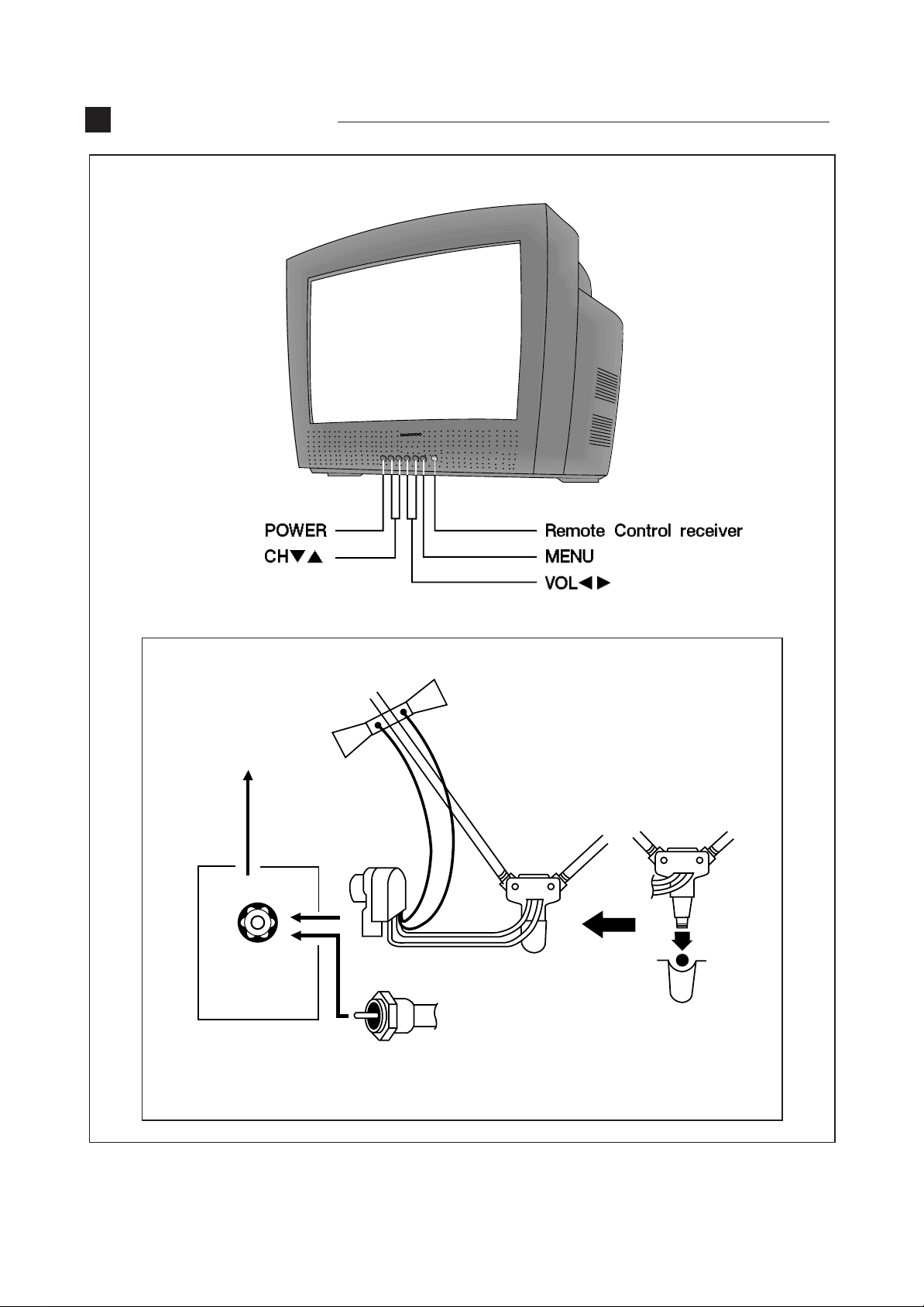
CONTROL VIEW
F-CONNECTOR
300 OHM-75 OHM
COUPLING
TRANSFORMER
VHF
75Ω
FROM 75 OHM
VHF ANTENNA WITH
CABLE OR CABLE
TV SYSTEM
5
Page 4
1. Overview of Your Equipment
Your TV comes with a remote control. The section below summarizes the buttons,controls, and terminals
that you will use with your TV.
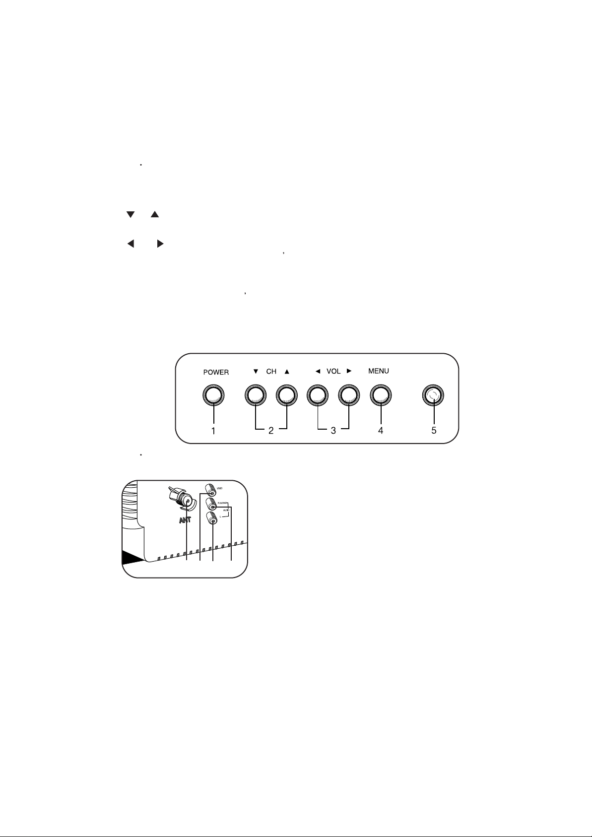
2. Your TV' s Front Panel
1. POWER
Use this buttom to turn your TV on or off.
2. CH
Use these buttom to change channels on your TV, or to select items in the menu system.
3. VOL
Use these buttom to change your TV s volume, to activate selections in the menu system, or to
change audio and video settings.
4. MENU
Use this buttom to turn the TV s menu system on and off.
5. Remote control receiver
This receiver receives a signal from your remote control. Do not block it.
3. Your TV' s Back Panel
1
24
1. Antenna terminal
Use this terminal to attach an antenna or cable
system to your TV.
2. VIDEO IN
This terminal allows the TV to receive a video
signal from another components, such as a VCR.
3. AUDIO R/MONO IN
3
This terminal allows the TV to receive an audio
R/MONO signal from another components, such as
a VCR.
4. AUDIO L IN
This terminal allows the TV to receive an audio L
signal from another components, such as a VCR.
6
Page 5
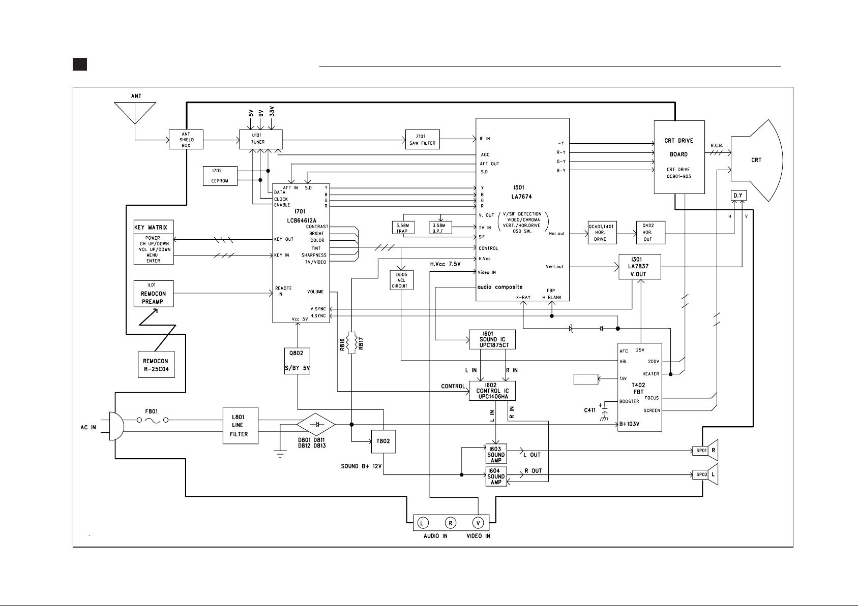
BLOCK DIAGRAM (CN-200I)
8
Page 6
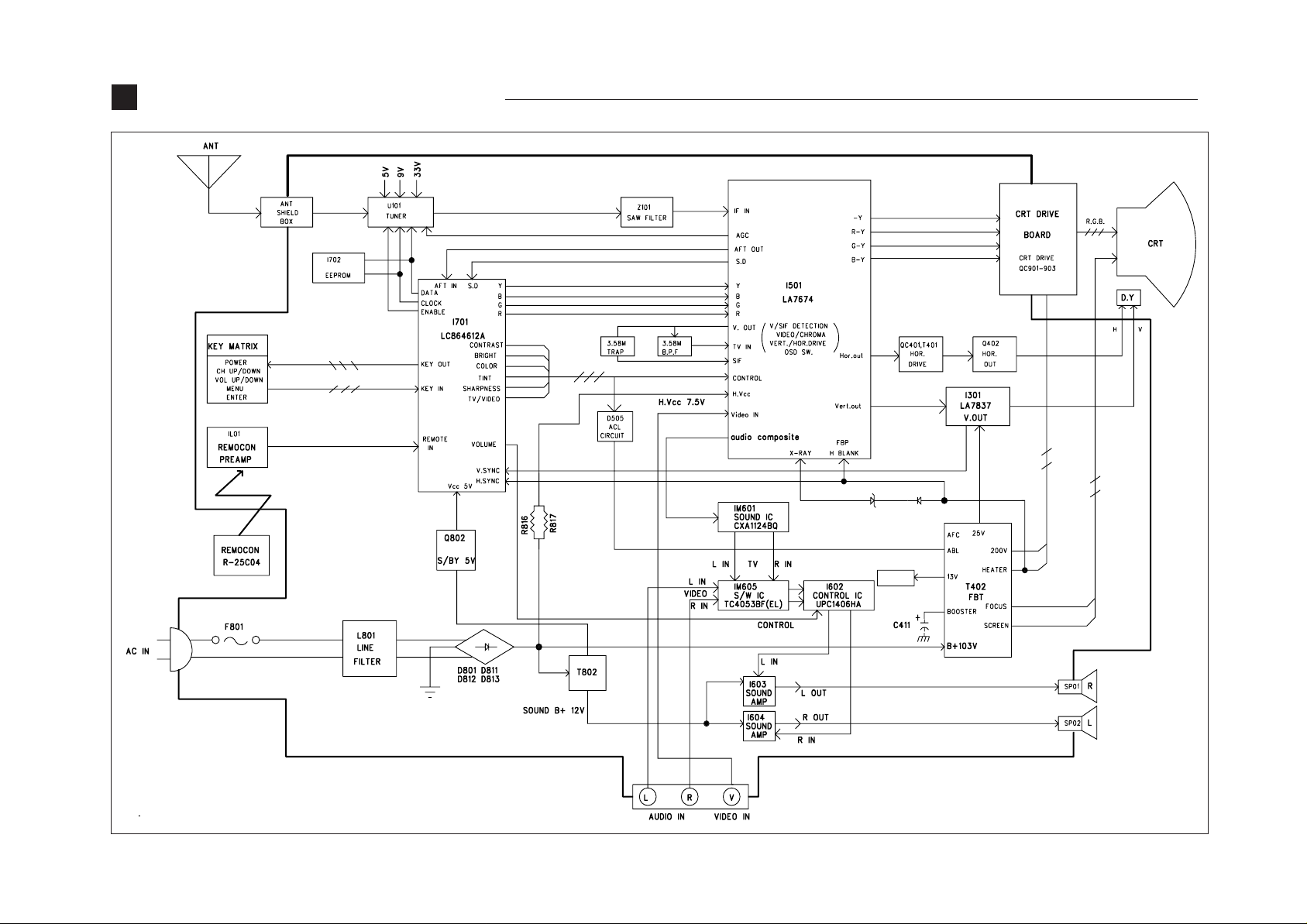
BLOCK DIAGRAM (CN-200A)
9
Page 7

GENERAL ADJUSTMENTS
1. GENERAL
In the majority of cases, all color televisions will need only
slight touch-up adjustment upon installation. Check the basic
characteristics such as height, focus and sub- basic
characteristics such as height, focus and sub- bright. Observe
the picture for good black and white details without
objectionable color shading.
2. VERTICAL HEIGHT ADJUSTMENT
1) Tune in an active channel.
2) Adjust brightness and contrast controls for a good picture.
3) Adjust vertical height control (R305) for approximately one
half inch over scan at top and bottom of picture screen.
4) Vertical centering adjustment R310
Horizontal centering adjustment R516.
3. FOCUS ADJUSTMENT
1) Tune in an active channel.
2) Adjust brightness, sharpness and contrast controls for a
good picture.
3) Adjust focus control (part of T402) for sharp scanning lines
and/or sharp picture.
4. RF AGC ADJUSTMENT
1) Tune in an active channel.
2) Using the attenuator, apply the signal of 60dBm to the
antenna input terminal.
3) Turn RF AGC control (R113) full clockwise until snow
or/and noise appears in the picture, then slowly turn control
counter clockwise until snow or/and noise disappears.
5. HIGH VOLTAGE CHECK
High voltage is not adjustable but must be checked to verify
that the receiver is operating within safe and efficient design
limitations as specified:
1) Operate Receiver for at least 15 minutes at 120V AC line.
2) Set brightness sharpness, contrast and color control to
minumum position (Zero beam).
3) Connect accurate high voltage meter to CRT anode. The
reading should be 26kv~28kv
clockwise.)
4) Rotate the RED, GREEN and BLUE BIAS controls (R917,
R918, R919) counterclock wise from the maximum, set
them to the position where notches in the knobs become
parallel to the surface of P.C. Board.
5) Set the GREEN and BLUE DRIVE controls (R920, R921)
to the mid position.
6) Turn the service switch SW901 (Service Position) on the
CRT board.
7) Rotate the SCREEN control (on T402) gradually
clockwise until the second horizontl line following the first
line appears slightly on the screen. Then turn fully
counterclockwise the two BIAS controls corresponding to
the colors of the first and the second horizontal lines to
eliminated the lines.
8) Set the SCREEN control to the position where the third
horizontal line lights slightly on the screen.
9) Adjust the two BIAS control set to the minimum in item 7)
above to obtain the slightly lighted horizontal line in the
same levels of three (red, green, blue) colors. (The line
should be white if the BIAS controls are adjusted
properly.)
10) Turn the service switch SW901 again (Normal position on
the CRT board.)
11) Press PICTURE-SEL, P-UP and set the brightness and
contrast controls to the maximum.
12) Adjust the BLUE and GREEN DRIVE control to obtain
proper white-blanced picture in high light areas.
13) Using P-SEL, P-DN key, set the brightness and contrast
controls to obtain dark gray raster. Then check the white
balance in low brightness. Of the white balance is not
proper, retouch the BIAS controls and DRIVE controls to
obtain a good white balance in both low and high light
areas.
8. MAIN B+(103V) ADJUSTMENT
1) Tune in an active channel
2) Check TP10 (DC 103V Line) using D.V.M
3) Adjust voltage control (R809) for main B+(DC 103V)
If a correct reading cannot be obtained, check circuity for
malfunctioning components.
6. X-RADIATION PROTECTION CIRCUIT TEST
When service has been performed on the horizontal
deflection system, high voltage system or B+system, the XRADIATION protection circuit must be tested for proper
operation as follows:
1) Operate receiver for at least 15 minutes at 120V AC line.
2) Adjust all customer controls for normal picture and sound.
3) Short R414(X-RAY Short test), and remove short clip.
4) If the operation of horizontal osc. does not stop in step
The circuit must be repaired, before the set is returned to
the customer.
7. CRT GRAY SCALE ADJUSTMENT
1) Tune in an active channel.
2) Set the COLOR control to minimum.
3) Turn the SCREEN control (on T402 fully counter-
9. SUB-BRIGHTNESS ADJUSTMENT
1) Tune in a color program.
2) Set the CONTRAST control to maximum and the
BRIGHTNESS control to maximum and the
SHARPNESS control to the center position.
3) Set the COLOR and TINT controls to center.
4) Set the SUB-BRIGHT control R522 to center and
leave the receiver on five minutes in this state.
5) Watching the picture carefully, adjust the SUB-
BRIGHT control in the position where the picture does
not show evidence of blooming in high brightness area
and not appear too dark in low bright area.
6) Check for BRIGHTNESS controls at both extremes.
7) If the picture does not appear dark with the
CONTRAST and BRIGHTNESS control turned to
minimum, or not appear bright with the controls turned to
maximum, adjust the SUB-BRIGHT control again for an
acceptable picture.
10
Page 8
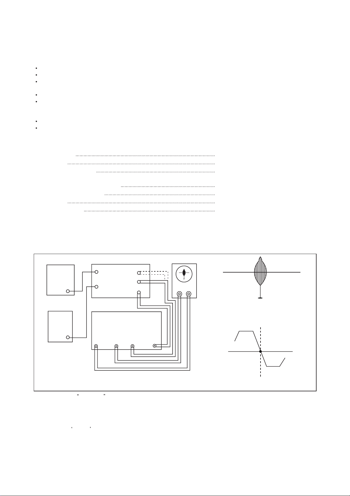
10. PICTURE IF/AFT ADJUSTMENTS
NOTE
: THIS RECEIVER IS TRANSISTORIZED AND SPECIAL CARE MUST BE TAKEN WHEN SERVICING. READ
THE FOLLOWING (NOTES BEFORE ATTEMPTING ALIGNMENT)
Alignment requires an exacting procedure and should be undertaken only when necessary.
Isolation transformer must be used to prevent shock hazard.
The test equipment specified or its equivalent is required to perform the alignment properly. Use of equipment which
does not meet these requirements may result in improper alignment.
Accurate equipment is essential to obtain proper alignment of this receiver.
Use of excessive signal from a sweep generator can cause overloading of receiver circuit Overloading should be
avoided to obtain a true response curve. Insertion of markers from the marker generator should not cause distortion of
the response curve.
The AC Power line voltage should be kept 120 volts while alignment is being performed.
Do not attempt to disconnect any components while the receiver is in operation.
Make sure the power cord is disconnected before replacing any parts in the receiver.
TEST EQUIPMENT
Digital voltmeter National Model VP-2600A or equivalent
Oscilloscope
Direct/Low-capacity probe
Tektronix Model 2215A or equivalent.
Tektronix Model P6120 or equivalent
(Accessory of oscilloscope)
Color-Bar/Dot/Crosshatch generator
PIF sweep marker generator
Power supply
Isolation transformer
Tektronix Model 146 or equivalent.
Nihon Tsushinki Model 4723 or equivalent
Academy Model 150A or equivalent
Voltage adjustable type having capacity of
at least 150 watts
BLOCK DIAGRAM
OUT
OSCILLOSCOPE
Y
X
45.75MHz
Fig. 6 PIF Response
P
45.75MHz
Fig. 7 AFT Response Curve
B+
BIAS
POWER
SUPPLY
A
(12V)
AGC
BIAS
POWER
SUPPLY
B
(4-5V)
1) Disconnect the
MAIN BOARD
TP3
TP5
PIF SWEEP/MARKER GEN.
VH
Fig. 5 Picture IF Sweep Alignment
TP7
TP6
DETIN
TUNER IF output from TP6 and connect equipment as shown above.
2) Set the sweep/marker generator for 30 Vrms.
3) Observe 1 Vp-p on scope by adjusting power supply B (4~5V).
4) Adjust PIF coil L505 for according beat signal with 45.75 MHz marker on scope (See Fig. 6).
5) Connect the
DET IN to TP7.
6) Adjust AFT coil L504 for center display at 45.75 MHz on scope (See Fig. 7).
7) After completing the above steps, disconnect equipment and adjust the AGC delay circuit as explained in the General
Adjustments section of this manual.
11
Page 9
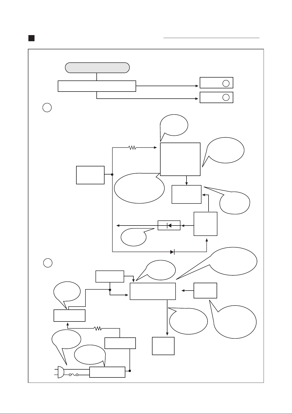
TROUBLE SHOOTING CHARTS
NO POWER
A
DOES QC701(POWER ON/OFF TR)
OPERATE?
CHECK TP10
(MAIN B+
LINE)
R816 15K
2WATT
103V
DC
IF #26 NORMAL
& NO OUTPUT AT
#23 THEN
CHANGE I501
YES
NO
CHECK
#30
(7.5V
DC
)
30
I501
26
Q402
H. OUTPUT
12V 12V
D406
24
GO TO
GO TO
T402
F.B.T
A
B
DOES
SHUT DOWN
CIRCUIT
OPERATE?
CHECK
Q402
COLLECTOR
B
5V
SHOULD
BE
4.3V-5.2V
Q802
REGULATOR
CHECK
F801
125V 5A
CHECK
LEAD
SOLDERING
QC706
RESET
R808
T801
L801
LINE FILTER
CHECK
12V LINE
16
12
NORMAL: 5V
RESET: 0V
I701
LC864616A
QC701
POWER
CONTROL
D403
36
42
OPEN LOAD
THEN CHECK
#42 ON STATE
4 ~5V
103V(B+)
CHECK
ALL THE POINTS
THEN CHANGE
I701
PWR
CONTROL
KEY
KEY OPERATE?
CHECK DIODE
D701 & SWITCH
KEY BOARD
12
Page 10
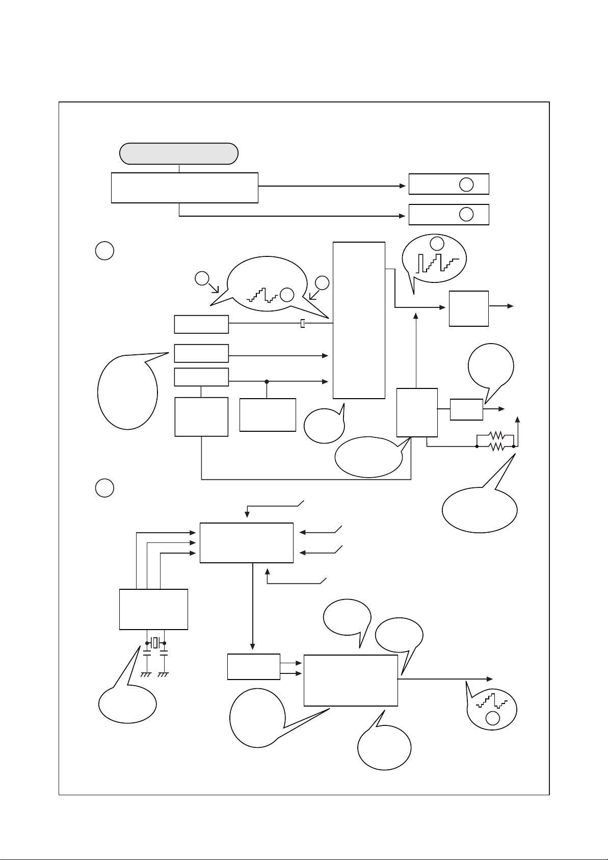
NO PICTURE
C
CHECK
CONTROL
(NORMAL)
VOLTAGES
#39: 5.0V
#31: 3.9V
CHECK THE WAVE FORM OF
I501 #44 (2Vp-p)
FC
QC201
CONTRAST
BRIGHT
D505
ABL
COMPOSITE
VIDEO INPUT
H
R522
SUB-BRIGHT
C506
OK
NG
FS
42
39
31
CHECK
9V LINES
#11,14
I501
LA 7674
11 14
CHECK
ABL
Ib = 1.2mA
21
GO TO
GO TO
Y-OUT
H. BLANKING
T402
FBT
ABL H.T
C
D
H
QC501
VIDEO
DRIVE
CHECK
210V
KINE
D404
R413
R412
D
ENA
I701
LC864616A
CHECK
CSB503E
DATA
1110
CLK
U101 TUNER
IF
Z101
SAW FILTER
CHECK
IF AGC
VTG.
5V
DC
TP2
AGC
5V
9V
V
8
9
T
(33V)
ADJUST
RF-AGC
R113
I501
LA7674
10
DETECTOR
OUTPUT
44
14112
CHECK
9V LINE
#11, 14
CHECK
HEATER
6.3Vrms
TO QC201
H
13
Page 11
NO SOUND(CN-200I)
E
CHECK FOR SIGNAL
AT I501 #1
CHECK
MONO 100% MOD
-> 0.424 Vp-p
CHECK
EXT SOUND
SIGNAL OFF:L
#1
(B+)
#2 9V
#12
#13
#1 9V
(B+)
#2(0~5V)
I602
I601
(MUTE)
#4
#6
#19
#18
#17
CHECK 1Vp-p
CHECK 1Vp-p
MUTE ON: 5V
OFF: 0V
GO TO
GO TO
E
F
F
CHECK SOUND INPUT
CHECK 9V
Z201
CHECK SOUNDIF INPUT
#11
#14
#44
#48
#8(0~5V)
I604/I603
#3
I501
LA7674
#7
#6
#5
CHECK 12VDC
CHECK SOUND OUTPUT
COMPOSITE SIGNAL
#1
#4
CHECK FM DET
CIRCUIT
I601 #1
14
Page 12

NO SOUND(CN-200A)
E
CHECK FOR SIGNAL
AT I501 #1
CHECK
MONO 100% MOD
-> 0.693 Vp-p
CHECK 4.5V
#38
(B+)
#30 9V
#2(9VDC)
IM601
#39
#40
#1 9V
(B+)
#2 (0~5V)
I602
(MUTE)
#4
#6
#22
#21
#20
L OUT
#15
R OUT
#13
#8
CHECK 1Vp-p
CHECK 4.5V
CHECK R/L OUTPUT
MUTE ON: 5V
OFF: 0V
GO TO
GO TO
E
F
F
CHECK SOUND INPUT
CHECK 9V
Z201
CHECK SOUND IF INPUT
#11
#14
#44
#48
#8 (0~5V)
I604/I603
#3
I501
LA7674
#7
#6
#5
CHECK 12VDC
CHECK SOUND OUTPUT
COMPOSITE SIGNAL
#1
#4
CHECK FM DET
CIRCUIT
I601 #1
15
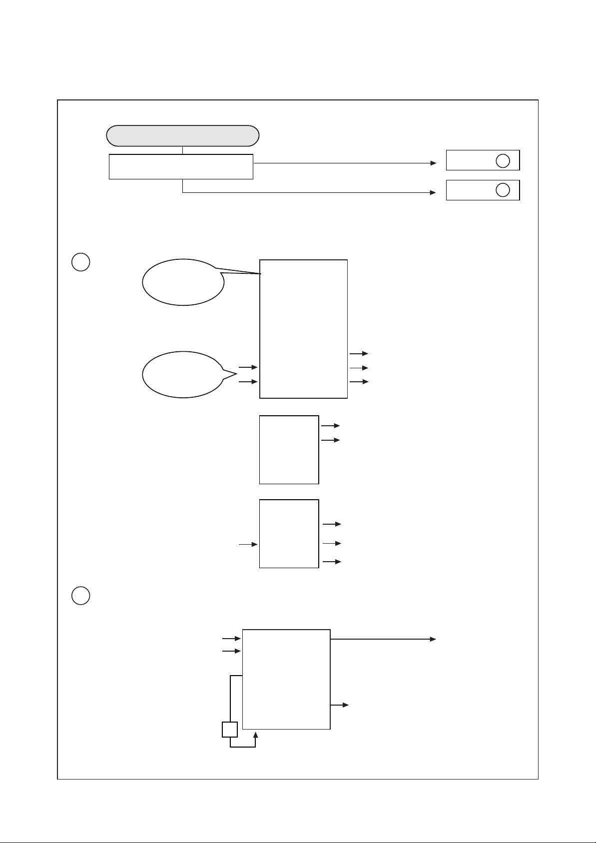
Page 13

CH DON'T STOP
G
CHECK INPUT SIGNAL
CONDITIONS
U101
TUNER
2 3
I701
LC864616A
4
13
33
IF OUTPUT
CHECK
AFT WINDOW
VTG.
1.6V ~ 3.4V
ADJUST
RF AGC
R113
L: NO SIGNAL
H: SIGNAL
GOOD
BAD
8, 9
10
47
I501
LA7674
GO TO
LOSS OF SIGNAL OR
WEAK SIGNAL
45
46
9
8
AFT
PIF
ADJUST
PIF & AFT
REFER TO GENERAL
ADJUSTMENTS
G
S.D SIGNAL
DETECTION
16
44
Page 14

NO COLOR
CENTER
3.5V
TINT
41
CHECK
DC
9V
11
COMPOSITE
VIDEO
COLOR
C506
CENTER
4V
36
42
FS
QC201
Emitter
FC
NO VERTICAL DEFLECTION
CHECK 9V
DC
I501
LA7674
12
X502
APC FILTER
13
CHECK
CRYSTAL
CHECK
9V
DC
3.579545MHZ
14
18
19
20
21
CHECK 9V
R-Y
G-Y
B-Y
LUMINANCE (-Y) VIDEO B (210V)
CHECK
CONNECTOR
P901
CC
Q901
Q902
Q903
R
G
B
+
I501
LA7674
14
28
CHECK
VERT.OUT
R301
VR305 V,HEIGHT
R311
1
I301
LA7837
2
48
12
R304
R305
C307
+
V.D.Y.
17
CHECK 25V
D402 R417
C413
C417
CHECK THE WAVEFORM
I301 #12 NO OUTPUT:
CHANGE IC301
DC
Page 15

ON SCREEN DISPLAY DOES NOT OPERATE
CHECK
FOR,60Hz
/ VS
19
21
22
/ HS
20
I701
23
24
10
CHECK
FOR, 15, 734Hz
11
OSC CHECK
REMOTE CONTROL DOES NOT OPERATE
IL01
REMOCON
SENSOR
GND 5V OUT
R
G
B
BL
R, G, B, BL
CHANGE
IF OSD DOES NOT
OPERATE, CHANGE
I701
I701 LC864616A
CHECK
WAVEFORM
34
18
Page 16

PIN ASSIGN OF IC LC864616A(I701)
VIDEO MUTE(O)
DATA(O)
CLOCK(O)
ENABLE(O)
SOUND MUTE(O)
TV/VIDEO(O)
MPX1(O)
MPX2(O)
1 P10
2 P11
3 P12
4 P13
5 P14
6 P15
7 P16
8 P17
9 DVss
10 CF1
11 CF2
P07 42 POWER(O)
KEY OUT
41P06
KEY OUT
40P05
KEY OUT
39P04
KEY IN
38P03
KEY IN
37P02
KEY IN
36P01
KEY IN
35P00
34P73/INT3/TOIN REMOCON(IN)
33P72/INT2/TOIN SD(IN)
32P71/INT1 X-Ray IN
3-LAN
MN/ST
CH UP
SAP TV/VID
EEPROM
VOL + POWER
VOL -CH DN
MENU
:
Switch
:
Option
Diode
AFC IN
N. C
N. C
1Vpp IN
12 DVdd
13 P90/AN0
14 P91/AN1
15 P92/AN2
16 /RESET
17 FILT
18 CVIN
19 /VS
20 /HS
21 R 22G
NOTE) CF is used 503KHz RESONATOR
31P70/INT0 AC 60Hz IN
30PWM5 CONTRAST
29PWM4 BRIGHTNESS
28PWM3 COLOR
27PWM2 TINT
26PWM1 SHARPNESS
25PWM0 VOLUME
24BL
23B
19
Page 17

TROUBLE SHOOTING CHARTS
NO POWER
A
DOES QC701(POWER ON/OFF TR)
OPERATE?
CHECK TP10
(MAIN B+
LINE)
R816 15K
2WATT
103V
DC
IF #26 NORMAL
& NO OUTPUT AT
#23 THEN
CHANGE I501
YES
NO
CHECK
#30
(7.5V
DC
)
30
I501
26
Q402
H. OUTPUT
12V 12V
D406
24
GO TO
GO TO
T402
F.B.T
A
B
DOES
SHUT DOWN
CIRCUIT
OPERATE?
CHECK
Q402
COLLECTOR
B
5V
SHOULD
BE
4.3V-5.2V
Q802
REGULATOR
CHECK
F801
125V 5A
CHECK
LEAD
SOLDERING
QC706
RESET
R808
T801
L801
LINE FILTER
CHECK
12V LINE
16
12
NORMAL: 5V
RESET: 0V
I701
LC864616A
QC701
POWER
CONTROL
D403
36
42
OPEN LOAD
THEN CHECK
#42 ON STATE
4 ~5V
103V(B+)
CHECK
ALL THE POINTS
THEN CHANGE
I701
PWR
CONTROL
KEY
KEY OPERATE?
CHECK DIODE
D701 & SWITCH
KEY BOARD
12
Page 18

NO PICTURE
C
CHECK
CONTROL
(NORMAL)
VOLTAGES
#39: 5.0V
#31: 3.9V
CHECK THE WAVE FORM OF
I501 #44 (2Vp-p)
FC
QC201
CONTRAST
BRIGHT
D505
ABL
COMPOSITE
VIDEO INPUT
H
R522
SUB-BRIGHT
C506
OK
NG
FS
39
31
CHECK
9V LINES
#11,14
I501
LA 7674
42
11 14
CHECK
ABL
Ib = 1.2mA
21
GO TO
GO TO
Y-OUT
H. BLANKING
T402
FBT
ABL H.T
C
D
H
QC501
VIDEO
DRIVE
CHECK
210V
KINE
D404
R413
R412
D
ENA
I701
LC864616A
CHECK
CSB503E
DATA
1110
CLK
U101 TUNER
IF
Z101
SAW FILTER
CHECK
IF AGC
VTG.
5V
DC
TP2
AGC
5V
9V
V
8
9
T
(33V)
ADJUST
RF-AGC
R113
I501
LA7674
10
DETECTOR
OUTPUT
44
14112
CHECK
9V LINE
#11, 14
CHECK
HEATER
6.3Vrms
TO QC201
H
13
Page 19

NO SOUND(CN-200I)
E
CHECK FOR SIGNAL
AT I501 #1
CHECK
MONO 100% MOD
-> 0.424 Vp-p
CHECK
EXT SOUND
SIGNAL OFF:L
#1
(B+)
#2 9V
#12
#13
#1 9V
(B+)
#2(0~5V)
I602
I601
(MUTE)
#4
#6
#19
#18
#17
CHECK 1Vp-p
CHECK 1Vp-p
MUTE ON: 5V
OFF: 0V
GO TO
GO TO
E
F
F
CHECK SOUND INPUT
CHECK 9V
Z201
CHECK SOUNDIF INPUT
#11
#14
#44
#48
#8(0~5V)
I604/I603
#3
I501
LA7674
#7
#6
#5
CHECK 12VDC
CHECK SOUND OUTPUT
COMPOSITE SIGNAL
#1
#4
CHECK FM DET
CIRCUIT
I601 #1
14
Page 20

NO SOUND(CN-200A)
E
CHECK FOR SIGNAL
AT I501 #1
CHECK
MONO 100% MOD
-> 0.693 Vp-p
CHECK 4.5V
#38
(B+)
#30 9V
#2(9VDC)
IM601
#39
#40
#1 9V
(B+)
#2 (0~5V)
I602
(MUTE)
#4
#6
#22
#21
#20
L OUT
#15
R OUT
#13
#8
CHECK 1Vp-p
CHECK 4.5V
CHECK R/L OUTPUT
MUTE ON: 5V
OFF: 0V
GO TO
GO TO
E
F
F
CHECK SOUND INPUT
CHECK 9V
Z201
CHECK SOUND IF INPUT
#11
#14
#44
#48
#8 (0~5V)
I604/I603
#3
I501
LA7674
#7
#6
#5
CHECK 12VDC
CHECK SOUND OUTPUT
COMPOSITE SIGNAL
#1
#4
CHECK FM DET
CIRCUIT
I601 #1
15
Page 21

CH DON'T STOP
G
CHECK INPUT SIGNAL
CONDITIONS
U101
TUNER
2 3
I701
LC864616A
4
13
33
IF OUTPUT
CHECK
AFT WINDOW
VTG.
1.6V ~ 3.4V
ADJUST
RF AGC
R113
L: NO SIGNAL
H: SIGNAL
GOOD
BAD
8, 9
10
47
I501
LA7674
GO TO
LOSS OF SIGNAL OR
WEAK SIGNAL
45
46
9
8
AFT
PIF
ADJUST
PIF & AFT
REFER TO GENERAL
ADJUSTMENTS
G
S.D SIGNAL
DETECTION
16
44
Page 22

NO COLOR
CENTER
3.5V
TINT
41
CHECK
DC
9V
11
COMPOSITE
VIDEO
COLOR
C506
CENTER
4V
36
42
FS
QC201
Emitter
FC
NO VERTICAL DEFLECTION
CHECK 9V
DC
I501
LA7674
12
X502
APC FILTER
13
CHECK
CRYSTAL
CHECK
9V
DC
3.579545MHZ
14
18
19
20
21
CHECK 9V
R-Y
G-Y
B-Y
LUMINANCE (-Y) VIDEO B (210V)
CHECK
CONNECTOR
P901
CC
Q901
Q902
Q903
R
G
B
+
I501
LA7674
14
28
CHECK
VERT.OUT
R301
VR305 V,HEIGHT
R311
1
I301
LA7837
2
48
12
R304
R305
C307
+
V.D.Y.
17
CHECK 25V
D402 R417
C413
C417
CHECK THE WAVEFORM
I301 #12 NO OUTPUT:
CHANGE IC301
DC
Page 23

ON SCREEN DISPLAY DOES NOT OPERATE
CHECK
FOR,60Hz
/ VS
19
21
22
/ HS
20
I701
23
24
10
CHECK
FOR, 15, 734Hz
11
OSC CHECK
REMOTE CONTROL DOES NOT OPERATE
IL01
REMOCON
SENSOR
GND 5V OUT
R
G
B
BL
R, G, B, BL
CHANGE
IF OSD DOES NOT
OPERATE, CHANGE
I701
I701 LC864616A
CHECK
WAVEFORM
34
18
Page 24

PIN ASSIGN OF IC LC864616A(I701)
VIDEO MUTE(O)
DATA(O)
CLOCK(O)
ENABLE(O)
SOUND MUTE(O)
TV/VIDEO(O)
MPX1(O)
MPX2(O)
1 P10
2 P11
3 P12
4 P13
5 P14
6 P15
7 P16
8 P17
9 DVss
10 CF1
11 CF2
P07 42 POWER(O)
KEY OUT
41P06
KEY OUT
40P05
KEY OUT
39P04
KEY IN
38P03
KEY IN
37P02
KEY IN
36P01
KEY IN
35P00
34P73/INT3/TOIN REMOCON(IN)
33P72/INT2/TOIN SD(IN)
32P71/INT1 X-Ray IN
3-LAN
MN/ST
CH UP
SAP TV/VID
EEPROM
VOL + POWER
VOL -CH DN
MENU
:
Switch
:
Option
Diode
AFC IN
N. C
N. C
1Vpp IN
12 DVdd
13 P90/AN0
14 P91/AN1
15 P92/AN2
16 /RESET
17 FILT
18 CVIN
19 /VS
20 /HS
21 R 22G
NOTE) CF is used 503KHz RESONATOR
31P70/INT0 AC 60Hz IN
30PWM5 CONTRAST
29PWM4 BRIGHTNESS
28PWM3 COLOR
27PWM2 TINT
26PWM1 SHARPNESS
25PWM0 VOLUME
24BL
23B
19
Page 25

DESCRIPTION OF SEMICONDUCTORS
LA7674 (VIF/SIF/VIDEO/CHROMA/DEFLECTION)
1. Case Outline : SDIP 52P
2. Pin Connections/Block Diagram
IC501 LA7674
IF/VIDEO/CHROMA/DEF
FM DET
IF AGC
EX AIN
FM DET
NFB
A
OUT
GND
IF
IF IN
RF AGC
VCC
APC
VXO
VCC
R
1
LOCK
DET
2
3
4
5
ATT
FM-
DET
FM-
6
DET
7
8
IN
VIF
AMP
9
RF-
10
AGC
11
12
13
14
15
IN
VCO
AGC
TINT
IF-
APC
ACC
KILL-
ER
VIDEO
DET
LIM
AMP
APC
DET
VCO
VIDEO
AMP
AFT
52
51
50
49
48
47
46
45
44
43
42
41
40
39
38
IFAPC
VCD
VCO
RF AGC
SIF
IN
AFT OUT
AFT
AFT
V
DET
AV S.W
IN V
IN
TINT
EX. VIN
CONT
VIDEO
R-Y
G-Y
B-Y
FBP
HOUT
HOD
HOSC
HAFC
GIN
BIN
-Y
OSD
16
17
18
19
20
OSD-SWITCH
CARRIER-F
FBT-DET
-Y OUT
COLOR
DEMO
2NA
BPA
SOFT
IST
BPA
BLACK
EXPAND
CONTRAST
SHARP
21
DRIVER
HOR
FBTDET
FBT-DET
-Y OUT
AFC
2
CLAMP
BRIGHT
D.L
22
IN
23
24
25
26
OSC
HOR
AFC
1
HOR
C/D
SYNC/
SEP
VER
SYNC-
SEP
VER
C/D
HOR
COIN
37
36
35
34
33
32
31
30
29
28
27
GND
COLOR
BDET
Y
IN
SHARP
CLAMP
BRIGHT
V
CCH
S. SEP
V. OUT
H.DET
20
Page 26

DTQ-26S1FC/FS/FSP/HC/HS/HSP
EXPLODED VIEW
23
Page 27

DTQ-29S1FCN/FSN/FSP/HC/HS/HSP
EXPLODED VIEW
24
Page 28

Page 29

Page 30

Page 31

Page 32

Page 33

Page 34

Page 35

 Loading...