


S/M No.:TCN001MEF0
Service Manual
Color Television
CHASSIS : CN-001M
Model
DTQ-14P2/P3FCM
DTQ-14P2/V1FCWM/P2SCM
DTQ-14V1/V5FCM/V1/V4SCM
DTQ-14V5FCNM/15U5SCM
DTQ-14V6FCBM/FCPM/FBBM/FPPM
DTQ-14J4FCGM/FCCM
DTQ-20V1/V4/V5FCM
DTQ-20V1/V4SCM
DTQ-20P2/P3FCM/P2SCM
U.S.A
CANADA
(AC120V)
DTQ-14V6NBM/NPM
DTQ-14V1/V3/V5FSM
DTQ-14V1/V3/V4/V5/V8/V9SSM
DTQ-14U1FSM/SSM/20U1FSM/SSM
DTQ-20P2SSM/15U5FSM
DTQ-20V1/V3/V4FSM
DTQ-20V1/V3/V4/V8/V9SSM
DTQ-14V1/V4/V5FSPM
DTQ-14V1/V4/V5/U1SSPM
DTQ-14V6NBPM/NPPM
DTQ-20V1/V4FSPM
DTQ-20V1/V3/V4/U1SSPM
DTQ-15U5SSPM
DTQ-14V1/V4SSFM
DTQ-20V1/V4SSFM
DTQ-14V4/20V4FCFM
✔
Caution
: In this Manual, some parts can be changed for improving, their
performance without notice in the parts list. So, if you need the
latest parts information,please refer to PPL(Parts Price List) in
Service Information Center (http://svc.dwe.co.kr).
Korea, USA, Japen(AC90~250V)
Middle America
(AC 110V)
Chile, Peru, Philippines
(AC220V)
Dominica
(AC60~180)
DAEWOO ELECTRONICS CO., LTD
: //svc.dwe.co.kr
http
May. 2002

TABLE OF CONTENTS
SAFETY PRECAUTIONS.................................................................................................................... 2
PRODUCT SAFTY SERVICING GUIDELINES FOR AUDIO - VIDEO PRODUCS......................................... 2
PRODUCT SAFTY SERVICING GUIDELINES FOR COLOR TELEVISION RECEIVERS............................. 3
SPECIFICATIONS ............................................................................................................................... 5
BLOCK DIAGRAM .............................................................................................................................. 6
ALIGNMENT INSTRUCTIONS............................................................................................................ 7
SERVICE MODE ADJUSTMENTS.................................................................................................................. 7
ASSEMBLY ADJUSTMENTS .......................................................................................................................... 8
PARENTAL CONTROL PASSWORD SETTINGS...........................................................................................12
VOLTAGE CHART ..............................................................................................................................13
WAVEFORMS......................................................................................................................................16
SCHEMATIC DIAGRAM......................................................................................................................19
EXPLODED VIEW ...............................................................................................................................20
ELECTRICAL PARTS LIST.................................................................................................................28
APPENDIX (Appendix is provide only by internet [http://svc.dwe.co.kr])
IC DESCRIPTION ................................................................................................................................ 1
TROUBLE SHOOTING CHARTS........................................................................................................ 8
NO POWER ..................................................................................................................................................... 8
NO PICTURE................................................................................................................................................... 9
NO SOUND...................................................................................................................................................... 10
CH DON’T MEMORY or CH SKIP ................................................................................................................. 11
NO COLOR...................................................................................................................................................... 12
NO VERTICAL DEFLECTION ......................................................................................................................... 12
NO ON-SCREEN DISPLY ............................................................................................................................... 13
REMOTE CONTROL DOES NOT OPERATE ................................................................................................. 13
1
PRODUCT SAFETY SERVICING GUIDELINES FOR AUDIO - VIDEO PRODUCTS
CAUTION
NEVER PERFORM CUSTOMIZED INSTALLATIONS WITHOUT MANUFACTURER'S APPROVAL. UNAUTHORIZED MODIFICATIONS WILL NOT ONLY VOID
THE WARRANTY, BUT MAY LEAD TO YOUR BEING LIABLE FOR ANT RESULTING PROPERTY DAMAGE OR USER INJURY.
SERVICE WORK SHOULD BE PERFORMED ONLY AFTER YOU ARE THOROUGHLY FAMILIAR WITH ALL OF THE FOLLOWING SAFETY CHECKS AND
SERVICING GUIDELINES. TO DO OTHERWISE, INCREASES THE RISK OF
POTENTIAL HAZARDS AND INJURY TO THE USER.
WHILE SERVICING, USE AN ISOLATION TRANSFORMER FOR PROTECTION
FROM A.C. LINE SHOCK.
: DO NOT ATTEMPT TO MODIFY THIS PRODUCT IN ANY WAY.
SAFETY CHECKS
AFTER THE ORIGINAL SERVICE PROBLEM HAS BEEN CORRECTED, A CHECK
SHOULD BE MADE OF THE FOLLOWING:
SUBJECT:FIRE & SHOCK HAZARD
1. BE SURE THAT ALL COMPONENTS ARE POSITIONED IN SUCH A WAY AS
TO AVOID POSSIBILITY OF ADJACENT COMPONENT SHORTS. THIS IS
ESPECIALLY IMPORTANT ON THOSE MODULES WHICH ARE TRANSPORTED TO AND FROM THE REPAIR SHOP.
2. NEVER RELEASE A REPAIR UNLESS ALL PROTECTIVE DEVICES SUCH AS
INSULATORS, BARRIERS, COVERS, SHIELDS, STRAIN RELIEFS, POWER
SUPPLY CORDS, AND OTHER HARDWARE HAVE BEEN REINSTALLED PER
ORIGINAL DESIGN. BE SURE, THAT THE SAFETY PURPOSE OF THE
POLARIZED LINE PLUG HAS NOT BEEN DEFEATED.
3. SOLDERING MUST BE INSPECTED TO DISCOVER POSSIBLE COLD SOLDER JOINTS, SOLDER SPLASHES OF SHARP SOLDER POINTS. BE CERTAIN TO REMOVE ALL LOOSE FOREIGN PARTICLES.
4. CHECK FOR PHYSICAL EVIDENCE OF DAMAGE OR DETERIORATION TO
PARTS AND COMPONENTS, FOR FRAYED LEADS, DAMAGED INSULATION
(INCLUDING A.C. CORD), AND REPLACE IF NECESSARY. FOLLOW ORIGINAL LAYOUT, LEAD LENGTH AND DRESS.
5. NO LEAD OR COMPONENT SHOULD TOUCH A RECEIVING TUBE OR A
RESISTOR RATED AT 1 WATT OR MORE. LEAD TENSION AROUND PROTRUDING METAL SURFACES MUST BE AVOIDED.
6. ALL CRITICAL COMPONENTS SUCH AS FUSES, FLAMEPROOF RESISTOR,
CAPACITORS, ETC. MUST BE REPLACED WITH EXACT FACTORY TYPES.
DO NOT USE REPLACEMENT COMPONENTS OTHER THAN THOSE SPECIFIED OR MAKE UNRECOMMENDED CIRCUIT MODIFICATIONS.
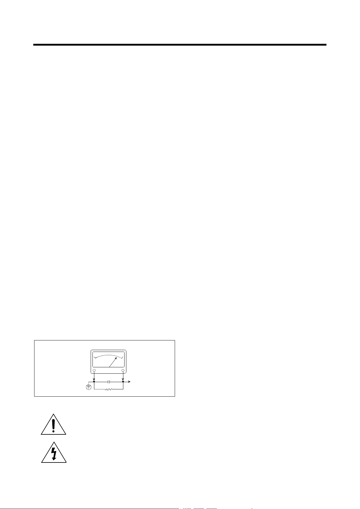
7. AFTER RE-ASSEMBLY OF THE STE ALWAYS PERFORM AN A.C. LEAKAGE
TEST ON ALL EXPOSED METALLIC PARTS OF THE CABINET. (THE CHANNEL SELECTOR KNOB, ANTENNA TERMINALS, HANDLE AND SCREWS) TO
BE SURE THE SET IS SAFE TO OPERATE WITHOUT DANGER OF ELECTRICAL SHOCK. DO NOT USE A LINE ISOLATION TRANSFORMER DURING
THIS TEST USE AN A.C. VOLTMETER, HAVING 5000 OHMS PER VOLT OR
MORE SENSITIVITY, IN THE FOLLOWING MANNER : CONNECT A 1500 OHM
10 WATT RESISTOR, PARALLELED BY A .15 MFD. 150V A.C. TYPE CAPACITOR BETWEEN A KNOWN GOOD EARTH GROUND (WATER POPE, CONDUIT, ETC.) AND THE EXPOSED METALLIC PARTS, ONE AT A TIME.
MEASURE THE A.C. VOLTAGE ACROSS THE COMBINATION OF 1500 OHM
RESISTOR AND .15 MFD CAPACITOR. REVERSE THE A.C. PLUG AND
REPEAT A.C. VOLTAGE MEASUREMENTS FOR EACH EXPOSED METALLIC
PART. VOLTAGE MEASURED MUST NOT EXCEED .75 VOLTS R.M.S THIS
CORRESPONDS TO 0.5 MILLIAMP A.C. NAY VALUE EXCEEDING THIS LIMIT
CONSTITUTES A POTENTIAL SHOCK HAZARD AND MUST BE CORRECTED
IMMEDIATELY.
A.C. VOLTMETER
0.15 uF
GOOD EARTH GROUND
SUCH AS THE WATER
PIPE, CONDUIT, ETC.
1500 OHM
10WATT
PLACE THIS PROBE
ON EACH EXPOSED
METAL PART
SUBJECT : GRAPHIC SYMBOLS
THE LIGHTNING FLASH WITH ARROWHEAD SYMBOL,
WITHIN AN EQUILATERAL TRIANGLE, IS INTENDED
TO ALERT THE SERVICE PERSONNEL TO THE PRESENCE OF UNINSULATED “DANGEROUS VOLTAGE”
THAT MAY BE OF SUFFICIENT MAGNITUDE TO CONSTITUTE A RISK OF ELECTRIC SHOCK.
THE EXCLAMATION POINT WITHIN AN EQUILATERAL
TRIANGLE IS INTENDED TO ALERT THE SERVICE
PERSONNEL TO THE PRESENCE OF IMPORTANT
SAFETY INFORMATION ON SERVICE LITERATURE.
SUBJECT : X-RADIATION
1. BE SURE PROCEDURES AND INSTRUCTIONS TO ALL SERVICE PERSONNEL COVER THE SUBJECT OF X-RADIATION. THE ONLY POTENTIAL
SOURCE OF X-RAYS IN CURRENT T.V. RECEIVERS IS THE PICTURE TUBE.
HOWEVER, THIS TUBE DOES NOT EMIT X-RAYS WHEN THE HIGH VOLTAGE IS AT THE FACTORY SPECIFIED LEVEL. THE PROPER VALUE IS
GIVEN IN THE APPLICABLE SCHEMATIC. OPERATION AT HIGHER VOLTAGES MAY CAUSE A FAILURE OF THE PICTURE TUBE OR HIGH VOLTAGE
SUPPLY AND UNDER CERTAIN CIRCUMSTANCES, AMY PRODUCE RADIATION IN EXCESS OF DESIRABLE LEVELS.
2. ONLY FACTORY SPECIFIED C.R.T ANODE CONNECTORS MUST BE USED.
DEGAUSSING SHIELDS ALSO SERVE AS X-RAY SHIELD IN COLOR SETS.
ALWAYS RE-INSTALL THEM.
3. IT IS ESSENTIAL THAT SERVICE PERSONNEL HAVE AVAILABLE AN ACCURATE AND RELIABLE HIGH VOLTAGE METER. THE CALIBRATION OF THE
METER SHOULD BE CHECKED PERIODICALLY AGAINST A REFERENCE
STANDARD. SUCH AS THE ONE AVAILABLE AT YOUR DISTRIBUTOR.
4. WHEN THE HIGH VOLTAGE CIRCUITRY IS OPERATING PROPERLY THERE
IS NO POSSIBILITY OF AN X-RADIATION PROBLEM. EVERY TIME A COLOR
CHASSIS IS SERVICED, THE BRIGHTNESS SHOULD BE RUN UP AND
DOWN WHILE MONITORING THE HIGH VOLTAGE WITH A METER TO BE
CERTAIN THAT THE HIGH VOLTAGE DOES NOT EXCEED THE SPECIFIED
VALUE AND THAT IT IS REGULATING CORRECTLY. WE SUGGEST THAT
YOU AND YOUR SERVICE ORGANIZATION REVIEW TEST PROCEDURES
SO THAT VOLTAGE REGULATION IS ALWAYS CHECKED AS A STANDARD
SERVICING PROCEDURE, AND THAT THE HIGH VOLTAGE READING BE
RECORDED ON EACH CUSTOMER’S INVOICE.
5. WHEN TROUBLESHOOTING AND MAKING TEST MEASUREMENTS IN A
PRODUCT WITH A PROBLEM OF EXCESSIVE HIGH VOLTAGE, AVOID
BEING UNNECESSARILY CLOSE TO THE PICTURE TUBE AND THE HIGH
VOLTAGE SUPPLY. DO NOT OPERATE THE PRODUCT LONGER THAN IS
NECESSARY TO LOCATE THE CAUSE OF EXCESSIVE VOLTAGE.
6. REFER TO HV, B+ AND SHUTDOWN ADJUSTMENT PROCEDURES
DESCRIBED IN THE APPROPRIATE SCHEMATIC AND DIAGRAMS (WHERE
USED).
SUBJECT : IMPLOSION
1. ALL DIRECT VIEWED PICTURE TUBES ARE EQUIPPED WITH AN INTEGRA
IMPLOSION PROTECTION SYSTEM. BUT CARE SHOULD BE TAKEN TO
AVOID DAMAGE DURING INSTALLATION. AVOID SCRATCHING THE
TUBE. OF SCRATCHED REPLACE IT.
2. USE ONLY RECOMMENDED FACTORY REPLACEMENT TUBES.
SUBJECT : TIPS ON PROPER INSTALLATION
1. NEVER INSTALL ANY PRODUCT IN A CLOSED-IN RECESS, CUBBYHOLE OR
CLOSELY FITTING SHELF SPACE, OVER OR CLOSE TO HEAT DUCT, OR IN
THE PATH OF HEATED AIR FLOW.
2. AVOID CONDITIONS OF HIGH HUMIDITY SUCH AS: OUTDOOR PATIO
INSTALLATIONS WHERE DEW IS A FACTOR, NEAR STEAM RADIATORS
WHERE STEAM LEAKAGE IS A FACTOR, ETC.
3. AVOID PLACEMENT WHERE DRAPERIES MAY OBSTRUCT REAR VENTING.
THE CUSTOMER SHOULD ALSO AVOID THE USE OF DECORATIVE
SCARVES OR OTHER COVERINGS WHICH MIGHT OBSTRUCT VENTILATION.
4. WALL AND SHELF MOUNTED INSTALLATIONS USING A COMMERCIAL
MOUNTING KIT, MUST FOLLOW THE FACTORY APPROVED MOUNTING
INSTRUCTIONS. A PRODUCT MOUNTED TO A SHELF OR PLATFORM MUST
RETAIN ITS ORIGINAL FEET (OR THE EQUIVALENT THICKNESS IN SPACERS)TO PROVIDE ADEQUATE AIR FLOW ACROSS THE BOTTOM, BOLTS
OR SCREWS USED FOR FASTENERS MUST NOT TOUCH ANY PARTS OR
WIRING. PERFORM LEAKAGE TEST ON CUSTOMIZED INSTALLATIONS.
5. CAUTION CUSTOMERS AGAINST THE MOUNTING OF A PRODUCT ON
SLOPING SHELF OR A TILTED POSITION, UNLESS THE PRODUCT IS
PROPERLY SECURED.
6. A PRODUCT ON A ROLL-ABOUT CART SHOULD BE STABLE ON ITS MOUNTING TO THE CART. CAUTION THE CUSTOMER ON THE HAZARDS OF TRYING TO ROLL A CART WITH SMALL CASTERS ACROSS THRESHOLDS OR
DEEP PILE CARPETS.
7. CAUTION CUSTOMERS AGAINST THE USE OF A CART OR STAND WHICH
HAS NOT BEEN LISTED BY UNDERWRITERS LABORATORIES. INC. FOR
USE WITH THEIR SPECIFIC MODEL OF TELEVISION RECEIVER OR
GENERICALLY APPROVED FOR USE WITH T.V.S OF THE SAME OR
LARGER SCREEN SIZE.
8. CAUTION CUSTOMERS AGAINST THE USE OF EXTENSION CORDS,
EXPLAIN THAT A FOREST OF EXTENSIONS SPROUTING FROM A SINGLE
OUTLET CAN LEAD TO DISASTROUS CONSEQUENCES TO HOME AND
FAMILY.
2
PRODUCT SAFETY SERVICING GUIDELINES FOR COLOR TELEVISION RECEIVERS
CAUTION : Do not attempt to modify this product in any way. Unauthorized modifications will not only void the warranty, but may lead to
your being liable for any resulting property damage or user injury.
Service work should be performed only after you are thoroughly
familiar with all of the following safety checks and servicing guidelines. To do otherwise, increases the risk of potential hazards and
injury to the user.
SAFETY CHECKS
After the original service problem has been corrected, a check should
be made of the following:
SUBJECT : FIRE & SHOCK HAZARD
1. Be sure that all components are positioned in such a way as to
avoid possibility of adjacent component shorts. This is especially
important on those chassis which are transported to and from the
repair shop.
2. Never release a repair unless all protective devices such as insulators, barriers, covers, shields, strain reliefs, and other hardware
have been reinstalled per original design.
3. Soldering must be inspected to discover possible cold solder joints,
frayed leads, damaged insulation (including A.C. cord), solder
splashes or sharp solder points. Be certain to remove all loose foreign particals.
4. Check for physical evidence of damage or deterioration to parts
and components, and replace if necessary follow original layout,
lead length and dress.
5. No leads or components should touch a receiving tube or a resistor
rated at 1 watt or more. Lead tension around protruding metal surfaces must be avoided.
6. All critical components such as fuses, flameproof resistors, capacitors, etc. must be replaced with exact factory types. Do not use
replacement components other than those specified or make
unrecommended circuit modifications.
7. After re-assembly of the set always perform an A.C. leakage test
on all exposed metallic parts of the cabinet, (the channel selector
knob, antenna terminals, handle and screws) to be sure the set is
safe to operate without danger of electrical shock. Do not use a
line isolation transformer during this test. Use an A.C. voltmeter,
having 5000 ohms per volt or more sensitivity, in the following
manner : connect a 1500 ohm 10 watt resistor, paralleled by a 15
mfd. 150V A.C. type capacitor between a known good earth
ground (9water pipe, conduit, etc.) and the exposed metallic parts,
one at a time. Measure the A.C. voltage across the combination of
1500 ohm resistor and 0.15 MFD capacitor. Reverse the A.C. plug
and repeat A.C. voltage measurements for each exposed metallic
part. Voltage measured must not exceed 0.75 volts R.M.S. This
corresponds to 0.5 milliamp A.C. Any value exceeding this limit
constitutes a potential shock hazard and must be corrected immediately.
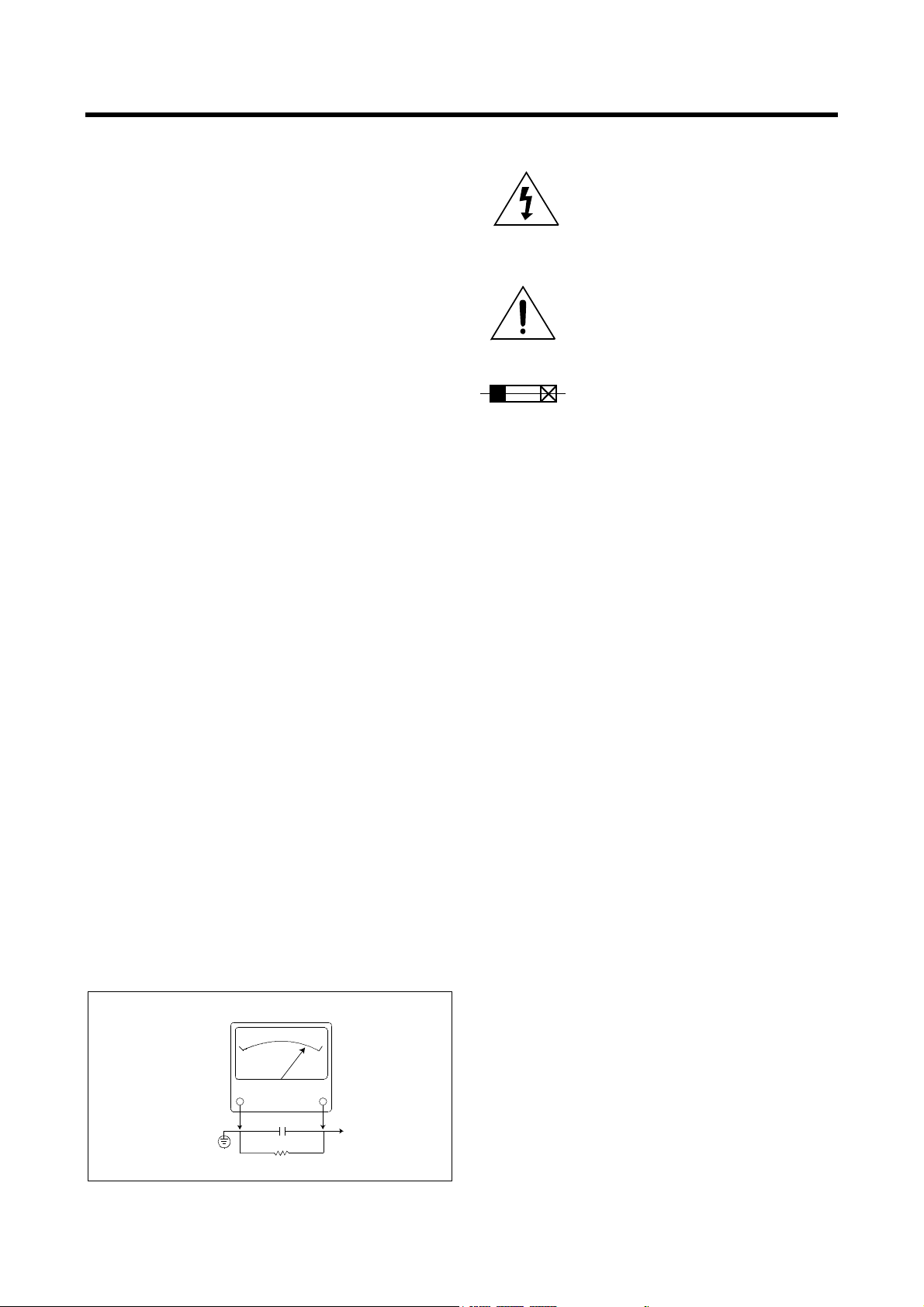
A.C. VOLTMETER
GRAPHIC SYMBOLS :
The lightning flash with arrowhead symbol,
within an equilateral triangle, is intended to alert
the service personnel to the presence of uninsulated “dangerous voltage” that may be of sufficienty magnitude to constitute a risk of electric
shock.
The exclamation point within an equilateral triangle is intended to alert the service personnel
to the presence of important safety information
in service literature.
Fuse symbol is printed on pcb adjacent to the
fuse, with “RISK OF FIRE REPLACE FUSE AS
MARKED”. The symbol is explained in the service manual with the following wording or equivalent.
“CAUTION :
FOR CONTINUED PROTECTION AGAINST FIRE
HAZARD, REPLACE ONLY WITH SAME TYPE (4A, 125V)” and
“
ATTENTION
: AFIN D’ASSU UNE PROTECTION PERMANENTE
CONTRE LES RISQUES D’INCENDIE, REMPLACER UNIQUEMENT PAR UN FUSIBLE DE MEME TYPE ET DE ”4A, 125V”.
SUBJECT : X-RADIATION
1. Be sure procedures and instructions to all service personnel cover
the subject of X-rays in current T.V. receivers is the picture tube.
However, this tube does not emit X-rays when the high voltage is
at the factory specified level. The proper value is given in the applicable schematic. Operation at higher voltages may cause a failure
of the picture tube or high voltage supply and, under certain circumstances, may produce radiation in excess of desirable levels.
2. Only factory specified C.R.T. anode connectors must be used.
Degaussing shields also serve as X-ray shield in color sets.
Always re-install them.
3. It is essential that the serviceman has available an accurate and
reliable high voltage meter. The calibration of the meter should be
checked perio - dically against a reference standard. Such as the
one available at your distributor.
4. When the high voltage circuitry is operating properly there is no
possibility of an X-radiation problem. Every time a color chassis is
serviced, the brightness should be run up and down while monitoring the high voltage with a meter to be certain that the high voltage
does not exceed the specified value and that it is regulating correctly. We suggest that you and your service organization review
test procedures so that voltage regulation is always checked as a
standard servicing procedure. And that the high voltage reading be
recorded on each customer’s invoice.
5. When troubleshooting and making test measurements in a receiver
with a problem of excessive high voltage, avoid being unnecessarily
close to the picture tub eand the high voltage compartment.
Do not operate the chassis longer than is necessary to locate the
cause of excessive voltage.
6. Refer to HV, B+and Shutdown adjustment procedures described in
the appropriate schematic and diagrams(where used).
Good earth ground,
such as the water
pipe, conduit, etc.
0.15 uF
1500 OHM
10WATT
Place this probe
on each exposed
metal part.
3

SUBJECT : IMPLOSION
1. All direct viewed picture tubes are equipped with an integral implosion protection system, but care should be taken to avoid damage
during installation. Avoid scratching the tube. If scratched, replace
it.
2. Use only recommended factory replacement tubes.
SUBJECT : TIPS ON PROPER INSTALLATION
1. Never install any receiver in closed-in recess, cubbyhole or closely
fitting shelf space over, or close to heat duct, or in the path of
heated air flow.
2. Avoid conditions of high humidity such as : Outdoor patio installations where dew is a factor. Near steam radiators where steam
leakage is a factor, etc.
3. Avoid placement where draperies may obstruct rear venting. The
customer should also avoid the use of decorative scarves or other
coverings which might obstruct ventilation.
4. Wall and shelf mounted installations using a commercial mounting
kit, must follow the factory approved mounting instructions. A
receiver mounted to a shelf or platform must retain its original
feet(or the equivalent thickness in spacers) to provide adequate
are flow across the bottom, bolts or screws used for fasteners
must not touch and parts or wiring. Perform leakage test on customized installations.
5. Caution customers against the mounting of a receiver on sloping
shelf or a tilted position, unless the receiver is properly secured.
6. A receiver on a roll-about cart should be stable on its mounting to
the cart. Caution the customer on the hazards of trying to roll a cart
with small casters across thresholds or deep pile carpets.
7. Caution customers against the use of a cart or stand which has not
been listed by underwriters laboratories, inc. For use with their
specific model of television receiver or generically approved for
use with T.V.’s of the same or larger screen size.
4
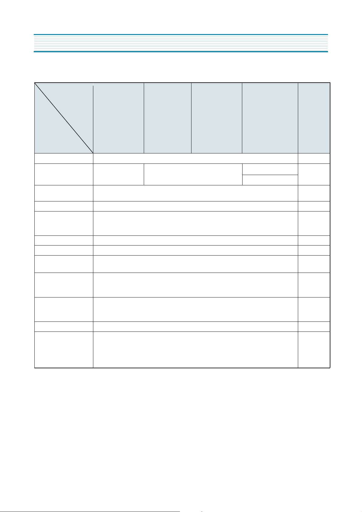
SPECIFICATIONS
DTQ-14P2/P3FCM
DTQ-14P2/V1FCWM/P2SCM
MODEL
ITEMS
TV STANDARD NTSC-M
POWER INPUT
POWER CONSUMPTION
TUNING SYSTEM Frequency Synthesizer ( FS ) Tuning System
TUNING RANGES
SOUND OUTPUT 1.3 W (14/20U1 Series/20V8 Series 1.3W + 1.3W)
SPEAKER 3 W 8 ohm
ANTENNA INPUT
IMPEDANCE
AUXILIARY
INPUT TERMINAL
DTQ-14V1/V5FCM/V1/V4SCM
DTQ-14V5FCNM/15U5SCM
DTQ-14V6FCBM/FCPM/FBBM/FPPM
DTQ-14J4FCGM/FCCM
DTQ-20V1/V4/V5FCM
DTQ-20V1/V4SCM
DTQ-20P2/P3FCM/P2SCM
DTQ-14V6NBM/NPM
DTQ-14V1/V3/V5FSM
DTQ-14V1/V3/V4/V5/V8/V9SSM
DTQ-14U1FSM/SSM/20U1FSM/SSM
DTQ-20P2SSM/15U5FSM
DTQ-20V1/V3/V4FSM
DTQ-20V1/V3/V4/V8/V9SSM
AC 120V 60 Hz
DTQ-14V1/V4/V5FSPM
DTQ-14V1/V4/V5/U1SSPM
DTQ-14V6NBPM/NPPM
DTQ-20V1/V4FSPM
DTQ-20V1/V3/V4/U1SSPM
DTQ-15U5SSPM
AC 220V 50/60 Hz
14 = 55W
20 = 68W
VHF : 2 ~ 13 (12)
UHF : 14 ~ 69 (56)
CATV : 1 ~ 125 (125)
75 ohm Unbalanced
Front : Video, Audio
Rear : Video, Audio
"P" Series Without Video, Audio
DTQ-14V1/V4SSFM
DTQ-20V1/V4SSFM
DTQ-14V4/20V4FCFM
AC60-180V(SSFM Series)
AC90-250V(FCFM Series)
REMARKS
INTERMEDIATE
FREQUENCIES
Picture IF Carrier Frequency : 45.75 MHz
Sound IF Carrier Frequency : 41.25 MHz
Color Sub-Carrier Frequency : 3.579545 MHz
REMOTE CONTROL R-43A08
3-Language OSD
With CAPTION
SPECIAL FUNCTIONS
Wake-up On/Off Time
Sleep Timer
Power Restore
5
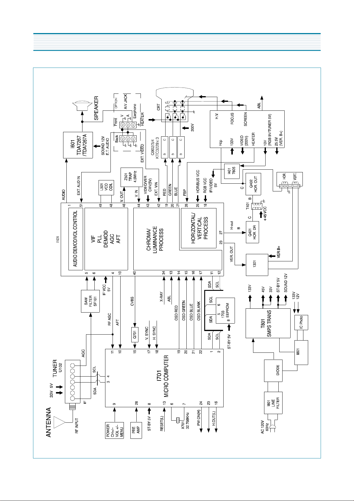
BLOCK DIAGRAM
#2
5
LA78041
Coupler
I805/I806
MR2520
D881~
D884
A.MUTE(H)
6
ALIGNMENT INSTRUCTIONS
1. SERVICE MODE ADJUSTMENTS
Follow the steps below whenever service adjustment is required. See Table- A and Table- B to determine if
service adjustments are required.
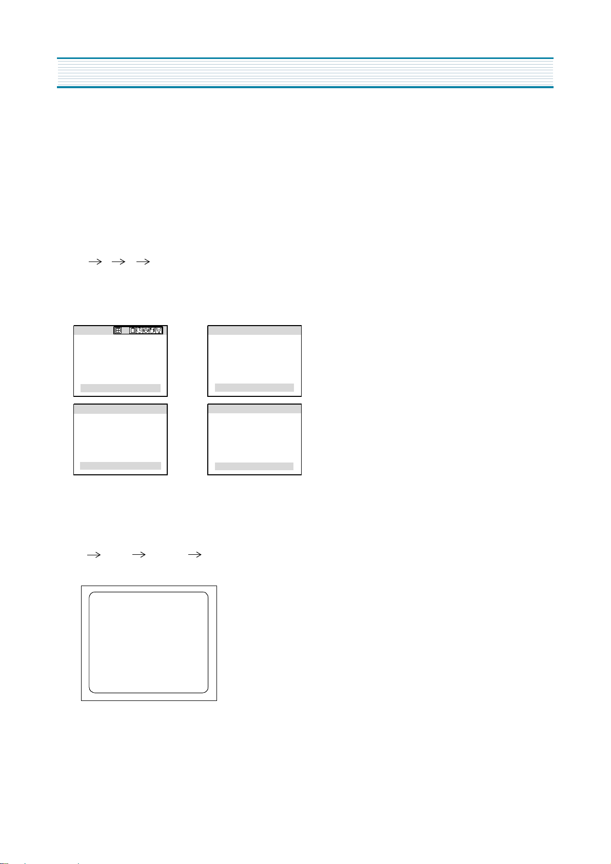
1) How to enter the service mode using the user remote control.
•
Turn the set on.
•
Direct the remote control to the reception window of TV.
•
Push buttons of remote control in sequence as follows.
1 → MUTE → DISPLAY → MUTE
•
Then, the screen will appear as follows.
S2 SCRN
S5 IFC
S6 GEO
S8 W/B
S9 DP
S12 FACT
S7 PTRN NORMAL
•
Using the channel up or channel down button, select the item you wish to adjust.
(The color of selected item turns into the red.)
•
Press the volume up or down button to enter in the service mode you wish to adjust.
2) How to memorize the adjusted values in the service mode.
•
Must press
DISPLAY
button the state which the screen is displaying each of service
after all adjustments are completed each of all service menu.
Table-A : Adjust the values of service mode when a part is replaced.
PART
REPLACED
I701
(U-COM)
I101
(MAIN)
I703
(EEPROM)
NECESSARY UNNECESSARY
ADJUSTMENT
O
O
O
Data is stored in I703.
Initial setting values are written from I701.
Adjusting Items
S5 RFAGCD
S6 H.PHASE/V.POSI/V.SIZE
S8 RD/BD/RB/GB/BB
S9 Subbrightness
menus
NOTES
CRT O Adjust items related to picture tube only.(White Balance adjustment)
7
8
ALIGNMENT INSTRUCTIONS
Table-B
*
indicates the items with different settings each of sets
MODE ADJUSTMENT ITEMS
DATA
REMARKS
INITIAL RANGE
S2 Screen Adjustment - -
S5
Auto RF AGC - -
Video Level (VIDEOL) 7 0 ~ 7 Must be set to 7
RF AGC Delay (RFAGCD) * 0 ~ 63 Align RF AGC threshold
FM Level (FM.LEV) 8 0 ~ 31 Must be set to 30
AGC Point 3.75 - Select AGC reference voltage
A/D VALUE - -
S6
Horizontal Phase(H.PHASE) * 0 ~ 31 Align sync to flyback pulse, using internal cross pattern(S7)
Vertical Position (V.POSI) * 0 ~ 63 Align vertical DC bias, using internal cross pattern(S7)
Vertical Size (V.SIZE) * 0 ~ 127 Align vertical amplitude, using internal cross pattern(S7)
NO SD POWER OFF YES - Automatically turn off in 15min for no received signal.
Vertical S-Correction (V SC) 0 0 ~ 31 Must be set to 7
Vertical Linearity (V LIN) 18 0 ~ 31 Must be set to 18
S7
Internal Black - - Display internal BLACK pattern
Internal 100% White - - Display internal 100% WHITE
Internal 60% White - - Display internal 60% WHITE
Internal Cross Pattern - - Display internal CROSS pattern
S8
Red Drive (RD) * 0 ~ 127 Align RED OUT AC level
Green Drive (GD) 10 0 ~ 15 Must be set to 10
Blue Drive (BD) * 0 ~ 127 Align BLUE OUT AC level
Red Bias (RB) * 0 ~ 255 Align RED OUT DC level
Green Bias (GB) * 0 ~ 255 Align GREEN OUT DC level
Blue Bias (BB) * 0 ~ 255 Align BLUE OUT DC level
S9
S11
Subbrightness * 0 ~ 127 Align common RGB DC level
Must be set to 20
Must be set to 32
Must be set to 32
Must be set to 20
Contrast 10 0 ~ 27
Tint 27 0 ~ 77
Color
Sharp
RGDEF
BGSLC
HBR
HBL
GYAng
CkOPE
WPL
PREADJ
Dcrest
BLKSTR
BLKGAN
Hout On
Hout of
1
3
1
6
1
1
0
0
3
3
3
3
3
0,1
0~3
0~7
0~7
0,1
0~7
0,1
0~3
0~3
0~3
0~3
0~31
0~31
15
30
0 ~ 47
0 ~ 30
S12 Forwarding Mode - Factory Initialization

9
2) FOCUS ADJUSTMENT
•
Turn in a local station and adjust the Focus Control knob (located on FBT) for best picture
details at high light condition.
3) RF AGC DELAY ADJUSTMENT (S5)
•
Receive a good local channel.
•
Enter the service mode and select service adjustment S5.
•
You can see the OSD as shown in below.
•
Select RFAGCD item, press the volume up or down button until noise or beat in picture disappears.
•
Press the DISPLAY button to memorize the data.
IF CONTROL
AUTO RFAGC START
VIDEOL 7
RFAGCD 10
FM.LEV 30
AGC POINT 3.75
MOVE ADJUST RECALL : SET
2. ASSEMBLY ADJUSTMENTS
1) SCREEN ADJUSTMENT (S2)
•
Enter the service mode and select service adjustment S2.
•
You cna see the one horizontal line on the screen.
•
Adjust the Screen Control Volume (located on FBT) so that the horizontal line onscreen may be
disappeared.
•
Press the volume up or down button to exit in the screen adjustment mode.
IN THE SCREEN ADJUSTMENT MODE, DONT PRESS OTHER BUTTONS EXCEPT VOLUME UP OR DOWN BUTTON.
NOTE
ALIGNMENT INSTRUCTIONS
10
ALIGNMENT INSTRUCTIONS
4-3. Vertical Size Adjustment
•
Select “V.SIZE” item, adjust “V.SIZE” data value to proper vertical size as follows.
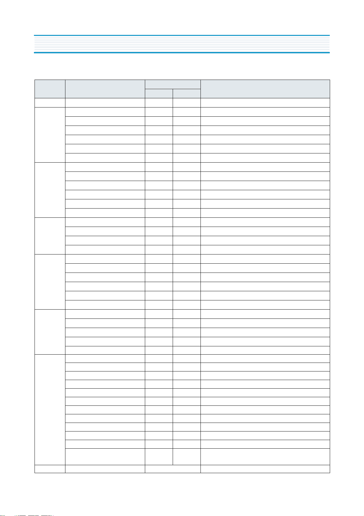
4) GEOMETRIC ADJUSTMENTS (S6)
•
Enter the service mode and select service adjustment S7.
•
Whenever you select the “S7” using the volume up or down button, the screen is changing like this.
•
Using the volume up or down button, select internal cross pattern.
•
Select service adjustment S6
•
You can see the OSD as shown in below.
4-1. Horizontal Position Adjustment
•
Select H.PHASE item, adjust H.PHASE data value to obtain proper horizontal centering of the
internal cross pattern at the left and right of the screen.
4-2. Vertical Position Adjustment
•
Select V.POSI item, adjust V.POSI data value to center the raster properly on thescreen.
GEOMETRY
H. PHASE 17
V. POSI 29
V. SIZE 80
NO SD POWER OFF YES
VSC 7
V LIN 18
MOVE ADJUST RECALL : SET
NORMAL BLACK WHITE100 WHITE60 CROSS
11
ALIGNMENT INSTRUCTIONS
•
Select Subbrightness item, adjust Subbrightness data value
to obtain normal
brightness level.
•
Press the DISPLAY button to memorize the data.
CONTRAST
•
Fixed value = 20
TINT
•
Fixed value = 32
COLOR
•
Fixed value = 32
7) FACTORY OUTGOING MODE (S12 : FACT)
•
If you select the S12, then the set becomes factory outgoing status.
•
You can see the OSD “outgoing OK”
6) DIGITAL PRESET(D.P) ADJUSTMENTS(S9)
SUBBRIGHTNESS ADJUSTMENT
•
Receive a good local channel.
•
Enter the service mode and select service adjustment S9.
•
You can see the OSD as shoown in below.
D.P.
SUB BRIGHTNESS 64
CONTRAST 20
TINT 32
COLOR 32
MOVE ADJUST RECALL : SET
5) WHITE BALANCE ADJUSTMENT(S8)
•
Receive a good local channel.
•
Enter the service mode and select service adjustment S8.
•
You can see the OSD as shown in below.
•
Using volume up or volume down, adjust service adjustment data of RD/GD/BD and RB/GB/BB until a good gray
scale with normal whites is obtained.ALIGNMENT INSTRUCTIONS
•
Press the DISPLAY button to memorize the data.
RD 58
GD 10
BD 65
RB 105
GB 127
BB 100
MOVE ADJUST RECALL : SET
ALIGNMENT INSTRUCTIONS
3. PARENTAL CONTROL PASSWORD SETTINGS
If user forget Parental Control Password as follows.
1) CHANGE THE PASSWORD.
• Turn the set on.
• Direct the remote control to the reception window of your TV/VCR
• Using the MENU buttons, select the Special menu.
¡ã
• Using the the channel up (
• Using the volume up (
• Push buttons of remote control in sequence as follows.
2 2 1 1
• Parental control password is reset.
• Using the 0~9 buttons, enter the password.
• Using the 0~9 buttons, repeat the password.
) or down ( ¡å ) duttons, select prental control.
¢º
), set the password Menu.
Special
Closed Caption : OFF
CC on Mute : OFF
Power Restore : OFF
Parental Control
Select Enter n Exit
Parental control
Enter New Password
[0 - 9] : Adjust
n
Exit
Parental control
Enter the Password
[0 - 9] : Adjust
Parental control
Repeat the Password
[0 - 9] : Adjust
# # # #
# # # #
n
Exit
n
Exit
2) RESET THE PASSWORD
• Turn the set on.
• Direct the remote control to the reception window of your TV/VCR.
• Push buttons of remote control in sequence as follows.
1 MUTE DISPLAY MUTE
• Then, the screen will appear as follows.
FIELE SVC
S2 SCRN V.=02h RCCR=00h
S5 IFC
S6 GEO
S8 W/B
S9 DP
S12 FACT
S7 PTRN NORMAL
¢º S10 SOUND
¡ã
• Using the channel up (
Press the volume up (
) or down ( ¡å ) buttons, select S12 FACT.
¢º
) button, the set becomes factory outgoing status.
• Parental control password is reset.
• Using the MENU buttons, select the parental control menu, set the new password.
12
VOLTAGE CHART
13
LOC PIN
MODE
LOC PIN
MODE
ON OFF ON OFF
I501 1 2.17 0 44 2.63 0
2 1.95 0 45 2.39 0
3 2.7 0 46 2.16 0
4 2.39 0.49 47 3.62 0
5 2.86 0 48 4.23 0.51
6 2.86 0 49 4.23 0.51
7 0 0 50 2.3 0
8 4.87 0.57 51 2.19 0.65
9 1.76 0 52 1.99 0.32
10 2.46 0.28 53 2.39 0
11 4.9 4.93 54 3.08 0.3
12 4.86 4.92
LOC PIN
MODE
13 3.59 0 ON OFF
14 1.38 0 I301 1 2.21 0
15 1.39 0 2 25.7 0
16 1.39 0 3 2.27 3.63
17 0 0 4 0 0
18 8.11 0.235 5 13.65 0
19 2.61 0.232 6 26.2 0.43
20 2.57 0 7 2.21 0
21 2.71 0
LOC PIN
MODE
22 NC NC ON OFF
23 2.27 0 I401 1 7.66 0
24 2.59 0 2 0 0
25 5.12 4.23 3 4.95 0.6
26 2.62 2.2
LOC PIN
MODE
27 0.94 0.16 ON OFF
28 0.86 1.37 I601 1 12.09 7.19
29 1.69 1.4 2 6.2 0
30 4.96 0.706 3 6.5 0
31 0 0 4 0.824 0
32 2.73 0.31 5 0 0
33 0 0 6 0 0
34 0 0 7 0 0
35 2.37 0 8 0 0
36 3.38 0 9 0 0
37 1.72 0 10 0 0
38 2.77 0.35 11 0 0
39 5.09 0 12 0 0
40 2.12 0 13 0 0
41 0 0 14 0 0
42 2.45 0 15 0 0
43 4.84 0.5 16 0 0
VOLTAGE CHART
14
LOC PIN
MODE
LOC PIN
MODE
ON OFF ON OFF
I701 1 4.86 4.96 I703 1 0 0
2 4.81 4.94 2 0 0
3 5.03 4.97 3 0 0
4 5.03 4.97 4 0 0
5 0 0 5 4.91 4.94
6 1.9 1.87 6 4.86 4.92
7 2.71 2.67 7 0 0
8 4.99 4.91 8 5.01 4.95
9 5.04 4.95
LOC PIN
MODE
10 0 0 ON OFF
11 2.28 0 I801 1 2.47 0
12 0 4.88 2 2.33 1.33
13 4.93 4.87 3 0 0
14 3.71 3.64 4 18.28 9.19
15 2.66 2.44 5 137.2 145
16 0 4.88 6 0.067 0
17 4.96 0.71 7 137.2 145
18 4.07 4.95
19 0 0
20 0 0
21 0 0
22 0 0
23 4.84 4.56
24 0 0
25 0 0
26 0 0
27 0 0.22
28 5.03 4.93
29 4.8 4.7
30 5.05 4.95
31 0 4.88
32 5.05 4.95
33 0 0
34 0 0
35 0 0
36 0 0

VOLTAGE CHART
15
LOC PIN
MODE
LOC PIN
MODE
ON OFF ON OFF
Q201 C 5.03 4.95 Q703 C 5.04 4.17
E 3.29 3.26 E 0.44 0
B 2.51 2.47 B 1.06 0
Q401 C -3.63 35.55 Q704 C 5 4.92
E 0 0 E 4.97 4.89
B 0.35 0 B 4.35 4.28
Q402 C 130.2 102.3 Q707 C 5.05 4.98
E 0 0 E 0.18 4.19
B 0 0 B 0.06 4.89
Q404 C 10.23 0 Q804 C 0 0
E 0 0 E 132.6 102.2
B 0 0 B 132.2 102.2
Q501 C 0 0 Q805 C 12.12 7.19
E 3.59 0 E 5.03 4.96
B 4.53 0 B 5.63 5.59
Q575 C -0.1 0 Q806 C 5.13 0
E 10 0 E 5.05 4.98
B 10.22 0 B 4.46 5.45
Q653 C 6.52 0 Q871 C 12.09 0.03
E00 E00
B 0 0.71 B 0.04 0.7
Q701 C 4.07 4.96 Q873 C 0.04 5.45
E00 E00
B 0 0 B 0.68 0

WAVEFORMS
16
(1) I101 PIN 19
V:1V/div
H:25us/div
(2) I101 PIN 20
V:1V/div
H:25us/div
(3) I101 PIN 21
V:1V/div
H:25us/div
(4) I101 PIN 23
V:500mV/div
H:5ms/div
(5) I101 PIN 40
V:500mV/div
H:25us/div
(6) I101 PIN 44
V:500mV/div
H:25us/div
(7) I101 PIN 46
V:500mV/div
H:25us/div
(8) I101 PIN 6
V:10V/div
H:5ms/div

WAVEFORMS
17
(9) I701 PIN 7
V:1V/div
H:50us/div
(10) I101 PIN 17
V:2V/div
H:25us/div
(11) I701 PIN 18
V:20V/div
H:25us/div
(12) I801 PIN 7
V:100V/div
H:10us/div
(13) T402 PIN 25.5V
V:100V/div
H:25us/div
(14) T402 PIN 10.5V
V:50V/div
H:25us/div
(15) T402 PIN HEATER
V:10V/div
H:25us/div
(16) T402 PIN 200V
V:100V/div
H:25us/div

WAVEFORMS
18
(17) T401 PIN H.V
V:100V/div
H:25us/div
(18) T801 PIN 133V
V:100V/div
H:10us/div
(19) Q401 COLLECTOR
V:5V/div
H:25us/div
(20) CRT SOCKET PIN B
V:50V/div
H:25us/div
(21) CRT SOCKET PIN R
V:50V/div
H:25us/div
(22) CRT SOCKET PIN G
V:50V/div
H:25us/div

SCHEMATIC DIAGRAM
19

EXPLODED VIEW
1. DTQ-14V1FSM
20

2. DTQ-14V3FSM
EXPLODED VIEW
21

22
EXPLODED VIEW
3. DTQ-14V5FCM / FSM

23
EXPLODED VIEW
4. DTQ-14U1FSM

24
EXPLODED VIEW
5. DTQ-20V1FSM

25
EXPLODED VIEW
6. DTQ-20V3FSM

26
EXPLODED VIEW
7. DTQ-20V4FSM

27
EXPLODED VIEW
8. DTQ-20U1FSM

28
z_loc z_parts_code parts_name parts_descr remark
ZZ100 48B4343A08 TRANSMITTER REMOCON R-43A08 (AA)
ZZ110 PTACPWH394 ACCESSORY AS DTQ-14P2FC
00010 4850A02510 ANT ROD S3BW216B (L=600 MM)
00030 4850Q00810 BATTERY R6P/LN
00040 4850A00250 TRANS ANT MATCHING IMT-06
10000 48586001E2 MANUAL INSTRUCTION DTQ-20V1FS
M821 4858213800 BAG INSTRUCTION L.D.P.E T0.05X250X400
ZZ120 PTBCSHH567 COVER BACK AS DTQ-14V1FCM
M211 4852151400 COVER BACK FR HIPS BK
M211B 4857817640 CLOTH BLACK FELT 100X20X0.7
ZZ130 PTPKCPH567 PACKING AS DTQ-14V1FCM
10 6520010100 STAPLE PIN AUTO W65
M801 485803871D BOX CARTON SW-2
M811 4858186700 PAD EPS 14V1
M821 4858215700 BAG PE PE FOAM t0.5x1000X950
ZZ131 58G0000078 COIL DEGAUSSING DC-1400
ZZ132 48519A4710 CRT GROUND NET 1401S-1015-1P
ZZ140 PTCACAH567 CABINET AS DTQ-14V1FCM
CRT1 PTRTPWH394 CRT AS “NTSC 14”” ITC CRT AS”
V01 58D0000082 COIL DY ODY-M1489
V04 2224050026 BOND SILICON RTV 122 CARTRIDGE
V05 4850PM001- MAGNET CP NY-225 (MINI NECK)
V06 48A96R004- RUBBER WEDGE HMR 28 SR (/0X54)
V901 48A96314C3 CRT BARE A34KQV42X
M201A 4856013350 SCREW CRT FIXING 25X80 BK
M201B 4856215402 WASHER RUBBER CR T2.0
M211A 7172401412 SCREW TAPPTITE TT2 TRS 4X14 MFZN BK
M541 4855415800 SPEC PLATE 150ART P/E FILM (C/TV)
M601 4856013351 SCREW CRT FIXING 25X140 YL
M681 4856812001 TIE CABLE NYLON66 DA100
SP01A 7178301011 SCREW TAPPTITE TT2 WAS 3X10 MFZN
ZZ200 PTFMSJH567 MASK FRONT AS DTQ-14V1FCM
M191 4851931800 BUTTON CTRL 4939100+5536001
M191A 7178301011 SCREW TAPPTITE TT2 WAS 3X10 MFZN
M201 4852067200 MASK FRONT FR HIPS BK
M321 4853214800 BRKT FR HIPS BK
M561 4855613600 MARK BRAND COPPER T0.4
ZZ202 PTSPPWH407 SPEAKER AS DTQ-14J4FC
PA601 4850703S50 CONNECTOR YH025-03+35098+ULW=200
SP01 4858314010 SPEAKER SP-5070F01 3W 8 OHM
ZZ290 PTMPMSH567 PCB MAIN MANUAL AS DTQ-14V1FCM
10 2193102005 SOLDER BAR SN:PB=63:47 S63S-1320
30 2291050616 FLUX SOLDER JS-64T3
40 2291050301 FLUX SOLVENT IM-1000
C404 CMYH3C722H C MYLAR 1.6KV BUP 7200PF H
z_loc z_parts_code parts_name parts_descr remark
C406 CMYE2D434J C MYLAR 200V PU 0.43MF J
C801 CL1UC3104M C LINE ACROSS WORLD AC250V 0.1UF M R.47
C804 CEYN2D331P C ELECTRO 200V LHS 330MF
D703 DLH2PR—— LED BLOCK LH-2P-R
I101 1LA76845N- IC LA76845N
I301 PTD2SW7100 HEAT SINK ASS`Y 1LA78041— + 7174300811
00001 1LA78041— IC VERTICAL LA78041
0000A 4857027100 HEAT SINK SPCC T1.0+SN
0000B 7174300811 SCREW TAPPTITE TT2 RND 3X8 MFZN
I401 1K1A7805P1 IC REGULATOR KIA7805API
I601 1TDA7267— IC AUDIO AMP TDA7267
I701 1DW8634NA3 IC MICOM DW863432W-NA3(50C5)
I703 124LC04B— IC MEMORY 24LC04B
I801 1MR2520—- IC POWER MR2520
I805 1LTV817C— IC PHOTO COUPLER LTV-817C
I806 1LTV817C— IC PHOTO COUPLER LTV-817C
IL701 1356VF6—- IC PREAMP 356VF6
JP02 4859109950 JACK PIN BOARD PH-JB-9710A
JP03 4859109150 JACK PIN BOARD PH-JB-9615C
L501 58N0000042 COIL VCO TRF-V008
L801 5PLF24A1— FILTER LINE LF-24A1
M681 4856812001 TIE CABLE NYLON66 DA100
P401 4859240020 CONN WAFER YFW500-05
P501 4850708N11 CONNECTOR BIC-08T-25T+C-20T+ULW=300
PWC1 4859907910 CORD POWER AS ME301P+TER=1830
Q402 PTA2SW7201 HEAT SINK ASS`Y T2SD2627YB + 7174300811
00001 T2SD2627YB TR 2SD2627LS-YB
0000A 4857027201 HEAT SINK AL T1.0
0000B 7174300811 SCREW TAPPTITE TT2 RND 3X8 MFZN
R801 RX07B229JP R CEMENT 7W 2.2 OHM J BEN 15MM 4P
RLY1 5SC0101338 SW RELAY DQ5D1-O(M)/GJ-SS-105LM
RS801 DSVC471D14 VARISTOR SVC471D14A
SCT1 4859303930 SOCKET CRT ISMG03S INCHANG
SF101 5PTSF5241P FILTER SAW TSF5241P
T401 50D10A3—- TRANS DRIVE TD-10A3
T402 50H0000241 FBT FSA37023M
T801 50M3541T8- TRANS SMPS TSM-3541T8
U102 4859721730 TUNER VARACTOR DT5-NF20F N
X701 5XYR03276C CRYSTAL QUARTZ C-001R 32.768000KHZ 20PPM
Z501 5PYXT4R5MB FILTER CERA XT 4.5MB
ZZ200 PTMPJ2H567 PCB CHIP MOUNT B AS DTQ-14V1FCM
JC568 HRFS000-BA R CHIP 1/16 0 OHM 1608
JC701 HRFS000-BA R CHIP 1/16 0 OHM 1608
JC702 HRFS000-BA R CHIP 1/16 0 OHM 1608
JC703 HRFS000-BA R CHIP 1/16 0 OHM 1608
" " is a safety patt, so it must be used the same part.
" " is a recommendable part for essential stock.
R
ELECTRICAL PARTS LIST
✐ CAUTION : In this Service Manual, some parts can be changed for improving their
performance without notice in the parts list. So, if you need the latest parts
information, please refer to PPL(Parts Price List)in Service information
Center(http://svc.dwe.co.kr)

z_loc z_parts_code parts_name parts_descr remark
JC704 HRFS000-BA R CHIP 1/16 0 OHM 1608
RC150 HRFS153JBA R CHIP 1/16 15K OHM J 1608
RC151 HRFS104JBA R CHIP 1/16 100K OHM J 1608
RC154 HRFS473JBA R CHIP 1/16 47K OHM J 1608
RC156 HRFS473JBA R CHIP 1/16 47K OHM J 1608
RC165 HRFS472JBA R CHIP 1/16 4.7K OHM J 1608
RC223 HRFS224JBA R CHIP 1/16 220K OHM J 1608
RC224 HRFS224JBA R CHIP 1/16 220K OHM J 1608
RC225 HRFS392JBA R CHIP 1/16 3.9K OHM J 1608
RC226 HRFS101JBA R CHIP 1/16 100 OHM J 1608
RC227 HRFS102JBA R CHIP 1/16 1K OHM J 1608
RC228 HRFS103JBA R CHIP 1/16 10K OHM J 1608
RC229 HRFS750JBA R CHIP 1/16 75 OHM J 1608
RC508 HRFS102JBA R CHIP 1/16 1K OHM J 1608
RC509 HRFS102JBA R CHIP 1/16 1K OHM J 1608
RC510 HRFS331JBA R CHIP 1/16 330 OHM J 1608
RC511 HRFS123JBA R CHIP 1/16 12K OHM J 1608
RC525 HRFS102JBA R CHIP 1/16 1K OHM J 1608
RC526 HRFS132JBA R CHIP 1/16 1.3K OHM J 1608
RC530 HRFS561JBA R CHIP 1/16 560 OHM J 1608
RC531 HRFS561JBA R CHIP 1/16 560 OHM J 1608
RC533 HRFS390JBA R CHIP 1/16 39 OHM J 1608
RC554 HRFS514JBA R CHIP 1/16 510K OHM J 1608
RC557 HRFS302JBA R CHIP 1/16 3K OHM J 1608
RC558 HRFS103JBA R CHIP 1/16 10K OHM J 1608
RC559 HRFS331JBA R CHIP 1/16 330 OHM J 1608
RC561 HRFS301JBA R CHIP 1/16 300 OHM J 1608
RC562 HRFS824JBA R CHIP 1/16 820K J 1608
RC565 HRFS123JBA R CHIP 1/16 12K OHM J 1608
RC566 HRFS123JBA R CHIP 1/16 12K OHM J 1608
RC567 HRFS103JBA R CHIP 1/16 10K OHM J 1608
RC568 HRFS472FBA R CHIP 1/16 4.7K OHM F 1608
RC569 HRFS152JBA R CHIP 1/16 1.5K OHM J 1608
RC570 HRFS103JBA R CHIP 1/16 10K OHM J 1608
RC629 HRFS102JBA R CHIP 1/16 1K OHM J 1608
RC630 HRFS104JBA R CHIP 1/16 100K OHM J 1608
RC655 HRFS162JBA R CHIP 1/16 1.6K OHM J 1608
RC703 HRFS101JBA R CHIP 1/16 100 OHM J 1608
RC709 HRFS392JBA R CHIP 1/16 3.9K OHM J 1608
RC732 HRFS102JBA R CHIP 1/16 1K OHM J 1608
RC733 HRFS102JBA R CHIP 1/16 1K OHM J 1608
RC734 HRFS102JBA R CHIP 1/16 1K OHM J 1608
RC735 HRFS102JBA R CHIP 1/16 1K OHM J 1608
RC736 HRFS103JBA R CHIP 1/16 10K OHM J 1608
RC737 HRFS103JBA R CHIP 1/16 10K OHM J 1608
RC738 HRFS471JBA R CHIP 1/16 470 OHM J 1608
RC740 HRFS102JBA R CHIP 1/16 1K OHM J 1608
RC741 HRFS000-BA R CHIP 1/16 0 OHM 1608
RC743 HRFS472JBA R CHIP 1/16 4.7K OHM J 1608
RC744 HRFS242JBA R CHIP 1/16 2.4K OHM J 1608
RC746 HRFS752JBA R CHIP 1/16 7.5K OHM J 1608
RC747 HRFS243JBA R CHIP 1/16 24K OHM J 1608
RC751 HRFS471JBA R CHIP 1/16 470 OHM J 1608
29
z_loc z_parts_code parts_name parts_descr
RC752 HRFS471JBA R CHIP 1/16 470 OHM J 1608
RC755 HRFS102JBA R CHIP 1/16 1K OHM J 1608
RC756 HRFS102JBA R CHIP 1/16 1K OHM J 1608
RC763 HRFS201JBA R CHIP 1/16 200 OHM J 1608
RC775 HRFS472JBA R CHIP 1/16 4.7K OHM J 1608
RC778 HRFS103JBA R CHIP 1/16 10K OHM J 1608
RC779 HRFS472JBA R CHIP 1/16 4.7K OHM J 1608
RC781 HRFS102JBA R CHIP 1/16 1K OHM J 1608
RC782 HRFS331JBA R CHIP 1/16 330 OHM J 1608
RC783 HRFS472JBA R CHIP 1/16 4.7K OHM J 1608
RC784 HRFS514JBA R CHIP 1/16 510K OHM J 1608
RC785 HRFS000-BA R CHIP 1/16 0 OHM 1608
RC786 HRFS102JBA R CHIP 1/16 1K OHM J 1608
RC787 HRFS472JBA R CHIP 1/16 4.7K OHM J 1608
RC788 HRFS472JBA R CHIP 1/16 4.7K OHM J 1608
RC791 HRFS102JBA R CHIP 1/16 1K OHM J 1608
RC792 HRFS102JBA R CHIP 1/16 1K OHM J 1608
RC793 HRFS102JBA R CHIP 1/16 1K OHM J 1608
RC794 HRFS102JBA R CHIP 1/16 1K OHM J 1608
RC797 HRFS103JBA R CHIP 1/16 10K OHM J 1608
RC799 HRFS103JBA R CHIP 1/16 10K OHM J 1608
RC917 HRFS241JBA R CHIP 1/16 240 OHM J 1608
RC918 HRFS241JBA R CHIP 1/16 240 OHM J 1608
RC919 HRFS241JBA R CHIP 1/16 240 OHM J 1608
RC923 HRFS471JBA R CHIP 1/16 470 OHM J 1608
RC924 HRFS471JBA R CHIP 1/16 470 OHM J 1608
RC925 HRFS471JBA R CHIP 1/16 470 OHM J 1608
RC933 HRFS471JBA R CHIP 1/16 470 OHM J 1608
RC934 HRFS471JBA R CHIP 1/16 470 OHM J 1608
RC935 HRFS471JBA R CHIP 1/16 470 OHM J 1608
RC977 HRFS201JBA R CHIP 1/16 200 OHM J 1608
ZZ200 PTMPJ0H567 PCB MAIN (RHU) AS DTQ-14V1FCM
C105 CEXF1C471V C ELECTRO 16V RSS 470MF (8X12)TP
C310 CEXF1E102V C ELECTRO 25V RSS 1000MF (13X20) TP
C410 CEXF2E100V C ELECTRO 250V RSS 10MF (10X20) TP
C414 CEXF1V471V C ELECTRO 35V RSS 470MF (10X20) TP
C415 CEXF1C102V C ELECTRO 16V RSS 1000MF (10X20) TP
C502 CEXF1C471V C ELECTRO 16V RSS 470MF (8X12)TP
C507 CMXM2A224J C MYLAR 100V 0.22MF J
C508 CMXM2A224J C MYLAR 100V 0.22MF J
C510 CEXF1C471V C ELECTRO 16V RSS 470MF (8X12)TP
C514 CEXF1C471V C ELECTRO 16V RSS 470MF (8X12)TP
C602 CEXF1C102V C ELECTRO 16V RSS 1000MF (10X20) TP
C646 CEXF1C471V C ELECTRO 16V RSS 470MF (8X12)TP
C809 CBXB3D102K C CERA SEMI 2KV BL(N) 1000PF K (T)
C812 CEXF1C102V C ELECTRO 16V RSS 1000MF (10X20) TP
C813 CCXB3A221K C CERA 1KV B 220PF K (TAPPING)
C814 CEXF2C101V C ELECTRO 160V RSS 100MF (16X25) TP
C820 CEXF2C101V C ELECTRO 160V RSS 100MF (16X25) TP
C881 CH1BEE472M C CERA AC U/C/V 2.5KV 4700PF TP
C882 CH1BEE472M C CERA AC U/C/V 2.5KV 4700PF TP
C912 CH1BEE472M C CERA AC U/C/V 2.5KV 4700PF TP
F802 5FUMK4021L FUSE GLASS TUBE UL TL 4.0A 125V CASE
ELECTRICAL PARTS LIST

30
z_loc z_parts_code parts_name parts_descr remark
R881 DDT7R0M140 POSISTOR ECPAC7R0M140
ZZ200 PTMPJBH567 PCB MAIN M-10 AS DTQ-14V1FCM
10 2TM18006BE TAPE MASKING 6.2X500
D401 D1N4937G— DIODE 1N4937G (TAPPING)
D405 D1N4937G— DIODE 1N4937G (TAPPING)
D406 D1N4937G— DIODE 1N4937G (TAPPING)
D407 D1N4937G— DIODE 1N4937G (TAPPING)
D408 D1N4937G— DIODE 1N4937G (TAPPING)
D807 DRGP15J—- DIODE RGP15J
D810 D1N4937G— DIODE 1N4937G (TAPPING)
D811 D1N4937G— DIODE 1N4937G (TAPPING)
D881 DLT2A05G— DIODE LT2A05G (TP)
D882 DLT2A05G— DIODE LT2A05G (TP)
D883 DLT2A05G— DIODE LT2A05G (TP)
D884 DLT2A05G— DIODE LT2A05G (TP)
E001 4856310600 EYE LET BSR T0.2 (R2.3)
E006 4856310600 EYE LET BSR T0.2 (R2.3)
E007 4856310600 EYE LET BSR T0.2 (R2.3)
E008 4856310600 EYE LET BSR T0.2 (R2.3)
E011 4856310300 EYE LET BSR T0.2 (R1.6)
E012 4856310300 EYE LET BSR T0.2 (R1.6)
E013 4856310300 EYE LET BSR T0.2 (R1.6)
E014 4856310300 EYE LET BSR T0.2 (R1.6)
E018 4856310300 EYE LET BSR T0.2 (R1.6)
E020 4856310300 EYE LET BSR T0.2 (R1.6)
E023 4856310300 EYE LET BSR T0.2 (R1.6)
E025 4856310300 EYE LET BSR T0.2 (R1.6)
E030 4856310600 EYE LET BSR T0.2 (R2.3)
E031 4856310600 EYE LET BSR T0.2 (R2.3)
E034 4856310600 EYE LET BSR T0.2 (R2.3)
E036 4856310600 EYE LET BSR T0.2 (R2.3)
E038 4856310600 EYE LET BSR T0.2 (R2.3)
E039 4856310300 EYE LET BSR T0.2 (R1.6)
E040 4856310300 EYE LET BSR T0.2 (R1.6)
E041 4856310300 EYE LET BSR T0.2 (R1.6)
E043 4856310300 EYE LET BSR T0.2 (R1.6)
E044 4856310300 EYE LET BSR T0.2 (R1.6)
E045 4856310300 EYE LET BSR T0.2 (R1.6)
E046 4856310300 EYE LET BSR T0.2 (R1.6)
P601 485923162S CONN WAFER YW025-03 (STICK)
P801A 4857417500 TERM PIN DA-IB0214(D2.3/DY PIN)
P801B 4857417500 TERM PIN DA-IB0214(D2.3/DY PIN)
R601 RF01Z688K- R FUSIBLE 1W 0.68 OHM K (TAPPING)
R805 RS02Z228JS R M-OXIDE FILM 2W 0.22 OHM J SMALL
R814 RS02Z828JS R M-OXIDE FILM 2W 0.82 OHM J SMALL
ZZ200 PTMPJRH567 PCB MAIN RADIAL AS DTQ-14V1FCM
C101 CEXF1H109V C ELECTRO 50V RSS 1MF (5X11) TP
C102 CEXF1C101V C ELECTRO 16V RSS 100MF (6.3X11) TP
C103 CEXF1H339V C ELECTRO 50V RSS 3.3MF (5X11) TP
C104 CMXM2A333J C MYLAR 100V 0.033MF J (TP)
C106 CEXF1H109V C ELECTRO 50V RSS 1MF (5X11) TP
C212 CEXF1H100V C ELECTRO 50V RSS 10MF (5X11) TP
C235 CEXD1H229F C ELECTRO 50V RND 2.2MF (5X11) TP
z_loc z_parts_code parts_name parts_descr remark
C301 CMXM2A103J C MYLAR 100V 0.01MF J (TP)
C302 CEXF1H479V C ELECTRO 50V RSS 4.7MF (5X11) TP
C303 CEXF1H100V C ELECTRO 50V RSS 10MF (5X11) TP
C305 CEXF1H101V C ELECTRO 50V RSS 100MF (8X11.5) TP
C307 CXSL2H100D C CERA 500V SL 10PF D (TAPPING)
C308 CMXM2A104J C MYLAR 100V 0.1MF J (TP)
C311 CEXD1H229Q C ELECTRO 50V RT 2.2MF (6.3X11) TP
C401 CCXB2H102K C CERA 500V B 1000PF K (TAPPING)
C403 CMXM2A103J C MYLAR 100V 0.01MF J (TP)
C405 CEXF2C109V C ELECTRO 160V RSS 1MF (6.3X11) TP
C411 CEXF1H100V C ELECTRO 50V RSS 10MF (5X11) TP
C413 CCXB2H102K C CERA 500V B 1000PF K (TAPPING)
C418 CMXM2A104J C MYLAR 100V 0.1MF J (TP)
C451 CEXF1C101V C ELECTRO 16V RSS 100MF (6.3X11) TP
C452 CEXF1C221V C ELECTRO 16V RSS 220MF (8X11.5) TP
C501 CMXL1J105J C MYLAR 63V MEU 1MF J
C509 CEXF1H109V C ELECTRO 50V RSS 1MF (5X11) TP
C511 CMXM2A333J C MYLAR 100V 0.033MF J (TP)
C512 CEXF1H108V C ELECTRO 50V RSS 0.1MF (5X11) TP
C513 CEXF1H109V C ELECTRO 50V RSS 1MF (5X11) TP
C516 CEXF1H229V C ELECTRO 50V RSS 2.2MF (5X11) TP
C517 CMXM2A473J C MYLAR 100V 0.047MF J (TP)
C518 CEXF1H478V C ELECTRO 50V RSS 0.47MF (5X11) TP
C519 CEXF1H478V C ELECTRO 50V RSS 0.47MF (5X11) TP
C520 CEXF1H109V C ELECTRO 50V RSS 1MF (5X11) TP
C525 CEXF1H109V C ELECTRO 50V RSS 1MF (5X11) TP
C554 CMXM2A153J C MYLAR 100V 0.015MF J (TP)
C556 CXCH1H809D C CERA 50V CH 8PF D (TAPPING)
C576 CEXF1C221V C ELECTRO 16V RSS 220MF (8X11.5) TP
C580 CCXB1H152K C CERA 50V B 1500PF K (TAPPING)
C581 CEXF1H109V C ELECTRO 50V RSS 1MF (5X11) TP
C601 CMXM2A103J C MYLAR 100V 0.01MF J (TP)
C603 CEXF1H108V C ELECTRO 50V RSS 0.1MF (5X11) TP
C604 CEXF1C101V C ELECTRO 16V RSS 100MF (6.3X11) TP
C634 CEXF1H479V C ELECTRO 50V RSS 4.7MF (5X11) TP
C662 CCXF1H153Z C CERA 50V F 0.015MF Z
C701 CEXF1H470V C ELECTRO 50V RSS 47MF (6.3X11) TP
C702 CEXF1C221V C ELECTRO 16V RSS 220MF (8X11.5) TP
C703 CEXF1H109V C ELECTRO 50V RSS 1MF (5X11) TP
C704 CEXF1H229V C ELECTRO 50V RSS 2.2MF (5X11) TP
C705 CEXF1H109V C ELECTRO 50V RSS 1MF (5X11) TP
C757 CCXF1H333Z C CERA 50V F 0.033MF Z (TAPPING)
C807 CEXF1E221V C ELECTRO 25V RSS 220MF (8X11.5) TP
C810 CCXB2H222K C CERA 500V B 2200PF K (TAPPING)
C811 CCXB2H222K C CERA 500V B 2200PF K (TAPPING)
C815 CEXF2A100V C ELECTRO 100V RSS 10MF (6.3X11) TP
C818 CEXF1C101V C ELECTRO 16V RSS 100MF (6.3X11) TP
C819 CEXF1H479V C ELECTRO 50V RSS 4.7MF (5X11) TP
C871 CMXM2A682J C MYLAR 100V 6800PF J (TP)
C876 CEXF1C101V C ELECTRO 16V RSS 100MF (6.3X11) TP
C892 CMXM2A102J C MYLAR 100V 1000PF J (TP)
I803 1KA431L—- IC KA431L
L601 58CX430599 COIL CHOKE AZ-9004Y 940K TP
ELECTRICAL PARTS LIST

z_loc z_parts_code parts_name parts_descr remark
L805 58CX430599 COIL CHOKE AZ-9004Y 940K TP
L901 5CPX121J— COIL PEAKING 120UH J (RADIAL)
Q201 TKSC945CY- TR KSC 945C-Y (TAPPING)
Q401 TKSC2330Y- TR KSC2330Y (TP)
Q404 TKSC945CY- TR KSC 945C-Y (TAPPING)
Q501 TKTA1266Y- TR KTA1266Y (TP)
Q575 TKTA1275Y- TR KTA1275Y (TP)
Q653 TKSC945CY- TR KSC 945C-Y (TAPPING)
Q701 TKSC945CY- TR KSC 945C-Y (TAPPING)
Q703 TKSC945CY- TR KSC 945C-Y (TAPPING)
Q704 TKTA1266Y- TR KTA1266Y (TP)
Q707 TKSC945CY- TR KSC 945C-Y (TAPPING)
Q804 TKTA1275Y- TR KTA1275Y (TP)
Q805 TKTC3205Y- TR KTC3205Y (TP)
Q806 TKTA1266Y- TR KTA1266Y (TP)
Q871 TKSC945CY- TR KSC 945C-Y (TAPPING)
Q873 TKSC945CY- TR KSC 945C-Y (TAPPING)
Q902 TKSC2330Y- TR KSC2330Y (TP)
Q903 TKSC2330Y- TR KSC2330Y (TP)
Q904 TKSC2330Y- TR KSC2330Y (TP)
Q977 TKTA1266Y- TR KTA1266Y (TP)
R301 RN01B471JS R METAL FILM 1W 470 OHM J SMALL
R302 RN02B471JS R METAL FILM 2W 470 OHM J SMALL
R303 RN01B129JS R METAL FILM 1W 1.2 OHM J SMALL
R305 RN01B331JS R METAL FILM 1W 330 OHM J SMALL
R403 RN01B562JS R METAL FILM 1W 5.6K OHM J SMALL
R411 RN02B150JS R METAL FILM 2W 15 OHM J SMALL
R412 RN01B369JS R METAL FILM 1W 3.6 OHM J SMALL
R413 RN01B229JS R METAL FILM 1W 2.2 OHM J SMALL
R414 RN01B229JS R METAL FILM 1W 2.2 OHM J SMALL
R418 RN02B150JS R METAL FILM 2W 15 OHM J SMALL
R420 RN02B620JS R METAL FILM 2W 62 OHM J SMALL
R817 RN01B471JS R METAL FILM 1W 470 OHM J SMALL
R913 RN02B153JS R METAL FILM 2W 15K OHM J SMALL
R914 RN02B153JS R METAL FILM 2W 15K OHM J SMALL
R915 RN02B153JS R METAL FILM 2W 15K OHM J SMALL
SW701 5S50101090 SW TACT THVH472GCA
SW702 5S50101090 SW TACT THVH472GCA
SW703 5S50101090 SW TACT THVH472GCA
SW704 5S50101090 SW TACT THVH472GCA
SW705 5S50101090 SW TACT THVH472GCA
SW706 5S50101090 SW TACT THVH472GCA
X502 5XEX3R579C CRYSTAL QUARTZ HC-49/U 3.579545M (TP)
ZZ200 PTMPJAH567 PCB MAIN AXIAL AS DTQ-14V1FCM
10 2TM10006LB TAPE MASKING 3M #232-MAP-C 6.2X2000M
20 2TM14006LB TAPE MASKING 3M #232 6.0X2000M
A001 4859815791 PCB MAIN 246X246
C109 CCZF1H103Z C CERA 50V F 0.01MF Z
C152 CCZF1H103Z C CERA 50V F 0.01MF Z
C153 CCZF1H103Z C CERA 50V F 0.01MF Z
C154 CCZF1H103Z C CERA 50V F 0.01MF Z
C155 CCZF1H103Z C CERA 50V F 0.01MF Z
C527 CCZB1H102K C CERA 50V B 1000PF K (AXIAL)
31
z_loc z_parts_code parts_name parts_descr
C551 CCZB1H101K C CERA 50V B 100PF K (AXIAL)
C552 CCZB1H101K C CERA 50V B 100PF K (AXIAL)
C555 CBZR1C392M C CERA 16V Y5R 3900PF M (AXIAL)
C560 CCZF1H103Z C CERA 50V F 0.01MF Z
C562 CZCH1H180J C CERA 50V CH 18PF J (AXIAL)
C567 CCZB1H181K C CERA 50V B 180PF K (AXIAL)
C568 CCZF1H103Z C CERA 50V F 0.01MF Z
C569 CCZF1H103Z C CERA 50V F 0.01MF Z
C570 CBZF1H104Z C CERA SEMI 50V F 0.1MF Z
C571 CBZF1H104Z C CERA SEMI 50V F 0.1MF Z
C573 CBZF1H104Z C CERA SEMI 50V F 0.1MF Z
C612 CBZF1H104Z C CERA SEMI 50V F 0.1MF Z
C752 CZCH1H180J C CERA 50V CH 18PF J (AXIAL)
C753 CZCH1H180J C CERA 50V CH 18PF J (AXIAL)
C754 CCZF1H103Z C CERA 50V F 0.01MF Z
C755 CCZF1H103Z C CERA 50V F 0.01MF Z
C756 CCZB1H221K C CERA 50V B 220PF K (AXIAL)
C758 CCZB1H101K C CERA 50V B 100PF K (AXIAL)
C759 CCZB1H101K C CERA 50V B 100PF K (AXIAL)
C760 CCZB1H101K C CERA 50V B 100PF K (AXIAL)
C768 CCZB1H101K C CERA 50V B 100PF K (AXIAL)
C790 CCZF1H103Z C CERA 50V F 0.01MF Z
C796 CCZF1H103Z C CERA 50V F 0.01MF Z
C870 CBZF1H104Z C CERA SEMI 50V F 0.1MF Z
C891 CZSL1H470J C CERA 50V SL 47PF J (AXIAL)
C902 CCZB1H271K C CERA 50V B 270PF K
C903 CCZB1H271K C CERA 50V B 270PF K
C904 CCZB1H271K C CERA 50V B 270PF K
D101 DUZ33B—— DIODE ZENER UZ-33B
D102 DUZ5R1B—- DIODE ZENER UZ-5.1B
D221 D1N4148—- DIODE 1N4148 (TAPPING)
D301 D1N4004S— DIODE 1N4004S
D311 DBZX55C62- DIODE ZENER BZX55C-62
D312 85801065GY WIRE COPPER AWG22 1/0.65 TIN COATING
D409 D1N4148—- DIODE 1N4148 (TAPPING)
D503 DUZ9R1BM— DIODE ZENER UZ-9.1BM
D504 D1N4148—- DIODE 1N4148 (TAPPING)
D505 DUZ9R1BM— DIODE ZENER UZ-9.1BM
D571 D1N4148—- DIODE 1N4148 (TAPPING)
D572 D1N4148—- DIODE 1N4148 (TAPPING)
D573 D1N4148—- DIODE 1N4148 (TAPPING)
D574 D1N4148—- DIODE 1N4148 (TAPPING)
D701 D1N4148—- DIODE 1N4148 (TAPPING)
D704 DUZ3R9B—- DIODE ZENER UZ-3.9B
D777 DUZ5R6BM— DIODE ZENER UZ-5.6BM
D805 DUZ3R9B—- DIODE ZENER UZ-3.9B
D806 D1N4148—- DIODE 1N4148 (TAPPING)
D812 DUZ5R6BM— DIODE ZENER UZ-5.6BM
D813 D1N4937G— DIODE 1N4937G (TAPPING)
D841 D1N4937G— DIODE 1N4937G (TAPPING)
J001 85801065GY WIRE COPPER AWG22 1/0.65 TIN COATING
J002 85801065GY WIRE COPPER AWG22 1/0.65 TIN COATING
J003 85801065GY WIRE COPPER AWG22 1/0.65 TIN COATING
ELECTRICAL PARTS LIST

32
z_loc z_parts_code parts_name parts_descr remark
J007 85801065GY WIRE COPPER AWG22 1/0.65 TIN COATING
J009 85801065GY WIRE COPPER AWG22 1/0.65 TIN COATING
J010 85801065GY WIRE COPPER AWG22 1/0.65 TIN COATING
J011 85801065GY WIRE COPPER AWG22 1/0.65 TIN COATING
J012 85801065GY WIRE COPPER AWG22 1/0.65 TIN COATING
J013 85801065GY WIRE COPPER AWG22 1/0.65 TIN COATING
J014 85801065GY WIRE COPPER AWG22 1/0.65 TIN COATING
J015 85801065GY WIRE COPPER AWG22 1/0.65 TIN COATING
J016 85801065GY WIRE COPPER AWG22 1/0.65 TIN COATING
J017 85801065GY WIRE COPPER AWG22 1/0.65 TIN COATING
J018 85801065GY WIRE COPPER AWG22 1/0.65 TIN COATING
J019 85801065GY WIRE COPPER AWG22 1/0.65 TIN COATING
J020 85801065GY WIRE COPPER AWG22 1/0.65 TIN COATING
J021 85801065GY WIRE COPPER AWG22 1/0.65 TIN COATING
J022 85801065GY WIRE COPPER AWG22 1/0.65 TIN COATING
J023 85801065GY WIRE COPPER AWG22 1/0.65 TIN COATING
J024 85801065GY WIRE COPPER AWG22 1/0.65 TIN COATING
J025 85801065GY WIRE COPPER AWG22 1/0.65 TIN COATING
J026 85801065GY WIRE COPPER AWG22 1/0.65 TIN COATING
J028 85801065GY WIRE COPPER AWG22 1/0.65 TIN COATING
J029 85801065GY WIRE COPPER AWG22 1/0.65 TIN COATING
J030 85801065GY WIRE COPPER AWG22 1/0.65 TIN COATING
J032 85801065GY WIRE COPPER AWG22 1/0.65 TIN COATING
J034 85801065GY WIRE COPPER AWG22 1/0.65 TIN COATING
J036 85801065GY WIRE COPPER AWG22 1/0.65 TIN COATING
J042 85801065GY WIRE COPPER AWG22 1/0.65 TIN COATING
J045 85801065GY WIRE COPPER AWG22 1/0.65 TIN COATING
J047 85801065GY WIRE COPPER AWG22 1/0.65 TIN COATING
J050 85801065GY WIRE COPPER AWG22 1/0.65 TIN COATING
J053 85801065GY WIRE COPPER AWG22 1/0.65 TIN COATING
J055 85801065GY WIRE COPPER AWG22 1/0.65 TIN COATING
J056 85801065GY WIRE COPPER AWG22 1/0.65 TIN COATING
J057 85801065GY WIRE COPPER AWG22 1/0.65 TIN COATING
J058 85801065GY WIRE COPPER AWG22 1/0.65 TIN COATING
J060 85801065GY WIRE COPPER AWG22 1/0.65 TIN COATING
J062 85801065GY WIRE COPPER AWG22 1/0.65 TIN COATING
J072 85801065GY WIRE COPPER AWG22 1/0.65 TIN COATING
J080 85801065GY WIRE COPPER AWG22 1/0.65 TIN COATING
J111 85801065GY WIRE COPPER AWG22 1/0.65 TIN COATING
J112 85801065GY WIRE COPPER AWG22 1/0.65 TIN COATING
J113 85801065GY WIRE COPPER AWG22 1/0.65 TIN COATING
J202 85801065GY WIRE COPPER AWG22 1/0.65 TIN COATING
J402 85801065GY WIRE COPPER AWG22 1/0.65 TIN COATING
J444 85801065GY WIRE COPPER AWG22 1/0.65 TIN COATING
J445 85801065GY WIRE COPPER AWG22 1/0.65 TIN COATING
J507 85801065GY WIRE COPPER AWG22 1/0.65 TIN COATING
J508 85801065GY WIRE COPPER AWG22 1/0.65 TIN COATING
J512 85801065GY WIRE COPPER AWG22 1/0.65 TIN COATING
J524 85801065GY WIRE COPPER AWG22 1/0.65 TIN COATING
J567 85801065GY WIRE COPPER AWG22 1/0.65 TIN COATING
J570 85801065GY WIRE COPPER AWG22 1/0.65 TIN COATING
J652 85801065GY WIRE COPPER AWG22 1/0.65 TIN COATING
J708 85801065GY WIRE COPPER AWG22 1/0.65 TIN COATING
z_loc z_parts_code parts_name parts_descr remark
J709 85801065GY WIRE COPPER AWG22 1/0.65 TIN COATING
J710 85801065GY WIRE COPPER AWG22 1/0.65 TIN COATING
J711 85801065GY WIRE COPPER AWG22 1/0.65 TIN COATING
J712 85801065GY WIRE COPPER AWG22 1/0.65 TIN COATING
J713 85801065GY WIRE COPPER AWG22 1/0.65 TIN COATING
J714 85801065GY WIRE COPPER AWG22 1/0.65 TIN COATING
J733 85801065GY WIRE COPPER AWG22 1/0.65 TIN COATING
J734 85801065GY WIRE COPPER AWG22 1/0.65 TIN COATING
J738 85801065GY WIRE COPPER AWG22 1/0.65 TIN COATING
J739 85801065GY WIRE COPPER AWG22 1/0.65 TIN COATING
J753 85801065GY WIRE COPPER AWG22 1/0.65 TIN COATING
J770 85801065GY WIRE COPPER AWG22 1/0.65 TIN COATING
J778 85801065GY WIRE COPPER AWG22 1/0.65 TIN COATING
J790 85801065GY WIRE COPPER AWG22 1/0.65 TIN COATING
J809 85801065GY WIRE COPPER AWG22 1/0.65 TIN COATING
J810 85801065GY WIRE COPPER AWG22 1/0.65 TIN COATING
J840 85801065GY WIRE COPPER AWG22 1/0.65 TIN COATING
J841 85801065GY WIRE COPPER AWG22 1/0.65 TIN COATING
J842 85801065GY WIRE COPPER AWG22 1/0.65 TIN COATING
J843 85801065GY WIRE COPPER AWG22 1/0.65 TIN COATING
J844 85801065GY WIRE COPPER AWG22 1/0.65 TIN COATING
J860 85801065GY WIRE COPPER AWG22 1/0.65 TIN COATING
J861 85801065GY WIRE COPPER AWG22 1/0.65 TIN COATING
J862 85801065GY WIRE COPPER AWG22 1/0.65 TIN COATING
J881 85801065GY WIRE COPPER AWG22 1/0.65 TIN COATING
J923 85801065GY WIRE COPPER AWG22 1/0.65 TIN COATING
J924 85801065GY WIRE COPPER AWG22 1/0.65 TIN COATING
J925 85801065GY WIRE COPPER AWG22 1/0.65 TIN COATING
J977 85801065GY WIRE COPPER AWG22 1/0.65 TIN COATING
J999 85801065GY WIRE COPPER AWG22 1/0.65 TIN COATING
L111 5CPZ568M02 COIL PEAKING 0.56UH M (AXIAL 3.5MM)
L112 5CPZ569K02 COIL PEAKING 5.6UH K (AXIAL 3.5MM)
L502 5CPZ470K04 COIL PEAKING 47UH 10.5MM K (LAL04TB)
L533 5CPZ150K02 COIL PEAKING 15UH K (AXIAL 3.5MM)
L701 5CPZ220K02 COIL PEAKING 22UH K (AXIAL 3.5MM)
L807 5MC0000100 COIL BEAD HC-3550
L811 5MC0000100 COIL BEAD HC-3550
L841 5MC0000100 COIL BEAD HC-3550
R105 RD-AZ472J- R CARBON FILM 1/6 4.7K OHM J
R306 RD-AZ273J- R CARBON FILM 1/6 27K OHM J
R307 RD-AZ333J- R CARBON FILM 1/6 33K OHM J
R308 RD-AZ222J- R CARBON FILM 1/6 2.2K OHM J
R309 RD-AZ113J- R CARBON FILM 1/6 11K OHM J
R351 RD-AZ682J- R CARBON FILM 1/6 6.8K OHM J
R352 RN-4Z1603F R METAL FILM 1/4 160K OHM F
R353 RN-4Z1502F R METAL FILM 1/4 15K OHM F
R401 RD-4Z472J- R CARBON FILM 1/4 4.7K OHM J
R405 RD-2Z751J- R CARBON FILM 1/2 750 OHM J
R416 RD-2Z121J- R CARBON FILM 1/2 120 OHM J
R417 RD-4Z302J- R CARBON FILM 1/4 3K OHM J
R423 RD-AZ102J- R CARBON FILM 1/6 1K OHM J
R424 RD-AZ331J- R CARBON FILM 1/6 330 OHM J
R451 RD-4Z153J- R CARBON FILM 1/4 15K OHM J
ELECTRICAL PARTS LIST

z_loc z_parts_code parts_name parts_descr remark
R452 RD-4Z113J- R CARBON FILM 1/4 11K OHM J
R501 RD-2Z151J- R CARBON FILM 1/2 150 OHM J
R502 RD-2Z151J- R CARBON FILM 1/2 150 OHM J
R503 RD-AZ752J- R CARBON FILM 1/6 7.5K OHM J
R504 RD-AZ102J- R CARBON FILM 1/6 1K OHM J
R548 RD-AZ154J- R CARBON FILM 1/6 150K OHM J
R551 RD-AZ121J- R CARBON FILM 1/6 120 OHM J
R555 RD-AZ241J- R CARBON FILM 1/6 240 OHM J
R591 RD-4Z331J- R CARBON FILM 1/4 330 OHM J
R592 RD-4Z331J- R CARBON FILM 1/4 330 OHM J
R593 RD-4Z331J- R CARBON FILM 1/4 330 OHM J
R602 RD-2Z271J- R CARBON FILM 1/2 270 OHM J
R604 RD-4Z682J- R CARBON FILM 1/4 6.8K OHM J
R652 RD-AZ392J- R CARBON FILM 1/6 3.9K OHM J
R656 RD-AZ471J- R CARBON FILM 1/6 470 OHM J
R701 RD-AZ479J- R CARBON FILM 1/6 4.7 OHM J
R704 RD-AZ102J- R CARBON FILM 1/6 1K OHM J
R705 RD-AZ472J- R CARBON FILM 1/6 4.7K OHM J
R706 RD-AZ472J- R CARBON FILM 1/6 4.7K OHM J
R707 RD-AZ102J- R CARBON FILM 1/6 1K OHM J
R750 RD-AZ472J- R CARBON FILM 1/6 4.7K OHM J
R770 RD-AZ103J- R CARBON FILM 1/6 10K OHM J
R776 RD-AZ473J- R CARBON FILM 1/6 47K OHM J
R777 RD-AZ102J- R CARBON FILM 1/6 1K OHM J
R780 RD-AZ623J- R CARBON FILM 1/6 62K OHM J
R789 RD-4Z102J- R CARBON FILM 1/4 1K OHM J
R790 RD-4Z102J- R CARBON FILM 1/4 1K OHM J
R796 85801065GY WIRE COPPER AWG22 1/0.65 TIN COATING
R807 RD-2Z105J- R CARBON FILM 1/2 1M OHM J
R813 RD-4Z363J- R CARBON FILM 1/4 36K OHM J
R819 RD-4Z561J- R CARBON FILM 1/4 560 OHM J
R820 RD-4Z392J- R CARBON FILM 1/4 3.9K OHM J
R821 RD-AZ363J- R CARBON FILM 1/6 36K OHM J
R822 RD-AZ363J- R CARBON FILM 1/6 36K OHM J
R824 RD-AZ103J- R CARBON FILM 1/6 10K OHM J
R827 RD-AZ103J- R CARBON FILM 1/6 10K OHM J
R868 RN-AZ2201F R METAL FILM 1/6 2.2K OHM F
R869 RD-AZ154J- R CARBON FILM 1/6 150K OHM J
R870 RN-AZ1302F R METAL FILM 1/6 13K OHM F
R871 RD-AZ102J- R CARBON FILM 1/6 1K OHM J
R872 RD-AZ202J- R CARBON FILM 1/6 2K OHM J
R873 RD-AZ103J- R CARBON FILM 1/6 10K OHM J
R874 RD-AZ202J- R CARBON FILM 1/6 2K OHM J
R875 RD-AZ362J- R CARBON FILM 1/6 3.6K OHM J
R876 RD-AZ472J- R CARBON FILM 1/6 4.7K OHM J
R877 RD-AZ103J- R CARBON FILM 1/6 10K OHM J
R878 RN-AZ5102F R METAL FILM 1/6 51.0K OHM F
R879 RN-AZ5102F R METAL FILM 1/6 51.0K OHM F
R888 RC-2Z565KP R CARBON COMP 1/2 5.6M OHM K
R891 RD-4Z479J- R CARBON FILM 1/4 4.7 OHM J
R892 RD-4Z153J- R CARBON FILM 1/4 15K OHM J
R893 RN-4Z2002F R METAL FILM 1/4 20.0K OHM F
R901 RD-4Z474J- R CARBON FILM 1/4 470K OHM J
33
z_loc z_parts_code parts_name parts_descr
R910 RD-2Z332J- R CARBON FILM 1/2 3.3K OHM J
R911 RD-2Z332J- R CARBON FILM 1/2 3.3K OHM J
R912 RD-2Z332J- R CARBON FILM 1/2 3.3K OHM J
R978 RD-AZ102J- R CARBON FILM 1/6 1K OHM J
R979 RD-AZ152J- R CARBON FILM 1/6 1.5K OHM J
ELECTRICAL PARTS LIST

DAEWOO ELECTRONICS CO., LTD
686, AHYEON-DONG MAPO-GU
SEOUL, KOREA
C.P.O. BOX 8003 SEOUL, KOREA
TELEX : DWELEC K28177-8
CABLE : “DAEWOOELEC”

Appendix
U-COM(I701)
IC DESCRIPTION
X’TAL:32.768 KHz
1

Appendix
IC DESCRIPTION
1. Abstract.
This specification is 1-Tuner Mono Model for North/South America, CCD 1-Chip MICOM LC863228A.
It is developing software specification for tuning only NTSC
2. H/W Outline.
1) ROM : 28,672 x 8bits.tsc
: 15,872 x 8 bits for CGROM.
2) RAM : 512 x 8bits.
: 352 x 9bits.(for CRT Display)
3) OSD Function.
¡¤
Screen Display. : 36 characters x 16 lines.(by software)
¡¤
RAM : 352 words. (9 bits per word)
Display area. : 36 words. x 8 lines.
1st control area. : 8 words. x 8 lines.
¡¤
Characters.
244 patterns programmable.
Up to 244 kinds of 16 x 17 dot characters.
Up to 244 kinds of 8 x 9 dot characters.
or
Up to 244 kinds of 16 x 32 dot characters used 16K bytes.
¡¤
Various characters attributes.
Character colors. : 16 colors
Character background colors. : 16 colors
Fringe / shadow colors. : 16 colors
Full screen colors. : 16 colors
Rounding.
Underline.
Italic character.(slanting)
¡¤
Attribute can be changed without spacing.
¡¤
Vertical display start line number can be set for each row independently.(Row can be overlapped.)
¡¤
Horizontal display start position can be set for each row independently.
¡¤
Different display modes can be set for each row independently.
Caption and Text mode/ OSD mode 1/ OSD mode 2(Quarter size)/ Simplified graphic mode.
¡¤
Ten character sizes.
Horiz. x Vert. = (1x1),(1x2),(2x2),(2x4),(0.5x0.5)
(1.5x1),(1.5x2),(3x2),(3x4),(0.75x0.5)
¡¤
Shuttering and scrolling on each row.
3. System Feature.
1) The system for TV tuning is Frequency Synthesis type.
2) Closed Captions function is interior designed.
2

Appendix
3) On Screen Displays function is interior designed.
4) Package. : 36 PIN SDIP.
5) Tuner (Pre-scaler.) : I2C Bus.
/PLL IC : TAU 6014-S(SIEMENS).
6) Remocon. : The IC of Transmission (MITSUBISHI M50560)
7) E2PROM. : 24C04(I2C Bus) ◊ Apply one byte Read/Write mode.
8) 6-Local Key. : A/D Input Control.(Power, Ch Up/Down, Vol Up/Down, Menu)
9) Option S/W : Port Input Option Check.
10) IF/V/C/D IC :DTC814(LA79814)
4. Function.
1) C. C. D. function.
- A section of C. C. D. operates FCC based specification.
2) C. C. D. controlled function.
- Closed Caption Mode. (Off<-->C1<-->C2<-->T1<-->T2<-->Off)
- CC On Mute.(Off <-->C1<-->C2<-->Off)
- Closed Caption is prior to CC On Mute.
IC DESCRIPTION
3) Tuning Function.
- I2C Bus.
- PLL IC Interface.
- FS 181 Channel (AIR 2-69CH, CABLE 1-125CH)
- AFT Operation(Fine Tuning ) -2.5Fn+2.5MHz
- AIR/CABLE (STD, HRC, IRC ). Only Cable 5,6CH is that AFT range is cover over
broad-band. -2.5MHzFn+3.5MHz.
- Memorize Channels.(If a channel is broadcasting, the channel is memorized.)
- Direct Tuning(09KEY)
- Channel Up/Down.(Memorized Channels) -> The Ch Up/Down buttons on the Remocon and on the front panel
are same function.
- Search Channel Up/Down.(If No-Memory or only 1CH is Memory)
- Channel Memory.(ADD/DELETE)
- Channel Review Function.
- Last Channel Memory Function.
4) OSD Function.
- In Line(Video) Mode, Things(Items) that is concerned with Air and Cable disappear in the Menu.
- Channel, AV display.
- Small & Graphic ICON Menu.
.
- Volume / Picture control --> I2C Bus Control
5) The Others Function.
- Video/Audio Mute Function.
- If a Channel is no signal, after 15 minutes is Auto-Power Off Function.
3

Appendix
- Auto Power On Function.(Power Restore function in the Special Menu)
- Heat Run Function. --- OSD White Back-Ground
- Sleep Timer.
- Wake Up Time Function.
- Off Time Function.
- Remote Reception & Control.
- Auto Tint.----------------------- (Option)
- Power Restore.
- Input(TV/Line) Controlled function. ----------------------- (Option)
- Reception.(Air/Cable : Factory Initial Condition)
- Blue Background.-----------------------------------------------(Option)
- 3-Language (North America : ENG/SPA/FRA, South America : ENG/SPA/POR ).
- E2PROM Interface (I2C Bus Control)
- CH 6 TRAP Function.(IS-31 )
- PLL IC Band Data.(Control Byte 2-->P3~P0)
VHF L : 1
IC DESCRIPTION
VHF H : 2
CH6 TRAP : 5 (IS-31) AIR(Cable) CH 6 Only
UHF : 8
5. The Table of Option and Schedule.
Model Name Pin Option Application Reference
CN - 001N
Tatal Sun 6 - Use. (No Use.)
#30 Auto Tint O
#32 Bule Back O
#33 Prison O
#34 Mono/Stereo O
#35 Caption X
#36 TV only
O
- Low(DC_0V) : ON(Auto Tint)
- High(DC_5V) : OFF
- Low(DC_0V) : Blue Back
- High(DC_5V) : No Blue Back
- Low(DC_0V) :Normal
- High(DC_5V) : Prison
- Low(DC_0V) : Mono
- High(DC_5V) :Stereo
- No Use.
- No Use.
- Low(DC_0V) :TV/Video
- High(DC_5V) :TV/Only
4

Appendix
IC DESCRIPTION
6. Pin Description
PIN Terminal Name Explanation Remarks
1
2
3
4
P10/SDA0
P11/SCLK0
P12/SDA1
P13/SCLK1
ROM Data Main
IC Data
ROM CLK
Main IC CLK
Tuner Data
Tuner CLK
6 bit input/output port
Input/output can be Specified for each bit
Other function.
P10 IIC0 data I/O
P11 IIC0 clock output.
P12 IIC1 data I/O
P13 IIC1 clock output.
10
11
12
13
14
15
16
17
18
19
20
5
6
7
8
9
VSS
XT1
XT2
VDD
P04/AN4
P05/AN5
P06/AN6
P07/AN7
/FES
FILT
CVIN
P01
/VS
/HS
R
G
GND
XT1
XT2
VDD
KEY-IN
AFT-IN
AGC-IN
ST-BY(H)
/RES
Filter
CVSB IN
TV/VID
/VS
/HS
R
G
GND
Negative power supply.
It uses 32.768KHz X-TAL.
10 pin is input terminal for crystal oscillator.
11 pin is output terminal for crystal oscillator.
+5V ( 0.5V)
Positive power supply.
Power, Ch up/down, Vol up/down, Menu
Dc value that comes from the 10 pin of LA76810/14
Connect this port to AGC of Tuner
Default Voltage : 3.75V
Variable Voltage : 3.25V, 3.5V, 4.0V
Use only japan Model.
This port uses when is Stand - By status
Condition : Input AC Power On
Power off : High (DC 5V) Output. (Red)
Power on : Low (DC 0V) Output.
Reset terminal.
Active Low
Filter terminal for PLL
Output terminal
Video signal input terminal
TV Mode : High Line(Video) Mode : Low
Vertical synchronization signal input terminal
Horizental synchronization signal input terminal
Red output terminal of RGB image
Green output terminal of RGB image
5

Appendix
PIN Terminal Name Explanation
IC DESCRIPTION
21
22
23
24
25
26
27
28
29
30
31
32
B
BL
P31
P32
P70/INT0
P71/INT1
P72/INT2
P73/INT3
P14/PWM1
P15/PWM2
P16/PWM3
P17
B
BL
Audio Mute
Power On
Bus Stop
Relay On/Off
A/V Detection
Remocon In
RF(H)/AV(L)
AUTO TINT
PWM VOLUME
BLUE BACK
Blue output terminal of RGB image
Fast blanking control signal
Switch TV image Signal and caption / OSD image signal
Output terminal
Use only read data of LA76814/10
Use when does power off/on
Power off: Output Low(DC 0V)
Power on: Output High(DC 5V)
No Use
Relay On/Off Terminal
Detect port of Front A/V
Input of Remocon Signal
High: RF only mode
Low: RF/AV mode
Low (DC-0V) : On(Auto Tint)
High (DC-5V) : Off
Use only to control Sound of Stereo mode
High (DC-5V) : No Blue Back
Low (DC-0V) : Blue Back
33
34
35
36
Output form and existence of pull- up resistor for every port can be specified for each bit.
At port 1, Programable pull- up resistor provided when specifing either COOS or N- ch open drain output.
Port status in reset.
Teriminal I/O Pull- up resistor status at selection pull- up option.
Port 0 I Pull- up resistor OFF, ON after reset release.
Port 1 I Programmable pull- resistor OFF.
P00
P01
P02
P03
PRISON
MONO/STEREO
CAPTION
TV ONLY(H)
Low (DC-0V) : Normal
High (DC-5V) : Prison
Low (DC-0V) : Mono
High (DC-5V) : Stereo
No Use
Low (DC-0V) : TV/Video
High (DC-5V) : TV Only
6

Appendix
I101
LA76845 : IC VIDEO PROCESSOR
IC DESCRIPTION
AUDIO OUT
FM OUTPUT
PIF AGC
RF AGC OUT
PIF INPUT1
PIF INPUT2
IF GND
IF VCC
FM FILTER
AFT OUTPUT
BUS DATA
BUS CLOCK
ABL IN
OSD RED INPUT
OSD GREEN INPUT
10
11
12
13
14
15
1
2
3
4
5
6
7
8
9
54
SIF INPUT
53
SIF APC FILTER
52
SIF OUTPUT
51
EXT. AUDIO INPUT
50
APC FILTER
49
VCO COIL1
48
VCO COIL2
47
VCO FILTER
46
VIDEO OUTPUT
45
BLACK LEVEL DETECTOR
44
INT. VIDEO INPUT(S-C IN)
43
VIDEO/VER. VCC
42
EX. VIDEO INPUT(Y IN)
41
VIDEO/VER./BUS GND
40
VIDEO OUTPUT
OSD BLUE INPUT
FAST BLANKING INPUT
RGB VCC
RED OUTPUT
GREEN OUTPUT
BLUE OUTPUT
B.AKB INPUT
VERTICAL OUTPUT
RAMP ALC FILTER
HOR./BUS VCC
HOR. AFC FILTER
HORIZONTAL OUTPUT
16
17
18
19
20
21
22
23
24
25
26
27
39
CHROMA AFC1 FILTER
38
3.58 CRYSTAL
37
fsc OUTPUT
36
CHROMA AFC2 FILTER
35
34
X-RAY INPUT
33
CCD/HOR. GND
32
CCD FILTER
31
CCD VCC
30
CLOCK(4MHz) OUTPUT
29
VCO IREF
28
FBP INPUT
7

8
TROUBLESHOOTING GUIDE
1. NO POWER
Appendix
Drain
76
I801 MR2520
54321
Vin
Vcc
GND
F / B
Z / C
Source
/OCL
FB01
L801
R801
C810
C811
D883D884
D882 D881
125V 4A
++
+
+
L805
C820
C814
R814
R813
R822
C818
D804
R821
C819
OCP
+133V
+45V
+12V
(Sound)
+5V
(St-By)
Q871
R827
Q873
R877
(Micom Power on/off)
PWR on : H
PWR off : L
R875
R873
R824
D806
D805
4
5678
321
D871
I803
R868
I806
LTV817
I804
LTV827
I805
LTV817
D811
C891
C892
C807
R805
D810
R892
R891
L811
C809
Check
Waveform
#6
#5
+
#11
#10
+12V
C871
R872
R869
R879R870
R878
C812
R819
R817
Q805
C876
D812
+
D813
C832
C815
+
+
D841
C841
D824
D807
L807
C813
+133V
#4
#3
#2
R807
C804
+
T801
TSM-3541T8
L841
+45V
+13.5V
#9
#14
#12
#13
C893
R874
R826
Q806
+5V
(H Vcc)
R876
Check
F801(125V/4A)
Check
F801(7W, 2.2)
Check
Voltage
Check
voltage
Check
Voltage
Check
Voltage

9
TROUBLESHOOTING GUIDE
2. NO PICTURE
Check the waveform of I101 #46
NG : GO to the figure c
OK : Go the figure d
1701
MICOM
Appendix

10
TROUBLESHOOTING GUIDE
3. NO SOUND
Check audio output signal of I101 #1
NG : Go to the figure e
OK : Go to the figure f g
1701
MICOM
Appendix

11
TROUBLESHOOTING GUIDE
4. CH DON’T MEMORY or SKIP
Check the input signal conditions
NG : Loss of signal or weak signal
OK : Go to the figure h
Appendix
Check
T-SDA/SCL
4
5
6
7

12
TROUBLESHOOTING GUIDE
5. NO COLOR
6. NO VERTICAL DEFLECTION
Appendix
#36
+
check
the Voltage (3.4V)
6

Appendix
7. NO ON-SCREEN DISPLAY
TROUBLESHOOTING GUIDE
8. REMOTE CONTROL DOES NOT OPERATE
13
 Loading...