

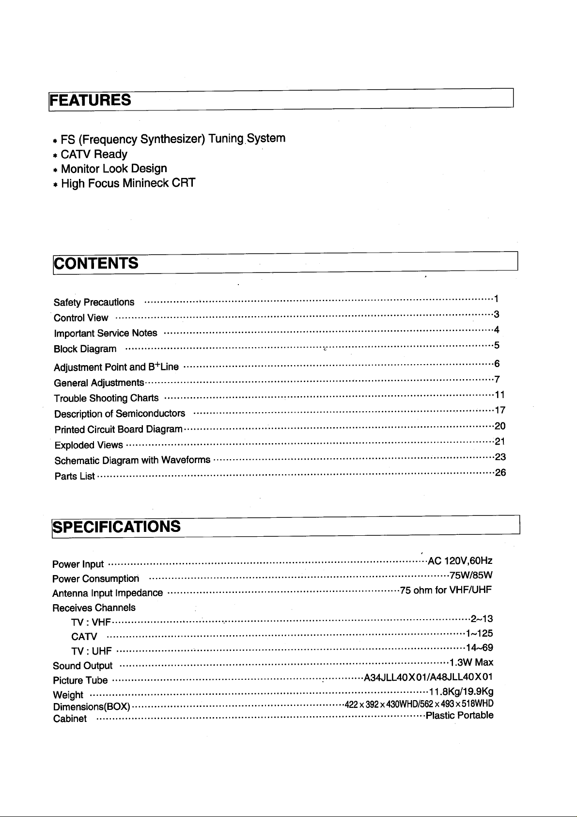
Page 1
Page 2
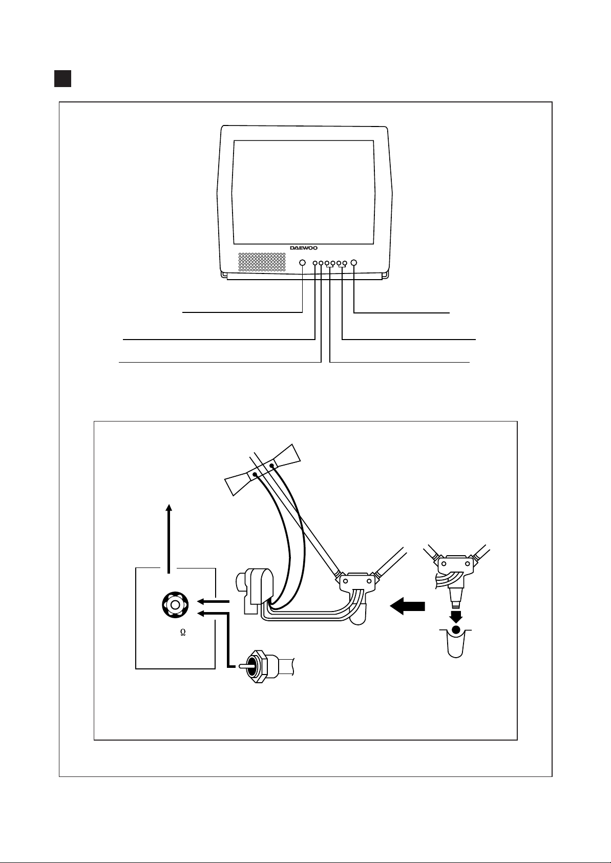
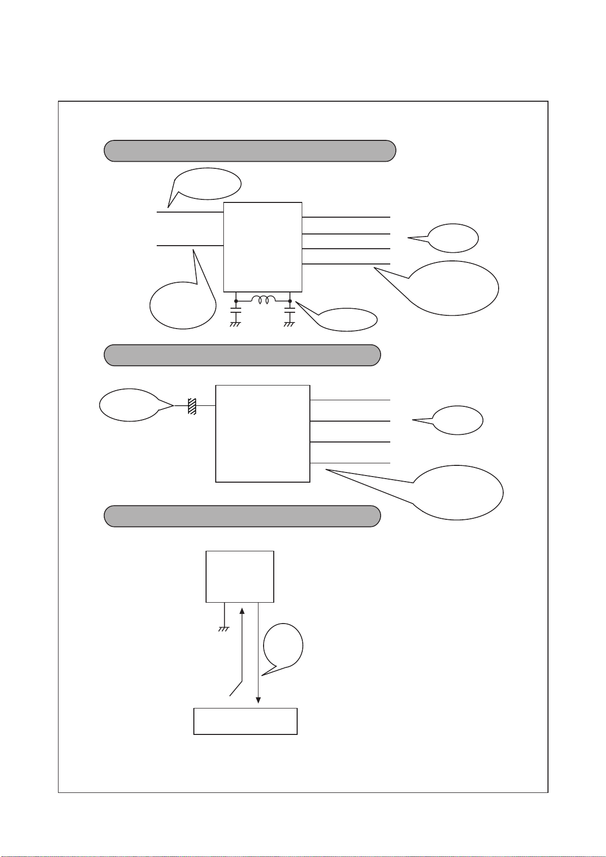
CONTROL VIEW
REMOCON SENSOR
ENTER
MENU
F-CONNECTOR
VHF
POWER ON/OFF
CH UP/DN
VOL UP/DN
300 OHM-75 OHM
COUPLING
TRANSFORMER
75
FROM 75 OHM
VHF ANTENNA WITH
CABLE OR CABLE
TV SYSTEM
3
Page 3
IMPORTANT SERVICE NOTES
1. X-RAY RADIATION PRECAUTION
1) Excessive high voltage can produce potentially
hazardous X-RAY RADIATION. To avoid such
hazards, the high voltage must not be above the
specified limit. The nominal value of the high voltage
of this receiver is 24.4kv(28.6kv) at zero beam current
(minimum brightness) under a 120V AC power source.
*
The high voltage must not, under any circumstances,
exceed 25kv (29kv). Each time a receiver requires
servicing, the high voltage should be checked following
the HIGH VOLTAGE CHECK procedure on page 7 of
this manual. It is recommended as a parts of the
service record. It is important to use an accurate and
reliable high voltage meter.
2) This receiver is equipped with X-RADIATION
PROTECTION circuit which prevents the receiver from
producing an excessively high voltage even if the
B+voltage increases abnormally. Each time the
receiver is serviced, X-RADIATION PROTECTION
circuit must be checked to determine that the circuit is
properly functioning, following the X-RADIATION
PROTECTION CIRCUIT CHECK procedure on page 7
of this manual.
3) The only source of X-RAY RADIATION in this TV
receiver is the picture tube. For continued X-RAY
RADIATION protection, the replacement tube must be
exactly the same type tube as specified in the parts list.
4) Some parts in this receiver have special safety-related
characteristics for X-RAY RADIATION protection. For
continued safety, parts replacement should be
undertaken only after referring to the PRODUCT
SAFETY NOTICE below.
2. SAFETY PRECAUTION
WARNING
: Service should not be attempted by anyone
unfamiliar with the necessary precautions on this receiver.
The following are the necessary precautions to be
observed before servicing.
1) Since the chassis of this receiver has hazardous
potential to ground whenever the receiver is plugged in
(floating chassis), an isolation transformer must be
used during servicing to avoid shock hazard.
2) Always discharge the picture tube anode to the CRT
conductive coating before handling the picture tube.
The picture tube is highly evacuated and if broken,
glass fragments will be violently expelled. Use
shatterproof goggles and keep picture tube away from
the body while handling.
3) When placing a chassis in the cabinet, always be
certain that all the protective devices are put back in
place, such as; non-metallic control knobs, insulating
covers, shields, isolation resistor-capacitor network,
etc.
4) Before returning the set to the customer, always
perform an AC leakage current check to the exposed
metallic parts of the cabinet, such as antennas,
terminals, screwheads, metal overlays, control shafts
etc. to be sure the set is safe to operate without
danger of electrical shock.
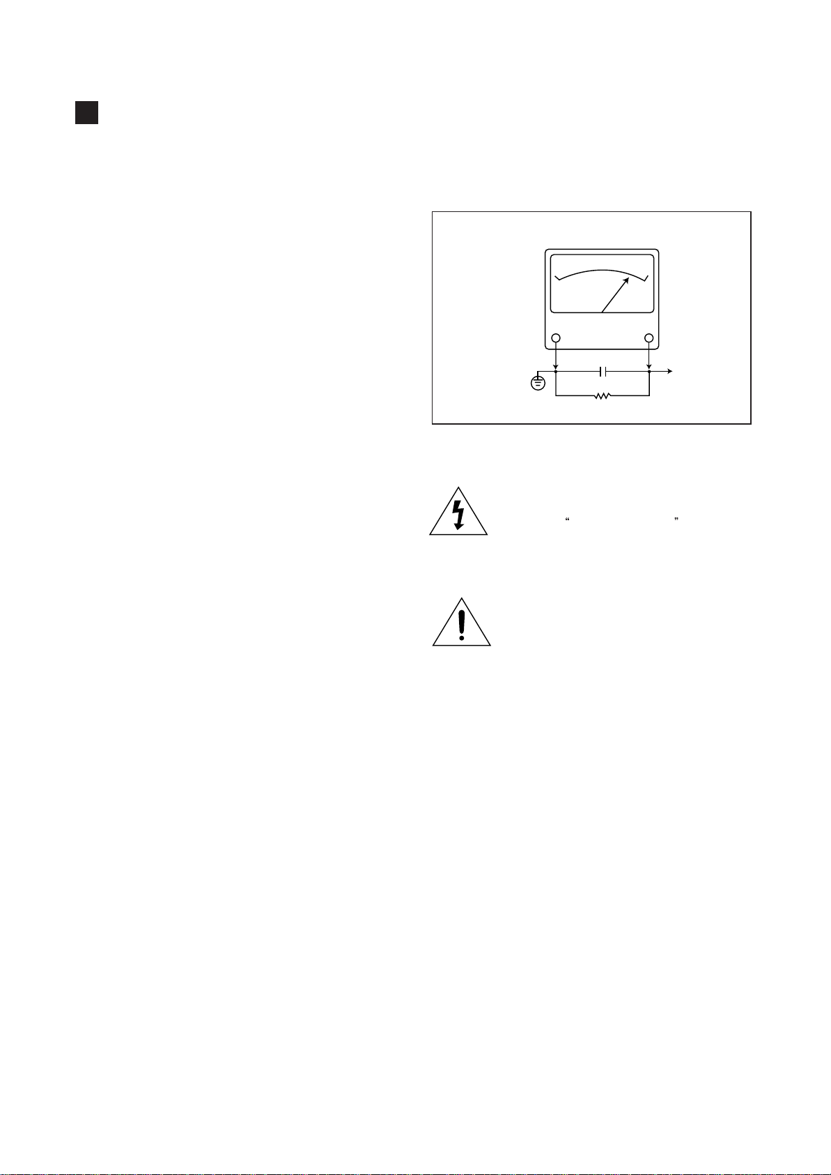
* Minimum brightness
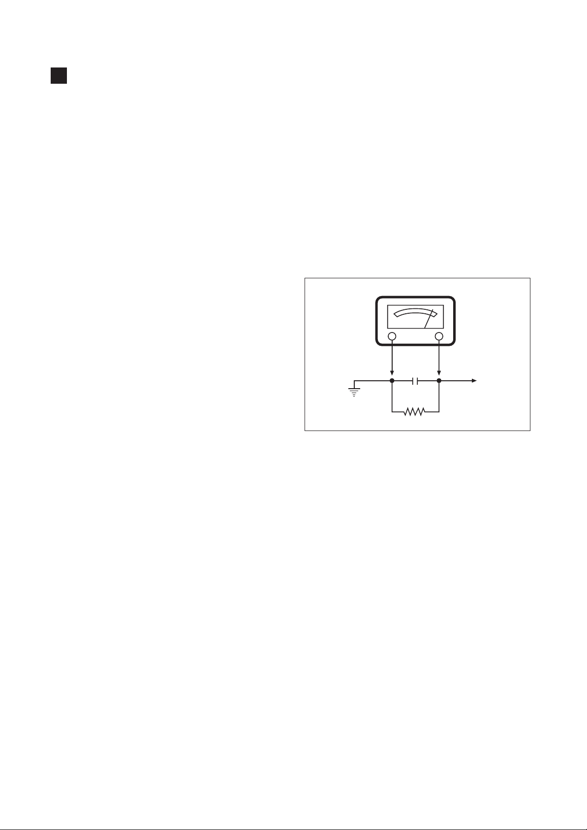
Plug the AC line cord directly into a 120V AC outlet (do
not use a line isola-tion transformer during this check).
Use an AC voltmeter having 5000 ohms per volt or
more sensitivity in the following manner.
Connect at 1500 ohm 10 watt resistor, paralleled by a
0.15µF. AC type capacitor, between a known good
earth ground (water pipe, conduit etc.) and the
exposed metallic parts, one at a time. Measure the AC
voltage across the combination of 1500 ohm resistor
and 0.15µF capacitor. Voltage measured must not
exceed 0.3 volts RMS. This corresponds to 0.2
milliamp. AC. Any value exceeding this limit constitutes
a potential shock hazard and must be corrected
immediately.
AC VOLT METER
0.15µF
Place this probe
on each exposed
metalic part.
Good earth ground
such as a water
pipe, conduit, etc.
1500 ohm
10watt
3. PRODUCT SAFETY NOTICE
Many electrical and mechanical parts in this chassis have
special safety-related characteristics. These
characteristics are often passed unnoticed by a visual
inspection and the protection afforded by them cannot
necessarily be obtained by using replacement
components rated for higher voltage, wattage, etc.
Replacement parts which have these special safety
characteristics are identified in this manual and its
supplements; electrical components having such features
are identified by shading on the schematic diagram and
the parts list.
Before replacing any of these components, read the parts
list in this manual carefully. The use of substitute
replacement parts which do not have the same safety
characteristics as specified in the parts list may create Xray radiation or other hazards.
4. SERVICE NOTES
1) When replacing parts or circuit boards, clamp or bend
the lead wires to terminals before soldering.
2) When replacing a high wattage resistor (metal oxide
film resistor) in the circuit board, keep the resistor min
1/2 inch away from circuit board.
3) Keep wires away from high voltage or high
temperature components.
4
Page 4
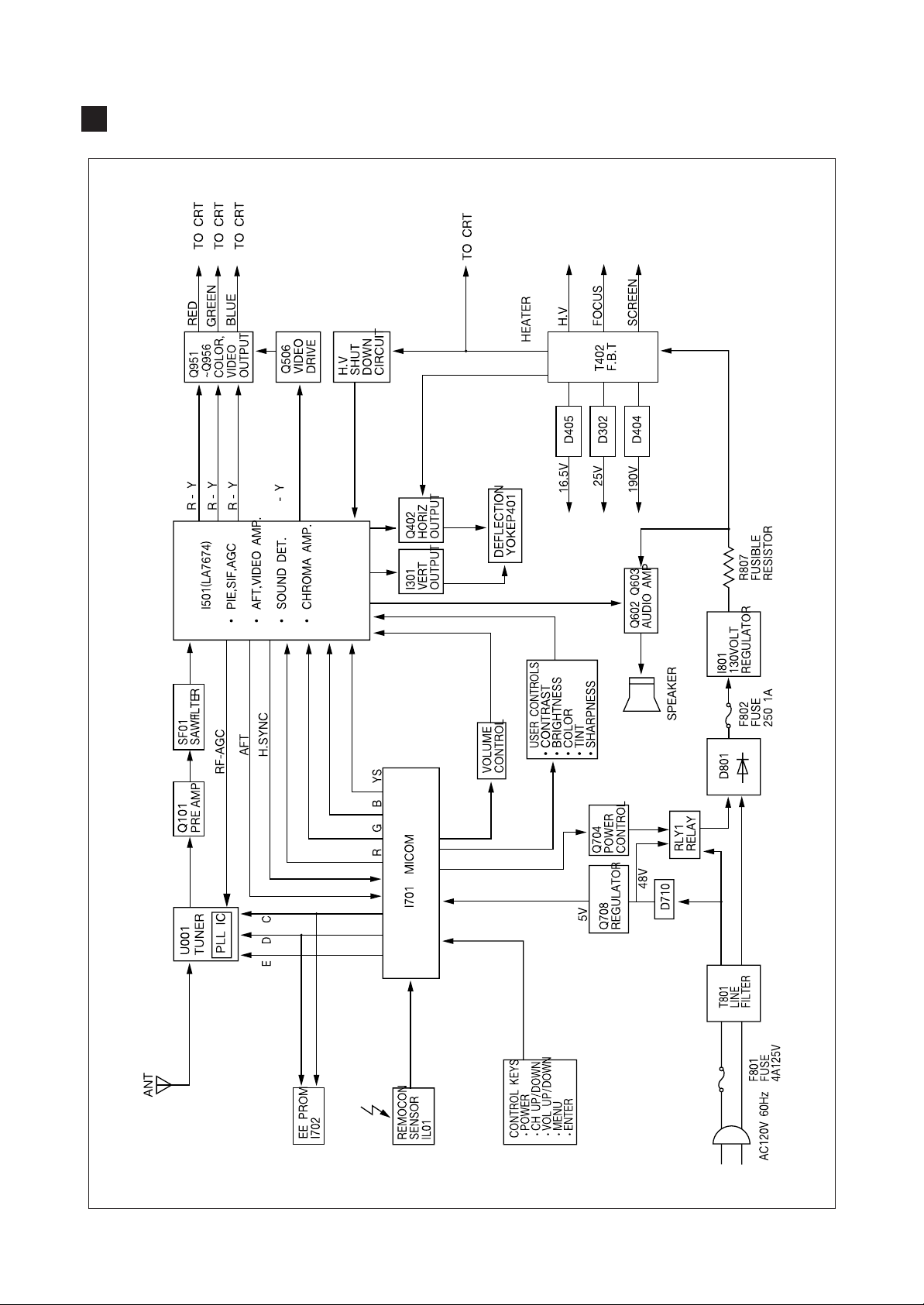
BLOCK DIAGRAM
- 5 -
Page 5

GENERAL ADJUSTMENTS
1. GENERAL
In the majority of cases, all color televisions will need only
slight touch-up adjustment upon installation. Check the
basic characteristics such as height, focus and subbright. Observe the picture for good black and white
details without objectionable color shading. If color
shading is evident, demagentize the receiver. If color
shading still persists, perform purity and convergence
adjustments. This should be all that is necessary to
achieve Optimum receiver performance.
2. VERTICAL HEIGHT ADJUSTMENT
1) Tune in an active channel.
2) Adjust brightness and contrast controls for a good
picture.
3) Adjust vertical height control (R315) for approximately
one half inch over scan at top and bottom of picture
screen.
4) Vertical centering adjustment VR316
Horizontal centering adjustment VR556.
3. FOCUS ADJUSTMENT
1) Tune in an active channel.
2) Adjust brightness, sharpness and contrast controls for a
good picture.
3) Adjust focus control (part of T402) for sharp scanning
lines and/or sharp picture.
4. RF AGC ADJUSTMENT
1) Tune in an active channel.
2) Using the attenuator, apply the signal of 60dBm to the
antenna input terminal.
3) Turn RF AGC control (VR555) full clockwise until snow
or/and noise appears in the picture, then slowly turn
control counterclockwise until snow or/and noise
disappears.
5. HIGH VOLTAGE CHECK
High voltage is not adjustable but must be checked to
verify that the receiver is operating within safe and
efficient design limitations as specified:
1) Operate Receiver for at least 15 minutes at 120V AC
line.
2) Set brightness sharpness, contrast and color control to
minumum position (Zero beam).
3) Connect accurate high voltage meter to CRT anode.
The reading should be 24.4kv(28.6kv)
DTQ-14 ----- : 22.6kv ~ 24.6kv
(
DTQ-20 ----- : 26.1kv ~ 28.8kv
If a correct reading cannot be obtained, check circuitry for
malfunctioning components.
6. X-RADIATION PROTECTION CIRCUIT
When service has been performed on the horizontal
deflection system, high voltage system or B+ system, the
X-RADIATION protection circuit must be tested for proper
operation as follows:
)
TEST
1) Operate receiver for at least 15 minutes at 120V AC
line.
2) Adjust all customer controls for normal picture and
sound.
3) Check the voltage of D401 cathode. It's voltage
should be about 22V DC.
4) Connect the cathode of diode D302 and D401 through
a 2.7K ohm, 1/4W Resistor(R313).
5) To start operation, remove the resistor and touch the
cathode of D401 to chassis ground with a short clip
lead (Remove short clip lead as soon as the set
operates again with normal picture).
6) If the operation of horizontal osc. does not stop in step
The circuit must be repaired, before the set is returned
to the customer.
7. CRT GRAY SCALE ADJUSTMENT
1) Tune in an active channel.
2) Set the COLOR control to minimum.
3) Turn the SCREEN control (on T402 fully counterclockwise.)
4) Rotate the RED, GREEN and BLUE BIAS controls
(R971, R972, R973) counterclock wise from the
maximum, set them to the position where notches in
the knobs become parallel to the surface of P.C.
Board.
5) Set the GREEN and BLUE DRIVE controls (R975,
R974) to the mid position.
6) Turn the service switch SW20 (Service Position) on
the CRT board.
7) Rotate the SCREEN control (on T402) gradually
clockwise until the second horizontal line following the
first line appears slightly on the screen. Then turn fully
counterclockwise the two BIAS controls corresponding
to the colors of the first and the second horizontal
lines to eliminated the lines.
8) Set the SCREEN control to the position where the
third horizontal line lights slightly on the screen.
9) Adjust the two BIAS control set to the minimum in item
7) above to obtain the slightly lighted horizontal line in
the same levels of three (red, green, blue) colors. (The
line should be white if the BIAS controls are adjusted
properly.)
10) Turn the service switch SW20 again (Normal position
on the CRT board.)
11) Press PICTURE-SEL, P-UP and set the brightness
and contrast controls to the maximum.
12) Adjust the BLUE and GREEN DRIVE control to obtain
proper white-blanced picture in high light areas.
13) Using P-SEL, P-DN key, set the brightness and
contrast controls to obtain dark gray raster. Then
check the white balance in low brightness. If the white
balance is not proper, retouch the BIAS controls and
DRIVE controls to obtain a good white balance in both
low and high light areas.
7
Page 6
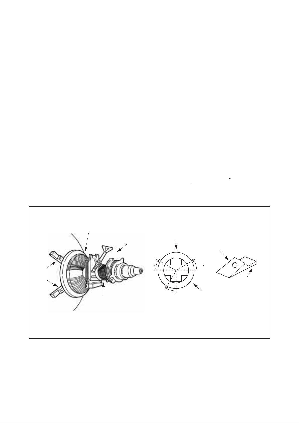
8. SUB-BRIGHTNESS ADJUSTMENT
1) Tune in a color program.
2) Set the CONTRAST control to maximum and the BRIGHTNESS control to maximum and the SHARPNESS
control to the center position.
3) Set the COLOR and TINT controls to center.
4) Set the SUB-BRIGHT control R554 to center and leave
the receiver on five minutes in this state.
5) Watching the picture carefully, adjust the SUB-BRIGHT
control in the position where the picture does not show
evidence of blooming in high brightness area and not
appear too dark in low bright area.
6) Check for BRIGHTNESS controls at both extremes.
7) If the picture does not appear dark with the
CONTRAST and BRIGHTNESS control turned to
minimum, or not appear bright with the controls turned
to maximum, adjust the SUB-BRIGHT control again for
an acceptable picture.
9 . CONVERGENCE MAGNET ASSEMBLY
POSITIONING
If Convergence magnet assembly and rubber wedges
need mechanical positioning follow figure 2.
9-1. COLOR PURITY ADJUSTMENT
NOTE
1) Demagnetize the picture tube with a degaussing coil.
2) Adjust the CONTRAST and BRIGHTNESS controls to
3) Adjust RED and BLUE Bias controls (R971 and R973)
4) Loosen the clamp screw holding the yoke, and slide
5) Remove the Rubber Wedges.
6) Rotate and spread the tabs of the purity magnet (See
7) Move the yoke slowly forward until a uniform green
8) Check the purity of the red and blue raster by adjusting
9) Obtain a white raster, referring to
10) Proceed with covergence adjustment.
: Before attempting any purity adjustments, the
receiver should be operated for at least 15
minutes.
maximum
to provide only a green raster. Adjust the GREEN BIAS
control (R972) if necessary.
the yoke backward to provide vertical green
belt(zone)in the picture screen.
figure 2) around the neck of the picture tube until the
green belt is in the center of the screen. At the same
time, center the raster vertically.
screen is obtained. Tighten the clamp screw of the
yoke temporarily.
the BIAS controls.
CRT GRAY SCALE
ADJUSTMENT
.
RUBBER
WEDGES
PICTURE TUBE
DEFLECTION
YOKE
GLASS CLOTH
TAPE
CONVERGENCE
MAGNET ASS'Y
TEMPORARY
MOUNTING
{
30 30
30
Fig. 2 Rubber Wedges Location
RUBBER
WEDGES
ADHESIVE
DEF.
YOKE
8
Page 7
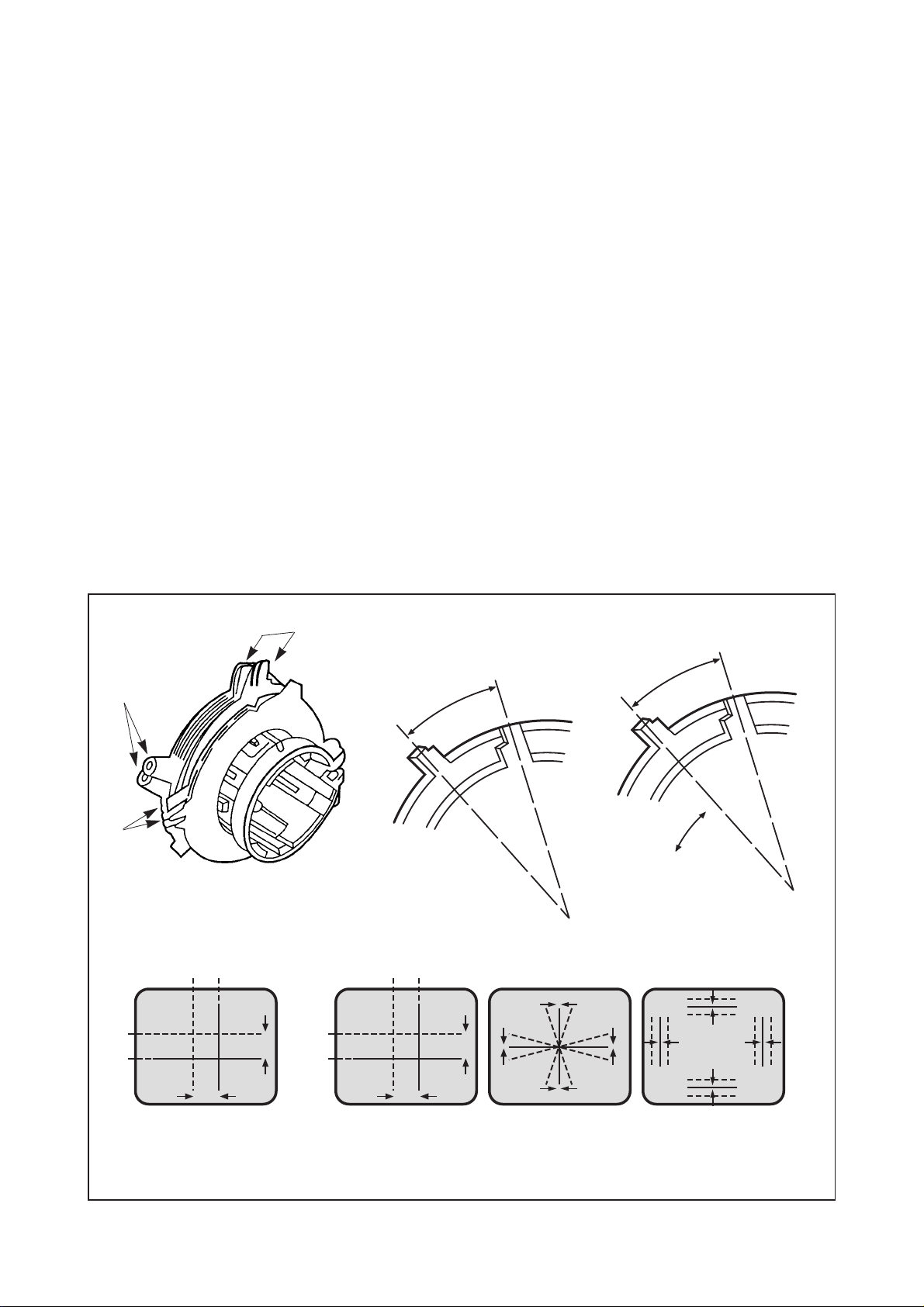
9-2. CONVERGENCE ADJUSTMENTS
BLUE
BLUE
4-Pole Magnets Movement 6-Pole Magnets Movement Incline the Yoke up(or down) Incline the Yoke right(or left)
Center Convergence by Convergence Magnets Circumference Convergence by DEF. Yoke
RED
RED
RED/BLUE
RED/BLUE
GRN
GRN
B G R
BGR
R
G
B
B
G
R
R G B
R
G
B
B
G
R
BGR
NOTE
: Before attempting any purity adjustments, the
receiver should be operated for at least 15
minutes.
A. CENTER CONVERGENCE ADJUSTMENT
1) Receive crosshatch pattern with a crosshatch signal
generator.
2) Adjust the BRIGHTNESS and CONTRAST Controls for
a good picture.
3) Adjust two tabs of the 4-Pole Magnets to change the
angle between them (See Fig. 3) and superimpose red
and blue vertical lines in the center area of the picture
screen. (See Fig. 4)
4) Turn both tabs at the same time keeping their angles
constant to superimpose red and blue horizontal lines
at the center of the screen. (See Fig. 4)
5) Adjust two tabs of 6-Pole Magnets to superimpose
red/blue line with green on top of each other. Adjusting
the angle affects the vertical lines and rotating both
magnets affects the horizontal lines.
6) Repeat adjustments 3), 4), 5) keeping in mind red,
green and blue movement, because 4-Pole Magnets
and 6-Pole Magnets interact and make dot movement
complex.
B. CIRCUMFERENCE CONVERGENCE ADJUSTMENT
: This adjustment requires Rubber Wedge Kit.
NOTE
1) Loosen the clamping screw on deflection yoke to allow
the yoke to tilt.
2) Place a wedge as shown in figure 2 temporarily. (Do
not remove cover paper on adhesive part of the
wedge.)
3) Tilt front of the deflection yoke up or down to obtain
better convergence in circumference. (See Fig. 4) Push
the mounting wedge into the space between picture
and the yoke to hold the yoke temporarily.
4) Place other wedge into bottom space and remove the
cover paper to stick.
5) Tilt front of the yoke right or left to obtain better
convergence in cicumference. (See Fig. 4)
6) Hold the yoke position and put another wedge in either
upper space. Remove cover paper and stick the wedge
on picture tube to hold the yoke.
7) Detach the temporarily mounted wedge and put it in
another upper space. Stick it on picture tube to fix the
yoke.
8) After placing three wedges, re-check overall
convergence. Tighten the screw firmly to hold the yoke
tightly in place.
9) Stick 3 adhesive tapes on wedges as shown in figur3,2.
4-POLE
MAGNETS
PURITY
MAGNETS
6-POLE
MAGNETS
CONVERGENCE MAGNET ASSEMBLY
ADJUST THE
ANGLE
(VERTICAL
LINES)
Fig. 3
CONSTANT
ROTATE TWO TABS AT
THE SAME TIME
(HORIZONTAL LINES)
ADJUSTMENT OF MAGNET
Fig. 4 Dot Movement Pattern
9
Page 8
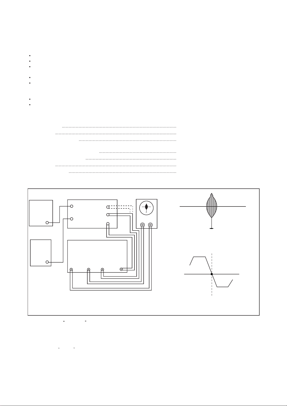
10. PICTURE IF/AFT ADJUSTMENTS
NOTE
: THIS RECEIVER IS TRANSISTORIZED AND SPECIAL CARE MUST BE TAKEN WHEN SERVICING. READ
THE FOLLOWING (NOTES BEFORE ATTEMPTING ALIGNMENT)
Alignment requires an exacting procedure and should be undertaken only when necessary.
Isolation transformer must be used to prevent shock hazard.
The test equipment specified or its equivalent is required to perform the alignment properly. Use of equipment which
does not meet these requirements may result in improper alignment.
Accurate equipment is essential to obtain proper alignment of this receiver.
Use of excessive signal from a sweep generator can cause overloading of receiver circuit Overloading should be
avoided to obtain a true response curve. Insertion of markers from the marker generator should not cause distortion of
the response curve.
The AC Power line voltage should be kept 120 volts while alignment is being performed.
Do not attempt to disconnect any components while the receiver is in operation.
Make sure the power cord is disconnected before replacing any parts in the receiver.
TEST EQUIPMENT
Digital voltmeter National Model VP-2600A or equivalent
Oscilloscope
Direct/Low-capacity probe
Tektronix Model 2215A or equivalent.
Tektronix Model P6120 or equivalent
(Accessory of oscilloscope)
Color-Bar/Dot/Crosshatch generator
PIF sweep marker generator
Power supply
Isolation transformer
Tektronix Model 146 or equivalent.
Nihon Tsushinki Model 4723 or equivalent
Academy Model 150A or equivalent
Voltage adjustable type having capacity of
at least 150 watts
BLOCK DIAGRAM
B+
BIAS
POWER
SUPPLY
A
(16.5V)
AGC
BIAS
POWER
SUPPLY
B
(4-5V)
1) Disconnect the
MAIN BOARD
TP3
TP5
PIF SWEEP/MARKER GEN.
VH
Fig. 5 Picture IF Sweep Alignment
TP6
TP1
TP4
DET IN
OUT
TUNER IF output from TP1 and connect equipment as shown above.
OSCILLOSCOPE
Y
X
45.75MHz
Fig. 6 PIF Response
P
45.75MHz
Fig. 7 AFT Response Curve
2) Set the sweep/marker generator for 30 Vrms.
3) Observe 1 Vp-p on scope by adjusting power supply B (4~5V).
4) Adjust PIF coil L505 for according beat signal with 45.75 MHz marker on scope (See Fig. 6).
5) Connect the
DET IN to TP6.
6) Adjust AFT coil L504 for center display at 45.75 MHz on scope (See Fig. 7).
7) After completing the above steps, disconnect equipment and adjust the AGC delay circuit as explained in the General
Adjustments section of this manual.
10
Page 9
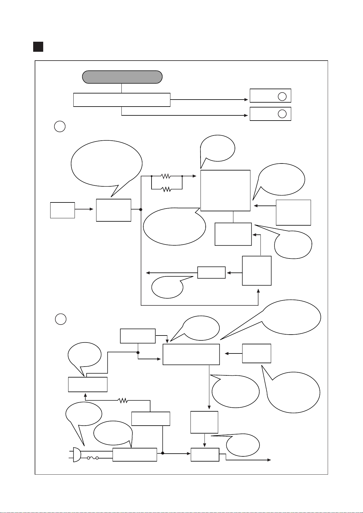
TROUBLE SHOOTING CHARTS
NO POWER
A
RLY1
RELAY
DOES RLY1 (RELAY) OPERATE?
CHECK
IN/OUT VOLTAGES
OF I801(130VOLT REG)
IN: 150V
OUT: 130V
DC
DC
CHECK
I801
STR30130
130V
R413 18K
2WATT
R414 20K
2WATT
DC
IF #26 NORMAL
& NO OUTPUT AT
#23 THEN
CHANGE I501
16.5V
CHECK
16.5V LINE
YES
NO
CHECK
#30
(7.5V
DC
)
30
I501
26 23
Q402
H. OUTPUT
D405
24
GO TO
GO TO
T402
F.B.T
5
4
4
A
B
DOES
SHUT DOWN
CIRCUIT
OPERATE?
H.V
SHUT DOWN
OCCURS AT
22VDC
CHECK
Q402
COLLECTOR
B
5V
SHOULD
BE
4.3V-5.2V
Q708
REGULATOR
CHECK
F801
125V 4A
CHECK
LEAD
SOLDERING
Q701
RESET
R759
D710
L801
LINE FILTER
CHECK
ALL THE POINTS
THEN CHANGE
NORMAL: 5V
RESET: 0V
1
I701
2
9
23
OPEN LOAD
THEN CHECK
#23 ON STATE
4 ~5V
Q704
POWER
CONTROL
RLY1
RELAY
PWR
CONTROL
KEY
CHECK
Q704 &
RELAY
I701
KEY OPERATE?
CHECK DIODE
D701 & SWITCH
KEY BOARD
11
Page 10
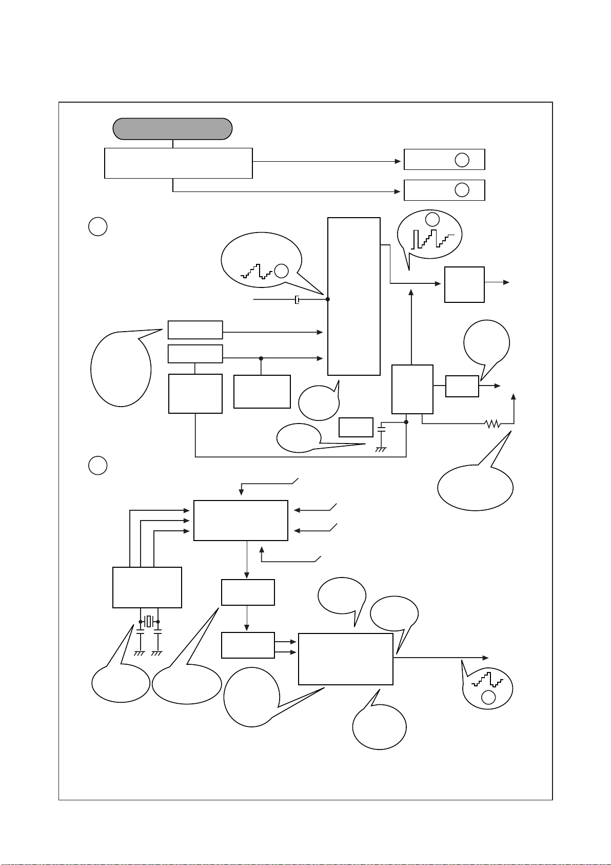
21
42
39
3
7
7
4
10
9
9
10
8
8
16
15
14
14112
10
44
31
11 14
C
D
H
H
GO TO
OK
CHECK THE WAVE FORM OF
I501 #44
NG
NO PICTURE
GO TO
I501
LA 7674
COMPOSITE
VIDEO INPUT
C
D
C217
Y-OUT
DRIVE
H. BLANKING
CHECK
190V
LINE
D404
Q506
VIDEO
CONTRAST
BRIGHT
CHECK
C410
R554
SUB-BRIGHT
CHECK
9V LINES
#11,14
C410
0.1 (M)
AGC
PIN 4
Q501
ABL
CHECK
CONTROL
(MAX)
VOLTAGES
#39:7.5V
#31:6.2V
12V
5V
V
T
(33V)
U001 TUNER
IF
ENA
DATA
CLK
CHECK
CRYSTAL
X701
CHECK THE
VOLTAGE
AT Q101
CHECK
IF AGC
VTG.
5V
DC
SF01
SAW FILTER
Q101
PRE-AMP
I501
LA7674
ADJUST
RF-AGC
R555
DETECTOR
OUTPUT
CHECK
9V LINE
#11, 14
TO Q504
CHECK
HEATER
VTG 6.3Vrms
R402
T402
FBT
H
I701
4241
12
Page 11
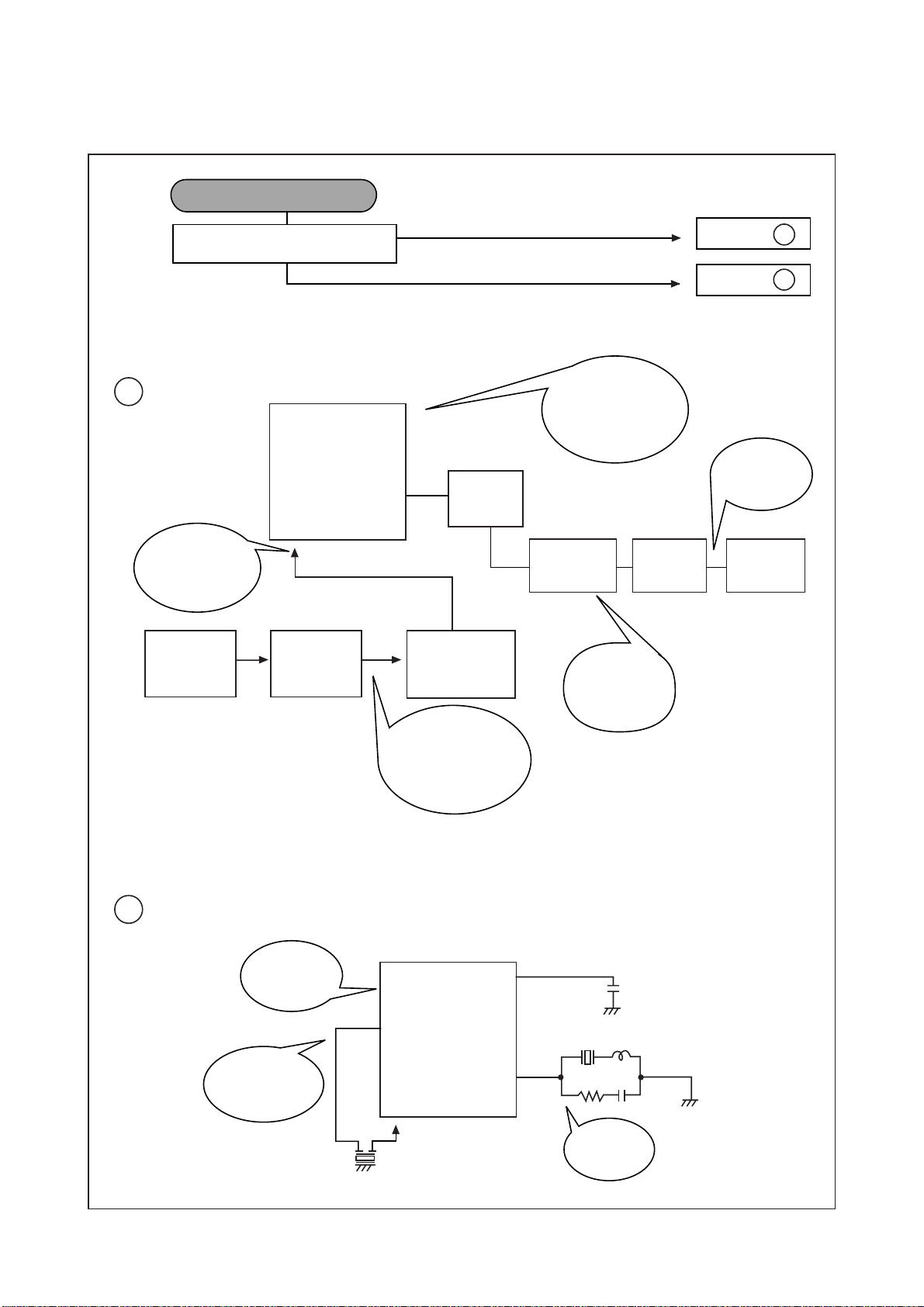
4
6
30
11
1
14
44
48
4
48
E
F
GO TO
YES
CHECK FOR SIGNAL
AT I501 #6
NO
NO SOUND
GO TO
E
F
I501
LA7674
VOL-UP
DOWN
CONTROL
KEY
SOUND VOLUME
MAX: ~7V
DC
MIN: ~1V
DC
CHECK
CONNECTOR
P601
I701
CHECK
9V
DC
LINE#11,14
LOW PASS
FILTER
Q602,Q603
AUDIO
OUT
T601
TSP1036
SP01
SPEAKER
Q601
AUDIO
AMP
DISCONNECT LOAD
CHECK FOR SND,
PWM SIGNAL, IF
MISSING REPLACE
I701
SOUND TAKEOFF
NO OUTPUT:
CHANGE I501
DE EMPHASIS
CHECK
FM DET.
CIRCUIT
CHECK
R601 &
123V LINE
X601
I501
LA7674
SOUND
IF INPUT
Z601
IF #4 IS OK
& NO OUTPUT
THEN
CHANGE I501
13
Page 12
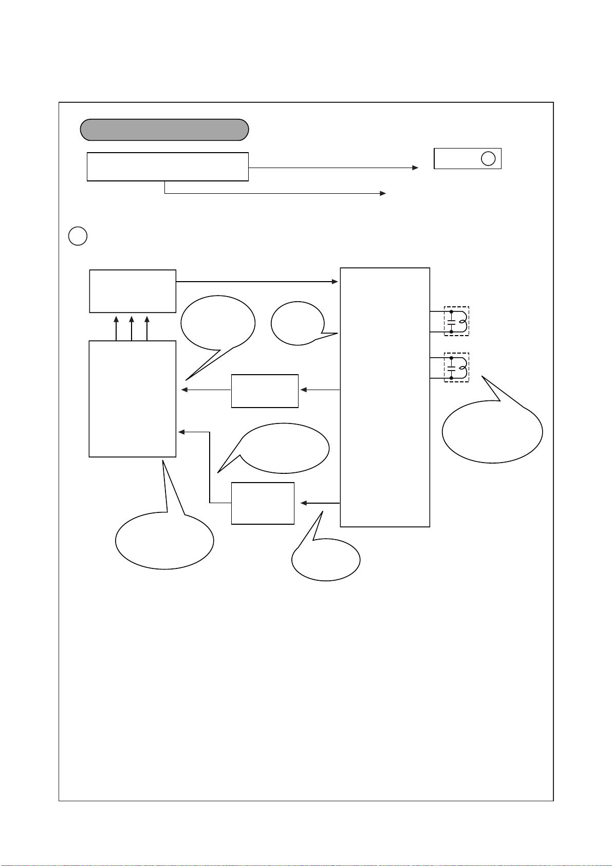
8, 9
10
47
12 15
16
39
38
24
8
27
51
50
46
45
G
GO TO
GOOD
CHECK INPUT SIGNAL
CONDITIONS
BAD
CH DON'T STOP
G
LOSS OF SIGNAL OR
WEAK SIGNAL
IF OUTPUT
CHECK
AFT WINDOW
VTG.
1.6V ~ 3.4V
ADJUST
RF AGC
R555
U001
TUNER
I701
H: NO SIGNAL
L: SIGNAL
S.D SIGNAL
DETECTION
ADJUST
PIF & AFT
REFER TO GENERAL
ADJUSTMENTS
I501
LA7674
AFT
PIF
Q507 AFT
DETECTOR
IF
S.D & AFC
ARE OK THEN
CHANGE IC701
Q702,Q709
SWITCHING
CIRCUIT
14
Page 13
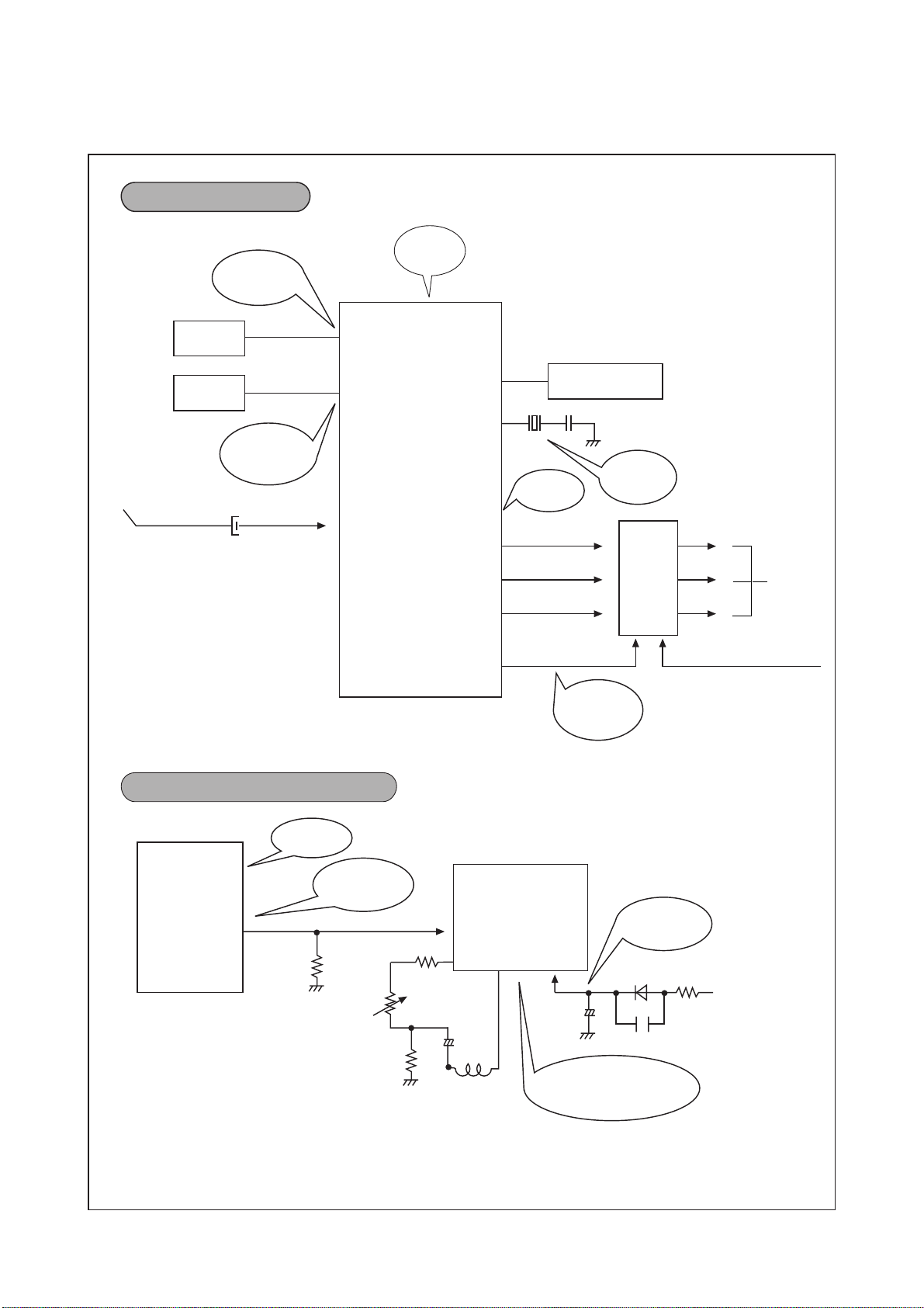
TINT
COLOR
X501
C517
COMPOSITE
VIDEO
APC FILTER
NO COLOR
NO VERTICAL DEFLECTION
MAX.
6V
CHECK
9V
DC
MAX.
4V
R-Y
LUMINANCE (-Y) 190V LINE
TO CRT
G-Y
B-Y
CHECK
9V
DC
CHECK
CRYSTAL
CHECK
CONNECTOR
P101
I501
LA7674
I501
LA7674
Q951
~
Q956
R
G
B
41
36
42
12
13
14
18
19
20
21
14
12
2
48
28
11
CHECK 9V
DC
CHECK
VERT.OUT
I301
LA7837
CHECK THE WAVEFORM
I301 #12 NO OUTPUT:
CHANGE I301
R304
D302 R305
C308
R315
C309
C306
V.D.Y.
R301
R311
+
V,HEIGHT
CHECK 25V
DC
CRT
DRIVE
15
Page 14
REMOTE CONTROL DOES NOT OPERATE
CAPTION DISPLSY DOES NOT OPERATE
IL01
REMOCON
SENSOR
ON SCREEN DISPLAY DOES NOT OPERATE
I701
CHECK
FOR 60Hz
OSC CHECK
R
G
YS
CHECK
FOR 15, 734Hz
Vsync
Hsync
GND 5V OUT
CHECK
WAVEFORM
I701
5V
19
25
24
42
18
B
17
22
41
COMPOSITE
VIDEO 2Vpp
R, G, B, YS
CHECK
IF OSD DOES NOT
OPERATE, CHANGE
I701
R, G, B, YS
CHECK
IF CAPTION
DOES NOT
OPERATE.
CHANGE I701
I701
R
G
B
YS
19
13
18
17
22
3
16
Page 15
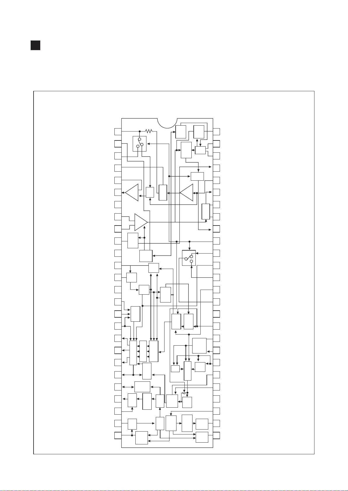
DESCRIPTION OF SEMICONDUCTORS
LA7674 (VIF/SIF/VIDEO/CHROMA/DEFLECTION)
1. Case Outline : SDIP 52P
2. Pin Connections/Block Diagram
I501 LA7674
IF/VIDEO/CHROMA/DEF
FM DET
IF AGC
EX AIN
FM DET
NFB
A
OUT
GND
IF
IF IN
RF AGC
VCC
APC
VXO
VCC
R
1
LOCK
DET
2
3
4
5
ATT
FMDET
AF-
6
AMP
7
8
IN
VIF
AMP
9
RF-
10
AGC
11
12
13
14
15
IN
VCO
TINT
IF-
AGC
APC
ACC
KILL-
ER
VIDEO
DET
LIM
AMP
APC
DET
VCO
VIDEO
AMP
AFT
52
51
50
49
48
47
46
45
44
43
42
41
40
39
38
IFAPC
VCO
VCO
RF AGC
SIF
IN
AFT OUT
AFT
AFT
V
DET
AV S.W
V
IN
TINT
EX. V
IN
CONT
VIDEO
GIN
BIN
R-Y
G-Y
B-Y
-Y
FBP
HOUT
HOLDDOWN
HOSC
HAFC
OSD
16
17
18
19
20
OSD-SWITCH
CARRIER-F
COLOR
DEMO
FBT-DET
-Y OUT
2NA
BPA
SOFT
IST
BPA
CONTRAST
BLACK
EXPAND
SHARP
21
DRIVER
HOR
FBT-
DET
SHIFTRE
PHASE
AFC
CLAMP
BRIGHT
2
D.L
22
IN
23
24
25
26
OSC
HOR
AFC
HOR
C/D
1
SYNC/
SEP
VER
SYNC-
SEP
VER
C/D
HOR
COIN
37
36
35
34
33
32
31
30
29
28
27
GND
COLOR
B
DET
YIN
SHARP
CLAMP
BRIGHT
V
CCH
SSEP
VOUT
HDET
17
Page 16
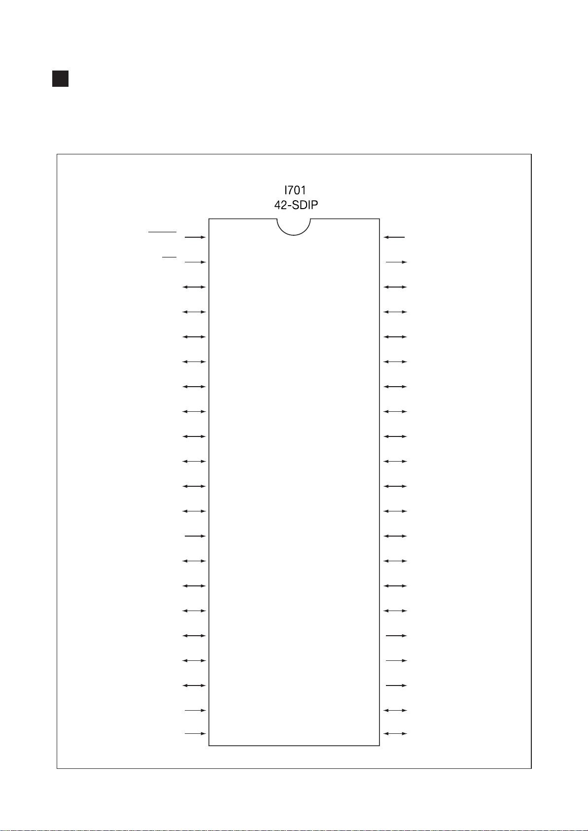
LSC420142B/43B
1) Case Outline : DIP-42S plastic package
2) Function: C-MOS 4 bit microcomputer, PWM control, CHANNEL SEARCH/MEMORY, ON/OFF, timer, sleep time, on
screen display, TV/CATV (STD,HRC,IRC)
3) PIN connections
(TUNING CONTROL)
RESET
IRQ
PC4/PAMIN
PC5
PA7
PA6
PA5
PA4
PA3
PA2
PA1
PA0
1
42
41
40
39
38
37
36
35
34
33
32
31
OSC1
OSC22
PC33
PC2/ADCIN4
PC15
PB7/DA76
PB6/DA67
PB5/DA58
PB4/DA49
PB3/DA310
PB2/DA211
PB1/DA112
VIDEO
PD0
PD1/SDIO
PD2/SCK
PD3/B
PD4/G
PD5/R
V
DD
V
SS
18
30
29
28
27
26
25
24
23
22
PB0/DA013
PC014
PC615
VCO16
PLLGND17
VSYN18
HSYN19
PD720
PD6/FBKG21
Page 17
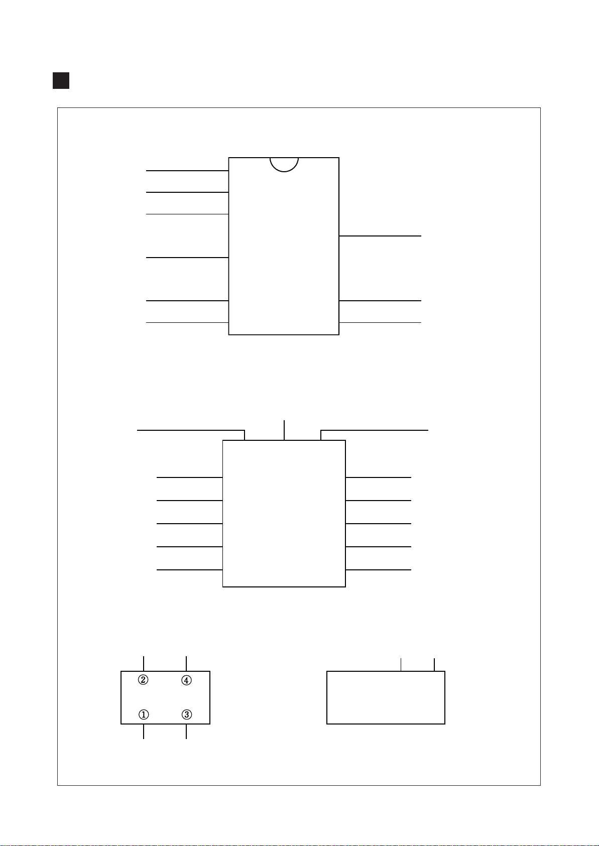
DESCRIPTION OF SEMICONDUCTORS AND TUNER
TUNER(U001)
ENA
DATA
CLK
+5V
BP
BT
VERT TRIGGER
INPUT
16
15
14
13
12
11
10
9
1
2
3
4
5
6
7
8
VERTICAL OUTPUT(I301)
PUMP-UP OUTPUT
2 9 13
AGC
+12V
IF
POWER SUPPLY
FOR V-OUT
+9V
50/60Hz
ONE SHOT
GND
RAMP GEN.
130V REGULATOR(I801)
BASE
GROUND
OUTPUT
INPUT
1
5
3
11
6
1
5
3
11
6
+25V
OSC BLOCKING
V-OUT
AC/DC FEED BACK
VERT.HEIGHT
EEPROM(I702)
CLOCK
8 7 6 5
1 2 3 4
DATA
19
Page 18
SAFETY PRECAUTIONS
Product safety servicing guidelines for color
television receivers
CAUTION :
way. Unauthorized modifications will not only void the
warranty, but may lead to your being liable for any
resulting property damage or user injury.
Service work should be performed only after you are
thoroughly familiar with all of the following safety checks
and servicing guidelines. To do otherwise, increases the
risk of potential hazards and injury to the user.
SAFETY CHECKS
After the original service problem has been corrected, a
check should be made of the following:
SUBJECT : FIRE & SHOCK HAZARD
1. Be sure that all components are positioned in such a
way as to avoid possibility of adjacent component
shorts. This is especially important on those chassis
which are transported to and from the repair shop.
2. Never release a repair unless all protective devices
such as insulators, barriers, covers, shields, strain
reliefs, and other hardware have been reinstalled per
original design.
3. Soldering must be inspected to discover possible cold
solder joints, frayed leads, damaged insulation
(including A.C. cord), solder splashes or sharp solder
points. Be certain to remove all loose foreign particals.
4. Check for physical evidence of damage or deterioration
to parts and components, and replace if necessary
follow original layout, lead length and dress.
5. No leads or components should touch a receiving tube
or a resistor rated at 1 watt or more. Lead tension
around protruding metal surfaces must be avoided.
6. All critical components such as fuses, flameproof
resistors, capacitors, etc. must be replaced with exact
factory types. Do not use replacement components
other than those specified or make unrecommended
circuit modifications.
7. After re-assembly of the set always perform an A.C.
leakage test on all exposed metallic parts of the
cabinet, (the channel selector knob, antenna terminals,
handle and screws) to be sure the set is safe to operate
without danger of electrical shock. Do not use a line
isolation transformer during this test. Use an A.C.
voltmeter, having 5000 ohms per volt or more
sensitivity, in the following manner : connect a 1500
ohm 10 watt resistor, paralleled by a 0.15µF. 150V A.C.
type capacitor between a known good earth ground
(water pipe, conduit, etc.) and the exposed metalic
parts, one at a time. Measure the A.C. voltage across
the combination of 1500 ohm resistor and 0.15µF
capacitor. Reverse the A.C. plug and repeat A.C.
voltage measurements for each exposed metallic part.
Voltage measured must not exceed 0.75 volts R.M.S.
Do not attempt to modify this product in any
This corresponds to 0.5 milliamp A.C. Any value
exceeding this limit constitutes a potential shock hazard
and must be corrected immediately.
A.C. VOLTMETER
Good earth ground,
such as the water
pipe, conduit, etc.
GRAPHIC SYMBOLS :
The lightning flash with arrowhead symbol,
within an equilateral triangle, is intended to
alert the service personnel to the presence of
uninsulated
of sufficienty magnitude to constitute a risk of
electric shock.
The exclamation point within an equilateral
triangle is intended to alert the service
personnel to the presence of important safety
information in service literature.
SUBJECT : X-RADIATION
1. Be sure procedures and instructions to all service
personnel cover the subject of X-radiation. The only
potential source of X-rays in current T.V. receivers is
the picture tube. However, this tube does not emit Xrays when the high voltage is at the factory specified
level. The proper value is given in the applicable
schematic. Operation at higher voltages may cause a
failure of the picture tube or high voltage supply and,
under certain circumstances, may produce radiation in
excess of desirable levels.
2. Only factory specified C.R.T. anode connectors must
be used. Degaussing shields also serve as X-ray shield
in color sets. Always re-install them.
3. It is essential that the serviceman has available an
accurate and reliable high voltage meter. The
calibration of the meter should be checked perio dically against a reference standard. Such as the one
available at your distributor.
4. When the high voltage circuitry is operating properly
there is no possibility of an X-radiation problem. Every
time a color chassis is serviced, the brightness should
0.15µF
1500 OHM
10WATT
dangerous voltage that may be
Place this probe
on each exposed
metal part.
1
Page 19

be run up and down while monitoring the high voltage with
a meter to be certain that the high voltage does not
exceed the specified value and that it is regulating
correctly. We suggest that you and your service
orgainzation review test procedures so that voltage
regulation is always checked as a standard servicing
procedure. And that the high voltage reading be recorded
on each customer'sinvoice.
5. When troubleshooting and making test measurements
in a receiver with a problem of excessive high voltage,
avoid being unnecessarily close to the picture tube and
the high voltage compartment.
Do not operate the chassis longer than is necessary to
locate the cause of excessive voltage.
6. Refer to HV, B+ and Shutdown adjustment procedures
described in the appropriate schematic and
diagrams(where used).
SUBJECT : IMPLOSION
1. All direct viewed picture tubes are equipped with an
integral implosion protection system, but care should be
taken to avoid damage during installation. Avoid
scratching the tube. If scratched, replace it.
2. Use only recommended factory replacement tubes.
SUBJECT : TIPS ON PROPER
INSTALLATION
1. Never install any receiver in closed-in recess,
cubbyhole or closely fitting shelf space over, or close to
heat duct, or in the path of heated air flow.
2. Avoid conditions of high humidity such as : Outdoor
patio installations where dew is a factor. Near steam
radiators where steam leakage is a factor, etc.
3. Avoid placement where draperies may obstruct rear
venting. The customer should also avoid the use of
decorative scarves or other coverings which might
obstruct ventilation.
4. Wall and shelf mounted installations using a
commercial mounting kit, must follow the factory
approved mounting instructions. A receiver mounted to
a shelf or platform must retain its original feet(or the
equivalent thickness in spacers) to provide adequate
are flow across the bottom, blots or screws used for
fasteners must not touch any parts or wiring. Perform
leakage test on customized installations.
5. Caution customers against the mounting of a receiver
on sloping shelf or a tilted position, unless the receiver
is properly secured.
6. A receiver on a roll-about cart should be stable on its
mounting to the cart. Caution the customer on the
hazards of trying to roll a cart with small casters across
thresholds or deep pile carpets.
7. Caution customers against the use of a cart or stand
which has not been listed by underwriters laboratories,
inc. For use with their specific model of television
receiver or generically approved for use with T.V.'s of
the same or larger screen size.
2
Page 20
WARNING:BEFORE SERVICING THIS CHASSIS, READ THE "X-RAY RADIATOIN,PRECAUTION "SAFETY
✔ Caution:In this Service Manual, some parts can be changed for improving, their performance without notice in the parts list. So, if you need the
latest parts information, please refer to PPL(Parts Price List) in Service information Center(http://svc.dwe.co.kr)
PRECAUTION" AND "PROUCT SAFETY NOTICE" ON P AGE1 OF THIS MANUAL
REPLACEMENT PARTS LIST
LOC. PART-CODE PART-NAME PART-DESC
C101 CCZF1E103Z C CERA 25V F 0.01MF Z (AXIAL)
C102 CCZF1E103Z C CERA 25V F 0.01MF Z (AXIAL)
C103 CCZF1E103Z C CERA 25V F 0.01MF Z (AXIAL)
C104 CEXF1C471V C ELECTRO 16V RSS 470MF (10X12.5)TP
C105 CEXF1H109V C ELECTRO 50V RSS 1MF (5X11) TP
C106 CEXF1H229V C ELECTRO 50V RSS 2.2MF (5X11) TP
C301 CMXM2A104J C MYLAR 100V 0.1MF J TP
C302 CMXM2A103J C MYLAR 100V 0.01MF J (TP)
C303 CEXD1H229Q C ELECTRO 50V RT 2.2MF (6.3X11) TP
C304 CEXF1H470V C ELECTRO 50V RSS 47MF (6.3X11) TP
C305 CXSL2H100D C CERA 500V SL 10PF D (TAPPING)
C306 CEXF1V471V C ELECTRO 35V RSS 470MF (10X20) TP
C307 CEXD1H229Q C ELECTRO 50V RT 2.2MF (6.3X11) TP
C308 CCXB2H471K C CERA 500V B 470PF K (TAPPING)
C309 CEXF1E102V C ELECTRO 25V RSS 1000MF (13X20) TP
C310 CEXF1C470V C ELECTRO 16V RSS 47MF (5X11) TP
C401 CEXF2C109V C ELECTRO 160V RSS 1MF (6.3X11) TP
C402 CCXB2H102K C CERA 500V B 1000PF K (TAPPING)
C403 CCXB2H471K C CERA 500V B 470PF K (TAPPING)
C404 CMYH3C622J C MYLAR (20") 1.6KV 6200PF J (BUP)
C404 CMYH3C602J C MYLAR (14") 1.6KV 6000PF J (BUP)
C405 CEXF1H479V C ELECTRO 50V RSS 4.7MF (5X11) TP
C406 CEXF1E102V C ELECTRO 25V RSS 1000MF (13X20) TP
C407 CEXF1H479V C ELECTRO 50V RSS 4.7MF (5X11) TP
C408 CEXF1H109V C ELECTRO 50V RSS 1MF (5X11) TP
C409 CEXF1H220V C ELECTRO 50V RSS 22MF (5X11) TP
C410 CMXM2A104J C MYLAR 100V 0.1MF J TP
C411 CCXB2H152K C CERA 500V B 1500PF K (TAPPING)
C412 CCXB2H152K C CERA 500V B 1500PF K (TAPPING)
C413 CMYE2D514J C MYLAR (20") 200V 0.51MF J (PL)
C413 CMYE2D474J C MYLAR (14") 200V 0.47MF J (PL)
C414 CEXF2C109V C ELECTRO 160V RSS 1MF (6.3X11) TP
C415 CEXF2E100V C ELECTRO 250V RSS 10MF (10X20) TP
C416 CCXB2H102K C CERA 500V B 1000PF K (TAPPING)
C501 CEXF1C102V C ELECTRO 16V RSS 1000MF (10X20) TP
C502 CEXF1H109V C ELECTRO 50V RSS 1MF (5X11) TP
C503 CCZB1H471K C CERA 50V B 470PF K (AXIAL)
C504 CEXF1H100V C ELECTRO 50V RSS 10MF (5X11) TP
C505 CEXF1H479V C ELECTRO 50V RSS 4.7MF (5X11) TP
C506 CEXF1H228V C ELECTRO 50V RSS 0.22MF (5X11) TP
C507 CEXF1H108V C ELECTRO 50V RSS 0.1MF (5X11) TP
26
Page 21
LOC. PART-CODE PART-NAME PART-DESC
C508 CZSL1H330J C CERA 50V SL 33PF J (AXIAL)
C509 CEXF1H109V C ELECTRO 50V RSS 1MF (5X11) TP
C510 CZSL1H330J C CERA 50V SL 33PF J (AXIAL)
C511 CZCH1H200J C CERA 50V CH 20PF J (AXIAL)
C512 CCZF1E103Z C CERA 25V F 0.01MF Z (AXIAL)
C513 CZSL1H300J C CERA 50V SL 30PF J (AXIAL)
C514 CCZB1H910K C CERA 50V B 91PF K (AXIAL)
C515 CEXF1H330V C ELECTRO 50V RSS 33MF (6.3X11) TP
C516 CCZF1E103Z C CERA 25V F 0.01MF Z (AXIAL)
C517 CEXF1H100V C ELECTRO 50V RSS 10MF (5X11) TP
C518 CCZB1H101K C CERA 50V B 100PF K (AXIAL)
C519 CZSL1H470J C CERA 50V SL 47PF J (AXIAL)
C520 CZSL1H220J C CERA 50V SL 22PF J (AXIAL)
C521 CCZB1H102K C CERA 50V B 1000PF K (AXIAL)
C522 CEXF1H229V C ELECTRO 50V RSS 2.2MF (5X11) TP
C523 CZSL1H240J C CERA 50V SL 24PF J (AXIAL)
C524 CEXF1H478V C ELECTRO 50V RSS 0.47MF (5X11) TP
C525 CCZF1E103Z C CERA 25V F 0.01MF Z (AXIAL)
C526 CMXB1H103J C MYLAR 50V EU 0.01MF J (TP)
C527 CEXF1H108V C ELECTRO 50V RSS 0.1MF (5X11) TP
C528 CCZF1E103Z C CERA 25V F 0.01MF Z (AXIAL)
C529 CEXF1H109V C ELECTRO 50V RSS 1MF (5X11) TP
C530 CCZF1E103Z C CERA 25V F 0.01MF Z (AXIAL)
C532 CMXB1H103J C MYLAR 50V EU 0.01MF J (TP)
C533 CEXF1H479V C ELECTRO 50V RSS 4.7MF (5X11) TP
C534 CCZB1H820K C CERA 50V B 82PF K (AXIAL)
C535 CCZF1E103Z C CERA 25V F 0.01MF Z (AXIAL)
C536 CEXF1H100V C ELECTRO 50V RSS 10MF (5X11) TP
C537 CZCH1H160J C CERA 50V CH 16PF J (AXIAL)
C538 CEXF1H229V C ELECTRO 50V RSS 2.2MF (5X11) TP
C539 CMXB1H333J C MYLAR 50V EU 0.033MF J (TP)
C540 CCZB1H221K C CERA 50V B 220PF K (AXIAL)
C541 CZSL1H510J C CERA 50V SL 51PF J (AXIAL)
C542 CEXF1H100V C ELECTRO 50V RSS 10MF (5X11) TP
C543 CCZF1E103Z C CERA 25V F 0.01MF Z (AXIAL)
C544 CCZF1E103Z C CERA 25V F 0.01MF Z (AXIAL)
C545 CEXF1C470V C ELECTRO 16V RSS 47MF (5X11) TP
C601 CEXF1H100V C ELECTRO 50V RSS 10MF (5X11) TP
C603 CEXF2C479V C ELECTRO 160V RSS 4.7MF (8X16) TP
C604 CEXF2C330V C ELECTRO 160V RSS 33MF (13X20) TP
C701 CEXF1C470V C ELECTRO 16V RSS 47MF (5X11) TP
C702 CCZF1E103Z C CERA 25V F 0.01MF Z (AXIAL)
C706 CCZF1E103Z C CERA 25V F 0.01MF Z (AXIAL)
C707 CCZF1E103Z C CERA 25V F 0.01MF Z (AXIAL)
C708 CEXF1C471V C ELECTRO 16V RSS 470MF (10X12.5)TP
27
Page 22
LOC. PART-CODE PART-NAME PART-DESC
C709 CEXF1H109V C ELECTRO 50V RSS 1MF (5X11) TP
C710 CEXF1H479V C ELECTRO 50V RSS 4.7MF (5X11) TP
C713 CEXF1H229V C ELECTRO 50V RSS 2.2MF (5X11) TP
C714 CCZB1H101K C CERA 50V B 100PF K (AXIAL)
C715 CCZB1H101K C CERA 50V B 100PF K (AXIAL)
C716 CMXB1H682J C MYLAR 50V EU 6800PF J (TAPPING)
C718 CEXF1H339V C ELECTRO 50V RSS 3.3MF (5X11) TP
C719 CEXF1H109V C ELECTRO 50V RSS 1MF (5X11) TP
C720 CCXB2H222K C CERA 500V B 2200PF K (TAPPING)
C721 CEXF2C100C C ELECTRO 160V RUS 10MF (10X16)TP
C722 CEXF1C101V C ELECTRO 16V RSS 100MF (6.3X11) TP
C723 CEXE1C330A C ELECTRO 16V RS 33MF (5X11) TP
C724 CZSL1H220J C CERA 50V SL 22PF J (AXIAL)
C725 CZSL1H220J C CERA 50V SL 22PF J (AXIAL)
C726 CCZB1H221K C CERA 50V B 220PF K (AXIAL)
C727 CEXF1H339V C ELECTRO 50V RSS 3.3MF (5X11) TP
C728 CEXF1H229V C ELECTRO 50V RSS 2.2MF (5X11) TP
C730 CCZB1H102K C CERA 50V B 1000PF K (AXIAL)
C801 CLYL2B104K C LINE ACROSS 125/250V 0.1MF K (UL/CSA)
C802 CEXF1C101V C ELECTRO 16V RSS 100MF (6.3X11) TP
C803 CEYM2D331T C ELECTRO 200V LWF 330MF (25X50)
C804 CEXF2C100V C ELECTRO 160V RSS 10MF (10X16) TP
C805 CEXF2C101V C ELECTRO 160V RSS 100MF (16X25) TP
C806 CCXB2H222K C CERA 500V B 2200PF K (TAPPING)
C807 CCXB2H222K C CERA 500V B 2200PF K (TAPPING)
C808 CCXB2H222K C CERA 500V B 2200PF K (TAPPING)
C809 CCXB2H222K C CERA 500V B 2200PF K (TAPPING)
C888 CH1HEB271K C CERA AC AC250V 270PF B DE
C951 CCZB1H102K C CERA 50V B 1000PF K (AXIAL)
C952 CCZB1H102K C CERA 50V B 1000PF K (AXIAL)
C953 CCZB1H102K C CERA 50V B 1000PF K (AXIAL)
C954 CCXB3D102K C CERA 2KV B 1000PF K (TAPPING)
C955 CEXF1H100V C ELECTRO 50V RSS 10MF (5X11) TP
C956 CCZB1H102K C CERA 50V B 1000PF K (AXIAL)
CA701 CN6XB-221M C ARRAY 7P(6) 220PF M 50V 2.54MM
CA702 CN4XB-331M C ARRAY 5P(4) 330PF M 50V 2.54MM
D101 DUZ12BM--- DIODE ZENER UZ-12BM
D102 1UPC574J-- IC UPC574J
D103 DUZ5R1BM-- DIODE ZENER UZ-5.1BM
D104 D1N4148--- DIODE 1N4148 (TAPPING)
D301 D1N4003--- DIODE 1N4003 (TAPPING)
D302 D1N4937GP- DIODE 1N4937GP (TAPPING)
D401 DUZ22BM--- DIODE ZENER UZ-22BM
D402 D1N4937GP- DIODE 1N4937GP (TAPPING)
D403 D1N4937GP- DIODE 1N4937GP (TAPPING)
28
Page 23

LOC. PART-CODE PART-NAME PART-DESC
D404 D1N4937GP- DIODE 1N4937GP (TAPPING)
D405 D1N4937GP- DIODE 1N4937GP (TAPPING)
D501 DUZ9R1BM-- DIODE ZENER UZ-9.1BM
D502 D1N4148--- DIODE 1N4148 (TAPPING)
D503 D1N4148--- DIODE 1N4148 (TAPPING)
D504 D1N4148--- DIODE 1N4148 (TAPPING)
D505 D1N4148--- DIODE 1N4148 (TAPPING)
D506 D1N4148--- DIODE 1N4148 (TAPPING)
D507 D1N4148--- DIODE 1N4148 (TAPPING)
D508 DUZ12BM--- DIODE ZENER UZ-12BM
D509 D1N4148--- DIODE 1N4148 (TAPPING)
D601 D1N4148--- DIODE 1N4148 (TAPPING)
D701 DUZ3R9B--- DIODE ZENER UZ-3.9B
D702 D1N4148--- DIODE 1N4148 (TAPPING)
D703 D1N4148--- DIODE 1N4148 (TAPPING)
D704 D1N4148--- DIODE 1N4148 (TAPPING)
D705 D1N4148--- DIODE 1N4148 (TAPPING)
D706 DUZ5R6BM-- DIODE ZENER UZ-5.6BM(TAPPING)
D708 D1N4148--- DIODE 1N4148 (TAPPING)
D710 D1S1888--- DIODE 1S1888 (TAPPING)
D711 D1N4148--- DIODE 1N4148 (TAPPING)
D712 DUZ5R1BM-- DIODE ZENER UZ-5.1BM
D713 DUZ5R1BM-- DIODE ZENER UZ-5.1BM
D714 D1N4148--- DIODE 1N4148 (TAPPING)
D715 D1N4148--- DIODE 1N4148 (TAPPING)
D716 D1N4003--- DIODE 1N4003 (TAPPING)
D717 D1N4148--- DIODE 1N4148 (TAPPING)
D801 DPBS208GU- DIODE BRIDGE PBS208GU-CA
D802 D1N4148--- DIODE 1N4148 (TAPPING)
D951 D1N4148--- DIODE 1N4148 (TAPPING)
F801 5F1GB4021M FUSE GLASS TUBE UL/CSA MF51 4A 125V NM
F801A 4857415001 CLIP FUSE PFC5000-0702
F801B 4857415001 CLIP FUSE PFC5000-0702
F802 5F1GB1022M FUSE GLASS TUBE UL/CSA MF51 1A 250V NM
F802A 4857415001 CLIP FUSE PFC5000-0702
F802B 4857415001 CLIP FUSE PFC5000-0702
I301 1LA7837--- IC LA7837
I301A 4857024607 HEAT SINK AL EX DG
I301B 7174300811 SCREW TAPPTITE TT2 RND 3X8 MFZN
I501 1LA7674--- IC CHROMA LA7674
I701 1DFN015M-- IC MICOM LSC420143B
I702 1CAT24C02P IC EEPROM CAT24WC02P
I801 1STR30130- IC STR30130
I801A 4857023125 HEAT SINK AL EX A=57
I801B 7174301011 SCREW TAPPTITE TT2 RND 3X10 MFZN
29
Page 24
LOC. PART-CODE PART-NAME PART-DESC
I801G 4857619500 INSU PLATE SILICON RUBBER T0.3
IL01 1SR9VP---- IC PREAMP SR-9VP
L101 58C5580019 COIL CHOKE TRF-9225 (0.55UH)
L102 58C5580019 COIL CHOKE TRF-9225 (0.55UH)
L401 58H0000016
L401 58H0000019
L402 58C0000026 COIL BEAD HC-4035
L403 85801065GY WIRE COPPER AWG22 1/0.65 TIN COATING
L501 5CPZ560K02 COIL PEAKING 56UH K (AXIAL 3.5MM)
L502 5CPZ150K02 COIL PEAKING 15UH K (AXIAL 3.5MM)
L503 5CPZ150K02 COIL PEAKING 15UH K (AXIAL 3.5MM)
L504 58B49R3S41 COIL PIF TRF-1066 (STICK)
L505 58B0000S81 COIL PIF TRF-4524 (STICK)
L506 58RR56K014 COIL RF TRF-R56
L507 5CPZ560K02 COIL PEAKING 56UH K (AXIAL 3.5MM)
L508 5CPZ150K02 COIL PEAKING 15UH K (AXIAL 3.5MM)
L509 5CPZ220K02 COIL PEAKING 22UH K (AXIAL 3.5MM)
L601 5CPZ150K02 COIL PEAKING 15UH K (AXIAL 3.5MM)
L701 5CPZ101K02 COIL PEAKING 100UH K (AXIAL 3.5MM)
L702 5CPZ220K02 COIL PEAKING 22UH K (AXIAL 3.5MM)
L951 5CPX181J-- COIL PEAKING 180UH J (RADIAL)
M351 4853524600 HOLDER CORD FR P.P BK
M551 4855526200 DECO SENSOR PMMA
P004 4850703S11 CONN AS YH025-03+YST025+USW=200
P101 485923192S CONN WAFER YW025-06 (STICK)
P401 4859240020 CONN WAFER YFW500-05
P402 485923162S CONN WAFER YW025-03 (STICK)
P601 485923162S CONN WAFER YW025-03 (STICK)
P901 4859242220 CONN WAFER YFW800-02
PA101 4850706S02 CONN AS YH025-06+YST025+ULW=400
PA402 4850703S19 CONN AS YH025-03+YST025+ULW=300
PCW1 4859903610 CORD POWER AS KJ-10W+BSP3-1/2H=2100
Q101 TKTC3197-- TR KTC 3197
Q102 TKTC3205Y- TR KTC3205Y
Q401 TKTC3207-- TR KTC3207
Q402 T2SD1554-- TR (14") 2SD 1554
Q402 T2SD1555-- TR (20") 2SD 1555
Q402A 4857024510 HEAT SINK AL EX
Q402B 7174301011 SCREW TAPPTITE TT2 RND 3X10 MFZN
Q402D 4856215201 WASHER SPCC
Q501 TKTC3198Y- TR KTC3198Y
Q502 TKTC3198Y- TR KTC3198Y
Q503 TKTC3198Y- TR KTC3198Y
Q504 TKTC3198Y- TR KTC3198Y
Q505 TKTC3205Y- TR KTC3205Y
COIL H-LINEARITY (20")
COIL H-LINEARITY (14")
L-102 (102UH)
L-178
30
Page 25
LOC. PART-CODE PART-NAME PART-DESC
Q506 TKTA1270Y- TR KTA1270Y
Q507 TKTC3198Y- TR KTC3198Y
Q601 TKTC1026Y- TR KTC1026-Y
Q602 TKTA940--- TR KTA940
Q603 TKTC2073-- TR KTC2073
Q701 TKTA1266Y- TR KTA1266Y
Q702 TKTC3198Y- TR KTC3198Y
Q703 TKTC3198Y- TR KTC3198Y
Q704 TKTC3207-- TR KTC3207
Q705 TKTC3198Y- TR KTC3198Y
Q706 TKTC3198Y- TR KTC3198Y
Q707 TKTC3198Y- TR KTC3198Y
Q708 TKTC3205Y- TR KTC3205Y
Q709 TKTC3198Y- TR KTC3198Y
Q710 TKTA1266Y- TR KTA1266Y
Q801 TKSA1013Y- TR KSA 1013-Y (TAPPING)
Q951 TKTC3198Y- TR KTC3198Y
Q952 TKTC3229-- TR KTC 3229
Q953 TKTC3198Y- TR KTC3198Y
Q954 TKTC3229-- TR KTC 3229
Q955 TKTC3198Y- TR KTC3198Y
Q956 TKTC3229-- TR KTC 3229
R101 RD-AZ101J- R CARBON FILM 1/6 100 OHM J
R102 RD-AZ152J- R CARBON FILM 1/6 1.5K OHM J
R103 RD-AZ330J- R CARBON FILM 1/6 33 OHM J
R104 RD-AZ561J- R CARBON FILM 1/6 560 OHM J
R105 RD-AZ562J- R CARBON FILM 1/6 5.6K OHM J
R106 RD-AZ331J- R CARBON FILM 1/6 330 OHM J
R107 RS02Z470J- R M-OXIDE FILM 2W 47 OHM J (TAPPING)
R108 RD-AZ471J- R CARBON FILM 1/6 470 OHM J
R109 RS02Y241J- R M-OXIDE FILM 2W 240 OHM J
R110 RS02Y241J- R M-OXIDE FILM 2W 240 OHM J
R111 RD-AZ222J- R CARBON FILM 1/6 2.2K OHM J
R112 RD-AZ332J- R CARBON FILM 1/6 3.3K OHM J
R113 RD-AZ102J- R CARBON FILM 1/6 1K OHM J
R301 RD-AZ243J- R CARBON FILM 1/6 24K OHM J
R302 RD-AZ333J- R CARBON FILM 1/6 33K OHM J
R303 RD-AZ683J- R CARBON FILM 1/6 68K OHM J
R304 RD-AZ153J- R CARBON FILM 1/6 15K OHM J
R305 RF01Z339J- R FUSIBLE 1W 3.3 OHM J (TAPPING)
R306 RD-AZ473J- R CARBON FILM 1/6 47K OHM J
R307 RD-AZ333J- R CARBON FILM 1/6 33K OHM J
R308 RD-AZ622J- R CARBON FILM 1/6 6.2K OHM J
R309 RD-AZ563J- R CARBON FILM 1/6 56K OHM J
R310 RS01Z331J- R M-OXIDE FILM 1W 330 OHM J (TAPPING)
31
Page 26
LOC. PART-CODE PART-NAME PART-DESC
R311 RS01Z209J- R M-OXIDE FILM 1W 2 OHM J
R312 RD-2Z621J- R CARBON FILM 1/2 620 OHM J
R313 RD-AZ272J- R CARBON FILM 1/6 2.7K OHM J
R314 RD-AZ561J- R CARBON FILM 1/6 560 OHM J
R315 RV5426223P R SEMI FIXED RH0638C 22K OHM
R316 RV5426472P R SEMI FIXED RH0638C 4.7K OHM B
R401 RD-AZ331J- R CARBON FILM 1/6 330 OHM J
R402 RF01Z439J- R FUSIBLE 1W 4.3 OHM J (TAPPING)
R403 RD-2Z472J- R CARBON FILM 1/2 4.7K OHM J
R404 RS02Z153J- R M-OXIDE FILM 2W 15K OHM J (TAPPING)
R405 RS02Z153J- R M-OXIDE FILM 2W 15K OHM J (TAPPING)
R406 RD-AZ153J- R CARBON FILM 1/6 15K OHM J
R407 RD-AZ682J- R CARBON FILM 1/6 6.8K OHM J
R408 RD-AZ433J- R CARBON FILM 1/6 43K OHM J
R409 RD-4Z270J- R CARBON FILM 1/4 27 OHM J
R410 RD-AZ511J- R CARBON FILM 1/6 510 OHM J
R411 RD-AZ333J- R CARBON FILM 1/6 33K OHM J
R412 RD-AZ104J- R CARBON FILM 1/6 100K OHM J
R413 RS02Z183J- R M-OXIDE FILM 2W 18K OHM J (TAPPING)
R414 RS02Z203J- R M-OXIDE FILM 2W 20K OHM J (TAPPING)
R415 RD-AZ102J- R CARBON FILM 1/6 1K OHM J
R416 RD-2Z154J- R CARBON FILM (14") 1/2 150K OHM J
R416 RD-2Z124J- R CARBON FILM (20") 1/2 120K OHM J
R417 RF01Z229J- R FUSIBLE 1W 2.2 OHM J (TAPPING)
R418 RS01Z272J- R M-OXIDE FILM 1W 2.7K OHM J (TAPPING)
R419 RS01Z562J- R M-OXIDE FILM 1W 5.6K OHM J (TAPPING)
R420 RF01Z479J- R FUSIBLE 1W 4.7 OHM J (TAPPING)
R501 RS02Z820J- R M-OXIDE FILM 2W 82 OHM J (TAPPING)
R502 RS02Z820J- R M-OXIDE FILM 2W 82 OHM J (TAPPING)
R503 RD-AZ102J- R CARBON FILM 1/6 1K OHM J
R504 RD-AZ152J- R CARBON FILM 1/6 1.5K OHM J
R505 RD-AZ122J- R CARBON FILM 1/6 1.2K OHM J
R506 RD-AZ152J- R CARBON FILM 1/6 1.5K OHM J
R507 RD-AZ102J- R CARBON FILM 1/6 1K OHM J
R508 RD-AZ102J- R CARBON FILM 1/6 1K OHM J
R509 RD-AZ182J- R CARBON FILM 1/6 1.8K OHM J
R510 RD-AZ103J- R CARBON FILM 1/6 10K OHM J
R511 RD-AZ753J- R CARBON FILM 1/6 75K OHM J
R512 RD-AZ124J- R CARBON FILM 1/6 120K OHM J
R513 RD-AZ102J- R CARBON FILM 1/6 1K OHM J
R514 RD-AZ362J- R CARBON FILM 1/6 3.6K OHM J
R515 RD-AZ102J- R CARBON FILM 1/6 1K OHM J
R516 RD-AZ102J- R CARBON FILM 1/6 1K OHM J
R517 RD-AZ102J- R CARBON FILM 1/6 1K OHM J
R519 RD-AZ102J- R CARBON FILM 1/6 1K OHM J
32
Page 27
LOC. PART-CODE PART-NAME PART-DESC
R520 RD-4Z561J- R CARBON FILM 1/4 560 OHM J
R521 RD-AZ684J- R CARBON FILM 1/6 680K OHM J
R522 RD-AZ222J- R CARBON FILM 1/6 2.2K OHM J
R524 RD-AZ561J- R CARBON FILM 1/6 560 OHM J
R525 RD-AZ274J- R CARBON FILM 1/6 270K OHM J
R526 RD-AZ392J- R CARBON FILM 1/6 3.9K OHM J
R527 RS01Z752J- R M-OXIDE FILM 1W 7.5K OHM J (TAPPING)
R528 RD-AZ124J- R CARBON FILM 1/6 120K OHM J
R529 RD-AZ102J- R CARBON FILM 1/6 1K OHM J
R530 RD-AZ102J- R CARBON FILM 1/6 1K OHM J
R531 RD-AZ471J- R CARBON FILM 1/6 470 OHM J
R532 RD-AZ511J- R CARBON FILM 1/6 510 OHM J
R533 RD-AZ511J- R CARBON FILM 1/6 510 OHM J
R534 RD-AZ390J- R CARBON FILM 1/6 39 OHM J
R535 RD-AZ103J- R CARBON FILM 1/6 10K OHM J
R536 RD-AZ103J- R CARBON FILM 1/6 10K OHM J
R537 RD-AZ331J- R CARBON FILM 1/6 330 OHM J
R538 RD-AZ331J- R CARBON FILM 1/6 330 OHM J
R539 RD-AZ332J- R CARBON FILM 1/6 3.3K OHM J
R540 RD-AZ103J- R CARBON FILM 1/6 10K OHM J
R541 RD-AZ102J- R CARBON FILM 1/6 1K OHM J
R542 RD-AZ511J- R CARBON FILM 1/6 510 OHM J
R543 RD-AZ821J- R CARBON FILM 1/6 820 OHM J
R544 RD-AZ103J- R CARBON FILM 1/6 10K OHM J
R545 RD-AZ104J- R CARBON FILM 1/6 100K OHM J
R546 RD-AZ102J- R CARBON FILM 1/6 1K OHM J
R547 RD-AZ683J- R CARBON FILM 1/6 68K OHM J
R548 RD-AZ331J- R CARBON FILM 1/6 330 OHM J
R549 RD-AZ752J- R CARBON FILM 1/6 7.5K OHM J
R550 RD-AZ103J- R CARBON FILM 1/6 10K OHM J
R551 RD-AZ392J- R CARBON FILM 1/6 3.9K OHM J
R552 RD-AZ392J- R CARBON FILM 1/6 3.9K OHM J
R553 RD-AZ392J- R CARBON FILM 1/6 3.9K OHM J
R554 RV5426472P R SEMI FIXED RH0638C 4.7K OHM B
R555 RV5426103P R SEMI FIXED RH0638C 10K OHM B
R556 RV5426104P R SEMI FIXED EVN-DJA A03 100K OHM B
R558 RD-AZ272J- R CARBON FILM 1/6 2.7K OHM J
R601 RF01Z121J- R FUSIBLE 1W 120 OHM J (TAPPING)
R602 RD-AZ133J- R CARBON FILM 1/6 13K OHM J
R603 RD-4Z244J- R CARBON FILM 1/4 240K OHM J
R604 RD-AZ222J- R CARBON FILM 1/6 2.2K OHM J
R605 RD-2Z200J- R CARBON FILM 1/2 20 OHM J
R606 RD-2Z223J- R CARBON FILM 1/2 22K OHM J
R701 RD-AZ471J- R CARBON FILM 1/6 470 OHM J
R702 RD-AZ103J- R CARBON FILM 1/6 10K OHM J
33
Page 28
LOC. PART-CODE PART-NAME PART-DESC
R703 RD-AZ102J- R CARBON FILM 1/6 1K OHM J
R704 RD-AZ103J- R CARBON FILM 1/6 10K OHM J
R705 RD-AZ102J- R CARBON FILM 1/6 1K OHM J
R706 RD-AZ101J- R CARBON FILM 1/6 100 OHM J
R707 RD-AZ101J- R CARBON FILM 1/6 100 OHM J
R708 RD-AZ392J- R CARBON FILM 1/6 3.9K OHM J
R709 RD-AZ103J- R CARBON FILM 1/6 10K OHM J
R710 RD-AZ102J- R CARBON FILM 1/6 1K OHM J
R711 RD-AZ101J- R CARBON FILM 1/6 100 OHM J
R712 RD-AZ101J- R CARBON FILM 1/6 100 OHM J
R713 RD-AZ153J- R CARBON FILM 1/6 15K OHM J
R714 RD-AZ102J- R CARBON FILM 1/6 1K OHM J
R715 RD-AZ102J- R CARBON FILM 1/6 1K OHM J
R716 RD-AZ301J- R CARBON FILM 1/6 300 OHM J
R717 RD-AZ222J- R CARBON FILM 1/6 2.2K OHM J
R719 RD-AZ103J- R CARBON FILM 1/6 10K OHM J
R720 RD-AZ103J- R CARBON FILM 1/6 10K OHM J
R721 RD-AZ272J- R CARBON FILM 1/6 2.7K OHM J
R722 RD-AZ103J- R CARBON FILM 1/6 10K OHM J
R724 RD-AZ224J- R CARBON FILM 1/6 220K OHM J
R725 RD-AZ393J- R CARBON FILM 1/6 39K OHM J
R726 RD-AZ273J- R CARBON FILM 1/6 27K OHM J
R727 RD-AZ363J- R CARBON FILM 1/6 36K OHM J
R728 RD-AZ243J- R CARBON FILM 1/6 24K OHM J
R729 RD-AZ103J- R CARBON FILM 1/6 10K OHM J
R730 RD-AZ243J- R CARBON FILM 1/6 24K OHM J
R731 RD-AZ562J- R CARBON FILM 1/6 5.6K OHM J
R732 RD-AZ101J- R CARBON FILM 1/6 100 OHM J
R733 RD-AZ472J- R CARBON FILM 1/6 4.7K OHM J
R734 RD-AZ433J- R CARBON FILM 1/6 43K OHM J
R735 RD-AZ103J- R CARBON FILM 1/6 10K OHM J
R736 RD-AZ152J- R CARBON FILM 1/6 1.5K OHM J
R737 RD-AZ362J- R CARBON FILM 1/6 3.6K OHM J
R738 RD-AZ101J- R CARBON FILM 1/6 100 OHM J
R739 RD-AZ362J- R CARBON FILM 1/6 3.6K OHM J
R740 RD-AZ272J- R CARBON FILM 1/6 2.7K OHM J
R742 RD-AZ473J- R CARBON FILM 1/6 47K OHM J
R743 RD-AZ473J- R CARBON FILM 1/6 47K OHM J
R744 RD-AZ473J- R CARBON FILM 1/6 47K OHM J
R745 RD-AZ473J- R CARBON FILM 1/6 47K OHM J
R746 RD-AZ473J- R CARBON FILM 1/6 47K OHM J
R747 RD-AZ821J- R CARBON FILM 1/6 820 OHM J
R748 RD-4Z105J- R CARBON FILM 1/4 1M OHM J
R749 RD-AZ103J- R CARBON FILM 1/6 10K OHM J
R750 RD-AZ122J- R CARBON FILM 1/6 1.2K OHM J
R751 RD-AZ392J- R CARBON FILM 1/6 3.9K OHM J
34
Page 29
LOC. PART-CODE PART-NAME PART-DESC
R752 RD-AZ102J- R CARBON FILM 1/6 1K OHM J
R753 RD-AZ133J- R CARBON FILM 1/6 13K OHM J
R754 RD-2Z363J- R CARBON FILM 1/2 36K OHM J
R755 RD-AZ104J- R CARBON FILM 1/6 100K OHM J
R757 RD-AZ303J- R CARBON FILM 1/6 30K OHM J
R758 RD-AZ103J- R CARBON FILM 1/6 10K OHM J
R759 RX10T102J- R CEMENT 10W 1K OHM J TRIPOD
R760 RD-2Z241J- R CARBON FILM 1/2 240 OHM J
R761 RS02Z273J- R M-OXIDE FILM 2W 27K OHM J (TAPPING)
R762 RS02Z912J- R M-OXIDE FILM 2W 9.1K OHM J (TAPPING)
R763 RS02Z912J- R M-OXIDE FILM 2W 9.1K OHM J (TAPPING)
R764 RS02Z912J- R M-OXIDE FILM 2W 9.1K OHM J (TAPPING)
R765 RS01Z511J- R M-OXIDE FILM 1W 510 OHM J (TAPPING)
R766 RD-AZ104J- R CARBON FILM 1/6 100K OHM J
R767 RD-AZ152J- R CARBON FILM 1/6 1.5K OHM J
R771 RD-AZ133J- R CARBON FILM 1/6 13K OHM J
R772 RD-AZ102J- R CARBON FILM 1/6 1K OHM J
R773 RD-AZ362J- R CARBON FILM 1/6 3.6K OHM J
R774 RD-AZ223J- R CARBON FILM 1/6 22K OHM J
R775 RD-AZ123J- R CARBON FILM 1/6 12K OHM J
R776 RD-AZ102J- R CARBON FILM 1/6 1K OHM J
R777 RD-AZ134J- R CARBON FILM 1/6 130K OHM J
R778 RD-AZ154J- R CARBON FILM 1/6 150K OHM J
R779 RD-AZ472J- R CARBON FILM 1/6 4.7K OHM J
R780 RD-2Z273J- R CARBON FILM 1/2 27K OHM J
R782 RD-AZ822J- R CARBON FILM 1/6 8.2K OHM J
R801 RX10T229J- R CEMENT 10W 2.2 OHM J TRIPOD
R802 RF01Z109J- R FUSIBLE 1W 1 OHM J (TAPPING)
R803 RD-2Z224J- R CARBON FILM 1/2 220K OHM J
R804 RS02Z123J- R M-OXIDE FILM 2W 12K OHM J (TAPPING)
R805 RS01Z470J- R M-OXIDE FILM 1W 47 OHM J (TAPPING)
R806 RX25B251JN R CEMENT (14") 25W 250 OHM J BENCH 4P
R806 RX25B201JN R CEMENT (20") 25W 200 OHM J BENCH 4P
R807 RF01Z688J- R FUSIBLE 1W 0.68 OHM J (TAPPING)
R808 RD-AZ243J- R CARBON FILM 1/6 24K OHM J
R809 RD-AZ203J- R CARBON FILM 1/6 20K OHM J
R810 RD-2Z103J- R CARBON FILM 1/2 10K OHM J
R888 RC-2Z225J- R CARBON COMP 1/2 2.2M OHM J
R901 DEC7ROM140 POSISTOR ECPAC7ROM140
R951 RD-AZ821J- R CARBON FILM 1/6 820 OHM J
R952 RD-AZ821J- R CARBON FILM 1/6 820 OHM J
R953 RD-AZ821J- R CARBON FILM 1/6 820 OHM J
R954 RD-AZ101J- R CARBON FILM 1/6 100 OHM J
R955 RD-AZ101J- R CARBON FILM 1/6 100 OHM J
R956 RD-AZ101J- R CARBON FILM 1/6 100 OHM J
R957 RD-AZ331J- R CARBON FILM 1/6 330 OHM J
R959 RD-AZ331J- R CARBON FILM 1/6 330 OHM J
R960 RD-AZ101J- R CARBON FILM 1/6 100 OHM J
R961 RD-AZ331J- R CARBON FILM 1/6 330 OHM J
35
Page 30
LOC. PART-CODE PART-NAME PART-DESC
R962 RD-2Z332J- R CARBON FILM 1/2 3.3K OHM J
R963 RD-2Z332J- R CARBON FILM 1/2 3.3K OHM J
R964 RD-2Z332J- R CARBON FILM 1/2 3.3K OHM J
R965 RS02Z123J- R M-OXIDE FILM 2W 12K OHM J (TAPPING)
R966 RS02Z123J- R M-OXIDE FILM 2W 12K OHM J (TAPPING)
R967 RS02Z123J- R M-OXIDE FILM 2W 12K OHM J (TAPPING)
R971 RV5221502- R SEMI FIXED V5K-5X2.5-6Y-PC-RP
R972 RV5221502- R SEMI FIXED V5K-5X2.5-6Y-PC-RP
R973 RV5221502- R SEMI FIXED V5K-5X2.5-6Y-PC-RP
R974 RV5221201- R SEMI FIXED EVN D2A A03 200 OHM B
R975 RV5221201- R SEMI FIXED EVN D2A A03 200 OHM B
RLY1 5SC0101329 SW RELAY SDT-SS-148DM
S101 DSVC271D14 VARISTOR SVC271D14A
SCT1 4859302030 SOCKET CRT ISM-03
SF01 5PDSW1003S FILTER SAW DSW 1003S
SP01 4858305220 SPEAKER 3W 8 OHM MSF-2D30SB02U
SP01A 7128301011 SCREW TAPPING T2S WAS 3X10 MFZN
SW01 5S50101008 SW TACT KPT-1105V 1C-1P
SW02 5S50101008 SW TACT KPT-1105V 1C-1P
SW03 5S50101008 SW TACT KPT-1105V 1C-1P
SW04 5S50101008 SW TACT KPT-1105V 1C-1P
SW05 5S50101008 SW TACT KPT-1105V 1C-1P
SW06 5S50101008 SW TACT KPT-1105V 1C-1P
SW07 5S50101008 SW TACT KPT-1105V 1C-1P
SW201 5S40403035 SW LEVER JRS-1301
T401 5T0K000017 TRANS DRIVE TLN-1039
T401J 4857234100 SHIELD PLATE SPTH-C T0.3
T402 50H0000132 FBT (14") FSA25002S
T402 50H0000163 FBT (20") KFS-61251
T601 5T0U000005
T801 5PTLF104-- FILTER LINE TLF-104
U001 4859712730 TUNER VARACTOR VTSH7USZFD1
V01 58D1000046 COIL DY (14") ODY-M1401
V01 58D1000045 COIL DY (20") ODY-M2002
V02 48A96R004- RUBBER WEDGE HMR 28 SR (:OX54)
V03 4850PM001- MAGNET CP NY-225 (MINI NECK)
V04 2TG00025-- TAPE GLASS W25
V05 2224050033 BOND SILICON RTV 252
V901 48A96414N1 CRT BARE (14") A34JLL40X
V901 48A96420N1 CRT BARE (20") A48JLL40X
V901A 4856013300
V901B 4856215402 WASHER RUBBER CR
V901Z 4856013301
W1 WP-1BK2017 WIRE LEAD 1007 AWG22 1/0.65 BK 10-200-10
X401 4850L02410 RESONATOR CERA CSB503F45 (15.760KHZ)
X501 5XEX3R579C CRYSTAL QUARTZ HC-49U 3.579545M 20PPM TA
X601 5PCDA45E42 FILTER CERA CDA4.5ME42
X701 5XE8R0000E CRYSTAL QUARTZ HC-49/U 8.000000MHZ 30PPM
Z501 5PXPS45MB- FILTER CERA TPS-4.5MB TRAP (TAPPING)
Z601 5PXFSH4R5M FILTER CERA SFSH4.5MCB-TF21 TAPING
L901 58G0000078
L901 58G0000079
L902 48519A4710 CRT GROUND AS
L902 48519A5110 CRT GROUND AS
TRANS SOUND OUTPUT
SCREW CRT FIXING AS
SCREW CRT FIXING AS
COIL DEGAUSSING (14")
COIL DEGAUSSING (20")
(14")
(20")
TSP-1036
L=70MM
L=140MM
DC-1400
DC-2000
1401S-1015-1P
2001S-1015-1P
36
Page 31
Page 32
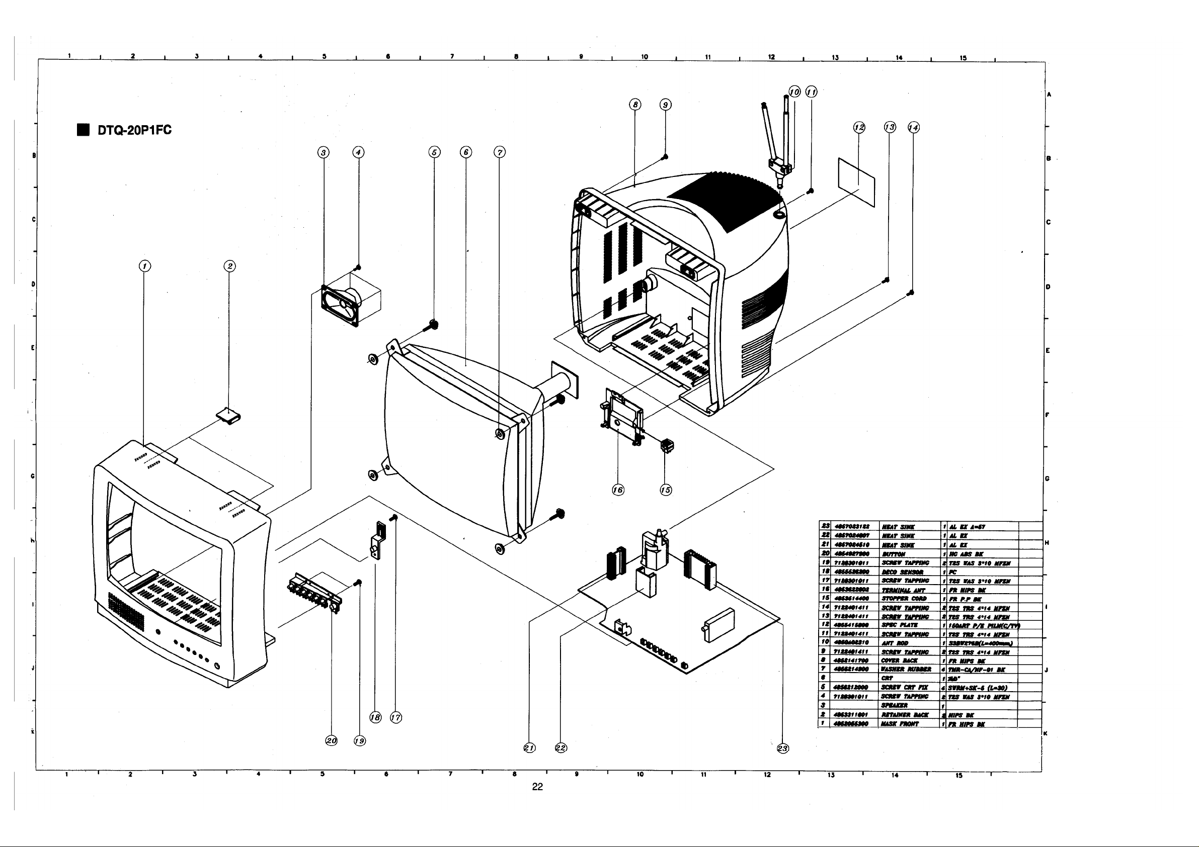
Page 33
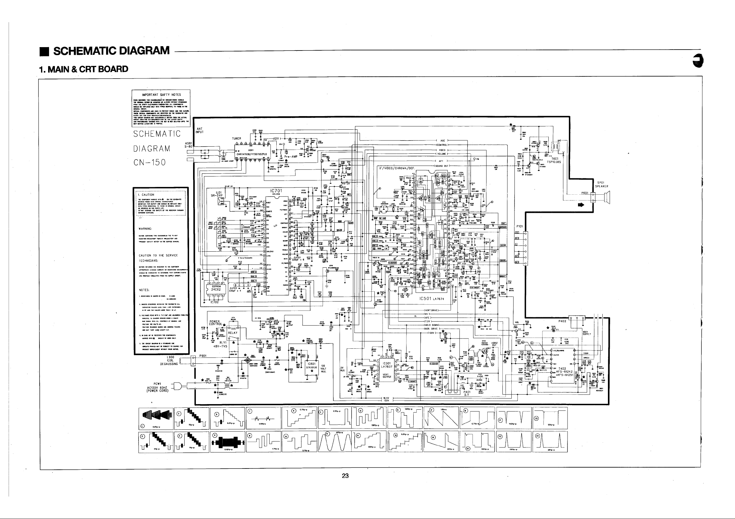
Page 34
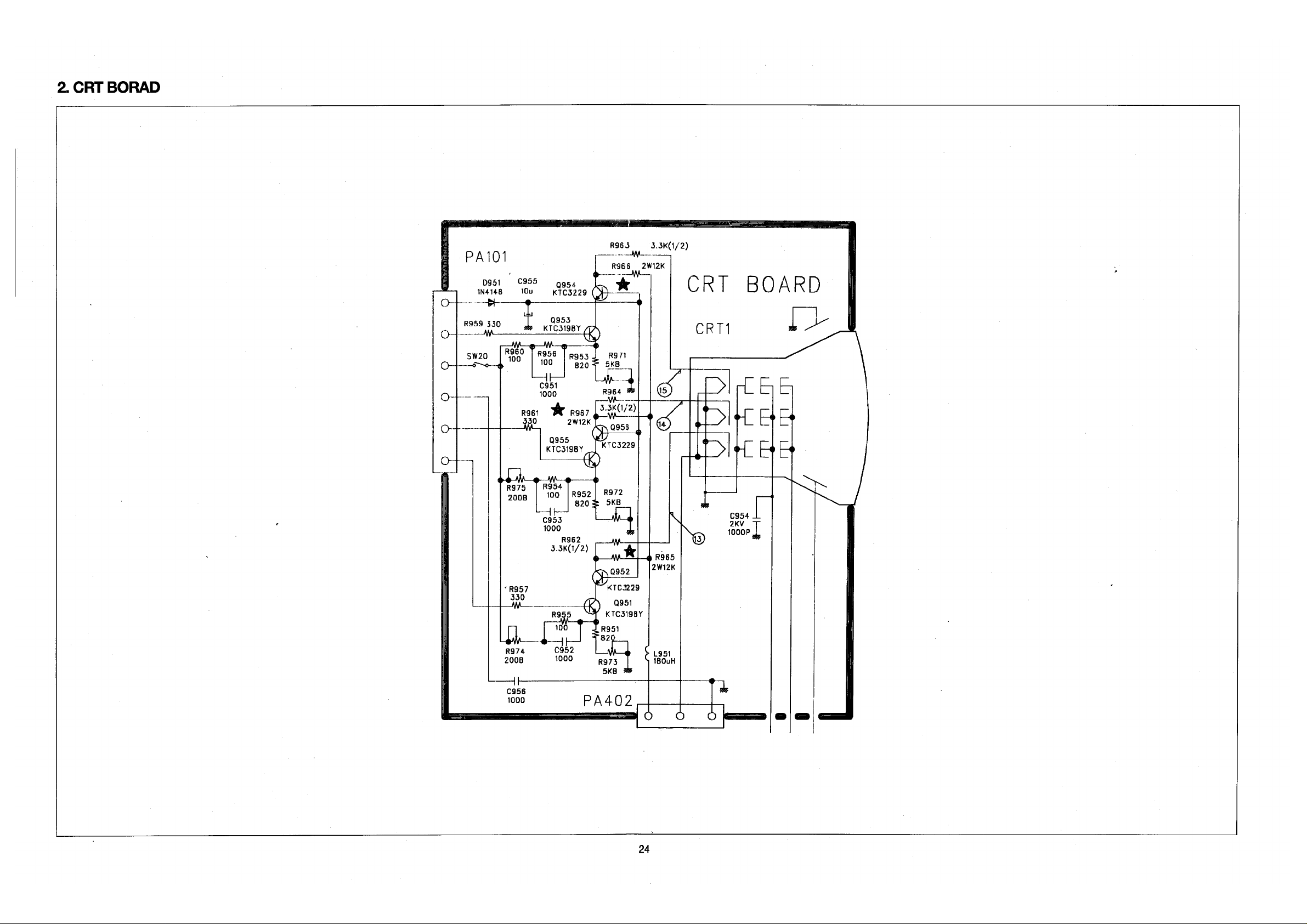
Page 35
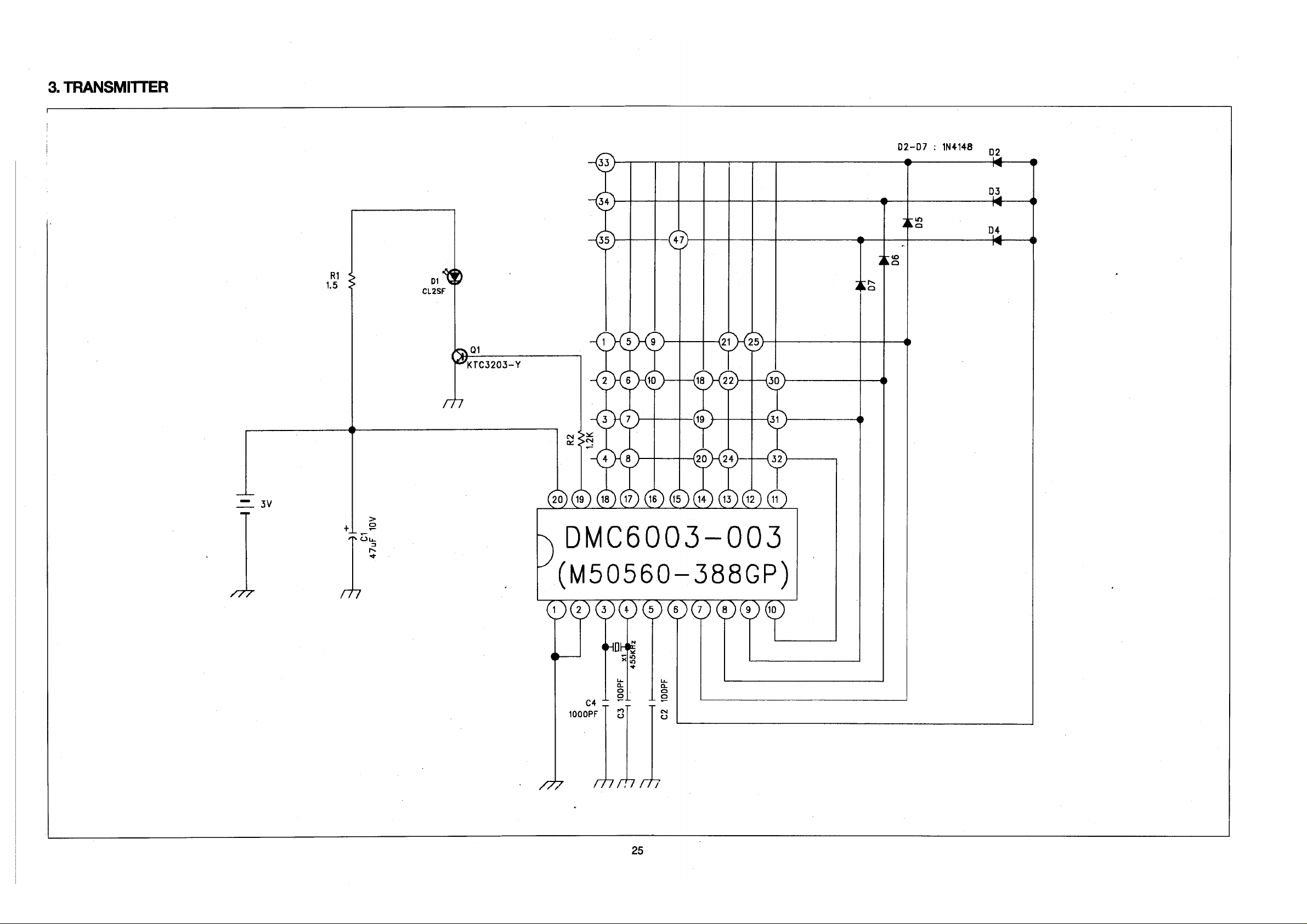
 Loading...