

Daewoo DTM-29U7Z SERIES, DTM-29U8Z SERIES, DTM-2881Z SERIES, DTM-28W8Z SERIES Service Manual

Service Manual
Colour Television 68 Cm / 66 Cm WIDE STEREO
CHASSIS : CP-820F
July. 2003
MODEL :
S/M No: TCP820FBF0
Specifications
DTM-29U7Z
**
DTM-29U8Z
**
DTM-2881Z
**
DTM-
28W8Z
**
SAMSUNG
29" FLAT : A68QCP893X925 28" FLAT : W66QDE993X912
LGPD
29" FLAT : A68ERF012X044 28" FLAT : W66ERF022X044
Antenna Impdeance
SYSTEM
Main Voltage
12W 8ohm x 2 EA
Power Consumption
Sound Output
Speaker
OSD Language
English, German, French, Italian, Spanish, Dutch, Swedish, Finnish,
Danish, Norwegian, Polish, Czech, Romanian, Hungarian
Tuning System
Tuner
Number of Program
Aux. Terminal
TOP(5 Page memory) & FLOF(7 Page memory)
- West option : English, German/Dutch/Flemish, French, Italian, Spanish/Portuguese, Swedish/Finnish/Danish,
Hungarian, Rumanian, Turkish
Remote Controller
Teletext
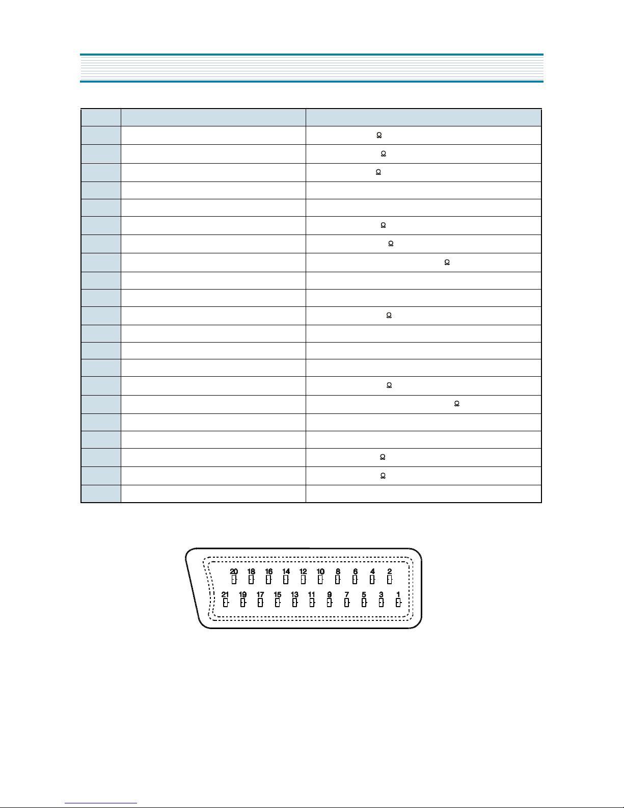
21 pin EURO-SCART jack (AV input, TV output, RGB input)
21 pin EURO-SCART jack (AV input, S-VHS input)
RCA type AV input jack
S-VHS jack
Headphone jack
R-22D06 with 2 "AAA" type batteries
75 ohm unbalanced input (Din Standard)
Frequency Synthesize(FS) Tuning System
UV1316/A(Philips), DT5-BF18D(Partsnics), TECC2949PG35W(S/S), EL2782-105-B(Siel)
100 programs
Stand-by mode : 3.0Watts
Normal operating mode : 110 Watts
10 + 10 Watts, 10% THD at RF 60% mod. (1kHz)
CRT
PAL/SECAM-B/G,D/K,PAL-I/I',SECAM-L/L' NTSC-3.58/4.43 (Play back)
230V AC, 50Hz
CP-820F
http : //svc.dwe .co.kr
Caution
: In this Manual, some parts can be changed for improving. their
performance without notice in the parts list. So, if you need the
latest parts information, please refer to PPL(Parts Price List)in
Service Information Center(http://svc.dwe.co.kr)
DAEWOO ELECTRONICS Corp.

1
TABLE OF CONTENTS
SAFETY INSTRUCTION .................................................................................................................. 2
SPECIFICATIONS ............................................................................................................................ 3
CIRCUIT BLOCK DIAGRAM ........................................................................................................... 4
ALIGNMENT INSTRUCTION ........................................................................................................... 5
SCHEMATIC DIAGRAM .................................................................................................................. 12
EXPLODED VIEW ............................................................................................................................ 14
PRINTED CIRCUIT BOARD ............................................................................................................ 18
SERVICE PARTS LIST .................................................................................................................... 21
APPENDIX (" Appendix is provided only by internet [http://svc.dwe.co.kr] ")
IC DESCRIPTION ............................................................................................................................. 1
IC DC VOLTAGE CHARTS .............................................................................................................. 18

2
SAFETY INSTRUCTION
WARNING
: Only competent service personnel may carry out work involving the testing or repair of this equipment
1. Excessive high voltage can prodece potentially hazardous X-RAY RADIATION. To avoid such hazards,
the high voltage must not exceed the specified limit.
The nominal value of the high voltage of this receiver is
29-31kv at max beam current. The high voltage must
not, under any circumstances, exceed 35kv. (33kv :
SAMSUNG CRT)
Each time a receiver require servicing, the high volt-
age should be checked. It is imprortant to use an accurate and reliable high voltage meter.
2. The only source of X-RAY Radiation in this TV receiver
is the picture tube. For continued X-RAY RADIATION
protection, the replacement tube must be exactly the
same type tube as specified in the parts list.
X-RAY RADIATION PRECAUTION
1. Potentials of high voltage are present when this
receiver is operating. Operation of the receiver outside
the cabinet or with the back board removed involves a
shock hazard from the receiver.
1) Servicing should not be attempted by anyone who is
not thoroughly familiar with the precautions necessary when working on high-voltage equipment.
2) Dischange the high potential of the picture tube
before handling the tube. The picture tube is highly
evacuated and if broken, glass fragments will be
violently expelled.
2. If any Fuse in this TV receiver is blown, replace it with
the FUSE specified in the Replacement Parts List.
3. When replacing a high wattage resistor ( oxide metal
film resistor ) in circuit board, keep the resistor 10mm
away from circuit board.
4. Keep wires away from high voltage or high temperature components.
5. This receiver must operate under AC230 volts, 50Hz.
NEVER connect to DC supply or any other power or
frequency.
SAFETY PRECAUTION
Many electrical and mechanical parts in this have
special safety-related characteristics. These characteristics are often passed unnoticed by a visual
inspection and the X-RAY RADIATION protection
afforded by them cannot necessarily be obtained by
using replacement components rated for higher voltage, wattage, etc. Replacement parts which have
these special safety characteristics are identified in
this manual and its supplements, electrical compo-
nents having such features are identified designated
symbol on the parts list.
Before replacing any of these components, read the
parts list in this manual carefully. The use of substitute
replacement parts which do not have the same safety
characterisitics as specifide in the parts list may create
X-RAY Radiation.
PRODUCT SAFETY NOTICE
3
PIN Signal Designation Matching Value
1 Audio Out (linked with 3)
0.5Vrms, Imp < 1 k (RF 60% MOD)
2 Audio In (linked with 6)
0.5Vrms, Imp < 10 k
3 Audio Out (linked with 1)
0.5Vrms, Imp < 1 k (RF 60% MOD)
4 Audio Earth
5 Blue Earth
6 Audio in (linked with 2)
0.5Vrms, Imp < 10 k (RF 60% MOD)
7 Blue in
0.7Vpp 2dB, Imp 75
8 Slow (Function) Switching
TV : 0-2V, PERI : 9.5 - 12V, Imp > 10 k
9 Green Earth
10 NC
11 Green In
0.7Vpp 2dB, Imp 75
12 NC
13 Red Earth
14 Rapid(Blanking) Switching Earth
15 Red In, C In
0.7Vpp 2dB, Imp 75
16 Rapid(Blanking) switching
Logic 0 : 0 - 0.4V, Logic 1 : 1 - 3V, Imp 75
17 Video Earth
18 Rapid Blanking Earth
19 Video Out
1Vpp 2dB, Imp 75
20 Video In, Y In
1Vpp 2dB, Imp 75
21 Common Earth
SPECIFICATIONS
+
-
+
-
+
-
+
-
+
-
4
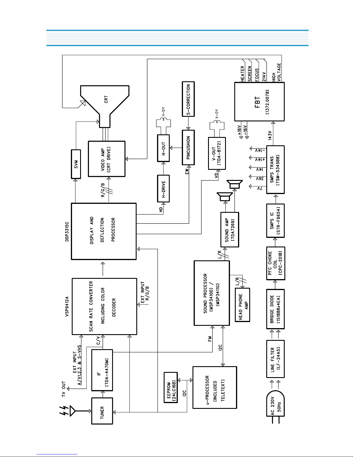
CIRCUIT BLOCK DIAGRAM
5
ALIGNMENT INSTRUCTIONS
User Remocon
1. R-22D06
TV................................TXTTV...................................TXT
VOLUME...............VOLUME
MENU.......................MENU
POWER.................POWER
DOWN ..................DOWN
(CURSOR LEFT)
PR UP..........................PAGE UP
(CURSOR UP)
VOLUME UP...........VOLUME UP
(CURSOR RIGHT)
PR DOWN..............PAGE DOWN
NORMAL .................... Not used
A V .............................. Not used
TXT ............................. Not used
Not used ...................... INDEX
Not used ...................... C
Zoom ..................Double Window
SOUND ....................... Not used
MODE
MUTE .......................... MUTE
(CURSOR DOWN)
Not used ....................... Size
Not used ....................... Y
EFFECT ....................... Not used
R-22D06
SLEEP...................Not used
Not used................CANCEL
Not used................... HOLD
RECALL...............SUBPAGE
STILL......................REVEAL
Not used ..........................R
Not used ..........................G
PR ......................... PAGE
NUMBER NUMBER
0-9 0-9
6
* How to Enter the “ Service Mode ” with user remocon.
1) Set the TV Pr 91
2) Sharpness “ MIN “ control.
3) Push the Red, Green, Menu buttons in regular sequency within 5 seconds after setting TV power off.
4) You can see the Menu of “ service mode “ on the screen.
5) The PR UP/DOWN buttons on the remote controller are used to move the selection bar up or down the Menus.
6) The VOL UP/DOWN buttons on the remote controller are used to adjust levels.
7) If you want to exit from “ Service Mode “ then power the TV off.
- You can see the SVC Menu by OSD in TV set.
ALIGNMENT INSTRUCTIONS
Tuner is
Flat Option
Svm SVG
Svm SVD
Svm SVDEL
Svm SVCOR
Bcl Thres
Bcl Tc
Bcl Gain
Nor1 Bright
Nor1 Cont
Nor1 Color
Nor1 Sharp
Nor1 Tint
Nor2 Bright
Nor2 Cont
Nor2 Color
Nor2 Sharp
Nor2 Tint
Dolby3411
Phi
NO
020
001
013
012
430
250
511
038
058
038
032
032
038
038
038
032
032
NO
Osd Contrast
Osd Bright
Text Gain
Tilt Option
Transparent
Vertical angle
Vertical bow
380
000
NO
NO
NO
000
000
V. Slope
V. Center
V. Size
S. Curve
H. Center
H. Width
EW. Para
EW. Cor Top
EW. Cor Low
EW.Sym
R. Bias
G. Bias
B. Bias
R. Drive
G. Drive
B. Drive
G2 Adjust
Sub bright
Double TEXT
Wide Option
-002
887
091
035
-325
088
-068
015
015
-013
330
330
330
370
370
370
000
000
514
NO
SVC v1
CP-820
7
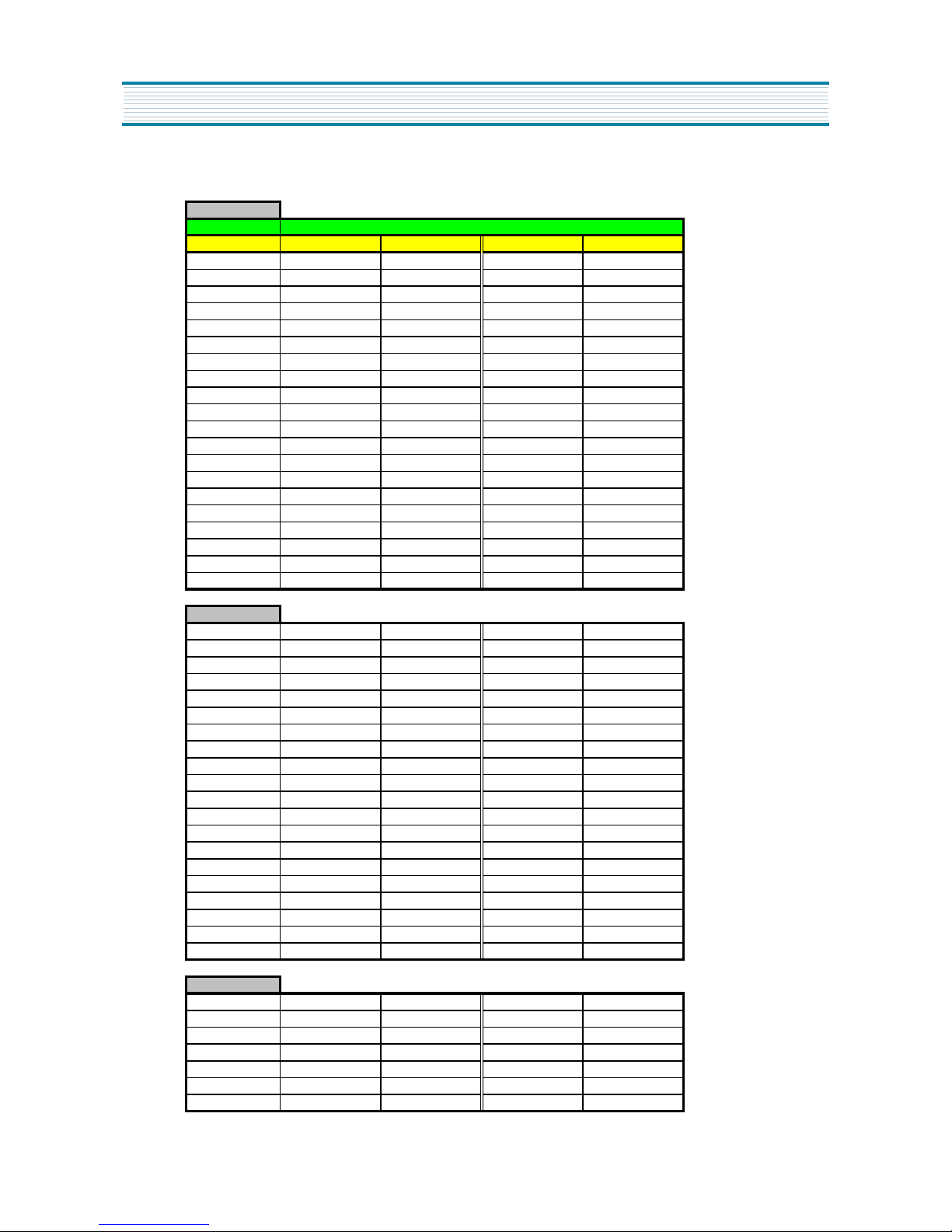
ALIGNMENT INSTRUCTIONS
Alignment Instructions for
CP-820F
Chassis
1PAGE
CHASSIS
MODEL
DTM-28W8ZLF DTM-28W8ZLS DTM-29U8ZLF DTM-29U8ZLS
V. Slope -010 -020 -010 -020
V. Center 886 880 855 790
V.Size 040 080 050 088
S.Curve 020 030 020 030
H.Center -331 -330 -336 -330
H.Width 071 055 035 030
EW.Para -075 -060 -107 -088
EW.Cor Top 011 011 013 016
EW.Cor Low 017 018 010 025
EW. Sym -030 -020 -030 -025
R Bias 330 350 330 330
G Bias 330 350 330 330
B Bias 330 350 330 330
R Drive 370 400 370 370
G Drive 370 400 370 370
B Drive 370 400 370 370
G2 Adjust 000 000 000 000
Sub Bright 015 015 015 015
Double TEXT 000 000 000 000
Wide Option
YES
YESNONO
2PAGE
Tuner Is DWE DWE DWE DWE
Flat Option YES YES YES YES
Svm SVG 010 010 010 010
Svm SVD 002 002 002 002
Svm SVDEL 010 007 010 007
Svm SVCOR 008 007 008 007
Bcl Thres 530 550 530 550
Bcl Tc 250 250 250 250
Bcl Gain 511 511 511 511
Nor1 Bright 038 045 038 038
Nor1 Cont 058 058 058 058
Nor1 Color 040 040 040 040
Nor1 Sharp 032 032 032 032
Nor1 Tint 032 032 032 032
Nor2 Bright 042 042 042 042
Nor2 Cont 038 038 038 038
Nor2 Color 038 038 038 038
Nor2 Sharp 028 028 028 028
Nor2 Tint 032 032 032 032
Dolby 3411
YES
YES
YES
YES
3PAGE
Osd Contrast 380 380 380 380
Osd Bright 000 000 000 000
Text Gain NO NO NO NO
Tilt Option NO NO NO NO
Transparent NO NO NO NO
Ver. Angle 000 -772 000 -772
Ver. Bow
000
-772
000
-772
CP-820F
8
AFT
Standard B/G, D/K, I and L
1) Set a Signal Generator with
- RF FREQUENCY = 38.9 MHz,
- RF OUTPUT LEVEL = 80 5dBuV
- Pattern = Color Bar
- System = PAL-B/G
2) Connect the Signal Generator RF Output to TP2 (Tuner IF Output).
There must be no signal input to the tuner.
3) Set the L103 to TP1(I101, #22) with DC Voltage to 2.5V 0.1V
AGC
1) Set a Pattern Generator with RF LEVEL 63dBuV(Philips, Siel, S/S) / 70dBuV(Partsnic)",
RF Frequency 487.25MHz(23CH), Pattern Color Bar.
+
-
+
-
ALIGNMENT INSTRUCTIONS
2) Connect a OSCILLOSCOPE PROBE to P101 (TUNER AGC INPUT).
3) Set the RBO2 to P101(Tuner AGC Input) with DC Voltage to 3.0V 0.1V
SCREEN (G2)
1) Set a Pattern Generator with - RF Frequency : 210.25MHz (10CH)
- Pattern : RETMA
2) Select the “ G2” in Menu
3) And a Horizontal Line will appear on the screen.
4) Adjust the SCREEN VOLUME on FBT barely to see the Horizontal Line.
5) Press the PR UP/DOWN keys to finish the SCREEN adjustment.
FOCUS
1) Apply a RETMA PATTERN signal.
2) Adjust the FOCUS VOLUME on FBT to obtain optimal resolution.
GEOMETRY
1. VERTICAL SLOPE ( Fixed : Adjust if need be )
1) Apply a RETMA PATTERN Signal.
2) Set the TV to Normal I mode.
3) Adjust the higher semicircle and the lower semicircle to be the same, with the V.Slope
by volume Up/Down keys.
2. VERTICAL CENTER
1) Apply a RETMA PATTERN Signal.
2) Set the TV to Normal I mode.
3) Adjust the center of the picture with the V.Center by volume Up/Down keys.
+
-
9
3. VERTICAL SIZE
* The VERTICAL CENTER adjustment has to be done in advance.
1) Apply a RETMA PATTERN Signal.
2) Set the TV to Normal I mode.
3) Adjust the VERTICAL SIZE of the picture with the select V.size by
volume UP/DOWN keys.
4. VERTICAL S-CORRECTION ( Fixed : Adjust if need be )
1) Apply a CROSSHATCH PATTERN Signal.
2) Adjust the S-CORRECTION to obtain the same distance between
horizontal lines with the S.Curve by volume UP/DOWN keys.
5. HORIZONTAL CENTER
1) Apply a RETMA PATTERN Signal.
2) Adjust picture centering with the select H.Center by volume UP/DOWN keys.
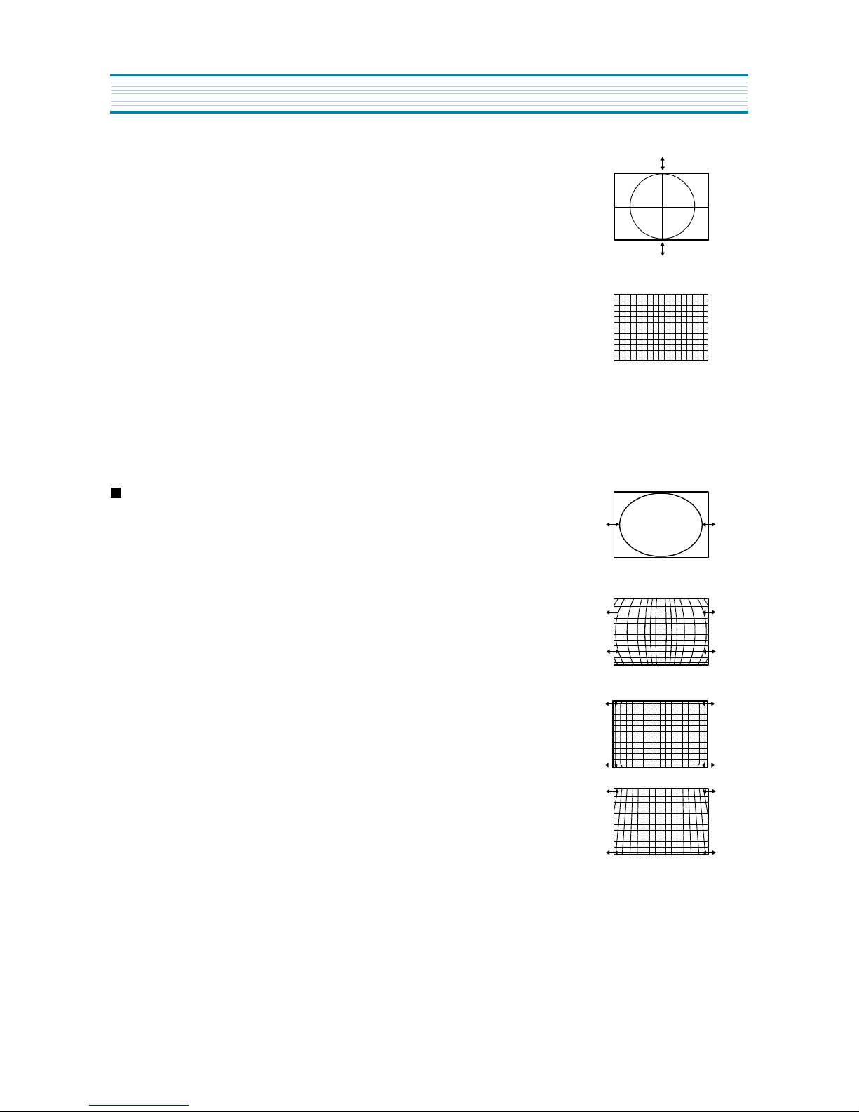
EW
1. WIDTH
1) Apply a RETMA PATTERN Signal.
2) Adjust the horizontal width to make a perfect circle with the select H.Width
by volume UP/DOWN keys.
2. PARA
1) Apply a CROSSHATCH PATTERN Signal.
2) Adjust the vertical line to straight with the select E.W Para by volume
UP/DOWN keys.
3. CORNER ( Fixed : Adjust if need be )
1) Apply a CROSSHATCH PATTERN Signal.
2) Adjust the vertical line to straight with the select EW.Cor T by volume
UP/DOWN keys.
4. SYMMETRY ( Fixed : Adjust if need be )
1) Apply a CROSSHATCH PATTERN Signal.
2) Adjust the symmetrical balance to be suitable with the select EW Sym by
volume UP/DOWN keys.
ALIGNMENT INSTRUCTIONS

10
WHITE BALANCE
1. RGB Reference R
2. Beam Reference LOW ( 288, 301 : 10Cd/ )
HIGH ( 288, 301 : 100Cd/ )
3. Adjust G, B Gain with select Menu G,B of BIAS, DRIVE of select Menu so that R, G, B Bars
are on the center position of the analog meter. If R Analog meter is not on center, control
the Brightness +/- of user Remocon so as R Analog meter to be on the center position.
SUB BRIGHT
1. Pattern : Retma
2. Adjust the SUB BRIGHT with the select Sub Bri by volume UP/DOWN keys.
so that only H-Center parts of picture can be seen.
DOUBLE TEXT CENTER
1. Pattern : Pattern RED
2. Select Menu
3. Select DT in SVC menu time to see the Double Text Picture.
( Left : RF Picture, Right : Text Picture )
4. Change the Double Text control keys volume UP/DOWN keys so that the left edge of text
picture concur with the right edge of RF picture.
WIDE MODE
1. Locate the cursor on ‘ Wide’ in SVC Menu.
2. ‘ Yes’ changes the display to 16:9 mode.
3. ‘ No’ change the display to 4:3 mode.
m
2
m
2
ALIGNMENT INSTRUCTIONS
FLAT MODE
1. Locate the cursor on ‘ FLAT’ in SVC Menu.
2. ‘ Yes’ changes the display to FLAT CRT mode.
3. ‘ No’ change the display to Normal CRT mode.
TUNER SELECTION
1. DWE : Partsnic Tuner S/S Tuner
2. PHI : Philips Tuner
3. SIE : Siel Tuner

11
SVM (Scan Velocity Modulation)
1. SVM SVG : SVM Gain
2. SVM SVD : SVM Differentiator delay (0 = filter off)
3. SVM SVDEL : Delay of SVMOUT in steps of 12.5nS
2. SVM SVCOR : SVM coring value
ALIGNMENT INSTRUCTIONS
BCL (Beam Current Limit)
1. BCL Thres : BCL threshold current
2. BCL TC : BCL time constant
3. BCL Gain : BCL loop Gain
12
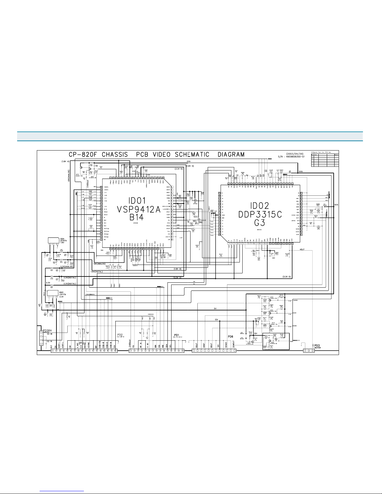
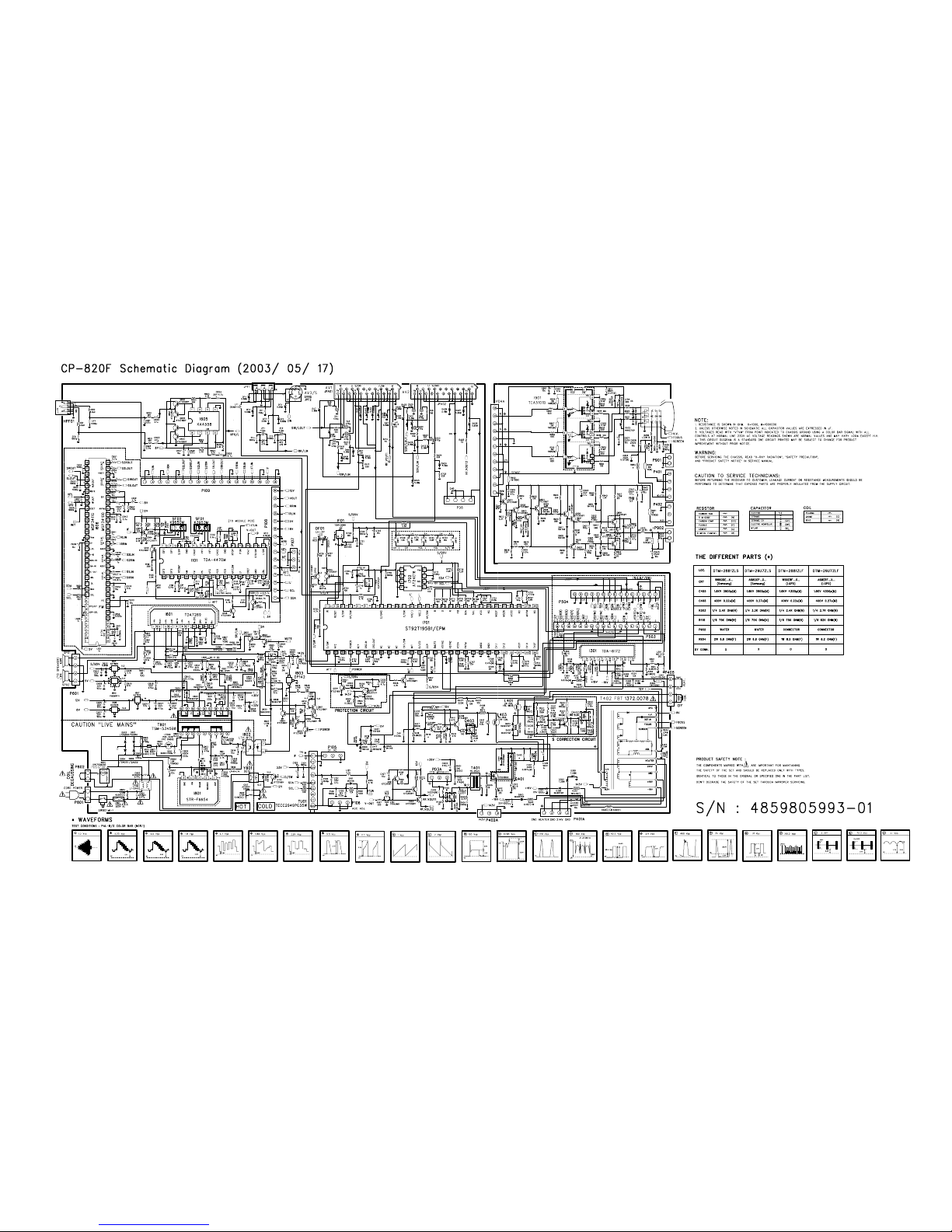
SCHEMATIC DIAGRAM
13
14
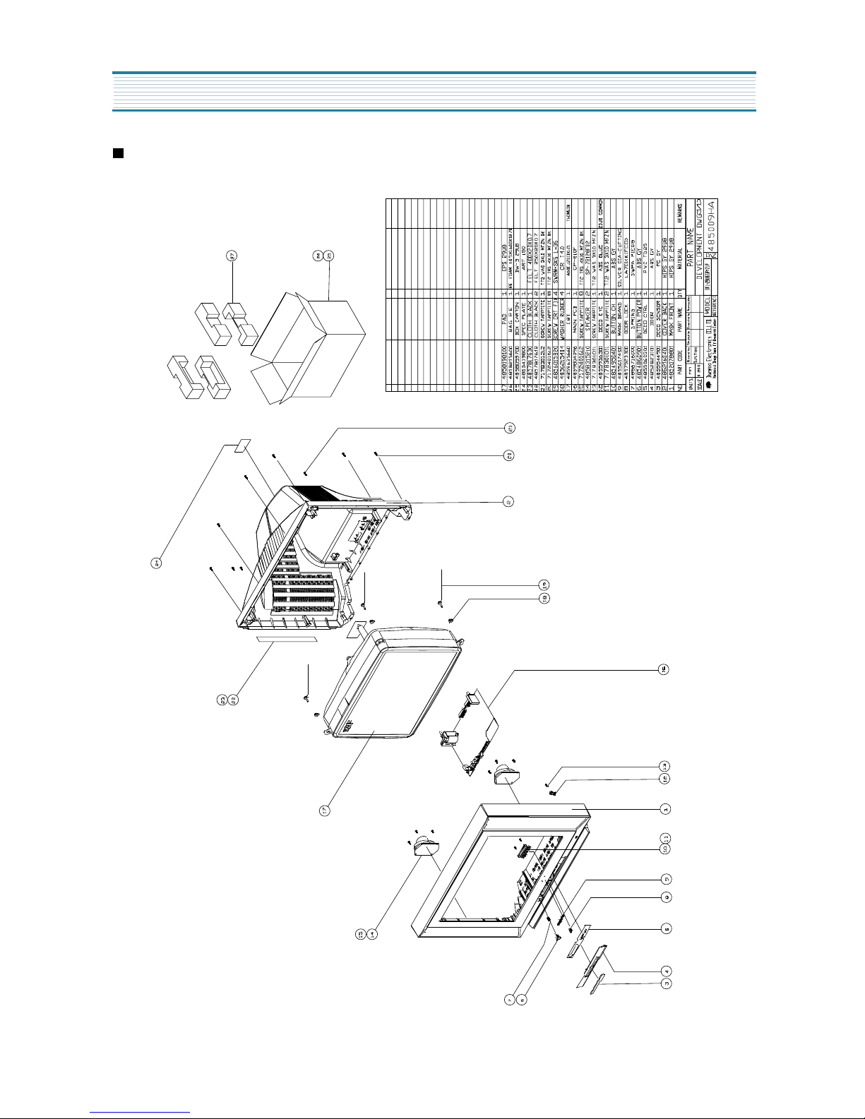
EXPLODED VIEW
DTM-29U7ZLS/DTM-29U7ZZS
 Loading...