

Daewoo DTL-2950K, DTL-2950, DTL-2950GB Service Manual

Caution
: In this Manual, some parts can be changed for improving. their
performance without notice in the parts list. So, if you need the
latest parts information, please refer to PPL(Parts Price List)in
Service Information Center.
Service Manual
COLOR Television
CHASSIS :
Model :
CP-650
DTL-2950
DTL-2950K
DTL-2950GB
P/N : TCP650FEF0
APR.2006

CP-650 Service Manual
DTV R&D Europe
1
CONTENTS
DOCUMENT HISTORY.................................................................................................................3
1 MAIN FEATURES..................................................................................................................4
1.1 SPECIFICATIONS ..........................................................................................................4
1.1.1 GENERAL................................................................................................................4
1.1.2 EURO-SCART 1 (21 Pin).........................................................................................4
1.1.3 EURO-SCART 2 (21 Pin).........................................................................................5
1.2 CHANNEL/FREQUENCY TABLE...................................................................................6
2 SAFETY INSTRUCTION........................................................................................................9
3 ALIGNMENT INSTRUCTIONS.............................................................................................10
3.1 MICROCONTROLLER CONFIGURATION : SERVICE MODE....................................10
3.2 SERVICE MODE NAVIGATION....................................................................................10
3.3 MICROCONTROLLER CONFIGURATION : OPTION BITS ........................................11
3.4 OPTION 1......................................................................................................................11
3.5 OPTION 2......................................................................................................................11
3.6 NVM DEFAULT SETTING ............................................................................................12
3.7 TV SET ALIGNMENT....................................................................................................14
3.7.1 G2 ALIGNMENT.....................................................................................................14
3.7.2 WHITE BALANCE..................................................................................................14
3.7.3 FOCUS...................................................................................................................14
3.7.4 VERTICAL GEOMETRY ........................................................................................14
3.7.5 HORIZONTAL PICTURE CENTRING....................................................................14
3.7.6 EAST / WEST CORRECTION................................................................................14
3.7.7 AGC........................................................................................................................15
4 IC DESCRIPTION................................................................................................................. 16
4.1 UOC
III
SERIES..............................................................................................................16
4.1.1 IC MARKING AND VERSION ................................................................................16
4.2 TDA8946J STEREO AUDIO AMPLIFIER.....................................................................24
4.2.1 FEATURES............................................................................................................25
4.3 TDA8358J VERTICAL AMPLIFIER..............................................................................27
4.3.1 TDA8358J ..............................................................................................................27
4.4 TDA6107AJF ................................................................................................................29
4.4.1 Features.................................................................................................................29
4.4.2 Pin description........................................................................................................29
4.5 24WC16 - 16 KB EEPROM...........................................................................................30
4.6 STR – W6754................................................................................................................31
4.6.1 GENERAL DESCRIPTION.....................................................................................31
4.6.2 FEATURES............................................................................................................31
4.6.3 BLOCK DIAGRAM .................................................................................................31
4.6.4 PIN DESCRIPTION................................................................................................32
4.6.5 MOSFET ELECTRICAL CHARACTERISTICS.......................................................32
4.6.6 ELECTRICAL CHARACTERISTICS.......................................................................33
5 CIRCUIT DESCRIPTION......................................................................................................34
5.1 BLOCK DIAGRAM........................................................................................................34
5.2 FUNCTIONAL DESCRIPTION OF VIDEO PROCESSOR............................................35
5.2.1 Vision IF amplifier................................................................................................... 35
5.2.2 QSS sound circuit...................................................................................................35
5.2.3 FM demodulator.....................................................................................................35
5.2.4 Audio input selector and volume contro..................................................................36

CP-650 Service Manual
DTV R&D Europe
2
5.2.4.1 STEREO AND AV STEREO VERSIONS............................................................36
5.2.4.2 MONO VERSIONS.............................................................................................36
5.2.5 CVBS and Y/C input signal selection......................................................................36
5.2.5.1 ALL VERSIONS..................................................................................................36
5.2.6 Synchronisation circuit............................................................................................37
5.2.7 Horizontal and vertical drive...................................................................................38
5.2.8 Chroma, luminance and feature processing...........................................................38
5.2.9 Colour decoder.......................................................................................................39
5.2.10 RGB output circuit ..................................................................................................40
5.2.11 I2C-BUS USER INTERFACE DESCRIPTION........................................................42
5.3 GENERAL DESCRIPTION OF THE TV SOUND OF SOUND PROCESSOR ..............42
5.3.1 Supported standards..............................................................................................43
5.4 FUNCTIONAL DESCRIPTION SOUND PROCESSOR................................................44
5.4.1 The UOC III TV Sound Concept.............................................................................44
5.4.2 Functional Overview Of the digital controller sound part ........................................45
5.4.3 Demodulator and decoder......................................................................................46
6 SERVICE PARTS LIST........................................................................................................49
6.1 DTL-2950 ......................................................................................................................49
7 EXPLODED VIEW................................................................................................................68
7.1 DTL-2950 ......................................................................................................................68
8 PRINTED CIRCUIT BOARD ................................................................................................69
8.1 PCB MAIN(4859812493)...............................................................................................69
8.2 PCB SUB)4859816424)................................................................................................ 70
9 SCHEMATIC DIAGRAM ......................................................................................................71

CP-650 Service Manual
DTV R&D Europe
3
DOCUMENT HISTORY
VERSION DATE COMMENTS
V1.00 28/03/06 Creation of document (Author JS KIM) for project CP650 50Hz SLIM TV.
CP-650 Service Manual
DTV R&D Europe
4
1 MAIN FEATURES
1.1 SPECIFICATIONS
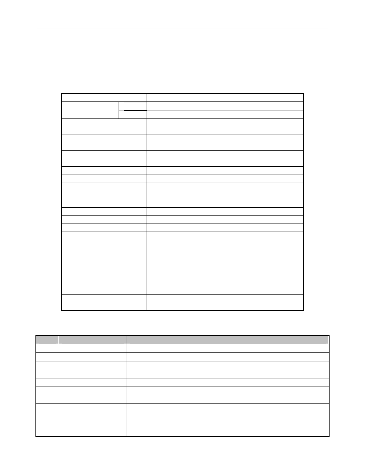
1.1.1 GENERAL
TV standard PAL - SECAM B/G D/K, PAL I/I, SECAM L/L’
Tuner PAL, SECAM Colour system
AV PAL, SECAM, PAL 60, NTSC M, NTSC 4.43
Sound system NICAM B/G, I, D/K, L,
FM 2Carrier B/G, D/K
Power
consumption
105W
Sound Output
Power
7W x 2 (at 60% mod, 10%THD)
Speaker 12W 8 ohm x2
Teletext system 10 pages memory FASTEXT (FLOF or TOP)
Aerial input 75 ohm unbalanced
Channel coverage Off-air channels, S-cable channels and hyperband
Tuning system frequency synthesiser tuning system
Visual screen size 68cm
Channel indication On Screen Display
Program Selection 100 programmes
Aux. terminal EURO-SCART 1 : Audio / Video In and Out, R/G/B
In, Slow and Fast switching.
EURO-SCART 2 : Audio / Video In and Out, SVHS
In.
AV3 : Audio-Video Jack on front of cabinet.
Headphone jack (3.5 mm) on front of cabinet
SVHS3 : Jack on side of cabinet – sound input
common with AV3.
Remote Control
Unit
R-49C10
1.1.2 EURO-SCART 1 (21 Pin)
Pin Signal Description Matching value
1 Audio Output Right
0.5 Vrms, Impedance < 1 kΩ, ( RF 54% Mod )
2 Audio Input Right
0.5 Vrms, Impedance > 10 kΩ
3 Audio Output Left
0.5 Vrms, Impedance < 1 kΩ, ( RF 54% Mod )
4 Audio Earth
5 Blue Earth
6 Audio Input Left
0.5 Vrms, Impedance > 10 kΩ
7 Blue Input
0.7 Vpp ±0.1V, Impedance 75Ω
8 Slow Switching TV : 0 to 2V, AV 16/9 : 4.5 to 7V, AV 4/3 : 9.5 to 12V , Impedance
> 10 kΩ
9 Green Earth
10 N.C.
CP-650 Service Manual
DTV R&D Europe
5
11 Green Input
0.7 Vpp ± 0.1V, Impedance 75Ω
12 N.C.
13 Red Earth
14 Blanking Earth
15 Red Input
0.7 Vpp ± 0.1V, Impedance 75Ω
16 Fast Switching
0 to 0.4V : Logic “0”, 1 to 3V : Logic “1”, Impedance 75Ω
17 Video Out Earth
18 Video In Earth
19 Video Output
1 Vpp ± 3dB, Impedance 75Ω
20 Video Input
1 Vpp ± 3dB, Impedance 75Ω
21 Common Earth
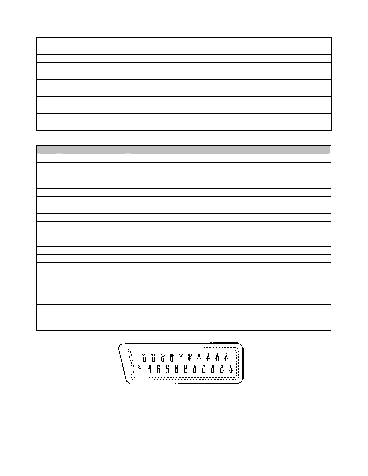
1.1.3 EURO-SCART 2 (21 Pin)
Pin Signal Description Matching value
1 Audio Output Right
0.5 Vrms, Impedance < 1 kΩ, ( RF 54% Mod )
2 Audio Input Right
0.5 Vrms, Impedance > 10 kΩ
3 Audio Output Left
0.5 Vrms, Impedance < 1 kΩ, ( RF 54% Mod )
4 Audio Earth
5 Earth
6 Audio Input Left
0.5 Vrms, Impedance > 10 kΩ
7 N.C.
8 N.C.
9 N.C.
10 N.C.
11 N.C.
12 N.C.
13 Earth
14 Earth
15 Chroma Input
± 3dB for a luminance signal of 1 Vpp
16 N.C.
17 Earth
18 Video In Earth
19 Video Output
1 Vpp ± 3dB, Impedance 75Ω ( Monitor output )
20 Video Input, Y In.
1 Vpp ± 3dB, Impedance 75Ω
21 Common Earth
CP-650 Service Manual
DTV R&D Europe
6
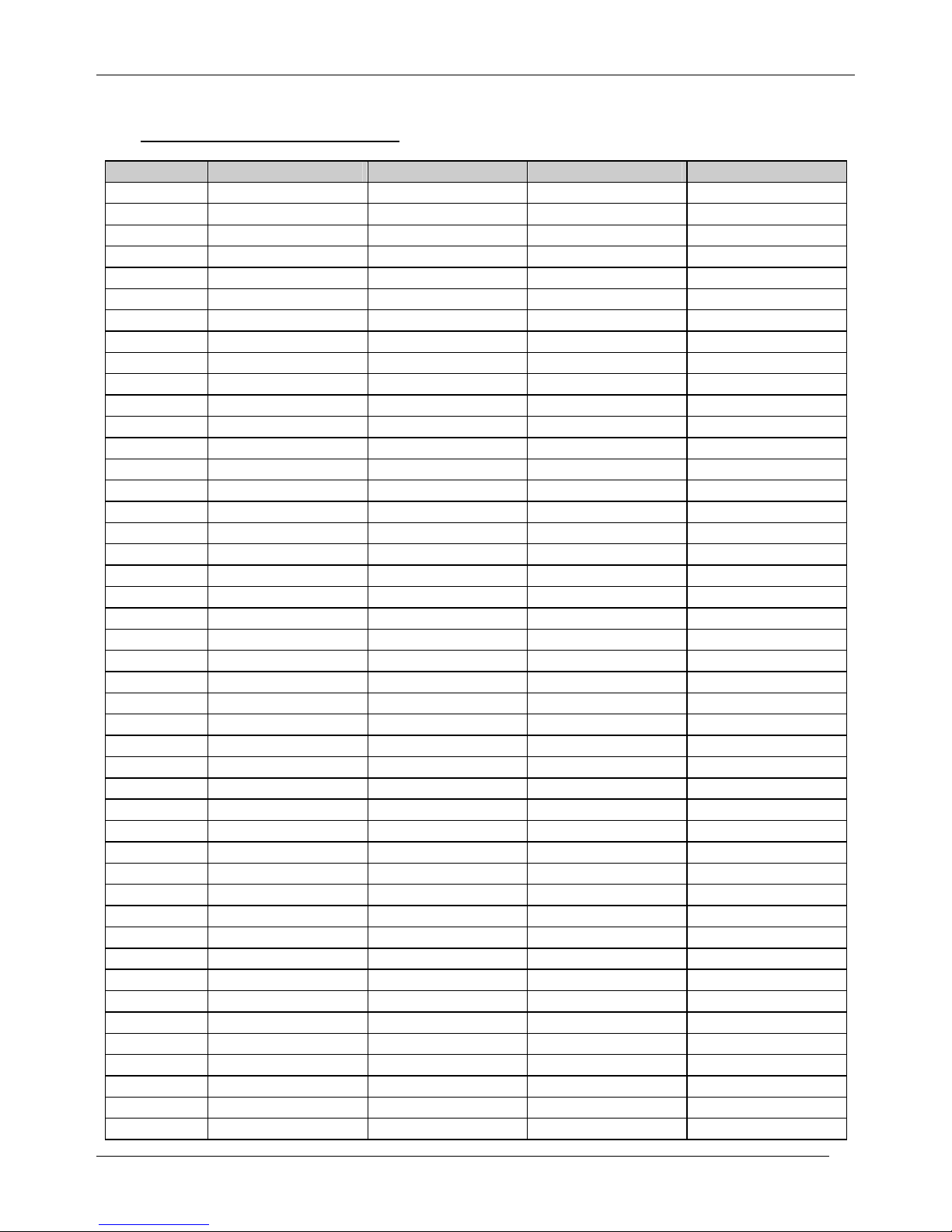
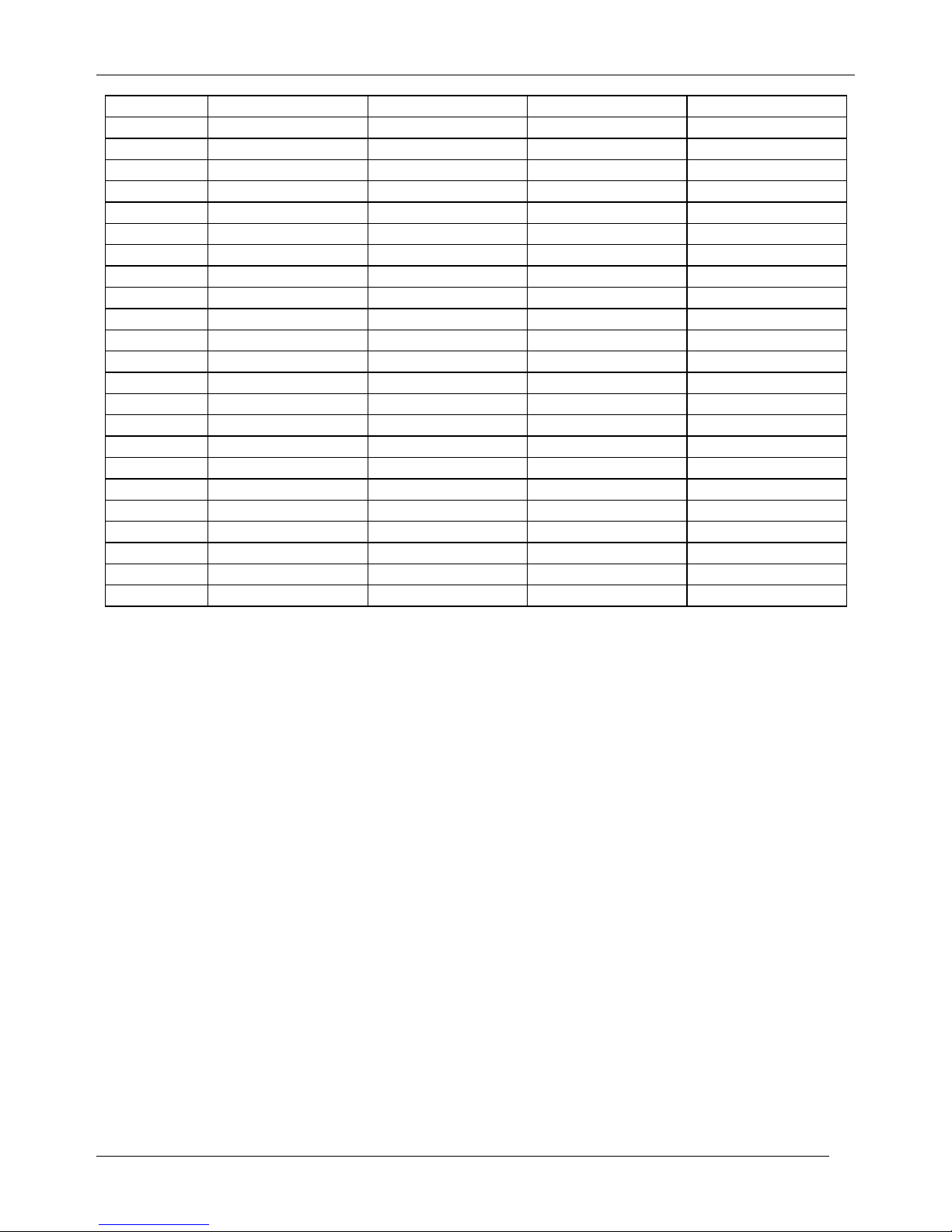
1.2 CHANNEL/FREQUENCY TABLE
CHANNEL EUROPE CCIR FRANCE GB(IRELAND) EAST OIRT
C01
46.25 - 45.75 49.75
C02
48.25 55.75 (L') 53.75 59.25
C03
55.25 60.5 (L') 61.75 77.25
C04
62.25 63.75 (L') 175.25 85.25
C05
175.25 176.00 183.25 93.25
C06
182.25 184.00 191.25 175.25
C07
189.25 192.00 199.25 183.25
C08
196.25 200.00 207.25 191.25
C09
203.25 208.00 215.25 199.25
C10
210.25 216.00 223.25 207.25
C11
217.25 189.25 (LUX) 231.25 215.25
C12
224.25 69.25 (L') 239.25 223.25
C13
53.75 76.25 (L') 247.25 -
C14
- 83.25 (L') 49.75 -
C15
82.25 90.25 57.75 -
C16
- 97.25 65.75 -
C17
183.75 - 77.75 -
C18
192.25 - 85.75 -
C19
201.25 - - -
C20
- - - -
C21
471.25 471.25 471.25 471.25
C22
479.25 479.25 479.25 479.25
C23
487.25 487.25 487.25 487.25
C24
495.25 495.25 495.25 495.25
C25
503.25 503.25 503.25 503.25
C26
511.25 511.25 511.25 511.25
C27
519.25 519.25 519.25 519.25
C28
527.25 527.25 527.25 527.25
C29
535.25 535.25 535.25 535.25
C30
543.25 543.25 543.25 543.25
C31
551.25 551.25 551.25 551.25
C32
559.25 559.25 559.25 559.25
C33
567.25 567.25 567.25 567.25
C34
575.25 575.25 575.25 575.25
C35
583.25 583.25 583.25 583.25
C36
591.25 591.25 591.25 591.25
C37
599.25 599.25 599.25 599.25
C38
607.25 607.25 607.25 607.25
C39
615.25 615.25 615.25 615.25
C40
623.25 623.25 623.25 623.25
C41
631.25 631.25 631.25 631.25
C42
639.25 639.25 639.25 639.25
C43
647.25 647.25 647.25 647.25
C44
655.25 655.25 655.25 655.25
C45
663.25 663.25 663.25 663.25

CP-650 Service Manual
DTV R&D Europe
7
C46
671.25 671.25 671.25 671.25
C47
679.25 679.25 679.25 679.25
C48
687.25 687.25 687.25 687.25
C49
695.25 695.25 695.25 695.25
C50
703.25 703.25 703.25 703.25
C51
711.25 711.25 711.25 711.25
C52
719.25 719.25 719.25 719.25
C53
727.25 727.25 727.25 727.25
C54
735.25 735.25 735.25 735.25
C55
743.25 743.25 743.25 743.25
C56
751.25 751.25 751.25 751.25
C57
759.25 759.25 759.25 759.25
C58
767.25 767.25 767.25 767.25
C59
775.25 775.25 775.25 775.25
C60
783.25 783.25 783.25 783.25
C61
791.25 791.25 791.25 791.25
C62
799.25 799.25 799.25 799.25
C63
807.25 807.25 807.25 807.25
C64
815.25 815.25 815.25 815.25
C65
823.25 823.25 823.25 823.25
C66
831.25 831.25 831.25 831.25
C67
839.25 839.25 839.25 839.25
C68
847.25 847.25 847.25 847.25
C69
855.25 855.25 855.25 855.25
C70
863.25 863.25 863.25 863.25
C71
69.25 - - -
C72
76.25 - - -
C73
83.25 - - -
C74
90.25 - - -
C75
97.25 - - -
C76
59.25 - - -
C77
93.25 - - -
S01
105.25 104.75 103.25 105.25
S02
112.25 116.75 111.25 112.25
S03
119.25 128.75 119.25 119.25
S04
126.25 140.75 127.25 126.25
S05
133.25 152.75 135.25 133.25
S06
140.25 164.75 143.25 140.25
S07
147.25 176.75 151.25 147.25
S08
154.25 188.75 159.25 154.25
S09
161.25 200.75 167.25 161.25
S10
168.25 212.75 - 168.25
S11
231.25 224.75 - 231.25
S12
238.25 236.75 - 238.25
S13
245.25 248.75 255.25 245.25
S14
252.25 260.75 263.25 252.25
S15
259.25 272.75 271.25 259.25
S16
266.25 284.75 279.25 266.25
S17
273.25 296.75 287.25 273.25
CP-650 Service Manual
DTV R&D Europe
8
S18
280.25 136.00 295.25 280.25
S19
287.25 160.00 303.25 287.25
S20
294.25 - - 294.25
S21
303.25 303.25 - 303.25
S22
311.25 311.25 311.25 311.25
S23
319.25 319.25 319.25 319.25
S24
327.25 327.25 327.25 327.25
S25
335.25 335.25 335.25 335.25
S26
343.25 343.25 343.25 343.25
S27
351.25 351.25 351.25 351.25
S28
359.25 359.25 359.25 359.25
S29
367.25 367.25 367.25 367.25
S30
375.25 375.25 375.25 375.25
S31
383.25 383.25 383.25 383.25
S32
391.25 391.25 391.25 391.25
S33
399.25 399.25 399.25 399.25
S34
407.25 407.25 407.25 407.25
S35
415.25 415.25 415.25 415.25
S36
423.25 423.25 423.25 423.25
S37
431.25 431.25 431.25 431.25
S38
439.25 439.25 439.25 439.25
S39
447.25 447.25 447.25 447.25
S40
455.25 455.25 455.25 455.25
S41
463.25 463.25 463.25 463.25

CP-650 Service Manual
DTV R&D Europe
9
2 SAFETY INSTRUCTION
WARNING: Only competent service personnel may carry out work involving the testing or repair
of this equipment.
X-RAY RADIATION PRECAUTION
1. Excessive high voltage can produce potentially hazardous X-RAY RADIATION. To avoid
such hazards, the high voltage must not exceed the specified limit. The nominal value of the high
voltage of this receiver is 28.5KV at max beam current. The high voltage must not, under any
circumstances, exceed 30 KV. Each time a receiver requires servicing, the high voltage should
be checked. It is important to use an accurate and reliable high voltage meter.
2. The only source of X-RAY Radiation in this TV receiver is the picture tube. For continued
X-RAY RADIATION protection, the replacement tube must be exactly the same type tube as
specified in the parts list.
SAFETY PRECAUTION
Potentials of high voltage are present when this receiver is operating. Operation of the receiver
outside the cabinet or with the back board removed involves a shock hazard from the receiver.
Servicing should not be attempted by anyone who is not thoroughly familiar with the precautions
necessary when working on high voltage equipment.
Discharge the high potential of the picture tube before handling the tube. The picture tube is
highly evacuated and if broken, glass fragments will be violently expelled.
If any Fuse in this TV receiver is blown, replace it with the FUSE specified in the Replacement
Parts List.
When replacing a high wattage resistor (metal oxide film resistor) in the circuit board, keep the
resistor 10 mm away from circuit board.
Keep wires away from high voltage or high temperature components.
This receiver must operate under AC 230 volts, 50 Hz. NEVER connect to a DC supply or any
other voltage or frequency.
PRODUCT SAFETY NOTICE
Many electrical and mechanical parts in this equipment have special safety-related
characteristics. These characteristics are often passed unnoticed by a visual inspection and the
X-RAY RADIATION protection afforded by them cannot necessarily be obtained by using
replacement components rated for higher voltage, wattage, etc. Replacement parts which have
these special safety characteristics are identified in this manual and its supplements, electrical
components having such features are identified by designated symbol on the parts list. Before
replacing any of these components, read the parts list in this manual carefully. The use of
substitutes replacement parts which do not have the same safety characteristics as specified in
the parts list may create X-RAY Radiation.
CP-650 Service Manual
DTV R&D Europe
10
3 ALIGNMENT INSTRUCTIONS
3.1 MICROCONTROLLER CONFIGURATION : SERVICE MODE
To switch the TV set into service mode please see instruction below.
1 - Select PR. number 91
2 - Adjust sharpness to minimum and exit all menus.
3 – Within 2 seconds press the key sequence : RED - GREEN - menu
The software version is displayed beside the word Service, e.g. “SERVICE VER 01.44”.
To exit SERVICE menu press menu key or Std By key.
3.2 SERVICE MODE NAVIGATION
Pr Up/Down remote keys : cycle through the service items available.
Vol -/+ remote keys : Dec./Increment the values within range – Cycle trough option bits.
OK key : Toggle bits in option byte
Order Setting In Indication
Note : All settings are approximate
Default setting
1 HOR CEN 52
2 RED GAIN 31
3 GRN GAIN 31
4 BLUE GAIN 31
5 RED BIAS 31
6 GRN BIAS 31
7 AGC LEVEL 31
8 G2 – SCREEN -
9 OPTION1 0011 1000 (0x38)
10 OPTION2 0000 1111 (0x0F)
11 AVL OFF
12 PARABOLA 33
13 HOR WIDTH 55
14 CORNER T 45
15 CORNER B 50
16 HOR. PARAL 29
17 V. LINEAR 40
18 V. SLOPE 28
19 EW TRAPEZ 20
20 S CORRECT 37
21 VERT CENT 44
22 VERT SIZE 28
23 BRIGHTNESS 0
24 SHIPPING OFF
CP-650 Service Manual
DTV R&D Europe
11
3.3 MICROCONTROLLER CONFIGURATION : OPTION BITS
There are two option bytes available (16 bits in all). These option bits are available from Service
mode. First find the OPTION1 or OPTION2 control, and then use the Volume PLUS/MINUS
buttons on the remote control keypad to locate the bits, and OK key to toggle them. The table
below shows the two option bytes available;
3.4 OPTION 1
B7 B6 B5 B4 B3 B2 B1 B0
1
TOP
Teletext
OFF
FASTEXT
(FLOF)
OFF
TUBE
4:3
VAI bit set
to 1 in
SECAM L
Dolby
Virtual
OFF
SVHS3
disable
0
TOP
Teletext
ON
FASTEXT
(FLOF) ON
TUBE
16:9
VAI bit set
to 0 in
SECAM L
Dolby
Virtual
ON
SVHS3
enable
TUNER OPTIONS
00 = Philips
01 = Not used
10 = Alps
11 = Parstnic (DW)
3.5 OPTION 2
B7 B6 B5 B4 B3 B2 B1 B0
1
JVC
remote
control
AVL
control
OFF
PICTURE
TILT ON
5 keys
lacal
keyboard
Full
ATSS
Double
Window
Enabled
0
Fixed to
‘0’
Daewoo
Remote
control
AVL
control
ON
PICTURE
TILT OFF
7 keys
lacal
keyboard
Basic
ATSS
Double
Window
Disabled
n.u.
Must
be set
to 1 for
future
compa
tibility

CP-650 Service Manual
DTV R&D Europe
12
3.6 NVM default setting
The purpose of this message, when you change a virgin EEPROM, is to allow to modify
the NVM DATA to desired values.
1 - Introduction :
The NVM default valus are fixed for the user, but for flexibility in service, these data are stored in
NVM and can be changed when the TV set is in a special mode call "NVM EDITOR". This mode
can only be access from "FACTORY" mode.
2 - Entering into "FACTORY" mode.
To switch the TV set into FACTORY mode, use the factory remote control, and press on “SVC”
key. The factory menu will appear on the screen, showing “FACTORY” , plus other relevant
information like software version and date.
WARNING : When in "FACTORY" mode you should not press any key other than the keys
described in the procedure below. Unwanted key stroke could misadjust the TV set.
3 - Entering into "NVM EDITOR" mode.
To switch the TV set into NVM EDITOR mode, use the user remote control, and press on
“PICTURE/OK” key. The NVM EDITOR window will appear on the screen. This mode allow you
to access all data stored in NVM. The current NVM address is given in column "ADDR." in both
DECimal and HEXadecimal format. The column DATA gives the value contained at selected
address in both DECimal and HEXadecimal format.
4 - Navigation in "NVM EDITOR" mode.
Use Program Up/Dwn keys to select the desired address. Use Volume Up/Dwn keys to change
the data at selected address. You must press "PICTURE/OK" key to store value after
modification.
The data can be adjusted between 0 and 63.
5 - Exit "NVM EDITOR" mode.
To switch the TV set back into FACTORY mode, use the user remote control, and press on
“MENU” key.
The factory menu will appear on the screen, showing “FACTORY”.
6 - Exit "FACTORY" mode.
To exit "FACTORY" mode, use the factory remote control, and press on “SVC” key.
The factory menu will disappear from the screen.
CP-650 Service Manual
DTV R&D Europe
13
NVM DATA for CP-650
No Register Name Address SETTING VALUE
1 AGC start(Philips) 0x5C5 0x0C
2 AGC start(nc) 0x5C6 0x0C
3 AGC start(ALPS) 0x5C7 0x0C
4 AGC start(Partsnic) 0x5C8 0x0C
5 OCP_THRESHOLD 0x58F 0x91
6 DCXO 0x590 0x4E
7 POWER ON1 0x595 0x2D
8 POWER ON2 0x596 0x1E
9 AVLLEV 0x621 0x5
10 AVL 0x622 0x0
11 TTX_Brightness 0x642 0x12
12 Nor1_Bright 0x64A 0x25
13 Nor1_contrast 0x64B 0x2E
14 Nor1_Colour 0x64C 0x20
15 Nor1_Sharpness 0x64D 0x23
16 Nor1_Tint 0x64E 0x1F
17 Nor2_Bright 0x653 0x28
18 Nor2_Contrast 0x654 0x13
19 Nor2_Colour 0x655 0x19
20 Nor2_Sharpness 0x656 0x1B
21 Nor2_Tint 0x657 0x1F
22 BOW 0x665 0x19
23 V-LINEAR 0x667 0x28
24 Peaking White Level 0x671 0x01
25 Soft Clipping Level 0x672 0x05
26 PresetGainRGB 0x673 0x18
27 PresetGainRGB 0x674 0x18
28 PresetGainRGB 0x675 0x18
29 Cathode_Drive 0x67B 0x00
30 RPA 0x680 0x01
31 Black Stretch 0x682 0x01
32 BSD 0x683 0x01
33 AAS 0x684
0x00
34 BCS 0x685 0x00
35 Y_delay_PAL_BG 0x686 0x0F
36 Y_delay_SECAM_BG 0x687 0x8
37 Y_delay_PAL_DK 0x688 0x08
38 Y_delay_SCM_DK 0x689 0x06
39 Y_delay_PAL_I 0x68A 0x0B
40 Y_delay_SECAM 0x68B 0x5
41 Y_delay_SECAM-L 0x68C 0x05
42 Y_delay_AV 0x68D 0x0F
43 G2_Bright 0x68E 0x28
44 G2_Contrast 0x68F 0x42
45 TxTPIT_Hoffset 0x693 0x10
CP-650 Service Manual
DTV R&D Europe
14
3.7 TV SET ALIGNMENT
3.7.1 G2 ALIGNMENT
- Tune a colour bar pattern.
- Find the “G2 – SCREEN” item in service mode.
- Adjust screen volume (on FBT) to bring the cursor to central position(Green).
3.7.2 WHITE BALANCE
- Select a dark picture and adjust RED BIAS and GRN BIAS to the desired colour temperature.
- Select a bright picture and adjust RED, GRN and BLUE GAIN to the desired colour temperature.
3.7.3 FOCUS
Adjust the Focus volume (on FBT) to have the best resolution on screen.
3.7.4 VERTICAL GEOMETRY
Adjust V. LINEAR (linearity), S CORRECT (S. Correction), VERT SIZE (Vertical amplitude),
VERT CENT (vertical centring) to compensate for vertical distortion.
3.7.5 HORIZONTAL PICTURE CENTRING
Adjust HOR CEN (Horizontal centre) to have the picture in the centre of the screen.
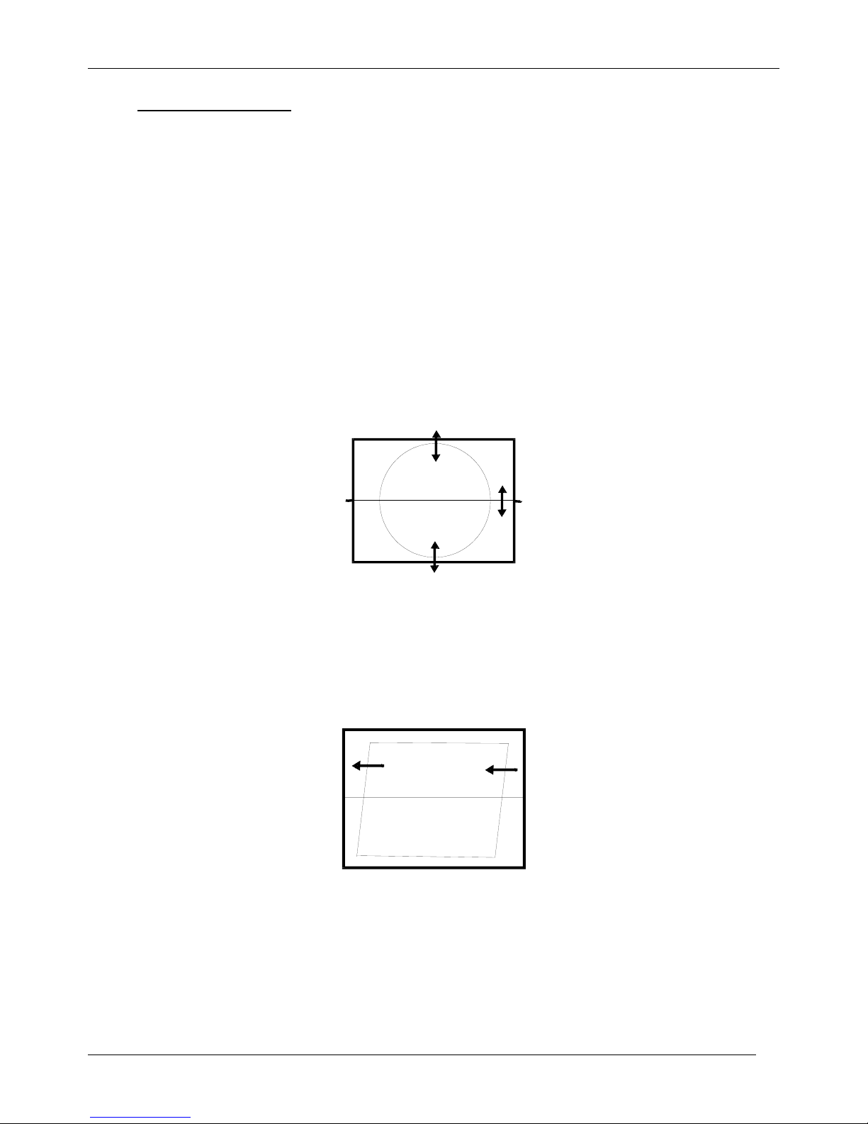
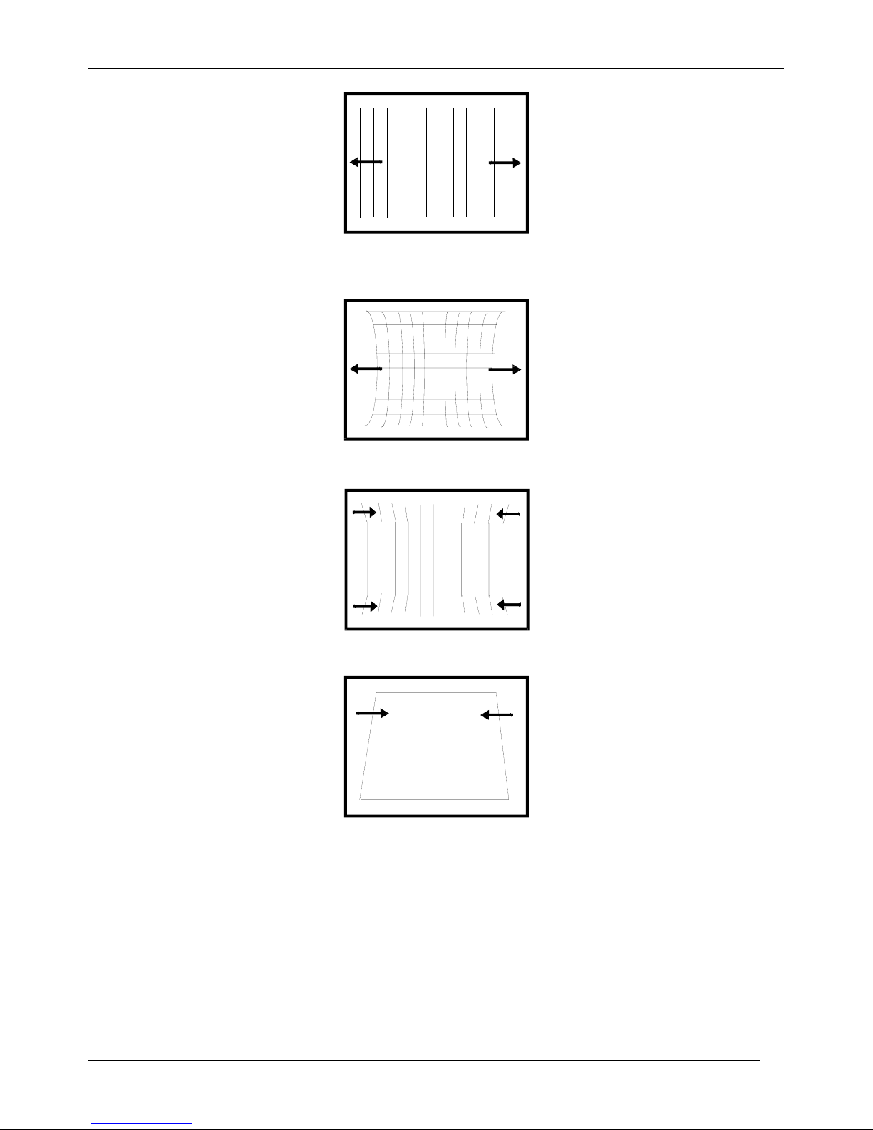
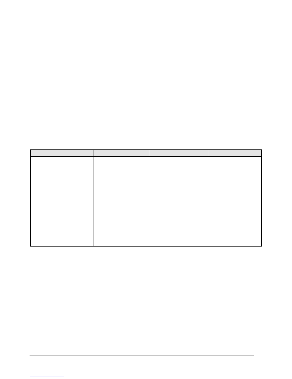
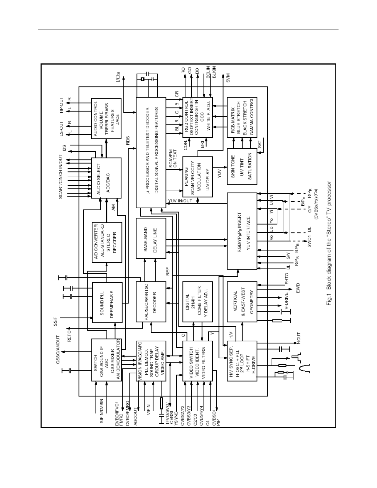
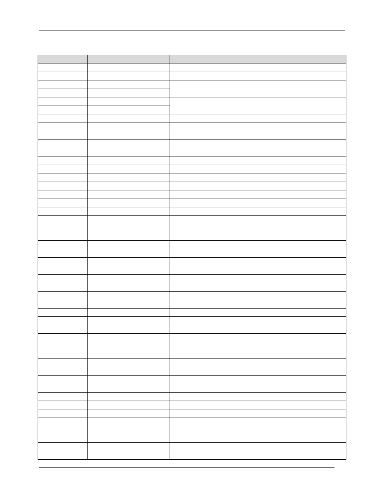
3.7.6 EAST / WEST CORRECTION
Adjust the PARABOLA, HOR WIDTH, CORNER, HOR PARAL, EW TRAPEZ, to compensate for
geometrical distortion.
HOR PARAL
CP-650 Service Manual
DTV R&D Europe
15
HOR WIDTH
adjust for 93% overscan.
PARABOLA
CORNER B & CORNER T
EW TRAPEZ
3.7.7 AGC
- Make sure option bits are correct for the tuner fitted on the chassis (See above how to change
option bits).
- Adjust the antenna signal level at 62 dBµV
- Tune a colour bar pattern.
- Find the “AGC” item in service mode.
- Press the key “OK” on the remote keypad and wait until AGC level stabilise to the optimum
value.
- Alternatively, use “Vol Up/Dwn” keys to adjust manually to the desired Tuner Take Over Point
(TOP).
CP-650 Service Manual
DTV R&D Europe
16
4 IC DESCRIPTION
4.1 UOC
III
Series
The UOC
III
series combines the functions of a Video Signal Processor (VSP) together with a
FLASH embedded TEXT/Control/Graphics µ-Controller (TCG µ-Controller) and US Closed
Caption decoder. In addition the following functions can be added:
• Adaptive digital (4H/2H) PAL/NTSC combfilter
• Teletext decoder with 10 page text memory
• Multi-standard stereo decoder
• BTSC stereo decoder
• Digital sound processing circuit
• Digital video processing circuit
4.1.1 IC MARKING AND VERSION
Chassis IC marking OSD languages ATSS countries Text
CP-650
TDA12021H
1/N1F01
BULGARIAN,
CZECH, GERMAN,
DANISH, SPANISH,
FRENCH, FINNISH,
ENGLISH, GREEK,
HUNGARIAN,
ITALIAN,
NORWEGIAN,
DUTCH,
PORTUGAL,
POLISH,
ROMANIAN,
RUSSIAN,
SWEDISH
Austria, Belgium,
Switzerland, Czech
Republic, Germany,
Denmark, Spain,
France, Finland, GB,
Greece, Hungary, Italy,
Ireland, Norway,
Netherlands, Portugal,
Poland, Sweden,
Slovak Republic,
Others
PAN-EUROPEAN
LATIN, CYRILLIC,
GREEK.
CP-650 Service Manual
DTV R&D Europe
17
4.1.2. BLOCK DIAGRAM
CP-650 Service Manual
DTV R&D Europe
18
4.1.3. PINNING
QFP 128pin Symbol Short Description
1 P1.5/TX Port 1.5 or UART bus
2 P1.4/RX port 1.4 or UART bus
3 P1.2/INT2 port 1.2 or external interrupt 2
4 VSSC3 Ground
5 VDDC3 digital supply to core (1.8V)
6 P2.5/PWM4 port 2.5 or PWM4 output
7 P2.4/PWM3 port 2.4 or PWM3 output
8 VSSC/P digital ground for m-Controller core and periphery
9 P3.3/ADC3 port 3.3 or ADC3 input
10 P3.2/ADC2 port 3.2 or ADC2 input
11 DECV1V8 decoupling 1.8 V supply
12 VDDC1 digital supply to core (+1.8 V)
13 P3.1/ADC1 port 3.1 or ADC1 input
14 P3.0/ADC0 port 3.0 or ADC0 input
15 P2.3/PWM2 port 2.3 or PWM2 output
16 P2.2/PWM1 port 2.2 or PWM1 output
17 P2.1/PWM0 port 2.1 or PWM0 output
18 P2.0/TPWM port 2.0 or Tuning PWM output
19 VDDP(3.3V)
supply to periphery and on-chip voltage regulator (3.3
V)
20 P1.7/SDA port 1.7 or I2C-bus data line
21 P1.6/SCL port 1.6 or I2C-bus clock line
22 P1.3/T1 port 1.3 or Counter/Timer 1 input
23 P0.0/I2SDI1/O port 0.0 or I2S digital input 1 or I2S digital output
24 P0.1/I2SDO1 port 0.1 or I2S digital output 1
25 P0.2/I2SDO2 port 0.2 or I2S digital output 2
26 P0.3/I2SCLK port 0.3 or I2S clock
27 P0.4/I2SWS port 0.4 or I2S word select
28 VSSC2 Ground
29 VDDC2 digital supply to core (1.8 V)
30 P1.1/T0 port 1.1 or Counter/Timer 0 input
31 P1.0/INT1 port 1.0 or external interrupt 1
32 INT0/P0.5
external interrupt 0 or port 0.5 (4 mA current sinking
capability for direct drive of LEDs)
33 VDDadc(1.8) supply voltage video ADC
34 VSSadc ground for on-chip temperature sensor
35 VDDA2(3.3) supply voltage SDAC (3.3 V)
36 VDDA(1.8) analogue supply for audio ADCs (1.8 V)
37 GNDA Ground
38 VREFAD reference voltage for audio ADCs (3.3/2 V)
39 VREFAD_POS positive reference voltage (3.3 V)
40 VREFAD_NEG negative reference voltage (0 V)
41 VDDA1
analog supply for TCG m-Controller and digital supply
for
TV-processor (+3.3 V)
42 BO Blue output
43 GO Green output
CP-650 Service Manual
DTV R&D Europe
19
44 RO Red output
45 BLKIN black current input
46 BCLIN beam current limiter input
47 VP3 3rd supply for TV processor
48 GND3 ground 3 for TV-processor
49 B/PBIN3 3rd B input / PB input
50 G/YIN3 3rd G input / Y input
51 R/PRIN3 3rd R input / PR input
52 INSSW3 3rd RGB / YPBPR insertion input
53 VOUT(SWO1)
V-output for YUV interface (general purpose switch
output)
54 UOUT(INSSW2)
U-output for YUV interface (2nd RGB / YPBPR
insertion input)
55 YOUT Y-output (for YUV interface)
56 YSYNC Y-input for sync separator
57 YIN (G/YIN2/CVBS-Yx)
Y-input for YUV interface (2nd G input / Y input or
CVBS/YX input))
58 UIN (B/PBIN2) U-input for YUV interface (2nd B input / PB input)
59 VIN (R/PRIN2/CX)
V-input for YUV interface (2nd R input / PR input or CX
input)
60 VDDcomb supply voltage for comb filter (5 V)
61 VSScomb ground connection for comb filter
62 HOUT horizontal output
63 FBISO/CSY
flyback input/sandcastle output or composite H/V
timing output
64 SVM scan velocity modulation output
65 CVBSO/PIP CVBS / PIP output
66 AUDOUTHPR audio output for headphone channel (right signal)
67 AUDOUTHPL audio output for headphone channel (left signal)
68 AUDOUTLSR audio output for audio power amplifier (right signal)
69 AUDOUTLSL audio output for audio power amplifier (left signal)
70 C2/C3 chroma-2/3 input
71 CVBS3/Y3 CVBS3/Y3 input
72 AUDIOIN3R audio 3 input (right signal)
73 AUDIOIN3L audio 3 input (left signal)
74 CVBS2/Y2 CVBS2/Y2 input
75 AUDIOIN2R audio 2 input (right signal)
76 AUDIOIN2L audio 2 input (left signal)
77 C4 chroma-4 input
78 CVBS4/Y4 CVBS4/Y4 input
79 AUDIOIN4R audio-4 input (right signal)
80 AUDIOIN4L audio-4 input (left signal)
81 IFVO/SVO/CVBSI (2) IF video output / selected CVBS output / CVBS input
82 VP2 2nd supply voltage TV processor (+5 V)
83 AGC2SIF AGC capacitor second sound IF
84 VCC8V 8 Volt supply for audio switches
85 DVBO/FMRO (2) Digital Video Broadcast output / FM radio output
86 DVBO/IFVO/FMRO (2)
Digital Video Broadcast output / IF video output / FM
radio output

CP-650 Service Manual
DTV R&D Europe
20
87 SIFAGC/DVBAGC (2)
AGC sound IF / internal-external AGC for DVB
applications
88 PLLIF IF-PLL loop filter
89 GND2 ground 2 for TV processor
90
QSSO/AMOUT/AUDEE
M (2)
QSS intercarrier output / AM output / deemphasis
(front-end audio
out)
91 DECSDEM decoupling sound demodulator
92 AUDOUTSR audio output for SCART/CINCH (right signal)
93 AUDOUTSL audio output for SCART/CINCH (left signal)
94 AUDIOIN5R audio-5 input (right signal)
95 AUDIOIN5L audio-5 input (left signal)
96
AVL/SWO/SSIF/
REFO/REFIN (2)
Automatic Volume Levelling / switch output / sound IF
input /
subcarrier reference output / external reference signal
input for I
signal mixer for DVB operation
97 EHTO EHT/overvoltage protection input
98 AGCOUT tuner AGC output
99 SIFIN2/DVBIN2 (2) SIF input 2 / DVB input 2
100 SIFIN1/DVBIN1 (2) SIF input 1 / DVB input 1
101 GNDIF ground connection for IF amplifier
102 IREF reference current input
103 VSC vertical sawtooth capacitor
104 VIFIN2 IF input 2
105 VIFIN1 IF input 1
106 VDRA vertical drive A output
107 VDRB vertical drive B output
108 EWD/AVL (1) East-West drive output or AVL capacitor
109 DECBG bandgap decoupling
110 SECPLL SECAM PLL decoupling
111 GND1 ground 1 for TV-processor
112 PH1LF phase-1 filter
113 PH2LF phase-2 filter
114 VP1 1st supply voltage TV-processor (+5 V)
115 DECDIG decoupling digital supply
116 VGUARD/SWIO
V-guard input / I/O switch (e.g. 4 mA current sinking
capability for
direct drive of LEDs)
117 VSSA1 Ground
118 XTALOUT crystal oscillator output
119 XTALIN crystal oscillator input
120 VREF_POS_HPR positive reference voltage SDAC (3.3 V)
121 VREF_NEG_HPL+HPR negative reference voltage SDAC (0 V)
122 VREF_POS_LSR+HPR positive reference voltage SDAC (3.3 V)
123 VREF_NEG_LSL+HPL negative reference voltage SDAC (0 V)
124 VREF_POS_LSL positive reference voltage SDAC (3.3 V)
125 VDDA3(3.3V) supply (3.3 V)
126 VDDC4 digital supply to SDACs (1.8V)
127 VSSC4 Ground
128 VSSP2 Ground

CP-650 Service Manual
DTV R&D Europe
21
4.1.4 FEATURES
Analogue Video Processing (all versions)
· Multi-standard vision IF circuit with alignment-free PLL demodulator
· Internal (switchable) time-constant for the IF-AGC circuit
· Switchable group delay correction and sound trap (with switchable centre frequency) for the
demodulated CVBS signal
· DVB/VSB IF circuit for preprocessing of digital TV signals.
· Video switch with 3 external CVBS inputs and a CVBS output. All CVBS inputs can be used as
Y-input for Y/C signals. However, only 2 Y/C sources can be selected because the circuit has 2
chroma inputs. It is possible to add an additional CVBS(Y)/C input (CVBS/YX and CX) when the
YUV interface and the RGB/YPRPB input are not needed.
· Automatic Y/C signal detector
· Adaptive digital (4H/2H) PAL/NTSC comb filter for optimum separation of the luminance and the
chrominance signal.
· Integrated luminance delay line with adjustable delay time
· Picture improvement features with peaking (with switchable centre frequency, depeaking,
variable positive/negative peak ratio, variable pre-/overshoot ratio and video dependent coring),
dynamic skin tone control, gamma control and blue- and black stretching. All features are
available for CVBS, Y/C and RGB/YPBPR signals.
· Switchable DC transfer ratio for the luminance signal
· Only one reference (24.576 MHz) crystal required for the TCG m-Controller, digital sound
processor, Teletext and the colour decoder
· Multi-standard colour decoder with automatic search system and various “forced mode”
possibilities
· Internal base-band delay line
· Indication of the Signal-to-Noise ratio of the incoming CVBS signal
· Linear RGB/YPBPR input with fast insertion.
· YUV interface. When this feature is not required some pins can be used as additional
RGB/YPBPR input. It is also possible to use these pins for additional CVBS (or Y/C) input
(CVBS/YX and CX).
· Tint control for external RGB/YPBPR signals
· Scan Velocity Modulation output. The SVM circuit is active for all the incoming CVBS, Y/C and
RGB/YPBPR signals. The SVM function can also be used during the display of teletext pages.
· RGB control circuit with ‘Continuous Cathode Calibration’, white point and black level off-set
adjustment so that the colour temperature of the dark and the light parts of the screen can be
chosen independently.
· Contrast reduction possibility during mixed-mode of OSD and Text signals
· Adjustable ‘wide blanking’ of the RGB outputs
· Horizontal synchronization with two control loops and alignment-free horizontal oscillator
· Vertical count-down circuit
· Vertical driver optimized for DC-coupled vertical output stages
· Horizontal and vertical geometry processing with horizontal parallelogram and bow correction
and horizontal and vertical zoom
· Low-power start-up of the horizontal drive circuit
Analogue video processing (stereo versions)
· The low-pass filtered ‘mixed down’ I signal is available via a single ended or balanced output
stage.
Analogue video processing (mono versions)
· The low-pass filtered ‘mixed down’ I signal is available via a single ended output stage
Digital Video Processing (some versions)
· Double Window mode applications. It is possible to display a video and a text window or 2 text

CP-650 Service Manual
DTV R&D Europe
22
windows in parallel.
· Linear and non-linear horizontal scaling of the video signal to be displayed.
Sound Demodulation (all versions)
· Separate SIF (Sound IF) input for single reference QSS (Quasi Split Sound) demodulation.
· AM demodulator without extra reference circuit
· The mono intercarrier sound circuit has a selective FM-PLL demodulator which can be switched
to the different FM sound frequencies (4.5/5.5/6.0/6.5 MHz). The quality of this system is such
that the external band-pass filters can be omitted. In the stereo versions of UOCIII the use of this
demodulator is optional for special applications. Normally the FM demodulators of the stereo
demodulator/decoder part are used (see below).
· The FM-PLL demodulator can be set to centre frequencies of 4.72/5.74 MHz so that a second
sound channel can be demodulated. In such an application it is necessary that an external
bandpass filter is inserted.
· The vision IF and mono intercarrier sound circuit can be used for the demodulation of FM radio
signals. With an external FM tuner also signals with an IF frequency of 10.7 MHz can be
demodulated.
· Switch to select between 2nd SIF from QSS demodulation or external FM (SSIF)
Audio Interfaces and switching (stereo versions with Audio DSP)
· Audio switch circuit with 4 stereo inputs, a stereo output for SCART/CINCH, 1 stereo output for
HEADPHONE. The headphone channel has an analogue volume control circuit for the L and R
channel. Finally 1 stereo SPEAKER output with digital controls.
· AVL (Automatic Volume Levelling) circuit for the headphone channel.
· Digital input crossbar switch for all digital signal sources and destinations
· Digital output crossbar for exchange of channel processing functionality
· Digital audio input interface (stereo I2S input interface)
· Digital audio output interface (stereo I2S output interface)
Audio interfaces and switching (AV stereo versions without Audio DSP)
· Audio switch circuit with 4 stereo inputs, a stereo output for SCART/CINCH and a stereo
SPEAKER output with analogue volume control.
· Analogue mono AVL circuit at left audio channel
Audio interfaces and switching (mono versions)
· Audio switch circuit with 4 external audio (mono) inputs and a volume controlled output
· AVL circuit
Stereo Demodulator and Decoder (full stereo versions)
· Demodulator and Decoder Easy Programming (DDEP)
· Auto standard detection (ASD)
· Static Standard Selection (SSS)
· DQPSK demodulation for different standards, simultaneously with 1-channel FM demodulation
· NICAM decoding (B/G, I, D/K and L standard)
· Two-carrier multistandard FM demodulation (B/G, D/K and M standard)
· Decoding for three analog multi-channel systems (A2, A2+ and A2*) and satellite sound
· Adaptive de-emphasis for satellite FM
· Optional AM demodulation for system L, simultaneously with NICAM
· Identification A2 systems (B/G, D/K and M standard) with different identification time constants
· FM pilot carrier present detector
· Monitor selection for FM/AM DC values and signals, with peak and quasi peak detection option
· BTSC MPX decoder
· SAP decoder
· dbx® noise reduction (4)
· Japan (EIAJ) decoder
· FM radio decoder
· Soft-mute for DEMDEC outputs DEC, MONO and SAP
 Loading...