

Daewoo DTH-28, DTG-28, DTG-29 Setup Manual

HELPLINE NUMBER : 01189 252627
With queries, please quote the page number, reference number and model number
SET-UP MANUAL
Colour Television
DTG-28
DTG-29
DTH-28
DTH-29

1
ADDITIONAL INFORMATION FOR TV’S SOLD IN GREAT BRITAIN
The appliance is supplied with a moulded three pin mains plug fitted with 5Amp fuse.
Should the fuse require replacement, it must be replaced with a fuse rated at 5 amp
and approved by ASTA or BSI to BS1362.
The plug contains a removable fuse cover that must be refitted when the fuse is
replaced.In the event of the fuse cover being lost or damaged, the plug must not be
used until a replacement cover has been obtained.Replacement fuse covers can be
purchased from your nearest electrical dealer and must be the same colour as the
original.
If the moulded mains plug is unsuitable for the socket outlet in your home or is
removed for any other reasons, then the fuse should be removed and the cut off plug
disposed of safely to prevent the hazard of electric shock.
There is a danger of electric shock if the cut off plug is inserted into any socket outlet.
If a replacement plug is to be fitted, please observe the wiring code shown below.The
wires in the mains lead are coloured in the accordance with the following code:
Blue-neutral Brown-live
As the colours of the wires in the mains lead of this appliance may not correspond with
the coloured markings identifying the terminals in your plug, proceed as follows:
The wire which is coloured blue must be connected to the terminal which is marked
with the letter N or coloured black.The wire which is coloured brown must be connected
to the terminal which is marked with the letter L or coloured red.
Do not make any connections to the terminal in the plug which is marked by the letter
E by the safety earth symbol or coloured green or green and yellow.
2
CONTENTS
REMOTE CONTROL & TV CONNECTIONS 3
IMPORTANT SAFEGUARDS 4
INSTALLATION 4
START UP 5
CONNECTING EXTERNAL EQUIPMENT 5
DAILY USE 6
MENUS DESCRIPTION 9
TELETEXT 14
3
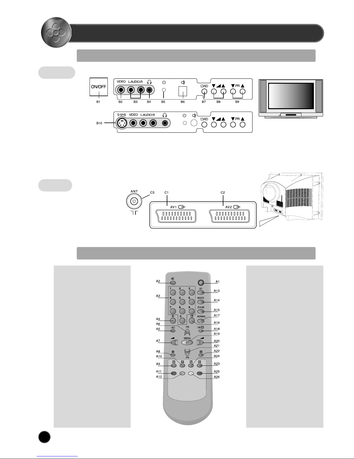
REMOTE CONTROL & TV CONNECTIONS
LOCAL CONTROL
REMOTE CONTROL UNIT
Front
(Option for real flat TVs)
DTG-28/DTG-29
Rear
C1 SCART 1 socket
C2 SCART 2 socket
C3 AERIAL jack
TV mode
POWER
SOUND MUTE
NUMBER 0..9
SLEEP
TV / AV
PROGRAM UP
(CURSOR UP)
VOLUME DOWN
(CURSOR LEFT)
.
.
.
SKIP
MOVE
3D(SOUND EFFECT)
MODE
ZOOM
RECALL
NORMAL
OK/PRESET
MENU
VOLUME UP
(CURSOR RIGHT)
PROGRAM DOWN
(CURSOR DOWN)
TV > TELETEXT
.
.
.
DELETE / FREEZE
TELETEXT mode
POWER
SOUND MUTE
NUMBER 0..9
.
.
PAGE UP
VOL/BRIGHT/CONTRAST DOWN
CANCEL
PAGE HOLD
SUBPAGE
RED
GREEN
.
.
.
.
.
INDEX
VOL/BRIGHT/CONTRAST
MENU SELECTION
VOL/BRIGHT/CONTRAST UP
PAGE DOWN
TELETEXT > TV
HEIGHT
REVEAL
CYAN
YELLOW
A1
A2
A3
A4
A5
A6
A7
A8
A9
A10
A11
A12
A13
A14
A15
A16
A17
A18
A19
A20
A21
A22
A23
A24
A25
A26
A1
A2
A3
A4
A5
A6
A7
A8
A9
A10
A11
A12
A13
A14
A15
A16
A17
A18
A19
A20
A21
A22
A23
A24
A25
A26
B1 MAIN POWER button
B2 FRONT VIDEO INPUT socket
B3 FRONT AUDIO INPUT (L + R) socket
B4 HEADPHONE socket
B5 STAND-BY indicator
B6 REMOTE sensor
B7 TV / AV button
B8 VOLUME UP/DOWN buttons
B9 PROGRAM UP/DOWN buttons
B10 FRONT PANEL S-VIDEO jack
4
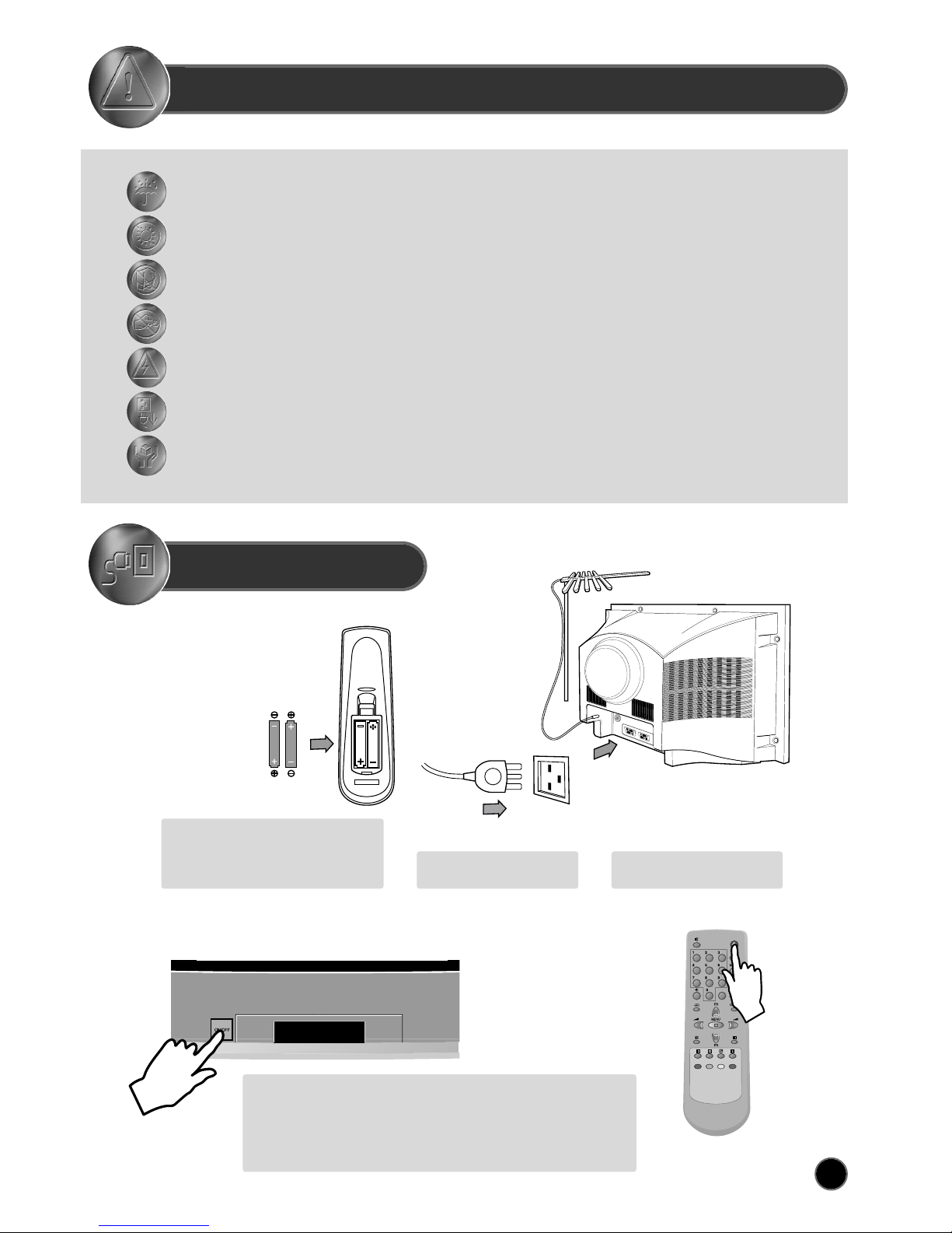
IMPORTANT SAFEGUARDS
INSTALLATION
WATER AND MOISTURE
The apparatus shall not be exposed to dripping or splashing water and no object filled with liquids, such as vases , should be
placed on the apparatus.
HEAT
Never place the set near heat sources.
Never put a naked flame, such as a candle, on the top of TV set.
VENTILATION
Do not cover the ventilation openings in the cabinet and never place the set in a confined space such as in a bookcase
or built-in cabinet unless proper ventilation is provided. Leave a minimum 10 cm gap all around the unit.
OBJECT ENTRY
Do not insert foreign objects, such as needles and coins, in the ventilation openings.
LIGHTNING STRIKE
You should disconnect the set from the mains and the aerial system during thunderstorms.
CLEANING
Unplug the set from the mains while cleaning.
AFTER MOVING THE SET
If the set is moved or turned, the MAIN POWER button must be switched off for at least 15 minutes
in order to take out colour patches on the screen.
Batteries
Open remote control battery compartment
(at the rear) and insert two 1.5V type AAA
batteries. Warning: be careful to respect
battery polarities.
Power on the TV set using front panel MAIN POWER button (B1).
Select your preferred language from the LANGUAGE menu (see
section START UP on page 5).
Press the remote control MENU button (A19) to enter the main menu.
Select Install menu to tune and memorise TV programs.
Insert the main plug into a
230V 50Hz AC power socket.
Connect aerial to aerial jack (C3).
SWITCHING ON AND OFF
5
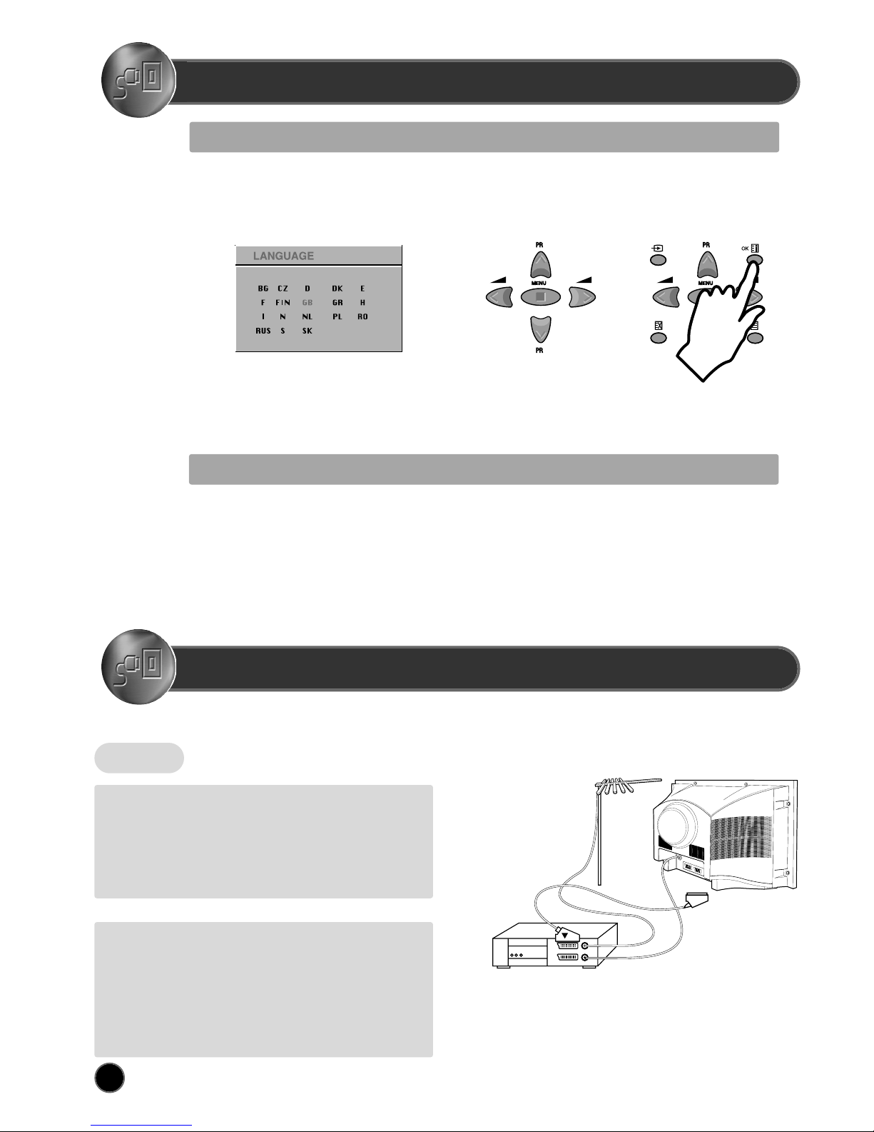
START UP
LANGUAGE MENU
The very first time that you turn on the TV, the LANGUAGE menu will appear on the screen. Its purpose is to enable you to select the language that will be used
for all the OSD (On Screen Display) menus. The user must enter a choice of language before proceeding further.
The language entered at this stage can still be modified at any later time, by entering the LANGUAGE menu (accessed from the FEATURES menu: see later
section under MENU DESCRIPTION).
The descriptions used in the menu are those of the country code (e.g. GB = English, NL = Holland etc).
The rear Scart1 (C1), Scart2 (C2) sockets, the front AV socket (B2) (B3), and the S-VHS socket (B10,
option: real flat TVs) are three dedicated sockets to connect audio-video equipment.
Selection is made by use of the remote control CURSOR UP (A6) / CURSOR DOWN (A21) keys and CURSOR RIGHT
(A20) / LEFT (A7) keys.
Once you are satisfied with your selection, push the OK button (A18) to confirm your choice. The choice will briefly
highlight in red, after which the menu will disappear.
Note : The languages shown are subject to modification without prior notice.
Rear
REAR SCART 1 SOCKET (AV1)
This socket (C1) has video / audio inputs and outputs. It is recommended to
connect to this socket automatic AV switching equipment such as pay-TV
decoders, video games, DVD players and most VCR’s.
In most cases, when connecting powered equipment to this socket, the TV
set switches automatically to AV mode. If not, then use the TV/AV buttons
(A5) or (B7) to select AV1.
REAR SCART 2 SOCKET (AV2)
This socket (C2) has video / audio inputs and outputs. Automatic AV
switching equipment(for example most VCR’s) can be connected to this
socket.
In most cases, when connecting powered equipment to this socket, the TV
set switches automatically to AV mode. If not, then use the TV/AV buttons
(A5) or (B7) to select AV2.
You can also receive an S-VHS signal with REAR SCART2 socket, by
selecting SVHS2 with the TV / AV buttons (A5) or (B7).
VCR / DVD / Video Game / Pay-TV decoder Important:
If your video equipment does not have SCART socket(s), or
if you wish to use only the aerial (RF) connection (not
recommended), then you should make use of PR 00 on the
TV set for best performance.
CONNECTING EXTERNAL EQUIPMENT
AUTOMATIC TUNING
Automatic Tuning System
If you have a satellite decoder: If your decoder is connected to the TV set by the aerial jack (C3), you must power on the demodulator and tune
Sky News before starting ATSS .
ATSS = Automatic Tuning and Sorting System. To start the ATSS function:
- Select "ATSS " function.
- Adjust to the required country.
- Press and hold the OK button (A18) to start the automatic tuning.
The ATSS function has started when the phrase "Please Wait !" appears (in red characters ) in the help instructions box, below the Install menu.
When the ATSS function is finished, the stored programs are displayed on screen using Edit menu presentation (to Exit tuning before automatic
tuning is finished, press the remote control MENU button (A19) ).
 Loading...