

Page 1

S/M No. : TCM220NEF0
Service Manual
Colour Television
CHASSIS : CM-220N
Model : DTH-20D5FSN
DTH-21D4FSN
DTH-20D5FSN DTH-21D4FSN
SPECIFICATIONS
MODEL
ITEM
TV STANDARD PAL-M/N
POWER INPUT 220V 50/60HZ
POWER CONSUMPTION 88W
TUNING SYSTEM Frequency Synthesizer (FS) Tuning System
TV VHF(L) : CH2 ~ CH6
CATV VHF(L) : 5A,A,B,A-5-A-1
TUNING RANGES CH2-CH6
SOUND OUTPUT 5W + 5W
SPEAKER 8 ohm 5W X 2EA
ANTENNA INPUT IMPEDANCE 75 ohm Unbalanced
AUXILIARY INPUT TERMINAL
INTERMEDIATE FREQUENCIES Sound IF Carrier Frequency : 41.25 MHZ
REMOTE CONTROL R-43A01
SPECIAL FUNCTIONS
Font : Video, Audio, Earphone
Rear:Video, Audio,(R,L)
Picture IF Carrier Frequency : 45.75 MHZ
Color Sub-Carrer Frequency : 3.579545 MHZ
1) ICON MENU TYPE
2) 3-Language OSD
3) WITH CAPTION
4) CH LABEL
DTH-20D5FSN
UHF(H) : CH7 ~ CH13
UHF : CH14 ~ CH69
VHF(H) : C-W+11
CH7-CH13
UHF : W+12-W+84
DTH-21D4FSN
DAEWOO ELECTRONICS CO., LTD
http : //svc.dwe.co.kr May.2001
Page 2

TABLE OF CONTENTS
SPECIFICATIONS..................................................................................................................................... 2
CIRCUIT BLOCK KIAGRAM .................................................................................................................... 3
ALIGNMENT INSTRUCTION.................................................................................................................... 4
Y our Remote Control ..........................................................................................................................................4
Service Mode Adjustment...................................................................................................................................5
Assembly Adjustment .........................................................................................................................................6
SCHEMA TIC DIAGRAM ........................................................................................................................... 10
PRINTED CIRCUIT BOARD ..................................................................................................................... 11
EXPLODED VIEW..................................................................................................................................... 12
SERVICE P ARTS LIST ............................................................................................................................. 14
APPENDIX (“Appendix is provided only by internet [http://svc.dwe.co.kr]”)
TROUBLE SHOOTING GUIDE................................................................................................................. 34
1
. No Power......................................................................................................................................................34
2. No Picture .....................................................................................................................................................35
3. No Sound......................................................................................................................................................36
4. CH Don’t Stop...............................................................................................................................................37
5. No Color........................................................................................................................................................38
6. No Vertical Deflection....................................................................................................................................38
7. No On-Screen Display ..................................................................................................................................39
8. Remote ControlDoes Not Operate................................................................................................................39
1
Page 3
SPECIFICATIONS
CAUTION
CM-220N
MODEL
ITEM
TV STAND ARD PAL-M/N
POWER INPUT 220V 50/60HZ
POWER CONSUMPTION 88W
TUNING SYSTEM Frequency Synthesizer (FS) Tuning System
TV VHF(L) : CH2 ~ CH6
CATV VHF(L) : 5A,A,B,A-5-A-1
TUNING RANGES CH2-CH6
SOUND OUTPUT 5W + 5W
SPEAKER 8 ohm 5W X 2EA
ANTENNA INPUT IMPEDANCE 75 ohm Unbalanced
A UXILIAR Y INPUT TERMINAL
INTERMEDIATE FREQ UENCIES Sound IF Carrier Frequency : 41.25 MHZ
REMOTE CONTROL R-43A01
SPECIAL FUNCTIONS
Font : Video, Audio, Earphone
Rear:Video, Audio ,(R,L)
Picture IF Carrier Frequency : 45.75 MHZ
Color Sub-Carrer Frequency : 3.579545 MHZ
1) ICON MENU TYPE
2) 3-Language OSD
3) WITH CAPTION
4) CH LABEL
DTH-20D5FSN
UHF(H) : CH7 ~ CH13
UHF : CH14 ~ CH69
VHF(H) : C-W+11
CH7-CH13
UHF : W+12-W+84
DTH-21D4FSN
2
Page 4
CIRCUIT BLOCK DIAGRAM
3
Page 5
ALIGNMENT INSTRUCTION
CAUTION
Your Remote Control
1. POWER
Use this button to turn your TV on or off .
2. MUTE
Use to turn the TV’s sound on and off.
3. CH
Use these buttons to change your TV’ s v olume , to
activate selections in the menu system.
4. VOL
Use these buttons to change your TV’ s v olume , to
activate selections in the meny system,or to change
audio and video settings.
5. MENU
Use this button to turn the TV’s menu system on and off .
6. DISPLAY
Use this button to display the channel numbeer and
status.
7. INPUT
Use this button to select the TV’s signal source.
8. VIDEO
Use this button to display video adjustment.
9. 0-9
Use these buttons to change channels.
10. SLEEP
Use this button to program the TV to turn off after a
certain time.
11. PREVIOUS
Use this button to return to the previous channel yo u
were watching.
4
Page 6
ALIGNMENT INSTRUCTIONS
SERVICE MODE ADJUSTMENTS
Follow the steps belo w whene v er service adjustment is required. See Table- A and Table- B to determine if
service adjustments are required.
1) How to enter the service mode using the user remote control.
• Turn the set on.
• Direct the remote control to the reception window of T V.
• Push buttons of remote control in sequence as follo ws.
1 MUTE DISPLAY MUTE
• Then, the screen will appear as f ollo ws.
• Using the channel up or channel down button, select the item you wish to adjust.
(The color of selected item turns into the red.)
• Press the volume up or down b utton to enter in the service mode you wish to adjust.
2) How to memorize the adjusted values in the service mode.
• Must press DISPL AY button the state which the screen is displaying each of service menus
after all adjustments are completed each of all service menu.
Ta ble-A : Adjust the values of service mode when a part is replaced.
PART
REPLACED
I701 Data is stored in I703
(U-COM)
I101
(MAIN)
I703
(EEPROM)
NECESSARY UNNECESSARY
ADJUSTMENT
NOTES
Initial setting values are written from I701.
Adjusting ltems
S5 RF AGCD
S6 H.PHASE/V.POSI/V.SIZE
S8 RD/BD/RB/GB/BB
S9 Subbrightness
CR T Adjust items related to picture tube only. (White Balance adjustment)
5
Page 7
ALIGNMENT INSTRUCTIONS
Table-B
MODE ADJUSTMENT ITEMS REMARKS
S2 Screen Adjustment - -
Auto RF A GC - Video Le vel (VIDEOL) 7 0~7 Must be set to 7
RF AGC Delay (RFA GCD)
S5
FM Lev el (FM.LEV) 8 0~31 Must be set to 20
AGC P oint 3.75 - Select A GC reference v oltage
A/D V ALUE - Horizontal Phase(H.PHASE)
Vertical Position (V.POSI)
Vertical Size (V.SIZE)
S6
NO SD POWER OFF YES - Automatically turn off in 15min for no received signal.
V ertical S-Correction (V SC) 0 0~31 Must be set to 6
V ertical Linearity (V LIN) 20 0~31 Must be set to 16
Internal Black - - Display internal BLACK pattern
Internal 100% White - - Displa y internal 100% WHITE
S7
Internal 60% White - - Displa y internal 60% WHITE
Internal Cross Pattern - - Displa y internal CROSS pattern
Red Drive (RD)
Green Drive (GD) 10 0~15 Must be set to 10
Blue Drive (BD)
S8
Red Bias (RB)
Green Bias (GB)
Blue Bias (BB)
Subbrightness
Contrast 10 0~27
S9
Tint 27 0~27
Color 15 0~27
S12 Forw arding Mode - F actory Initialization
DATA
INITIAL RANGE
*
*
*
*
*
*
*
*
*
*
0~63 Align RF AGC threshold
0~31 Align sync to flyback pulse, using internal cross pattern(S7)
0~63 Align vertical DC bias, using internal cross pattern(S7)
0~127 Align vertical amplitude, using internal cross pattern(S7)
0~127 Align RED OUT Ievel
0~127 Align BLUE OUT AC level
0~255 Align RED OUT DC Ievel
0~255 Align GREEN OUT DC Ievel
0~255 Align BLUE OUT DC Ievel
0~127 Align common RGB DC level
* indicates the items with different settings each of sets
ASSEMBLY ADJUSTMENTS
1) SCREEN ADJUSTMENT (S2)
Enter the service mode and select service adjustment S2.
You cna see the one horizontal line on the screen.
Adjust the Screen Control Volume (located on FBT) so that the horizontal line onscreen may be
disappeared.
Press the volume up or down b utton to e xit in the screen adjustment mode.
NOTE
IN THE SCREEN ADJUSTMENT MODE, DONT PRESS OTHER BUTTONS EXCEPT V OLUME UP OR DOWN BUTTON.
6
Page 8
ALIGNMENT INSTRUCTIONS
2) FOCUS ADJUSTMENT
• Turn in a local station and adjust the Focus Control knob (located on FBT) f or best picture
details at high light condition.
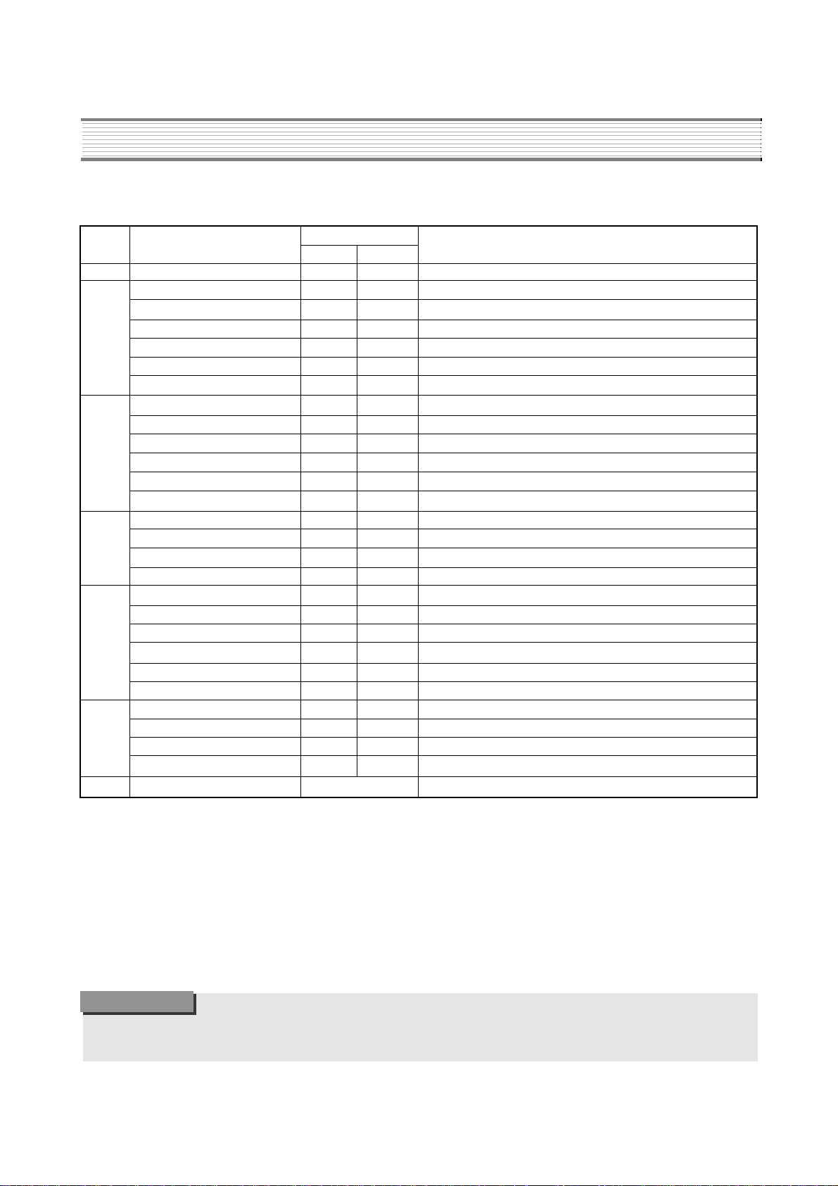
3) RF AGC DELAY ADJUSTMENT (S5)
• Receive a good local channel.
• Enter the service mode and select service adjustment S5.
• You can see the OSD as shown in below.
• Select RFAGCD item, press the volume up or down button until noise or beat in picture disappears.
• Press the DISPLAY b utton to memorize the data.
4) GEOMETRIC ADJUSTMENTS (S6)
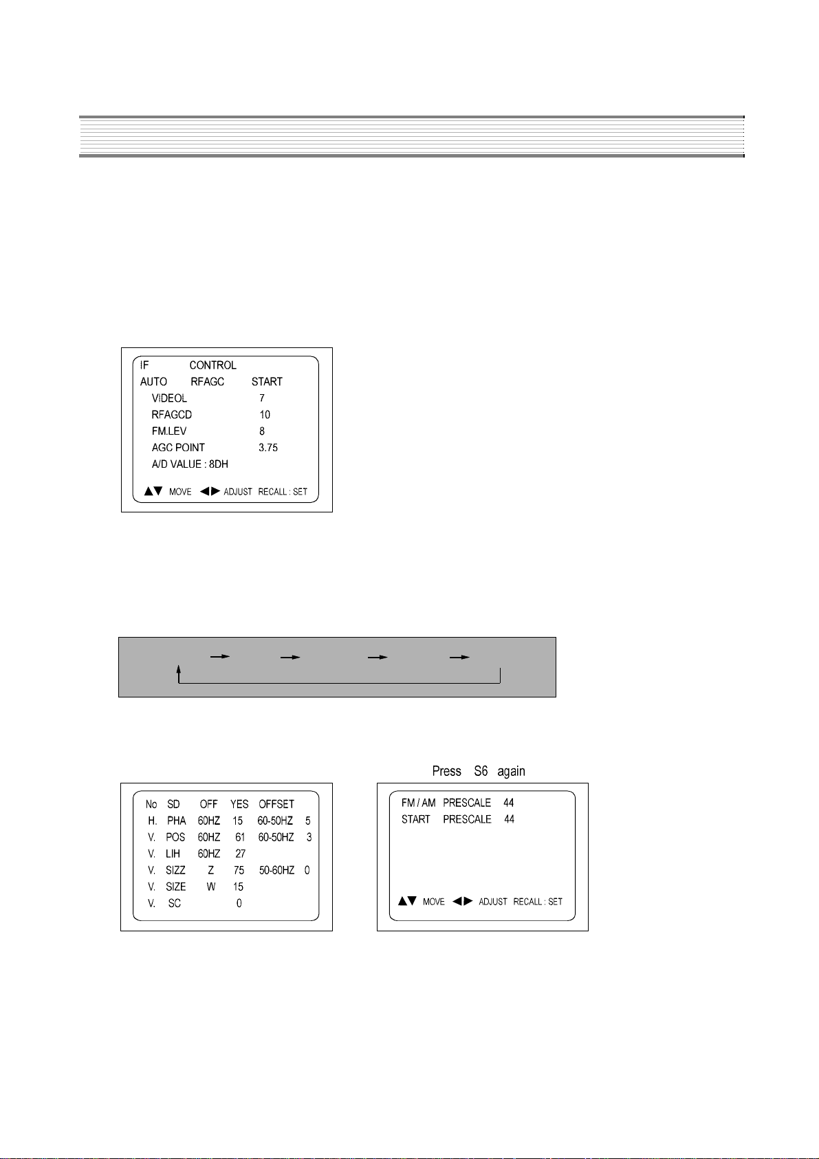
• Enter the service mode and select service adjustment S7.
• Whene v er y ou select the “S7” using the v olume up or do wn button, the screen is changing lik e this.
NORMAL BLACK WHITE100 WHITE60 CROSS
• Using the volume up or down b utton, select internal cross pattern.
• Select service adjustment S6.
• You can see the OSD as shown in below.
4-1. Horizontal P osition Adjustment
• Select H.PHASE item, adjust H.PHASE data value to obtain proper horizontal centering of the
internal cross pattern at the left and right of the screen.
4-2. Vertical P osition Adjustment
• Select V.POSI item, adjust V.POSI data value to center the raster properly on the screen.
7
Page 9
ALIGNMENT INSTRUCTIONS
4-3. Vertical Size Adjustment
Select “V.SIZE” item, adjust “V.SIZE” data value to proper vertical size as follows.
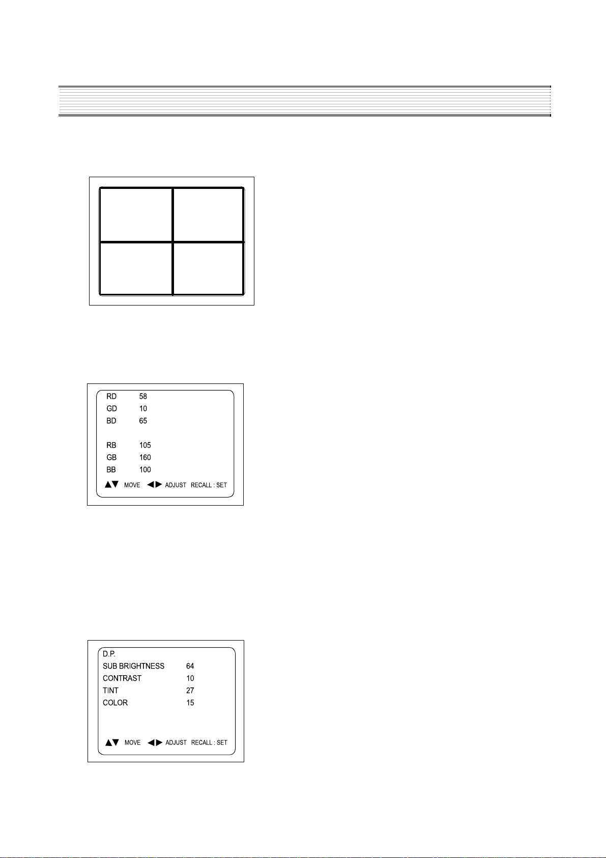
5) WHITE BALANCE ADJUSTMENT (S8)
Receive a good local channel.
Enter the service mode and select service adjustment S8.
You can see the OSD as shown in below .
Using volume up or v olume down, adjust service adjustment data of RD/GD/BD and RB/GB/BB until a good gra y
scale with normal whites is obtained. ALIGNMENT INSTR UCTIONS
Press the DISPLAY button to memorize the data.
6) DIGITAL PRESET(D.P) ADJUSTMENTS (S9)
SUBBRIGHTNESS ADJUSTMENT
Receive a good local channel.
Enter the service mode and select service adjustment S9.
You can see the OSD as shoown in below .
8
Page 10

ALIGNMENT INSTRUCTIONS
Select Subbrightness item, adjust Subbrightness data value to obtain normal brightness level.
Press the DISPLAY button to memorize the data.
CONTRAST
Fixed value = 10
TINT
Fixed value = 27
COLOR
Fixed value = 15
7) FACTORY OUTGOING MODE (S12 : FACT)
If you select the S12, then the set becomes factory outgoing status.
You can see the OSD “outgoing OK”
9
Page 11
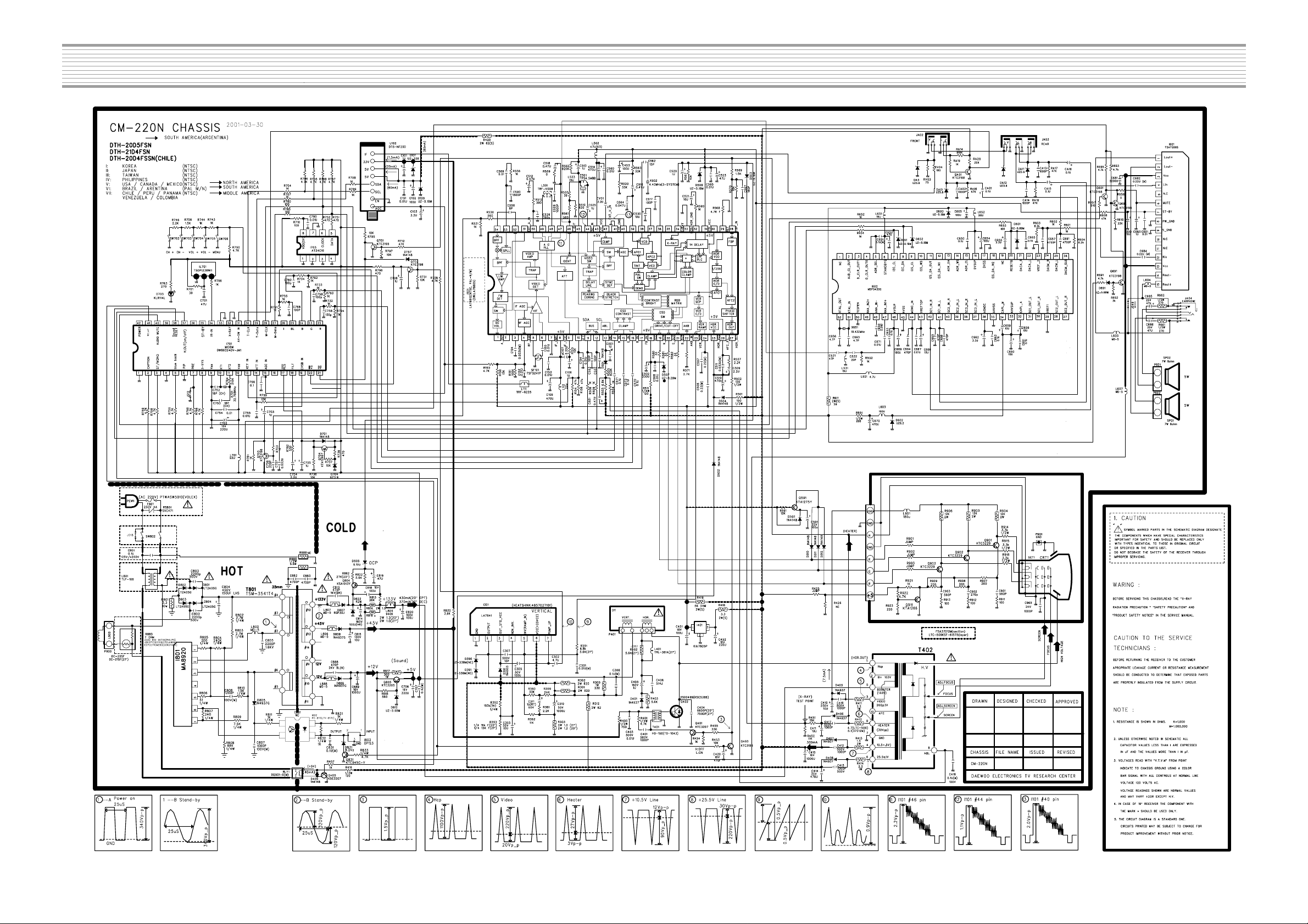
SCHEMATIC DIAGRAM
- 10 -
Page 12
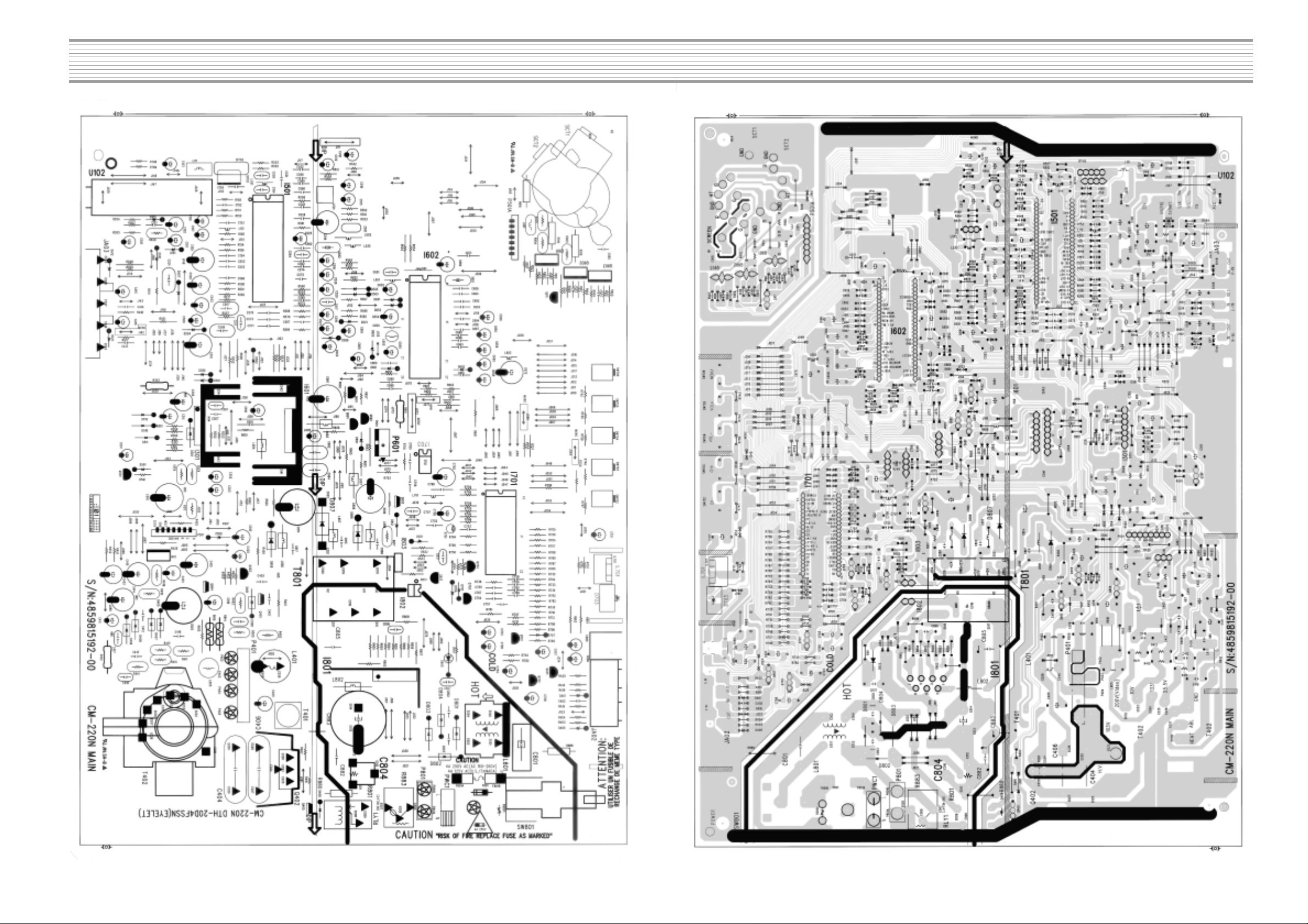
PRINTED CIRCUIT BOARD
PCB MAIN
- 11 -
Page 13
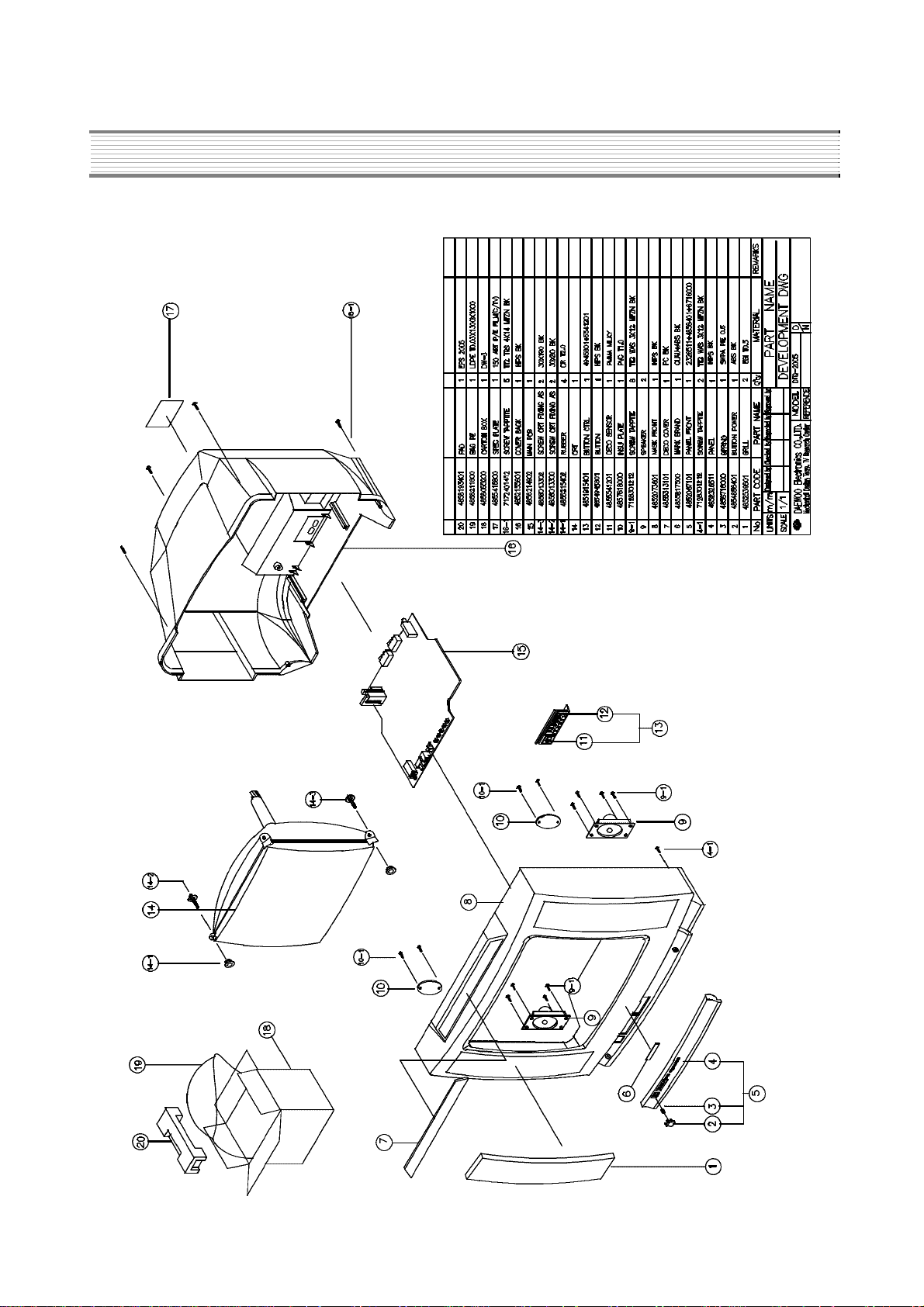
EXPLODED VIEW
DTH-20D5FSN
12
Page 14

EXPLODED VIEW
DTH-21D4FSN
13
Page 15

✐ CAUTION : In this Service Manual, some parts can be changed for improving their
performance without notice in the parts list. So, if you need the latest parts
information, please refer to PPL(Parts Price List)in Service information
Center(http://svc.dwe.co.kr)
SERVICE PARTS LIST
LOC PART CODE PART NAME PART DESCRIPTION REMARK
ZZ100 48B4343A01 TRANSMITTER REMOCON R-43A01 (AA) ®
ZZ110 PTACPWD362 A CCESSORY AS DTH-20D5FS
10 4850A02510 ANT ROD S3BW216B (L=600 MM)
30 4850Q00810 BATTERY R6P/LN
40 4850A02050 TRANS ANT MATCHING UMT P A 002
M821 4858213800 BAG INSTRUCTION L.D.P.E T0.05X250X400
ZZ120 PTBCSHD362 CO VER BA CK AS DTH-20D5FS
M211 4852155601 COVER BACK HIPS BK
M781 4857817611 CLOTH BLA CK FEL T 200X20X0.7
M782 4857817610 CLOTH BLA CK FEL T 300X20X0.7
ZZ130 PTPKCPD362 PACKING AS DTH-20D5FS
M801 4858055200 BOX CART ON DW -3
M811 4858193401 PAD EPS 20D5
M821 4858211800 BAG P.E L.D.P.E T0.03X1300X1000
ZZ131 48519A5110 CRT GR OUND NET 2001S-1015-1P
ZZ132 58G0000146 COIL DEGAUSSING DC-20SF
ZZ140 PTCACAD441 CABINET AS DTH-20D5FSN
CRT1 4859631667 CRT A48JLL91X50(P) M16 ®
CRT1A 4856215402 W ASHER RUBBER CR T2.0
CRT1 B 4856013300 SCREW CRT FIXING 30X80 BK
CR T1C 4856013302 SCREW CRT FIXING 30X190 BK
M191 4851940501 BUTTON CTRL 4945802+5541201
M192 4851940601 PANEL FRONT AS 2326511+4856401+6716000
M192A 7178301212 SCREW TAPPTITE TT2 WAS 3X12 MFZN BK
M201A 7172401412 SCREW TAPPTITE TT2 TRS 4X14 MFZN BK
M531 4855313101 DECO COVER PC BK
M541 4855415800 SPEC PLATE 150ART P/E FILM (C/TV)
M561 4855617500 MARK BRAND CU AU+ABS BK
M681 4856812001 TIE CABLE NYLON66 DA100
M761 4857618000 INSU PLATE PVC T1.0
M761A 7178301211 SCREW T APTITE TT2 W AS 3X12 MFZN
M781 4857820901 CLOTH BLACK CLO TH T0.7 L=200
SP01A 7178301211 SCREW T APTITE TT2 W AS 3X12 MFZN
SP02A 7178301211 SCREW T APTITE TT2 W AS 3X12 MFZN
ZZ200 PTFMSJD362 MASK FRONT AS DTH-20D5FS
M201 4852073611 MASK FRONT HIPS GY 20D5
M251 4852539601 GRILL EGI T0.8
“ ” is safety component, so it must be used the same component.
14
“ ® ” is recomendable part for stock.
Page 16

SERVICE PARTS LIST
LOC PART CODE PART NAME PART DESCRIPTION REMARK
ZZ210 PTSPPWD362 SPEAKER AS DTH-20D5FS
PA601 4850704S27 CONNECTOR YH025-04+35098+ULW=400
SP01 4858310910 SPEAKER SP-5090F03 ®
SP02 4858310910 SPEAKER SP-5090F03 ®
ZZ290 PTMPMSD441 PCB MAIN MANUAL AS DTH-20D5FSN
C403 CCYB2H103K C CERA 500V B 0.01MF K
C404 CMYH3C662H C MYLAR 1.6KV BUP 6600PF H ®
C406 CMYE2D514J C MYLAR 200V PU 0.51MF J ®
C801 CL1UC3104M C LINE AC ROS S WORLD AC250V 0.1UF M R.47 ®
C804 CEYN2W151P C ELECTR O 450V LHS 150MF (25X40) ®
C805 CMYH3C222J C MYLAR 1.6KV BUP 2200PF J
D703 DKLR114L-- LED KLR114L ®
D807 DRGP30J--- DIODE RGP30J
F801 5F3GB4022L FUSE GLASS TUBE V/S TL 4A 250V MF51 ®
I301 PTC2SW4607 HEAT SINK ASS`Y 1LA7841--- + 7174300811
I301 1LA7841--- IC VERTICAL LA7841 ®
I301A 4857024607 HEAT SINK AL EX DG
I301B 7174300811 SCREW TAPPTITE TT2 RND 3X8 MFZN
I401 1K1A7805P1 IC REGULATOR KIA7805API ®
I501 1LA76805-- IC MAIN LA76805 ®
I601 PTB2SW6113 HEAT SINK ASS`Y 1TDA7266-- + 7174301011
1 1TDA7266-- IC AUDIO TD A7266 ®
0000A 4857026113 HEAT SINK AL EX
0000B 7174300811 SCREW T APPTITE TT2 RND 3X8 MFZN
I602 1MSP3430A4 IC AUDIO MSP3430G-P0-A4 ®
I701 1D W8632JM1 IC MICOM DW863240V-JM1(5S63) ®
I703 1AT24C16PC IC AT24C16-10PC ®
I801 PTD1SW5801 HEAT SINK ASS`Y 1MA8920--- + 7174301011
1 1MA8920--- IC POWER MA8920 ®
0000A 4857015801 HEAT SINK SPCC-SN T1.0
0000B 7174301011 SCREW T APPTITE TT2 RND 3X10 MFZN
0000C 4853938501 BRKT TR SBHG1-A T1.5
I802 1LTV817C-- IC PHOTO COUPLER LTV -817C ®
I803 1DP133---- IC ERROR AMP DP133 ®
IL701 1TS0P1238W IC PREAMP TS0P1238WI1 ®
JA02 4859110250 JACK PIN BO ARD YS-JB9711 ®
JA03 4859109250 JACK PIN BO ARD PH-JB-9614A ®
L111 58C5580019 COIL CHOKE TRF-9225 (0.55UH)
15
Page 17

SERVICE PARTS LIST
LOC PART CODE PART NAME PART DESCRIPTION REMARK
L501 58N0000042 COIL VCO TRF-V008
L801 5PTLF106-- FILTER LINE TLF-106
M352 4853530901 HOLDER LED P.P
M682 4856812001 TIE CABLE NYLON66 DA100
P401 4859240020 CONN WAFER YFW500-05
P501A 4850708N08 CONNECTOR BIC-08T-25T+C-20T+ULW=400
P801A 4859242220 CONN WAFER YFW800-02
PWC1 4859909110 CORD POWER AS LP-16+H03VVH2-F+HOU=2600
PWC1A 4859242220 CONN W AFER YFW800-02
Q402 PTH2SW7200 HEAT SINK ASS`Y TKSC5386-- + 7174301011
1 TKSC5386-- TR KSC5386 ®
0000A 4857027200 HEAT SINK AL T1.0
0000B 7174301011 SCREW T APPTITE TT2 RND 3X10 MFZN
Q901 TKTC3229-- TR KTC3229 ®
Q902 TKTC3229-- TR KTC3229 ®
Q903 TKTC3229-- TR KTC3229 ®
R801 RX10T339J- R CEMENT 10W 3.3 OHM J TRIPOD ®
R883 DDC7R0M290 POSISTOR ECPCD7R0M290 ®
RLY1 5SC0101338 SW RELA Y DQ5D1-O(M)/GJ-SS-105LM
RS801 DSVC471D14 VARISTOR SVC471D14A ®
SCT1 4859303430 SOCKET CRT PCS633A
SF101 5PTSF5241P FIL TER SA W TSF5241P
SW801 5S40101143 SW POWER PUSH PS3-22SP (P.C.B)
T401 50D10A3--- TRANS DRIVE TD-10A3 ®
T402 50H0000210 FBT LTC-509 ®
T801 50M3541T4- TRANS SMPS TSM-3541T4 ®
U102 4859720130 TUNER V ARACTOR DT5-NF20D ®
X502 5XE4R4336C CRYSTAL QUARTZ HC-49/U 4.433619MHZ 20PPM
X651 5XE18R432E CR YSTAL QUARTZ HC-49/U 18.43200MHZ 30PPM
X701 5XYR03276C CRYSTAL QUARTZ C-001R 32.768000KHZ 20PPM
Z501 5PYXT4R5MB FILTER CERA XT 4.5MB
ZZ200 PTMPJ0D441 PCB MAIN (RHU) AS DTH-20D5FSN
C105 CEXF1C471V C ELECTRO 16V RSS 470MF (10X12.5)TP
C310 CEXF1E102V C ELECTRO 25V RSS 1000MF (13X20) TP
C410 CEXF2E100V C ELECTRO 250V RSS 10MF (10X20) TP
C414 CEXF1V471V C ELECTRO 35V RSS 470MF (10X20) TP
C415 CEXF1C102V C ELECTRO 16V RSS 1000MF (10X20) TP
C510 CEXF1C471V C ELECTRO 16V RSS 470MF (10X12.5)TP
16
Page 18

SERVICE PARTS LIST
LOC PART CODE PART NAME PART DESCRIPTION REMARK
C514 CEXF1C471V C ELECTR O 16V RSS 470MF (10X12.5)TP
C670 CEXF1C471V C ELECTR O 16V RSS 470MF (10X12.5)TP
C681 CEXF1C222V C ELECTR O 16V RSS 2200MF (13X25) T P
C813 CBXB3D471K C CERA SEMI 2KV BL(N) 470PF K (T)
C814 CEXF2C101V C ELECTR O 160V RSS 100MF (16X25) T P
C820 CEXF2C101V C ELECTR O 160V RSS 100MF (16X25) T P
C882 CH1BEE472M C CERA AC U/C/V 2.5KV 4700PF T P
C883 CH1BEE472M C CERA AC U/C/V 2.5KV 4700PF T P
C888 CBXB3D471K C CERA SEMI 2KV BL(N) 470PF K (T)
C889 CEXF1C102V C ELECTR O 16V RSS 1000MF (10X20) T P
C965 CCXB3D102K C CERA 2KV B 1000PF K (TAPPING)
ZZ200 PTMPJBD441 PCB MAIN M-10 AS DTH-20D5FSN
P601 485923172S CONN WAFER YW025-04 (STICK)
R303 RS02Z129JS R M-OXIDE FILM 2W 1.2 OHM J SMALL
R412 RS01Z479J- R M-OXIDE FILM 1W 4.7 OHM J (TAPPING)
R611 RS02Z390JS R M-OXIDE FILM 2W 39 OHM J SMALL
R814 RS02Z159JS R M-OXIDE FILM 2W 1.5 OHM J SMALL
R816 RS02Z129JS R M-OXIDE FILM 2W 1.2 OHM J SMALL
ZZ200 PTMPJRD441 PCB MAIN RADIAL AS DTH-20D5FSN
C101 CEXF1H109V C ELECTR O 50V RSS 1MF (5X11) TP
C102 CEXF1C101V C ELECTR O 16V RSS 100MF (6.3X11) TP
C103 CEXF1H229V C ELECTR O 50V RSS 2.2MF (5X11) TP
C104 CMXM2A333J C MYLAR 100V 0.033MF J (TP)
C106 CEXF1H109V C ELECTR O 50V RSS 1MF (5X11) TP
C107 CEXF1H228V C ELECTR O 50V RSS 0.22MF (5X11) TP
C301 CMXM2A103J C MYLAR 100V 0.01MF J (TP)
C302 CEXF1H479V C ELECTR O 50V RSS 4.7MF (5X11) TP
C303 CEXF1H100V C ELECTR O 50V RSS 10MF (5X11) TP
C305 CEXF1H101V C ELECTR O 50V RSS 100MF (8X11.5) TP
C307 CXSL2H100D C CERA 500V SL 10PF D (TAPPING)
C308 CMXM2A104J C MYLAR 100V 0.1MF J (TP)
C311 CEXD1H109Q C ELECTRO 50V RT 1MF (6.3X11) TP
C401 CCXB2H102K C CERA 500V B 1000PF K (TAPPING)
C405 CEXF2C109V C ELECTR O 160V RSS 1MF (6.3X11) TP
C411 CEXF1H100V C ELECTR O 50V RSS 10MF (5X11) TP
C412 CCXB2H102K C CERA 500V B 1000PF K (TAPPING)
C413 CCXB2H102K C CERA 500V B 1000PF K (TAPPING)
C416 CCXB2H102K C CERA 500V B 1000PF K (TAPPING)
17
Page 19

SERVICE PARTS LIST
LOC PART CODE PART NAME PART DESCRIPTION REMARK
C417 CCXB2H102K C CERA 500V B 1000PF K (TAPPING)
C418 CMXM2A104J C MYLAR 100V 0.1MF J (TP)
C420 CEXF1C220A C ELECTR O 16V RSM 22MF (5X7)
C451 CEXF1C101V C ELECTR O 16V RSS 100MF (6.3X11) TP
C452 CEXF1C221V C ELECTR O 16V RSS 220MF (8X11.5) TP
C453 CEXF1C101V C ELECTR O 16V RSS 100MF (6.3X11) TP
C501 CMXL1J105J C MYLAR 63V MEU 1MF J
C502 CEXF1C331V C ELECTR O 16V RSS 330MF (8X11.5) TP
C507 CMXM2A224J C MYLAR 100V 0.22MF J
C508 CMXM2A224J C MYLAR 100V 0.22MF J
C509 CEXF1H229V C ELECTR O 50V RSS 2.2MF (5X11) TP
C511 CMXM2A333J C MYLAR 100V 0.033MF J (TP)
C512 CEXF1H478V C ELECTR O 50V RSS 0.47MF (5X11) TP
C513 CEXF1H109V C ELECTR O 50V RSS 1MF (5X11) TP
C516 CEXF1H478V C ELECTR O 50V RSS 0.47MF (5X11) TP
C517 CCXB1H101K C CERA 50V B 100PF K (TAPPING)
C518 CEXF1H478V C ELECTR O 50V RSS 0.47MF (5X11) TP
C520 CEXF1H109V C ELECTR O 50V RSS 1MF (5X11) TP
C521 CEXF1H100V C ELECTR O 50V RSS 10MF (5X11) TP
C523 CEXF1E470V C ELECTRO 25V RSS 47MF (5X11) TP
C525 CEXF1H109V C ELECTR O 50V RSS 1MF (5X11) TP
C530 CEXF1H100V C ELECTR O 50V RSS 10MF (5X11) TP
C551 CEXF1H478V C ELECTR O 50V RSS 0.47MF (5X11) TP
C556 CXCH1H809D C CERA 50V CH 8PF D (TAPPING)
C564 CMXM2A473J C MYLAR 100V 0.047MF J (TP)
C591 CEXF1C221V C ELECTR O 16V RSS 220MF (8X11.5) TP
C605 CEXF1C101V C ELECTR O 16V RSS 100MF (6.3X11) TP
C610 CEXF1H100V C ELECTR O 50V RSS 10MF (5X11) TP
C651 CMXM2A104J C MYLAR 100V 0.1MF J (TP)
C652 CEXF1E470V C ELECTRO 25V RSS 47MF (5X11) TP
C654 CEXF1C101V C ELECTR O 16V RSS 100MF (6.3X11) TP
C655 CEXF1H339V C ELECTR O 50V RSS 3.3MF (5X11) TP
C658 CEXF1H100V C ELECTR O 50V RSS 10MF (5X11) TP
C659 CEXF1H100V C ELECTR O 50V RSS 10MF (5X11) TP
C660 CEXF1H100V C ELECTR O 50V RSS 10MF (5X11) TP
C662 CEXF1H339V C ELECTR O 50V RSS 3.3MF (5X11) TP
C666 CEXF1H100V C ELECTR O 50V RSS 10MF (5X11) TP
C669 CEXF1E101V C ELECTRO 25V RSS 100MF (6.3X11) TP
18
Page 20

SERVICE PARTS LIST
LOC PART CODE PART NAME PA RT DESCRIPTION REMARK
C682 CMXM2A224J C MYLAR 100V 0.22MF J
C683 CEXF1H109V C ELECTRO 50V RSS 1MF (5X11) TP
C684 CMXM2A224J C MYLAR 100V 0.22MF J
C685 CEXF1E470V C ELECTRO 25V RSS 47MF (5X11) T P
C686 CEXF1E470V C ELECTRO 25V RSS 47MF (5X11) T P
C701 CEXF1E470V C ELECTRO 25V RSS 47MF (5X11) T P
C702 CEXF1C221V C ELECTRO 16V RSS 220MF (8X11.5) TP
C703 CEXF1H109V C ELECTRO 50V RSS 1MF (5X11) TP
C704 CEXF1H229V C ELECTRO 50V RSS 2.2MF (5X11) TP
C705 CEXF1H109V C ELECTRO 50V RSS 1MF (5X11) TP
C706 CEXF1C101V C ELECTRO 16V RSS 100MF (6.3X11) TP
C707 CMXM2A104J C MYLAR 100V 0.1MF J (TP)
C708 CEXF1H109V C ELECTRO 50V RSS 1MF (5X11) TP
C757 CCXF1H333Z C CERA 50V F 0.033MF Z (TAPPING)
C802 CCXB2H222K C CERA 500V B 2200PF K (TAPPING)
C803 CCXB2H222K C CERA 500V B 2200PF K (TAPPING)
C806 CMXM2A122J C MYLAR 100V 1200PF J (TP)
C807 CMXM2A102J C MYLAR 100V 1000PF J (TP)
C815 CEXF2A100V C ELECTRO 100V RSS 10MF (6.3X11) TP
C818 CEXF1C101V C ELECTRO 16V RSS 100MF (6.3X11) TP
C819 CEXF1H470V C ELECTRO 50V RSS 47MF (6.3X11) TP
C831 CMXM2A104J C MYLAR 100V 0.1MF J (TP)
CA01 CEXF1H108V C ELECTRO 50V RSS 0.1MF (5X11) T P
CA15 CEXF1H108V C ELECTRO 50V RSS 0.1MF (5X11) T P
CA16 CEXF1H108V C ELECTRO 50V RSS 0.1MF (5X11) T P
CV01 CEXF1H229V C ELECTRO 50V RSS 2.2MF (5X11) T P
F801A 4857415001 CLIP FUSE PFC5000-0702
F801B 4857415001 CLIP FUSE PFC5000-0702
L652 5CPX560J-- COIL PEAKING 56UH J (RADIAL)
L805 58CX430599 COIL CHOKE AZ-9004Y 940K TP
L901 5CPX181J-- COIL PEAKING 180UH J (RADIAL)
Q401 TKTC3207-- TR KTC3207 (TP) ®
Q403 TKTC3198Y- TR KTC3198Y
Q405 TKTC3207-- TR KTC3207 (TP) ®
Q591 TKTA1275Y- TR KTA1275Y (TP)
Q601 TKTC3198Y- TR KTC3198Y
Q691 TKTC3198Y- TR KTC3198Y
Q692 TKTC3198Y- TR KTC3198Y
19
Page 21

SERVICE PARTS LIST
LOC PART CODE PART NAME PART DESCRIPTION REMARK
Q701 TKTC3198Y- TR KTC3198Y
Q702 TKTC3198Y- TR KTC3198Y
Q703 TKTC3198Y- TR KTC3198Y
Q704 TKTA1266Y- TR KTA1266Y (TP)
Q804 TKSA1013Y- TR KSA1013Y (TP) ®
Q805 TKTC3205Y- TR KTC3205Y (TP)
Q831 TKTC3198Y- TR KTC3198Y
Q911 TKTA1266Y- TR KTA1266Y (TP)
QA01 TKTC3198Y- TR KTC3198Y
R301 RN02B621JS R METAL FILM 2W 620 OHM J SMALL
R302 RN02B621JS R METAL FILM 2W 620 OHM J SMALL
R305 RN01B331JS R METAL FILM 1W 330 OHM J SMALL
R311 RN02B620JS R METAL FILM 2W 62 OHM J SMALL
R403 RN01B562JS R METAL FILM 1W 5.6K OHM J SMALL
R411 RN02B620JS R METAL FILM 2W 62 OHM J SMALL
R413 RN02B159JS R METAL FILM 2W 1.5 OHM J SMALL
R414 RN01B229JS R METAL FILM 1W 2.2 OHM J SMALL
R418 RN02B339JS R METAL FILM 2W 3.3 OHM J SMALL
R419 RN02B560JS R METAL FILM 2W 56 OHM J SMALL
R420 RN02B620JS R METAL FILM 2W 62 OHM J SMALL
R817 RN01B301JS R METAL FILM 1W 300 OHM J SMALL
R904 RN02B123JS R METAL FILM 2W 12K OHM J SMALL
R905 RN02B123JS R METAL FILM 2W 12K OHM J SMALL
R906 RN02B123JS R METAL FILM 2W 12K OHM J SMALL
SW702 5S50101090 SW T ACT THVH472GCA
SW703 5S50101090 SW T ACT THVH472GCA
SW704 5S50101090 SW T ACT THVH472GCA
SW705 5S50101090 SW T ACT THVH472GCA
SW706 5S50101090 SW T ACT THVH472GCA
ZZ200 PTMPJAD441 PCB MAIN AXIAL AS DTH-20D5FSN
A001 4859815092 PCB MAIN 330X246
C151 CCZF1H103Z C CERA 50V F 0.01MF Z
C152 CCZF1H103Z C CERA 50V F 0.01MF Z
C153 CCZF1H103Z C CERA 50V F 0.01MF Z
C154 CCZF1H103Z C CERA 50V F 0.01MF Z
C155 CCZF1H103Z C CERA 50V F 0.01MF Z
C526 CCZB1H391K C CERA 50V B 390PF K (AXIAL)
C528 CCZB1H102K C CERA 50V B 1000PF K (AXIAL)
20
Page 22

SERVICE PARTS LIST
LOC PART CODE PART NAME PART DESCRIPTION REMARK
C531 CZSL1H470J C CERA 50V SL 47PF J (AXIAL)
C532 CZCH1H200J C CERA 50V CH 20PF J (AXIAL)
C552 CCZB1H101K C CERA 50V B 100PF K (AXIAL)
C553 CCZB1H101K C CERA 50V B 100PF K (AXIAL)
C560 CCZF1H103Z C CERA 50V F 0.01MF Z
C562 CZCH1H150J C CERA 50V CH 15PF J (AXIAL)
C565 CCZF1H103Z C CERA 50V F 0.01MF Z
C567 CCZB1H181K C CERA 50V B 180PF K (AXIAL)
C568 CCZF1H103Z C CERA 50V F 0.01MF Z
C569 CBZF1H104Z C CERA SEMI 50V F 0.1MF Z
C570 CBZF1H104Z C CERA SEMI 50V F 0.1MF Z
C571 CBZF1H104Z C CERA SEMI 50V F 0.1MF Z
C573 CBZF1H104Z C CERA SEMI 50V F 0.1MF Z
C580 CBZR1C152M C CERA 16V Y5R 1500PF M (AXIAL)
C601 CCZF1H103Z C CERA 50V F 0.01MF Z
C650 CBZF1H104Z C CERA SEMI 50V F 0.1MF Z
C653 CBZF1H104Z C CERA SEMI 50V F 0.1MF Z
C656 CZCH1H479K C CERA 50V CH 4.7PF K (AXIAL)
C657 CBZR1C472M C CERA 16V Y5R 4700PF M (AXIAL)
C661 CBZF1H104Z C CERA SEMI 50V F 0.1MF Z
C663 CBZF1H104Z C CERA SEMI 50V F 0.1MF Z
C665 CBZF1H104Z C CERA SEMI 50V F 0.1MF Z
C667 CCZF1H103Z C CERA 50V F 0.01MF Z
C671 CCZF1H103Z C CERA 50V F 0.01MF Z
C691 CBZR1C472M C CERA 16V Y5R 4700PF M (AXIAL)
C692 CCZF1H103Z C CERA 50V F 0.01MF Z
C693 CZCH1H479K C CERA 50V CH 4.7PF K (AXIAL)
C694 CCZB1H471K C CERA 50V B 470PF K (AXIAL)
C695 CCZB1H471K C CERA 50V B 470PF K (AXIAL)
C696 CCZB1H471K C CERA 50V B 470PF K (AXIAL)
C752 CZCH1H180J C CERA 50V CH 18PF J (AXIAL)
C753 CZCH1H180J C CERA 50V CH 18PF J (AXIAL)
C754 CCZF1H103Z C CERA 50V F 0.01MF Z
C755 CCZF1H103Z C CERA 50V F 0.01MF Z
C756 CCZB1H221K C CERA 50V B 220PF K (AXIAL)
C758 CCZB1H101K C CERA 50V B 100PF K (AXIAL)
C759 CCZB1H101K C CERA 50V B 100PF K (AXIAL)
C760 CCZB1H101K C CERA 50V B 100PF K (AXIAL)
21
Page 23

SERVICE PARTS LIST
LOC PART CODE PART NAME PART DESCRIPTION REMARK
C768 CCZB1H101K C CERA 50V B 100PF K (AXIAL)
C780 CCZF1H103Z C CERA 50V F 0.01MF Z
C798 CBZF1H104Z C CERA SEMI 50V F 0.1MF Z
C901 CCZB1H561K C CERA 50V B 560PF K
C902 CCZB1H271K C CERA 50V B 270PF K
C903 CCZB1H561K C CERA 50V B 560PF K
CA02 CCZB1H102K C CERA 50V B 1000PF K (AXIAL)
CA13 CCZB1H102K C CERA 50V B 1000PF K (AXIAL)
CA14 CCZB1H102K C CERA 50V B 1000PF K (AXIAL)
D101 DUZ33B---- DIODE ZENER UZ-33B
D105 DUZ5R1B--- DIODE ZENER UZ-5.1B
D301 D1N4004S-- DIODE 1N4004S
D401 D1N4937G-- DIODE 1N4937G (TAPPING) ®
D405 D1N4937G-- DIODE 1N4937G (TAPPING) ®
D406 D1N4937G-- DIODE 1N4937G (TAPPING) ®
D407 D1N4937G-- DIODE 1N4937G (TAPPING) ®
D408 D1N4937G-- DIODE 1N4937G (TAPPING) ®
D409 D1N4148--- DIODE 1N4148 (TAPPING)
D501 D1N4148--- DIODE 1N4148 (TAPPING)
D502 D1N4148--- DIODE 1N4148 (TAPPING)
D503 DUZ9R1BM-- DIODE ZENER UZ-9.1BM
D504 D1N4148--- DIODE 1N4148 (TAPPING)
D505 DUZ9R1BM-- DIODE ZENER UZ-9.1BM
D506 DUZ5R1B--- DIODE ZENER UZ-5.1B
D507 DMTZJ8R2B- DIODE ZENER MTZJ 8.2B
D510 D1N4148--- DIODE 1N4148 (TAPPING)
D511 D1N4148--- DIODE 1N4148 (TAPPING)
D512 D1N4148--- DIODE 1N4148 (TAPPING)
D591 D1N4148--- DIODE 1N4148 (TAPPING)
D601 DMTZJ5R6B- DIODE ZENER MTZJ 5.6B
D602 DMTZJ8R2B- DIODE ZENER MTZJ 8.2B
D603 DUZ5R1B--- DIODE ZENER UZ-5.1B
D691 DMTZJ5R6B- DIODE ZENER MTZJ 5.6B
D701 D1N4148--- DIODE 1N4148 (TAPPING)
D704 DUZ3R9B--- DIODE ZENER UZ-3.9B
D757 D1N4148--- DIODE 1N4148 (TAPPING)
D801 DLT2A05G-- DIODE LT2A05G (TP) ®
D802 DLT2A05G-- DIODE LT2A05G (TP) ®
22
Page 24

SERVICE PARTS LIST
LOC PART CODE PART NAME PART DESCRIPTION REMARK
D803 DLT2A05G-- DIODE LT2A05G (TP) ®
D804 DLT2A05G-- DIODE LT2A05G (TP) ®
D805 D1N4937G-- DIODE 1N4937G (TAPPING) ®
D808 D1N4937G-- DIODE 1N4937G (TAPPING) ®
D812 DMTZJ5R6B- DIODE ZENER MTZJ 5.6B
D822 DZY160---- DIODE ZENER ZY160
D831 DUZ8R2BM-- DIODE ZENER UZ-8.2B ®
D888 D1N4937G-- DIODE 1N4937G (TAPPING)
DA 01 DMTZJ5R6B- DIODE ZENER MTZJ 5.6B
DA 05 DMTZJ5R6B- DIODE ZENER MTZJ 5.6B
DA 11 DMTZJ5R6B- DIODE ZENER MTZJ 5.6B
DA 12 DMTZJ5R6B- DIODE ZENER MTZJ 5.6B
J001 85801065GY WIRE COPPER A WG22 1/0.65 TIN COATING
J004 85801065GY WIRE COPPER A WG22 1/0.65 TIN COATING
J005 85801065GY WIRE COPPER A WG22 1/0.65 TIN COATING
J006 85801065GY WIRE COPPER A WG22 1/0.65 TIN COATING
J007 85801065GY WIRE COPPER A WG22 1/0.65 TIN COATING
J010 85801065GY WIRE COPPER A WG22 1/0.65 TIN COATING
J011 85801065GY WIRE COPPER A WG22 1/0.65 TIN COATING
J012 85801065GY WIRE COPPER A WG22 1/0.65 TIN COATING
J013 85801065GY WIRE COPPER A WG22 1/0.65 TIN COATING
J014 85801065GY WIRE COPPER A WG22 1/0.65 TIN COATING
J015 85801065GY WIRE COPPER A WG22 1/0.65 TIN COATING
J016 85801065GY WIRE COPPER A WG22 1/0.65 TIN COATING
J017 85801065GY WIRE COPPER A WG22 1/0.65 TIN COATING
J020 85801065GY WIRE COPPER A WG22 1/0.65 TIN COATING
J021 85801065GY WIRE COPPER A WG22 1/0.65 TIN COATING
J023 85801065GY WIRE COPPER A WG22 1/0.65 TIN COATING
J024 85801065GY WIRE COPPER A WG22 1/0.65 TIN COATING
J025 85801065GY WIRE COPPER A WG22 1/0.65 TIN COATING
J026 85801065GY WIRE COPPER A WG22 1/0.65 TIN COATING
J028 85801065GY WIRE COPPER A WG22 1/0.65 TIN COATING
J029 85801065GY WIRE COPPER A WG22 1/0.65 TIN COATING
J030 85801065GY WIRE COPPER A WG22 1/0.65 TIN COATING
J031 85801065GY WIRE COPPER A WG22 1/0.65 TIN COATING
J032 85801065GY WIRE COPPER A WG22 1/0.65 TIN COATING
J033 85801065GY WIRE COPPER A WG22 1/0.65 TIN COATING
J034 85801065GY WIRE COPPER A WG22 1/0.65 TIN COATING
23
Page 25

SERVICE PARTS LIST
LOC PART CODE PART NAME PART DESCRIPTION REMARK
J035 85801065GY WIRE COPPER AWG22 1/0.65 TIN COA TING
J036 85801065GY WIRE COPPER AWG22 1/0.65 TIN COA TING
J038 85801065GY WIRE COPPER AWG22 1/0.65 TIN COA TING
J039 85801065GY WIRE COPPER AWG22 1/0.65 TIN COA TING
J040 85801065GY WIRE COPPER AWG22 1/0.65 TIN COA TING
J044 85801065GY WIRE COPPER AWG22 1/0.65 TIN COA TING
J045 85801065GY WIRE COPPER AWG22 1/0.65 TIN COA TING
J047 85801065GY WIRE COPPER AWG22 1/0.65 TIN COA TING
J048 85801065GY WIRE COPPER AWG22 1/0.65 TIN COA TING
J050 85801065GY WIRE COPPER AWG22 1/0.65 TIN COA TING
J051 85801065GY WIRE COPPER AWG22 1/0.65 TIN COA TING
J052 85801065GY WIRE COPPER AWG22 1/0.65 TIN COA TING
J053 85801065GY WIRE COPPER AWG22 1/0.65 TIN COA TING
J054 85801065GY WIRE COPPER AWG22 1/0.65 TIN COA TING
J055 85801065GY WIRE COPPER AWG22 1/0.65 TIN COA TING
J056 85801065GY WIRE COPPER AWG22 1/0.65 TIN COA TING
J057 85801065GY WIRE COPPER AWG22 1/0.65 TIN COA TING
J058 85801065GY WIRE COPPER AWG22 1/0.65 TIN COA TING
J060 85801065GY WIRE COPPER AWG22 1/0.65 TIN COA TING
J061 85801065GY WIRE COPPER AWG22 1/0.65 TIN COA TING
J062 85801065GY WIRE COPPER AWG22 1/0.65 TIN COA TING
J063 85801065GY WIRE COPPER AWG22 1/0.65 TIN COA TING
J064 85801065GY WIRE COPPER AWG22 1/0.65 TIN COA TING
J065 85801065GY WIRE COPPER AWG22 1/0.65 TIN COA TING
J066 85801065GY WIRE COPPER AWG22 1/0.65 TIN COA TING
J067 85801065GY WIRE COPPER AWG22 1/0.65 TIN COA TING
J068 85801065GY WIRE COPPER AWG22 1/0.65 TIN COA TING
J069 85801065GY WIRE COPPER AWG22 1/0.65 TIN COA TING
J070 85801065GY WIRE COPPER AWG22 1/0.65 TIN COA TING
J073 85801065GY WIRE COPPER AWG22 1/0.65 TIN COA TING
J074 85801065GY WIRE COPPER AWG22 1/0.65 TIN COA TING
J075 85801065GY WIRE COPPER AWG22 1/0.65 TIN COA TING
J076 85801065GY WIRE COPPER AWG22 1/0.65 TIN COA TING
J077 85801065GY WIRE COPPER AWG22 1/0.65 TIN COA TING
J078 85801065GY WIRE COPPER AWG22 1/0.65 TIN COA TING
J079 85801065GY WIRE COPPER AWG22 1/0.65 TIN COA TING
J080 85801065GY WIRE COPPER AWG22 1/0.65 TIN COA TING
J081 85801065GY WIRE COPPER AWG22 1/0.65 TIN COA TING
24
Page 26

SERVICE PARTS LIST
LOC PART CODE PART NAME PART DESCRIPTION REMARK
J082 85801065GY WIRE COPPER AWG22 1/0.65 TIN COATING
J083 85801065GY WIRE COPPER AWG22 1/0.65 TIN COATING
J084 85801065GY WIRE COPPER AWG22 1/0.65 TIN COATING
J085 85801065GY WIRE COPPER AWG22 1/0.65 TIN COATING
J086 85801065GY WIRE COPPER AWG22 1/0.65 TIN COATING
J087 85801065GY WIRE COPPER AWG22 1/0.65 TIN COATING
J088 85801065GY WIRE COPPER AWG22 1/0.65 TIN COATING
J089 85801065GY WIRE COPPER AWG22 1/0.65 TIN COATING
J090 85801065GY WIRE COPPER AWG22 1/0.65 TIN COATING
J091 85801065GY WIRE COPPER AWG22 1/0.65 TIN COATING
J092 85801065GY WIRE COPPER AWG22 1/0.65 TIN COATING
J093 85801065GY WIRE COPPER AWG22 1/0.65 TIN COATING
J094 85801065GY WIRE COPPER AWG22 1/0.65 TIN COATING
J095 85801065GY WIRE COPPER AWG22 1/0.65 TIN COATING
J096 85801065GY WIRE COPPER AWG22 1/0.65 TIN COATING
J097 85801065GY WIRE COPPER AWG22 1/0.65 TIN COATING
J098 85801065GY WIRE COPPER AWG22 1/0.65 TIN COATING
J099 85801065GY WIRE COPPER AWG22 1/0.65 TIN COATING
J102 85801065GY WIRE COPPER AWG22 1/0.65 TIN COATING
J103 85801065GY WIRE COPPER AWG22 1/0.65 TIN COATING
J104 85801065GY WIRE COPPER AWG22 1/0.65 TIN COATING
J105 85801065GY WIRE COPPER AWG22 1/0.65 TIN COATING
J106 85801065GY WIRE COPPER AWG22 1/0.65 TIN COATING
J108 85801065GY WIRE COPPER AWG22 1/0.65 TIN COATING
J114 85801065GY WIRE COPPER AWG22 1/0.65 TIN COATING
J115 85801065GY WIRE COPPER AWG22 1/0.65 TIN COATING
J116 85801065GY WIRE COPPER AWG22 1/0.65 TIN COATING
J117 85801065GY WIRE COPPER AWG22 1/0.65 TIN COATING
J119 85801065GY WIRE COPPER AWG22 1/0.65 TIN COATING
J120 85801065GY WIRE COPPER AWG22 1/0.65 TIN COATING
J121 85801065GY WIRE COPPER AWG22 1/0.65 TIN COATING
J122 85801065GY WIRE COPPER AWG22 1/0.65 TIN COATING
J123 85801065GY WIRE COPPER AWG22 1/0.65 TIN COATING
J125 85801065GY WIRE COPPER AWG22 1/0.65 TIN COATING
J126 85801065GY WIRE COPPER AWG22 1/0.65 TIN COATING
J127 85801065GY WIRE COPPER AWG22 1/0.65 TIN COATING
J128 85801065GY WIRE COPPER AWG22 1/0.65 TIN COATING
J129 85801065GY WIRE COPPER AWG22 1/0.65 TIN COATING
25
Page 27

SERVICE PARTS LIST
LOC PART CODE PART NAME PART DESCRIPTION REMARK
J130 85801065GY WIRE COPPER AWG22 1/0.65 TIN COATING
J131 85801065GY WIRE COPPER AWG22 1/0.65 TIN COATING
J132 85801065GY WIRE COPPER AWG22 1/0.65 TIN COATING
J133 85801065GY WIRE COPPER AWG22 1/0.65 TIN COATING
J134 85801065GY WIRE COPPER AWG22 1/0.65 TIN COATING
J135 85801065GY WIRE COPPER AWG22 1/0.65 TIN COATING
J136 85801065GY WIRE COPPER AWG22 1/0.65 TIN COATING
J137 85801065GY WIRE COPPER AWG22 1/0.65 TIN COATING
J138 85801065GY WIRE COPPER AWG22 1/0.65 TIN COATING
J139 85801065GY WIRE COPPER AWG22 1/0.65 TIN COATING
J140 85801065GY WIRE COPPER AWG22 1/0.65 TIN COATING
J143 85801065GY WIRE COPPER AWG22 1/0.65 TIN COATING
J144 85801065GY WIRE COPPER AWG22 1/0.65 TIN COATING
J145 85801065GY WIRE COPPER AWG22 1/0.65 TIN COATING
J146 85801065GY WIRE COPPER AWG22 1/0.65 TIN COATING
J147 85801065GY WIRE COPPER AWG22 1/0.65 TIN COATING
J148 85801065GY WIRE COPPER AWG22 1/0.65 TIN COATING
J149 85801065GY WIRE COPPER AWG22 1/0.65 TIN COATING
J150 85801065GY WIRE COPPER AWG22 1/0.65 TIN COATING
J151 85801065GY WIRE COPPER AWG22 1/0.65 TIN COATING
J154 85801065GY WIRE COPPER AWG22 1/0.65 TIN COATING
J156 85801065GY WIRE COPPER AWG22 1/0.65 TIN COATING
J157 85801065GY WIRE COPPER AWG22 1/0.65 TIN COATING
J158 85801065GY WIRE COPPER AWG22 1/0.65 TIN COATING
J159 85801065GY WIRE COPPER AWG22 1/0.65 TIN COATING
J160 85801065GY WIRE COPPER AWG22 1/0.65 TIN COATING
J161 85801065GY WIRE COPPER AWG22 1/0.65 TIN COATING
J162 85801065GY WIRE COPPER AWG22 1/0.65 TIN COATING
J163 85801065GY WIRE COPPER AWG22 1/0.65 TIN COATING
J164 85801065GY WIRE COPPER AWG22 1/0.65 TIN COATING
J165 85801065GY WIRE COPPER AWG22 1/0.65 TIN COATING
J166 85801065GY WIRE COPPER AWG22 1/0.65 TIN COATING
J167 85801065GY WIRE COPPER AWG22 1/0.65 TIN COATING
L112 5CPZ220K02 COIL PEAKING 22UH K (AXIAL 3.5MM)
L502 5CPZ470K04 COIL PEAKING 47UH 10.5MM K (LAL04TB)
L531 5CPZ150K02 COIL PEAKING 15UH K (AXIAL 3.5MM)
L533 5CPZ150K02 COIL PEAKING 15UH K (AXIAL 3.5MM)
L601 5CPZ479K02 COIL PEAKING 4.7UH K (AXIAL 3.5MM)
26
Page 28

SERVICE PARTS LIST
LOC PART CODE PART NAME PART DESCRIPTION REMARK
L603 5CPZ101K02 COIL PEAKING 100UH K (AXIAL 3.5MM)
L604 5MC0000100 COIL BEAD HC-3550
L605 5MC0000100 COIL BEAD HC-3550
L607 5MC0000100 COIL BEAD HC-3550
L651 5CPZ150K02 COIL PEAKING 15UH K (AXIAL 3.5MM)
L701 5CPZ220K02 COIL PEAKING 22UH K (AXIAL 3.5MM)
L802 5MC0000100 COIL BEAD HC-3550
L806 5MC0000100 COIL BEAD HC-3550
L807 5MC0000100 COIL BEAD HC-3550
L888 5MC0000100 COIL BEAD HC-3550
R105 RD-AZ153J- R CARBON FILM 1/6 15K OHM J
R150 RD-AZ153J- R CARBON FILM 1/6 15K OHM J
R151 RD-AZ104J- R CARBON FILM 1/6 100K OHM J
R154 RD-AZ473J- R CARBON FILM 1/6 47K OHM J
R156 RD-AZ473J- R CARBON FILM 1/6 47K OHM J
R165 RD-AZ472J- R CARBON FILM 1/6 4.7K OHM J
R351 RD-AZ562J- R CARBON FILM 1/6 5.6K OHM J
R352 RN-4Z1603F R METAL FILM 1/4 160K OHM F
R353 RN-4Z1602F R METAL FILM 1/4 16.0K OHM F
R359 RD-AZ243J- R CARBON FILM 1/6 24K OHM J
R360 RD-AZ333J- R CARBON FILM 1/6 33K OHM J
R361 RD-AZ222J- R CARBON FILM 1/6 2.2K OHM J
R362 RD-AZ113J- R CARBON FILM 1/6 11K OHM J
R401 RD-4Z472J- R CARBON FILM 1/4 4.7K OHM J
R405 RD-2Z751J- R CARBON FILM 1/2 750 OHM J
R407 RD-AZ102J- R CARBON FILM 1/6 1K OHM J
R416 RD-2Z121J- R CARBON FILM 1/2 120 OHM J
R425 85801065GY WIRE COPPER AWG22 1/0.65 TIN COATING
R451 RD-4Z153J- R CARBON FILM 1/4 15K OHM J
R452 RD-4Z113J- R CARBON FILM 1/4 11K OHM J
R453 RD-AZ103J- R CARBON FILM 1/6 10K OHM J
R454 RD-AZ102J- R CARBON FILM 1/6 1K OHM J
R455 RD-AZ331J- R CARBON FILM 1/6 330 OHM J
R501 RD-2Z151J- R CARBON FILM 1/2 150 OHM J
R502 RD-2Z151J- R CARBON FILM 1/2 150 OHM J
R503 RD-AZ682J- R CARBON FILM 1/6 6.8K OHM J
R508 RD-AZ102J- R CARBON FILM 1/6 1K OHM J
R509 RD-AZ102J- R CARBON FILM 1/6 1K OHM J
27
Page 29

SERVICE PARTS LIST
LOC PART CODE PART NAME PART DESCRIPTION REMARK
R510 RD-AZ821J- R CARBON FILM 1/6 820 OHM J
R511 RD-4Z121J- R CARBON FILM 1/4 120 OHM J
R512 RD-AZ391J- R CARBON FILM 1/6 390 OHM J
R520 RD-AZ333J- R CARBON FILM 1/6 33K OHM J
R530 RD-AZ561J- R CARBON FILM 1/6 560 OHM J
R531 RD-AZ102J- R CARBON FILM 1/6 1K OHM J
R532 RD-AZ102J- R CARBON FILM 1/6 1K OHM J
R533 RD-AZ390J- R CARBON FILM 1/6 39 OHM J
R554 RD-AZ102J- R CARBON FILM 1/6 1K OHM J
R555 RD-AZ824J- R CARBON FILM 1/6 820K OHM J
R557 RD-AZ222J- R CARBON FILM 1/6 2.2K OHM J
R558 RD-AZ102J- R CARBON FILM 1/6 1K OHM J
R559 85801065GY WIRE COPPER AWG22 1/0.65 TIN COATING
R561 RD-AZ561J- R CARBON FILM 1/6 560 OHM J
R562 RD-AZ824J- R CARBON FILM 1/6 820K OHM J
R563 RD-AZ333J- R CARBON FILM 1/6 33K OHM J
R567 RD-AZ103J- R CARBON FILM 1/6 10K OHM J
R568 RN-AZ4701F R METAL FILM 1/6 4.7K OHM F
R569 RD-AZ152J- R CARBON FILM 1/6 1.5K OHM J
R570 RD-AZ103J- R CARBON FILM 1/6 10K OHM J
R571 RD-AZ272J- R CARBON FILM 1/6 2.7K OHM J
R580 RD-AZ330J- R CARBON FILM 1/6 33 OHM J
R581 RD-AZ330J- R CARBON FILM 1/6 33 OHM J
R582 RD-AZ330J- R CARBON FILM 1/6 33 OHM J
R590 RD-AZ102J- R CARBON FILM 1/6 1K OHM J
R591 RD-AZ123J- R CARBON FILM 1/6 12K OHM J
R601 RD-AZ102J- R CARBON FILM 1/6 1K OHM J
R602 RD-AZ102J- R CARBON FILM 1/6 1K OHM J
R603 RD-AZ822J- R CARBON FILM 1/6 8.2K OHM J
R604 RD-AZ822J- R CARBON FILM 1/6 8.2K OHM J
R608 RD-4Z473J- R CARBON FILM 1/4 47K OHM J
R610 RD-AZ333J- R CARBON FILM 1/6 33K OHM J
R651 RD-2Z121J- R CARBON FILM 1/2 120 OHM J
R652 RD-AZ102J- R CARBON FILM 1/6 1K OHM J
R653 RD-AZ101J- R CARBON FILM 1/6 100 OHM J
R654 RD-AZ102J- R CARBON FILM 1/6 1K OHM J
R656 85801065GY WIRE COPPER AWG22 1/0.65 TIN COATING
R657 RD-AZ511J- R CARBON FILM 1/6 510 OHM J
28
Page 30

SERVICE PARTS LIST
LOC PART CODE PART NAME PART DESCRIPTION REMARK
R661 RD-2Z271J- R CARBON FILM 1/2 270 OHM J
R662 RD-2Z271J- R CARBON FILM 1/2 270 OHM J
R665 RD-AZ472J- R CARBON FILM 1/6 4.7K OHM J
R691 RD-AZ472J- R CARBON FILM 1/6 4.7K OHM J
R692 RD-AZ302J- R CARBON FILM 1/6 3K OHM J
R693 RD-4Z472J- R CARBON FILM 1/4 4.7K OHM J
R701 RD-AZ390J- R CARBON FILM 1/6 39 OHM J
R703 RD-4Z102J- R CARBON FILM 1/4 1K OHM J
R704 RD-AZ102J- R CARBON FILM 1/6 1K OHM J
R705 RD-AZ472J- R CARBON FILM 1/6 4.7K OHM J
R706 RD-AZ472J- R CARBON FILM 1/6 4.7K OHM J
R707 RD-AZ102J- R CARBON FILM 1/6 1K OHM J
R708 RD-AZ472J- R CARBON FILM 1/6 4.7K OHM J
R709 RD-AZ152J- R CARBON FILM 1/6 1.5K OHM J
R710 RD-AZ101J- R CARBON FILM 1/6 100 OHM J
R712 RD-AZ473J- R CARBON FILM 1/6 47K OHM J
R731 RD-AZ103J- R CARBON FILM 1/6 10K OHM J
R732 RD-AZ102J- R CARBON FILM 1/6 1K OHM J
R733 RD-AZ102J- R CARBON FILM 1/6 1K OHM J
R734 RD-AZ102J- R CARBON FILM 1/6 1K OHM J
R735 RD-AZ102J- R CARBON FILM 1/6 1K OHM J
R736 RD-AZ103J- R CARBON FILM 1/6 10K OHM J
R737 RD-AZ103J- R CARBON FILM 1/6 10K OHM J
R738 RD-AZ471J- R CARBON FILM 1/6 470 OHM J
R743 RD-AZ102J- R CARBON FILM 1/6 1K OHM J
R744 RD-AZ102J- R CARBON FILM 1/6 1K OHM J
R746 RD-AZ222J- R CARBON FILM 1/6 2.2K OHM J
R750 RD-AZ472J- R CARBON FILM 1/6 4.7K OHM J
R751 RD-AZ471J- R CARBON FILM 1/6 470 OHM J
R752 RD-AZ471J- R CARBON FILM 1/6 470 OHM J
R756 RD-AZ472J- R CARBON FILM 1/6 4.7K OHM J
R758 RD-AZ472J- R CARBON FILM 1/6 4.7K OHM J
R759 RD-AZ472J- R CARBON FILM 1/6 4.7K OHM J
R763 RD-AZ271J- R CARBON FILM 1/6 270 OHM J
R766 RD-AZ472J- R CARBON FILM 1/6 4.7K OHM J
R780 RD-AZ101J- R CARBON FILM 1/6 100 OHM J
R781 RD-AZ102J- R CARBON FILM 1/6 1K OHM J
R782 RD-AZ331J- R CARBON FILM 1/6 330 OHM J
29
Page 31

SERVICE PARTS LIST
LOC PART CODE PART NAME PART DESCRIPTION REMARK
R784 RD-AZ514J- R CARBON FILM 1/6 510K OHM J
R785 RD-AZ101J- R CARBON FILM 1/6 100 OHM J
R786 RD-4Z102J- R CARBON FILM 1/4 1K OHM J
R787 RD-AZ472J- R CARBON FILM 1/6 4.7K OHM J
R788 RD-AZ472J- R CARBON FILM 1/6 4.7K OHM J
R789 RD-AZ102J- R CARBON FILM 1/6 1K OHM J
R791 RD-AZ102J- R CARBON FILM 1/6 1K OHM J
R792 RD-AZ102J- R CARBON FILM 1/6 1K OHM J
R793 RD-AZ102J- R CARBON FILM 1/6 1K OHM J
R794 RD-AZ102J- R CARBON FILM 1/6 1K OHM J
R795 RD-AZ103J- R CARBON FILM 1/6 10K OHM J
R796 RD-AZ471J- R CARBON FILM 1/6 470 OHM J
R797 RD-AZ103J- R CARBON FILM 1/6 10K OHM J
R798 RD-AZ102J- R CARBON FILM 1/6 1K OHM J
R799 RD-AZ103J- R CARBON FILM 1/6 10K OHM J
R802 RD-4Z275J- R CARBON FILM 1/4 2.7M OHM J
R803 RD-4Z275J- R CARBON FILM 1/4 2.7M OHM J
R804 RD-4Z244J- R CARBON FILM 1/4 240K OHM J
R805 RD-4Z201J- R CARBON FILM 1/4 200 OHM J
R806 RD-4Z510J- R CARBON FILM 1/4 51 OHM J
R807 RD-AZ241J- R CARBON FILM 1/6 240 OHM J
R808 RD-4Z683J- R CARBON FILM 1/4 68K OHM J
R809 RD-4Z752J- R CARBON FILM 1/4 7.5K OHM J
R810 RD-4Z162J- R CARBON FILM 1/4 1.6K OHM J
R811 RD-4Z102J- R CARBON FILM 1/4 1K OHM J
R813 RD-4Z363J- R CARBON FILM 1/4 36K OHM J
R818 RD-4Z561J- R CARBON FILM 1/4 560 OHM J
R820 RD-4Z392J- R CARBON FILM 1/4 3.9K OHM J
R822 RD-4Z562J- R CARBON FILM 1/4 5.6K OHM J
R831 RD-4Z102J- R CARBON FILM 1/4 1K OHM J
R832 RD-4Z102J- R CARBON FILM 1/4 1K OHM J
R833 RD-4Z472J- R CARBON FILM 1/4 4.7K OHM J
R862 RD-4Z273J- R CARBON FILM 1/4 27K OHM J
R880 RC-2Z565KP R CARBON COMP 1/2 5.6M OHM K
R901 85801065GY WIRE COPPER A WG22 1/0.65 TIN COATING
R902 85801065GY WIRE COPPER A WG22 1/0.65 TIN COATING
R903 85801065GY WIRE COPPER A WG22 1/0.65 TIN COATING
R907 RD-AZ201J- R CARBON FILM 1/6 200 OHM J
30
Page 32

SERVICE PARTS LIST
LOC PART CODE PART NAME PART DESCRIPTION REMARK
R908 RD-AZ201J- R CARBON FILM 1/6 200 OHM J
R909 RD-AZ201J- R CARBON FILM 1/6 200 OHM J
R911 RD-AZ101J- R CARBON FILM 1/6 100 OHM J
R912 RD-AZ101J- R CARBON FILM 1/6 100 OHM J
R913 RD-AZ101J- R CARBON FILM 1/6 100 OHM J
R914 RD-2Z332J- R CARBON FILM 1/2 3.3K OHM J
R915 RD-2Z332J- R CARBON FILM 1/2 3.3K OHM J
R916 RD-2Z332J- R CARBON FILM 1/2 3.3K OHM J
R921 RD-AZ102J- R CARBON FILM 1/6 1K OHM J
R922 RD-AZ472J- R CARBON FILM 1/6 4.7K OHM J
R923 RD-AZ221J- R CARBON FILM 1/6 220 OHM J
RA14 RD-AZ914J- R CARBON FILM 1/6 910K OHM J
RA16 RD-AZ473J- R CARBON FILM 1/6 47K OHM J
RA17 RD-AZ473J- R CARBON FILM 1/6 47K OHM J
RA18 RD-AZ473J- R CARBON FILM 1/6 47K OHM J
RA19 RD-AZ102J- R CARBON FILM 1/6 1K OHM J
RA20 RD-AZ203J- R CARBON FILM 1/6 20K OHM J
R V0 3 RD-AZ750J- R CARBON FILM 1/6 75 OHM J
R V04 RD-AZ101J- R CARBON FILM 1/6 100 OHM J
31
Page 33

32
CM-220N Different Part List
DTH-20D4FSSN DTH-20D5FSN DTH-21D4FSN
NO Part_Loc Part_Name OEC OEC PHILIPS Remark
Part_Code Part_Code part_Code
Part_Desc Part_Desc Part_Desc
1 R303 R Metal_Oxide RS02Z129JS RS02Z129JS RS02Z109JS V ertical_Output
2W 1.2 OHM J SMALL 2W 1.2 OHM J SMALL 2W 1.0 OHM J SMALL
2 R353 R Metal_Film RN-4Z1602F RN-4Z1602F RN-4Z1502F
1/4 16.0K OHM F 1/4 16.0K OHM F 1/4 15K OHM F
3 R402 R Metal_Film NONE NONE RN02B562JS Horizontal_Linearity
2W 5.6K OHM J SMALL
4 L401 H_Linearity_Coil NONE NONE 58H0000055
TRL-361A
5 J082 Wire_Copper 85801065GY 85801065GY NONE
AWG22 1/0.65 TIN COATING AWG22 1/0.65 TIN COATING
6 R816 R Metal_Oxide RS02Z129JS RS02Z129JS RS02Z109JS Over_Current_Protection
2W 1.2 OHM J SMALL 2W 1.2 OHM J SMALL 2W 1.0 OHM J SMALL
7 C404 C_Mylar CMYH3C662H CMYH3C662H CMYH3C752H Width
1.6KV BUP 6600PF H 1.6KV BUP 6600PF H 1.6KV BUP 7500PF H
8 PA601 Connector 4850704S27 4850704S27 4850704S28 Speaker
YH025-04+35098+ULW=400 YH025-04+35098+ULW=400 YH025-04+35098+ULW=600
9 SP01/02 Speaker 4858310910 4858310910 4858310810
7.5W 8 OHM 95BF03LC 7.5W 8 OHM 95BF03LC SP-58126F01 7W 8 OHM
10 P401 Conn_W afer 4859240020 4859240020 4859240120 CRT
YFW500-05 YFW500-05 YFW500-06
11 SCT1 Crt_Socket 4859303430 4859303430 4859303530
PCS633A PCS633A PCS629-03C
Different Part List
Page 34

33
DTH-20D4FSSN DTH-20D5FSN DTH-21D4FSN
NO Part_Loc Part_Name OEC OEC PHILIPS Remark
Part_Code Part_Code part_Code
Part_Desc Part_Desc Part_Desc
12 ZZ131 Crt_Ground_Net 48519A5110 48519A5110 48519A5310 CRT
2001S-1015-1P 2001S-1015-1P 2101S-1015-1P
13 Z132 Coil_Degaussing 58G0000146 58G0000146 58G0000147
DC-20SF DC-20SF DC-21SF
14 CRT1 CRT 4859631667 4859631667 4859625560
A48JLL91X50 (P) M16 A48JLL91X50 (P) M16 A51EFK155X01
15 PWC1 CORD POWER AS 4859908410 4859909110 4859909110 PHILCO
MP229+H03VVH2-F+TER=2100 LP-16+H03VVH2-F+HOU=2600 LP-16+H03VVH2-F+HOU=2600
16 P801A CONN WAFER NONE 4859242220 4859242220
YFW800-02 YFW800-02
17 P802A CONN WAFER NONE 4859242220 4859242220
YFW800-02 YFW800-02
18 00010 ANT ROD 4850A03510 4850A02510 4850A02510
PH-RA-003A S3BW216B (L=600 MM) S3BW216B (L=600 MM)
19 00040 TRANS ANT MATHING 4850A00650 4850A02050 4850A02050
YSC-T-07 BR UMT PA 002 UMT PA 002
20 U101 TUNER VARACTOR 4859719130 4859720130 4859720130
DT5-NF20F DT5-NF20D DT5-NF20D
Different Part List
Page 35

APPENDIX
TROUBLESHOO TING GUIDE
1.NO POWER
FROM
Check
F801(250V 4A)
FBT 10V
F801
R416
RLY1
D801
R801
D801(LT2A05G)
D801
Check
I1801
MA8920
W
W
R807
240
1/4
R804
240K
1/4
W
R805
200
1/4
DRAIN
21
3
R806
51
1/4
76 54
W
R802
2.7M
1/4W
C806
1200P
100V(M)
R808
68K
1/4
PWC1
Check
waveform
R803
2.7M
1/4W
R810
1.6K
1/4W
R809
7.5K
W
1/4
W
C804
450V
150uF
L802
D805
IN4937G
C805
2200P
1.6kV
R811
1K
W
1/4
C807
1000P
100V(M)
L801
TMS-3541T4
T801
C881
NC
133V
45V
12V
I802
PC-817(LTV-817C)
B+
#2
#6
#5
C882 C883
4700P 4700P
D807
C814
D808
C815
D813
C812
R832
1/4
1K
R814
R818
D812
5.6Vz
R831
1K
1/4W
OUT PUT
W
C831
0.1U(M)
FROM MICOM #42
PW ON : H
PW OFF : L
D803
Q804
C820
TUNER
33V
R820
DR.TRNS B+
45V
R817
Q805
C706
12V
2
D831
8.2Vz
Q831
KTC945C-Y
D804
C819
133V
SOUND B+
3
GND
Check
R801(10W 3.2)
TO I501 #34
OCP
12V
ST-BY
5V
Check
Voltage
133V
INPUT
I803
PP133
R833
1/4W
Check
Voltage
Check
Voltage
Check
Voltage
Check
Voltage
#42
ST-BY PW ON
<DRAIN OF I801>
34
Page 36

2. NO PICTURE
Check the wa v ef orm of I101 #46
APPENDIX
TROUBLESHOOTING GUIDE
NG : GO to the figure ©
OK : Go the figure
35
Page 37

APPENDIX
TROUBLESHOOTING GUIDE
3. NO SOUND
Check audio output signal of I101 #1
NG : GO to the figure
OK : Go the figure
36
Page 38

4. CH DON’T STOP
Check the input signal conditions
APPENDIX
TROUBLESHOOTING GUIDE
NG : Loss of signal or w eak signal
OK : Go the figure
37
Page 39

APPENDIX
TROUBLESHOOTING GUIDE
5. NO COLOR
6. NO VERTICAL DEFLECTION
38
Page 40

7. NO ON-SCREEN DISPLAY
APPENDIX
TROUBLESHOOTING GUIDE
8. REMOTE CONTROL DOES NOT OPERATE
39
Page 41

686, AHYEON-DONG MAPO-GU
SEOUL, KOREA
C.P.O. BOX 8003 SEOUL, KOREA
TELEX : DWELEC K28177-8
CABLE : “DAEWOOELEC”
E-mail :djkoo@web.dwe.co.kr
TEL : 82-2-360-7806
FAX : 82-2-360-7877
 Loading...